Insulation Coordination and Voltage Transients for …Insulation Coordination and Voltage Transients...
98
Insulation Coordination and Voltage Transients for Industrial Electrical Power Systems IEEE Southern Alberta Section PES/IAS Joint Chapter Technical Seminar - November 2019 Presenters: Rasheek Rifaat, P.Eng, IEEE Life Fellow Xiaoke (Ken) Duan, P.Eng IEEE/IAS/I&CPSD Chair Electrical Engineer Worley, Calgary, AB Worley, Calgary, AB
Transcript of Insulation Coordination and Voltage Transients for …Insulation Coordination and Voltage Transients...
Insulation Coordination and Voltage Transients
for
Industrial Electrical Power Systems
IEEE Southern Alberta Section
PES/IAS Joint Chapter Technical Seminar - November 2019
Presenters:Rasheek Rifaat, P.Eng, IEEE Life Fellow Xiaoke (Ken) Duan, P.Eng
IEEE/IAS/I&CPSD Chair Electrical Engineer
Worley, Calgary, AB Worley, Calgary, AB
Insulation Coordination & Voltage Transients – Rifaat- Duan IEEE SAS – JC PES/IAS – Nov 2019 Presentation
2
Contents:
• Introduction
• Definitions
• Insulation Coordination
• Overvoltage Transients’ Protection & Applications of Surge Arresters
• Modeling Breakers for Studying Transient Recovery Voltage (TRV)
• Lightning Protection for A Distribution OH Line; Case Study
• A Brief Discussion on Slow Front Over-voltage (SFO), Fast Front Over-
voltages (FFO), Very Fast Transient Over-voltages (VFTO) and Ferro
Resonance
• Standards, Books and Key References
Insulation Coordination & Voltage Transients – Rifaat- Duan IEEE SAS – JC PES/IAS – Nov 2019 Presentation
3
Introduction
Insulation Coordination & Voltage Transients – Rifaat- Duan IEEE SAS – JC PES/IAS – Nov 2019 Presentation
4
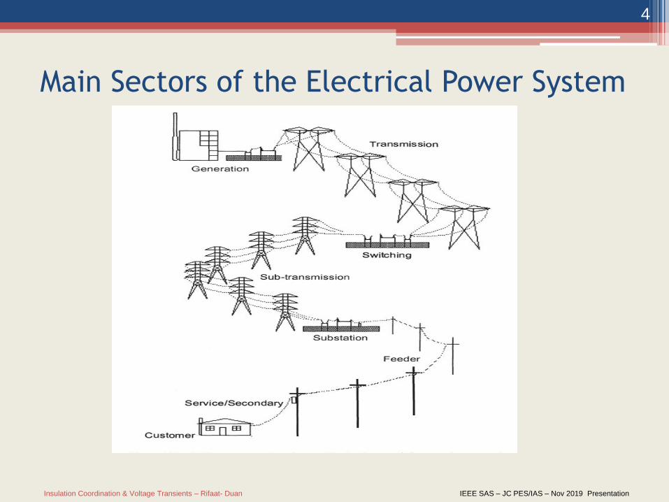
Main Sectors of the Electrical Power System
Insulation Coordination & Voltage Transients – Rifaat- Duan IEEE SAS – JC PES/IAS – Nov 2019 Presentation
5
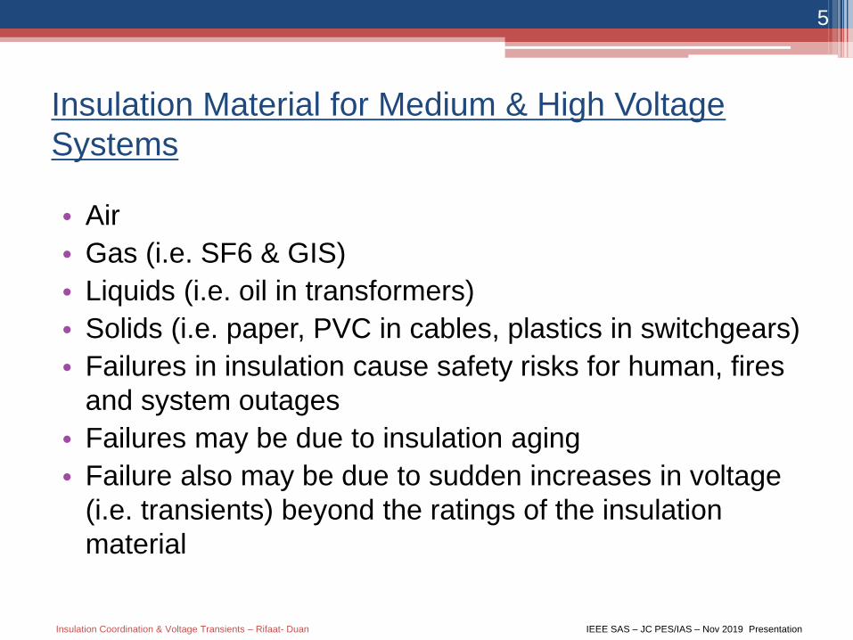
Insulation Material for Medium & High Voltage
Systems
• Air
• Gas (i.e. SF6 & GIS)
• Liquids (i.e. oil in transformers)
• Solids (i.e. paper, PVC in cables, plastics in switchgears)
• Failures in insulation cause safety risks for human, fires
and system outages
• Failures may be due to insulation aging
• Failure also may be due to sudden increases in voltage
(i.e. transients) beyond the ratings of the insulation
material

Insulation Coordination & Voltage Transients – Rifaat- Duan IEEE SAS – JC PES/IAS – Nov 2019 Presentation
6
Examples of Insulation in HV and MV Systems
Insulation Coordination & Voltage Transients – Rifaat- Duan IEEE SAS – JC PES/IAS – Nov 2019 Presentation
7
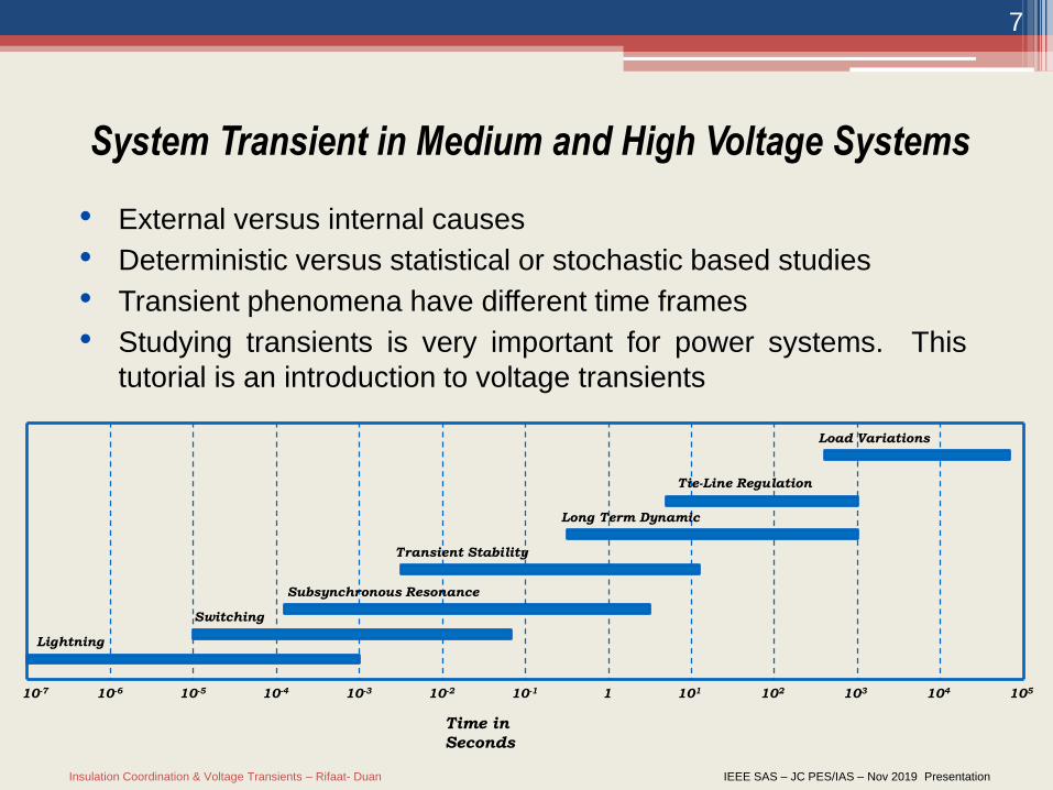
• External versus internal causes
• Deterministic versus statistical or stochastic based studies
• Transient phenomena have different time frames
• Studying transients is very important for power systems. This
tutorial is an introduction to voltage transients
System Transient in Medium and High Voltage Systems
10-7 10-6 10-5 10-4 10-3 10-2 10-1 1 101 102 103 104 105
Lightning
Switching
Subsynchronous Resonance
Transient Stability
Long Term Dynamic
Tie-Line Regulation
Load Variations
Time in
Seconds
Insulation Coordination & Voltage Transients – Rifaat- Duan IEEE SAS – JC PES/IAS – Nov 2019 Presentation
8
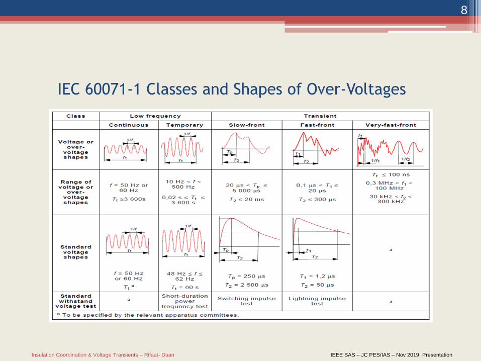
IEC 60071-1 Classes and Shapes of Over-Voltages
Insulation Coordination & Voltage Transients – Rifaat- Duan IEEE SAS – JC PES/IAS – Nov 2019 Presentation
9
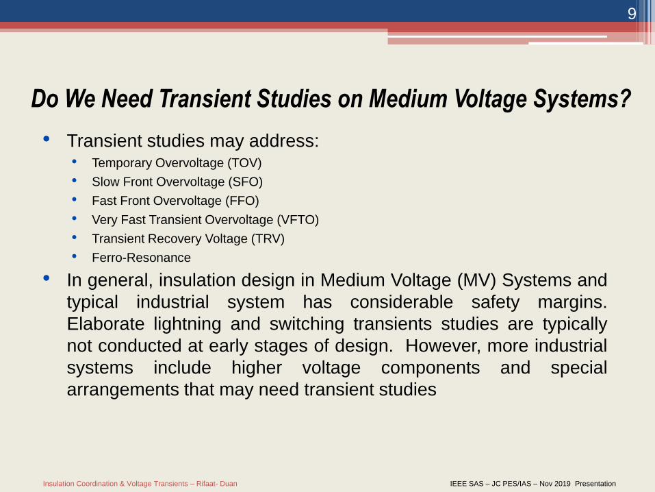
• Transient studies may address:• Temporary Overvoltage (TOV)
• Slow Front Overvoltage (SFO)
• Fast Front Overvoltage (FFO)
• Very Fast Transient Overvoltage (VFTO)
• Transient Recovery Voltage (TRV)
• Ferro-Resonance
• In general, insulation design in Medium Voltage (MV) Systems and
typical industrial system has considerable safety margins.
Elaborate lightning and switching transients studies are typically
not conducted at early stages of design. However, more industrial
systems include higher voltage components and special
arrangements that may need transient studies
Do We Need Transient Studies on Medium Voltage Systems?
Insulation Coordination & Voltage Transients – Rifaat- Duan IEEE SAS – JC PES/IAS – Nov 2019 Presentation
10
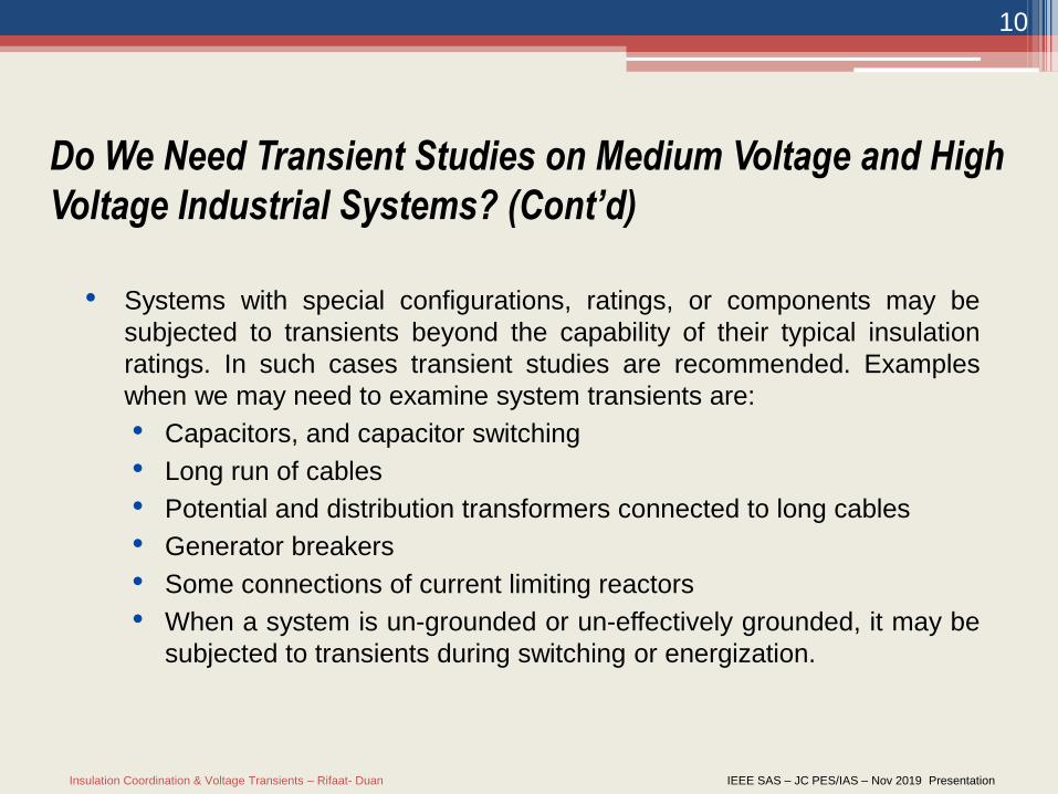
• Systems with special configurations, ratings, or components may be
subjected to transients beyond the capability of their typical insulation
ratings. In such cases transient studies are recommended. Examples
when we may need to examine system transients are:
• Capacitors, and capacitor switching
• Long run of cables
• Potential and distribution transformers connected to long cables
• Generator breakers
• Some connections of current limiting reactors
• When a system is un-grounded or un-effectively grounded, it may be
subjected to transients during switching or energization.
Do We Need Transient Studies on Medium Voltage and High
Voltage Industrial Systems? (Cont’d)
Insulation Coordination & Voltage Transients – Rifaat- Duan IEEE SAS – JC PES/IAS – Nov 2019 Presentation
11
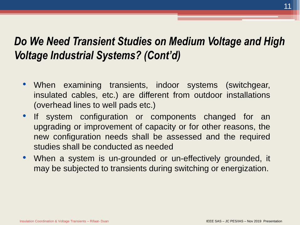
• When examining transients, indoor systems (switchgear,
insulated cables, etc.) are different from outdoor installations
(overhead lines to well pads etc.)
• If system configuration or components changed for an
upgrading or improvement of capacity or for other reasons, the
new configuration needs shall be assessed and the required
studies shall be conducted as needed
• When a system is un-grounded or un-effectively grounded, it
may be subjected to transients during switching or energization.
Do We Need Transient Studies on Medium Voltage and High
Voltage Industrial Systems? (Cont’d)
Insulation Coordination & Voltage Transients – Rifaat- Duan IEEE SAS – JC PES/IAS – Nov 2019 Presentation
12
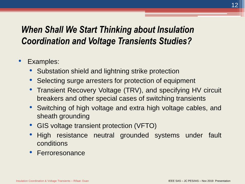
• Examples:
• Substation shield and lightning strike protection
• Selecting surge arresters for protection of equipment
• Transient Recovery Voltage (TRV), and specifying HV circuit
breakers and other special cases of switching transients
• Switching of high voltage and extra high voltage cables, and
sheath grounding
• GIS voltage transient protection (VFTO)
• High resistance neutral grounded systems under fault
conditions
• Ferroresonance
When Shall We Start Thinking about Insulation
Coordination and Voltage Transients Studies?
Insulation Coordination & Voltage Transients – Rifaat- Duan IEEE SAS – JC PES/IAS – Nov 2019 Presentation
13
• Standards Methods as demonstrated in Guides and
Recommended Practices (tools such as spreadsheets etc.)
• Transients software (mostly Time Domain)
• Example is Electro-Magnetic Transient Programs (EMTP)
such as ATP, PSCAD, EMTP-RV etc.
• Correct modeling of equipment is critical when using
software
What Tools Can Be Used for Typical Studies?
Insulation Coordination & Voltage Transients – Rifaat- Duan IEEE SAS – JC PES/IAS – Nov 2019 Presentation
14
Insulation Coordination
Insulation Coordination & Voltage Transients – Rifaat- Duan IEEE SAS – JC PES/IAS – Nov 2019 Presentation
15
Definition for “Insulation Coordination”
• Understanding the definition associated with “Insulation
Coordination” is very important for performing relevant studies
• Definitions are listed in several references, and in this presentation
we selected those listed in IEEE Std 62.82.1 as our referenced
definitions
• For demonstration purposes, we selected definitions associated
with our presentation topics. Other definitions are of an equal
importance and must be consulted when performing studies.
Insulation Coordination & Voltage Transients – Rifaat- Duan IEEE SAS – JC PES/IAS – Nov 2019 Presentation
16
Definition of “Insulation Coordination” as per IEEE Std 62.82.1
“insulation coordination”: The selection of the insulation strength of equipment in relation to the voltages, which can appear on the system for which equipment is intended and taking into account the service environment and the characteristics of the available protective devices.NOTE—An acceptable risk of failure is considered when selecting the insulation strength of equipment (Why & How much??)
Insulation Coordination & Voltage Transients – Rifaat- Duan IEEE SAS – JC PES/IAS – Nov 2019 Presentation
17
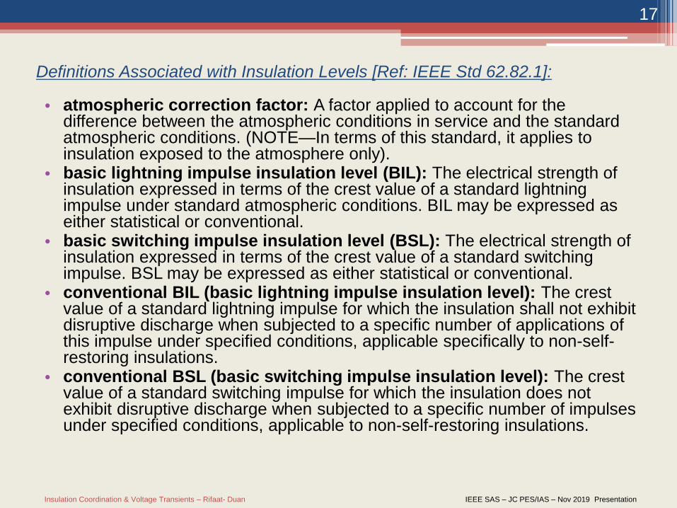
Definitions Associated with Insulation Levels [Ref: IEEE Std 62.82.1]:
• atmospheric correction factor: A factor applied to account for the difference between the atmospheric conditions in service and the standard atmospheric conditions. (NOTE—In terms of this standard, it applies to insulation exposed to the atmosphere only).
• basic lightning impulse insulation level (BIL): The electrical strength of insulation expressed in terms of the crest value of a standard lightning impulse under standard atmospheric conditions. BIL may be expressed as either statistical or conventional.
• basic switching impulse insulation level (BSL): The electrical strength of insulation expressed in terms of the crest value of a standard switching impulse. BSL may be expressed as either statistical or conventional.
• conventional BIL (basic lightning impulse insulation level): The crest value of a standard lightning impulse for which the insulation shall not exhibit disruptive discharge when subjected to a specific number of applications of this impulse under specified conditions, applicable specifically to non-self-restoring insulations.
• conventional BSL (basic switching impulse insulation level): The crest value of a standard switching impulse for which the insulation does not exhibit disruptive discharge when subjected to a specific number of impulses under specified conditions, applicable to non-self-restoring insulations.
Insulation Coordination & Voltage Transients – Rifaat- Duan IEEE SAS – JC PES/IAS – Nov 2019 Presentation
18
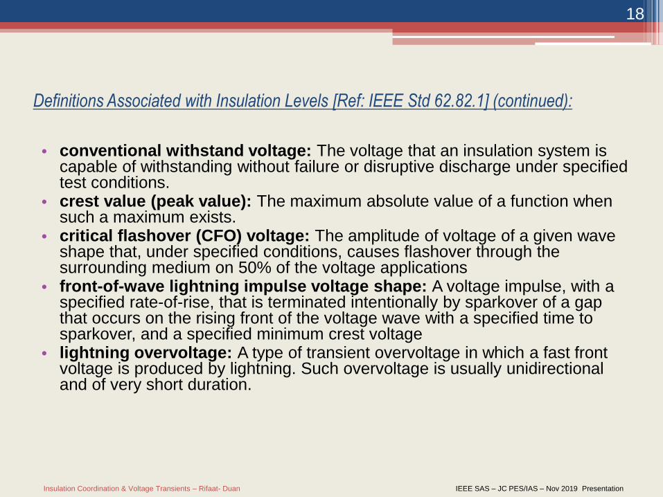
Definitions Associated with Insulation Levels [Ref: IEEE Std 62.82.1] (continued):
• conventional withstand voltage: The voltage that an insulation system is capable of withstanding without failure or disruptive discharge under specified test conditions.
• crest value (peak value): The maximum absolute value of a function when such a maximum exists.
• critical flashover (CFO) voltage: The amplitude of voltage of a given wave shape that, under specified conditions, causes flashover through the surrounding medium on 50% of the voltage applications
• front-of-wave lightning impulse voltage shape: A voltage impulse, with a specified rate-of-rise, that is terminated intentionally by sparkover of a gap that occurs on the rising front of the voltage wave with a specified time to sparkover, and a specified minimum crest voltage
• lightning overvoltage: A type of transient overvoltage in which a fast front voltage is produced by lightning. Such overvoltage is usually unidirectional and of very short duration.
Insulation Coordination & Voltage Transients – Rifaat- Duan IEEE SAS – JC PES/IAS – Nov 2019 Presentation
19
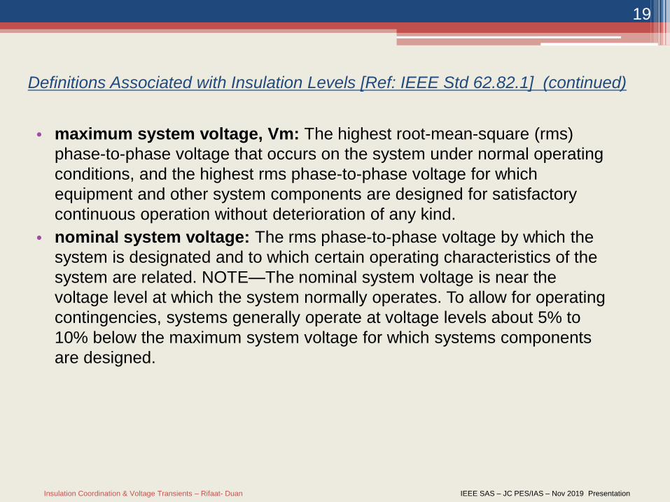
Definitions Associated with Insulation Levels [Ref: IEEE Std 62.82.1] (continued)
• maximum system voltage, Vm: The highest root-mean-square (rms)
phase-to-phase voltage that occurs on the system under normal operating
conditions, and the highest rms phase-to-phase voltage for which
equipment and other system components are designed for satisfactory
continuous operation without deterioration of any kind.
• nominal system voltage: The rms phase-to-phase voltage by which the
system is designated and to which certain operating characteristics of the
system are related. NOTE—The nominal system voltage is near the
voltage level at which the system normally operates. To allow for operating
contingencies, systems generally operate at voltage levels about 5% to
10% below the maximum system voltage for which systems components
are designed.
Insulation Coordination & Voltage Transients – Rifaat- Duan IEEE SAS – JC PES/IAS – Nov 2019 Presentation
20
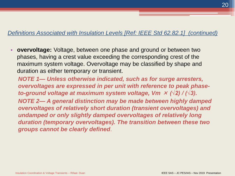
Definitions Associated with Insulation Levels [Ref: IEEE Std 62.82.1] (continued)
• overvoltage: Voltage, between one phase and ground or between two
phases, having a crest value exceeding the corresponding crest of the
maximum system voltage. Overvoltage may be classified by shape and
duration as either temporary or transient.
NOTE 1— Unless otherwise indicated, such as for surge arresters,
overvoltages are expressed in per unit with reference to peak phase-
to-ground voltage at maximum system voltage, Vm × (√2) / (√3).
NOTE 2— A general distinction may be made between highly damped
overvoltages of relatively short duration (transient overvoltages) and
undamped or only slightly damped overvoltages of relatively long
duration (temporary overvoltages). The transition between these two
groups cannot be clearly defined.
Insulation Coordination & Voltage Transients – Rifaat- Duan IEEE SAS – JC PES/IAS – Nov 2019 Presentation
21
Definitions Associated with Insulation Levels [Ref: IEEE Std 62.82.1] (continued)
• performance criterion: The criterion upon which the insulation strength or
withstand voltages and clearances are selected. The performance criterion
is based on an acceptable probability of insulation failure and is determined
by the consequence of failure, required level of reliability, expected life of
equipment, economics, and operational requirements. The criterion is
usually expressed in terms of an acceptable failure rate (number of failures
per year, years between failures, risk of failure, etc.) of the insulation
configuration.
Insulation Coordination & Voltage Transients – Rifaat- Duan IEEE SAS – JC PES/IAS – Nov 2019 Presentation
22
Definitions Associated with Insulation Levels [Ref: IEEE Std 62.82.1] (continued)
• protective margin (PM): The value of the protective ratio (PR), minus
one, expressed as a percentage. PM = (PR − 1) × 100.
• protective ratio (PR): The ratio of the insulation strength of the protected
equipment to the overvoltages appearing across the insulation.
• lightning impulse protective level of a surge-protective device: The
maximum lightning impulse voltage expected at the terminals of a surge-
protective device under specified conditions of operation.
• NOTE—The lightning impulse protective levels are simulated by the
following: 1) front-of-wave impulse sparkover or discharge voltage and 2)
the higher of either a 1.2/50 impulse sparkover voltage or the discharge
voltage for a specified current magnitude and wave shape.
Insulation Coordination & Voltage Transients – Rifaat- Duan IEEE SAS – JC PES/IAS – Nov 2019 Presentation
23
Definitions Associated with Insulation Material & Configuration [Ref: IEEE Std 62.82.1]
• external insulation: The air insulation and the exposed surfaces of solid insulation of equipment, which are both subject to dielectric stresses and to the effects of atmospheric and other external conditions such as contamination, humidity, and vermin.
• internal insulation: Internal insulation comprises the internal solid, liquid, or gaseous elements of the insulation of equipment, which are protected from the effects of atmospheric and other external conditions such as contamination, humidity, and vermin.
• non-self-restoring insulation: An insulation that loses its insulating properties or does not recover them completely, after a disruptive discharge caused by the application of a test voltage; insulation of this kind is generally, but not necessarily, internal insulation.
• self-restoring insulation: Insulation that completely recovers its insulating properties after a disruptive discharge caused by the application of a test voltage; insulation of this kind is generally, but not necessarily, external insulation.
• insulation configuration: The complete geometric configuration of the insulation, including all elements (insulating and conducting) that influence its dielectric behavior. Examples of insulation configurations are phase-to-ground, phase-to-phase, and longitudinal.
Insulation Coordination & Voltage Transients – Rifaat- Duan IEEE SAS – JC PES/IAS – Nov 2019 Presentation
24
Overvoltage Transients Protection &
Applications of Surge Arresters
Insulation Coordination & Voltage Transients – Rifaat- Duan IEEE SAS – JC PES/IAS – Nov 2019 Presentation
25
Introduction
What is a surge arrestor?
A protective device for limiting surge voltages on equipment by discharging or
bypassing surge current; it limits the flow of power current to ground and is
capable of repeating these functions as specified (Ref: IEEE Std. C62.22-
2009).
Why do we need surge arrestors?
To provide protection to equipment insulation from abnormal overvoltage.
NOTE – surge arrestor can only be activated by non-power frequency overvoltage (lightning or switching surge)
Insulation Coordination & Voltage Transients – Rifaat- Duan IEEE SAS – JC PES/IAS – Nov 2019 Presentation
26
Definitions
Arrester Discharge Current:
The current that flows through an arrester resulting from an impinging surge
(Ref: IEEE Std. C62.22-2009).
Arrester Discharge Voltage or Residual Voltage:
The voltage that appears across the terminals of an arrester during the
passage of discharge current (Ref: IEEE Std. C62.22-2009).
Insulation Coordination & Voltage Transients – Rifaat- Duan IEEE SAS – JC PES/IAS – Nov 2019 Presentation
27
General Considerations for Arrester’s
Applications
1. Arrester Class
2. Arrester MCOV
3. Temporary Over voltage (TOV) Capacity
4. Protection Ratio
5. Switching Impulse Energy Handling Capability
6. Arrester Pressure Relief Capability
Insulation Coordination & Voltage Transients – Rifaat- Duan IEEE SAS – JC PES/IAS – Nov 2019 Presentation
28
Arrester Class:
The arrester class is designed base on the:
1. Required level of protection
2. Available voltage ratings
3. Pressure relief current limits (short circuit
withstand)
4. Durability
Insulation Coordination & Voltage Transients – Rifaat- Duan IEEE SAS – JC PES/IAS – Nov 2019 Presentation
29
Arrester Class (Cont’d)
• Station class arresters for heavy duty
application, and most durable
• Intermediate class arresters for moderate-
duty application (maximum system voltage
169kV)
• Distribution class arresters for lower
voltage transformers, transmission and
distribution lines
Insulation Coordination & Voltage Transients – Rifaat- Duan IEEE SAS – JC PES/IAS – Nov 2019 Presentation
30
Class Applications
• Station class arresters for heavy duty application, and
most durable
• Intermediate class arresters for moderate-duty
application (maximum system voltage 169kV)
• Distribution class arresters for lower voltage
transformers, transmission and distribution lines
Insulation Coordination & Voltage Transients – Rifaat- Duan IEEE SAS – JC PES/IAS – Nov 2019 Presentation
31
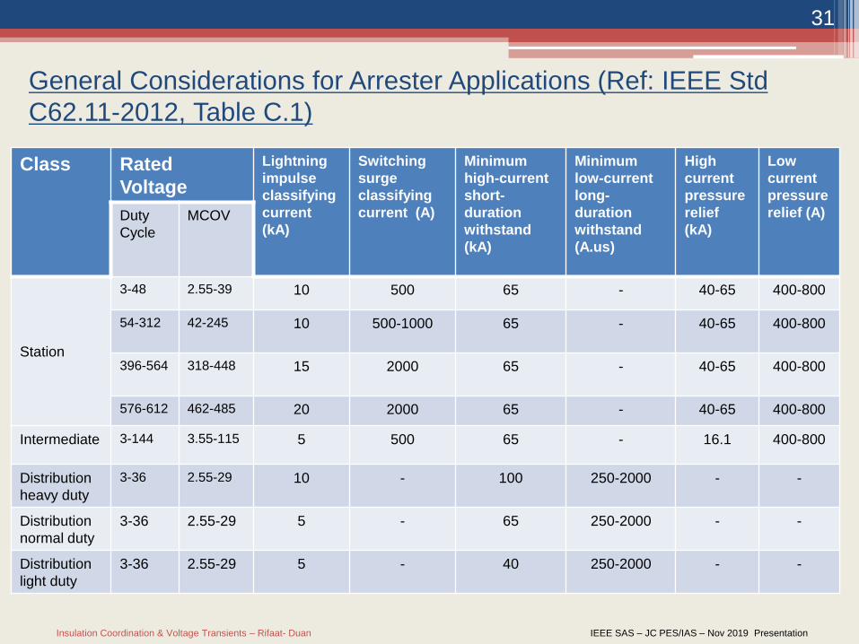
General Considerations for Arrester Applications (Ref: IEEE Std
C62.11-2012, Table C.1)
Class Rated
Voltage
Lightning
impulse
classifying
current
(kA)
Switching
surge
classifying
current (A)
Minimum
high-current
short-
duration
withstand
(kA)
Minimum
low-current
long-
duration
withstand
(A.us)
High
current
pressure
relief
(kA)
Low
current
pressure
relief (A)Duty
Cycle
MCOV
Station
3-48 2.55-39 10 500 65 - 40-65 400-800
54-312 42-245 10 500-1000 65 - 40-65 400-800
396-564 318-448 15 2000 65 - 40-65 400-800
576-612 462-485 20 2000 65 - 40-65 400-800
Intermediate 3-144 3.55-115 5 500 65 - 16.1 400-800
Distribution
heavy duty
3-36 2.55-29 10 - 100 250-2000 - -
Distribution
normal duty
3-36 2.55-29 5 - 65 250-2000 - -
Distribution
light duty
3-36 2.55-29 5 - 40 250-2000 - -
Insulation Coordination & Voltage Transients – Rifaat- Duan IEEE SAS – JC PES/IAS – Nov 2019 Presentation
32
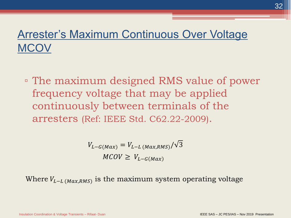
Arrester’s Maximum Continuous Over Voltage
MCOV
▫ The maximum designed RMS value of power
frequency voltage that may be applied
continuously between terminals of the
arresters (Ref: IEEE Std. C62.22-2009).
𝑉𝐿−𝐺(𝑀𝑎𝑥) = 𝑉𝐿−𝐿 (𝑀𝑎𝑥,𝑅𝑀𝑆)/ 3
𝑀𝐶𝑂𝑉 ≥ 𝑉𝐿−𝐺 𝑀𝑎𝑥
Where 𝑉𝐿−𝐿 (𝑀𝑎𝑥,𝑅𝑀𝑆) is the maximum system operating voltage
Insulation Coordination & Voltage Transients – Rifaat- Duan IEEE SAS – JC PES/IAS – Nov 2019 Presentation
33
Arrester’s Maximum Temporary Over Voltage
(TOV)
Temporary Over Voltage (TOV) Capability:
• Consist of lightly damped power frequency voltage
oscillation, often with harmonics, usually lasting a
period of hundreds of milliseconds or longer.
• Arrester is capable of operating for limited periods
of time at voltage in excess of MCOV rating.
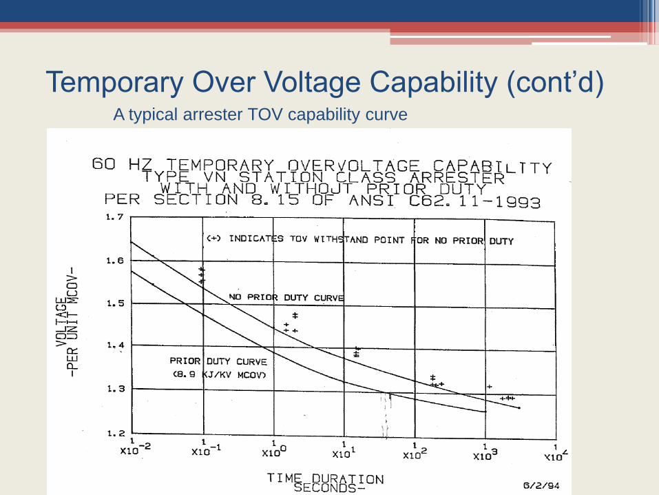
Temporary Over Voltage Capability (cont’d)A typical arrester TOV capability curve
Insulation Coordination & Voltage Transients – Rifaat- Duan IEEE SAS – JC PES/IAS – Nov 2019 Presentation
35
Temporary Over Voltage (TOV) Capability
• While selecting the arrester’s MCOV,
considerations need to be given to the
arresters “TOV” capability
• The basic requirement is that the power
frequency voltage versus time needs to be
higher than the TOV amplitude versus
duration characteristics.
Insulation Coordination & Voltage Transients – Rifaat- Duan IEEE SAS – JC PES/IAS – Nov 2019 Presentation
36
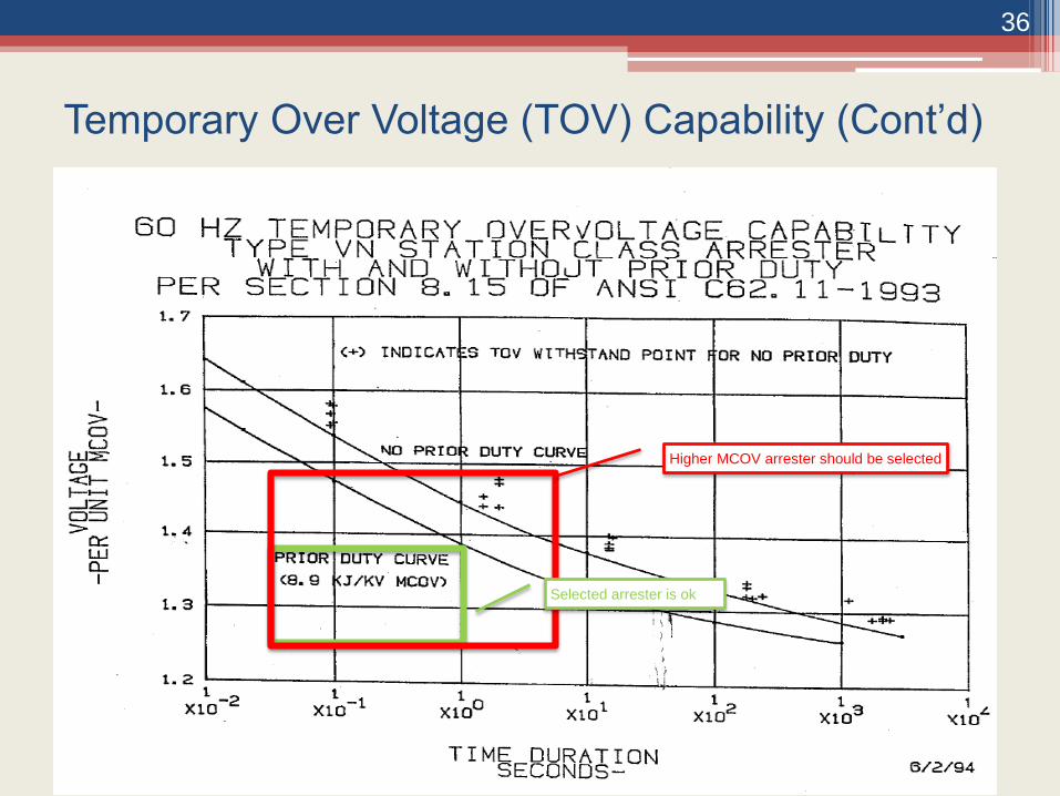
Temporary Over Voltage (TOV) Capability (Cont’d)
Higher MCOV arrester should be selected
Selected arrester is ok
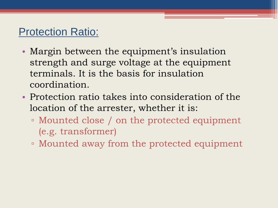
Protection Ratio:
• Margin between the equipment’s insulation
strength and surge voltage at the equipment
terminals. It is the basis for insulation
coordination.
• Protection ratio takes into consideration of the
location of the arrester, whether it is:
▫ Mounted close / on the protected equipment
(e.g. transformer)
▫ Mounted away from the protected equipment
Insulation Coordination & Voltage Transients – Rifaat- Duan IEEE SAS – JC PES/IAS – Nov 2019 Presentation
38
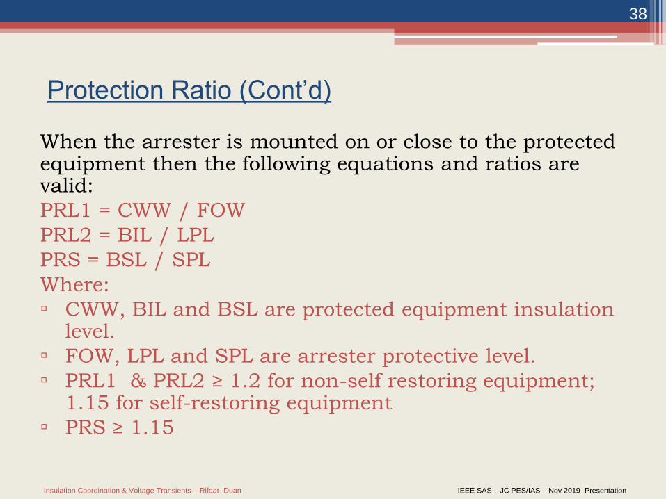
Protection Ratio (Cont’d)
When the arrester is mounted on or close to the protected equipment then the following equations and ratios are valid:
PRL1 = CWW / FOW
PRL2 = BIL / LPL
PRS = BSL / SPL
Where:
▫ CWW, BIL and BSL are protected equipment insulation level.
▫ FOW, LPL and SPL are arrester protective level.
▫ PRL1 & PRL2 ≥ 1.2 for non-self restoring equipment; 1.15 for self-restoring equipment
▫ PRS ≥ 1.15
Insulation Coordination & Voltage Transients – Rifaat- Duan IEEE SAS – JC PES/IAS – Nov 2019 Presentation
39
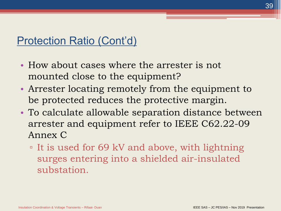
Protection Ratio (Cont’d)
• How about cases where the arrester is not
mounted close to the equipment?
• Arrester locating remotely from the equipment to
be protected reduces the protective margin.
• To calculate allowable separation distance between
arrester and equipment refer to IEEE C62.22-09
Annex C
▫ It is used for 69 kV and above, with lightning
surges entering into a shielded air-insulated
substation.
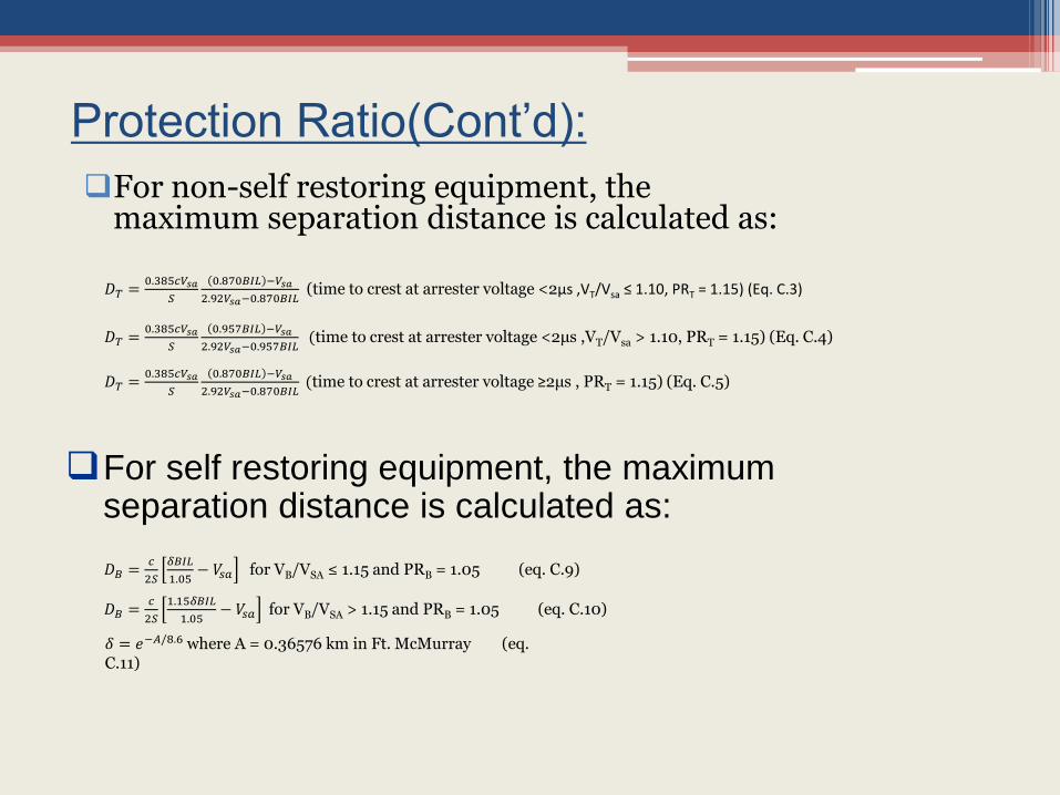
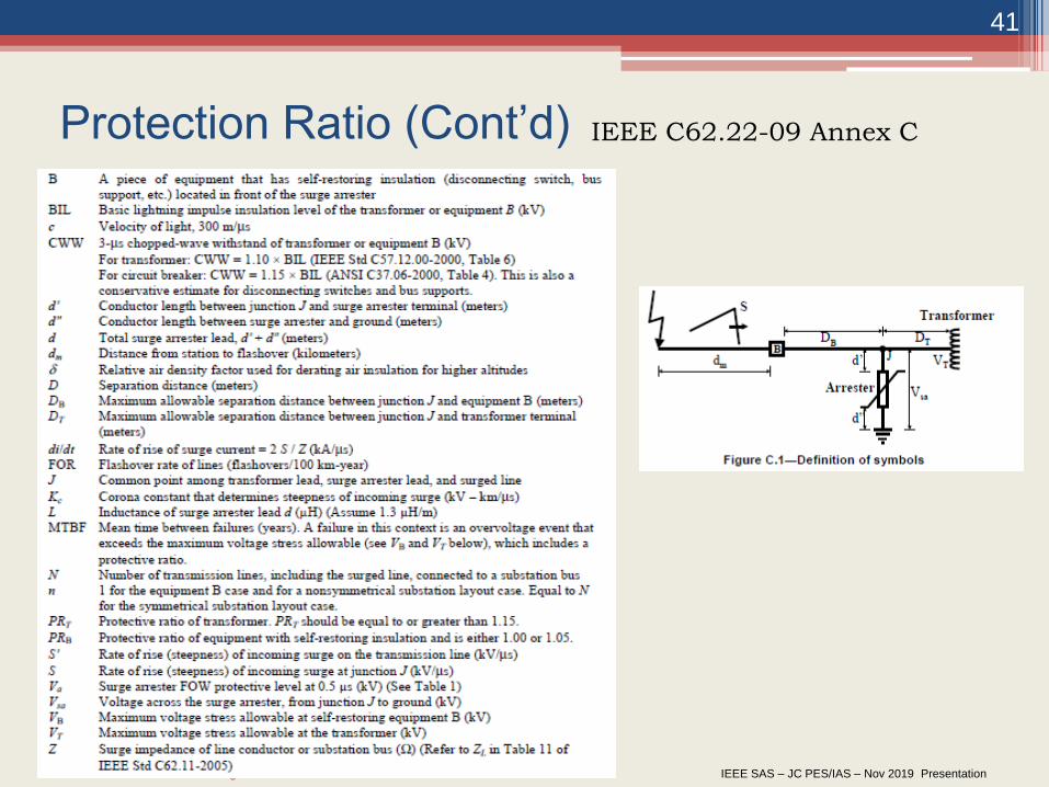
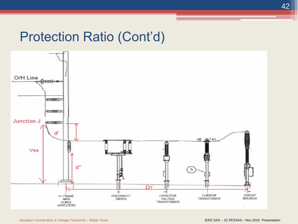
Protection Ratio(Cont’d):
For non-self restoring equipment, the maximum separation distance is calculated as:
𝐷𝑇 =0.385𝑐𝑉𝑠𝑎
𝑆
0.870𝐵𝐼𝐿 −𝑉𝑠𝑎
2.92𝑉𝑠𝑎−0.870𝐵𝐼𝐿(time to crest at arrester voltage <2μs ,VT/Vsa ≤ 1.10, PRT = 1.15) (Eq. C.3)
𝐷𝑇 =0.385𝑐𝑉𝑠𝑎
𝑆
0.957𝐵𝐼𝐿 −𝑉𝑠𝑎
2.92𝑉𝑠𝑎−0.957𝐵𝐼𝐿(time to crest at arrester voltage <2μs ,VT/Vsa > 1.10, PRT = 1.15) (Eq. C.4)
𝐷𝑇 =0.385𝑐𝑉𝑠𝑎
𝑆
0.870𝐵𝐼𝐿 −𝑉𝑠𝑎
2.92𝑉𝑠𝑎−0.870𝐵𝐼𝐿(time to crest at arrester voltage ≥2μs , PRT = 1.15) (Eq. C.5)
For self restoring equipment, the maximum separation distance is calculated as:
𝐷𝐵 =𝑐
2𝑆
𝛿𝐵𝐼𝐿
1.05− 𝑉𝑠𝑎 for VB/VSA ≤ 1.15 and PRB = 1.05 (eq. C.9)
𝐷𝐵 =𝑐
2𝑆
1.15𝛿𝐵𝐼𝐿
1.05− 𝑉𝑠𝑎 for VB/VSA > 1.15 and PRB = 1.05 (eq. C.10)
𝛿 = 𝑒−𝐴/8.6 where A = 0.36576 km in Ft. McMurray (eq. C.11)
Insulation Coordination & Voltage Transients – Rifaat- Duan IEEE SAS – JC PES/IAS – Nov 2019 Presentation
41
Protection Ratio (Cont’d) IEEE C62.22-09 Annex C
Insulation Coordination & Voltage Transients – Rifaat- Duan IEEE SAS – JC PES/IAS – Nov 2019 Presentation
42
Protection Ratio (Cont’d)
Insulation Coordination & Voltage Transients – Rifaat- Duan IEEE SAS – JC PES/IAS – Nov 2019 Presentation
43
Switching Impulse Energy Handling
Capabilities
When the arrester is energized, it will absorb energy resulting in an increase in temperature. Under normal operating conditions, there is a balance between the heat generated in an arrester and the heat dissipated by the arrester. With such balance, a stable condition is maintained.
During over voltage conditions (switching surge) the arrester absorbs more energy. If the temperature of the arrester is too high, the arrester can be driven into a state of thermal run away.
Insulation Coordination & Voltage Transients – Rifaat- Duan IEEE SAS – JC PES/IAS – Nov 2019 Presentation
44
Switching Impulse Energy Handling
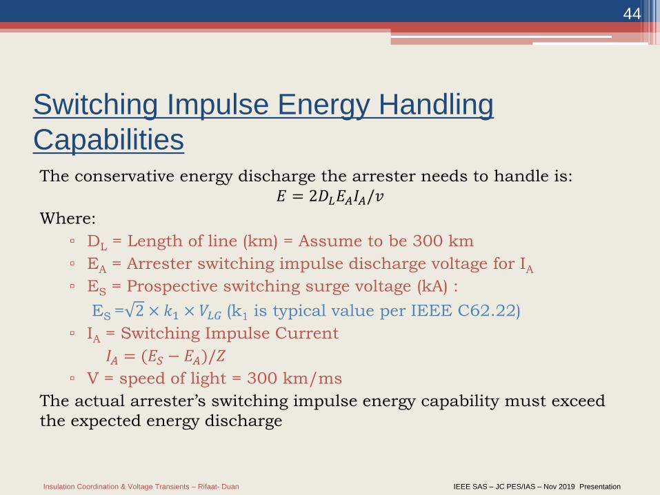
Capabilities The conservative energy discharge the arrester needs to handle is:
𝐸 = 2𝐷𝐿𝐸𝐴𝐼𝐴/𝑣
Where:
▫ DL = Length of line (km) = Assume to be 300 km
▫ EA = Arrester switching impulse discharge voltage for IA
▫ ES = Prospective switching surge voltage (kA) :
ES = 2 × 𝑘1 × 𝑉𝐿𝐺 (k1 is typical value per IEEE C62.22)
▫ IA = Switching Impulse Current
𝐼𝐴 = (𝐸𝑆 − 𝐸𝐴)/𝑍
▫ V = speed of light = 300 km/ms
The actual arrester’s switching impulse energy capability must exceed
the expected energy discharge
Insulation Coordination & Voltage Transients – Rifaat- Duan IEEE SAS – JC PES/IAS – Nov 2019 Presentation
45
Arrester’s Pressure Relief Capability
It is the short circuit rating of the arrester which should not be exceeded
by the system’s available short circuit current at the arrester location
Insulation Coordination & Voltage Transients – Rifaat- Duan IEEE SAS – JC PES/IAS – Nov 2019 Presentation
46
Modeling Breakers for Studying
Transient Recovery Voltage (TRV)
Insulation Coordination & Voltage Transients – Rifaat- Duan IEEE SAS – JC PES/IAS – Nov 2019 Presentation
47
Transient Recovery Voltage (TRV)- An Introduction
By definition TRV is the voltage appearing across the terminals of a circuit
breaker after a switching event has occurred when interrupting:
Fault Current,
Inductive Current,
Capacitive Current.
It represents the difference in the power system response voltage from line
side to load side of the circuit breaker.
Insulation Coordination & Voltage Transients – Rifaat- Duan IEEE SAS – JC PES/IAS – Nov 2019 Presentation
48
Transient Recovery Voltage (TRV)- An Introduction
The concern:
When current flow stops (after the initial few μsec) the power
system response is a transient expressed as TRV.
With multiphase faults sequential interruption of fault current
leads to power system recovery voltages higher than rated,
which leads to circuit breaker restrike and non-interruption
of current flow.
Insulation Coordination & Voltage Transients – Rifaat- Duan IEEE SAS – JC PES/IAS – Nov 2019 Presentation
49
Transient Recovery Voltage (TRV)
Behavior Example
In some cases the system response has an oscillatory and power frequency
component. An example is a three phase to ground terminal fault at the
circuit breaker. For this case the:
Initial time interval consists of a transient voltage with an axis of
oscillation around the recovery voltage.
Second interval represents the power frequency recovery voltage.
▫ (do we have a plot from existing study that can be inserted here)
Insulation Coordination & Voltage Transients – Rifaat- Duan IEEE SAS – JC PES/IAS – Nov 2019 Presentation
50
Transient Recovery Voltage (TRV)
Transient Analysis
All transients have:
An initial condition which may be zero or a finite value,
An axis of oscillation that becomes the actual steady state value when the transient has died out,
A maximum value depending on the degree of damping,
A certain frequency determined by the values of L and C.
Oscillatory components of TRV can be analyzed using RLC circuits and applying
differential equations.
Three of the RLC cases have a common 2nd order homogeneous differential solution of
the form:
y = Aer1x + Ber2x; where roots r1 and r2 are derived from the circuit RLC components
and A and B from the initial boundary conditions.
The fourth case uses a 2nd order non-homogeneous differential solution using lookup
tables and the method of undetermined coefficients to solve the equation.
Insulation Coordination & Voltage Transients – Rifaat- Duan IEEE SAS – JC PES/IAS – Nov 2019 Presentation
51
Transient Recovery Voltage (TRV) – Pole Factors
For a circuit breaker opening under a fault there is sequential interruption of fault
current. The first circuit breaker pole clears and the system becomes unbalanced
causing the recovery voltage to exceed its normal phase to ground value.
Under fault conditions two cases that affect recovery voltage levels can be
considered:
An Effectively Grounded system where the ratio of symmetrical reactance X0
to X1 is 3 or less,
A Non-Effectively Grounded system where the neutral is isolated, high
impedance or resonant grounded.
For the cases listed above the TRV is based on a power frequency component
determined by the first pole to clear factor (kpp) and an oscillatory (or aperiodic)
component based on the amplitude factor (kaf).
Circuit breakers can interrupt rated fault levels at or near unity power factor with little
or no problem, however at a zero power factor leading or lagging the TRV can impose
a great challenge.
Insulation Coordination & Voltage Transients – Rifaat- Duan IEEE SAS – JC PES/IAS – Nov 2019 Presentation
52
Transient Recovery Voltage (TRV)
Pole Factors (cont’d)
For an Effectively Grounded circuit the first and second pole to clear factor is
derived from sequence components and calculated as:
k pp1 = 3 (X0/X1) / (1 + 2 (X0/X1))
k pp2 = (30.5 / (2+(X0/X1)) / ((1 + (X0/X1) + (X0/X1)2 )0.5
k pp3 = 1 as the system is now balanced,
Amplitude Factor (kaf) is the ratio of the peak voltage value to the axis of
oscillation with both being relative to the starting point.
k af = 1 + β where β = (B – A) / A (see graph below).
▫ (reproduce graph from Peelo, page 25, Fig 2.9)
Insulation Coordination & Voltage Transients – Rifaat- Duan IEEE SAS – JC PES/IAS – Nov 2019 Presentation
53
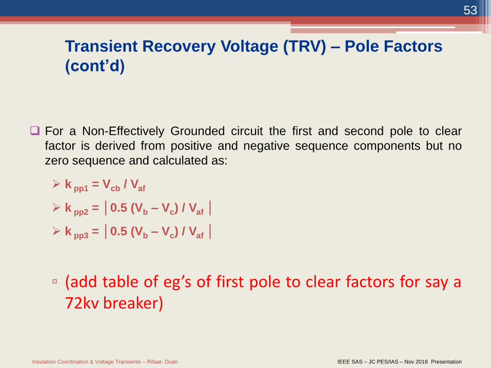
Transient Recovery Voltage (TRV) – Pole Factors
(cont’d)
For a Non-Effectively Grounded circuit the first and second pole to clear
factor is derived from positive and negative sequence components but no
zero sequence and calculated as:
k pp1 = Vcb / Vaf
k pp2 = │0.5 (Vb – Vc) / Vaf │
k pp3 = │0.5 (Vb – Vc) / Vaf │
▫ (add table of eg’s of first pole to clear factors for say a72kv breaker)
Insulation Coordination & Voltage Transients – Rifaat- Duan IEEE SAS – JC PES/IAS – Nov 2019 Presentation
54
Modelling Vacuum Breakers for
Transient Analysis:
• Modelling is done to imitate real life. It has to be accurate
especially for the intended purpose. How can we model
an arc in a circuit breaker?
Insulation Coordination & Voltage Transients – Rifaat- Duan IEEE SAS – JC PES/IAS – Nov 2019 Presentation
55
• Three basic models with variants:• Physical arc models
• Black box models
• Formulas and calculations
• Models applications were described in CIGRE, Work
Group 13.01 “Practical applications of arc physics in circuit
breakers. Survey of calculation methods and application
guide; Electra No.: 118, pages: 64-79, 1988
• CIGRE’s report shows the preferred modelling methods
for:• Development
• Testing
• Operation
Modelling Vacuum Breakers for
Transient Analysis:
Insulation Coordination & Voltage Transients – Rifaat- Duan IEEE SAS – JC PES/IAS – Nov 2019 Presentation
56
• For development and testing all three arc model types are
used
• For Operation Black Box Type Models (BB) are used:• Influence of arc asymmetry and delayed current zero
• Small inductive currents
• Short line faults including TRV
• Formulas and calculations models are used for:• Description of dielectric recovery
• Small inductive currents (alongside with BB)
• Short line faults including TRV (Alongside with BB)
Modelling Guidelines for Arcs in
Breakers
Insulation Coordination & Voltage Transients – Rifaat- Duan IEEE SAS – JC PES/IAS – Nov 2019 Presentation
57
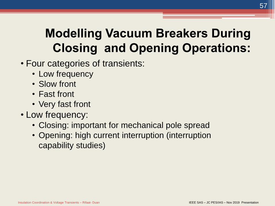
• Four categories of transients:• Low frequency
• Slow front
• Fast front
• Very fast front
• Low frequency:• Closing: important for mechanical pole spread
• Opening: high current interruption (interruption
capability studies)
Modelling Vacuum Breakers During
Closing and Opening Operations:
Insulation Coordination & Voltage Transients – Rifaat- Duan IEEE SAS – JC PES/IAS – Nov 2019 Presentation
58
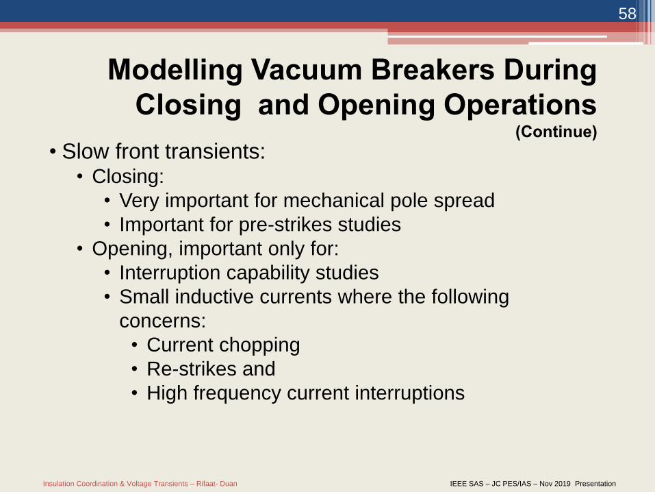
• Slow front transients:• Closing:
• Very important for mechanical pole spread
• Important for pre-strikes studies
• Opening, important only for:
• Interruption capability studies
• Small inductive currents where the following
concerns:
• Current chopping
• Re-strikes and
• High frequency current interruptions
Modelling Vacuum Breakers During
Closing and Opening Operations (Continue)
Insulation Coordination & Voltage Transients – Rifaat- Duan IEEE SAS – JC PES/IAS – Nov 2019 Presentation
59
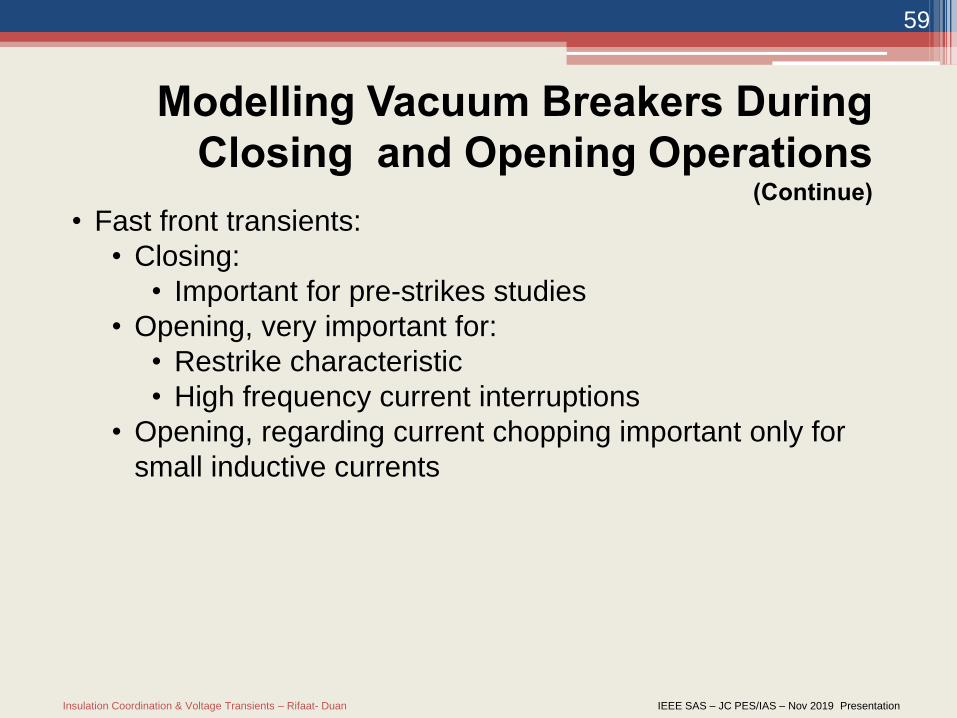
• Fast front transients:
• Closing:
• Important for pre-strikes studies
• Opening, very important for:
• Restrike characteristic
• High frequency current interruptions
• Opening, regarding current chopping important only for
small inductive currents
Modelling Vacuum Breakers During
Closing and Opening Operations (Continue)
Insulation Coordination & Voltage Transients – Rifaat- Duan IEEE SAS – JC PES/IAS – Nov 2019 Presentation
60
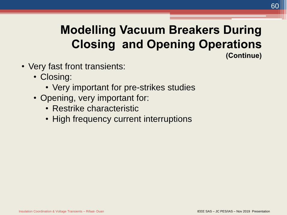
• Very fast front transients:
• Closing:
• Very important for pre-strikes studies
• Opening, very important for:
• Restrike characteristic
• High frequency current interruptions
Modelling Vacuum Breakers During
Closing and Opening Operations (Continue)
Insulation Coordination & Voltage Transients – Rifaat- Duan IEEE SAS – JC PES/IAS – Nov 2019 Presentation
61
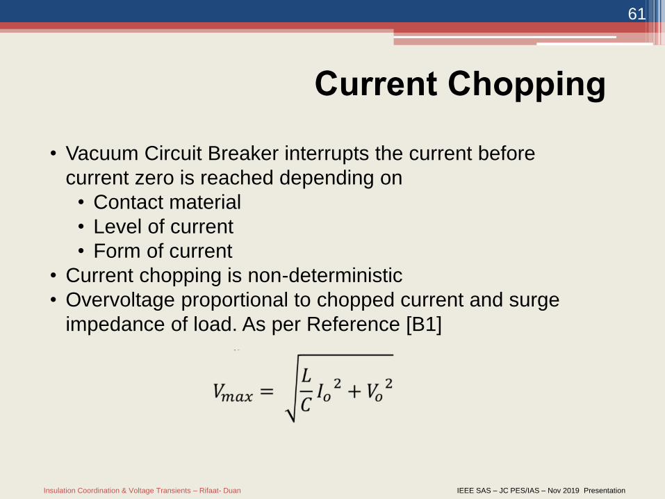
• Vacuum Circuit Breaker interrupts the current before
current zero is reached depending on
• Contact material
• Level of current
• Form of current
• Current chopping is non-deterministic
• Overvoltage proportional to chopped current and surge
impedance of load. As per Reference [B1]
Current Chopping
Insulation Coordination & Voltage Transients – Rifaat- Duan IEEE SAS – JC PES/IAS – Nov 2019 Presentation
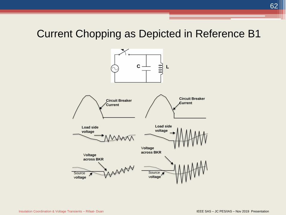
62
Current Chopping as Depicted in Reference B1
Circuit Breaker
Current
Circuit Breaker
Current
Load side
voltage
Load side
voltage
Voltage
across BKRVoltage
across BKR
Source
voltageSource
voltage
C L
Insulation Coordination & Voltage Transients – Rifaat- Duan IEEE SAS – JC PES/IAS – Nov 2019 Presentation
63
Current Chopping
Insulation Coordination & Voltage Transients – Rifaat- Duan IEEE SAS – JC PES/IAS – Nov 2019 Presentation
64
• Re-ignition in the VCB will appear in the form of a high
frequency current superimposed on the power frequency
current.
• Vacuum circuit breakers can quench high frequency
currents in the range of several hundred A/μs when they
cross current zero.
High Frequency Current Quenching
Insulation Coordination & Voltage Transients – Rifaat- Duan IEEE SAS – JC PES/IAS – Nov 2019 Presentation
65
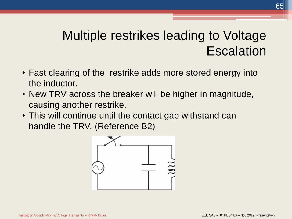
• Fast clearing of the restrike adds more stored energy into
the inductor.
• New TRV across the breaker will be higher in magnitude,
causing another restrike.
• This will continue until the contact gap withstand can
handle the TRV. (Reference B2)
Multiple restrikes leading to Voltage
Escalation
Insulation Coordination & Voltage Transients – Rifaat- Duan IEEE SAS – JC PES/IAS – Nov 2019 Presentation
66
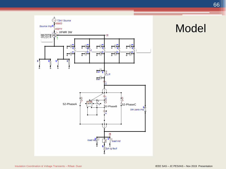
Model
52-PhaseA52-PhaseB
52-PhaseC
XFMR 3W
Insulation Coordination & Voltage Transients – Rifaat- Duan IEEE SAS – JC PES/IAS – Nov 2019 Presentation
67
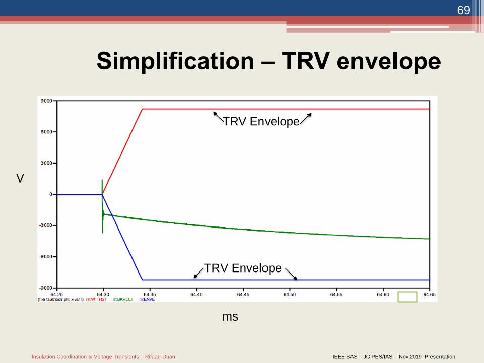
• Current Chopping assumed to be 5A
• Opening of breaker occurs during short circuit of load
• Contact gap withstand is given by the TRV Envelope from
IEEE C.37
Model Parameters
Insulation Coordination & Voltage Transients – Rifaat- Duan IEEE SAS – JC PES/IAS – Nov 2019 Presentation
68
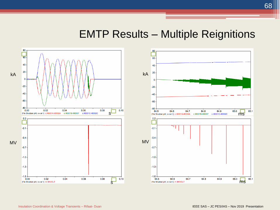
EMTP Results – Multiple Reignitions
ms
kAkA
s
mss
MV MV
Insulation Coordination & Voltage Transients – Rifaat- Duan IEEE SAS – JC PES/IAS – Nov 2019 Presentation
69
Simplification – TRV envelope
TRV Envelope
TRV Envelope
V
ms
Insulation Coordination & Voltage Transients – Rifaat- Duan IEEE SAS – JC PES/IAS – Nov 2019 Presentation
70
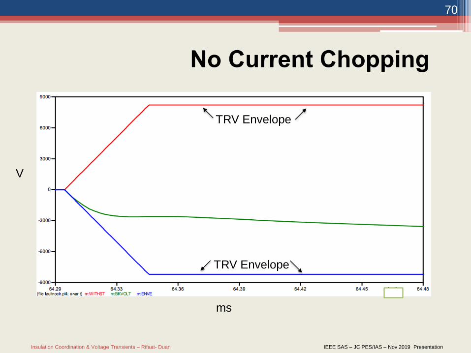
No Current Chopping
TRV Envelope
TRV Envelope
V
ms
Insulation Coordination & Voltage Transients – Rifaat- Duan IEEE SAS – JC PES/IAS – Nov 2019 Presentation
71
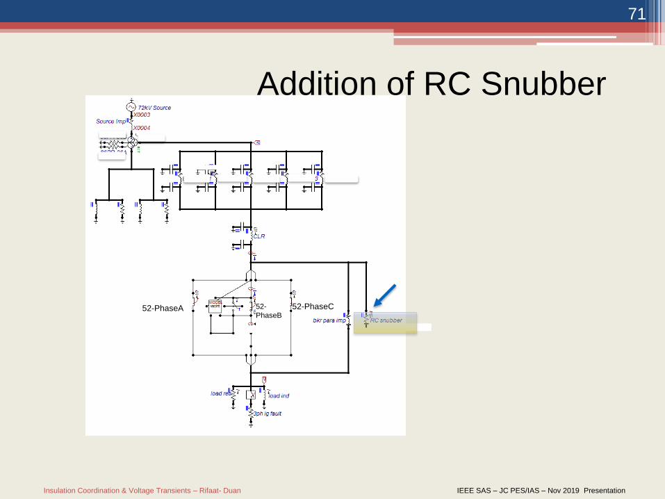
Addition of RC Snubber
52-
PhaseB52-PhaseA 52-PhaseC
Insulation Coordination & Voltage Transients – Rifaat- Duan IEEE SAS – JC PES/IAS – Nov 2019 Presentation
72
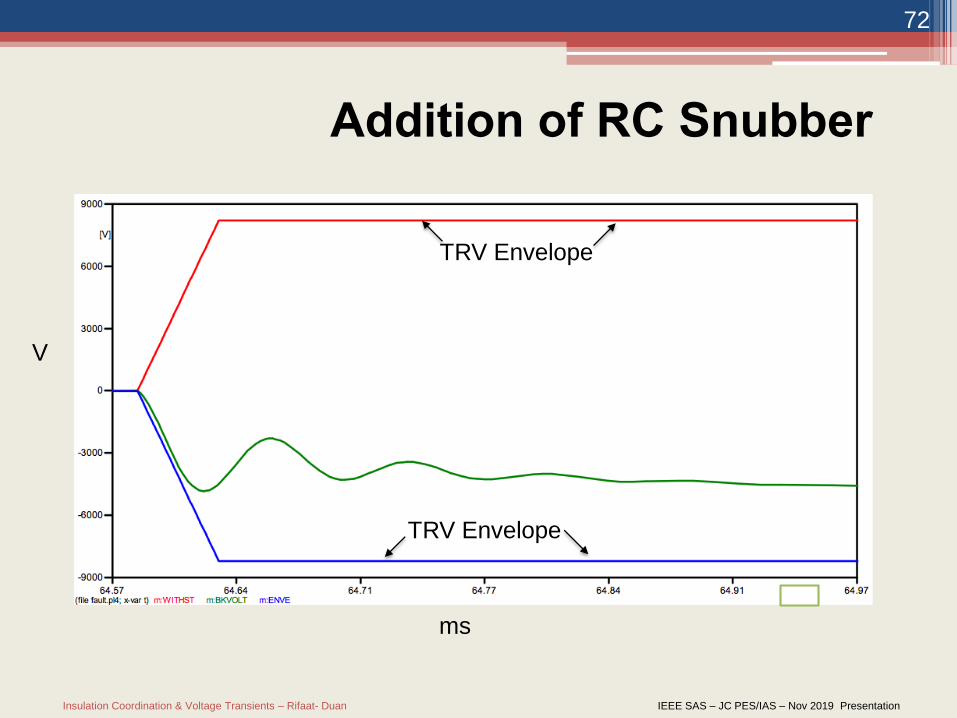
Addition of RC Snubber
TRV Envelope
TRV Envelope
V
ms
Insulation Coordination & Voltage Transients – Rifaat- Duan IEEE SAS – JC PES/IAS – Nov 2019 Presentation
73
When system configuration is altered, transient recovery voltage
(TRV) on breaker may considerably change such that it becomes
outside the acceptable limits. To establish vacuum breaker’s TRV
in a modified system, the Electromagnetic Transient Program
(EMTP) could be used to model the system and the vacuum
breaker and to perform the necessary calculations. Modelling
vacuum circuit breakers shall address current chopping
phenomena as necessary. Current chopping could introduce high
frequency voltage transients which cause the TRV to have high
rate of rise and could bring it out of allowable IEEE established
limits. If required, remedial actions can be taken to bring the TRV
of the breaker to the allowable zone as given by the Standards
Conclusion:
Insulation Coordination & Voltage Transients – Rifaat- Duan IEEE SAS – JC PES/IAS – Nov 2019 Presentation
74
Transient Recovery Voltage (TRV)
Special Case (Short Line Fault)
A special case is the short line fault where the circuit breaker is stressed by thedifference between TRV’s on the line and load side.
…
Insulation Coordination & Voltage Transients – Rifaat- Duan IEEE SAS – JC PES/IAS – Nov 2019 Presentation
75
Case Study – FCLD - Introduction
• In medium voltage (MV) industrial distribution systems power requirements may change over time.
▫ Eg: An equipment is operating more than what it was initially designed for. If a fault was to occur there’s a possibility that:
TRV is greater than the equipment’s design
Fault occurred on an important equipment, which can result to major outages
• Regardless of the reasoning, short circuit current needs to be restricted to something more manageable
Insulation Coordination & Voltage Transients – Rifaat- Duan IEEE SAS – JC PES/IAS – Nov 2019 Presentation
76
FCLD Introduction (Cont.)
• As short circuit current in MV systems are a function of voltage and inductive reactance a way to limit the fault is to increase inductive reactance at fault location.
▫ One way of doing so is using a current limiting reactor
• Current limiting Reactors:
▫ Limits short-circuit current and voltage to a level suitable for installed electrical system
▫ Can be used to allow continuous operation without having to open the circuit
Insulation Coordination & Voltage Transients – Rifaat- Duan IEEE SAS – JC PES/IAS – Nov 2019 Presentation
77
Study and Analysis Approach
Important to study the Switching Transient and Transient
Recovery Voltage (TRV) of how the electrical equipment
characteristics.
EMTP / ATPdraw is a useful program to simulate
transient studies. In this case we used it to study the
characteristics of the current limiting reactor and its’
affect on the overall system.
However, EMTP is not as user-friendly as other power
system programs. Need to model current limiting
reactors as individual components
Insulation Coordination & Voltage Transients – Rifaat- Duan IEEE SAS – JC PES/IAS – Nov 2019 Presentation
78
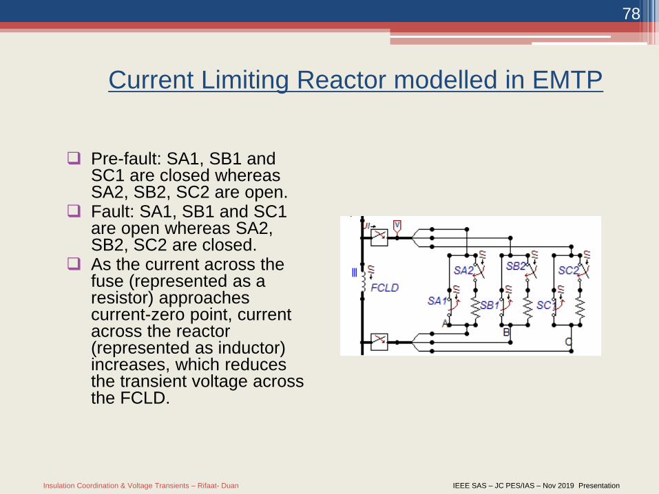
Current Limiting Reactor modelled in EMTP
Pre-fault: SA1, SB1 and SC1 are closed whereas SA2, SB2, SC2 are open.
Fault: SA1, SB1 and SC1 are open whereas SA2, SB2, SC2 are closed.
As the current across the fuse (represented as a resistor) approaches current-zero point, current across the reactor (represented as inductor) increases, which reduces the transient voltage across the FCLD.
Insulation Coordination & Voltage Transients – Rifaat- Duan IEEE SAS – JC PES/IAS – Nov 2019 Presentation
79
Results
The transient voltage across the current limiting reactor
is much smaller than the transient voltage across a
fuse/breaker without current limiting reactor.
If sized properly the current limiting reactor can:
Ensure that the TRV will be within equipment’s
limitations
Allow continuous operation without having to break the
circuit due to a fault.

Insulation Coordination & Voltage Transients – Rifaat- Duan IEEE SAS – JC PES/IAS – Nov 2019 Presentation
80
Lightning Protection for A
Distribution OH Line
Case Study
Insulation Coordination & Voltage Transients – Rifaat- Duan IEEE SAS – JC PES/IAS – Nov 2019 Presentation
81
Part II:
Overhead industrial distribution MV lines
subjected to lightning strikes
• This section discusses
OH distribution lines subjected to Lightning strikes
Flashovers caused by direct strikes and induced
voltages
Possible solutions that can be implemented to
reduce outages caused by lightning strikes
Economics i-e criticality of load vs cost of
implementing these solutions.
Insulation Coordination & Voltage Transients – Rifaat- Duan IEEE SAS – JC PES/IAS – Nov 2019 Presentation
82
Case Study
• System Description:
a. 25kV distribution line located in Northern Alberta
feeding critical facility loads.
b. Feeder passing through flat land with no buildings
and trees in surroundings.
c. Line Configuration: Horizontal arrangement with no
shield wire and surge arresters for lightning
protection.
d. System have experienced outages due to lightning
strikes.
Insulation Coordination & Voltage Transients – Rifaat- Duan IEEE SAS – JC PES/IAS – Nov 2019 Presentation
83
Lightning Flashovers
• Lightning flashovers are caused by either Direct
lightning strikes or induced voltages produced by
lightning strikes on nearby building, trees etc.
• For our 25kV feeder located in Fort McMuarry, direct-
stroke flashovers and induced flashovers in Fort
McMuarry area are estimated (based on methods
described in IEEE STD 1410-2010) to be around 68
Flashovers/100km/year and 2 Flashovers/100km/yr.
Assuming all flashovers cause faults , Total faults= 70
faults/100km/yr.
Insulation Coordination & Voltage Transients – Rifaat- Duan IEEE SAS – JC PES/IAS – Nov 2019 Presentation
84
System Improvement Options
(I) Shielding: Extend pole and add shield wire
(II) Lightning Arresters: Add lightning arrestors every
second pole?
(III) Replace insulators with higher BIL (which would also
help for system that does not have effectively grounded
neutral)
Insulation Coordination & Voltage Transients – Rifaat- Duan IEEE SAS – JC PES/IAS – Nov 2019 Presentation
85
Shield Wire
i. Addition of shield wire provides one of the best solutions to
mitigate outages against direct lightning strikes.
ii. Use of shield wire with shielding angle less than 30 degree and
structure CFO of 225kV (typical 25kV tangent) and ground
resistance of 10 ohms, number of direct hits causing flashover
can be reduced down to 80% (Figure 8, IEEE STD 1410-2010)
iii. However,
o Assumption of 10ohm grounding resistance may not be
accurate. Figure 8 of IEEE STD 1410 maybe used to evaluate
the reduction in shield wire performance due to ground
resistance.
o Back Flashovers
Insulation Coordination & Voltage Transients – Rifaat- Duan IEEE SAS – JC PES/IAS – Nov 2019 Presentation
86
Surge arresters
i. The use of arresters only to protect against direct strokes is not
very effective economically.
ii. However arresters prove to be very effective in reducing the
induced voltage flashovers especially when used to protect pole
with lower insulation levels.
iii. When used in conjunction with an OHSW, the overhead ground
wires divert most of the lightning energy away from phase
conductors and connected equipment, and the arresters limit peak
insulator voltages and reduce back flashover rates more
effectively than improved grounding at every pole, hence, making
OHSW design less dependent on insulation level and grounding.
Insulation Coordination & Voltage Transients – Rifaat- Duan IEEE SAS – JC PES/IAS – Nov 2019 Presentation
87
Summary and Conclusions
• From above analysis:
o Direct lightning strikes are major source of flashovers
based on line vicinity and structure configuration.
o Adding the shielding wire with ground lead grounded at
every pole provides the best possible protection against
the lightning flashovers. However to counter the effects
of back flashovers and induced voltage strikes further
steps shall be taken.
o Use of longer crossarm or fiberglass standoff for
downlead may be used to provide more insulation
between center phase and ground downlead.
o Use of guy strain insulators may be considered.
Insulation Coordination & Voltage Transients – Rifaat- Duan IEEE SAS – JC PES/IAS – Nov 2019 Presentation
88
Summary and Conclusion (continued)
o In cases where the footing resistance at the pole is
higher and improving structure insulation is not possible
the use to surge arresters is recommended
o Pole structures with electrical equipment like cable
terminations, transformers, fuse cut-outs and disconnect
switches shall be protected with surge arresters.
Insulation Coordination & Voltage Transients – Rifaat- Duan IEEE SAS – JC PES/IAS – Nov 2019 Presentation
89
A Brief Discussion on Slow Front Over-
voltage (SFO), Fast Front Over-
voltages (FFO), Very Fast Transient
Over-voltages (VFTO) and Ferro
Resonance
Insulation Coordination & Voltage Transients – Rifaat- Duan IEEE SAS – JC PES/IAS – Nov 2019 Presentation
90
Standards, Books and Key
References

Insulation Coordination & Voltage Transients – Rifaat- Duan IEEE SAS – JC PES/IAS – Nov 2019 Presentation
91
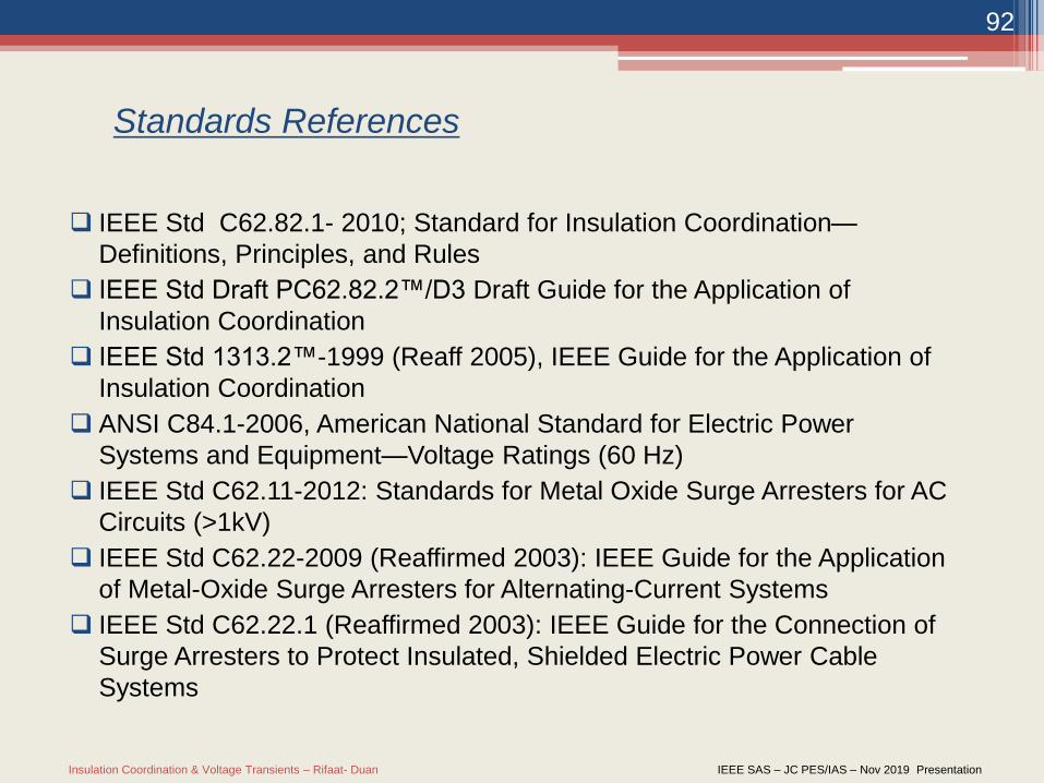
Standards References
IEEE Std C62.82.1- 2010; Standard for Insulation Coordination—
Definitions, Principles, and Rules
IEEE Std Draft PC62.82.2™/D3 Draft Guide for the Application of
Insulation Coordination
IEEE Std 1313.2™-1999 (Reaff 2005), IEEE Guide for the Application of
Insulation Coordination
ANSI C84.1-2006, American National Standard for Electric Power
Systems and Equipment—Voltage Ratings (60 Hz)
IEEE Std C62.11-2012: Standards for Metal Oxide Surge Arresters for AC
Circuits (>1kV)
IEEE Std C62.22-2009 (Reaffirmed 2003): IEEE Guide for the Application
of Metal-Oxide Surge Arresters for Alternating-Current Systems
IEEE Std C62.22.1 (Reaffirmed 2003): IEEE Guide for the Connection of
Surge Arresters to Protect Insulated, Shielded Electric Power Cable
Systems
Insulation Coordination & Voltage Transients – Rifaat- Duan IEEE SAS – JC PES/IAS – Nov 2019 Presentation
92
Standards References
IEEE Std C62.82.1- 2010; Standard for Insulation Coordination—
Definitions, Principles, and Rules
IEEE Std Draft PC62.82.2™/D3 Draft Guide for the Application of
Insulation Coordination
IEEE Std 1313.2™-1999 (Reaff 2005), IEEE Guide for the Application of
Insulation Coordination
ANSI C84.1-2006, American National Standard for Electric Power
Systems and Equipment—Voltage Ratings (60 Hz)
IEEE Std C62.11-2012: Standards for Metal Oxide Surge Arresters for AC
Circuits (>1kV)
IEEE Std C62.22-2009 (Reaffirmed 2003): IEEE Guide for the Application
of Metal-Oxide Surge Arresters for Alternating-Current Systems
IEEE Std C62.22.1 (Reaffirmed 2003): IEEE Guide for the Connection of
Surge Arresters to Protect Insulated, Shielded Electric Power Cable
Systems
Insulation Coordination & Voltage Transients – Rifaat- Duan IEEE SAS – JC PES/IAS – Nov 2019 Presentation
93
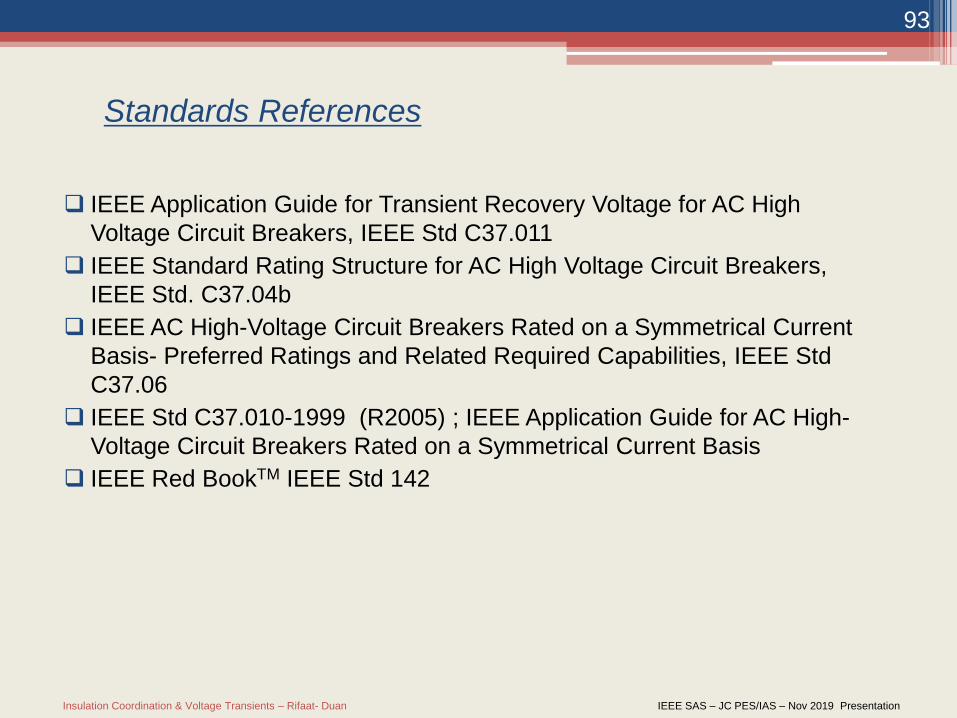
Standards References
IEEE Application Guide for Transient Recovery Voltage for AC High
Voltage Circuit Breakers, IEEE Std C37.011
IEEE Standard Rating Structure for AC High Voltage Circuit Breakers,
IEEE Std. C37.04b
IEEE AC High-Voltage Circuit Breakers Rated on a Symmetrical Current
Basis- Preferred Ratings and Related Required Capabilities, IEEE Std
C37.06
IEEE Std C37.010-1999 (R2005) ; IEEE Application Guide for AC High-
Voltage Circuit Breakers Rated on a Symmetrical Current Basis
IEEE Red BookTM IEEE Std 142
Insulation Coordination & Voltage Transients – Rifaat- Duan IEEE SAS – JC PES/IAS – Nov 2019 Presentation
94
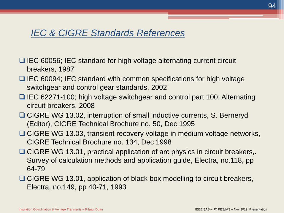
IEC & CIGRE Standards References
IEC 60056; IEC standard for high voltage alternating current circuit
breakers, 1987
IEC 60094; IEC standard with common specifications for high voltage
switchgear and control gear standards, 2002
IEC 62271-100; high voltage switchgear and control part 100: Alternating
circuit breakers, 2008
CIGRE WG 13.02, interruption of small inductive currents, S. Berneryd
(Editor), CIGRE Technical Brochure no. 50, Dec 1995
CIGRE WG 13.03, transient recovery voltage in medium voltage networks,
CIGRE Technical Brochure no. 134, Dec 1998
CIGRE WG 13.01, practical application of arc physics in circuit breakers,.
Survey of calculation methods and application guide, Electra, no.118, pp
64-79
CIGRE WG 13.01, application of black box modelling to circuit breakers,
Electra, no.149, pp 40-71, 1993
Insulation Coordination & Voltage Transients – Rifaat- Duan IEEE SAS – JC PES/IAS – Nov 2019 Presentation
95
Book References
Andrew Hileman “Insulation Coordination for Power Systems, CRC Press 1991
Farouk Risk & Giao Trinh “High Voltage Engineering” CRC Press 2014 Abdel-Salam, Anis, El-Morshedy & Radwan “High-Voltage Engineering;
Theory & Practice” Second Edition, CRS 2000 Ametani, Nagaoka, Baba & Ohno “Power System Transients; Theory and
Applications” CRC 2014 Hadad & Warne “Advances in High Voltage Engineering” IET Power and
Energy Series 40, paperback edition 2009Martinez-Velasco, Juan A. (Editor); Power System Transients; Parameter
Determination,, CRC Press 2010 Slade, P.G., “The Vacuum Interrupter, Theory, Design and Applications”
CRC Press, 2008 Slade, P.G. (Editor), “Electrical Contacts, Principles and Applications”, 2nd
Edition, CRS Press, 2008
Insulation Coordination & Voltage Transients – Rifaat- Duan IEEE SAS – JC PES/IAS – Nov 2019 Presentation
96
References: Articles
• Rifaat, R, Marten, K, Ahmed, A and Change, K, “Addressing Voltage Transients in
Medium Voltage Industrial Electrical Systems; When and How?” A presentation Prepared
for ESTMP Workshop, Calgary, , March 2016
• Kondala Rao B., and Gajjar, G., “Development and Application of Vacuum Circuit
Breaker Model in Electromagnetic Transient Simulation”
• Kosmac J. and Zunko, P. “A Statistical Vacuum Circuit Breaker Model for Simulation of
Transient Over voltages” IEEE Transactions on Power Delivery, Vol. 10, No. 1, January
1995
• McDermit, D.C., Shipp, D.D., Dionise, T.D., and Lorch, V., “Medium-Voltage Switching
Transient-Induced, Potential Transformer Failures: Prediction, Measurement, and
Practical Solutions”, IEEE Transactions on Industry Applications, Vol. 49, No. 4,
July/August 2013
• Murano,M., Fujii T., Nishikawa,H., Nishiwaki,S., and Okawa, M., :”Voltage Escalation
in Interrupting Inductive Current”, a paper presented to the PES Summer Meeting &
EHV/UHV Conference, Vancouver, B.C., Canada, July 15-20, 1973.
• Murano,M., Yanabu, S., Ohashi, H., Ishizuka, H., and Okazaki, T., “Current Chopping
Phenomena of Medium Voltage Circuit Breakers”, IEEE Transactions on Power
Apparatus and Systems, Vol. PAS-96, no. 1, January/February 1977
• Nishikawa H. Masuda, S.,Yokokura, K., Miyazawa, T., Honma, T., Mishima, T. and Ike, M.
“Vacuum Circuit Breakers Switching Surge Influence on Low Voltage Instrumentation
Circuits”, IEEE Transactions on Power Apparatus and Systems, Vol. PAS-102, No. 7,
July 1983
Insulation Coordination & Voltage Transients – Rifaat- Duan IEEE SAS – JC PES/IAS – Nov 2019 Presentation
97
References: Articles
• Ospina, G. Idarraga, Cubillos, D. and Ibanez, L., “Analysis of Arcing Fault
Models” IEEE Paper
• Popov, M., Acha E., “Overvoltages due to Switching off an Unloaded
Transformer with a Vacuum Circuit Breaker”, IEEE Transactions on Power
Delivery, Vol. 14, No. 4, October 1999
• Popov, M., van der Sluis, L., “Comparison of two Vacuum Circuit Breaker Arc
Models for Small Inductive Current Switching” IEEE 19* International
Symposium on Discharges and Electrical Insulation in Vacuum
• Popov, M., van der Sluis,L., Smeets. R.P.P., and Roldan,J.L., “Analysis of Very
Fast Transients in Layer-Type Transformer Windings” IEEE Transactions on
Power Delivery, Vol. 22, No. 1, Jan 2007
• Shores, R B. and Phillips, V. E., “High Voltage Vacuum Circuit Breakers”, IEEE
Transactions on Power Apparatus and Systems, vol. PAS-94, no. 5,
September/October 1975
• Smugala, D., Piasecki, W, Ostrogorska, M., Fulczyk, Florkowski, M, and Kłys P.:
“Protecting distribution transformers against Very Fast Transients due to
switching operation” Modern Electric Power Systems 2010, Wroclaw, Poland
Insulation Coordination & Voltage Transients – Rifaat- Duan IEEE SAS – JC PES/IAS – Nov 2019 Presentation
98
References: Articles• Soloot, A. H., Hoidalen, H. K. “Upon The Impact of Power System and Vacuum
Circuit Breaker Parameters on Transient Recovery Voltage”
• Sorensen, R. W., Mendenhall, H.E., “Vacuum Switching Experiments at
California Institute of Technology” Presented at the Pacific Coast Convention of
the Α. I. E. E., Salt Lake City, Utah, Sept. 6-9,1926
• Vahidi, B., Tavakoli, M. R. B., Hashemifar S.H. and Raahemifar K. “Transient in
the Operation of Induction and Synchronous Motors with Vacuum Switches”
• van der Sluis, L. and Rutgers, W.R., “The Comparison of Test Circuits with Arc
Models
• Wróblewski, Z. and Budzisz J., “Switching Effects in Capacity Circuits with a
Vacuum Switch” Paper presented to Modern Electric Power Systems 2010,
Wroclaw, Poland