Product Safety Considerations for Insulation Coordination...
30
Product Safety Considerations for Insulation Coordination of Low- Voltage Equipment Scott Aldous, Compliance Engineer
Transcript of Product Safety Considerations for Insulation Coordination...

Product Safety Considerations for Insulation Coordination of Low-Voltage Equipment
Scott Aldous, Compliance Engineer

What is Insulation Coordination?
• From IEC 60664-1, Edition 1.2:
• So what does that mean in English?
What is Insulation Coordination? (cont.)
• From the IEEE Power and Energy Society, Surge Protective DevicesCommittee*:
• COORDINATION OF INSULATION The process of correlating the insulation strengths of electric equipment with expected overvoltages and with the characteristics of surge protective devices: see ANSI 92.1–1982[C62.2–1987 & C62.22–1991]
*Source: http://grouper.ieee.org/groups/spd/html/terms_c.html

What is Insulation Coordination? (cont.)
From Klaus Stimper:
“Insulation co-ordination implies the selection of the electric insulation characteristics of equipment with regard to is application and in relation to its surroundings.”
Source: K. Stimper, ”The physical fundamentals of low-voltage insulation co-
ordination”, VDE-Schriftenreihe, Vol. 57, Berlin, Offenbach vde-verlag1991.

First Step of Insulation Coordination

First Step of Insulation Coordination (cont.)
• Define the Environment!
• Parameters that must be defined include:
• Overvoltage Category• Pollution Degree (Macro and
Micro Environments)• Working Voltages• Mains Configuration if
Connection to AC Mains Present
• Operating Altitude

Overvoltage Category
• At STP, air breaks down at approximately 3kV/mm• According to IEC 60950-1, 2nd Ed., for a standard office environment, the
minimum air gap between 120Vac mains and ground shall be 1.0mm.
Why?

Transient Overvoltages
*Table from IEC 60950-1, 2nd Edition

Transient Overvoltages, IEC 60664-1
*Table from IEC 60664-1, Ed. 1.2

Six (k) of One, Half a Dozen (k) of AnotherIEC Approach (as explained by Klaus Stimper)
• Basis of tables in IEC 60664-1• Literature study of more than 50 publications on transient overvoltages measured in European 230/400V
systems (voltages induced by lightning strikes)• Conclusion of study was that 6kV was rarely exceeded• Surge arrestors along overhead lines in Germany are rated 2kV• 1kV drop is assumed resulting from earth resistance of the arrestor• Resulting 3kV surge could be doubled by reflections/constructive interference
IEEE Approach (as explained by Francois Martzloff)• Analysis of data led to 3 categories relating # of surges/year and voltages• Categories are Low, High and Extreme Exposure• Noted that 6kV is typical wiring device sparkover• 6kV indicated as valid for indoor systems
• Both approaches concede that 6kV is not worst case, but higher voltages are improbable.• IEC approach appears to have gained more widespread acceptance.
Sources: K. Stimper, ”The physical fundamentals of low-voltage insulation co-ordination”, VDE-
Schriftenreihe, Vol. 57, Berlin, Offenbach vde-verlag 1991.F. Martzloff, “Protective Devices, Systems and Methods: Transient Overvoltage Protection
in the Undefined Real-World Environment”, Solid State PowerConversion, Oxnard, 1979.

Definition of Overvoltage Categories– Equipment of overvoltage category IV is for use at the origin of the installation.NOTE Examples of such equipment are electricity meters and primary overcurrent protection equipment.
– Equipment of overvoltage category III is equipment in fixed installations and for cases where the reliability and the availability of the equipment is subject to special requirements.
NOTE Examples of such equipment are switches in the fixed installation and equipment for industrial use with permanent connection to the fixed installation.
– Equipment of overvoltage category II is energy-consuming equipment to be supplied from the fixed installation.
NOTE Examples of such equipment are appliances, portable tools and other household and similar loads.
– Equipment of overvoltage category I is equipment for connection to circuits in which measures are taken to limit transient overvoltages to an appropriately low level.
* Source: IEC 60664-1, Ed. 1.2, Clause 2.2.2.1.1

Pollution Degree
– Pollution degree 1No pollution or only dry, non-conductive pollution occurs. The pollution has
no influence.– Pollution degree 2Only non-conductive pollution occurs except that occasionally a temporary
conductivity caused by condensation is to be expected.– Pollution degree 3Conductive pollution occurs or dry non-conductive pollution occurs which
becomes conductive due to condensation which is to be expected.– Pollution degree 4Continuous conductivity occurs due to conductive dust, rain or other wet
conditions.
* Source: IEC 60664-1, Ed. 1.2, Clause 2.5.1

Historical Background• A paper was published in 1983 detailing results of collaborative
experiments in the USA and Germany.• Climatic conditions and measurements of corrosive gases in the air were
taken at various sites, along with chemical analysis of test specimens’surface layers.
• Insulation resistance testing was performed to observe the influence of environmental conditions on insulation performance.
• IEC 60664-1 also draws from other studies.
• Summary of paper: The paper reports on a research project with the goal of ascertaining the effects of environmental pollution on insulating materials, to simulate these effects in the laboratory, to determine the insulating properties of synthetic materials commonly used in electrical engineering and thus to provide creepage distances for the design of products in the 0 to 1000 V range. As the first phase of this project, test boards with a total of over 24000 test positions are being subjected to various environmental conditions in locations throughout Germany and in two locations in the United States. Surface tracking and interelectrode resistance will be monitored periodically throughout the aging period; the dust, which settles on the test units, will be analyzed at the conclusion of the tests. Comparative tests in an artificial industrial atmosphere are intended to simulate the field trials at an accelerated pace.
• Schau, P.V.; Middendorf, W.H., “An International Research Project to Determine New Dimensioning Rules for Creepage Distances”, Electrical Insulation, IEEE Transactions on Volume EI-18, Issue 2, April 1983 Page(s):158 - 162

Effect of Humidity on Over-Surface Insulation
Source: K. Stimper, ”The physical fundamentals of low-voltage insulation co-ordination”, VDE-Schriftenreihe, Vol. 57, Berlin, Offenbach vde-verlag 1991.
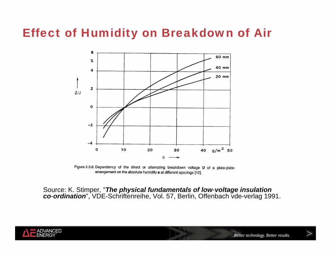
Effect of Humidity on Breakdown of Air
Source: K. Stimper, ”The physical fundamentals of low-voltage insulation co-ordination”, VDE-Schriftenreihe, Vol. 57, Berlin, Offenbach vde-verlag 1991.

Effect of Corrosive Components of Air
• Concentrations of SO2, NO, NO2, Cl-, F- and O3 measured as part of the data collection effort.
• In all cases, concentrations were significantly (orders of magnitude) below those concentrations that caused measurable insulation deterioration in the lab after several weeks.
• Deterioration is caused by slow chemical reactions.• There was no correlation between data of corrosive gases to the chemical
analysis of the pollution deposition on the test specimens.• IEC 60664-1 disregarded the effect of corrosive gases in its requirements.
Deterioration is considered mainly due to dust.

Effect of Dust Deposition on Insulation
Source: K. Stimper, ”The physical fundamentals of low-voltage insulation co-ordination”, VDE-Schriftenreihe, Vol. 57, Berlin, Offenbach vde-verlag 1991.
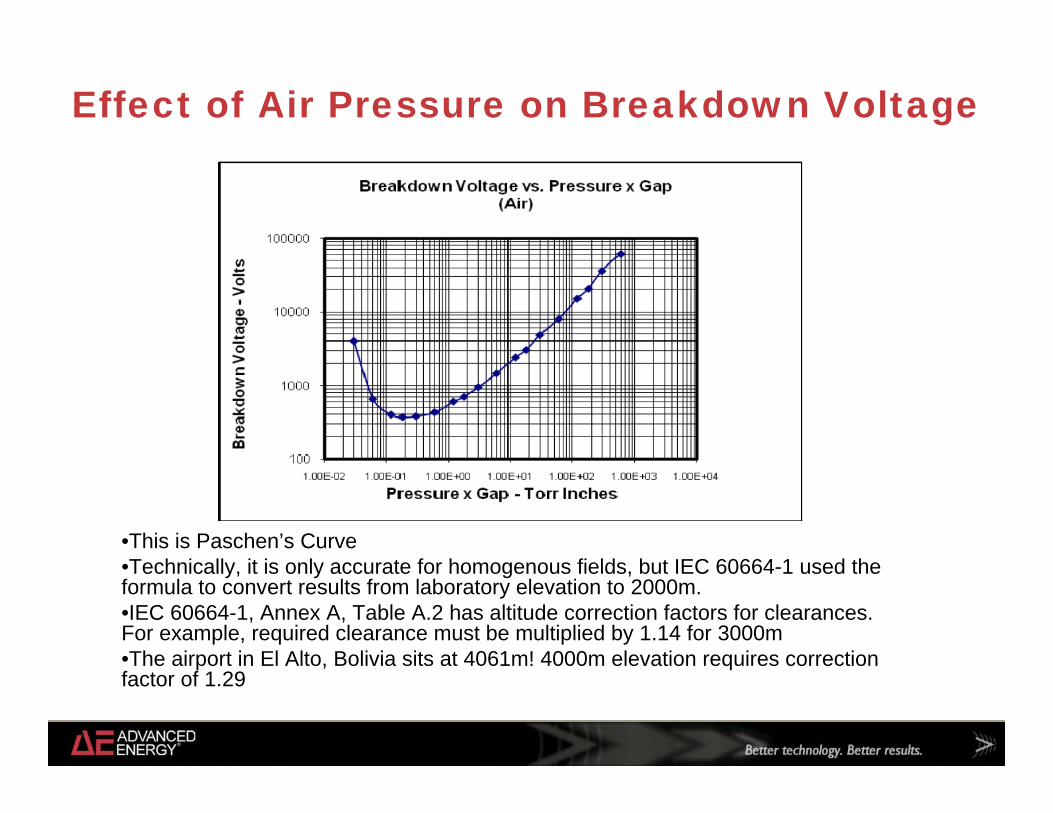
Effect of Air Pressure on Breakdown Voltage
•This is Paschen’s Curve•Technically, it is only accurate for homogenous fields, but IEC 60664-1 used the formula to convert results from laboratory elevation to 2000m.•IEC 60664-1, Annex A, Table A.2 has altitude correction factors for clearances. For example, required clearance must be multiplied by 1.14 for 3000m•The airport in El Alto, Bolivia sits at 4061m! 4000m elevation requires correction factor of 1.29

Clearance
• Clearance – shortest distance in air between two conductive parts• Also referred to as Through-Air Spacings (in UL speak)• Major factors affecting clearance:
• Air Pressure (Altitude)• Temperature (if wide variation)• Overvoltage Category• From product safety evaluation
point of view, working voltage• Homogenous vs. Inhomogenous
Fields• Temporary overvoltages or
recurring peak voltages
* Source for Photo: http://www.electricalforensics.com/testing/testing.htm

Creepage
• Creepage Distance – shortest distance along the surface of the insulating material between two conductive surfaces
• Also referred to as Over-Surface Spacings (in UL speak)• Major factors affecting creepage
• Pollution Degree• Humidity• Dust deposition
• Material Properties (CTI)

Comparative Tracking Index (CTI)
•Tracking occurs when a surface leakage current is interrupted due to drying out of surface liquid, can cause progressive formation of conductive paths on surface of insulating material.•CTI is relative measure of material propensity for tracking•Inorganic materials (such as glass, ceramics) do not track•50 drops of 0.1% ammonium chloride solution dropped onto material, voltage measured for a 3mm thickness•IEC standards classify materials according to material groups•UL standards classify materials according to the PLC 5IIIbLess than 100
4IIIb100 through 174
3IIIa175 through 249
2IIIa250 through 399
1II400 through 599
0I600 and greater
UL PLCIEC Material Group
CTI (in volts)

Basic Approach of Electrical Product Safety
• Assumption applied to Electric Shock Hazards:• Two levels of protection must be provided to protect operators from electric
shock.• Five different types of insulation are defined:
• Functional Insulation – insulation between conductive paths which is necessary only for the proper functioning of the equipment
• Basic Insulation – insulation applied to live parts to provide basic protection against electric shock
• Supplementary Insulation - independent insulation applied in addition to basic insulation, in order to provide protection against electric shock in the event of a failure of basic insulation
• Double Insulation – insulation comprising both basic insulation and supplementary insulation
• Reinforced Insulation - single insulation system applied to live parts, which provides a degree of protection against electric shock equivalent to double insulation
• Protective Earthing is also considered a single level of protection.
Component Selection
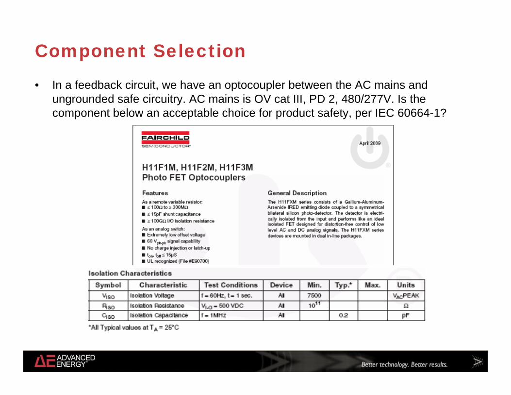
• In a feedback circuit, we have an optocoupler between the AC mains and ungrounded safe circuitry. AC mains is OV cat III, PD 2, 480/277V. Is the component below an acceptable choice for product safety, per IEC 60664-1?
Component Selection (Cont.)
• Component is UL Recognized, but it is not clear from the UL file what isolation voltage it is approved for.
• Assuming UL rating is identical to spec (7500Vpk isolation), then:• Impulse rating for this mains circuit is 4000Vpk per table 1• Impulse test voltage would be 4800Vpk at sea level per table 5• Assume manufacturer spec is tested at sea level• If product used up to 2000m, then must apply correction factor of 1.28 (table 8,
inverse of 0.784) – gives 6144Vpk impulse test voltage• Looks OK, right?

Component Selection (Cont.)
• But mains to ungrounded safe circuitry requires Double or Reinforced Insulation. Test voltage must be based on next higher step impulse rating when based on standard impulse value. So impulse rating used must be 6000V, not 4000V.
• From table 5, impulse test voltage is 7300Vpk• Applying correction factor for altitude, 7300Vpk * 1.28 = 9344Vpk required
impulse test voltage
• Component is not acceptable for the application
• Other Considerations:• Thin Film Insulation• Component Spacings Requirements vs. End Product Spacings
Requirements• Manufacturer Voltage Ratings

Can’t we just hipot it?
Your product safety engineer’s favorite question. Go ahead. Ask.
• Clearances can be evaluated by impulse or dielectric strength testing, simulating resistance to transients.
• Solid insulation can be evaluated by dielectric strength testing
• IEC 60664-1 requires clearances to be tested if they are below the values stipulated for inhomogenous fields.
• UL 840 has a similar provision• No flashover breakdown allowed• IEC 60664-1 also indicates testing for partial
discharge and high frequency dielectric heating, but few product safety standards include these tests as requirements.

Combination of Insulating Elements
• Insulation consists of clearance, creepage and/or solid insulation• What do to if a single point of insulation comprises multiple elements?• Example: A trace near the edge of a PCB is a secondary circuit with
1000Vrms working voltage, pollution degree 2, overvoltage category II, 480/277V 3 phase mains, 1.0mm from trace to edge of board, then 0.5mm from edge of board through air to UL Recognized green/yellow protective bonding jumper rated 600V
• Solid Insulation – rated 600V• Clearance Requirement (based on 2500V impulse) – 1.5mm• Creepage Distance Requirement – 5.0mm• Is this system compliant to the requirements of IEC 60664-1?

Combination of Insulation Elements (Cont.)
• Solid Insulation – 60% of required voltage rating• Clearance – 33% of required distance• Creepage – 20% of required distance• Total: 113%
But this system is not compliant!
• Air gap is less than 1mm (PD 2), so is treated as creepage.• Solid Insulation – 60%• Clearance – 0mm – 0%• Creepage – 1.5mm – 30%• Total: 90%

Q&A

© Advanced Energy Industries, Inc. All Rights Reserved.
NasdaqGM: AEISwww.advanced-energy.com