
INSTRUMENT RELIABILITY NETWORK
30
INSTRUMENT RELIABILITY NETWORK Handbook February 4, 2018 Instrument Reliability Network Mary Kay O’Connor Process Safety Center Chemical Engineering Department Texas Engineering Experiment Station Texas A&M University System 3122 TAMU College Station, Texas 77843-3122 ************* (979) 845-3489 http://psc.tamu.edu
Transcript of INSTRUMENT RELIABILITY NETWORK
INSTRUMENT RELIABILITY NETWORK Handbook
February 4, 2018
Instrument Reliability Network
Mary Kay O’Connor Process Safety Center
Chemical Engineering Department
Texas Engineering Experiment Station
Texas A&M University System
3122 TAMU
College Station, Texas 77843-3122
*************
(979) 845-3489
http://psc.tamu.edu
TABLE OF CONTENTS
1 CALL TO ACTION ............................................................................................................................. 3
2 STEERING COMMITTEE COMPOSITION ................................................................................... 4
3 DATA MANAGEMENT AND PROCESSING AT MKOPSC ........................................................ 5
4 PROJECTS ........................................................................................................................................... 6
4.1 CHARTERS ...................................................................................................................................... 6
4.2 HISTORY .......................................................................................................................................... 7
4.3 METHODOLOGY ................................................................................................................................. 7
4.4 PROCESS FOR MODIFYING CHARTERS ............................................................................................... 8
5 DATA ACCESS RIGHTS .................................................................................................................... 8
5.1 THE RIGHT TO REQUEST THE COMPLETE RAW DATA SET................................................................... 9
5.2 DELETION OF DATA ........................................................................................................................... 9
6 DATA SUBMITTAL TO IRN ............................................................................................................. 9
7 DATA PREPARATION, SUBMISSION, AND HANDLING PROTOCOL ................................ 12
7.1 DATA SUBMITTAL PROCESS ............................................................................................................ 12
7.2 QUALITY CONTROL GUIDELINES .................................................................................................... 14
8 FUTURE EFFORTS TO SUPPORT STANDARDIZED DATA TAXONOMIES ...................... 15
9 DATA ANALYSIS AND CALCULATION OF MEASURABLE QUANTITIES ........................ 15
APPENDIX A – IRN CONTACT INFORMATION ............................................................................. 17
APPENDIX B MUTUAL NON-DISCLOSURE AGREEMENT ......................................................... 18
APPENDIX C - PROJECT CHARTER ................................................................................................. 23
APPENDIX D - QUALTRICS INSTRUCTIONS .................................................................................. 24
APPENDIX E - ALGORITHM FOR ANALYSIS ................................................................................ 27

3
1 CALL TO ACTION
Each production unit is controlled by hundreds if not thousands of field devices that detect current
process conditions and take action as necessary to sustain normal production and product quality.
Poor reliability of fields devices significantly lowers process availability, increases maintenance
costs, and contributes to process safety incidents. High reliability organizations have less incidents
and better financial performance than those who tolerate poor instrument reliability.
Two challenging aspects to improving instrument reliability are the limited public domain failure
data with which to benchmark site performance and the relevance of available data to actual in-
service equipment. The intent of the Instrument Reliability Network (IRN) effort is to ease this
challenge through the development of a practical data taxonomy and through multiple users
contributing failure data in different applications. Data collection is covered by a non-disclosure
agreement (Appendix B)
IRN is a collaborative effort supported by the Mary Kay O'Connor Process Safety Center
(MKOPSC). The IRN Steering Committee is populated by representatives from process industry
users. The IRN Steering Committee approves all project charters and submits the requested data
to ensure project success.
IRN MISSION AND Vision
To share historical information and lessons learned to minimize environmental harm, improve
industry safety, maximize asset performance, and reduce maintenance costs through better
lifecycle management of instrumentation and controls applied in the process industry
Participation in IRN allows users to benefit from a collaborative effort that is directed at improving
the instrument reliability in critical applications. IRN’s mission is to:
1) Benchmark current performance of instrumentation and controls in process industry
applications.
2) Define a common taxonomy to support consistent collection of quality data from
maintenance and proof test activities.
3) Share lessons learned in improving instrumentation and controls reliability.
4
2 STEERING COMMITTEE COMPOSITION
The IRN Steering Committee consists of representatives of user companies and MKOPSC. IRN
provides multiple networking opportunities throughout the year, where Steering Committee
members discuss challenges to instrument reliability that need to be met with comprehensive
solutions. The IRN steering committee:
a. Establishes a business case for data collection during project development
b. Develops the taxonomy necessary to track and trend performance at a cost-effective
granularity
c. Documents a data collection methodology to ensure consistent, high quality data
d. Shares the lessons learned during project execution
e. Communicates the value of an instrument reliability program
f. Supports the IRN conference held in January on the Texas A&M University campus
Any representative from a process industry company may become a member of the Steering
Committee. Any company wishing to participate should contact one of the people listed in
Appendix A. Each member company can assign as many participants in IRN as desired. The
Steering Committee accepts process industry representatives who are supportive of IRN’s mission.
Member representatives volunteer to be part of the Data Acquisition team based on their interest
in particular projects. The Data Acquisition Team is responsible for data collection, preparation,
and communication with IRN. The structure and number of members of Data Acquisition Team is
determined by the project charter.
Successful reliability tracking depends on having a practical taxonomy for data collection,
developing a process to ensure actionable data is collected, and getting support from
management and maintenance. Achieving success requires that each of these be addressed as part
of this effort:
Taxonomy: A taxonomy is established in each project charter. Generally, the taxonomy
follows the structure of ISO 14224 and will expand over time as the IRN Steering
Committee determines that there is business value in additional data fields.
Quality Assurance: Quality assurance is a challenge – both in the project charter
development and in the site implementation. As data is collected and analyzed, it can
become apparent that not everyone is interpreting the project charter in the same way or
that collection methods are not yielding a consistent measure of field performance.

5
Actionable data that yields business value requires that the IRN Steering Committee
consider how the written charters enable project success.
Business Value: The concept of business value is referred to repeatedly in this document
to reinforce that the IRN Steering Committee is committed to projects that will yield
tangible benefits to the participants. The goal is not simply to get data for the sake of data,
but to get data that can lower the cost of ownership of instrumentation and controls. Every
project should generate information that drives reliability improvement. There is
significant value to having more accurate and reliable data, but ultimately participation in
IRN helps users reduce losses and down time, enhance their overall safety performance,
and improve their business.
Figure 1: Work and Data Flow within IRN
3 DATA MANAGEMENT AND PROCESSING AT MKOPSC
MKOPSC is responsible for database management and providing an interface to the IRN database
that can be utilized effectively by member companies. The Data Management and Processing
Group, led by the Associate Director of MKOPSC (Appendix A), is responsible for data quality
check, process, storage, and disseminate. This Group is also responsible for all communication
between IRN and member companies. The structure and number of members of the Data
Management and Processing Group is determined by MKOPSC based on project load and funding.

6
The Data Management and Processing group at MKOPSC plays an essential role on the data
submission process. MKOPSC has made every attempt to ensure anonymity of member
companies. Therefore, to accomplish this, there are three distinct and mutually exclusive teams
working at MKOPSC:
1) MKOPSC Top Management includes the Associate Director of MKOPSC (Appendix A)
and a post doctorate assistant, neither of whom are part of the other two teams. This team
has three main functions: data anonymity assurance, management of company self-
identification codes, and communication with member companies. MKOPSC top
management is also responsible for giving access to the restricted member area to member
companies that have contributed data.
2) Quality Control team staffed by graduate students who are not part of Data Analysis team.
Their main responsibilities are to manage the raw data (after contact information is
removed), keep track of dataset batch ID, and perform quality control analysis.
3) Data Analysis Team staffed by graduate students who are not part of Quality Control
team. Their main responsibilities involve managing raw datasets after quality control
analysis is performed, conducting statistical analysis and summarizing the results in a
report. Once the analysis is conducted, Data Analysis team will share the findings to
member companies via restricted member area.
4 PROJECTS
4.1 CHARTERS
Projects can be proposed to the IRN Steering Committee by any member using the project charter
form (Appendix C). Project charters are supported by a business case and can be initiated based
on the interest of at least 3 members. This approach is intended to allow the IRN Steering
Committee to grow the taxonomy as necessary to achieve business value. It is acknowledged that
arguments can be made that “everything” should be collected. However, “everything” does not
lead to business value, so the IRN Steering Committee will focus on minimizing the taxonomy
complexity.

7
4.2 HISTORY
Project 1 Phase 1 (2014 – 2016) – Phase 1 was completed on June 2016. This study evaluated
the Mean Time Between Corrective Maintenance for single and dual element pressure transmitters.
The results of this were presented on June 22, 2016 to IRN. The study found that the failure rate
was bi-modal in nature. Due to the limited granularity in this study, it was not possible to identify
variables which could have correlated with the bimodal failure rate distribution, so Phase 2 was
initiated.
Project 1 Phase 2 (2017 - ongoing) – Phase 2 focuses on potential variables which may correlate
to the bimodal distribution found in Phase 1 study for single and dual sensing pressure transmitters.
Project 2 Phase 1 (2017 – ongoing) – Phase 1 focuses on the Mean Time Between Corrective
Maintenance for control and block valves. The Steering Team is working to finalize the taxonomy.
4.3 Methodology
The project methodology is divided in 3 parts:
1) Project initiation
2) Project execution
3) Project closure
4.3.1 Project Initiation
Projects will be selected based on the following criteria:
1) Member Interest
2) Number of new projects which MKOPSC-IRN can support
4.3.2 Project Execution
Project execution typically follows two phases:
1) Pilot Phase – During the pilot phase, team members work with companies who have agreed
to submit data to validate the charter scope in terms of achievability of target metrics for
the following:

8
a. Standardize Data – Can data be codified consistent with the project charter and
existing IRN documentation? Are any additions or clarifications of existing IRN
documentation required to execute the study phase?
b. Assess Data Quality – What data quality is available? Are the project metrics at a
level of detail consistent with the data quality anticipated to be submitted?
c. Validation of Member Interest – Are 3 companies beyond the pilot phase membership
willing to support the project with data.
d. Refine Project Charter – With the above information, the project charter is clarified.
The project charter is an “evergreen” document that is updated as the project
progresses to reflect current efforts.
2) Study Phase – The study phase is the period where companies interested in submitting data
do so. The study phase is defined in the project charter and can be extended as needed to
ensure adequate data for analysis.
4.3.1 Project Closure
Following the completion of the project, the project metrics are generated and a report is presented
to the Steering Committee. If the results satisfy the charter requirements, the report is accepted as
final and the project is closed. If the results are unsatisfactory, the Steering Committee may choose
to initiate another phase of the project to gather additional data.
4.4 Process for Modifying Charters
Requests to modify a project charter can be submitted to the IRN Steering Committee during any
project stage. Changes may be needed because of issues identified during roll-out, initial data
collection, and project execution. Requests are evaluated by the IRN Steering Committee and
either accepted or rejected.
5 DATA ACCESS RIGHTS
All data submitted to MKOPSC-IRN is stripped of company identifiers. The section titled, Data
submittal to IRN, details the process. The main limitation with membership in IRN is that only
data contributors to a specific project have access to the raw data collected through that project.
All members receive the project results.

9
5.1 The right to request the complete raw data set
Member companies who contribute raw data have the right to request the complete raw data sets.
Raw data sets will only be released after the submittal of a minimum of 3 data sets.
5.2 Deletion of data
Upon request by a member company, specified data associated with that company can be deleted
from the database. Data deletion will follow the process indicated below:
1) Request data deletion: A data member contacts MKOPSC (Appendix A) and specifies the
scope of deletion.
2) Notice of intent to delete data from the database: Following the request, MKOPSC-IRN
will communicate to the membership the scope of the deletion and the targeted date for the
deletion. If objections are made to the data deletion, MKOPSC-IRN will schedule a
conference call with the Steering Committee so that concerns may be addressed.
3) Data Deletion from the database: Data is deleted from the database after concurrence from
the IRN Steering Committee.
6 DATA SUBMITTAL TO IRN
Data is transferred from member companies to MKOPSC before being converted into anonymized
data for the IRN database. The protocol consists of six main steps:
Step 1 - Data preparation at Member Company
Step 2 - Data submission to MKOPSC
Step 3 – Anonymity Assurance
Step 4 - Data quality control at MKOPSC
Step 5 - Data analysis at MKOPSC
Step 6 - Data publication
Figure 2 illustrates the general scheme of data handling. The process starts with member
companies preparing datasets and submitting them either on-line (Appendix D) or via mail
(Appendix A). MKOPSC top management receives the dataset and keeps it for a period of 7 days
before removing contact information and transferring to the QC team. During this time frame,
companies can request deletion without submission of an official form (see Section 5.2). After the

10
7 days, the QC team receives the dataset and executes the quality control analysis. If a dataset
fails quality control, QC team will communicate the failure to MKOPSC Top Management, which
will subsequently contact the corresponding member company; otherwise, the DA team will
receive the dataset.
All documents will be shared with contributing companies through the restricted member area.
Access will be given to every member that has at least one data set approved by the DA team. This
includes reports, conference presentations, and raw dataset (without contact information). Reports
containing summarized analysis will be made available to the public via the IRN webpage.

11
Figure 2. General scheme of data handling protocol for IRN database

12
7 DATA PREPARATION, SUBMISSION, AND HANDLING PROTOCOL
7.1 Data Submittal Process
Successful data submission depends on effective communication. Each member company is asked
to assign two persons, a primary and a secondary, to handle all communication with MKOPSC top
management during the data submission step. Companies should contact MKOPSC top
management (Appendix A) for any issue encountered during data submittal.
7.1.1 Step 1- Prepare Your Data Submittal
Reliability data are prepared for submittal by IRN member companies following an approved
project charter. Data must be submitted in the approved Excel workbook which provides detailed
data expectations. This workbook contains instructions, the data submittal form, and an example
of the expected data type.
7.1.2 Step 2 - Get Your Anonymous Reference Number for the Project
Each dataset submitted by member companies is assigned a reference number having three
sections: (1) Company code; (2) Company specified code (e.g., location code and plant code); and
(3) IRN batch ID. As an example, a data set is named as follows:
1) Company code: The code is for company self-identification. This eight-digit number is
produced by a built-in random number generator the first time data is contributed, that code
is then reserved for that company. Records of the reserved codes are kept in an internal
server which is not available to anyone beyond that of MKOPSC top management. To
retrieve a missing company code, the member company must make a report to MKOPSC
top management. MKOPSC Top Management will evaluate the request.
2) Company specified code: This code is specified by member companies to distinguish
different submitted datasets. For example, the first four digits might be used for location
12345678 - 1234 - 1234 - 000001
Company code Company specified Site code
(optional)
IRN batch ID

13
identification and the last four digits may be used for plant identification. The company
specified code will not be kept in record by MKOPSC.
3) IRN batch ID: This number indicates the numerical order of the submitted dataset in the
database. IRN batch IDs are generated automatically during submission process via
submission site (Appendix D). If a member company sends data via mail, the batch ID
must still be created via the site by uploading a blank workbook. Once assigned, this code
will not be re-used. The QC team will keep track of the batch ID and will report to
MKOPSC Top Management any inconsistency.
Member company identification numbers will be used as an ID in all communications
between member companies and MKOPSC in the submission and quality control steps.
7.1.3 Step 3 - Submit Your Data
Member companies submit prepared data by:
1) Uploading a data file with a specified file name defined in the previous section on the
secured upload site (Appendix D); or
2) Sending a CD, labeled as defined in previous section, holding data file to:
Associate Director (Appendix A)
Instrument Reliability Database Coordinator
Mary Kay O’Connor Process Safety Center
Room 200, Jack E. Brown Building
Texas A&M University, 3122 TAMU
College Station, TX 77843-3122
CDs will be destroyed after data is retrieved.
7.1.4 Step 4 - Wait for Quality Control Feedback
The QC team evaluates submitted data following Quality Control Guidelines. Only the QC team
has access to any pending data. If the examined dataset passes the QC evaluation:
1) The approved dataset will be copied into QC APPROVED folder on MKOPSC secured
servers.
2) Only the Batch ID section of the dataset name will be retained
3) It will be deleted from QC PENDING data folder.

14
If the examined dataset does not pass the QC evaluation:
1) MKOPSC top management will send member companies a QC report named:
“12345678-1234-1234-000001- QC REPORT”
2) The dataset will be deleted from the QC PENDING data folder
The QC report is available only to the submitting company. MKOPSC top management directly
contacts the submitting company, which is expected to examine the report, make necessary
modification to the dataset, and resubmit a corrected data set.
7.1.5 Step 5 - Get Data Analysis Performed by MKOPSC Data Analysis Team
The data analysis is conducted on approved datasets to determine the metrics specified in the
project charter. The IRN DA team only has access to the QC APPROVED data folder.
7.1.6 Step 6 - Support Data Publication
At the completion of the project, data is published to the IRN member portal. Only member
companies who have contributed data will have access to the detailed analysis in the restricted
member area. The restricted area will also contain the complete database, raw datasets
distinguished by company codes as well as all conference presentations and papers published. Only
summarized reports and conference presentations will be available to those who have not
submitted data.
7.2 Quality Control Guidelines
The purpose of the data quality control is to verify that the data requirements are being fulfilled,
and to specify a process for handling deviations from the requirements. Data submittal shall
include self-certification that data is provided in accordance with the project charter. Data that
meets minimum quality requirements will be uploaded. Data that fails to meet minimum data
requirements will be rejected. Data are judged to be of high quality if they have the following
characteristics:
1) They are complete with respect to the information necessary for the project charter;
2) They are gathered in compliance with the defined data collection and quality processes;
3) They are accurately entered and determined to be consistent with expectations.
15
8 FUTURE EFFORTS TO SUPPORT STANDARDIZED DATA TAXONOMIES
It is the intent of IRN to work with the ISO 14224: Petroleum, petrochemical and natural gas
industries — Collection and exchange of reliability and maintenance data for equipment
committee, the Bureau of Safety and Environmental Enforcement (BSEE), CCPS Perd initiative
and SINTEF to develop standardize defined metrics and associated variable definitions to support
metric sharing and enable benchmarking. IRN is working to minimize the differences in data
taxonomy and to avoid duplication of efforts.
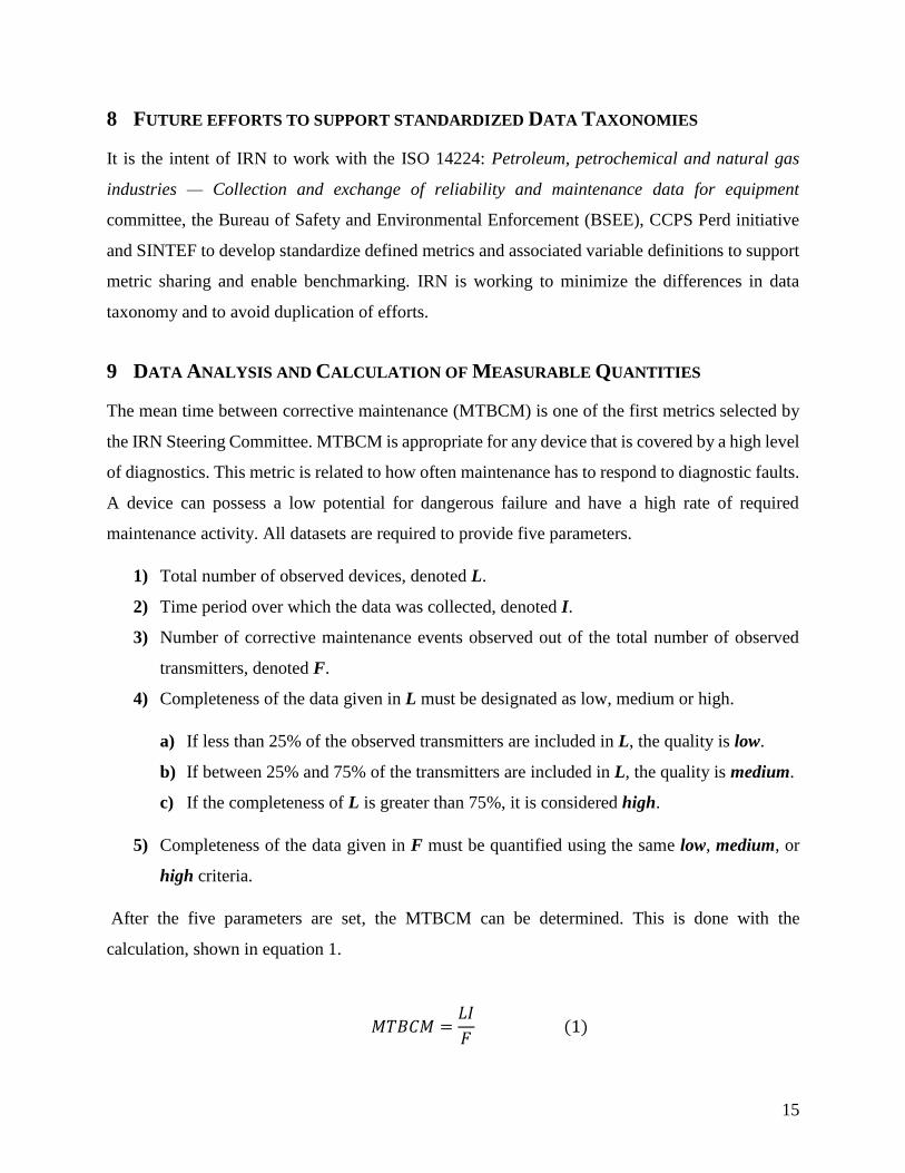
9 DATA ANALYSIS AND CALCULATION OF MEASURABLE QUANTITIES
The mean time between corrective maintenance (MTBCM) is one of the first metrics selected by
the IRN Steering Committee. MTBCM is appropriate for any device that is covered by a high level
of diagnostics. This metric is related to how often maintenance has to respond to diagnostic faults.
A device can possess a low potential for dangerous failure and have a high rate of required
maintenance activity. All datasets are required to provide five parameters.
1) Total number of observed devices, denoted L.
2) Time period over which the data was collected, denoted I.
3) Number of corrective maintenance events observed out of the total number of observed
transmitters, denoted F.
4) Completeness of the data given in L must be designated as low, medium or high.
a) If less than 25% of the observed transmitters are included in L, the quality is low.
b) If between 25% and 75% of the transmitters are included in L, the quality is medium.
c) If the completeness of L is greater than 75%, it is considered high.
5) Completeness of the data given in F must be quantified using the same low, medium, or
high criteria.
After the five parameters are set, the MTBCM can be determined. This is done with the
calculation, shown in equation 1.
𝑀𝑇𝐵𝐶𝑀 =𝐿𝐼
𝐹 (1)

16
Statistical Analysis: The initial step consisted in analyzing the normal distribution of the datasets
provided. As part of the analysis, both mean value and the sample standard deviation need to be
calculated applying the following equations.
𝑀𝑒𝑎𝑛 =∑ 𝑀𝑇𝐵𝐶𝑀𝑖
𝑁𝑖=1
𝑁 (2)
𝑠 = √∑𝑀𝑇𝐵𝐶𝑀𝑖 − 𝑀𝑒𝑎𝑛
𝑁 − 1 (3)
Here N is the total number of data points; and 𝑀𝑇𝐵𝐶𝑀𝑖 is the mean time between maintenance
for dataset 𝑖.
Once the mean and sample standard deviation are known, a Gaussian distribution curve is obtained
based on equation (4).
𝑓(𝑥) =1
𝑠
1𝑒−(𝑥−𝑀𝑒𝑎𝑛
𝑠)
2
√𝜋 (4)
Here, x represents mean time between maintenance (in years) and may vary between zero and
infinite.
The second step of the study consisted in plotting a boxplot graph to evaluate how the data was
distributed. To provide a better understanding of the distribution shape, the data was combined in
subsets (0-9 years, 10-19 years, 20-29 years etc.) and their frequency was further studied.
At the final stage, the Tukey-Kramer* method was applied via JMP Statistical Software to
determine whether the difference between each company’s MTBCM results were statistically
significant. In phase 1 of this work, the differences between each company are not statistically
significant at a 95% confidence level.
*Tukey-Kramer method is commonly used to find means that are significantly different from each other.

17
Appendix A – IRN Contact Information
IRN Foundation Board Member Angela Summers, President, SIS-TECH
[email protected] 713-829-0239
IRN Foundation Board Member Dr. Sam Mannan, MKOPSC Director
Top Management Valerie Green, MKOPSC Associate Director
[email protected] 979-845-6884
Assistant Alanna Scheinerman
Email contact [email protected]
IRN Website https://irn.tamu.edu
Qualtrics https://tamu.qualtrics.com/jfe/form/SV_1ZTLreptlzV1dHf

18
Appendix B Mutual Non-disclosure Agreement
THIS MUTUAL NON-DISCLOSURE AGREEMENT (“Agreement”) is entered into by and between the
Member(s) of the Texas A&M University System (“System”) hereinafter listed and the non-system Party
or Parties hereinafter listed, together the “Parties,” to assure the protection and preservation of confidential
information anticipated to be disclosed to each other for the purpose identified below:
1. PARTIES AND PRIMARY CONTACTS:
System Party
Party and Notice Contact: Individual(s) exchanging Confidential Information:
Member: Texas A&M Engineering Experiment Station Member: Texas A&M Engineering Experiment Station
Attn: Mark Andrews Attn: Sam Mannan
Address: 7607 Eastmark Drive, Contracts Office
College Station, TX 77840
Address: 3122 TAMU
College Station, TX 77843-3122
Phone: 979-458-7482 Phone: 979-862-3985
Email: [email protected],
Email: [email protected]
System Party includes the Texas A&M System Technology Commercialization (“TTC”).
According to System Policies 17.01.3 and 17.01.4, TTC is responsible for administering System
rights and obligations relating to technology transfer including evaluating commercial potential,
determining inventorship, obtaining necessary legal protection, and licensure. TTC also advises
creator(s) of intellectual property and System members on the process and best practices of
protecting and commercializing intellectual property. TTC may be called in as required to assist
with issues relating to this Agreement and is therefore included herein as a System Party.
Non-System Party
Party and Notice Contact: Individual(s) exchanging Confidential Information:
Name: Name:
Attn: Attn:
Address: Address:
Phone: Phone:
Email: Email:
2. PURPOSE AND SPECIFICS: In consideration for making confidential and/or proprietary trade and
business information (“Confidential Information”) available to the other Party, the Parties hereby agree to
the terms set out herein including the following summary set out for purposes of convenience:
Purpose:
Effective Date:
Duration: Two years from the Effective Date.
Confidentiality Term: Three years from the date of disclosure of Confidential Information

19
3. CONFIDENTIAL INFORMATION: Subject to the limitations set forth in Article 4, all non-public
information exchanged between the Parties shall be deemed to be Confidential Information. In order for
the Parties to appreciate when non-public information is being conveyed, to the reasonable extent possible,
information disclosed in tangible form shall be clearly identified at the time of disclosure as being
Confidential Information by an appropriate and conspicuous marking. Similarly, to the reasonable extent
possible, information disclosed in intangible form (e.g., oral or visual) shall be identified as being
Confidential Information at the time of disclosure, and shall be confirmed as such in writing to the
Receiving Party within thirty (30) days after such disclosure.
Confidential Information shall include as examples, without limitation:
All information of a Disclosing Party which has been maintained as confidential, including draft
publications, technical reports, research plans and results, processes, techniques, know-how,
biological materials, computer source code, diagrams, electronic files, financial information,
customer lists, trade secrets, invention disclosures, patent applications or test data;
all existing and future plans of the Disclosing Party, which have been maintained as confidential,
including plans relating to existing and planned products, research, development, engineering,
manufacturing, marketing, servicing, or financing;
all past, present and future business or commercial relationships of the Disclosing Party, which
have been maintained as confidential, including suppliers, service providers, clients, customers,
employees, or investors; or
information that has generally been considered and treated by the Disclosing Party as confidential
prior to the time of disclosure and is clearly identified as “Confidential” or “Proprietary” when
disclosed to the other Party.
4. EXCLUSIONS FROM CONFIDENTIAL INFORMATION: Confidential Information shall not be deemed to
include information that the Receiving Party can demonstrate by competent written proof:
is now, or hereafter becomes, publicly known or available through no act or failure to act on the
part of the Receiving Party;
was known by the Receiving Party at the time of receipt of such information as evidenced by its
records;
is hereafter furnished to the Receiving Party by a third party as a matter of right and without
violating any confidentiality obligation to the Disclosing Party; or
was independently developed by employees of the Receiving Party without use or knowledge of
the Confidential Information of the Disclosing Party.
5. USE OF CONFIDENTIAL INFORMATION: Each Party agrees that it will use the Confidential
Information of the other solely for the Purpose and for no other purpose whatsoever. In particular, the
Receiving Party shall not file any patent application containing any claim to subject matter derived in
whole or in part from the Disclosing Party’s Confidential Information. The Confidential Information,
including any documents, drawings, sketches, designs, materials or samples supplied hereunder, shall
remain the property of the Party disclosing the same and no rights or licenses are granted to the other
Party in the same, whether patented or not, except the limited right to use the Confidential Information
as set forth above.
6. CONFIDENTIAL OBLIGATIONS: The Parties agree to exert reasonable efforts to maintain each other’s
Confidential Information in confidence and to take all necessary and reasonable precautions to prevent
its unauthorized disclosure and to ensure it does not fall into the public domain or the possession of
unauthorized third parties. Each Party shall restrict access to the Confidential Information of the other
Party to those officers, employees, consultants, agents, and students (in the case of Member) of the
Receiving Party having a need to know the Confidential Information to fulfill the Purpose, provided

20
that each Party shall ensure that any individual having access to the Confidential Information is made
expressly aware of the obligation of confidence according to the terms hereof prior to gaining access
to the Confidential Information. To the extent that a Party perceives a need for disclosure of the
Confidential Information it receives from the other Party to any third party, such third party shall be
prospectively identified, and written permission to disclose shall be obtained. A written non-disclosure
agreement shall be obtained from the third party contractor and a copy shall be promptly provided to
the Party whose Confidential Information is being disclosed.
7. REQUIRED DISCLOSURE: If a Receiving Party is legally required by court order, law, or other
governmental regulation or authority to disclose certain Confidential Information received from a
Disclosing Party, such disclosure may be made only after giving written notice to the Disclosing Party
and providing a reasonable opportunity for pursuit of appropriate process to prevent or limit such
disclosure. In any event, required disclosure shall be limited to only that portion of the Confidential
Information which is legally required to be disclosed. The Receiving Party is not however, required
to pursue any claim, defense, cause of action, or legal process or proceeding on the Disclosing Party’s
behalf.
8. RETURN OF DOCUMENTS: It is understood that the Confidential Information disclosed by each
Party shall remain the property of the Disclosing Party. All material or documents furnished by
the Disclosing Party, including all copies, shall upon request of the Disclosing Party, or in any
event at the termination of this Agreement, be promptly returned to the Disclosing Party or
destroyed, except that the Receiving Party may securely retain one copy in its files solely for
record purposes of its obligations under this Agreement.
9. PUBLICITY: The Parties agree that the name of the Member or of The Texas A&M University System
will not be used in any advertising, sales promotion, or other publicity matter without the prior written
approval of the Member and/or The Texas A&M University System, respectively.
10. INJUNCTION: The Parties agree that, in the event of breach or threatened breach or intended breach
of the Agreement, each Party, in addition to any other rights and remedies available to it at law or in
equity, may seek injunctive or equitable relief.
11. DISCLAIMER OF WARRANTIES: The Parties make no warranty whatsoever regarding the
Confidential Information. Neither Party makes any representations or warranties, written or
oral, express or implied, as to Confidential Information, including without limitation, any
warranty of merchantability or of fitness for a particular purpose.
12. TERM: This Agreement shall continue in full force and effect for the duration set out in Article
2. This Agreement may be terminated by either Party at any time upon thirty (30) days written
notice to the other Party. The confidentiality and non-use obligations of each Party with respect
to Confidential Information disclosed under this Agreement shall remain in effect for the
Confidentiality Term set out in Article 2 and will survive the termination of this Agreement.
13. NOTIFICATIONS: The Parties shall promptly advise each other in writing of any known
misappropriation or misuse by any person of Confidential Information and shall take prompt
and effective steps to prevent a recurrence of such misappropriation or misuse. Any notices
required or permitted hereunder shall be given to the appropriate Party at the address specified
in Article 1 or at such other address as the Party shall specify in writing. Such notice shall be
deemed given upon the personal delivery, or three (3) days after the date of mailing when sent
by certified or registered mail, postage prepaid.

21
14. GOVERNING LAW: This Agreement shall be interpreted and enforced by the laws of the State of
Texas. Venue for any claim arising under this Agreement shall be as provided by Texas State
law.
15. MISCELLANEOUS:
State Agency: Member is an agency of the State of Texas and nothing in this Agreement waives
or relinquishes Member’s right to claim any exemptions, privileges, and immunities as may be
provided by law.
No Future Commitments: No agency, partnership, joint venture, or exclusive relationship is created
by this Agreement and each Party is free to pursue other opportunities such as those contemplated
under the Agreement. No further obligations are created under this Agreement except those stated
herein.
Export Control: The Parties agree to comply with U.S. export control regulations. If a Party desires
to disclose to another Party hereto, whether directly or indirectly, any information, technology or
data that is identified on any U.S. export control list, including the Commerce Control List of 15
C.F.R. Part 774 and the U.S. Munitions List of 22 C.F.R. 121, the Disclosing Party will advise the
Receiving Party at the time of disclosure and the Receiving Party will advise the Disclosing Party
if it desires to take receipt of the export-controlled materials. No information subject to export
controls may be provided to another party hereto without the written consent of the Receiving
Party’s Notice Contact identified in Article 1.
Assignment: The Parties’ rights and obligations under this Agreement will bind and inure to the
benefit of their respective successors, heirs, executors and administrators and permitted assigns.
Neither Party shall assign or delegate its obligations under this Agreement, in whole or in part,
without the prior written consent of the other Party.
Severability: A failure to enforce any provision of this Agreement shall not constitute a waiver of
any term hereof. The invalidity or unenforceability of any provision of this Agreement shall not
affect the remaining provisions or portions thereof.
Entire Agreement: This Agreement sets forth the entire agreement of the Parties relating to the
subject matter hereof and supersedes all prior and contemporaneous agreements and understandings
relating to its subject matter. This Agreement may not be amended or superseded except by a
written agreement signed by an authorized representative of each Party.
Authority and Counterparts: The person executing this Agreement on behalf of a Party warrants
that such person has full authorization to execute this Agreement. Execution counterparts to this
Agreement will be deemed to constitute one and the same instrument.
IN WITNESS WHEREOF, the Parties have executed this Agreement on the date written below:
Texas A&M Engineering Experiment Station
Signed: ____________________________
Name: Mark Andrews
Title: TEES Contracting Officer
Date: ____________________________

22
Signed: ____________________________
Name: ____________________________
Title: ____________________________
Date: _____________________________

23
Appendix C - Project Charter
Section 1: To be completed by MKOPSC
Project Charter # Approval Date
Target Start Date Target Completion Date
Section 2: To be completed by Project Submitter
Project Title
Project Team Leader
Project Description:
Problem and goal statement
(project’s purpose)
Business Cases: Justification for proposed
scope.
Equipment Taxonomy:
Document the equipment
taxonomy per MKOPSC IRN
Defined Equipment
Taxonomy.
Project Duration
Estimate the timing for the
Definition, Pilot and Study
Phases.
Target Date Actual Date
Definition Phase
Pilot Phase
Study Phase
Measurement(s)
Project Measurement(s)
What measurements are
targeted
For this project. Describe the
Measurement using approved
terms and definitions from
MKOPSC IRN Defined
Metrics Document
Measurement Measurement Description
Measurement 1
Measurement 2
Future Measurement(s)
Describe future
measurements that may be
considered as part of the
multi-generational plan.
Team members
Names and roles of team
Measurement 3
Future Measurement
Taxonomy Group
Quality Assurance Group
Members? Outreach Group
Mary Kay O’Connor
Process Safety Center
24
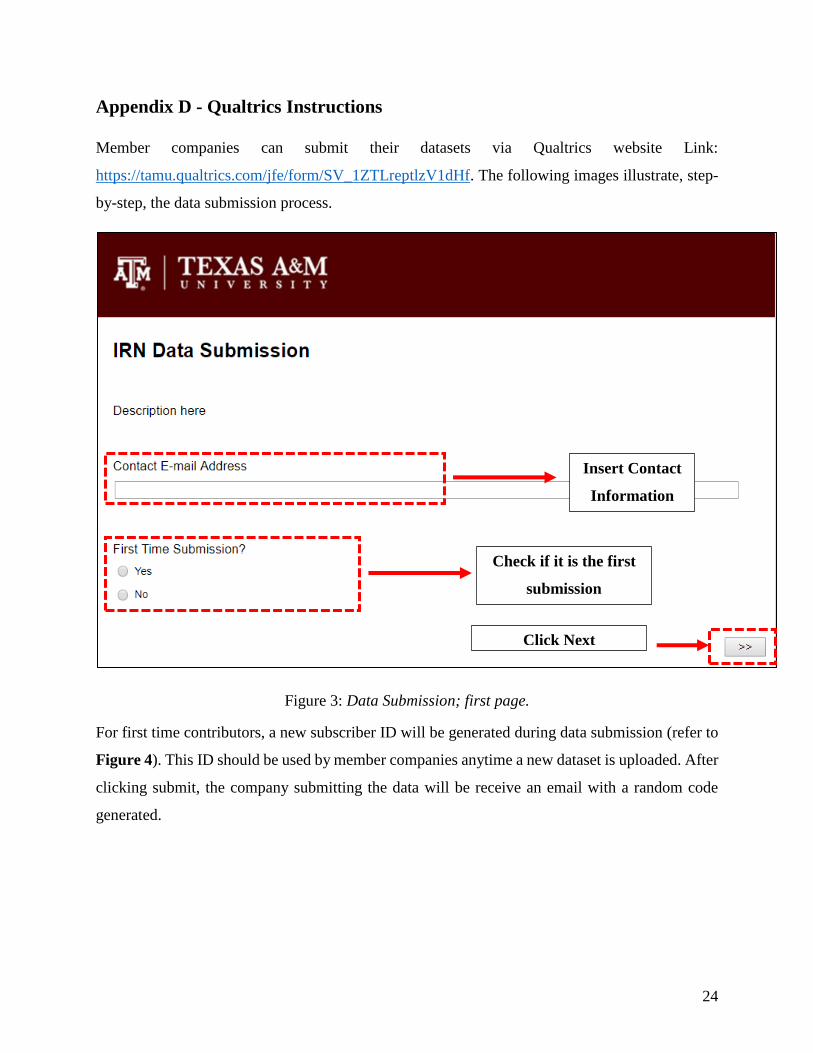
Appendix D - Qualtrics Instructions
Member companies can submit their datasets via Qualtrics website Link:
https://tamu.qualtrics.com/jfe/form/SV_1ZTLreptlzV1dHf. The following images illustrate, step-
by-step, the data submission process.
Figure 3: Data Submission; first page.
For first time contributors, a new subscriber ID will be generated during data submission (refer to
Figure 4). This ID should be used by member companies anytime a new dataset is uploaded. After
clicking submit, the company submitting the data will be receive an email with a random code
generated.
Check if it is the first
submission
Insert Contact
Information
Click Next
25
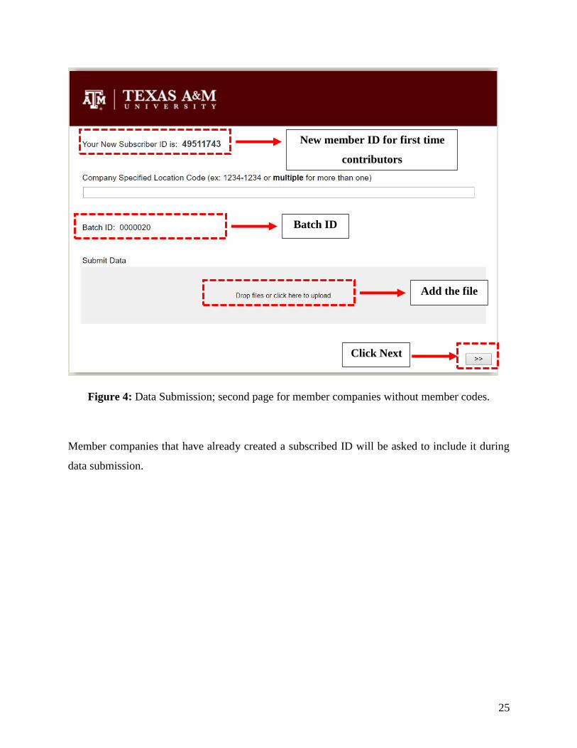
Figure 4: Data Submission; second page for member companies without member codes.
Member companies that have already created a subscribed ID will be asked to include it during
data submission.
New member ID for first time
contributors
Batch ID
Add the file
Click Next
26
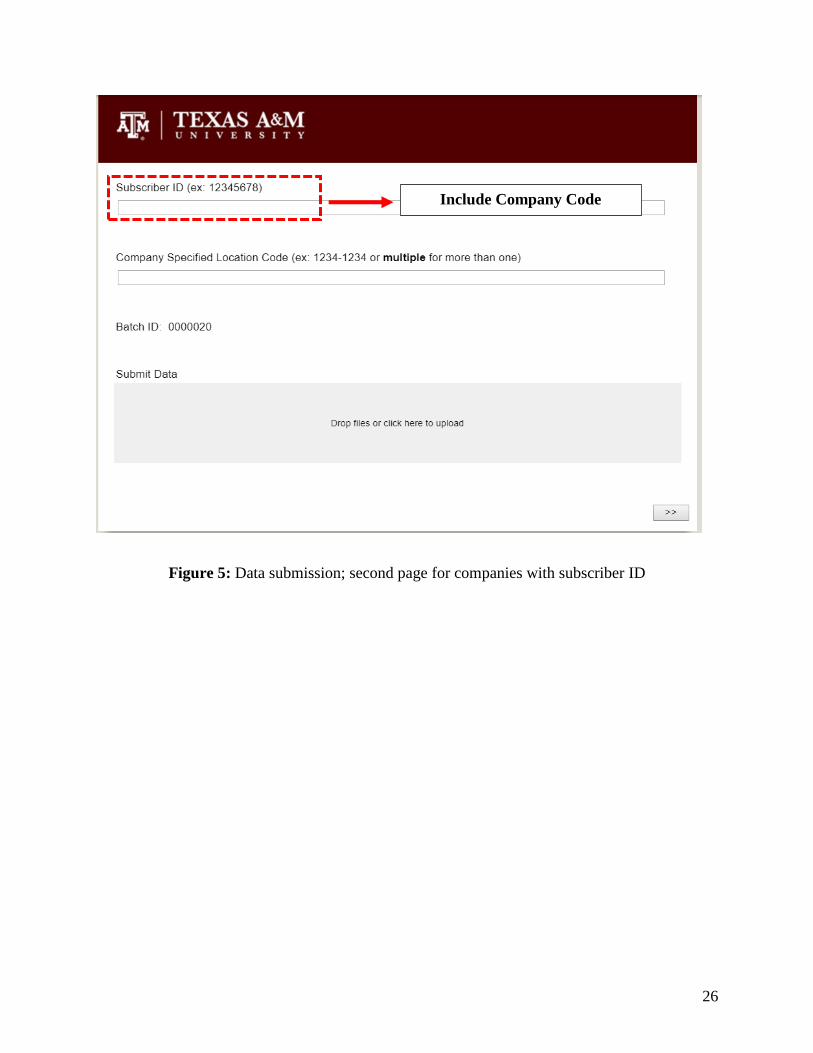
Figure 5: Data submission; second page for companies with subscriber ID
Include Company Code

27
Appendix E - Algorithm for Analysis
Table 1. Time Related Failure Rates - Complete Loss of Function.
Failure
Mode Symbol Unit Algorithm to do analysis
Equipment
rupture
EQPR
unit Time
Failures
n
1iCTi
NfEQPR
EQPR (Calendar Time Basis)
n
1iOTi
NfEQPR
EQPR (Operating Time Basis)
Must sum failures from the Loss of containment tab
Fail to
open
FTO unit Time
Failures
n
1iCTi
NfFTO
FTO (Calendar Time Basis)
n
1iOTi
NfFTO
FTO (Operating Time Basis)
Must sum failures from the Inspection, Demand and Proof Test
Tabs
Spuriously
opens
SPO unit Time
Failures
n
1iCTi
NfSPO
SPO (Calendar Time Basis)
n
1iOTi
NfSPO
SPO (Operating Time Basis)
Must sum failures from the Demand and Proof Test Tabs
28
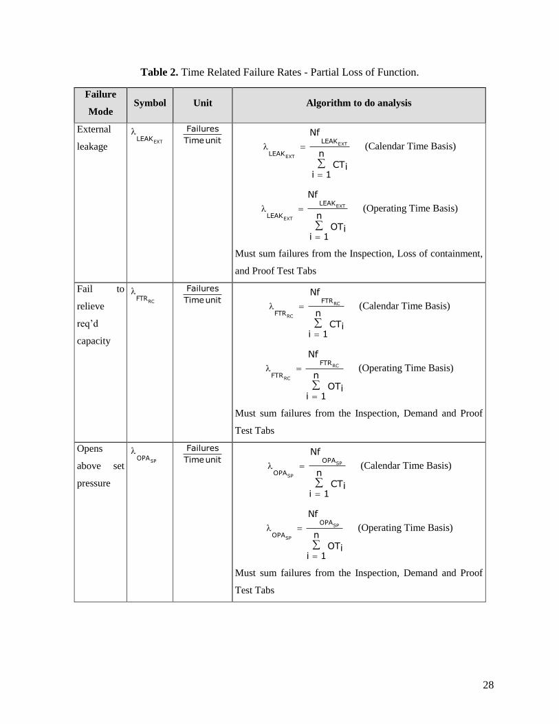
Table 2. Time Related Failure Rates - Partial Loss of Function.
Failure
Mode Symbol Unit Algorithm to do analysis
External
leakage EXT
LEAK
unit Time
Failures
n
1iCTi
NfEXT
EXT
LEAK
LEAK (Calendar Time Basis)
n
1iOTi
NfEXT
EXT
LEAK
LEAK (Operating Time Basis)
Must sum failures from the Inspection, Loss of containment,
and Proof Test Tabs
Fail to
relieve
req’d
capacity
RCFTR
unit Time
Failures
n
1iCTi
NfRC
RC
FTR
FTR (Calendar Time Basis)
n
1iOTi
NfRC
RC
FTR
FTR (Operating Time Basis)
Must sum failures from the Inspection, Demand and Proof
Test Tabs
Opens
above set
pressure
SPOPA
unit Time
Failures
n
1iCTi
NfSP
SP
OPA
OPA (Calendar Time Basis)
n
1iOTi
NfSP
SP
OPA
OPA (Operating Time Basis)
Must sum failures from the Inspection, Demand and Proof
Test Tabs

29
Failure
Mode Symbol Unit Algorithm to do analysis
Seat
leakage SEAT
LEAK
unit Time
Failures
n
1iCTi
NfSEAT
SEAT
LEAK
LEAK (Calendar Time Basis)
n
1iOTi
NfSEAT
SEAT
LEAK
LEAK (Operating Time Basis)
Must sum failures from the Inspection, Demand and Proof
Test Tabs
Table 3. Time Related Failure Rates - Partial Loss of Function.
Failure
Mode Symbol Unit Algorithm to do analysis
Fail to open
FTOPFD decimal
FTO
FTOFTO
D
NfPFD
Must sum failures from the Demand and Proof Test Tabs
Fail to
reseat
FTRSTPFD decimal
FTRST
FTRSTFTRST
D
NfPFD
Must sum failures from the Demand and Proof Test Tabs
Table 4. Demand Related Probabilities of Failure – Partial Loss of Function.
Failure
Mode Symbol Unit Algorithm to do analysis
Fail to
relieve req’d
capacity
RCFTRPFD
decimal
RC
RC
RC
FTR
FTR
FTRD
NfPFD
Must sum failures from the Demand and Proof Test Tabs
Fails to
completely
reseat
FTCRPFD decimal
FTCR
FTCRFTCR
D
NfPFD
Must sum failures from the Demand and Proof Test Tabs

30
Failure
Mode Symbol Unit Algorithm to do analysis
Opens above
set pressure
SPOPAPFD
decimal
SP
SP
SP
OPA
OPA
OPAD
NfPFD
Must sum failures from the Demand and Proof Test Tabs
Opens below
set pressure
SPOPBPFD
decimal
SP
SP
SP
OPB
OPB
OPBD
NfPFD
Must sum failures from the Demand and Proof Test Tabs
Table 5. Mean Time to Restore Calculations.
Indicator Symbol Unit Algorithm to do analysis
Mean Time
to Restore,
failures
MTTRf Time
unit
n
n
1iTTRf
MTTR f
Must include time to restore data from the following applicable event tables:
Maintenance/Repair
Table 6. Availability Calculations.
Indicator Symbol Unit Algorithm to do analysis
Intrinsic
Availability
Ai Decimal
n
1i MTTRMTTF
MTTFA
fi
n
1i n
TTFMTTF
n
1i n
TTRMTTR
ff
Data from applicable event tables. Only include shutdowns due to forced
maintenance