Instrument for measuring -...
39
1 Yusaku Fujii Yusaku Fujii Gunma University Gunma University Instrument for measuring Instrument for measuring astronaut body mass astronaut body mass 84th Annual AsMA Scientific Meeting Chicago, USA - May 12-16 2013
Transcript of Instrument for measuring -...
1
Yusaku Fujii Yusaku Fujii Gunma UniversityGunma University
Instrument for measuringInstrument for measuring
astronaut body mass astronaut body mass
84th Annual AsMA Scientific Meeting
Chicago, USA - May 12-16 2013

Disclosure Information84th Annual AsMA Scientific Meeting
Yusaku FUJII
I have no financial relationships to disclose.
I will not discuss off-label use and/or investigational use in my presentation
3
4
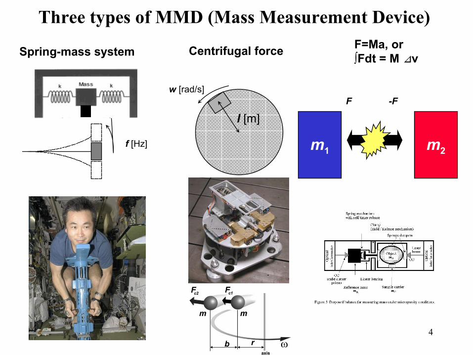
Three types of MMD (Mass Measurement Device)
f [Hz]
l [m]
w [rad/s]
m1 m2
F -F
Spring-mass system Centrifugal forceF=Ma, or ∫Fdt = M v⊿
5
Methods proposed by Fujii Laboratory
SMMD: Small Mass Measurement Device
BMMD: Body Mass Measurement Device
6
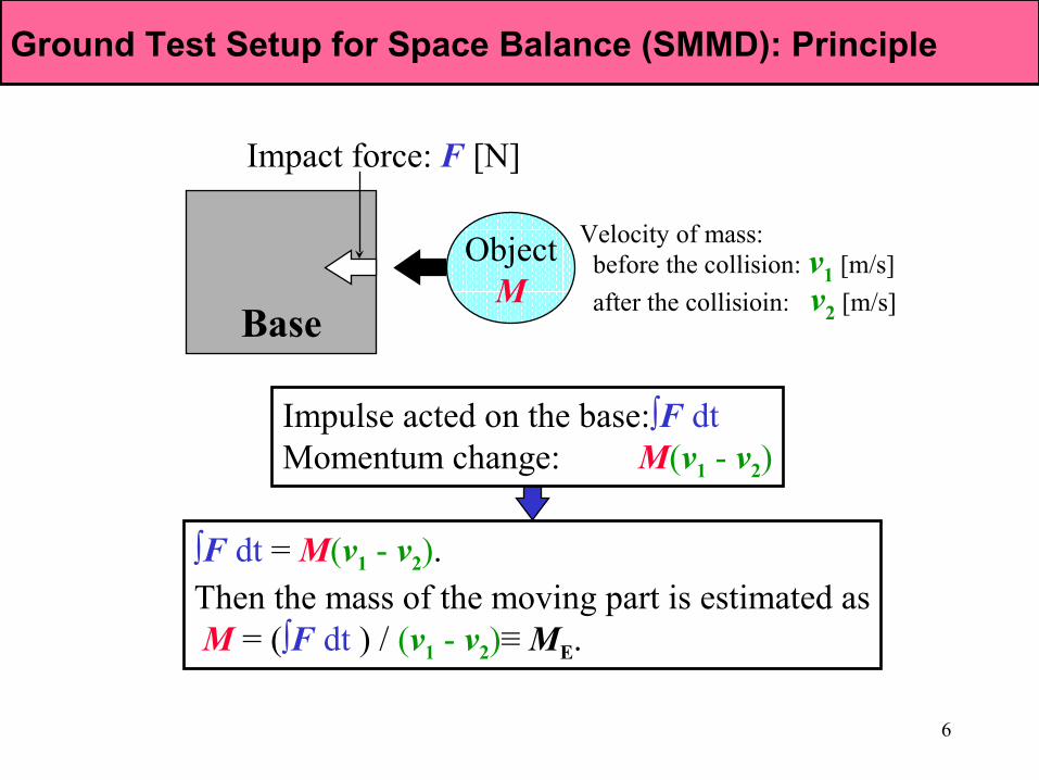
Ground Test Setup for Space BalanceGround Test Setup for Space BalanceGround Test Setup for Space Balance (SMMD): Principle
∫F dt = M(v1 - v2). Then the mass of the moving part is estimated as M = (∫F dt ) / (v1 - v2)≡ ME.
ObjectM
Base
Impact force: F [N]
Velocity of mass: before the collision: v1 [m/s]
after the collisioin: v2 [m/s]
Impulse acted on the base:∫F dt Momentum change: M(v1 - v2)
7
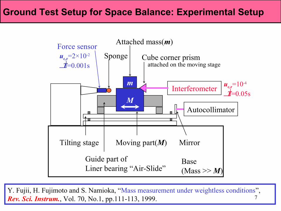
Ground Test Setup for Space BalanceGround Test Setup for Space BalanceGround Test Setup for Space Balance: Experimental Setup
M
m
Tilting stage Mirror
Autocollimator
Interferometer
Force sensorSponge Cube corner prism
attached on the moving stage
Moving part(M)
Guide part ofLiner bearing “Air-Slide”
Attached mass(m)
Base (Mass >> M)
uc,r=10-4
T=0.05s
uc,r=2×10⁻²
T=0.001s
Y. Fujii, H. Fujimoto and S. Namioka, “Mass measurement under weightless conditions”, Rev. Sci. Instrum., Vol. 70, No.1, pp.111-113, 1999.
8
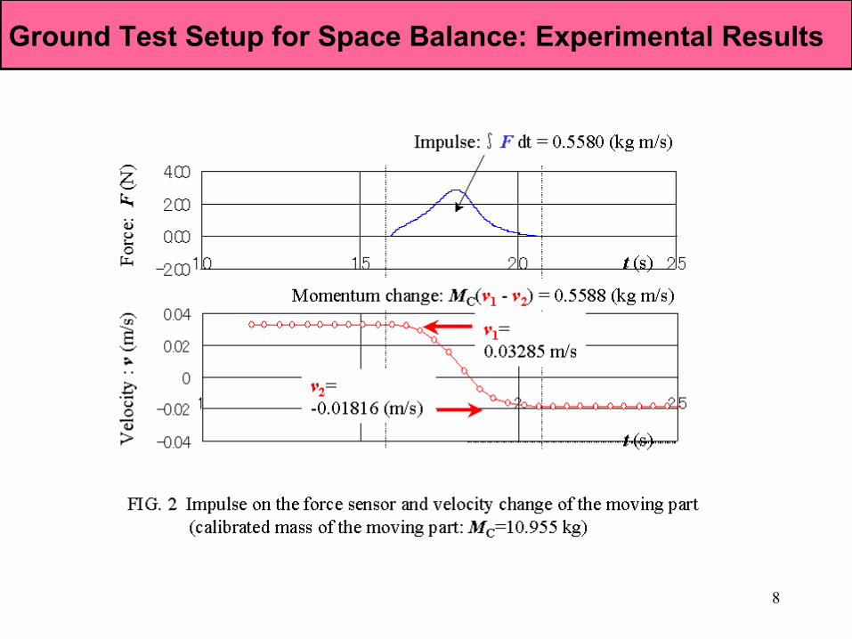
Ground Test Setup for Space BalanceGround Test Setup for Space BalanceGround Test Setup for Space Balance: Experimental Results
9
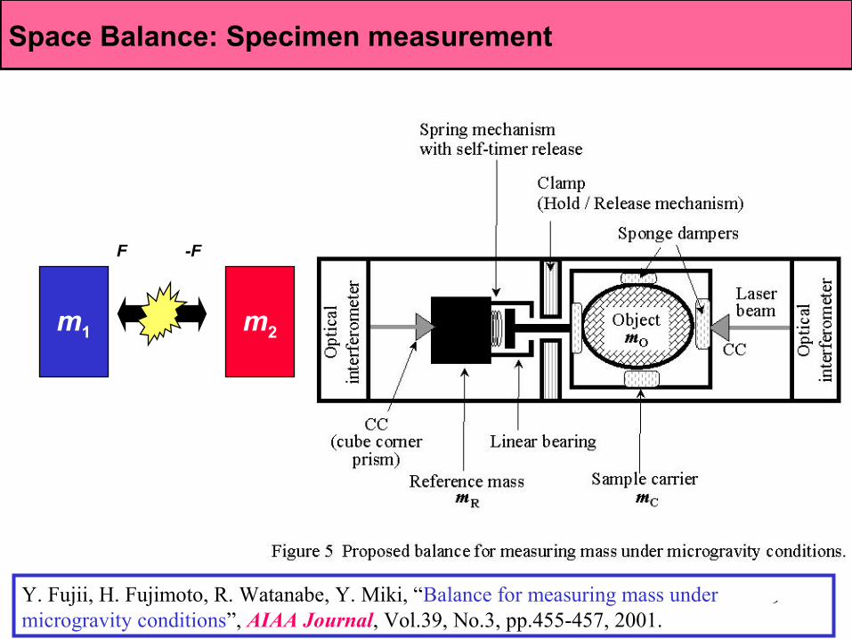
Ground Test Setup for Space BalanceGround Test Setup for Space BalanceSpace Balance: Specimen measurement
Y. Fujii, H. Fujimoto, R. Watanabe, Y. Miki, “Balance for measuring mass under microgravity conditions”, AIAA Journal, Vol.39, No.3, pp.455-457, 2001.
m1 m2
F -F
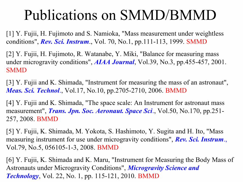
Publications on SMMD/BMMD[1] Y. Fujii, H. Fujimoto and S. Namioka, "Mass measurement under weightless conditions", Rev. Sci. Instrum., Vol. 70, No.1, pp.111-113, 1999. SMMD
[2] Y. Fujii, H. Fujimoto, R. Watanabe, Y. Miki, "Balance for measuring mass under microgravity conditions", AIAA Journal, Vol.39, No.3, pp.455-457, 2001. SMMD
[3] Y. Fujii and K. Shimada, "Instrument for measuring the mass of an astronaut", Meas. Sci. Technol., Vol.17, No.10, pp.2705-2710, 2006. BMMD
[4] Y. Fujii and K. Shimada, "The space scale: An Instrument for astronaut mass measurement", Trans. Jpn. Soc. Aeronaut. Space Sci., Vol.50, No.170, pp.251-257, 2008. BMMD
[5] Y. Fujii, K. Shimada, M. Yokota, S. Hashimoto, Y. Sugita and H. Ito, "Mass measuring instrument for use under microgravity conditions", Rev. Sci. Instrum., Vol.79, No.5, 056105-1-3, 2008. BMMD
[6] Y. Fujii, K. Shimada and K. Maru, "Instrument for Measuring the Body Mass of Astronauts under Microgravity Conditions", Microgravity Science and Technology, Vol. 22, No. 1, pp. 115-121, 2010. BMMD

Russian BMMDSpring-mass system
Movement of the body is observed.Body is not rigid during the measurement.
GC
Measurementpoint

Skylab BMMD
Rigid Object(0-100 kg)RMS 0.02kg!(0.02%)
Spring-mass system
13
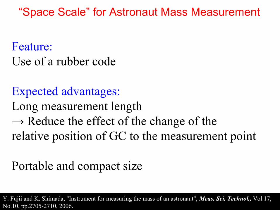
“Space Scale” for Astronaut Mass Measurement
Y. Fujii and K. Shimada, "Instrument for measuring the mass of an astronaut", Meas. Sci. Technol., Vol.17, No.10, pp.2705-2710, 2006.
Feature: Use of a rubber code
Expected advantages:Long measurement length→ Reduce the effect of the change of the relative position of GC to the measurement point
Portable and compact size
14
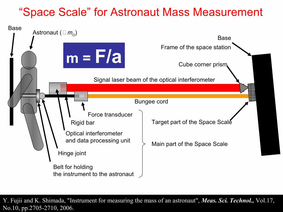
“Space Scale” for Astronaut Mass Measurement
Astronaut ( mO) Base
Frame of the space station
Belt for holding the instrument to the astronaut
Base
Bungee cord
Force transducerRigid bar
Hinge joint
Optical interferometer and data processing unit
Signal laser beam of the optical interferometer
Cube corner prism
Main part of the Space Scale
Target part of the Space Scale
m = F/a
Y. Fujii and K. Shimada, "Instrument for measuring the mass of an astronaut", Meas. Sci. Technol., Vol.17, No.10, pp.2705-2710, 2006.
15
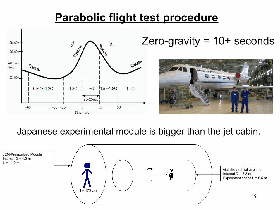
Flight experiment procedureParabolic flight test procedure
Gulfstream II jet parabola profile
JEM-Pressurized ModuleInternal D = 4.2 mL = 11.2 m
Gulfstream II jet airplaneInternal D = 2.2 mExperiment space L = 6.5 m
H = 175 cm
Japanese experimental module is bigger than the jet cabin.
Zero-gravity = 10+ seconds
16
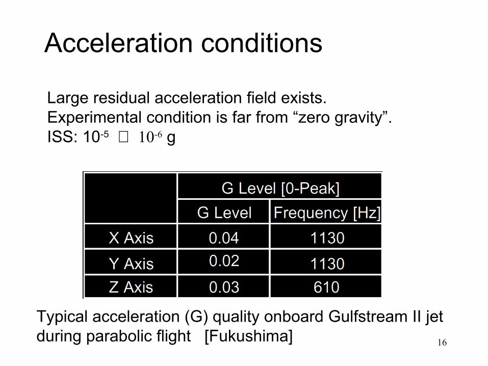
Acceleration field
Typical acceleration (G) quality onboard Gulfstream II jet during parabolic flight [Fukushima]
Large residual acceleration field exists.Experimental condition is far from “zero gravity”.ISS: 10-5 ~ 10-6 g
Acceleration conditions
17
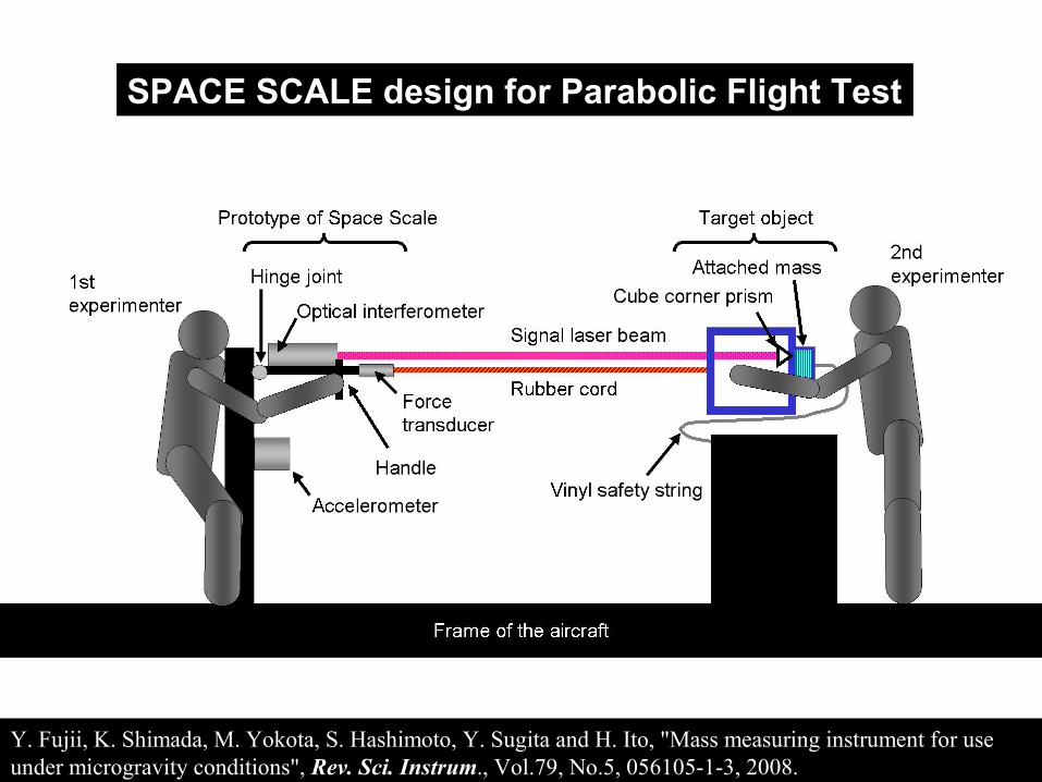
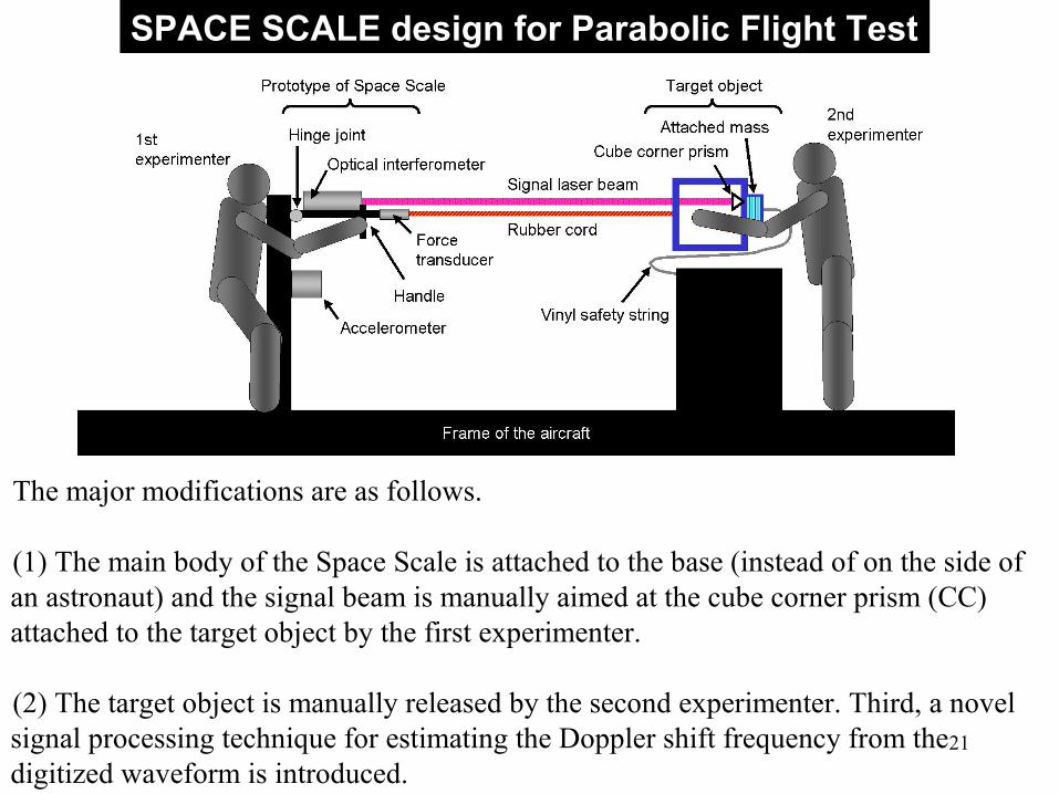
SPACE SCALE design for Parabolic Flight Test
Y. Fujii, K. Shimada, M. Yokota, S. Hashimoto, Y. Sugita and H. Ito, "Mass measuring instrument for use under microgravity conditions", Rev. Sci. Instrum., Vol.79, No.5, 056105-1-3, 2008.
18
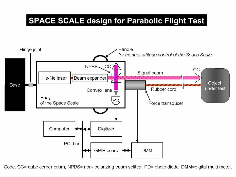
SPACE SCALE design for Parabolic Flight Test
19
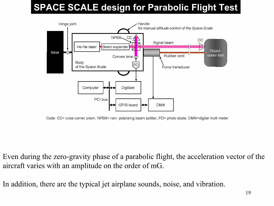
SPACE SCALE design for Parabolic Flight Test
Even during the zero-gravity phase of a parabolic flight, the acceleration vector of the aircraft varies with an amplitude on the order of mG.
In addition, there are the typical jet airplane sounds, noise, and vibration.

20
SPACE SCALE design for Parabolic Flight Test
In order to make the prototype work properly on the business jet, some modifications were made to the original design:
(3) Y. Fujii and K. Shimada, “Instrument for measuring the mass of an astronaut”, Meas. Sci. Technol., Vol.17, No.10, pp.2705-2710, 2006.(4) Y. Fujii and K. Shimada, “The space scale: An Instrument for astronaut mass measurement”, T. Jpn. Soc. Aeronaut. Space Sci., Vol. 50, No. 170, pp.251-257, 2007.
21
SPACE SCALE design for Parabolic Flight Test
The major modifications are as follows.
(1) The main body of the Space Scale is attached to the base (instead of on the side of an astronaut) and the signal beam is manually aimed at the cube corner prism (CC) attached to the target object by the first experimenter.
(2) The target object is manually released by the second experimenter. Third, a novel signal processing technique for estimating the Doppler shift frequency from the digitized waveform is introduced.
22
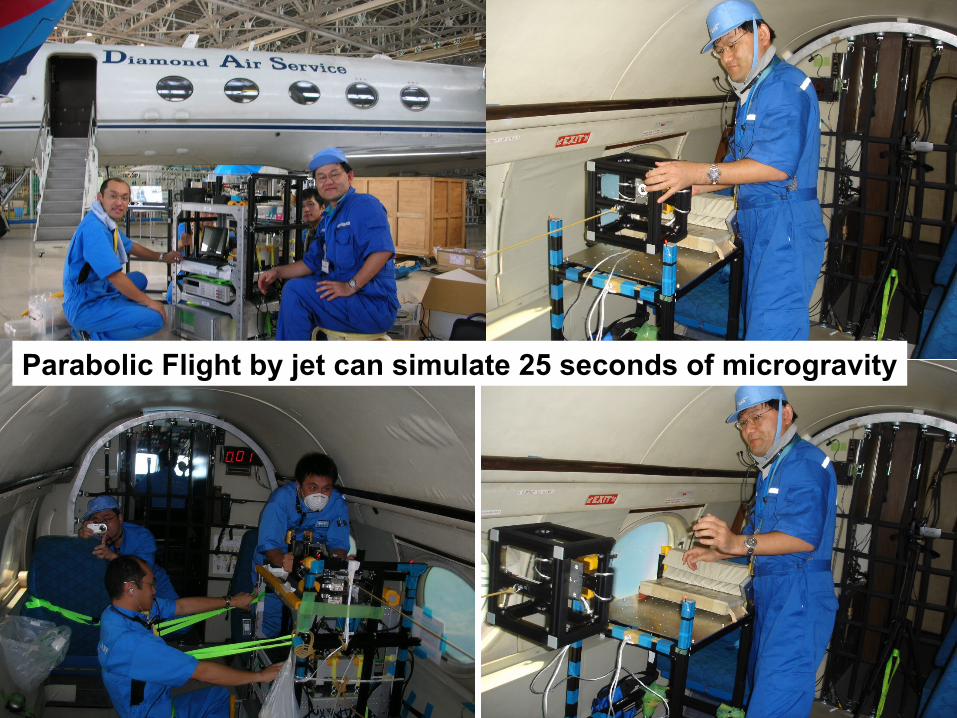
Parabolic Flight by jet can simulate 25 seconds of microgravity

23
24
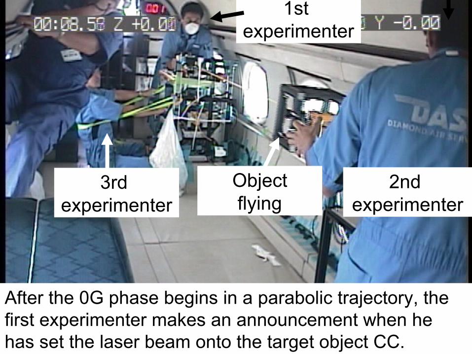
1st experimenter
2nd experimenter
After the 0G phase begins in a parabolic trajectory, the first experimenter makes an announcement when he has set the laser beam onto the target object CC.
Objectflying
3rd experimenter
25
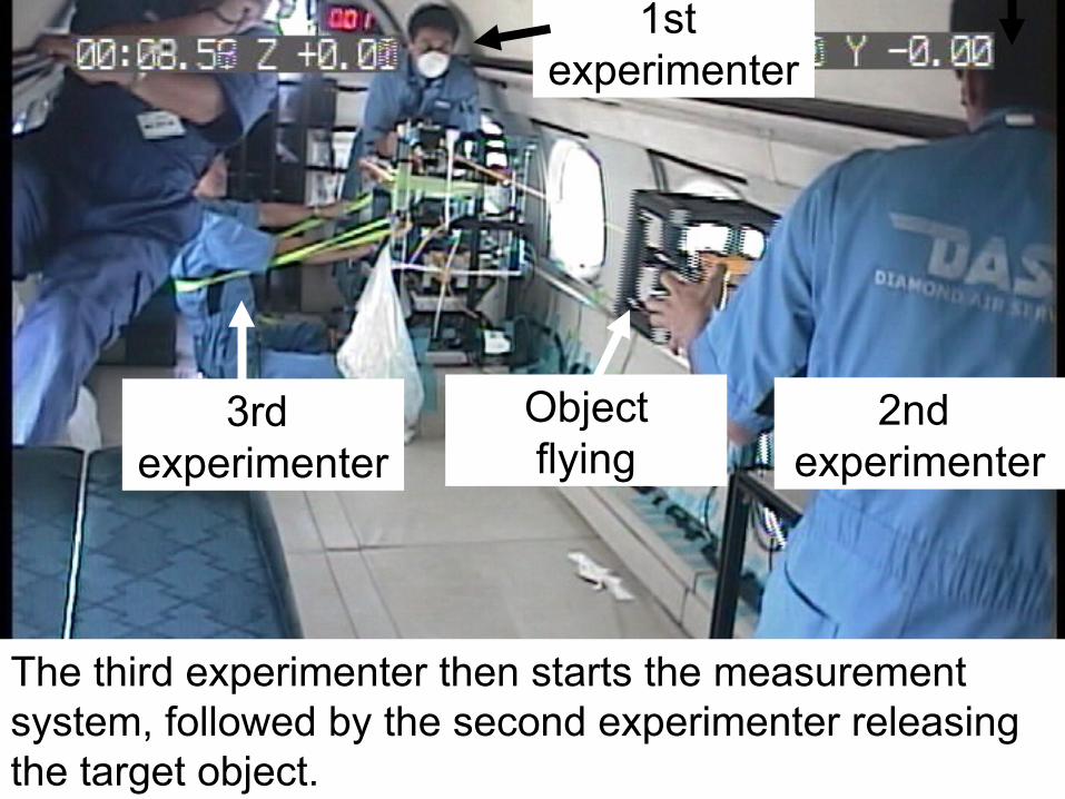
1st experimenter
2nd experimenter
The third experimenter then starts the measurement system, followed by the second experimenter releasing the target object.
Objectflying
3rd experimenter
26
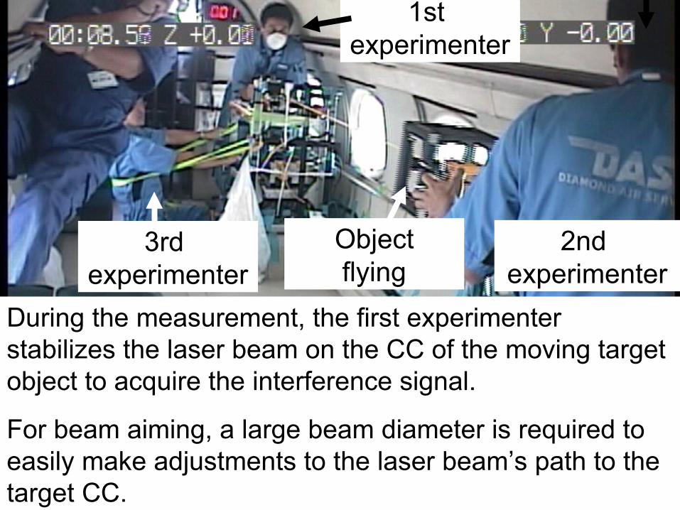
1st experimenter
2nd experimenter
During the measurement, the first experimenter stabilizes the laser beam on the CC of the moving target object to acquire the interference signal.
For beam aiming, a large beam diameter is required to easily make adjustments to the laser beam’s path to the target CC.
Objectflying
3rd experimenter
27
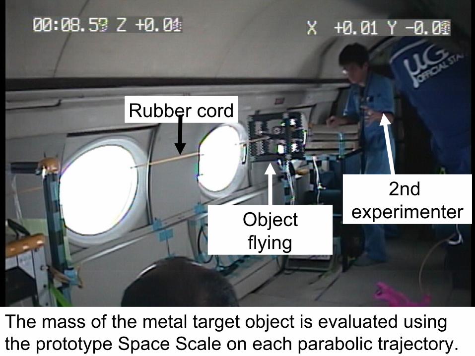
Rubber cord
Objectflying
2nd experimenter
The mass of the metal target object is evaluated using the prototype Space Scale on each parabolic trajectory.
28
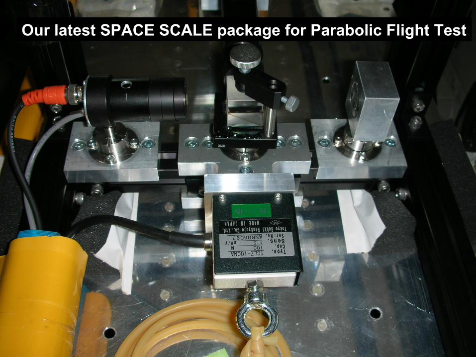
Our latest SPACE SCALE package for Parabolic Flight Test
29
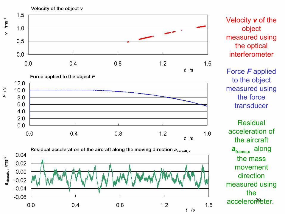
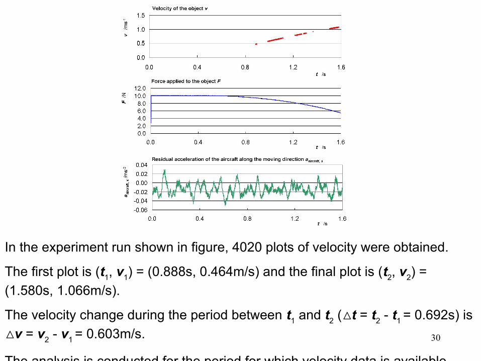
Velocity v of the object
measured using the optical
interferometer
Force F applied to the object
measured using the force
transducer
Residual acceleration of
the aircraft aframe,x along
the mass movement direction
measured using the
accelerometer.
30
In the experiment run shown in figure, 4020 plots of velocity were obtained.
The first plot is (t1, v1) = (0.888s, 0.464m/s) and the final plot is (t2, v2) =
(1.580s, 1.066m/s).
The velocity change during the period between t1 and t2 (△t = t2 - t1 = 0.692s) is
△v = v2 - v1 = 0.603m/s.
The analysis is conducted for the period for which velocity data is available.
31
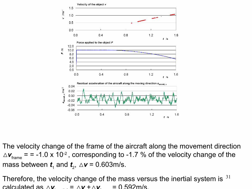
The velocity change of the frame of the aircraft along the movement direction △vframe = = -1.0 x 10⁻² , corresponding to -1.7 % of the velocity change of the
mass between t1 and t2, △v = 0.603m/s.
Therefore, the velocity change of the mass versus the inertial system is calculated as △vinertial = △v +△vframe = 0.592m/s.
32
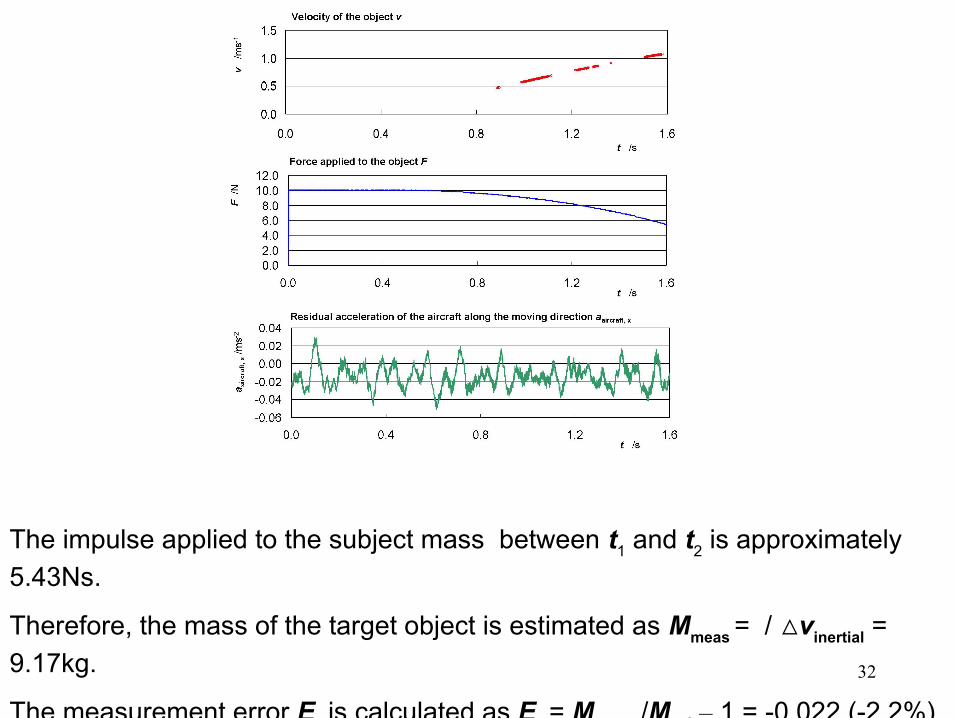
The impulse applied to the subject mass between t1 and t2 is approximately
5.43Ns.
Therefore, the mass of the target object is estimated as Mmeas = / △vinertial =
9.17kg.
The measurement error Er is calculated as Er = Mmeas /Mcal – 1 = -0.022 (-2.2%).
33
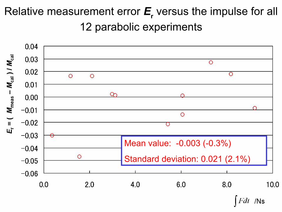
Relative measurement error Er versus the impulse for all
12 parabolic experiments
Mean value: -0.003 (-0.3%)
Standard deviation: 0.021 (2.1%)
34
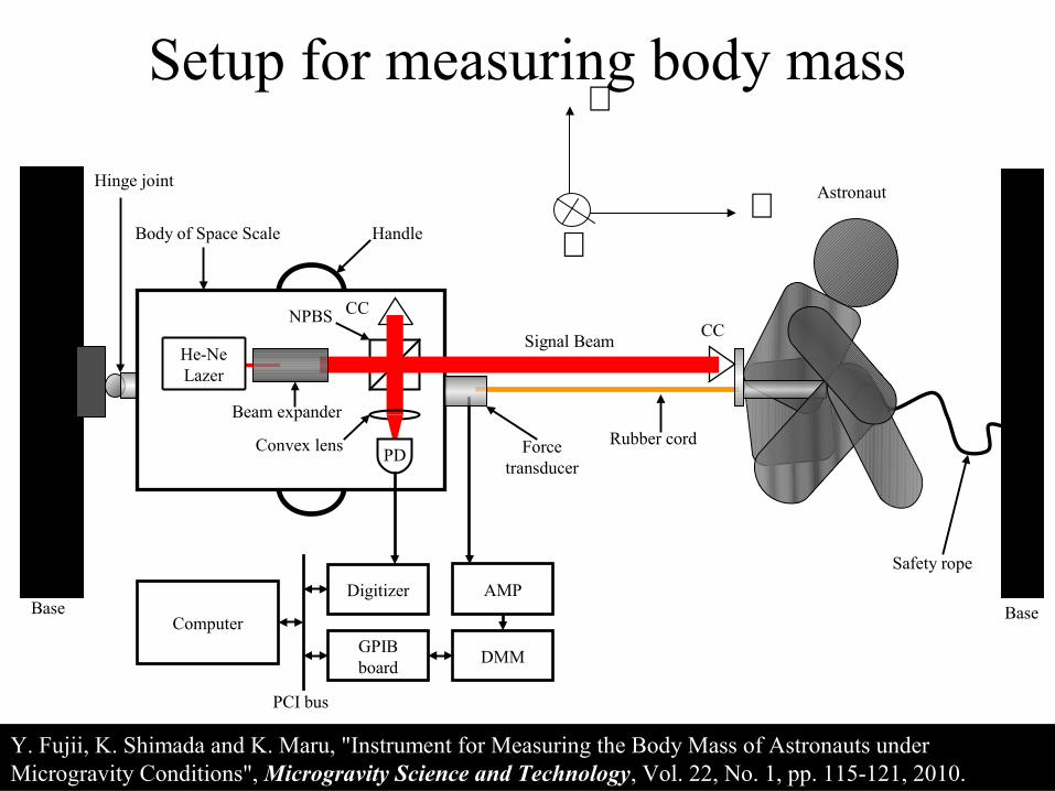
Setup for measuring body mass
BaseBase
CC
Rubber cordForce transducer
Hinge joint
Safety rope
Astronaut
He-Ne Lazer
PD
Body of Space Scale Handle
CCNPBS
Convex lens
Beam expander
Signal Beam
Computer
Digitizer
GPIB board
DMM
PCI bus
AMP
X
Y
Z
Y. Fujii, K. Shimada and K. Maru, "Instrument for Measuring the Body Mass of Astronauts under Microgravity Conditions", Microgravity Science and Technology, Vol. 22, No. 1, pp. 115-121, 2010.

35
Measurement of body mass
Body mass :M=93.3 [kg
2rd Experimenter
Subject
1st Experimenter
3rd Experimenter
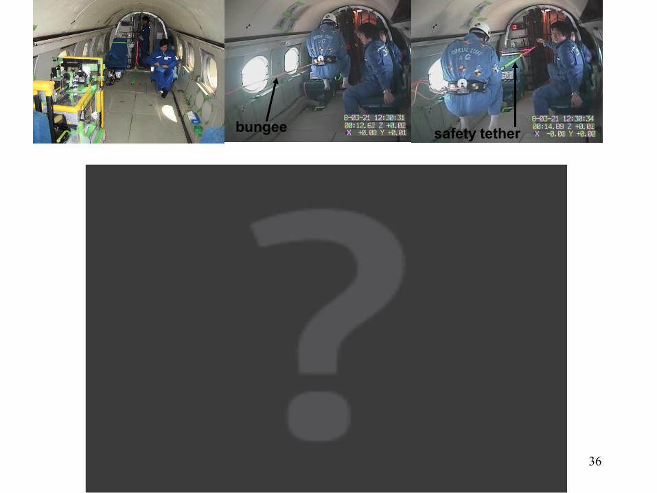
36
bungee safety tether

37
Uncertainty Evaluation
The standard deviation of Er 0.021 (2.1%) and the mean value of Er -0.003 (-0.3%) can be considered as the random error and the systematic error, respectively.
On the other hand, the relative standard uncertainty for calibrating the target mass is negligible (0.01%).
Therefore, the relative standard uncertainty of the mass estimated using data from a single sliding measurement is estimated to be 0.021 (2.1%).
As the mean value of the relative measurement error is much smaller than the standard deviation, the measurement error can be reduced by conducting multiple measurement runs and averaging the results.

38
39
Discussions
The measurement error is thought to derive mainly from the uncertainty of the noisy acceleration field of the aircraft.
On the ISS, where a stable microgravity environment is available, a measurement uncertainty better than 1% will be easily obtained using the prototype developed.
The developed Space Scale is also suitable for measuring the mass of large objects such as garbage containers and bags.
The total mass of the instrument can be made as small as 1kg by introducing a laser diode interferometer, a small force transducer, and a digital signal-processing unit.