Instructions for Use...Roche February 2014 Instructions for Use · Version 14.0 7 cobas b 221 system...
360
cobas b 221 system Instructions for Use
Transcript of Instructions for Use...Roche February 2014 Instructions for Use · Version 14.0 7 cobas b 221 system...

cobas b 221 system
Instructions for Use

COBAS, COBAS B and LIFE NEEDS ANSWERS are trademarks of Roche.
©2014 Roche
Roche Diagnostics GmbHSandhofer Strasse 116D-68305 MannheimGermanywww.roche.com

Roche Diagnostics February 2014
Instructions for Use · Version 14.0 3
cobas b 221 system
Revision History
Edition notice
cobas b 221 system
In the course of 2006 the Roche OMNI S system was relaunched under the Roche professional IVD user brand cobas®.
Systems with a serial number of 5001 or above are cobas b 221 systems.
Systems with a serial number up to 5000 are Roche OMNI S systems.
Every effort has been made to ensure that all the information contained in this manual is correct at the time of printing. However, Roche Diagnostics GmbH reserves the right to make any changes necessary without notice as part of ongoing product development.
Any customer modification to the instrument will render the warranty or service agreement null and void.
Software updates are done by Roche Service representatives.
Manual Version Software Version Revision date Changes
2.0 1.0 May 2003 Launch
3.0 1.0 June 2003 not delivered
3.1 1.02 July 2003
4.0 2.0 March 2004
5.0 4.0 December 2004
6.0 5.0 November 2005
7.0 5.0 March 2006 cobas Branding
8.0 6.0 December 2006
9.0 7.0 February 2008
10.0 >7.0 April 2009
11.0 >7.06 February 2011
12.0 >7.08 May 2012
13.0 >7.09 October 2012
14.0 >8.0 February 2014
Table 1 Revision history

cobas b 221 system
Roche Diagnostics February 2014
4 Instructions for Use · Version 14.0
Copyright
© 2003-2014, Roche Diagnostics International Ltd. All rights reserved.
The contents of this document may not be reproduced in any form or communicated to any third party without the prior written consent of Roche. While every effort is made to ensure its correctness, Roche assumes no responsibility for errors or omissions which may appear in this document. Subject to change without notice.
Brands
COBAS, COBAS B, LIFE NEEDS ANSWERS, ROCHE OMNI, AUTOQC, ROCHE MICROSAMPLER, COMBITROL and AUTO-TROL are trademarks of Roche.
Contact addresses
Manufacturer
Edition
Revision 14.0, February 2014
First edition: May 2003
Roche Diagnostics GmbHSandhofer Strasse 11668305 MannheimGermany
Made in Switzerland
www.roche.com

Roche February 2014
Instructions for Use · Version 14.0 5
cobas b 221 system
Table of contents
Revision History 3Edition notice 3Copyright 4Brands 4Contact addresses 4Edition 4Table of contents 5Preface 7How to use this manual 7Where to find information 7Conventions used in this manual 7
Introduction and specifications
1 Safety informationImportant information 19Operating safety information 20IT Security Advisory 21
2 General descriptionsIntroduction 25General notes 27Measurement and calibration procedure 29Measurement evaluation 31Safety instructions for specific dangers 32Handling solutions 33Handling electrodes 34General notes on the use of the MSS cassette 35System description 37
3 Installation and shutdownInstallation 45Shutdown 65
4 SpecificationsPerformance data 79Sample throughput 103Measurement times of the samples 104Sample volumes 105Sample types 106Calibrations 107Environmental parameters 108Product data 111AutoQC 112Printer 112Touch screen-PC unit 113Barcode scanner 114
5 Theoretical foundationsParameters and calculations 117Reference and critical values 132
Operation
6 MeasurementPreanalytics 145Interferences 151Limitations of clinical analysis 157Measuring procedure 160Aspirate from syringe 163Use as default setup 165Data input 166POC mode (Point-of-care mode) 171
7 Quality controlQuality control - general 175General QC concept 176Important information concerning the analysis of QC measurement results 178Material setup 179Material assignment – AutoQC materials 181QC timing 184Setting start time(s) 185Change lot (applies only to AutoQC measurements) 186Control - on board time 188Scanning the material code 190Scanning ranges 191Checking for AutoQC compatibility 192QC measurement 196AutoQC measurement 198Multirules 199Overview of the Multirules 200QC consequences 201Remove the QC lock 202Exchange the electrode 203QC for Ready (with AutoQC module) 204QC for Ready (without AutoQC module) 206QC troubleshooting 208
8 CalibrationCalibration - general 213Automatic calibrations 213User-activated calibrations 214Display of parameters during calibration 216
9 Software modesSoftware modes - general 219User interface 219Parameters/icons 221Analyzer mode 226Setup 228Data manager 229Info 235

Roche February 2014
6 Instructions for Use · Version 14.0
cobas b 221 system
Maintenance
10 MaintenanceMaintenance - general 247Decontamination 247Daily 249Weekly 250Quarterly 252Sample-dependent maintenance procedures 256Unscheduled 265Additional maintenance procedures 286
Troubleshooting
11 TroubleshootingTroubleshooting - general 293System stops 294Module stops 300System warnings 304Status messages of measuring and calibration values 308Status messages on the measurement report 324Barcode 325
Appendix
12 List of consumablesOrder information 331
13 Glossary
Index
Index 341
Revisions
13 RevisionsRevision 351

Roche February 2014
Instructions for Use · Version 14.0 7
cobas b 221 system
Preface
The cobas b 221 system is an analyzer with integrated AutoQC drawer option.
This manual has detailed descriptions of cobas b 221 system features and general operational concepts, specification functions and use of controls, operating techniques, emergency procedures, product labeling and maintenance procedures.
How to use this manual
Q o Keep this manual in a safe place to ensure that it is not damaged and remains available for use.
o This Instruction for Use should be easily accessible at all times.
To help you find information quickly, there is a table of contents at the beginning of the book and each chapter. In addition, a complete index can be found at the end.
Where to find information
In addition to the Instruction for Use, the following documents are also provided to assist in finding desired information quickly:
o cobas b 221 system Reference Manual
o cobas b 221 system Short Instruction
Conventions used in this manual
Visual cues are used to help locate and interpret information in this manual quickly. This section explains formatting conventions used in this manual.
Symbols Helping to locate and interpret information in this manual the following symbols are used:
Symbol Used for
a Procedural step
o List item
e Cross-reference
h Call up of screen
Note
Table 2 Symbols

cobas b 221 system
Roche February 2014
8 Instructions for Use · Version 14.0
IVD symbols The symbols are used in accordance with DIN EN 980(1) and DIN EN ISO 780(2).
Attention
All sections/passages that are marked with this symbol describe procedures and/or indicate conditions or dangers that could damage or lead to a malfunction in the cobas b 221 system.
Warning
Sections marked with this symbol contain information that must be observed to avoid potential injuries (to patients, users and third parties).
Risk of infection
All sections and parts of texts that are marked with this symbol describe procedures that may involve risk of infection.
ESD protective measures
All sections/text passages that are marked with this symbol refer to components that require special care with respect to electrostatic discharges. Packaging with this label may be opened by trained personnel only.
Symbol Used for
Table 2 Symbols
(1) DIN EN 980: Medical devices - Symbols to be used with medical device labels, labelling and information
to be supplied (Part 1: General requirements)
(2) DIN EN ISO 780: Packaging - Pictorial marking for the handling of goods
Symbol Description
Conformité Européenne:
This product complies with the requirements in the guideline for In Vitro Diagnostic 98/79/EC.
Batch code
Use by...
The product should not be used after expiry of the specified date.
If a day is not indicated, apply the last day of the respective month.
Temperature limitation
The conditions necessary to preserve the product's shelf life before opening.
In Vitro Diagnostic Medical Device
Manufacturer
(according to In Vitro Diagnostic guidelines 98/79/EG)
Catalogue number
Serial number (model plate)
Caution, consult accompanying documents
Please consult instructions for use
Table 3 IVD symbols

Roche February 2014
Instructions for Use · Version 14.0 9
cobas b 221 system
Biological risk
(according to the standard IEC/EN 61010-2-101)(1)(Instrument)
Biological risk
(according to the standard DIN EN ISO 980)(2)(Consumables)
Do not use if package is damaged
Do not reuse
Fragile. Handle with care
Handle with care
Valid only for Roche MICROSAMPLER PROTECT:
Method of sterilization using ethylene oxide
Valid only for BS2 Blood Sampler:
Method of sterilization using irradiation
(1) IEC/EN 61010-2-101: Safety requirements for electrical equipment for measurement, control, and laboratory use - (Part 2-101: Particular requirements for in vitro diagnostic (IVD) medical equipment).
(2) DIN EN ISO 980: Medical devices - Symbols to be used with medical device labels, labelling and information to be supplied (Part 1: General requirements).
Symbol Description
Table 3 IVD symbols

cobas b 221 system
Roche February 2014
10 Instructions for Use · Version 14.0
Other symbols The following symbols are listed as additional information:
Abbreviations The following abbreviations are used:
Symbol Description
Electrodes:
This date indicates the limit of the maximum storage time of an electrode. The electrode must be installed in the instrument no later than the imprinted date.
If the installation takes place on the imprinted date, it still falls within the specifications. The calculation of the “Install before” date is based on the production date of the electrode.
Danger symbol: "Irritant" (on the label and the packaging of S2 Fluid Pack)
Rating: Although not corrosive, momentary, longer-lasting, or repeated contact with skin or mucous membrane may result in inflammation. Danger of sensitization during contact with skin (when classified with R 43).
Caution: Avoid contact with eyes and skin, do not inhale vapors.
Danger symbol: "Corrosion" (on the label and the packaging of S2 Fluid Pack)
Hazard statement: Causes severe skin burns and eye damage.
Prevention: Avoid contact with eyes and skin, do not swallow or inhale vapor. Wear protective, gloves, clothing, eye and face protection.
Warning symbol: "Exclamation mark" (on the label and the packaging of S2 Fluid Pack)
Hazard statement: Harmful if swallowed.
Prevention: Wash thoroughly after handling. Do not eat, drink or smoke when using this product..
Invisible Laser Radiation
Avoid direct radiation to eyes.
Laser Class 3R according to EN 60825-1P0 5 mW = 635 - 850 nm
Store upright
"Grüner Punkt" (in Germany)
Protective gloves, protective goggles and suitable protective clothing must be worn.
Table 4 Other symbols
Abbreviation Definition
A
ANSI American National Standards Institute
AQC, AutoQC Automatic Quality Control
Table 5 Abbreviations

Roche February 2014
Instructions for Use · Version 14.0 11
cobas b 221 system
ASTM American Society for Testing and Material
B
BG Blood gas
BUN Blood urea nitrogen
C
CE Conformité Européenne
CLIA Clinical Laboratory Improvement Amendments
CLSI Clinical and Laboratory Standards Institute
COHb Carboxyhemoglobin
cond Conductivity
COOX CO-Oximetry
CSA Canadian Standards Association
D
dBA Decibel weighted against the A-frequency response curve. This curve approximates the audible range of the human ear.
DIL Diluent
DIN German Institute for Standardization
DNS Domain Name Server
E
EC European community
e.g. for example
EN European standard
F
FMS Fluid mixing system
G
GB Gigabyte
Glu Glucose
H
Hct Hematrocrit
HHb Desoxyhemoglobin
HIV Human immunodeficiency virus
HW Hardware
Hz Hertz
I
i.e. that is to say
IEC International Electrotechnical Commission
ISE Ion selective electrode
ISO International Organization of Standardization
IVDD In vitro Diagnostic Directive
K
KCl Potassium chloride
kg kilogram
L
Abbreviation Definition
Table 5 Abbreviations

cobas b 221 system
Roche February 2014
12 Instructions for Use · Version 14.0
Lac Lactate
LCD Liquid crystal display
LED Light emitting diode
LIS Laboratory Information System
LJ Levey Jennings
LoD Limit of Detection
M
MAC Media Access Control
MB Megabyte
MC Measuring chamber
MetHb Methemoglobin
MHz Megahertz
MSDS Material safety data sheet
MSS Metabolite sensitive sensor
MV Mean value
N
NIST National Institute of Standards and Technology
NRTL Nationally Recognized Testing Laboratory
O
O2Hb Oxyhemoglobin
P
PCO2 Partial pressure of carbon dioxide
PO2 Partial pressure of oxygen
PP Peristaltic pump
Q
QC Quality control
R
RCon Reference contact
REF Reference solution
S
SCon Sensor contact
SD Standard deviation
SDC Sample distributor cartridge
SIP Sample inlet path
SO2 Oxygen saturation
S1 S1 Rinse Solution
S2 S2 Fluid Pack
S3 S3 Fluid Pack
T
T&D Turn & dock
tHb Total hemoglobin
U
USB Universal Serial Bus
Abbreviation Definition
Table 5 Abbreviations

Roche February 2014
Instructions for Use · Version 14.0 13
cobas b 221 system
U For writing the measuring, calculated and input values see Software modes (p. 217) >
Parameters/icons (p. 221)
V
VDE Association of German Electrical Engineers
W
W Watt
Abbreviation Definition
Table 5 Abbreviations

cobas b 221 system
Roche February 2014
14 Instructions for Use · Version 14.0

February 2014
Introduction and specifications
1 Safety information ........................................................................................................................... 17
2 General descriptions......................................................................................................................... 23
3 Installation and shutdown............................................................................................................... 43
4 Specifications .................................................................................................................................... 75
5 Theoretical foundations ................................................................................................................. 115


Roche February 2014
Instructions for Use · Version 14.0 17
cobas b 221 system 1 Safety informationTable of contents
Safety information 1
The information provided in this chapter is essential for the safe, trouble-free operation of the instrument and must be read and understood by the user.
In this chapter Chapter 1Important information ........................................................................................................19
Operating safety information .............................................................................................20
IT Security Advisory............................................................................................................21
Description......................................................................................................................21
Security precautions.......................................................................................................21

Roche February 2014
18 Instructions for Use · Version 14.0
1 Safety information cobas b 221 systemTable of contents

Roche February 2014
Instructions for Use · Version 14.0 19
cobas b 221 system 1 Safety informationImportant information
Important information
These Instructions for Use contain vital warnings and safety information.
This instrument is intended to be used only for the specialized purpose described in the instructions. The most important prerequisites for use, operation, and safety are explained to ensure smooth operation. No warranty or liability claims will be covered if the machine is used in ways other than those described or if the necessary prerequisites and safety measures are not observed.
The instrument may be operated only by persons whose qualifications enable them to comply with the safety measures that are necessary during operation of the instrument.
Suitable protective equipment, like laboratory clothing, protective gloves, protective goggles and if necessary mouth protectors, must be worn to prevent direct contact with biological working materials. In addition, a face mask is required if there is a risk.
Adjustments and maintenance performed with covers removed and power connected may be attempted only by a qualified technician who is aware of the associated dangers.
Instrument repairs are to be performed only by the manufacturer or qualified service personnel.
Only accessories and supplies either delivered by or approved by Roche are to be used with the instrument. These items are manufactured especially for use with this instrument and meet the highest quality requirements.
Operation of the instrument with solutions whose composition is not consistent with that of the original solutions can negatively affect the long-term measurement accuracy. Deviations in the composition of the solutions can also decrease the service life of the electrodes.
In order to ensure the quality of the measurement results, complete a quality control test on 3 levels (1 = low, 2 = normal, 3 = high) after each electrode exchange, after each exchange of solutions and packs and after startup of the instrument (switched off more than 24 hours).
Additionally complete a quality control test on one level between two automatic 2P calibrations. The levels have to be alternated (1 = low, 2 = normal, 3 = high).
Since the measurements of the instrument depend not only on the correct characteristic function, but also on a series of marginal conditions (e.g. pre-analysis), results obtained from the instrument should be submitted for an expert opinion before taking additional measures based on the supplied measurements.
CAUTION
Caution (refer to accompanying documents)
r Please refer to safety-related notes in the manual accompanying this instrument.

Roche February 2014
20 Instructions for Use · Version 14.0
1 Safety information cobas b 221 systemOperating safety information
Operating safety information
The instrument has been constructed and tested according to the following European Standards:
o IEC/EN 61010-1(1)
o IEC/EN 61010-2-101(2)
o IEC/EN 61010-2-081(3)
It was delivered from the factory in flawless condition with regards to safety features. In order to preserve this condition and ensure safe operation, the user must respect the notices and warnings that are contained in these Instructions for Use.
o This equipment is a Class I laser product according to IEC /EN 61010-1, and it complies with FDA Radiation Performance Standards, 21 CFR Subchapter J (only valid for cobas b 221<1> system, cobas b 221<3> system and cobas b 221<5> system with tHb/SO2 module)(4).
o This instrument is classified under the protection class I according to IEC/EN 61010-1.
o The instrument meets the conditions for overvoltage category II.
o The instrument meets the conditions for contamination level 2.
o Do not operate the instrument in an explosive environment or in the vicinity of explosive anesthetic mixtures containing oxygen or nitrous oxide.
o If objects or liquids enter the internal areas of the instrument, remove the instrument from its power supply and allow an expert to check it thoroughly before using it again.
o The instrument is suitable for long-term operation indoors.
WARNING
Warning
r The power cord must be plugged into a grounded power receptacle. When using an extension cord, make sure it is properly grounded.
r Any rupture of the ground lead inside or outside the instrument or a loose ground connection may result in hazardous operating conditions for the operating personnel. Intentional disconnection of the grounding is not permitted.
r The instrument is not suitable for operation with a direct current power supply. Use only the original power plug delivered with the cobas b 221 system.
r The use of controls or adjustments or performance of procedures other than those specified herein may result in hazardous radiation exposure.
(1) IEC/EN 61010-1: Safety requirements for electrical equipment for measurement, control and
laboratory use (Part 1: General requirements)
(2) IEC/EN 61010-2-101: Safety requirements for electrical equipment for measurement, control, and
laboratory use (Part 2-101: Particular requirements for in vitro diagnostic (IVD) medical equipment)
(3) IEC/EN 61010-2-081: Safety requirements for electrical equipment for measurement, control and
laboratory use (Part 2-081: Particular requirements for automatic and semi-automatic laboratory
equipment for analysis and other purposes)
(4) are no longer manufactured or offered.

Roche February 2014
Instructions for Use · Version 14.0 21
cobas b 221 system 1 Safety informationIT Security Advisory
IT Security Advisory
Description
All devices based on common off-the-shelf operating systems (Microsoft Windows, Linux, etc.) with the capability to connect external storage devices (USB memory drives/sticks, hard disks, floppy disks, CD-ROM, DVS, cameras, PDA, wireless communication devices, etc.) are concerned. This usually applies but is not limited to all products which come with a PC or notebook.
External storage media can be infected with and transmit computer malware (e.g. Virus, Trojan Horse, Spyware, etc.)
cobas b 221 system does not contain anti-virus protection software. Therefore, it is essential to follow the necessary precautions listed below to prevent the transmission of malware.
Security precautions
WARNING
Warning
r Failure to observe the following recommendations may result in data loss, loss of integrity of patient results or unavailability of the system, which may put patients at risk.
o Check all external storage devices with an anti-virus program (on another PC) to ensure that they are malware free before using them on the system.
o Recheck the external storage device between use on different systems in order to avoid cross-interference.
o At no time should portable storage media, particularly USB memory drives/sticks, be used at home or at public computer systems and then be used to connect to a work or customer system.
o Do not use the USB ports to connect other external storage devices unless stated in cobas b 221 system-specific documentation.
o Keep all external storage devices in a secure place so that they can be accessed only by authorized personnel.
o Do not add, move or delete any files or software unless stated in cobas b 221 system-specific documentation.
o Never copy and install any non-Roche software on the system.
o If a system requires additional software please contact the appropriate system hot line.
o Use any remote services capability (e.g. cobas® e-support) only to connect to the Roche Service Network.
o Do not connect to the Internet unless stated in cobas b 221 system-specific documentation.
o Make sure only validated computers are connected to the instrument system network.

Roche February 2014
22 Instructions for Use · Version 14.0
1 Safety information cobas b 221 systemIT Security Advisory
o Ensure other computers on attached networks (e.g. the LIS, FTP) are properly secured and protected from malware. This is the responsibility of the customer and their IT specialists.
o The use of a cobas IT firewall is strongly recommended or even mandatory depending on the system installation.

Roche February 2014
Instructions for Use · Version 14.0 23
cobas b 221 system 2 General descriptionsTable of contents
General descriptions 2
This chapter contains a general description of the instrument, as well as precautionary measures against special dangers and the proper handling of sensors, solutions and the MSS cassette.
In this chapter Chapter 2Introduction..........................................................................................................................25
General notes ........................................................................................................................27
Application area..............................................................................................................27
Operating instructions ..................................................................................................27
Important buttons on the screen..................................................................................28
Measurement and calibration procedure ..........................................................................29
Measurement procedure ...............................................................................................29
Calibration procedure....................................................................................................29
Measurement evaluation .....................................................................................................31
Safety instructions for specific dangers .............................................................................32
Handling samples...........................................................................................................32
Disposal of waste water, bottles, packs, electrodes and the instrument..................32
Decontamination ...........................................................................................................32
Handling solutions ...............................................................................................................33
Handling electrodes .............................................................................................................34
General notes on the use of the MSS cassette...................................................................35
MSS cassette removed from the measuring chamber ...............................................35
Incompatible substances ...............................................................................................35
Inserting the MSS cassette ............................................................................................36
System description ...............................................................................................................37
Visual identification.......................................................................................................37
Screen/PC unit................................................................................................................37
Printer..............................................................................................................................38
Measuring chamber .......................................................................................................38
tHb/SO2 module ............................................................................................................38
COOX module................................................................................................................38
Pumps ..............................................................................................................................39
Input unit ........................................................................................................................39
Bottle compartment .......................................................................................................39

Roche February 2014
24 Instructions for Use · Version 14.0
2 General descriptions cobas b 221 systemTable of contents
Reverse side.....................................................................................................................39
Power supply.............................................................................................................40
Interfaces ...................................................................................................................40
Barcode scanner .......................................................................................................41
Warning and identification labels (including nameplate) ..................................42

Roche February 2014
Instructions for Use · Version 14.0 25
cobas b 221 system 2 General descriptionsIntroduction
Introduction
Figure 2-1 cobas b 221 system
The cobas b 221 system is an analyzer with integrated AutoQC drawer option. Depending on combination and configuration, the following parameters can be measured in human whole blood, serum, plasma, acetate and bicarbonate containing dialysis solutions and QC materials:
o pH
o Blood gas BG (PO2, PCO2)
o Electrolyte ISE (Na+, K+, Cl–, Ca2+)
o Hematocrit (Hct)
o Metabolite MSS
Q Urea/BUN - only cobas b 221<6> system
o Total hemoglobin (tHb)
o Oxygen saturation (SO2)
o Hemoglobin derivative COOX (O2Hb, HHb, COHb, MetHb)
o Bilirubin (neonatal)
The following configurations are available:
During the measurement or calibration or other processes, it is possible to conduct database operations, perform certain settings or call up general information at the same time.
U For details see Software modes (p. 217)
The individual, mutually independent software modes are defined as follows:
o cobas b 221<1> system(1)
(1) are no longer manufactured or offered.
BG, pH, tHb/SO2
o cobas b 221<2> system BG, pH, COOX, Bili
o cobas b 221<3> system (1) BG, pH, ISE, Hct, tHb/SO2
o cobas b 221<4> system BG, pH, ISE, Hct, COOX, Bili
o cobas b 221<5> system(1) BG, pH, ISE, Hct, MSS, tHb/SO2
o cobas b 221<6> system BG, pH, ISE, Hct, MSS, COOX, Bili

Roche February 2014
26 Instructions for Use · Version 14.0
2 General descriptions cobas b 221 systemIntroduction
o Analyzer Measuring, QC measurement, system, calibration, commonly used functions (quick access)
o Setup Instrument settings
o Database Data about patients, measurements, calibrations, QC, and the instrument
o Info

Roche February 2014
Instructions for Use · Version 14.0 27
cobas b 221 system 2 General descriptionsGeneral notes
General notes
Application area
The instrument has been tested for measuring parameters in whole blood, serum, plasma and dialysis solutions (electrolytes only) and the validity of measurements was tested accordingly.
In order to achieve accurate measurements of recommended aqueous control solutions (with regards to deviations from biological samples), choose the proper components and make the corresponding corrections in the QC measurement mode.
The accuracy of measurement values of undefined aqueous solutions cannot be guaranteed (e.g. due to the possibility of interfering components and/or missing or insufficient buffer systems, and/or differences in ionic strength and diffusion potential when compared to biological samples).
Operating instructions
The cobas b 221 system should be switched on at all times.
If the instrument is switched off for an extended period of time (more than 24 hours), a shutdown must be performed.
U For additional information, see Installation and shutdown (p. 43), section Installation
(p. 45) and Shutdown (p. 65).
Prevent any other liquids from entering the instrument except samples and QC material at the fill port.
In order to ensure the quality of the measurement results, complete a quality control test on 3 levels (1 = low, 2 = normal, 3 = high) after each electrode exchange, after each exchange of solutions and packs and after startup of the instrument (switched off more than 24 hours).
Additionally complete a quality control test on one level between two automatic 2P calibrations. The levels have to be alternated (1 = low, 2 = normal, 3 = high).
U For additional information, see Quality control (p. 173).
With Software V 6.0 onwards, using cobas bge link software, the instrument can be monitored from one location, any disturbances can be remedied and the analytical quality monitored.
cobas bge link software is a remote monitoring and remote maintenance software for Roche Point-of-Care analyzers.
U see Figure 2-2 (p. 28)

Roche February 2014
28 Instructions for Use · Version 14.0
2 General descriptions cobas b 221 systemGeneral notes
Figure 2-2
Confirm the message with [OK] either on the instrument or on the PC. The "screen sharing" symbol is added in the status line.
To avoid multiple operation of the instrument, the message "Screen sharing active" is displayed with a yellow background in the error and message window of the instrument.
CAUTION
Caution
r As long as the "screen sharing" symbol is displayed in the status line, the service connection is active. In order to prevent multiple operation of the instrument, no buttons on the screen should be pressed.
Important buttons on the screen
U For additional information, see section Buttons (p. 224).
A "Screen sharing" Symbol B "Screen sharing" active
A
B
Buttons Description
"Analyzer" active/inactive
"Database" active/inactive
"Setup" active/inactive
"Info" active/inactive
Table 2-1

Roche February 2014
Instructions for Use · Version 14.0 29
cobas b 221 system 2 General descriptionsMeasurement and calibration procedure
Measurement and calibration procedure
Measurement procedure
PO2: Use of the Clark measurement principle: measurement of current generated by
the reduction of oxygen.
PCO2: Use of the Severinghouse principle: potentiometric measurement of the pH
change in the electrode caused by CO2.
pH-, Na+-,K+-, Ca2+- and Cl- electrodes are potentiometric electrodes. Special glasses
are used as the sensitive element for pH and Na+. The potassium and calcium membranes contain special neutral carriers. A special ion exchanger is used for chloride membranes. Calculation of these variables also requires the use of a reference electrode—a permanently contacted chloride electrode in the cobas b 221 system.
Glucose, lactate: Glucose oxidizes to form gluconolacton using atmospheric oxygen and the glucose-oxidase (GOD) enzyme, lactate oxidizes to form pyruvate using the lactate oxidase enzyme.
The generated H2O2 is determined amperometrically by using manganese
dioxide/carbon electrode at 350 mV.
Urea: Urea is broken into ammonia and carbon dioxide through urease. Ammonia and carbon dioxide react through hydrolysis with physiological pH to form ammonia or bicarbonate ions. The ammonia ions can be determined using a potentiometrical ammonia ion-selective electrode. This measurement requires a reference electrode such as those used in ion-selective electrodes.
tHb/SO2: Light absorption in whole blood is measured at four different wavelengths,
the sample is subjected to light radiation and the dispersed light is also evaluated.
COOX: The hemoglobin derivatives and the total bilirubin (= neonatal) are determined spectrophotometrically based on the Lambert-Beer law.
Hematocrit: Measurement of the sample's conductivity in the ISE measuring chamber.
Calibration procedure
tHb and SO2 was calibrated when the instrument was manufactured.
Oxygen (O2): Ambient air and a zero point solution are used to calibrate oxygen.
PCO2, pH, ISE: are calibrated using two solutions mixed under different conditions, thereby avoiding the gas supply which is required by other instruments.
MSS: The calibration is carried out with four (Glu, Lac) or five solutions (Urea/BUN) whose weighing concentrations form the basis for measured value determination.

Roche February 2014
30 Instructions for Use · Version 14.0
2 General descriptions cobas b 221 systemMeasurement and calibration procedure
COOX: Determining the hemoglobin derivatives and the total bilirubin (= neonatal) are carried out spectral-photometrically using a cuvette.

Roche February 2014
Instructions for Use · Version 14.0 31
cobas b 221 system 2 General descriptionsMeasurement evaluation
Measurement evaluation
WARNING
Warning
r The measurement results that are output by the cobas b 221 system must always be checked for plausibility by medical specialists with consideration of the clinical situation of the patient before a clinical decision is made based on the results.
In order to ensure the quality of the measurement results, complete a quality control test on 3 levels (1 = low, 2 = normal, 3 = high) after each electrode exchange, after each exchange of solutions and packs and after startup of the instrument (switched off more than 24 hours).
Additionally complete a quality control test on one level between two automatic 2P calibrations. The levels have to be alternated (1 = low, 2 = normal, 3 = high).
U For detailed information, see Quality control (p. 173).

Roche February 2014
32 Instructions for Use · Version 14.0
2 General descriptions cobas b 221 systemSafety instructions for specific dangers
Safety instructions for specific dangers
Handling samples
While handling samples, all necessary regulations concerning hygiene must be observed. Dangerous pathogenic agents could be present.
U For more detailed information, see Measurement (p. 143)
Disposal of waste water, bottles, packs, electrodes and the instrument
Q Dispose of waste water, bottles, packs, electrodes and the instrument according to local and/or laboratory regulations (biologically contaminated—hazardous waste).
Decontamination
The purpose of this decontamination is to minimize risk when handling items that were in contact with biological samples.
Roche recommends following a decontamination procedure in addition to regulations specific to the laboratory.
These decontamination procedures should be performed periodically to minimize the risk of infections.
U For more detailed information about decontamination, see Maintenance (p. 245)
Always wear gloves

Roche February 2014
Instructions for Use · Version 14.0 33
cobas b 221 system 2 General descriptionsHandling solutions
Handling solutions
Store the cobas b 221 system wash/calibrating solutions according to the specified packaging requirements. The temperature of the solutions should be adapted to the ambient temperature before use.
The shelf life of the solutions is limited.
Please read the bottle label and the packaging for the correct storage temperature and the maximum shelf life.
WARNING
Warning: DO NOT FREEZE
r If frozen, the solution's concentration may change and cause calibration errors.
r Do not use damaged fluid packs (S2 and S3). Do not mix the individual components.
U For "Storage specifications", see Specifications (p. 75).

Roche February 2014
34 Instructions for Use · Version 14.0
2 General descriptions cobas b 221 systemHandling electrodes
Handling electrodes
Store the electrodes according to the packaging specifications.
The shelf life of the electrodes is limited.
Please read the label and the packaging for the correct storage temperature and the maximum shelf life.
U For "Storage specifications", see Specifications (p. 75).
Caution: Installation note for the PCO2 electrode
Insert the electrode into the measuring chamber within 5 minutes of opening the ALU-PE packaging.
A special protective gas atmosphere designed to condition the PCO2 electrode during storage is found inside the ALU-PE packaging.
This gas atmosphere ensures immediate potential stability during insertion of the electrode into the measuring chamber and immediate readiness for measuring the first 2 point calibration.
If more than 5 minutes elapse after opening the ALU-PE packaging, the level of gas conditioning could be lost and the time required for the first-time calibration could be increased.

Roche February 2014
Instructions for Use · Version 14.0 35
cobas b 221 system 2 General descriptionsGeneral notes on the use of the MSS cassette
General notes on the use of the MSS cassette
WARNING
For instrument versions with MSS module only
Attention:
r MSS cassette may only be brought into contact with liquids in the cobas b 221 system while electrodes are changed.
r Replace the MSS cassette within 28 days of installation.
Q After initial contact with liquids, the MSS cassette may no longer be removed from the instrument. It may lead to the destruction of the enzyme sensors.
Storage:
At 2 – 8 °C, maximum of 2 weeks at room temperature.
MSS cassette removed from the measuring chamber
Once an MSS cassette is exposed to liquid, it must not be allowed to dry out under any circumstances since this would destroy the enzymes. The enzymes are equipped with a special protectant prior to shipping for transportation purposes. This protectant is washed out inside the instrument during the warm-up phase and MSS polarization.
Incompatible substances
The following substances may not be introduced into the MSS measuring chamber under any circumstances since they would immediately destroy the MSS sensors or severely impact their functionality.
o Deproteinizer (NaOCl)
o O2 zero point solution
o Cleaning solution
o Na electrode conditioning solution
o Rinse additive
o Solutions containing heavy metals (Ag, Hg, Au, etc., e.g. Thiomersal)
o Cleaning solutions containing detergent (e.g. washing material or liquid detergents)
o All solutions for disinfections (e.g. high-percentage alcohol, glutaric dialdehyde, cresol, etc.)
o Solutions with pH values that deviate greatly from neutral
(e.g. pH value of < 6.0 and > 9.0)
The use of anticoagulants other than those approved by Roche (approved: heparin salts), such as EDTA, citrate, NH4 heparin and glycolysis inhibitor such as NaF and oxalate can lead to erroneous results.

Roche February 2014
36 Instructions for Use · Version 14.0
2 General descriptions cobas b 221 systemGeneral notes on the use of the MSS cassette
Inserting the MSS cassette
Q Hold the MSS cassette only at the designated handle and avoid touching the contacts.
U For a detailed description see section Changing the MSS cassette (cobas b 221<5> system
and cobas b 221<6> system only) (p. 280).

Roche February 2014
Instructions for Use · Version 14.0 37
cobas b 221 system 2 General descriptionsSystem description
System description
Visual identification
For example: cobas b 221<6> system
Figure 2-3 cobas b 221<6> system
Screen/PC unit
The screen/PC unit serves as the graphical user interface.
All information (results, error messages, alarms, warnings, etc.) is displayed on the screen. The screen consists of a color LCD that is covered with a touch-sensitive film ("touch screen").
A Screen/PC unit G S1 Rinse Solution M Input unit
B Reverse side H S2 Fluid Pack N Measuring chambers
C Docking mechanism I S3 Fluid Pack O Printer
D AutoQC drawer J Bottle compartment cover P Pumps
E Barcode scanner K Bottle compartment
F W Waste container L COOX module (tHb/SO2 module)
A
B
D
C
E
F G H I
J
K
LM
N
O
P
D

Roche February 2014
38 Instructions for Use · Version 14.0
2 General descriptions cobas b 221 systemSystem description
CAUTION
Caution
r As sharp objects can damage the touch-sensitive film, only touch the film using suitable pins and/or with your fingers.
The screen/PC unit also contains a diskette drive.
Printer
Low-noise thermoprinter with integrated paper cutter (manually activated using the "Cut" key) and optional winder.
The "Feed" key feeds in the paper.
CAUTION
Caution
r With an installed winder, the "Automatic Cut" function is deactivated.
Measuring chamber
Underneath the top cover are the BG and, depending on the configuration, ISE measuring chamber with the electrodes, the MSS measuring chamber with the MSS cassette and the tHb/SO2 or COOX module.
The electrodes are flow-through electrodes with a visible sample channel.
tHb/SO2 module
Figure 2-4 tHb/SO2 module
The tHb/SO2 module is an optical sensor module for determining the level of total
hemoglobin (tHb) and oxygen saturation (SO2) in whole blood.
COOX module
The COOX module consists of the hemolyzer and the COOX measuring chamber. The measurement is based on the principle of spectral photometry.

Roche February 2014
Instructions for Use · Version 14.0 39
cobas b 221 system 2 General descriptionsSystem description
Pumps
Depending on the configuration, up to three peristaltic pumps transport the sample and the operating fluids inside the instrument.
Input unit
The sample insertion as well as the aspiration of solutions is carried out via input unit which consists of the following:
o T&D module:
O T&D disk
O T&D tubing set with wash-water jet
O Plug control
O Fill port
o Sample drip tray
Bottle compartment
Behind the bottle compartment cover are the S1 Rinse Solution bottle, the S2 Fluid Pack, the W Waste Container and, depending on the configuration, S3 Fluid Pack (cobas b 221<5> system and cobas b 221<6> system only).
Reverse side
Figure 2-5 Reverse side
A Power supply D Air filter
B Main power switch and connector E Interfaces
C Warning and identification labels
E
D
C
A
B

Roche February 2014
40 Instructions for Use · Version 14.0
2 General descriptions cobas b 221 systemSystem description
Power supply
This unit also contains the main power switch and the connector.
Figure 2-6 Power supply
Interfaces
Figure 2-7 Interfaces (without USB)
Figure 2-8 Interfaces (with USB)
A Power supply
B Main power switch OFF
C Main power switch ON
AB C
A Power supply D Ext. keyboard/barcode scanner
B Service connector E RS 232
C RS 232 F 10BaseT
A Power supply D RS 232
B Service connector E USB
C Ext. keyboard/barcode scanner F 10BaseT
A B C D E F
A B C D E F

Roche February 2014
Instructions for Use · Version 14.0 41
cobas b 221 system 2 General descriptionsSystem description
o Variant 2:
2x RS 232 interfaces (COM 1 and COM 2) (SN < 1500)
U see Figure 2-7 Interfaces (without USB) (p. 40)
o Variant 1:
1x RS 232 interface (COM 1) and 1x USB (SN > 1500)
U see Figure 2-8 Interfaces (with USB) (p. 40)
o 1x 10BaseT Ethernet (RJ45)
o Ext. keyboard/barcode scanner: PS/2 DIN - 6 pin female connector
o 1 service connector
o Power (power supply is connected)
CAUTION
Caution
r No reverse compatibility from Variant 2 to Variant 1 possible.
Barcode scanner
Figure 2-9 Barcode scanner
o Scanning of electrode data (type, lot, expiration date)
o Scanning of patient or user identity
o Scanning of QC data (QC material, lot, basis, expiration date, target values, etc.)
o Scanning of desired alphanumeric code
Q Press the button on the underside to activate the scanner, a beeping sound and a brief illumination of the LED on the upper side indicate the successful scanning of the barcode.
For more detailed information, please see enclosed manual of the PS2 hand-held scanner (included in scope of delivery).

Roche February 2014
42 Instructions for Use · Version 14.0
2 General descriptions cobas b 221 systemSystem description
Warning and identification labels (including nameplate)
Figure 2-10

Roche February 2014
Instructions for Use · Version 14.0 43
cobas b 221 system 3 Installation and shutdownTable of contents
Installation and shutdown 3
In this chapter, the software-guided installation and shutdown of the instrument are described step by step. The sequence of the steps described must be strictly followed.
In this chapter Chapter 3Installation.............................................................................................................................45
Location...........................................................................................................................45
Accessories ......................................................................................................................46
Procedure ........................................................................................................................47
Shutdown...............................................................................................................................65
Less than 24 hours..........................................................................................................65
Longer than 24 hours.....................................................................................................65

Roche February 2014
44 Instructions for Use · Version 14.0
3 Installation and shutdown cobas b 221 systemTable of contents

Roche February 2014
Instructions for Use · Version 14.0 45
cobas b 221 system 3 Installation and shutdownInstallation
Installation
Location
Q Note
Never set up the cobas b 221 system in the immediate vicinity of patients. Maintain a safety distance of 1.5 meters (5 feet).
For best results, a suitable, level location that is not subject to direct sunlight is required for the instrument.
When installing an instrument that was stored in a cool room or was transported at low temperatures, be aware that condensation may have formed and could cause disturbances to the instrument. The instrument must be climatized at room temperature for at least one hour before beginning operation.
The following conditions must be fulfilled:
o Ambient temperature: 15 °C to 31 °C
o Ambient air pressure: 797 - 526 mmHg (106.225 - 70.13 kPa)
CAUTION
Caution
r From approximately 3000 m above sea level or air pressure < 526 mmHg (70.13 kPa), the specifications for parameter PO2 are no longer fulfilled and the parameter must no longer be used for evaluation of the clinical decisions.
r After successful installation, the parameter must be permanently deactivated.
U See section 24. Checking the barometer value (p. 63)
o Avoid direct sunlight, vibration and strong electromagnetic fields (electric motors, transformers, X-ray equipment, cellular phones...).
o A stable and level work surface (max. 1° incline with bottles installed)
o Relative humidity: 20 to 85%
o For proper air circulation and the electrical connections, the following clearances should be observed around the instrument:
O 8 cm on each side
O 15 cm behind the instrument
O 13 cm above the instrument
o Correct voltage: 100 to 240 VAC (±10%), 50 - 60 Hz
After the cobas b 221 system has been set up at a location that meets the necessary conditions, carry out the following steps to prepare the instrument for operation:
o First, check the instrument and accessories for completeness and potential damage. Verify that the shipment is complete by comparing components with the shipping order.
If anything is missing, inform the Roche representative immediately.
If the delivery has suffered damage despite careful packing, inform the transportation company immediately. Retain the packing material and products as evidence for the damage claim.

Roche February 2014
46 Instructions for Use · Version 14.0
3 Installation and shutdown cobas b 221 systemInstallation
CAUTION
Caution
r Do not under any circumstances insert consumables into the instrument if the packaging of these consumables suffered massive damage.
Using damaged consumables can cause malfunctions of the instrument.
WARNING
Warning
r Handle the instrument only at the specified holding points — risk of injury.
r Take care when lifting - weight of the instrument without wash/calibrating solutions and AutoQC is approximately 45 kg.
Accessories
The following parts are delivered as standard equipment with the cobas b 221 system:
o 1 barcode scanner
o 2 Power cords (US and European version)
o 1 roll printer paper
o 2 pcs fill port
o 1 sample inlet path (glass tube)
o 1 RCon (reference contact)
o 1 shutdown kit
o 1 dummy electrode
o 1 dummy MSS cassette
o 2 SCon (sensor contact)
o 3 pump tubes
Q Not shown in Figure 3-1 Accessories (p. 46):
o 1 screen/PC unit
o 1 power supply
o 1 fill port
Figure 3-1 Accessories

Roche February 2014
Instructions for Use · Version 14.0 47
cobas b 221 system 3 Installation and shutdownInstallation
Procedure
P 1. Screen/PC unit
CAUTION
Caution
r Ensure that the printed serial number on the rear of the screen/PC unit is the same as the unit serial number on the nameplate.
1 Unscrew the fixing nut from the screen.
2 Place the screen/PC unit on the swivel arm.
3 At the base of the swivel arm, place the brake packet and lock nut on the shaft and tighten using the 13 mm wrench provided in the accessories.
Figure 3-2 Swivel arm of the Screen/PC unit
4 Connect the cable to the screen and push it into the cable routing bar.
S
P 2. Power supply
1 Place the power supply, including the two adapter connectors, on the holder and position them.
Figure 3-3 Power supply
A Screen/PC unit C Fixing nut
B Swivel arm D Brake packet
A
B
CD
A Screw B Holder
B B
A

Roche February 2014
48 Instructions for Use · Version 14.0
3 Installation and shutdown cobas b 221 systemInstallation
2 Tighten the screw.
S
P 3. Attach power cord and barcode scanner
1 Connect the power cord.
2 Connect the barcode scanner, and, if necessary, the network connection to the appropriate port on the rear side of the cobas b 221 system.
S
P 4. Switch on
1 Switch the instrument on and wait until the program has completely loaded and started. Before starting the installation, you must set the language, in which the unit is to be operated, the date and the time.
S
P 5. Installation
1 When carrying out the installation, follow the on-screen instructions.
Q Installation must be carried out completely and may not be interrupted.
Observe the listed sequence while performing the actions.
If the automatic first installation is unsuccessful, you must carry out the installation process manually. To do this, press the following buttons:
[System] > [Utilities] > [Installation]
2 Processing the actions manually
Manual:
The corresponding line of the list box contains an instruction which must be performed manually. Then press [Confirm action].
3 Automatic:
If there is an automatic sequence for any action, you can start this by clicking [Start process].
S
P 6. Select language
1 Press the following buttons:
h Setup > Instrument > Language
Q If the current language is "English": [Instrument] > [Language]
2 Select the language.
S
If an action has been completed successfully (manually or automatically), this symbol is displayed.

Roche February 2014
Instructions for Use · Version 14.0 49
cobas b 221 system 3 Installation and shutdownInstallation
P 7. Change the keyboard layout language (optional)
Q Changing the keyboard layout language requires a software (SW) restart.
1 Choose the following buttons:
h Setup > Instrument > Select keyboard layout
2 Choose the desired keyboard layout language.
3 Choose the Yes button.
4 Wait for the SW restart procedure to complete.
S
P 8. Set the date and time
1 Press the following buttons:
h Setup > Times & Intervals > Act. time / date
Figure 3-4 Act. time/date
S

Roche February 2014
50 Instructions for Use · Version 14.0
3 Installation and shutdown cobas b 221 systemInstallation
P 9. Cal. intervals & timing
1 Press the following button:
h Setup > Times & intervals > Cal. intervals & timing
Figure 3-5 Cal. intervals
Use this function to enter the automatic calibration times and intervals for system, 1P and 2P calibrations.
The time scale uses markers to show the selected interval for the 2P calibration and the start time for the system calibration.
Intervals:
S
P 10. Set valves for FMS tubing exchange
1 Press [Start process]. This action is performed automatically.
Q Valve V19 is pushed in to prevent the tube from being pinched while the aluminum part is tightened. Valve VM is pushed out.
S
P 11. Fix screws at V19 (bottle compartment)
1 Open the bottle compartment cover and the docking mechanism "S3".
2 Tighten the screws on valve V19 (approximately 2-3 rotations).
U see Figure 3-6 Valve V19 and VM (p. 51)
Q Use the delivered screwdriver.
System calibration Every 8, 12 or 24 hours.Enter the [Start time] of a system calibration to which all calibrations are oriented.
2P calibration Every 4, 8 or 12 hours.
1P calibration All 30 or 60 minutes (USA: only every 30 minutes).

Roche February 2014
Instructions for Use · Version 14.0 51
cobas b 221 system 3 Installation and shutdownInstallation
Figure 3-6 Valve V19 and VM
3 To return to the installation window, close the docking mechanism and the bottle compartment cover.
S
P 12. Insert right FMS tube at VM (bottle compartment)
1 Open the bottle compartment cover and the docking mechanism "S3".
2 Slide the tube under the tube clip of valve VM.
Figure 3-7 Valve VM
Figure 3-8 Valve VM
3 Close docking mechanism and bottle compartment cover.
S
A Screws on valve V19 B
A A
A VM B V19
A B

Roche February 2014
52 Instructions for Use · Version 14.0
3 Installation and shutdown cobas b 221 systemInstallation
P 13. Insert fill port and sample inlet path (glass tube)
1 Pull out the sample drip tray.
2 Remove the T&D cover and the unit cover.
3 Insert the fill port started from the 6 o’clock position as shown below.
4 Push the fill port straight onto the insert needle.
WARNING
Warning
r Do not bend the insert needle during this process.
Figure 3-9 Insert needle
5 Rotate the fill port 90° clockwise and upwards until it snaps into place.
Figure 3-10
6 Open the T&D lock.
U see Figure 3-11 Glass tube (p. 53), A
7 Insert the glass tube into the guides, fasten it and check it for a correct position.
U see Figure 3-11 Glass tube (p. 53), C
U see Figure 3-11 Glass tube (p. 53), D
A Needle
A

Roche February 2014
Instructions for Use · Version 14.0 53
cobas b 221 system 3 Installation and shutdownInstallation
Figure 3-11 Glass tube
8 Close the T&D lock again. Check the correct positioning of the sample inlet path to the bypass nipple (see below).
Figure 3-12 T&D lock
9 Close the T&D cover.
10 Insert the sample drip tray.
S
A T&D lock C Insert the glass tube into the guides
B Glass tube D Fasten and check for correct position
B
A
C
CD
A Bypass nipple
A

Roche February 2014
54 Instructions for Use · Version 14.0
3 Installation and shutdown cobas b 221 systemInstallation
P 14. Insert printer paper
Q The printer paper is heat sensitive on one side only. Observe the correct insertion of the thermal paper roll.
1 Open the printer cover and the paper lid.
Figure 3-13 Printer
2 Cut the start of the paper so that it is straight.
3 Place the paper roll into the holder.
4 Make sure that the printer lever is in the "down" position (see below).
Figure 3-14 Printer lever
5 Insert the beginning of the paper according to the instructions on the inside of the paper lid (see below).
Figure 3-15 Insert printer paper - without take-up unit
A Printer cover B Paper lid
A Printer lever "down" position
A Paper lid B Printer lever
B
A
A
A
B

Roche February 2014
Instructions for Use · Version 14.0 55
cobas b 221 system 3 Installation and shutdownInstallation
Figure 3-16 Insert printer paper - with take-up unit (optional)
6 The paper is automatically pulled into the printer.
7 Close paper lid.
S
P With take-up unit (optional)
1 Press the paper feed button until the paper is long enough.
2 Insert the beginning of the paper in the take-up unit according to the instructions on the inside of the paper lid.
U see Figure 3-16 Insert printer paper - with take-up unit (optional) (p. 55)
Q Press the take-up unit (rods) fully onto the holder and rotate until the paper is taut on the rods and paper lid, so that the entire roll of paper can be taken up. During operation, the paper should be tautened now and then by turning the take-up roller.
3 Close printer cover.
CAUTION
Caution
r With an installed take-up unit, the "Automatic Cut" function is deactivated.
S
P 15. Insert peristaltic pump tubes
1 Open the peristaltic pump's clear plastic cover (tension lever).
2 Push the linear bracket (white plastic part) upwards (see below).
Figure 3-17 Peristaltic pump
A Tension lever
B Pump head
C Linear bracket
A
B
C

Roche February 2014
56 Instructions for Use · Version 14.0
3 Installation and shutdown cobas b 221 systemInstallation
3 Place the tubing set around the corresponding rolling wheel (see below/A). Check that the tubing set is correctly orientated (the grip end must be pointing upwards, see below/B).
4 Close the clear plastic cover (tension lever). The tubing holder is then pressed into the sealer (see below/B).
Figure 3-18 Peristaltic pump
AutoQC module (option)
Q The installation with an AutoQC module (optional) must be performed by a Roche Service Representative.
S
P 16. Go to AutoQC service position
1 Press [Start process]. This action is performed automatically.
S
P 17. Open the AutoQC drawer and remove the AutoQC valve clamp
1 Pull out the AutoQC drawer.
2 Pull the key of the AutoQC valve up and out (see below).
Figure 3-19 AutoQC valve clamp
3 Close the AutoQC drawer.
S
A Place the tubing set B Close the tension lever
A AutoQC valve clamp B
A

Roche February 2014
Instructions for Use · Version 14.0 57
cobas b 221 system 3 Installation and shutdownInstallation
P 18. Go to AutoQC home position
1 Press [Start process]. This action is performed automatically.
S
P 19. Open AutoQC drawer and insert ampoule holder
1 Pull the AutoQC drawer out again.
Figure 3-20 AutoQC drawer
2 Insert the AutoQC ampoule holder.
3 Close the AutoQC drawer.
S
P 20. Open bottle compartment cover and insert Waste container & packs
1 Open the bottle compartment cover.
Figure 3-21 Waste container & packs
2 Open the corresponding docking mechanism.
3 Insert an empty waste water bottle and a S1 Rinse Solution bottle.
CAUTION
Caution
r Remove packs’ rubber seals.
A without ampoule holder B with ampoule holder
A Rubber seals B cobas b 221<5> system and cobas b 221<6> system only
AA
B

Roche February 2014
58 Instructions for Use · Version 14.0
3 Installation and shutdown cobas b 221 systemInstallation
4 Push the two packs into the appropriate location in accordance with the labeling on the docking mechanisms until the packs lock.
Using the transponder attached to the bottle/packs, the instrument automatically recognizes the corresponding bottle or packs.
Figure 3-22 Changing of bottles and packs
Figure 3-23 Bottle compartment
5 Close the docking mechanism and the bottle compartment cover.
Q To avoid splashing the S1 Rinse Solution, deaerate the bottle at about 3000 m above sea level or higher before inserting it.
6 Place the bottle tool on the screw cap of the S1 Rinse Solution (see below).
Figure 3-24 Screw cap
A cobas b 221<5> system and cobas b 221<6> system only
A cobas b 221<5> system and cobas b 221<6> system only
A
A
A Bottle tool B Screw cap with placed bottle tool

Roche February 2014
Instructions for Use · Version 14.0 59
cobas b 221 system 3 Installation and shutdownInstallation
7 Press the grips together and press the transparent disk downward (see below/A).
8 Rotate the transparent disk clockwise and stop when you notice a resistance after a short distance (see below/B).
Figure 3-25 Open bottle
S
P 21. Open the measuring chamber cover and insert the sensors
1 BG/ISE measuring chamber
Open the measuring chamber cover (push the right edge of the MC cover to the left with a finger and open up the MC cover).
Q In each case, open only the relevant measuring chamber.
Keep the bottle compartment cover closed.
The following screen appears:
Figure 3-26 Changing of electrodes
2 Open the locking lever.
U see Figure 3-29 Insertion of the reference electrode (p. 61)
3 Follow the instructions on the screen.
WARNING
Warning
r Check the internal electrolyte of the electrodes for possible air bubbles (see below).
If there are air bubbles between the contact pin and the membrane, there will not be effective electrical conduction. Result: calibration and measurement errors.

Roche February 2014
60 Instructions for Use · Version 14.0
3 Installation and shutdown cobas b 221 systemInstallation
4 Remove any air bubbles.
Remove air bubbles by holding the electrode vertically and by tapping lightly with a fingernail against the electrode body (see below).
Figure 3-27 Electrode
5 Insert the electrodes, beginning at the right and proceeding left according to the color code.
6 Push all electrodes slightly to the right so that they are lined up together without gaps.
S
P Insert the reference electrode
WARNING
Warning
r The reference electrode must be installed in the instrument no later than the imprinted "Install before" date. The reference electrode must be replaced after 52 weeks of in-use time. Therefore, set up an alert in the Maintenance schedule:
U see Setting up the Maintenance schedule (p. 272)
1 Insert the reference electrode.
Figure 3-28 Reference electrode
A Free of air bubbles
A

Roche February 2014
Instructions for Use · Version 14.0 61
cobas b 221 system 3 Installation and shutdownInstallation
2 Insert the reference tube into the upper tube guide channel of the left locking lever and into the tube holder of the cover hinge. Close the locking lever (see below).
Figure 3-29 Insertion of the reference electrode
3 Connect the white connector on the end of the tube to the measuring chamber cassette (see below).
Figure 3-30 Insertion of the reference electrode 2
4 Scan the barcodes located on the inner packaging of each electrode or enter the barcodes manually with the help of the keyboard.
5 Close the measuring chamber cover.
S
P MSS measuring chamber (for instrument versions with MSS module only)
Q Hold the MSS cassette only at the designated handle and avoid touching the contacts.
1 Open the cover of the MSS measuring chamber (apply force to the right edge of the MC cover with a finger to push it to the left and open up the MC cover).
Q Keep the bottle compartment cover closed.
2 Open the contact clip and the locking lever.
A Locking lever
A Connector B Measuring chamber cassette
A
B
A

Roche February 2014
62 Instructions for Use · Version 14.0
3 Installation and shutdown cobas b 221 systemInstallation
3 Depending on the MSS parameter configuration, insert the MSS reference electrode (Ref + dummy) (see Figure 3-31 MSS measuring chamber (p. 62)/A) or the reference contact (RCon) (see Figure 3-31 MSS measuring chamber (p. 62)/B) and the MSS cassette, close the contact clip and the locking lever.
Figure 3-31 MSS measuring chamber
4 Read in the barcode of the packaging.
5 Close the measuring chamber cover.
6 Close the top cover.
7 Prepare a syringe or capillary with whole blood for polarization. Having completed the installation process, the unit requests a blood sample.
S
P 22. Complete installation
1 Press the [Complete installation] button.
Automatic sequences take place and the unit warms up.
2 Installation is complete.
Q If a power failure occurs during installation, the installation starts anew with the next restart. Actions which were performed successfully are discarded.
S
A Ref + dummy (for Glu/Lac/Urea) C Contact clip
B Locking lever D RCon (Glu or Glu/Lac)
A
D
C
B
The blood should have a volume of at least 150 μL, contain heparin as an anticoagulant, and be stored for less than 24 hours.

Roche February 2014
Instructions for Use · Version 14.0 63
cobas b 221 system 3 Installation and shutdownInstallation
P 23. Perform MSS polarization (cobas b 221<5> system and cobas b 221<6> system only)
1 Prepare a syringe or capillary with whole blood for polarization.
Figure 3-32 MSS polarization
2 The blood sample is inserted via fill port similar to a measurement.
U see Measurement (p. 143)
3 The MSS cassette is subsequently exposed to liquid, polarized and heated.
4 A system calibration is carried out.
5 If, after inserting the cassette, the automatic polarization was not successful and the MSS sensors are not calibrated, you must manually polarize the MSS cassette. To do this, press the following buttons:
h System > Utilities > MSS polarization
6 Follow the instructions on the screen.
S
P 24. Checking the barometer value
1 h System > Component test > Control sensors > Baro sensor
If the barometer value deviates by more than ± 4 mbar from the value indicated by a precision barometer, it will be necessary for Technical support to calibrate the barometer.
CAUTION
Caution
r A wrong barometer value leads to wrong PO2 measurement results.
Important:
r From approximately 3000 m above sea level or air pressure < 526 mmHg (70.13 kPa), the specifications for parameter PO2 are no longer fulfilled and the parameter must no longer be used for evaluation of the clinical decisions. The parameter PO2 must be permanently deactivated.
The blood should have a volume of at least 150 μL, contain heparin as an anticoagulant, and be stored for less than 24 hours.

Roche February 2014
64 Instructions for Use · Version 14.0
3 Installation and shutdown cobas b 221 systemInstallation
2 To deactivate the parameter PO2 press the following buttons:
h Setup > Parameter > Miscellaneous settings > Activated/deactivated for calibrations
S
P 25. Quality control
1 Define the material and if an AutoQC drawer (option) is available insert the mats before performing a quality control measurement.
U For details, see Quality control (p. 173)
2 Perform quality control tests for all 3 levels (low, normal, high). Make sure that the results are in line with the target values.
U See Quality control (p. 173)
S

Roche February 2014
Instructions for Use · Version 14.0 65
cobas b 221 system 3 Installation and shutdownShutdown
Shutdown
Less than 24 hours
If the cobas b 221 system is not used for a short period of time only (< 24 hours), then activate the following function, starting with the top level of the analyzer mode:
h System > Utilities > Shutdown PC
This function allows for switching off the touch screen/PC unit and is completed with manually switching off the instrument.
Follow the instructions on the screen.
CAUTION
Caution
r MSS sensors (Glu/Lac/Urea/BUN) are destroyed during this operation.
If the instrument is turned on again, a new MSS cassette must be inserted.
U See section 21. Open the measuring chamber cover and insert the sensors (p. 59).
Longer than 24 hours
If the cobas b 221 system will be shut down for longer than 24 hours, perform the following procedure.
U see section Decontamination (p. 247).
Activate the following function, starting with the top level of the analyzer mode:
h System > Utilities > Put out of operation
WARNING
Warning
r All solutions and electrodes have to be removed during the shutdown procedure.
r The procedure ends in switching off the instrument.
r Follow the instructions on the screen.
Q Observe the listed sequence while performing the actions.
Processing the actions:
Manual: The corresponding line of the list box contains an instruction which must be performed manually. Then press [Confirm action].
Automatic: If there is an automatic sequence for any action, you can start this by clicking [Start process].
Before performing a shutdown, Roche recommends decontaminating all surfaces and tube paths.
Upon successful completion, this symbol is displayed.

Roche February 2014
66 Instructions for Use · Version 14.0
3 Installation and shutdown cobas b 221 systemShutdown
P 1. Open bottle compartment cover and only remove bottle S1 and packs (depending on the configuration S2 and S3).
1 Open bottle compartment cover and docking mechanism and remove bottle S1 and the packs (S2 and S3).
WARNING
Warning
r Do not remove the waste container.
2 Close docking mechanism and bottle compartment cover.
S
P 2. Fill the shutdown kit with distilled water
1 Fill the shutdown kit about halfway with distilled water.
Figure 3-33 Shutdown kit
S
P 3. Insert shutdown kit into space S2
1 Open bottle compartment cover and docking mechanism S2 and insert the shutdown kit into space S2.
2 Close docking mechanism and bottle compartment cover.
3 Perform "Washing of the tubes".
S
P 4. Remove shutdown kit from space S2
1 Open bottle compartment cover and docking mechanism S2 and remove the shutdown kit.
2 Close docking mechanism and bottle compartment cover.
3 Perform "Emptying of the tubes".
S

Roche February 2014
Instructions for Use · Version 14.0 67
cobas b 221 system 3 Installation and shutdownShutdown
P 5. Insert shutdown kit into space S3 (cobas b 221<5> system and cobas b 221<6> system only)
1 Open bottle compartment cover and docking mechanism S3 and insert the shutdown kit into space S3.
2 Close docking mechanism and bottle compartment cover.
3 Perform "Washing of the tubes".
S
P 6. Remove shutdown kit from space S3 (cobas b 221<5> system and cobas b 221<6> system only)
1 Open bottle compartment cover and docking mechanism S3 and remove the shutdown kit.
2 Close docking mechanism and bottle compartment cover.
3 Perform "Emptying of the tubes".
S
P 7. Remove Waste container
1 Open bottle compartment cover and docking mechanism W.
2 Remove the waste water container (W Waste Container).
3 Close docking mechanism and bottle compartment cover.
S
P 8. Open the measuring chamber cover and remove the sensors
1 Remove the top cover and open all measuring chamber covers.
2 Open the measuring chamber cover (push the right edge of the MC cover to the left with a finger and open up the MC cover).
3 Open the locking levers and the contact clip (MSS measuring chamber).
4 Sequentially remove the electrodes and the MSS cassette from the measuring chambers.
5 Close the locking lever, the contact clip and all the measuring chamber covers.
S

Roche February 2014
68 Instructions for Use · Version 14.0
3 Installation and shutdown cobas b 221 systemShutdown
P 9. Remove the peristaltic pump tubes
1 Open the peristaltic pump's clear plastic cover (tension lever) (see below).
Figure 3-34 Peristaltic pump
2 Push the linear bracket (white plastic part) upwards (see below/A).
3 Remove the complete tubing set (tubing holder and tubing) of the corresponding pump (see below/B)
Figure 3-35 Peristaltic pump
4 Close the tension lever.
S
A Tension lever
B Pump head
C Linear bracket
A Push the linear bracket upwards B Remove the tubing set
A
B
C

Roche February 2014
Instructions for Use · Version 14.0 69
cobas b 221 system 3 Installation and shutdownShutdown
P 10. Remove the printer paper
1 Open the printer cover and the paper lid.
Figure 3-36 Printer cover/paper lid
2 Move the printer lever upwards (see below/A).
Figure 3-37 Printer lever
3 Remove the printer paper.
4 Move the printer lever down again (see above/B).
5 Close the paper lid and the printer cover.
S
P 11. Open T&D
1 Press [Start process].
This action is performed automatically. The T&D disk turns to position 1.
S
P 12. Remove fill port and sample inlet path (glass tube)
1 Remove the sample drip tray.
2 Remove the T&D cover.
A Printer cover B Paper lid
A Printer lever "upwards" B Printer lever "down"
B
A

Roche February 2014
70 Instructions for Use · Version 14.0
3 Installation and shutdown cobas b 221 systemShutdown
3 Open the T&D lock and remove the sample inlet path (glass tube).
Figure 3-38 T&D lock & sample inlet path
4 Turn the fill port downward by 90° and pull it straight off of the needle.
Q Do not bend the needle.
Figure 3-39 Fill port
5 Close the T&D lock again.
A T&D lock B Sample inlet path (glass tube)
B
A
A Fill port B Needle
BA

Roche February 2014
Instructions for Use · Version 14.0 71
cobas b 221 system 3 Installation and shutdownShutdown
6 Close the T&D cover.
S
P 13. Set valves for FMS tubing exchange
1 Press [Start process]. This action is performed automatically.
Q Both valves are pushed out.
S
P 14. Release screws at V19 (bottle compartment)
1 Open the bottle compartment cover and the docking mechanism S3.
2 Loosen the screws (A) of the aluminum part of valve V19 (approximately 2-3 turns).
Figure 3-40 Valve V19
3 Close the docking mechanism S3 and the bottle compartment cover.
S
P 15. Remove right FMS tube at VM (bottle compartment)
1 Open the bottle compartment cover and the docking mechanism S3.
2 Slide the tube out under the tube clip of valve VM.
Figure 3-41 Valve VM
3 Pressure is removed from the tubes.
A Screws
A
V 19
A
A VM B Tube clip
B
A

Roche February 2014
72 Instructions for Use · Version 14.0
3 Installation and shutdown cobas b 221 systemShutdown
4 Close the docking mechanism and the bottle compartment cover.
If available (option):
S
P 16. Go to AutoQC home position
1 Press [Start process]. This action is performed automatically.
S
P 17. Open the AutoQC drawer and remove the ampoule holder
1 Pull out the AutoQC drawer.
2 Remove the AutoQC ampoule holder.
3 Remove the already opened ampoules from the mats and dispose of them according to the local guidelines.
4 Leave the full ampoules in the mats and store them in a refrigerator in accordance with their storage temperature (see packaging insert).
5 Close the AutoQC drawer.
S
P 18. Go to AutoQC service position
1 Press [Start process]. This action is performed automatically.
S
P 19. Open AutoQC drawer and insert the AutoQC valve clamp
1 Pull out the AutoQC drawer.
2 Insert the clamp of the AutoQC valve (see below).
Figure 3-42 AutoQC valve clamp
3 Close the AutoQC drawer.
S
If individual ampoules remain in the white ampoule holder after removing the mats, note that these open ampoules may break on removal with the attendant risk of injury.
Before inserting a new mat remove them all carefully.
Always wear gloves. Caution: Danger of spilling.
A AutoQC valve clamp
A

Roche February 2014
Instructions for Use · Version 14.0 73
cobas b 221 system 3 Installation and shutdownShutdown
P 20. Go to AutoQC home position
1 Press [Start process]. This action is performed automatically.
S
P 21. Complete shutdown
1 Press the [Complete shutdown] button.
Shut down is complete. The following screen appears:
Figure 3-43 Shutdown
2 Press the [Shutdown PC] button. Follow the instructions on the screen.
The PC is booted down.
3 Turn off the device.
4 Close top cover.
Remove the transport, power cable, scanner and, if available, network connectors.
S

Roche February 2014
74 Instructions for Use · Version 14.0
3 Installation and shutdown cobas b 221 systemShutdown

Roche February 2014
Instructions for Use · Version 14.0 75
cobas b 221 system 4 SpecificationsTable of contents
Specifications 4
In this chapter, the performance data, as well as product and environmental data are described.
In this chapter Chapter 4Performance data..................................................................................................................79
Measurement parameters..............................................................................................79
Precision ..........................................................................................................................80
Material: acetat - standard solution (Level 1), NIST Traceable, n=80 ..............80
Material: acetat - standard solution (Level 2), NIST Traceable, n=80 ..............81
Material: tonometered human whole blood, 20 different probands, n=80 ......81
Material: tonometered human whole blood, 20 different probands, n=80 ......81
Material: human plasma, n=80 ..............................................................................82
Material: serum, n=80 .............................................................................................82
Material: bicarbonate, n=80....................................................................................83
Material: AUTOTROL PLUS B Level 1, n=40 .....................................................83
Material: AUTOTROL PLUS B Level 2, n=40 .....................................................83
Material: AUTOTROL PLUS B Level 3, n=40 .....................................................84
Material: AUTOTROL PLUS B Level 4B, n=40...................................................85
Material: AUTOTROL PLUS B Level 5B, n=40...................................................85
Material: AUTOTROL TS+ Level 1, n=40............................................................86
Material: AUTOTROL TS+ Level 2, n=40............................................................86
Material: AUTOTROL TS+ Level 3, n=40............................................................87
Material: AUTOTROL TS+ Level 4A, n=40.........................................................87
Material: AUTOTROL TS+ Level 5A, n=40.........................................................87
Material: MSS Level 1, NIST Traceable, n=80......................................................88
Material: MSS Level 2, NIST Traceable, n=80......................................................88
Material: human whole blood including bilirubin Level 1, n=40......................88
Material: human whole blood including bilirubin Level 2, n=40......................88
Material: human whole blood including bilirubin Level 3, n=40......................88
Linearity ..........................................................................................................................89
Parameter: PO2 (mmHg)........................................................................................89

Roche February 2014
76 Instructions for Use · Version 14.0
4 Specifications cobas b 221 systemTable of contents
Parameter: PCO2 (mmHg).....................................................................................89
Parameter: pH (pH units).......................................................................................90
Parameter: Hct (%) ..................................................................................................90
Parameter: sodium (mmol/L) ................................................................................91
Parameter: potassium (mmol/L)............................................................................91
Parameter: ionized Calcium (mmol/L).................................................................91
Parameter: chloride (mmol/L) ...............................................................................92
Parameter: pH (pH units).......................................................................................92
Parameter: CO2 (mmHg) .......................................................................................93
Parameter: O2 (mmHg) ..........................................................................................93
Parameter: glucose (mmol/L).................................................................................94
Parameter: lactate (mmol/L) ..................................................................................94
Parameter: urea (mmol/L) ......................................................................................94
Parameter: glucose (mmol/L).................................................................................95
Parameter: sodium (mmol/L) ................................................................................95
Parameter: potassium (mmol/L)............................................................................96
Parameter: sodium (mmol/L) ................................................................................96
Parameter: potassium (mmol/L)............................................................................96
Parameter: chloride (mmol/L) ...............................................................................97
Parameter: glucose (mmol/L).................................................................................97
Parameter: urea (mmol/L) ......................................................................................97
Parameter: tHb (g/dL), SO2 (%) ............................................................................98
Parameter: bilirubin (mg/dL).................................................................................98
Correlation to other methods.......................................................................................98
pH ..............................................................................................................................98
PO2 ............................................................................................................................99
PCO2 .........................................................................................................................99
tHb (cobas b 221 system with tHb/SO2 module)................................................99
SO2 (cobas b 221 system with tHb/SO2 module) ...............................................99
tHb (cobas b 221 system with COOX module) ...................................................99
O2Hb (cobas b 221 system with COOX module) ...............................................99
HHb (cobas b 221 system with COOX module) .............................................. 100
MetHb (cobas b 221 system with COOX module)........................................... 100
COHb (cobas b 221 system with COOX module) ........................................... 100
SO2 (cobas b 221 system with COOX module)................................................ 100
Bilirubin (cobas b 221 system with COOX module) ....................................... 100
Hct........................................................................................................................... 101
Sodium ................................................................................................................... 101
Potassium ............................................................................................................... 101
Calcium .................................................................................................................. 101
Chloride ................................................................................................................. 101
Glucose ................................................................................................................... 102
Urea......................................................................................................................... 102
Lactate .................................................................................................................... 102
Sample throughput............................................................................................................ 103
Measurement times of the samples ................................................................................. 104
Sample volumes ................................................................................................................. 105
Sample types....................................................................................................................... 106
Calibrations ........................................................................................................................ 107
Environmental parameters............................................................................................... 108

Roche February 2014
Instructions for Use · Version 14.0 77
cobas b 221 system 4 SpecificationsTable of contents
Temperature/humidity/stability ................................................................................ 108
Instrument ............................................................................................................. 108
Electrodes............................................................................................................... 108
Solutions................................................................................................................. 109
QC material ........................................................................................................... 109
Product data ....................................................................................................................... 111
Electrical data .............................................................................................................. 111
Classification................................................................................................................ 111
Dimensions .................................................................................................................. 111
Weight........................................................................................................................... 111
Acoustic noise level..................................................................................................... 111
Holding points............................................................................................................. 112
AutoQC............................................................................................................................... 112
Printer ................................................................................................................................. 112
Touch screen-PC unit ....................................................................................................... 113
SN < 1500 ..................................................................................................................... 113
SN > 1500 ..................................................................................................................... 113
SN > 5000 ..................................................................................................................... 113
Barcode scanner ................................................................................................................ 114

Roche February 2014
78 Instructions for Use · Version 14.0
4 Specifications cobas b 221 systemTable of contents

Roche February 2014
Instructions for Use · Version 14.0 79
cobas b 221 system 4 SpecificationsPerformance data
Performance data
Measurement parameters
Parameter specified for specified range
PO2 (1) B/Q 0 - 800 mmHg
PCO2 B/Q 4 – 200 mmHg
pH B/Q/S/PF 6.0 - 8.0
Sodium B/Q/S/A/D 20 - 250 mmol/L
Potassium B/Q/S/A/D 0.2 - 20 mmol/L
Chloride B/Q/S 20 - 250 mmol/L
ionized Calcium B/Q/S/A/D 0.1 - 4.0 mmol/L 0.4008 - 16.032 mg/dL
Hct B/Q 10 – 80%
Glucose(2) (cobas b 221<5> system, cobas b 221<6> system only)
B/Q/S 0.5 – 40 mmol/L 9.01 - 720.8 mg/dL
Lactate (cobas b 221<5> system, cobas b 221<6> system only)
B/Q/S 0.2 – 20 mmol/L 1.8016 - 180.16 mg/dL
Urea (cobas b 221<6> system only) (1) B/Q/S 0.5 – 30 mmol/L 3.0028 - 180.168 mg/dL
tHb module B/Q 3 – 25 g/dL 1.8606 - 15.505 mmol/L
SO2 module B/Q 50 – 100%
tHb (COOX) B/Q 3 – 25 g/dL
SO2 (COOX) B/Q 0 – 100%
HHb (COOX)(1) B/Q 0 – 100%
COHb (COOX)(1) B/Q 0 – 100%
O2Hb (COOX)(1) B/Q 0 – 100%
MetHb (COOX)(1) B/Q 0 – 100%
Bilirubin (neonatal) (COOX) B/Q 3 - 50 mg/dL 51.3 - 855 μmol/L
Baro 450 - 800 mmHg
Table 4-1 Measurement parameters
(1) Limit of Quantitation (LoQ) values: PO2: 1.15 mmHg, Urea: 0.537 mmol/L, HHb: 1.26%, COHb: 1.37%, O2Hb: 36.6% and MetHb: 0.691%. If the measured value is lower than the value stated here, then the parameter is flagged with a #.
(2) Due to the current specifications, clinically significant deviations in the range < 3mmol/L can occur compared to other glucose measuring systems. Especially in the neonatal field, we therefore recommend carrying out a comparative blood measurement relative to a known reference system or to adapt the correlation table (refer to the Reference Manual, chapter "Setup" section "Correlation"). For any questions concerning this matter, contact the local Roche organization.
B Whole blood
Q Aqueous QC material(1)
A Dialysis solutions containing acetate
D Dialysis solutions containing bicarbonate
S Serum or plasma
PF Pleural fluid (can be measured in serum/plasma mode)

Roche February 2014
80 Instructions for Use · Version 14.0
4 Specifications cobas b 221 systemPerformance data
Precision
"Repeatability (Swr)" and "Intermediate precision (ST)" was determined from 2 runs
per day with 2 replicates per run for 20 days on four cobas b 221 systems.
The mean value is the measured value of the corresponding parameter for which Swr
and ST are representative resp. have been determined.
Material: acetat - standard solution (Level 1), NIST Traceable, n=80
(1) with approximate physiological ion matrix and buffer capacity
Parameter Unit
pH pH units
PCO2 mmHg
PO2 mmHg
Sodium mmol/L
Potassium mmol/L
Chloride mmol/L
ionized Calcium mmol/L
Hct %
Lactate (cobas b 221<5> system, cobas b 221<6> system only)
mmol/L
Glucose (cobas b 221<5> system, cobas b 221<6> system only)
mmol/L
Urea (cobas b 221<6> system only) mmol/L
tHb (tHb module) g/dL
SO2 (tHb module) %
tHb (COOX) g/dL
SO2 (COOX) %
O2Hb %
COHb %
MetHb %
HHb %
Bilirubin (neonatal) mg/dL
Table 4-2
Parameter Mean Swr (CV%) ST (CV%)
Sodium 140.0 0.5600 0.40 0.7405 0.53
Potassium 2.02 0.0165 0.82 0.0290 1.44
Chloride - - - - -
ionized Calcium 1.622 0.0155 0.96 0.0205 1.26
Table 4-3 Acetat - standard solution (Level 1), NIST Traceable, n=80

Roche February 2014
Instructions for Use · Version 14.0 81
cobas b 221 system 4 SpecificationsPerformance data
Material: acetat - standard solution (Level 2), NIST Traceable, n=80
Material: tonometered human whole blood, 20 different probands, n=80
Material: tonometered human whole blood, 20 different probands, n=80
Parameter Mean Swr (CV%) ST (CV%)
Sodium 140.1 0.5107 0.36 0.7747 0.55
Potassium 4.00 0.0171 0.43 0.0273 0.68
Chloride - - - - -
ionized Calcium 1.166 0.0077 0.66 0.0141 1.21
Table 4-4 Acetat - standard solution (Level 2), NIST Traceable, n=80
Parameter Mean Swr (CV%) ST (CV%)
pH 7.441 0.0042 0.06 - -
PCO2 18.3 0.3331 1.82 0.6262 3.42
PO2 137.9 0.9371 0.68 2.3258 1.69
Sodium 139.5 0.4878 0.35 - -
Potassium 4.58 0.0260 0.57 - -
Chloride 108.4 0.4310 0.40 - -
ionized Calcium 1.181 0.0079 0.67 - -
Hct 43.3 0.3203 0.74 - -
Lactate 11.5 0.1769 1.54 - -
Glucose 1.8 0.0648 3.51 - -
Urea 4.8 0.0529 1.11 - -
tHb (tHb module) 15.4 0.1461 0.95 - -
SO2 (tHb module) 96.6 0.3744 0.39 - -
tHb (COOX) 14.1 0.0773 0.55 - -
SO2 (COOX) 99.9 0.0613 0.06 - -
O2Hb 97.9 0.0684 0.07 - -
COHb 1.4 0.0377 2.79 - -
MetHb 0.7 0.0287 4.10 - -
HHb 0.1 0.0601 - - -
Table 4-5 Tonometered human whole blood, 20 different probands, n=80
Parameter Mean Swr (CV%) ST (CV%)
pH 7.129 0.0049 0.07 - -
PCO2 79.5 1.2629 1.59 1.9644 2.47
PO2 40.1 0.3297 0.82 0.5976 1.49
Sodium 142.3 0.7126 0.50 - -
Potassium 4.32 0.0392 0.91 - -
Chloride 105.2 0.5184 0.49 - -
ionized Calcium 1.301 0.0136 1.05 - -
Hct 40.4 0.2795 0.69 - -
Lactate 8.7 0.2021 2.33 - -
Table 4-6 Tonometered human whole blood, 20 different probands, n=80

Roche February 2014
82 Instructions for Use · Version 14.0
4 Specifications cobas b 221 systemPerformance data
Material: human plasma, n=80
Material: serum, n=80
Glucose 2.3 0.0977 4.31 - -
Urea 4.9 0.0583 1.18 - -
tHb (tHb module) 15.9 0.1315 0.83 - -
SO2 (tHb module) 55.0 0.8839 1.61 - -
tHb (COOX) 14.1 0.1691 1.20 - -
SO2 (COOX) 67.8 0.2479 0.37 - -
O2Hb 66.9 0.3437 0.51 - -
COHb 1.6 0.0549 3.53 - -
MetHb 0.4 0.0504 12.14 - -
HHb 31.5 0.3121 0.99 - -
Parameter Mean Swr (CV%) ST (CV%)
Table 4-6 Tonometered human whole blood, 20 different probands, n=80
Parameter Mean Swr (CV%) ST (CV%)
pH 7.670 0.0097 0.13 0.0549 0.72
PCO2 - - - - -
PO2 - - - - -
Sodium 140.9 0.7783 0.55 0.9920 0.70
Potassium 3.99 0.0514 1.29 0.0603 1.51
Chloride 106.0 0.4967 0.47 0.7877 0.74
ionized Calcium 1.155 0.0174 1.51 0.0339 2.94
Hct - - - - -
Lactate 2.3 0.0349 1.52 0.1150 5.00
Glucose 5.7 0.0818 1.44 0.1695 2.97
Urea 4.8 0.0873 1.81 0.1005 2.08
Table 4-7 Human plasma, n=80
Parameter Mean Swr (CV%) ST (CV%)
pH 7.731 0.0120 0.15 0.0334 0.43
PCO2 - - - - -
PO2 - - - - -
Sodium 140.2 0.3226 0.23 0.6567 0.47
Potassium 4.18 0.0149 0.36 0.0330 0.79
Chloride 105.2 0.4310 0.41 0.6871 0.65
ionized Calcium 1.098 0.0092 0.84 0.0323 2.94
Hct - - - - -
Lactate 2.3 0.0353 1.53 0.0989 4.30
Glucose 5.1 0.0737 1.45 0.1834 3.62
Urea 5.2 0.0451 0.86 0.1197 2.29
Table 4-8 Serum, n=80

Roche February 2014
Instructions for Use · Version 14.0 83
cobas b 221 system 4 SpecificationsPerformance data
Material: bicarbonate, n=80
Material: AUTOTROL PLUS B Level 1, n=40
Material: AUTOTROL PLUS B Level 2, n=40
Parameter Mean Swr (CV%) ST (CV%)
Sodium 137.9 0.7201 0.52 1.0185 0.74
Potassium 2.00 0.0224 1.12 0.0301 1.51
Chloride - - - - -
ionized Calcium 1.605 0.0091 0.57 0.0167 1.04
Table 4-9 Bicarbonate, n=80
Parameter Mean Swr (CV%) ST (CV%)
pH 7.182 0.0039 0.05 0.0060 0.08
PCO2 65.8 0.8109 1.23 1.7861 2.72
PO2 55.4 3.6232 6.53 4.5447 8.20
Sodium 121.2 0.6188 0.51 1.1226 0.93
Potassium 2.97 0.0161 0.54 0.0283 0.95
Chloride 84.2 0.4971 0.59 1.6465 1.96
ionized Calcium 1.557 0.0089 0.57 0.0153 0.98
Hct 51.8 0.9534 1.84 1.1250 2.17
Lactate 9.2 0.0821 0.89 0.4539 4.92
Glucose 5.4 0.0612 1.12 0.1299 2.38
Urea 23.5 0.3307 1.41 0.6664 2.84
tHb (tHb module) - - - - -
SO2 (tHb module) - - - - -
tHb (COOX) 7.8 0.0317 0.41 0.0599 0.77
SO2 (COOX) 72.1 0.0690 0.10 0.1941 0.27
O2Hb 46.8 0.0844 0.18 0.2383 0.51
COHb 23.0 0.0371 0.16 0.1043 0.45
MetHb 12.0 0.0180 0.15 0.0513 0.43
HHb 18.1 0.0294 0.16 0.0830 0.46
Bili 6.1 0.0287 0.47 0.0477 0.78
Table 4-10 AUTOTROL PLUS B Level 1, n=40
Parameter Mean Swr (CV%) ST (CV%)
pH 7.411 0.0031 0.04 0.0047 0.06
PCO2 41.0 0.4626 1.13 0.7116 1.74
PO2 93.2 2.9752 3.19 5.0160 5.38
Sodium 139.6 0.3827 0.27 0.7718 0.55
Potassium 4.76 0.0131 0.27 0.0250 0.53
Chloride 101.0 0.3290 0.33 0.9795 0.97
ionized Calcium 1.154 0.0064 0.55 0.0138 1.20
Hct 38.6 0.2840 0.74 0.6195 1.60
Table 4-11 AUTOTROL PLUS B Level 2, n=40

Roche February 2014
84 Instructions for Use · Version 14.0
4 Specifications cobas b 221 systemPerformance data
Material: AUTOTROL PLUS B Level 3, n=40
Lactate 1.9 0.0135 0.70 0.0798 4.12
Glucose 2.4 0.0197 0.81 0.1172 4.83
Urea 7.3 0.0538 0.74 0.1939 2.67
tHb (tHb module) - - - - -
SO2 (tHb module) - - - - -
tHb (COOX) 12.1 0.0715 0.59 0.1182 0.98
SO2 (COOX) 89.6 0.1442 0.16 0.1507 0.17
O2Hb 74.3 0.2843 0.38 0.3011 0.41
COHb 11.1 0.1265 1.14 0.1306 1.18
MetHb 6.0 0.0577 0.96 0.0671 1.12
HHb 8.6 0.1001 1.17 0.1041 1.21
Bili 12.4 0.0857 0.69 0.1188 0.96
Parameter Mean Swr (CV%) ST (CV%)
Table 4-11 AUTOTROL PLUS B Level 2, n=40
Parameter Mean Swr (CV%) ST (CV%)
pH 7.571 0.0027 0.04 0.0050 0.07
PCO2 20.3 0.3114 1.53 0.5568 2.74
PO2 144.2 5.3745 3.73 6.5040 4.51
Sodium 158.9 0.5680 0.36 0.8495 0.53
Potassium 6.97 0.0343 0.49 0.0514 0.74
Chloride 119.0 0.4810 0.40 1.0305 0.87
ionized Calcium 0.546 0.0041 0.76 0.0078 1.43
Hct 26.9 0.4193 1.56 0.4298 1.60
Lactate 0.8 0.0103 1.29 0.0562 7.02
Glucose 21.0 0.1298 0.62 0.4006 1.91
Urea 2.1 0.0202 0.94 0.0757 3.53
tHb (tHb module) - - - - -
SO2 (tHb module) - - - - -
tHb (COOX) 20.4 0.1940 0.95 0.2357 1.15
SO2 (COOX) 97.5 0.1396 0.14 0.1400 0.14
O2Hb 92.5 0.3581 0.39 0.3617 0.39
COHb 3.3 0.1564 4.75 0.1565 4.75
MetHb 1.9 0.0773 4.13 0.0809 4.32
HHb 2.4 0.1244 5.23 0.1249 5.25
Bili 21.6 0.1621 0.75 0.1690 0.78
Table 4-12 AUTOTROL PLUS B Level 3, n=40

Roche February 2014
Instructions for Use · Version 14.0 85
cobas b 221 system 4 SpecificationsPerformance data
Material: AUTOTROL PLUS B Level 4B, n=40
Material: AUTOTROL PLUS B Level 5B, n=40
Parameter Mean Swr (CV%) ST (CV%)
pH 7.418 0.0014 0.02 0.0050 0.07
PCO2 41.3 0.2720 0.66 0.6088 1.48
PO2 96.4 5.0118 5.20 8.9120 9.24
Sodium 140.6 0.3242 0.23 0.5710 0.41
Potassium 4.77 0.0135 0.28 0.0220 0.46
Chloride 101.6 0.3679 0.36 0.9279 0.91
ionized Calcium 1.104 0.0048 0.43 0.0092 0.83
Hct 36.7 0.3883 1.06 0.5049 1.38
Lactate 5.6 0.0304 0.54 0.1607 2.85
Glucose 1.4 0.0204 1.45 0.1026 7.26
Urea 13.1 0.2512 1.91 0.7169 5.46
tHb (tHb module) - - - - -
SO2 (tHb module) - - - - -
tHb (COOX) 6.4 0.0265 0.41 0.1241 1.93
SO2 (COOX) 62.7 0.2002 0.32 0.2514 0.40
O2Hb 36.5 0.1973 0.54 0.2474 0.68
COHb 27.6 0.0869 0.32 0.1091 0.40
MetHb 14.2 0.0414 0.29 0.0518 0.36
HHb 21.7 0.0690 0.32 0.0866 0.40
Bili 4.2 0.0146 0.34 0.0707 1.67
Table 4-13 AUTOTROL PLUS B Level 4B, n=40
Parameter Mean Swr (CV%) ST (CV%)
pH 7.412 0.0033 0.04 0.0061 0.08
PCO2 41.4 0.3787 0.91 0.7924 1.91
PO2 94.7 3.1077 3.28 3.2578 3.44
Sodium 139.4 0.7465 0.54 0.8404 0.60
Potassium 4.76 0.0365 0.77 0.0339 0.71
Chloride 102.1 0.7601 0.74 1.3617 1.33
ionized Calcium 1.119 0.0062 0.56 0.0103 0.92
Hct 38.0 1.4404 3.79 1.4027 3.69
Lactate 12.9 0.1628 1.26 0.5348 4.14
Glucose 25.4 0.1913 0.75 0.5098 2.00
Urea 26.4 0.4122 1.56 2.5774 9.75
tHb (tHb module) - - - - -
SO2 (tHb module) - - - - -
tHb (COOX) 23.0 0.2175 0.94 0.3139 1.36
SO2 (COOX) 98.1 0.1568 0.16 0.1744 0.18
O2Hb 94.2 0.4087 0.43 0.4554 0.48
Table 4-14 AUTOTROL PLUS B Level 5B, n=40

Roche February 2014
86 Instructions for Use · Version 14.0
4 Specifications cobas b 221 systemPerformance data
Material: AUTOTROL TS+ Level 1, n=40
Material: AUTOTROL TS+ Level 2, n=40
COHb 2.5 0.0852 3.37 0.1053 4.16
MetHb 1.4 0.0397 2.77 0.0519 3.62
HHb 1.8 0.0675 3.83 0.0837 4.75
Bili 24.1 0.2629 1.09 0.2728 1.13
Parameter Mean Swr (CV%) ST (CV%)
Table 4-14 AUTOTROL PLUS B Level 5B, n=40
Parameter Mean Swr (CV%) ST (CV%)
pH 7.172 0.0037 0.05 0.0054 0.08
PCO2 62.3 0.8276 1.33 1.5073 2.42
PO2 50.6 4.2084 8.32 5.4278 10.74
Sodium 121.9 0.8432 0.69 1.0952 0.90
Potassium 2.98 0.0333 1.12 0.0352 1.18
Chloride 84.8 0.5243 0.62 0.9029 1.06
ionized Calcium 1.591 0.0170 1.07 0.0217 1.36
Hct 56.8 1.5547 2.74 1.5912 2.80
Lactate 9.3 0.0710 0.76 0.4680 5.01
Glucose 5.5 0.0564 1.02 0.1729 3.13
tHb (tHb module) 18.7 0.0256 0.14 0.0440 0.24
SO2 (tHb module) 100.0 0.0112 0.01 0.0112 0.01
Table 4-15 AUTOTROL TS+ Level 1, n=40
Parameter Mean Swr (CV%) ST (CV%)
pH 7.406 0.0022 0.03 0.0043 0.06
PCO2 43.1 0.3800 0.88 0.5716 1.33
PO2 92.5 2.8967 3.13 3.5631 3.85
Sodium 136.9 0.5024 0.37 0.7705 0.56
Potassium 4.70 0.0303 0.64 0.0414 0.88
Chloride 99.4 0.3950 0.40 0.5617 0.56
ionized Calcium 1.146 0.0141 1.23 0.0178 1.56
Hct 41.6 0.3827 0.92 0.7501 1.80
Lactate 1.9 0.0163 0.86 0.0672 3.53
Glucose 2.5 0.0204 0.83 0.1044 4.23
tHb (tHb module) 14.3 0.0773 0.54 0.0794 0.56
SO2 (tHb module) 93.3 0.1776 0.19 0.1855 0.20
Table 4-16

Roche February 2014
Instructions for Use · Version 14.0 87
cobas b 221 system 4 SpecificationsPerformance data
Material: AUTOTROL TS+ Level 3, n=40
Material: AUTOTROL TS+ Level 4A, n=40
Material: AUTOTROL TS+ Level 5A, n=40
Parameter Mean Swr (CV%) ST (CV%)
pH 7.567 0.0023 0.03 0.0047 0.06
PCO2 22.9 0.2652 1.16 0.4763 2.08
PO2 141.8 3.4549 2.44 4.0597 2.86
Sodium 156.3 0.8170 0.52 1.0626 0.68
Potassium 7.03 0.0510 0.72 0.0628 0.89
Chloride 120.3 0.4829 0.40 0.6012 0.50
ionized Calcium 0.599 0.0100 1.67 0.0128 2.13
Hct 22.9 0.5431 2.37 0.5799 2.53
Lactate 0.8 0.0316 4.02 0.0446 5.68
Glucose 21.3 0.6006 2.82 0.7883 3.70
tHb (tHb module) 8.3 0.0122 0.15 0.0319 0.39
SO2 (tHb module) 93.3 0.0355 0.04 0.0450 0.05
Table 4-17 AUTOTROL TS+ Level 3, n=40
Parameter Mean Swr (CV%) ST (CV%)
pH 6.880 0.0054 0.08 0.0076 0.11
PCO2 87.5 1.3229 1.51 2.4825 2.84
PO2 22.7 3.6828 16.23 5.1660 22.77
Sodium 88.0 0.5162 0.59 0.8391 0.95
Potassium 8.94 0.0584 0.65 0.1029 1.15
Chloride 67.8 0.5941 0.88 1.3054 1.93
ionized Calcium 2.543 0.0272 1.07 0.0452 1.78
Hct 75.8 0.8202 1.08 1.0158 1.34
Lactate - - - - -
Glucose - - - - -
Urea - - - - -
tHb (tHb module) 11.0 0.0206 0.19 0.0281 0.26
SO2 (tHb module) 88.2 0.0303 0.03 0.0450 0.05
Table 4-18 AUTOTROL TS+ Level 4A, n=40
Parameter Mean Swr (CV%) ST (CV%)
pH 7.730 0.0042 0.05 0.0061 0.08
PCO2 9.2 1.3769 15.03 1.4213 15.51
PO2 253.6 6.0686 2.39 8.7795 3.46
Sodium 174.5 0.8890 0.51 1.2891 0.74
Potassium 2.00 0.0250 1.25 0.0346 1.73
Chloride 130.3 0.7821 0.60 1.1922 0.91
ionized Calcium 0.403 0.0065 1.61 0.0109 2.70
Table 4-19 AUTOTROL TS+ Level 5A, n=40

Roche February 2014
88 Instructions for Use · Version 14.0
4 Specifications cobas b 221 systemPerformance data
Material: MSS Level 1, NIST Traceable, n=80
Material: MSS Level 2, NIST Traceable, n=80
Material: human whole blood including bilirubin Level 1, n=40
Material: human whole blood including bilirubin Level 2, n=40
Material: human whole blood including bilirubin Level 3, n=40
Hct 22.0 0.6997 3.18 0.7713 3.50
Lactate - - - - -
Glucose - - - - -
Urea - - - - -
tHb (tHb module) 15.8 0.0196 0.12 0.0316 0.20
SO2 (tHb module) 95.8 0.0469 0.05 0.0596 0.06
Parameter Mean Swr (CV%) ST (CV%)
Table 4-19 AUTOTROL TS+ Level 5A, n=40
Parameter Mean Swr (CV%) ST (CV%)
Lactate 9.4 0.0670 0.71 0.2626 2.78
Glucose 5.7 0.0337 0.60 0.1231 2.18
Urea 4.9 0.0391 0.80 0.1837 3.74
Table 4-20 MSS Level 1, NIST Traceable, n=80
Parameter Mean Swr (CV%) ST (CV%)
Lactate 1.9 0.0188 0.96 0.0497 2.55
Glucose 2.6 0.0267 1.05 0.0972 3.81
Urea 14.5 0.2263 1.56 0.4100 2.83
Table 4-21 MSS Level 2, NIST Traceable, n=80
Parameter Mean Swr (CV%) ST (CV%)
Bili 8.2 0.1202 1.47 0.6198 7.56
Table 4-22 Human whole blood including bilirubin Level 1, n=40
Parameter Mean Swr (CV%) ST (CV%)
Bili 24.1 0.1171 0.49 0.9663 4.01
Table 4-23 Human whole blood including bilirubin Level 2, n=40
Parameter Mean Swr (CV%) ST (CV%)
Bili 44.0 0.1623 0.37 2.1509 4.89
Table 4-24 Human whole blood including bilirubin Level 3, n=40

Roche February 2014
Instructions for Use · Version 14.0 89
cobas b 221 system 4 SpecificationsPerformance data
Linearity
Tonometered whole blood Whole blood was tonometered at 37 °C to various levels of gravimetrically prepared gases with CO2 and O2 concentrations certified to ± 0.03% absolute by the
manufacturer. Expected and observed values for PCO2 and PO2 were corrected to
760 mmHg.
Aqueous Solutions Expected values for the aqueous solutions are based on weighted samples.
NIST standards NIST standards are precise serums with accredited target values.
Hematocrit Measurement results of the hemofuge, which is representing the Golden Standard for hematocrit measurements, are used as expected values for hematocrit results.
Human whole blood includingbilirubin
Expected bilirubin values for human whole blood including bilirubin are based on weighted samples.
Parameter: PO2 (mmHg)
Material: tonometered whole blood
Number of instruments: 4 cobas b 221 systems
Measurements per measuring point and instrument: 5
Parameter: PCO2 (mmHg)
Material: Tonometered whole blood
Number of instruments: 4 cobas b 221 systems
Measurements per measuring point and instrument: 5
Expected value Mean Swr Recovery
55.39 55.66 0.4860 100.5
83.83 83.45 0.4982 99.5
103.55 103.16 0.9034 99.6
216.97 218.54 1.9437 100.7
Table 4-25 Parameter PO2 (mmHg)
Correlation
Slope 0.9904 - 1.0097
Intercept ± 0.857
Correlation coefficient 0.9998
Table 4-26
Expected value Mean Swr Recovery
14.90 13.78 0.1141 92.5
39.74 37.78 0.3911 95.1
119.43 117.09 1.3505 98.0
Table 4-27 Parameter PCO2 (mmHg)

Roche February 2014
90 Instructions for Use · Version 14.0
4 Specifications cobas b 221 systemPerformance data
Parameter: pH (pH units)
Material: Tonometered whole blood
Number of instruments: 4 cobas b 221 systems
Measurements per level and instrument: 5
Parameter: Hct (%)
Material: human whole blood, traceable to golden standard (micro centrifuge)
Number of instruments: 4 cobas b 221 systems
Measurements per level and instrument: 5
Correlation
Slope 0.9898 - 1.0103
Intercept ± 1.225
Correlation coefficient 0.9999
Table 4-28
Expected value Mean Swr Recovery
7.52 7.52 0.0050 100
7.32 7.32 0.0042 100
6.98 6.99 0.0066 100.1
Table 4-29 Parameter pH (pH units)
Correlation
Slope 0.9825 - 1.0178
Intercept ± 0.133
Correlation coefficient 0.9998
Table 4-30
Expected value Mean Swr Recovery
11.00 11.72 0.4146 106.5
24.00 23.60 0.1804 98.3
36.00 36.51 1.0171 101.4
48.00 49.73 1.0046 103.6
68.00 68.16 0.2210 100.2
78.00 77.80 0.3925 99.7
Table 4-31 Parameter Hct (%)
Correlation
Slope 0.997 - 1.003
Intercept ± 0.620
Correlation coefficient 0.999
Table 4-32

Roche February 2014
Instructions for Use · Version 14.0 91
cobas b 221 system 4 SpecificationsPerformance data
Parameter: sodium (mmol/L)
Material: aqueous solution, NIST traceable
Number of instruments: 4 cobas b 221 systems
Measurements per level and instrument: 15
Parameter: potassium (mmol/L)
Material: aqueous solution, NIST traceable
Number of instruments: 4 cobas b 221 systems
Measurements per level and instrument: 15
Parameter: ionized Calcium (mmol/L)
Material: aqueous solution, NIST traceable
Number of instruments: 4 cobas b 221 systems
Measurements per level and instrument: 15
Expected value Mean Swr Recovery
19.85 21.25 0.4979 107.1
91.52 92.44 0.3018 101.0
153.49 154.83 0.3808 100.9
205.66 208.30 0.5619 101.3
258.42 262.68 1.6465 101.6
Table 4-33 Parameter Sodium (mmol/L)
Correlation
Slope 0.988 - 1.012
Intercept ± 0.365
Correlation coefficient 0.9999
Table 4-34
Expected value Mean Swr Recovery
0.23 0.26 0.0159 115.0
3.12 3.12 0.0114 100.0
5.11 5.13 0.0144 100.4
9.96 10.16 0.0378 102.0
14.71 15.19 0.0624 103.3
19.36 20.15 0.0757 104.1
Table 4-35 Parameter Potassium (mmol/L)
Correlation
Slope 0.960 - 1.042
Intercept ± 0.109
Correlation coefficient 0.9999
Table 4-36

Roche February 2014
92 Instructions for Use · Version 14.0
4 Specifications cobas b 221 systemPerformance data
Parameter: chloride (mmol/L)
Material: aqueous solution, NIST traceable
Number of instruments: 4 cobas b 221 systems
Measurements per level and instrument: 15
Parameter: pH (pH units)
Material: aqueous solution, NIST traceable
Number of instruments: 4 cobas b 221 systems
Measurements per level and instrument: 15
Expected value Mean Swr Recovery
0.10 0.09 0.0042 92.0
0.80 0.76 0.0067 94.7
1.25 1.19 0.0055 95.2
2.50 2.39 0.0122 95.7
4.00 3.86 0.0225 96.5
6.00 5.84 0.0347 97.4
Table 4-37 Parameter ionized Calcium (mmol/L)
Correlation
Slope 0.975 - 1.026
Intercept ± 0.024
Correlation coefficient 0.9999
Table 4-38
Expected value Mean Swr Recovery
24.86 25.84 0.5081 103.9
93.20 93.08 0.2241 99.9
149.34 146.85 0.3541 98.3
194.98 190.16 0.6110 97.5
239.86 232.04 1.0721 96.7
Table 4-39 Parameter Chloride (mmol/L)
Correlation
Slope 0.959 - 1.043
Intercept ± 2.908
Correlation coefficient 0.9999
Table 4-40
Expected value Mean Swr Recovery
6.20 6.24 0.0022 100.7
6.87 6.89 0.0024 100.2
7.38 7.38 0.0023 100.1
7.70 7.67 0.0023 99.7
8.00 7.97 0.0035 99.7
Table 4-41 Parameter pH (pH units)

Roche February 2014
Instructions for Use · Version 14.0 93
cobas b 221 system 4 SpecificationsPerformance data
Parameter: CO2 (mmHg)
Material: tonometered aqueous solution
Number of instruments: 4 cobas b 221 systems
Measurements per level and instrument: 15
Parameter: O2 (mmHg)
Material: tonometerd aqueous solution
Number of instruments: 4 cobas b 221 systems
Measurements per level and instrument: 15
Correlation
Slope 0.960 - 1.042
Intercept ± 0.293
Correlation coefficient 1.0000
Table 4-42
Expected value Mean Swr Recovery
10.00 11.36 0.1389 113.6
20.00 20.59 0.1962 103.0
60.00 57.57 0.6557 95.9
120.00 114.24 1.5521 95.2
180.00 175.37 2.4358 97.4
Table 4-43 Parameter: CO2 (mmHg)
Correlation
Slope 0.961 - 1.041
Intercept ± 0.865
Correlation coefficient 0.9994
Table 4-44
Expected value Mean Swr Recovery
600.00 550.24 8.2594 91.7
300.00 278.07 3.7131 92.7
140.00 140.25 0.5353 100.2
60.00 60.29 0.2923 100.5
10.00 11.71 0.4329 117.1
Table 4-45 Parameter O2 (mmHg)
Correlation
Slope 0.908 - 1.101
Intercept ± 6.609
Correlation coefficient 0.9995
Table 4-46

Roche February 2014
94 Instructions for Use · Version 14.0
4 Specifications cobas b 221 systemPerformance data
Parameter: glucose (mmol/L)
Material: aqueous solution, NIST traceable
Number of instruments: 4 cobas b 221 systems
Measurements per level and instrument: 15
Parameter: lactate (mmol/L)
Material: aqueous solution, NIST traceable
Number of instruments: 4 cobas b 221 systems
Measurements per level and instrument: 15
Parameter: urea (mmol/L)
Material: aqueous solution, NIST traceable
Number of instruments: 4 cobas b 221 systems
Measurements per level and instrument: 15
Expected value Mean Swr Recovery
0.80 0.80 0.0309 100.5
10.00 10.91 0.1274 109.1
20.00 20.21 0.3101 101.0
30.00 29.97 0.4377 99.9
40.00 38.12 0.8833 95.3
Table 4-47 Parameter Glucose (mmol/L)
Correlation
Slope 0.919 - 1.088
Intercept ± 1.773
Correlation coefficient 0.998
Table 4-48
Expected value Mean Swr Recovery
0.50 0.45 0.0064 89.8
5.00 5.00 0.0420 99.9
10.00 10.11 0.0873 101.1
15.00 14.84 0.0920 98.9
20.00 19.07 0.2818 95.3
Table 4-49 Parameter Lactate (mmol/L)
Correlation
Slope 0.961 - 1.041
Intercept ± 0.191
Correlation coefficient 0.9989
Table 4-50

Roche February 2014
Instructions for Use · Version 14.0 95
cobas b 221 system 4 SpecificationsPerformance data
Parameter: glucose (mmol/L)
Material: NIST 965
Number of instruments: 4 cobas b 221 systems
Measurements per level and instrument: 15
Parameter: sodium (mmol/L)
Material: NIST 956a
Number of instruments: 4 cobas b 221 systems
Measurements per level and instrument: 15
Expected value Mean Swr Recovery
0.6 0.83 0.0145 138.8
7.50 7.58 0.0921 101.0
15.00 14.84 0.2328 98.9
22.50 22.13 0.3211 98.4
30.00 29.62 0.5094 98.7
Table 4-51 Parameter Urea (mmol/L)
Correlation
Slope 0.979 - 1.021
Intercept ± 0.198
Correlation coefficient 0.9991
Table 4-52
Expected value Mean Swr Recovery
5.68 5.56 0.1221 97.9
11.10 11.01 0.2250 99.2
16.36 16.69 0.3826 102.1
Table 4-53 Parameter Glucose (mmol/L)
Correlation
Slope 0.9591 - 1.0426
Intercept ± 0.4273
Correlation coefficient 0.9991
Table 4-54
Expected value Mean Swr Recovery
121.40 122.04 0.4136 100.5
141.00 141.37 0.2483 100.3
160.90 160.29 0.3127 99.6
Table 4-55 Parameter Sodium (mmol/L)

Roche February 2014
96 Instructions for Use · Version 14.0
4 Specifications cobas b 221 systemPerformance data
Parameter: potassium (mmol/L)
Material: NIST 956a
Number of instruments: 4 cobas b 221 systems
Measurements per level and instrument: 15
Parameter: sodium (mmol/L)
Material: NIST 909b
Number of instruments: 4 cobas b 221 systems
Measurements per level and instrument: 15
Parameter: potassium (mmol/L)
Material: NIST 909b
Number of instruments: 4 cobas b 221 systems
Measurements per level and instrument: 15
Correlation
Slope 0.9719 - 1.0289
Intercept ± 4.0475
Correlation coefficient 0.9999
Table 4-56
Expected value Mean Swr Recovery
6.01 6.04 0.0202 100.6
3.99 4.00 0.0103 100.3
2.03 1.91 0.0209 94.1
Table 4-57 Parameter Potassium (mmol/L)
Correlation
Slope 0.9629 - 1.0385
Intercept ± 0.1788
Correlation coefficient 0.9999
Table 4-58
Expected value Mean Swr Recovery
120.76 119.96 0.3662 99.3
141.00 144.31 0.4298 102.3
Table 4-59 Parameter Sodium (mmol/L)
Correlation
Slope 0.8311 - 1.2032
Intercept ± 25.3383
Correlation coefficient 0.9997
Table 4-60

Roche February 2014
Instructions for Use · Version 14.0 97
cobas b 221 system 4 SpecificationsPerformance data
Parameter: chloride (mmol/L)
Material: NIST 909b
Number of instruments: 4 cobas b 221 systems
Measurements per level and instrument: 15
Parameter: glucose (mmol/L)
Material: NIST 909b
Number of instruments: 4 cobas b 221 systems
Measurements per level and instrument: 15
Parameter: urea (mmol/L)
Material: NIST 909b
Number of instruments: 4 cobas b 221 systems
Expected value Mean Swr Recovery
3.42 3.29 0.0162 96.1
6.28 6.56 0.0273 104.4
Table 4-61 Parameter Potassium (mmol/L)
Correlation
Slope 0.8738 - 1.1444
Intercept ± 0.6284
Correlation coefficient 1.0000
Table 4-62
Expected value Mean Swr Recovery
89.11 88.59 0.6674 99.4
119.43 115.96 0.9763 97.1
Table 4-63 Parameter Chloride (mmol/L)
Correlation
Slope 0.9032 - 1.1072
Intercept ± 8.1053
Correlation coefficient 0.9990
Table 4-64
Expected value Mean Swr Recovery
5.40 5.06 0.0294 93.7
15.00 12.17 0.1239 81.1
Table 4-65 Parameter Glucose (mmol/L)
Correlation
Slope 0.7429 - 1.3461
Intercept ± 1.0482
Correlation coefficient 0.9997
Table 4-66

Roche February 2014
98 Instructions for Use · Version 14.0
4 Specifications cobas b 221 systemPerformance data
Measurements per level and instrument: 15
Parameter: tHb (g/dL), SO2 (%)
Material: Tonometered whole blood
Number of instruments: 4 cobas b 221 systems
Parameter: bilirubin (mg/dL)
Material: human whole blood including bilirubin
Number of instruments: 2 cobas b 221 systems
Measurements per level and instrument: 3
Correlation to other methods
pH
Expected value Mean Swr Recovery
5.51 5.40 0.0248 98.0
Table 4-67 Parameter Urea (mmol/L)
Parameter Slope intercept Coefficient Range n
tHb 0.9892 - 1.0109 ± 0.0833 0.9904 6-18 [g/dl] 250
SO2 0.99999 - 1.00001 ± 0.856 0.9874 51.7-100 [%] 382
Table 4-68 Parameter tHb (g/dL), SO2 (%)
Expected value Mean Swr Recovery
6.00 6.86 0.0928 114.33
14.00 14.55 0.1417 103.93
28.00 26.28 0.1901 93.86
44.00 41.52 0.0920 94.36
Table 4-69 Parameter Bilirubin (mg/dL)
Correlation
Slope 0.9038 - 1.1064
Intercept ± 1.514
Correlation coefficient 0.9996
Table 4-70
Comparison instrument Slope and intercept Bias Corr. coeff. [r] No. of samples
OMNI 6 Y = -0.063 + 1.009*X +0.007 0.990 134
Radiometer 725 Y = 0.496 + 0.933*X +0.003 0.990 99
pH meter(1) Y = 0.9963*X 0 0.999 20
Table 4-71 pH
(1) pleural fluid - pH measuring instrument, temperature-corrected

Roche February 2014
Instructions for Use · Version 14.0 99
cobas b 221 system 4 SpecificationsPerformance data
PO2
Unit: [mmHg]
PCO2
Unit: [mmHg]
tHb (cobas b 221 system with tHb/SO2 module)
Unit: [g/dL]
SO2 (cobas b 221 system with tHb/SO2 module)
Unit: [%]
tHb (cobas b 221 system with COOX module)
Unit: [g/dL]
O2Hb (cobas b 221 system with COOX module)
Unit: [%]
Comparison instrument Slope and intercept Bias Corr. coeff. [r] No. of samples
OMNI 6 Y = -0.643 + 1.031*X +1.6% 0.987 136
Radiometer 725 Y = 4.433 + 1.013*X +6.6% 0.996 137
Table 4-72 PO2
Comparison instrument Slope and intercept Bias Corr. coeff. [r] No. of samples
cobas b 121 system Y = -1.452 + 1.038*X +0.4% 0.988 129
Radiometer 55 Y = -0.301 + 1.000*X -1.2% 0.992 144
Table 4-73 PCO2
Comparison instrument Slope and intercept Bias Corr. coeff. [r] No. of samples
Radiometer 725 Y = -0.581 + 1.083*X +2.0% 0.814 96
Table 4-74 tHb
Comparison instrument Slope and intercept Bias Corr. coeff. [r] No. of samples
cobas b 121 system Y = 10.066+ 0.903*X +1.1% abs. 0.991 130
Radiometer 715 Y = -3.969 + 1.037*X - 0.4% 0.904 102
Table 4-75 SO2
Comparison instrument Slope and intercept Bias Corr. coeff. [r] No. of samples
OMNI 9 Y = -0.100+ 1.000*X -1.0% 0.980 135
Radiometer 700 Y = 0.200 + 1.000*X +1.1% 0.977 125
Table 4-76 tHb
Comparison instrument Slope and intercept Bias Corr. coeff. [r] No. of samples
OMNI 6 Y = 2.394+ 0.971*X -0.3% abs. 0.986 132
Radiometer 725 Y = 14.492 + 0.846*X +0.1% abs. 0.986 132
Table 4-77 O2Hb

Roche February 2014
100 Instructions for Use · Version 14.0
4 Specifications cobas b 221 systemPerformance data
HHb (cobas b 221 system with COOX module)
Unit: [%]
MetHb (cobas b 221 system with COOX module)
Unit: [%]
For values less than 1.3%:
COHb (cobas b 221 system with COOX module)
Unit: [%]
For values less than 3.5%:
SO2 (cobas b 221 system with COOX module)
Unit: [%]
Bilirubin (cobas b 221 system with COOX module)
Unit: [mg/dL]
Comparison instrument Slope and intercept Bias Corr. coeff. [r] No. of samples
OMNI 6 Y = -0.069+ 0.987*X -0.1% abs. 0.986 132
Radiometer 725 Y = 0.316 + 0.816*X -0.5% abs. 0.980 132
Table 4-78 HHb
Comparison instrument Deviation of mean values No. of samples
OMNI 9 -0.3% abs. 129
Radiometer 725 +0.2% abs. 131
Table 4-79 MetHb
Comparison instrument Deviation of mean values No. of samples
OMNI 9 +0.7% abs. 130
Radiometer 725 +0.1% abs. 132
Table 4-80 COHb
Comparison instrument Slope and intercept Bias Corr. coeff. [r] No. of samples
OMNI 6 Y = 0.100+ 1.000*X +0.1% abs. 0.967 132
Radiometer 725 Y = 17.341 + 0.824*X +0.5% abs. 0.988 132
Table 4-81 SO2
Comparison instrument Slope and intercept Bias Corr. coeff. [r] No. of samples
Hitachi TBil Y = -0.127+ 0.968*X +3.7% abs. 0.986 85
Beckman LX 20 tBil Y = -0.537 + 1.060*X +1.4% abs. 0.980 76
Kodak Vitros tBil Y = -0.119 + 0.988*X -2.4% abs. 0.984 73
Radiometer Y = -0.327 + 1.044 *X +10.5% abs. 0.974 82
Table 4-82 Bilirubin

Roche February 2014
Instructions for Use · Version 14.0 101
cobas b 221 system 4 SpecificationsPerformance data
Hct
Unit: [%]
Sodium
Unit: [mmol/L]
Potassium
Unit: [mmol/L]
Calcium
Unit: [mmol/L]
Chloride
Unit: [mmol/L]
Comparison instrument Slope and intercept Bias Corr. coeff. [r] No. of samples
OMNI 9 Y = -0.182+ 1.003*X -0.4% abs. 0.918 137
cobas b 121 system Y = -0.689+ 1.040*X +0.6% abs. 0.946 141
Table 4-83 Hct
Comparison instrument Slope and intercept Bias Corr. coeff. [r] No. of samples
OMNI 9 Y = -13.193+ 1.106*X +0.9% 0.948 108
Radiometer 715 Y = -2.143 + 1.028*X +1.4% 0.972 107
Table 4-84 Sodium
Comparison instrument Slope and intercept Bias Corr. coeff. [r] No. of samples
OMNI 6 Y = -0.126+ 1.020*X -1.4% 0.986 131
Radiometer 725 Y = -0.323 + 1.083*X +0.6% 0.989 98
Table 4-85 Potassium
Comparison instrument Slope and intercept Bias Corr. coeff. [r] No. of samples
OMNI 9 Y = -0.039+ 1.024*X -0.8% 0.941 108
cobas b 121 system Y = -0.036+ 1.042*X +1.3% 0.962 140
Radiometer 725 Y = -0.096 + 1.073*X -1.1% 0.981 98
Table 4-86 Calcium
Comparison instrument Slope and intercept Bias Corr. coeff. [r] No. of samples
cobas b 121 system Y = -12.459+ 1.118*X -0.7% 0.960 139
Radiometer 725 Y = 17.100 + 0.800*X -4.0% 0.965 98
Table 4-87 Chloride

Roche February 2014
102 Instructions for Use · Version 14.0
4 Specifications cobas b 221 systemPerformance data
Glucose
Unit: [mmol/L]
Urea
Unit: [mmol/L]
Lactate
Unit: [mmol/L]
Comparison instrument Slope and intercept Bias Corr. coeff. [r] No. of samples
OMNI 9 Y = -0.461+ 1.034*X -3.9% 0.938 134
Radiometer 715 Y = -0.867 + 1.201*X +5.2% 0.986 107
Hitachi (Plasma) Y = -1.207+ 1.127*X -4.9% 0.990 60
Cobas Mira (Plasma) Y = -0.807 + 1.121*X +0.4% 0.946 135
Table 4-88 Glucose
Comparison instrument Slope and intercept Bias Corr. coeff. [r] No. of samples
OMNI 9 Y = 0.343 + 0.850*X -10.8% 0.957 122
Hitachi (Plasma) Y = 0.053 + 0.882*X -11.1% 0.990 53
Cobas Mira (Plasma) Y = -0.001 + 0.887*X -11.1% 0.981 129
Table 4-89 Urea
Comparison instrument Slope and intercept Bias Corr. coeff. [r] No. of samples
OMNI 9 Y = -0.200+ 1.000*X -9.5% 0.936 136
Hitachi (Plasma) Y = -0.286+ 1.149*X +0.7% 0.993 60
Cobas Mira (Plasma) Y = -0.297 + 1.074*X -3.0% 0.968 137
Table 4-90 Lactate

Roche February 2014
Instructions for Use · Version 14.0 103
cobas b 221 system 4 SpecificationsSample throughput
Sample throughput
Activated/installed modules Sample throughput [samples/hours]
Syringe Capillary
BG - tHb/SO2 31 29
BG - COOX 31 29
BG - ISE - tHb/SO2 31 28
BG - ISE - COOX 31 29
BG - ISE - MSS - tHb/SO2 31 28
BG - ISE - MSS (Glu/Lac) - COOX 30 27
BG - ISE - MSS (Glu/Lac/Urea) - COOX 30 27
Table 4-91 Sample throughput

Roche February 2014
104 Instructions for Use · Version 14.0
4 Specifications cobas b 221 systemMeasurement times of the samples
Measurement times of the samples
Activated/installed modules Measurement times [seconds]
Total time Until display
BG - tHb/SO2 110 66
BG - COOX 110 76
BG - ISE - tHb/SO2 115 66
BG - ISE - COOX 110 76
BG - ISE - MSS (Glu, Lac) - tHb/SO2 115 88
BG - ISE - MSS (Glu, Lac) - COOX 120 88
BG - ISE - MSS (Glu, Lac, Urea) - COOX 120 120
Table 4-92 Measurement times of the samples

Roche February 2014
Instructions for Use · Version 14.0 105
cobas b 221 system 4 SpecificationsSample volumes
Sample volumes
Q The minimum sample volume requirement is dependent on Hct concentration in the sample.
Q The volume limitation by the sample sensor depends on INSTALLED modules, regardless whether they are activated or deactivated.
The actual required sample volume depends on the used sample container.
Activated/installed modules Typical sample volume [μL](1)
Typical sample volume [μL](2)
Max. sample volume (volume limitation by the sample sensor) [μL](3)
BG - tHb/SO2 or COOX 88 102 111
BG - ISE - tHb/SO2 or COOX 112 128 148
BG - ISE - MSS - tHb/SO2 or COOX 172 186 210
Table 4-93 Sample volumes
(1) typical sample volume for Hct 45%
(2) typical sample volume for 45% Hct 75%: if a sample with high Hct is expected, the sample volume for high Hct is recommended.
(3) The sample volume limitation is the maximum volume of sample which is aspirated from the container.
Activated/installed modules Sample container Minimum level
BG - ISE - MSS - tHb/SO2 or COOX 1 mL syringe 300 μL
3 mL syringe 700 μL
5 mL syringe 1 mL
200 μL capillary 186 μL
Table 4-94 Sample container

Roche February 2014
106 Instructions for Use · Version 14.0
4 Specifications cobas b 221 systemSample types
Sample types
o Whole blood
o Serum
o Plasma(1)
o Dialysis solutions containing acetate and bicarbonate(2)
o Recommended QC material(3)
(1) also used for pH measurements in the pleural fluid
(2) only for electrolytes
(3) with approximate physiological ion matrix and buffer capacity

Roche February 2014
Instructions for Use · Version 14.0 107
cobas b 221 system 4 SpecificationsCalibrations
Calibrations
Calibrations Time intervals Duration without MSS[min]
Duration with MSS[min]
System calibration every 24 hours(alternatively 8, 12 or 24 hours)
11 Glu/Lac: 15.5
Glu/Lac/Urea: 17
1P calibrations every 30 minutes
(alternatively 1 hour)
1.6 3.3
2P calibrations every 12 hours
(alternatively 4, 8 or 12 hours)
6.2 11.4
Warm-up phase when turning ON(1) 32 43
Warm-up phase power failure < 1 minute 2.5 2.5
Electrode exchange as needed 25 50
Table 4-95 Calibrations
(1) including calibration

Roche February 2014
108 Instructions for Use · Version 14.0
4 Specifications cobas b 221 systemEnvironmental parameters
Environmental parameters
Temperature/humidity/stability
Instrument
Electrodes
Operating conditions
o Ambient temperature 15 to 31 °C
o Ambient air pressure 526 - 797 mmHg (70.13 - 106.225 kPa)
o Relative humidity 20 - 85%
o Measuring chamber temperature
BG & ISE
MSS
COOX
tHb/SO2
37 ± 0.2 °C
30 ± 0.2 °C
37 ± 0.5 °C
37 °C (35 to 37.5 °C)
Table 4-96
Storage and transportation conditions
o Temperature -20 to 50 °C
o Humidity 20 to 85% (not condensed)
o Shock resistance < 30 g
Table 4-97
Operating conditions
o Temperature
BG, ISE
MSS (Glu, Lac, Urea/BUN)
37 ± 0.2 °C
30 ± 0.2 °C
o Relative humidity 20 to 85%
Table 4-98
Storage conditions in original packaging
o Temperature
BG, ISE
MSS (Glu, Lac, Urea/BUN)
15 to 30 °C
2 to 8 °C
o Relative humidity 20 to 85% (not condensed)
Table 4-99

Roche February 2014
Instructions for Use · Version 14.0 109
cobas b 221 system 4 SpecificationsEnvironmental parameters
Solutions
QC material
Transportation conditions in original packaging
o Temperature
BG, ISE
MSS (Glu, Lac, Urea/BUN)
-5 to 40 °C over a period of 3 days
-5 to 35 °C over a period of 5 days
o Humidity 20 to 85% (not condensed) over a period of 3 days
o Shock resistance < 30 g
Table 4-100
Operating conditions
o Ambient temperature 15 to 35 °C
o Relative humidity 20 to 85%
Table 4-101
Storage conditions in original packaging
o Temperature
S1 rinse Solution
S2 fluid Pack
S3 fluid Pack
2 to 30 °C (24 months(1))
2 to 30 °C (18 months(1))
2 to 25 °C (18 months(1))
(1) storage time contains also transportation time and the storage time in Mannheim, Germany.
o Relative humidity 20 to 85%
Table 4-102
Transportation conditions in original packaging
o Temperature 2 to 35 °C over a period of 7 days
o Relative humidity 20 - 85%
o Shock resistance < 30 g
Table 4-103
Stability during operation
Solutions Description with 15 - 31 °C ambient temperature [weeks]
o S1 Rinse Solution Wash solution 6
o S2 Fluid Pack Calibration solution BG, ISE 6
o S3 Fluid Pack Calibration solution Glu, Lac, Urea/BUN
6
Table 4-104
Storage conditions in original packaging
cobas b 221<1>/<3>/<5> system
o COMBITROL TS+ up to 24 months at 2 to 8 °C
o AUTO-TROL TS+ up to 24 months at 2 to 8 °C
Table 4-105

Roche February 2014
110 Instructions for Use · Version 14.0
4 Specifications cobas b 221 systemEnvironmental parameters
cobas b 221<2>/<4>/<6> system
o COMBITROL PLUS B up to 24 months at 2 to 8 °C
o AUTO-TROL PLUS B up to 24 months at 2 to 8 °C
Stability during operation
cobas b 221<1>/<3>/<5> system
o COMBITROL TS+ Up to 3 months at room temperature up to 28 °C
o AUTO-TROL TS+ Up to 3 months at room temperature up to 28 °C
(including max. 1 month in the AutoQC module)
cobas b 221<2>/<4>/<6> system
o COMBITROL PLUS B Up to 3 months at room temperature up to 28 °C
o AUTO-TROL PLUS B Up to 3 months at room temperature up to 28 °C
(including up to 60 days in the AutoQC module)
Table 4-106
Storage conditions in original packaging
cobas b 221<1>/<3>/<5> system
Table 4-105

Roche February 2014
Instructions for Use · Version 14.0 111
cobas b 221 system 4 SpecificationsProduct data
Product data
Electrical data
Classification
Dimensions
Weight
Acoustic noise level
Mains voltage range: 100 to 240 VAC ±10% permissible tolerance
Frequency: 50/60 Hz
Required power: 200 W
Protection class: I
Overvoltage category: II
Contamination level: 2
Width: 51 cm
Height: 59 cm
Depth: 60 cm
cobas b 221 system (instrument): approximately 45 kg (without wash/calibrating solutions and AutoQC)
In all operating conditions: min. 37.0 dB
max. 51.8 dB

Roche February 2014
112 Instructions for Use · Version 14.0
4 Specifications cobas b 221 systemAutoQC
Holding points
WARNING
Warning
r Take care when lifting - weight of the instrument without wash/calibrating solutions and AutoQC is approximately 45 kg.
Figure 4-1 Holding points
AutoQC
Printer
Number of ampoules: 6 mats each with 20 ampoules
Type: Thermal printer with integrated paper cutter and optional take-up unit
Resolution: 8 dots/mm
Full graphics: 864 dots/line
Printing speed: max. 20 mm/sec
Paper width: 111 mm
Paper length: about 50 m

Roche February 2014
Instructions for Use · Version 14.0 113
cobas b 221 system 4 SpecificationsTouch screen-PC unit
Touch screen-PC unit
SN < 1500
SN > 1500
SN > 5000
PC: AMD 5x86 Single Board PC, 133 MHz
Memory: 32 MB RAM
Hard disk: 2 GB Hard disk
Floppy disk drive: 1.44 MB; integrated at the right side of the screen
Screen - type: TFT-LCD-screen
Format: 10.4 inch
Resolution: 640 x 480 pixel
PC: GEODE GXII, 200 MHz
Memory: 128 MB RAM
Hard disk: 20 GB Hard disk
Floppy disk drive: 1.44 MB; integrated at the right side of the screen
Screen - type: TFT-LCD-screen
Format: 10.4 inch
Resolution: 640 x 480 pixel
PC: GEODE GXII, 200 MHz
Memory: 128 MB RAM
Hard disk: 40 GB Hard disk
Floppy disk drive: 1.44 MB; integrated at the right side of the screen
Screen - type: TFT-LCD-screen
Format: 10.4 inch
Resolution: 640 x 480 pixel

Roche February 2014
114 Instructions for Use · Version 14.0
4 Specifications cobas b 221 systemBarcode scanner
Barcode scanner
Type: MS180 PS2 hand scanner with integrated decoder
Reading speed: up to 33 scans/s
Resolution: 0.1 mm
Reading distance: up to 5 cm
Reading width: up to 8 cm
Preprogrammed code types(1):
(1) Further available barcode types can be programmed in accordance with the enclosed manual of the PS2 hand-held scanner (included in scope of delivery).
o UPC-A
o UPC-E
o EAN-8
o EAN-13
o EAN-128
o Interleave 2 of 5
o Code 39
o Code 93
o Code 128

Roche February 2014
Instructions for Use · Version 14.0 115
cobas b 221 system 5 Theoretical foundationsTable of contents
Theoretical foundations 5
This chapter contains the formulae for calculation values, factors and unit conversion, as well as the clinical significance of measurement parameters.
In this chapter Chapter 5Parameters and calculations............................................................................................. 117
Conversion table for units.......................................................................................... 117
Temperature........................................................................................................... 117
Standard values and ranges........................................................................................ 117
Equations...................................................................................................................... 118
H+ ........................................................................................................................... 118
cHCO3- .................................................................................................................. 118
ctCO2(P) ................................................................................................................ 118
FO2Hb.................................................................................................................... 119
BE............................................................................................................................ 119
BEecf ....................................................................................................................... 119
BB............................................................................................................................ 119
SO2.......................................................................................................................... 120
SO2(c)..................................................................................................................... 120
P50 .......................................................................................................................... 121
ctO2 ........................................................................................................................ 121
ctCO2(B)................................................................................................................ 122
pHst......................................................................................................................... 122
cHCO3-st ............................................................................................................... 122
PAO2....................................................................................................................... 123
AaDO2 ................................................................................................................... 123
a/AO2 ..................................................................................................................... 123
avDO2 .................................................................................................................... 123
RI............................................................................................................................. 124
Shunt....................................................................................................................... 124
nCa2+ ..................................................................................................................... 125
AG ........................................................................................................................... 126

Roche February 2014
116 Instructions for Use · Version 14.0
5 Theoretical foundations cobas b 221 systemTable of contents
pHt .......................................................................................................................... 126
H+t.......................................................................................................................... 126
PCO2t..................................................................................................................... 126
PO2t........................................................................................................................ 126
PAO2t ..................................................................................................................... 127
AaDO2t .................................................................................................................. 127
a/AO2t .................................................................................................................... 127
RIt............................................................................................................................ 127
Hct(c)...................................................................................................................... 128
MCHC .................................................................................................................... 128
BO2......................................................................................................................... 128
BEact....................................................................................................................... 128
Osmolality.............................................................................................................. 129
OER......................................................................................................................... 129
Heart minute volume (Qt)................................................................................... 130
P/F Index................................................................................................................ 130
Lactate Clearance .................................................................................................. 130
Bibliography................................................................................................................. 131
Reference and critical values............................................................................................ 132
pH.................................................................................................................................. 132
PO2 ............................................................................................................................... 133
PCO2 ............................................................................................................................ 133
Sodium ......................................................................................................................... 134
Potassium ..................................................................................................................... 134
Chloride........................................................................................................................ 135
Ionized calcium ........................................................................................................... 135
Hematocrit ................................................................................................................... 135
tHb (total hemoglobin concentration)..................................................................... 136
Oxygen saturation (SO2) ........................................................................................... 137
Oxyhemoglobin (O2Hb)............................................................................................ 137
Desoxyhemoglobin (HHb) ........................................................................................ 138
Carboxyhemoglobin (COHb) ................................................................................... 138
Methemoglobin (MetHb) .......................................................................................... 138
Total bilirubin (=neonatal) ........................................................................................ 138
Glucose ......................................................................................................................... 139
Lactate........................................................................................................................... 139
Urea/BUN .................................................................................................................... 140

Roche February 2014
Instructions for Use · Version 14.0 117
cobas b 221 system 5 Theoretical foundationsParameters and calculations
Parameters and calculations
Conversion table for units
The cobas b 221 system provides an array of useful parameters, which are calculated from the measurement values of each sample. Refer to the following table for an explanation of the symbols used in the equations. Unless stated otherwise, all measurement values that are used in the equations were measured at 37 °C.
Temperature
Equation 5-1
Equation 5-2
Standard values and ranges
ctO2, avDO2, ctCO2 1 vol% = 1 mL/dL = 0.4464 mmol/L
Ca2+ 1 mmol/L = 4.008 mg/dL
tHb 1 g/dL = 10 g/L = 0.6202 mmol/L
Glucose 1 mmol/L = 18.02 mg/dL
Lactate 1 mmol/L = 9.008 mg/dL
BUN 1 mmol/L = 1.4007 mg/dL
Urea 1 mmol/L = 6.0056 mg/dL
Urea/BUN 1 mmol/L Urea = 2 mmol/L BUN = 2.8014 mg/dL BUN
Bilirubin 1 mg/dL = 17.1 μmol/L
Osmolality 1 mOsm/kg = 1 mmol/kg
MCHC 1 g Hb/dL Ery = 0.155 mmol Hb/L Ery
Air pressure, PCO2, PO2 1 mmHg = 1.3333 mbar = 0.1333 kPa
1 mmHg = 39.37x10⁻³ Inch [in.]Hg
Table 5-1 Conversion table for units
T F 95--- T C 32+=
T C 59--- T F 32– =
Parameter Standard value Possible range
tHb 15.0 g/dL 1.0 ... 26.0 g/dL
150 g/L 1 ... 260 g/L
9.0 mmol/L 1.0 ... 16.0 mmol/L
FIO2 0.21 0.10 ... 1.00
R (Respiratory quotient) 0.84 0.70 ... 2.00
Table 5-2 Standard values and ranges

Roche February 2014
118 Instructions for Use · Version 14.0
5 Theoretical foundations cobas b 221 systemParameters and calculations
Equations
Q All not listet equations are not realized.
Q All literature data stated in this section (e.g. [1]) are stated afterwards in the section "Bibliography".
The validity of calculated results from the cobas b 221 system must be carefully examined by a clinical-medical specialist who will take the patient's clinical condition into consideration before any clinical decisions are reached based on the calculated results especially if one of the according measurement results exceeds its critical range.
Q Calculated values that require measurement results from arterial blood are issued only for the set blood types "arterial" and "capillary".
H+
Hydrogen ion concentration[1]
Unit: [nmol/L]
Equation 5-3
cHCO3-
Bicarbonate concentration in plasma.[1]
Unit: [mmol/L]
Equation 5-4
ctCO2(P)
Total concentration of CO2 in plasma, the sum of dissolved CO2 and bicarbonate.[1]
Unit: [mmol/L]
Equation 5-5
Patient's temperature 37.0 °C 2.0 ... 44.0 °C
98.6 F 35.6 ... 111.0 F
Hb factor 3.0 2.7 - 3.3
Parameter Standard value Possible range
Table 5-2 Standard values and ranges
H+ = 10(9-pH)
cHCO3- = 0.0307 * PCO2 * 10(pH-6.105)
ctCO2(P) = cHCO3- + (0.0307 * PCO2)

Roche February 2014
Instructions for Use · Version 14.0 119
cobas b 221 system 5 Theoretical foundationsParameters and calculations
FO2Hb
Fractional oxygen saturation[1]
Unit: [-]
Equation 5-6
BE
The base deviation of the blood results from a calculation to determine the titratable base of the blood, which in principle is measured by titration of the blood with a
strong acid or base to a pH of 7.4 with PCO2 = 40 mmHg at 37 °C.[1]
Unit: [mmol/L]
Equation 5-7
U For BEact see Equation 5-40 (p. 128).
BEecf
The base deviation of extracellular fluid is a quantity that reflects only the non-
respiratory components of acid-base balance.[1]
Unit: [mmol/L]
Equation 5-8
BB
The buffer base is the concentration of buffering anions which is available in whole blood to buffer strong acids and consists mainly of protein anions and bicarbonate.
Of the protein anions, hemoglobin is the most significant.[2]
Unit: [mmol/L]
Equation 5-9
FO2HbO2Hb
100---------------=
( ) ( ) ]HCO8.247.4pH7.7tHb1.43[tHb)0.014(1BE 3−+−−⋅+⋅⋅⋅−= c
( ) −+−−⋅= 3ecf HCO8.244.7pH2.16BE c
tHb42.0+7.41+BE=BB ⋅

Roche February 2014
120 Instructions for Use · Version 14.0
5 Theoretical foundations cobas b 221 systemParameters and calculations
SO2
The quantity of oxyhemoglobin in the blood related to the quantity of hemoglobin in
the blood which can bind oxygen.[1]
Unit: [%]
COOX module: Equation 5-10
tHb/SO2 module SO2 is measured
SO2(c)
No SO2 data available:
Q Measured SO2 has a higher priority than the calculated SO2(c).
No calculation without pH, PO2 or BE.
Unit: [%] [7], [8]
Equation 5-11
At which:
Equation 5-12
Adult [7] P50 = 26.7
F1 = 1.661F2 = 0.074F3 = 4.172
Fetal[7] P50 = 21.5
F1 = 1.3632F2 = 0.0533F3 = 4.113
100HHbHbO
HbOO2
22 ⋅
+=S
1001+Q
QBE) a/f, 50, pH, ,O(O)( 22 ⋅== PPScSO
BE0.0013+)26.7
50lg(-7.4)-(pH0.48OlgOlg
3F101FOlg 2.9=lgQ
2k2
O2Fk2
k2
⋅⋅+=
−⋅+⋅ ⋅−
PPP
P P

Roche February 2014
Instructions for Use · Version 14.0 121
cobas b 221 system 5 Theoretical foundationsParameters and calculations
P50
The oxygen partial pressure at half saturation, P50, is defined as the PO2 value at
which 50% of the hemoglobin is saturated with oxygen. The actual P50 value can be
calculated from interpolation after measurement of the actual oxygen saturation if a blood sample is tonometered with oxygen so that an oxyhemoglobin of 50% is
achieved (pH value = 7.4 and PCO2 = 40 mmHg).[7], [8]
The cobas b 221 system enables the derivation of the P50 from SO2%, PO2 and pH.
Unit: [mmHg]
Measured SO2 values available:
Equation 5-13
At which:
Equation 5-14
Adult [7] F3 = 4.172
Fetal [7] F3 = 4.113
Q If no measured SO2 values are available, no calculation is possible.
ctO2
Oxygen content is the sum of oxygen bound to hemoglobin as O2Hb and the amount
of oxygen dissolved in the plasma.[1]
Unit: [vol%]
Equation 5-15
At which:
cobas b 221 system with COOX module: X = O2Hb
cobas b 221 system with tHb/SO2 Module: X = SO2
Only BG values available: X = SO2(c)
U see equation SO2 (p. 120)
If PO2 is not available, ctO2 is calculated with PO2 = 90 mmHg.
( )k22 OlgOlg107.2650 PPP −⋅=
2
2
k2
O%100OQ
9.2)F3Q(lgOlg
SS
−=
+=P
200314.0100
39.1( OtHbX
tHb) ,O ,OtO 222 PSPc ⋅+⋅⋅=

Roche February 2014
122 Instructions for Use · Version 14.0
5 Theoretical foundations cobas b 221 systemParameters and calculations
ctCO2(B)
Total concentration of CO2 in the blood, the sum of the total CO2 in plasma and the
red blood cell (erythrocyte fluid = ERY).[10]
Unit: [mmol/L]
Equation 5-16
At which:
Equation 5-17
SO2 or if SO2 not available, SO2(c) Equation 5-8 (p. 119).
Q A correct calculation of the calculated value is possible only after measurement of a whole blood sample in the sample type setting "blood".
pHst
Standard pH value of the blood is defined as the pH value of a blood sample which has been equilibrated at 37 ºC with a gas mixture having a PCO2 = 40 mmHg.[7]
Unit: [pH unit]
Equation 5-18
cHCO3-st
Standard bicarbonate of the blood, defined as the plasma bicarbonate concentration in blood which has been equilibrated at 37 °C with a gas mixture having a PCO2 = 40 mmHg.[7]
Unit: [mmol/L]
Equation 5-19
( ) )33.8tHb(1(P)tCO)10(1tHbCO000768.0
(B)tCO
2pKpH
2
2
ERYERY −⋅++⋅⋅⋅
=
− cP
c
)10lg(16.125pK
)100O(10.0357.4)(pH0.777.19pH
)100o0.067.84(pH
ERY
2ERY
2ERY
s
S
⋅−−+−=
−⋅+−⋅+=
pH)COlg(0.025BE)0.006942tHb0.01296(0.8262pH 2st +⋅⋅⋅+⋅−= P
( )6.022 pHst3
st10 HCO −− =c

Roche February 2014
Instructions for Use · Version 14.0 123
cobas b 221 system 5 Theoretical foundationsParameters and calculations
PAO2
The alveolar oxygen partial pressure is used to calculate several parameters used for
oxidation and breathing.[6]
Unit: [mmHg]
Equation 5-20
If the result of the calculation is PAO2 < PO2, PAO2 = PO2 is set. PACO2 corresponds to the measured PCO2.
U For t unequal 37°C see equation PAO2t (p. 127)
AaDO2
The alveolar arterial oxygen partial pressure gradient (PAO2 - PaO2) is the difference
between the alveolar oxygen partial pressure, as calculated above, and the measured
oxygen partial pressure of arterial blood. [6]
Unit: [mmHg]
Equation 5-21
U For t unequal 37°C see equation AaDO2t (p. 127)
a/AO2
Arterial alveolar oxygen partial pressure ratio.[6]
Unit: [%]
Equation 5-22
U For t unequal 37°C see equation a/AO2t (p. 127)
avDO2
The arterial venous oxygen tension ratio.[1]
Unit: [vol%]
Formula - data from venous blood available:
Equation 5-23
Calculated ctO2(a) and ctO2(v) according to the calculation for ctO2 for arterial and
venous blood.
U for ctO2 see Equation 5-11 (p. 120)
−+⋅−⋅−=R
IO1IOACOIO47)(O 2222total2A
FFPFPP
AaDO2 = PAO2 - PaO2
100AOaOa/AO
2
22 ⋅=PP
avDO2 ctO2 a( ) ctO2 v( )�=

Roche February 2014
124 Instructions for Use · Version 14.0
5 Theoretical foundations cobas b 221 systemParameters and calculations
Calculation only under the following conditions:
o same patient numbers for both measurements
o two consecutive measurements
o sample type is arterial and mixed venous blood
RI
The respiratory index is calculated as the ratio of the alveolar-arterial oxygen tension
gradient to the arterial oxygen tension.[6]
Unit: [%]
Equation 5-24
U For t unequal 37°C see Equation 5-34 (p. 127)
Shunt
The shunt parameter is a measure of the direct mixing of venous blood into the oxygenated blood circulation. The Shunt parameter gives the short circuit volume
relating to the total volume (% - value).[6]
In order to determine the "shunt" (Qs/Qt), two independent measurements are necessary.
Both measurements must be carried out with the same patient ID. The patient ID must therefore be defined as an input value.
1. Measurement with blood type "mixed venous"
2. Measurement with blood type "arterial": Select blood type "arterial". The desired value for Qs/Qt is determined.
The same patient ID must be used as for the first measurement.
WARNING
Warning
r With a combination of arterial and venous blood, the Qs/Qt value cannot be determined.
r Samples from patients with other patient ID can be measured between the two Qs/Qt partial measurements.
r The period between the two Qs/Qt partial measurements is not limited by the instrument.
Additional information The internal calculation procedure requires the following measurement and calculation values:
o tHb, SO2 (arterial)
o PO2 (arterial)
o PAO2
o ctO2(arterial)
In order to obtain these measurement and calculation values, the blood type "arterial" must be selected.
100)( ⋅−=2
22
aO
aOAORI
PPP

Roche February 2014
Instructions for Use · Version 14.0 125
cobas b 221 system 5 Theoretical foundationsParameters and calculations
Furthermore, the internal calculation procedure requires the following calculation value:
o ctO2(mixed venous)
To produce this computing value, the blood type "mixed venous" must be selected.
In order to be able to select the blood type, it must be defined as an input value.
h Setup > Display & Reports > Measurement > Input value
Unit: [%]
Equation 5-25
ctO2(a) and ctO2(v) are calculated according to Equation 5-15 (p. 121) for arterial
and mixed venous blood:
U for ctO2 see Equation 5-15 (p. 121)
If no measurement data is available for mixed venous blood, then the following is valid:
Equation 5-26
nCa2+
The ionized calcium value standardized to pH = 7.40.[5]
Unit: [mmol/L]
Equation 5-27
Blood: F5 = 0.22
Serum/plasma: F5 = 0.24
This equation is released for pH 7.2 to 7.6.
Qs shunt flow
Qt heart minute volume
Qs/Qt fraction of cardiac output shunted
SaO2 arterial oxygen saturation fraction
0.00314])aOAO()100
aO(1tHb1.39(v))tO(a)tO[(
0.00314])aOAO()100
aO(1tHb[1.39100
Q
Q
222
22
222
t
s
⋅−+−⋅⋅+−
⋅−+−⋅⋅⋅=
PPS
cc
PPS
ctO2(a)-ctO2(v) = 5.15 vol%
7.4)(pHF10Ca7.4)pHnCa −⋅++ ⋅== 522 (

Roche February 2014
126 Instructions for Use · Version 14.0
5 Theoretical foundations cobas b 221 systemParameters and calculations
AG
The anion gap is a calculated parameter used to express the difference in
concentrations of major cations and anions in the blood sample.[2]
Unit: [mmol/L]
Equation 5-28
pHt
pH corrected to patient temperature other than 37 °C.[1]
Unit: [pH-Unit]
Equation 5-29
H+t
Hydrogen ion concentration at a patient temperature other than 37 °C.[1]
Unit: [nmol/L]
Equation 5-30
PCO2t
PCO2 value at a patient temperature which is not 37 °C.[1]
Unit: [mmHg]
Equation 5-31
PO2t
PO2 value at a patient temperature which is not 37 °C.[1]
Unit: [mmHg]
Equation 5-32
−++ += 3- HCO - Cl -K NaAG c
7 0 0 pH pH pH t t = − + ⋅ − ⋅ − [ . . ( . )] ( ) 0147 0065 4 37
)pH(9t t
10H −+ =
P P CO CO
t t 2 2
0 37 10 = ⋅
⋅ − .019 ( )
( )3730.21072.9071.01049.5
88.39
88.311
10−⋅
+⋅⋅+⋅⋅
−
−
⋅=t
O
O
222
2
OO PP
t PP

Roche February 2014
Instructions for Use · Version 14.0 127
cobas b 221 system 5 Theoretical foundationsParameters and calculations
PAO2t
Alveolar oxygen partial pressure at a patient temperature other than 37 °C.[6]
Unit: [mmHg]
Equation 5-33
for:
with:
AaDO2t
Alveolar oxygen partial pressure at a patient temperature other than 37 °C.[6]
Unit: [mmHg]
Equation 5-34
a/AO2t
Arterial alveolar oxygen partial pressure ratio at the patient’s temperature.[6]
Unit: [%]
Equation 5-35
RIt
Respiratory index corrected to patient temperature other than 37 °C.[6]
Unit: [%]
Equation 5-36
( ) −+⋅−⋅−=R
IO1IOACOIOOHO 22
t22
t2total
t2A
FFPFPPP
ttt PPPP 2t
222 OAOotherwiseOAO =≤
( )[ ] ( ) PH O 47 102t 0.0237 0.0001 t 37 t 37 = ⋅ − ⋅ − ⋅ −
AaDO AO aOt t t2 2 2= −P P
100AOaOa/AO t
2
t2t
2 ⋅=PP
100aO
)aOAO(RI t2
t2
t2t ⋅−=P
PP

Roche February 2014
128 Instructions for Use · Version 14.0
5 Theoretical foundations cobas b 221 systemParameters and calculations
Hct(c)
Hct as a function of tHb.[4]
Equation 5-37
Default value of F = 3.00 (F = 100/MCHC [g/dL])[9]
Input range: 2.70 to 3.30.
This corresponds to an MCHC of 30.3 to 37 g/dL (= reference range for adults).[4]
Q Only measured tHb is permitted.
MCHC
Mean corpuscular hemoglobin concentration.[4]
Units: [g (Hb)/dL (Ery)]
Equation 5-38
Only displayed as a calculated value if both values are measured.
BO2
Oxygen capacity.[1]
Unit: [vol%]
Equation 5-39
SulfHb = 0, if SulfHb is not measured.
BEact
Base deviation at actual oxygen saturation.[2]
Unit: [mmol/L]
Equation 5-40
100FtHbHct(c) ⋅=
100HcttHbMCHC ⋅=
( ) 39.1100
SulfHbMetHbCOHb1tHbBO2 ⋅−−−⋅=
( ) ( ) ( )
−⋅⋅−
−+−−⋅+⋅⋅⋅ −
10012.0
]26.244.75.963.1[
2
3
OtHb
HCOpHtHbtHb0.0143-1=BEact
Sc

Roche February 2014
Instructions for Use · Version 14.0 129
cobas b 221 system 5 Theoretical foundationsParameters and calculations
Osmolality
Unit: [mOsm/kg][3]
Equation for blood, plasma, serum:
Equation 5-41
Equation for aqueous solution, acetate, bicarbonate:
Equation 5-42
Default values:
o K+ = 4.3 mmol/L
o Ca2+ = 1.25 mmol/L
o Mg2+ = 0.6 mmol/L
o Glu = 4.5 mmol/L
o Urea = 5 mmol/L
Explanation:
OER
Oxygen extraction ratio.[1]
Unit: [%]
Equation 5-43
U for ctO2 see Equation 5-15 (p. 121)
Q Different calculation, depending on whether COOX values are available or not.
Na+: if no measurement value is available, no osmolality is calculated
K+: if no measurement value is available, the default value is used for the calculation
Ca2+: if no measurement value is available, the default value is used for the calculation
Mg2+: the default value is used for the calculation
Urea: if no measurement value is available, the default value is used for the calculation
Glu: if no measurement value is available, the default value is used for the calculation
9 UreaGlu Na1.86 Osm +++⋅= +
UreaGlu )Mg (Ca 3 )K (Na 2 Osm 22 +++⋅++⋅= ++++
100tO
)tOtO(OER
2(a)
2(v)2(a) ⋅−
=c
cc

Roche February 2014
130 Instructions for Use · Version 14.0
5 Theoretical foundations cobas b 221 systemParameters and calculations
Heart minute volume (Qt)
Unit: [vol%][6]
Equation 5-44
SaO2: arterial oxygen saturation fraction
P/F Index
Ration PaO2/FIO2 [6]
Unit: [mm/Hg]
Equation 5-45
Lactate Clearance
The Lactate Clearance (LacClear) calculates the hourly change in percent of the
measured lactate.[10], [11]
The determination of the Lactate Clearance requires two independent measurements.
Q Note:
Both measurements must be carried out with the same patient ID.
The patient ID must therefore be defined as an input value.
WARNING
Warning
r Samples from patients with other patient IDs can be measured between the two lactate partial measurements.
r For calculating Lactate Clearance, either the current or the historic lactate value must be greater than 4 mmol/L.
r At least 2 hours must pass between the two lactate partial measurements, but no more than 8 hours.
Unit: [%]
Equation 5-46
0.00314])aOAO()100
aO(1tHb1.39(v))tO(a)tO[(
(v)tO(A)tOQ
222
22
t
⋅−+−⋅⋅+−=
−=
PPScc
cc 22
2
2
IOaOIndex P/FFP=
Lac is the latest measured lactate value
Lachist is the historical lactate value
h h = 1
Δ is the time interval between the both lactate measurements
LacClearLachist Lac�
Lachist-------------------------------- 100 h
Δ---⋅ ⋅=

Roche February 2014
Instructions for Use · Version 14.0 131
cobas b 221 system 5 Theoretical foundationsParameters and calculations
Bibliography
[1] Clinical and Laboratory Standards Institute. Blood gas and pH related measurements, CLSI document C46-A2; Approved Guideline (2001), Vol. 29 No. 8.
[2] Müller-Plathe, Oswald: Säure-Basen-Haushalt und Blutgase/ Breuer, Büttner, Stamm. Stuttgart; New York: Georg Thieme Verlag, 1982.
[3] Burtis, Carl A.; Ashwood, Edward R.: Tietz Textbook of Clinical Chemistry.4th Edition. W.B. Saunders Company, 2006; p. 992.
[4] Thomas, Lothar: Labor und Diagnose: Indikation und Bewertung von Laborbefunden für die medizinische Diagnostik; 7. Auflage. Frankfurt am Main: TH- Books- Verl.- Ges., 2008, S. 677 f.
[5] Thode, J.; Fogh-Andersen, N.; Wimberley, P.D.; Moller Sorensen, A.; Siggaard-Andersen, O.: Relation between pH and ionized calcium in vitro and in vivo man. Scand. J. clin. Lab. Invest., 43, Suppl. 165, 79-82, 1983.
[6] National Committee on Clinical Laboratory Standards. Defintions of Quantities and Conventions Related to Blood pH and Gas Analysis, NCCLS Document C12-A; Approved Standard (1994), Vol. 14 No. 11.
[7] Marsoner, Hermann J.: Medequip 82 - Geräte, Instrumente, Materialien, Diagnostica, Einrichtungen für die Medizin- Jahrgang 1982, Heft 2, Seite 37 - 42.
[8] Marsoner, H. J.; Harnoncourt, K.: The Calculation of the Oxygen Saturation as Function of pO2, pH, Temperature and base Deviation; Anaesthesist 25, 345 - 348 (1976).
[9] Despopoulos, Agamemmon; Silbernagel, Stefan: Color Atlas of Physiology, Georg Thieme Verlag Stuttgart, New York 1991, 4th edition, p. 60.
[10] Siggaard-Anderson, O.; Wimberley, P. D.; Fogh-Anderson, N.; Gøthgen, I. H.: Measured and derived quantities with modern pH and blood gas equipment: calculation algorithms with 54 equations; Scand. J. Clin. Lab. Invest. 1988, 48, Suppl. 189: 7-15.
[11] H. Bryant Nguyen; Manisha Loomba; James J. Yang; Gordon Jacobsen; Kant Shah; Ronny M. Otero; Arturo Suarez; Hemal Parekh; Anja Jaehne; Emanuel P. Rivers:Early lactate clearance is associated with biomarkers of inflammation, coagulation, apoptosis, organ dysfunction and mortality in severe sepsis and septic shock; Journal of Inflammation 2010, 7:6.

Roche February 2014
132 Instructions for Use · Version 14.0
5 Theoretical foundations cobas b 221 systemReference and critical values
Reference and critical values
The result of laboratory tests have little practical utility until clinical studies have
ascribed various states of health and disease to intervals of values.(1)
Reference intervals are useful because they attempt to describe the typical results found in a defined population of apparently healthy people. Different methods may yield different values, depending on calibration and other technical considerations. Hence, different reference intervals and results may be obtained in different laboratories.
Reference intervals, although useful as guideline for clinicians, should not be used as
absolute indicators of health and disease.(2)
WARNING
Warning
r The reference intervals presented in this chapter are for general information purposes only.
r Individual laboratories should generate their own set of reference intervals.
pH
(1) Tietz Textbook of Clinical Chemistry and Molecular Diagnostics, 4th Edition 2006, p. 2252
(2) see Chapter 16 of "Tietz' Textbook of Clinical Chemistry and Molecular Diagnostics", 4th Edition 2006
Reference values:
o Whole blood, arterial:(1) Cord blood 7.18 - 7.38
o Whole blood, venous:(1) Cord blood 7.25 - 7.45
o Whole blood, arterial:(1) Newborn Premature, 48 h 7.35 - 7.50
Newborn Fullterm, birth 7.11 - 7.36
Newborn Fullterm, 5 - 10 min. 7.09 - 7.30
Newborn Fullterm, 30 min. 7.21 - 7.38
Newborn Fullterm, 1 h 7.26 - 7.49
Newborn Fullterm, 1 day 7.29 - 7.45
o Whole blood, arterial:(1) Adult, children 7.35 - 7.45
o Whole blood, venous:(1) Adult, children 7.32 - 7.43
o Whole blood, arterial:(1) Adult 60 - 90 years 7.31 - 7.42
Adult > 90 years 7.26 - 7.43
o Whole blood, mixed-venous:(2) 7.35 - 7.43
Table 5-3
(1) Tietz Textbook of Clinical Chemistry and Molecular Diagnostics: 4th Edition 2006, p. 2289
(2) Labor und Diagnose: Indikation und Bewertung von Laborbefunden für die medizinische Diagnostik, Thomas Lothar, 7. Auflage, S. 470
Critical values: Lower Limit Upper Limit
o Whole blood, arterial or whole blood capillary(1)
< 7.2 > 7.6
Table 5-4
(1) Tietz Textbook of Clinical Chemistry and Molecular Diagnostics: 4th Edition 2006, p. 2317

Roche February 2014
Instructions for Use · Version 14.0 133
cobas b 221 system 5 Theoretical foundationsReference and critical values
PO2
PCO2
Reference values: [mmHg] [kPa]
o Whole blood, arterial:(1) Cord blood 5.7 - 30.5 0.8 - 4.0
o Whole blood, venous:(1) Cord blood 17.4 - 41.0 2.3 - 5.5
o Whole blood, arterial:(1) Newborn Birth 8 - 24 1.06 - 3.19
Newborn 5 - 10 min. 33 - 75 4.39 - 9.96
Newborn 30 min. 31 - 85 4.12 - 11.31
Newborn 1 h 55 - 80 7.32 - 10.64
Newborn 1 day 54 - 95 7.18 - 12.64
o Whole blood, arterial:(1) Adult, children 2 days - 60 years 83 - 108 11.04 - 14.36
o Whole blood, arterial:(1) Adult > 60 years > 80 > 10.64
Adult > 70 years > 70 > 9.31
Adult > 80 years > 60 > 7.98
Adult > 90 years > 50 > 6.65
o Whole blood, mixed-venous:(2) 36 - 44 4.8 - 5.9
Table 5-5
(1) Tietz Textbook of Clinical Chemistry and Molecular Diagnostics: 4th Edition 2006, p. 2289
(2) Labor und Diagnose: Indikation und Bewertung von Laborbefunden für die medizinische Diagnostik, Thomas Lothar, 7. Auflage, S. 470
Critical values: Lower Limit Upper Limit
o Whole blood, arterial:(1) Adult 40 mmHg or 5.3 kPa ---
o Whole blood, arterial:(1) Children 45 mmHg or 6 kPa 125 mmHg or 16.7 kPa
o Whole blood, arterial:(1) Newborn 35 mmHg or 4.7 kPa 90 mmHg or 12 kPa
Table 5-6
(1) Tietz Textbook of Clinical Chemistry and Molecular Diagnostics: 4th Edition 2006, p. 2317
Reference values: [mmHg] [kPa]
o Whole blood, arterial (heparin):(1) Newborn 27 - 40 3.59 - 5.32
o Whole blood, arterial (heparin):(1) Infant 27 - 41 3.59 - 5.45
o Whole blood, arterial (heparin):(1) Adult male 35 - 48 4.66 - 6.38
Adult female 32 - 45 4.26 - 5.99
o Whole blood, mixed-venous:(2) 37 - 50 4.9 - 6.7
Table 5-7
(1) Tietz Textbook of Clinical Chemistry and Molecular Diagnostics: 4th Edition 2006, p. 2259
(2) Labor und Diagnose: Indikation und Bewertung von Laborbefunden für die medizinische Diagnostik, Thomas Lothar, 7. Auflage, S. 470
Critical values: Lower Limit Upper Limit
o Whole blood, arterial or whole blood capillary:(1)
Adult 20 mmHg or 2.7 kPa 70 mmHg or 9.3 kPa
Table 5-8
(1) Tietz Textbook of Clinical Chemistry and Molecular Diagnostics: 4th Edition 2006, p. 2317

Roche February 2014
134 Instructions for Use · Version 14.0
5 Theoretical foundations cobas b 221 systemReference and critical values
Sodium
Potassium
Reference values:(1) [mmol/L] [mEq/L]
Premature, cord 116 - 140 116 - 140
Premature, 48 h. 128 - 148 128 - 148
Newborn, cord 126 - 166 126 - 166
Newborn 133 - 146 133 - 146
Infant 139 - 146 139 - 146
Child 138 - 145 138 - 145
Adult 136 - 145 136 - 145
Adult > 90 years 132 - 146 132 - 146
Table 5-9
(1) Tietz Textbook of Clinical Chemistry and Molecular Diagnostics: 4th Edition 2006, p. 2294 f.
Critical values: Lower Limit Upper Limit
o Serum or plasma:(1) 120 mmol/L 160 mmol/L
Table 5-10
(1) Tietz Textbook of Clinical Chemistry and Molecular Diagnostics: 4th Edition 2006, p. 2317
Reference values: [mmol/L] [mEq/L]
o Serum(1) Premature, cord 5.0 - 10.2 5.0 - 10.2
Premature, 48 h. 3.0 - 6.0 3.0 - 6.0
Newborn, cord 5.6 - 12.0 5.6 - 12.0
Newborn 3.7 - 5.9 3.7 - 5.9
Infant 4.1 - 5.3 4.1 - 5.3
Child 3.4 - 4.7 3.4 - 4.7
Adult 3.5 - 5.1 3.5 - 5.1
o Plasma (heparin)(1) Adult, male 3.5 - 4.5 3.5 - 4.5
Adult, female 3.4 - 4.4 3.4 - 4.4
Table 5-11
(1) Tietz Textbook of Clinical Chemistry and Molecular Diagnostics: 4th Edition 2006, p. 2291
Critical values: Lower Limit Upper Limit
o Serum or plasma:(1) Adult 2.8 mmol/L 6.2 mmol/L
Newborn 2.8 mmol/L 7.8 mmol/L
Table 5-12
(1) Tietz Textbook of Clinical Chemistry and Molecular Diagnostics: 4th Edition 2006, p. 2317

Roche February 2014
Instructions for Use · Version 14.0 135
cobas b 221 system 5 Theoretical foundationsReference and critical values
Chloride
Ionized calcium
Hematocrit
Reference values: [mmol/L] [mEq/L]
o Serum, plasma:(1) Cord 96 - 104 96 - 104
Premature 95 - 110 95 - 110
0 - 30 days 98 - 113 98 - 113
Adults 98 - 107 98 - 107
Adults, > 90 years 98 - 111 98 - 111
Table 5-13
(1) Tietz Textbook of Clinical Chemistry and Molecular Diagnostics: 4th Edition 2006, p. 2260
Critical values: Lower Limit Upper Limit
o Serum or plasma:(1) 80 mmol/L 120 mmol/L
Table 5-14
(1) Tietz Textbook of Clinical Chemistry and Molecular Diagnostics: 4th Edition 2006, p. 2317
Reference values: [mmol/L] [mg/dL]
o Whole blood, serum, plasma:(1) Adult female & male 1.15 - 1.35 4.6 - 5.4
Cord blood 1.30 ± 0.061 5.20 ± 0.24
Newborn 1 day 1.10 ± 0.059 4.40 ± 0.24
Newborn 3 days 1.13 ± 0.051 4.52 ± 0.20
Newborn 5 days 1.22 ± 0.053 4.86 ± 0.21
Children 1 - 20 years 1.18 ± 0.069 4.70 ± 0.28
Table 5-15
(1) Labor und Diagnose: Indikation und Bewertung von Laborbefunden für die medizinische Diagnostik, Thomas Lothar, 7. Auflage, S. 332
Critical values: Lower Limit Upper Limit
o Plasma:(1) Adult 0.75 mmol/L or 3.01 mg/dL 1.6 mmol/L or 6.41 mg/dL
Table 5-16
(1) Tietz Textbook of Clinical Chemistry and Molecular Diagnostics: 4th Edition 2006, p. 2317
Reference values: % Packed Red Cell Volume:
Volume fraction:
o Whole blood:(1) Adult Caucasian, female 36 - 48 0.36 - 0.48
Adult Caucasian, male 40 - 53 0.40 - 0.53
Adult Afro, female 34 - 43 0.34 - 0.43
Adult Afro, male 34 - 48 0.34 - 0.48
Adult Athlete, female 37 - 45 0.37 - 0.45
Adult Athlete, male 40 - 50 0.40 - 0.50
Table 5-17

Roche February 2014
136 Instructions for Use · Version 14.0
5 Theoretical foundations cobas b 221 systemReference and critical values
tHb (total hemoglobin concentration)
Fetus Week of gestation: 15 28 - 42 0.28 - 0.42
Fetus Week of gestation: 16 34 - 42 0.34 - 0.42
Fetus Week of gestation: 17 31 - 43 0.31 - 0.43
Fetus Week of gestation: 18 - 21 31 - 45 0.31 - 0.45
Fetus Week of gestation: 22 - 25 31 - 47 0.31 - 0.47
Fetus Week of gestation: 26 - 29 32 - 50 0.32 - 0.50
Fetus Week of gestation: > 30 30 - 58 0.30 - 0.58
Newborn Cord blood 48 - 56 0.48 - 0.56
Infant 2 - 6 days 40 - 70 0.40 - 0.70
Infant 1 - 2 weeks 38 - 70 0.38 - 0.70
Infant 2 - 3 weeks 38 - 60 0.38 - 0.60
Infant 3 - 7 weeks 36 - 46 0.36 - 0.46
Infant 7 - 12 weeks 30 - 38 0.30 - 0.38
Infant 10 - 12 months 35 - 43 0.35 - 0.43
Children 4 - 5 yrs 32 - 40 0.32 - 0.40
Children 6 - 8 yrs 32 - 41 0.32 - 0.41
Children 10 - 13 years 34 - 44 0.34 - 0.44
Children, female 14 - 16 years 35 - 43 0.35 - 0.43
Children, male 14 - 16 years 38 - 49 0.38 - 0.49
o Whole blood, venous Newborn 2 hours after birth 49 - 71 0.49 - 0.71
Newborn 6 hours after birth 44 - 68 0.44 - 0.68
(1) Labor und Diagnose: Indikation und Bewertung von Laborbefunden für die medizinische Diagnostik, Thomas Lothar, 7. Auflage, S. 693
Reference values: % Packed Red Cell Volume:
Volume fraction:
Table 5-17
Critical values: Lower Limit Upper Limit
Adult(1) 20% 60%
Newborn(a) 33% 71%
Table 5-18
(1) Tietz Textbook of Clinical Chemistry and Molecular Diagnostics: 4th Edition 2006, p. 2317
Reference values: [g/dL] [g/L]
o Whole blood, arterial (heparin):(1)
Adult female 12.0 - 16.0 120 - 160
Adult male 13.5 - 17.5 135 - 175
Fetus Week of gestation: 15 10.9 ± 0.7 109 ± 7
Fetus Week of gestation: 16 12.5 ± 0.8 125 ± 8
Fetus Week of gestation: 17 12.4 ± 0.9 124 ± 9
Fetus Week of gestation: 18 - 21 11.7 ± 1.3 117 ± 13
Fetus Week of gestation: 22 - 25 12.2 ± 1.6 122 ± 16
Fetus Week of gestation: 26 - 29 12.9 ± 1.4 129 ± 14
Table 5-19

Roche February 2014
Instructions for Use · Version 14.0 137
cobas b 221 system 5 Theoretical foundationsReference and critical values
Oxygen saturation (SO2)
Oxyhemoglobin (O2Hb)
Fetus Week of gestation: > 30 13.6 ± 2.2 136 ± 22
Cord blood 13.5 - 20.7 135 - 207
Newborn 1 day 15.2 - 23.5 152 - 235
Newborn 2 - 6 days 15.0 - 24.0 150 - 240
Infant 14 - 23 days 12.7 - 18.7 127 - 187
Infant 24 - 37 days 10.3 - 17.9 103 - 179
Infant 40 - 50 days 9.0 - 16.6 90 - 166
Infant 2.0 - 2.5 months 9.2 - 15.0 92 - 150
Infant 3.0 - 3.5 months 9.6 - 12.8 96 - 128
Infant 5 - 7 months 10.1 - 12.9 101 - 129
Infant 8 - 10 months 10.5 - 12.9 105 - 129
Children 11.0 - 13.5 months 10.7 - 13.1 107 - 131
Children 1.5 - 3 years 10.8 - 12.8 108 - 128
Children 5 years 11.1 - 14.3 111 - 143
Children 10 years 11.9 - 14.7 119 - 147
Children 12 years 11.8 - 15.0 118 - 150
Children 15 years 12.8 - 16.8 128 - 168
(1) Labor und Diagnose: Indikation und Bewertung von Laborbefunden für die medizinische Diagnostik, Thomas Lothar, 7. Auflage, S. 682
Reference values: [g/dL] [g/L]
Table 5-19
Critical values: Lower Limit Upper Limit
Adult(1) 7 g/dL 20 g/dL
Newborn(a) 10 g/dL 22 g/dL
Table 5-20
(1) Tietz Textbook of Clinical Chemistry and Molecular Diagnostics: 4th Edition 2006, p. 2317
Reference values: % Saturation Fraction Saturation
o Whole blood, arterial:(1) Newborn 40 - 90 0.40 - 0.90
Thereafter 94 - 98 0.94 - 0.98
o mixed-venous:(1) 70 - 80 0.70 - 0.80
Table 5-21
(1) Labor und Diagnose: Indikation und Bewertung von Laborbefunden für die medizinische Diagnostik, Thomas Lothar, 7. Auflage, S. 470
Reference values: % O2Hb Fraction O2Hb
o Whole blood:(1) Nonsmoker 94 - 98 0.94 - 0.98
Table 5-22
(1) American enviromental laboratory: The laboratory assessment of oxygenation: Robert F. Morgan: 1993, 5 (4), p. 147 - 153

Roche February 2014
138 Instructions for Use · Version 14.0
5 Theoretical foundations cobas b 221 systemReference and critical values
Desoxyhemoglobin (HHb)
Carboxyhemoglobin (COHb)
Methemoglobin (MetHb)
Total bilirubin (=neonatal)
Reference values: % HHb Fraction HHb
o Whole blood:(1) 1 - 5 0.01 - 0.05
Table 5-23
(1) American environmental laboratory: The laboratory assessment of oxygenation: Robert F. Morgan: 1993, 5 (4), p. 147 - 153
Reference values: % COHb Fraction COHb
o Whole blood:(1) Nonsmoker 0.5 - 1.5 0.005 - 0.015
Smoker, 1 - 2 packs/day 4 - 5 0.04 - 0.05
Smoker, > 2 packs/day 8 - 9 0.08 - 0.09
Toxic > 20 > 0.20
Lethal > 50 > 0.50
Table 5-24
(1) Tietz Textbook of Clinical Chemistry and Molecular Diagnostics: 4th Edition 2006, p. 2259
Reference values:
o Whole blood:(1) 0.06 - 0.24 g/dL 9.3 - 37.2 μmol/L
0.04 - 1.52% of total Hb 0.0004 - 0.0152 mass fraction of total Hb
Toxic(2) > 15%
Lethal(2) > 70%
Table 5-25
(1) Tietz Textbook of Clinical Chemistry and Molecular Diagnostics: 4th Edition 2006, p. 2259
(2) Labor und Diagnose: Indikation und Bewertung von Laborbefunden für die medizinische Diagnostik, Thomas Lothar, 7. Auflage, S. 698
Reference values: [mg/dL] [μmol/L]
o Serum:(1) Cord, premature < 2.0 < 34.2
Cord, full term < 2.0 < 34.2
0 - 1. day (premature) 1.0 - 8.0 17 - 187
0 - 1. day (full term) 2.0 - 6.0 34 - 103
1. - 2. day (premature) 6.0 - 12.0 103 - 205
1. - 2. day (full term) 6.0 - 10.0 103 - 171
3. - 5. day (premature) 10.0 - 14.0 171 - 240
3. - 5. day (full term) 4.0 - 8.0 68 - 137
Table 5-26
(1) Tietz Textbook of Clinical Chemistry and Molecular Diagnostics: 4th Edition 2006, p. 2258

Roche February 2014
Instructions for Use · Version 14.0 139
cobas b 221 system 5 Theoretical foundationsReference and critical values
Glucose
Lactate
Critical values:(1) Lower Limit Upper Limit
o Serum or plasma Newborn --- 15 mg/dL
Table 5-27
(1) Tietz Textbook of Clinical Chemistry and Molecular Diagnostics: 4th Edition 2006, p. 2317
Reference values: [mg/dL] [mmol/L]
o Serum, fasting:(1) Cord blood 45 - 96 2.5 - 5.3
Premature 20 - 60 1.1 - 3.3
Neonate 30 - 60 1.7 - 3.3
Newborn, 1 day 40 - 60 2.2 - 3.3
Newborn, > 1 day 50 - 80 2.8 - 4.5
Child 60 - 100 3.3 - 5.6
Adult 74 - 100 4.1 - 5.6
Adult, > 60 years 82 - 115 4.6 - 6.4
Adult, > 90 years 75 - 121 4.2 - 6.7
o Whole blood (heparin):(1) Adult 65 - 95 3.5 - 5.3
Table 5-28
(1) Tietz Textbook of Clinical Chemistry and Molecular Diagnostics: 4th Edition 2006, p. 2270 f.
Critical values:(1) Lower Limit Upper Limit
o Serum or plasma Adult 40 mg/dL 450 mg/dL
Child 46 mg/dL 445 mg/dL
Newborn 30 mg/dL 325 mg/dL
Table 5-29
(1) Tietz Textbook of Clinical Chemistry and Molecular Diagnostics: 4th Edition 2006, p. 2317
Reference values: [mg/dL] [mmol/L]
o Whole blood:(1) venous (at bed rest) 5 - 15 0.56 - 1.39
arterial (at bed rest) 3 - 7 0.36 - 0.75
Table 5-30
(1) Tietz Textbook of Clinical Chemistry and Molecular Diagnostics: 4th Edition 2006, p. 2282
Critical values:(1) Lower Limit Upper Limit
Adult --- 3.4
Child --- 4.1
Table 5-31
(1) Tietz Textbook of Clinical Chemistry and Molecular Diagnostics: 4th Edition 2006, p. 2317

Roche February 2014
140 Instructions for Use · Version 14.0
5 Theoretical foundations cobas b 221 systemReference and critical values
Urea/BUN
Conversion BUN > Urea Indication of BUN in mg/dL (mmol/L):
Urea = BUN x 2.14
Reference values (BUN): [mg/dL] [mmol/L]
o Serum(1) Cord blood 21 -40 7.5 - 14.3
Premature (1 week) 3 - 25 1.1 - 8.9
Newborn, 1 day 4- 12 1.4 - 4.3
Infant/child 5 - 18 1.8 - 6.4
Adult 6 - 20 2.1 - 7.1
Adult > 60 years 8 - 23 2.9 - 8.2
Table 5-32
(1) Tietz Textbook of Clinical Chemistry and Molecular Diagnostics: 4th Edition 2006, p. 2301.
Critical values (BUN): (1) Lower Limit Upper Limit
Serum oder Plasma Adult --- 80 mg/dL
Children --- 55 mg/dL
Table 5-33
(1) Tietz Textbook of Clinical Chemistry and Molecular Diagnostics: 4th Edition 2006, p. 2317

February 2014
Operation
6 Measurement.................................................................................................................................. 143
7 Quality control ............................................................................................................................... 173
8 Calibration ..................................................................................................................................... 211
9 Software modes .............................................................................................................................. 217


Roche February 2014
Instructions for Use · Version 14.0 143
cobas b 221 system 6 MeasurementTable of contents
Measurement 6
In this chapter, all information necessary for carrying out measurements is described.
In this chapter Chapter 6Preanalytics ........................................................................................................................ 145
Sample collection ........................................................................................................ 145
Sample acquisition ................................................................................................ 145
Anticoagulants ...................................................................................................... 145
Sample collection especially for tHb, SO2 and Hct measurement ................. 145
Sample collection especially for glucose/lactate measurement (cobas b 221<6> system, cobas b 221<5> system only)................................... 146
Sample collection especially for bilirubin measurement (cobas b 221<2> system, cobas b 221<4> system, cobas b 221<6> system only)146
Sample containers ....................................................................................................... 147
Syringes .................................................................................................................. 147
Capillary tubes....................................................................................................... 147
Roche MICROSAMPLER PROTECT................................................................ 148
Sample collection container accessories ............................................................ 148
Sample handling.......................................................................................................... 149
Whole blood .......................................................................................................... 149
Serum ..................................................................................................................... 149
Plasma .................................................................................................................... 149
Pleural fluid ........................................................................................................... 150
Interferences....................................................................................................................... 151
Substances with effect in whole blood samples for tHb/SO2................................ 151
Substances with effect in whole blood samples for pH, Hct, ISE ......................... 151
Substances with effect in whole blood samples for MSS........................................ 153
Substances with effect in whole blood samples for Hb derivatives and bilirubin .....154
Limitations of clinical analysis......................................................................................... 157
General ......................................................................................................................... 157

Roche February 2014
144 Instructions for Use · Version 14.0
6 Measurement cobas b 221 systemTable of contents
Electrolytes................................................................................................................... 157
Blood gas ...................................................................................................................... 157
tHb/SO2 ....................................................................................................................... 158
Metabolites................................................................................................................... 158
Hemoglobin derivatives and bilirubin ..................................................................... 158
pH measurements in pleural fluid ............................................................................ 159
Measuring procedure........................................................................................................ 160
Aspirate from syringe........................................................................................................ 163
Use as default setup ........................................................................................................... 165
Data input........................................................................................................................... 166
Mandatory input ......................................................................................................... 166
Sample distribution..................................................................................................... 167
Result ............................................................................................................................ 168
Last patients ................................................................................................................. 170
POC mode (Point-of-care mode).................................................................................... 171

Roche February 2014
Instructions for Use · Version 14.0 145
cobas b 221 system 6 MeasurementPreanalytics
Preanalytics
Sample collection
U Guidelines and additional information about handling blood samples are provided in
CLSI document M29-A3, "Protection of LaboratoryWorkers from Occupationally
Acquired Infections; Approved Guidelines - 3rd edition 2005" and other documents.
Sample acquisition
Only qualified personnel may perform the collection of blood needed for analytical purposes.
WARNING
Warning
r The puncture site may never be squeezed. Mixing the blood sample with tissue fluid may lead to the premature onset of clotting despite sufficient heparinization of the sample collection containers. Incorrect sample collection or the use of an unsuitable sample collection container may lead to errors and discrepancies in the measurement values.
U For detailed information about drawing blood and storing and handling blood samples,
refer to CLSI Document H11-A4, "Procedures for the collection of arterial blood
specimens; Approved Standard (Fourth Edition 2004)" and other documents.
Anticoagulants
The only clot inhibitors that may be used for analyses in the cobas b 221 system are heparin salts. Other clot inhibitors, such as EDTA, citrate, oxalate, fluoride, and ammonium-based materials have significant influence on the blood's pH and other parameters and may not be used for this reason.
Sample collection especially for tHb, SO2 and Hct measurement
Whole blood, especially for the analysis of tHb, SO2 and Hct, must be thoroughly
mixed immediately before analysis in order to achieve consistent distribution of red blood cells and plasma before insertion of the sample.
Carefully rotate the sample about two axis using your hand or a mechanical device or insert a metal disk or ball in the syringe before collecting the sample. Shortly before using the sample, carefully shake the syringe. The up and down motion of the disk or ball inside the syringe cylinder ensures consistent mixing.
U Refer to CLSI document C46-A, "Blood gas and pH analysis related measurements;
Approved Guideline 2001".
Follow the usual applicable safety precautions when drawing blood samples. When handling blood samples, there always exists the danger of transmission of HIV, hepatitis B and C viruses or other pathogens transmissible by blood. Employ suitable blood sampling techniques in order to reduce risk to personnel.
Suitable protective equipment, like laboratory clothing, protective gloves, protective goggles and if necessary mouth protectors, must be worn to prevent direct contact with biological working materials. In addition, a face mask is required if there is a risk.

Roche February 2014
146 Instructions for Use · Version 14.0
6 Measurement cobas b 221 systemPreanalytics
Sample collection especially for glucose/lactate measurement (cobas b 221<6> system, cobas b 221<5> system only)
Glucose
Patient preparation: 12 hr. fasting period for blood glucose. Optimal postprandial blood sampling is 1 hr. after ingestion of food.
Samples should be analyzed immediately after collection, since the sample metabolism causes a decrease in the glucose concentration within a few minutes of sample collection. If immediate analysis is not possible, the blood sample must be centrifuged immediately and the excess serum or plasma must be separated by pipette.
Plasma and serum samples collected in this manner and stored under refrigeration are suitable for glucose analysis for up to 24 hours.
Lactate
Patient preparation: Collection after physical rest (at least 2 hours). Even minor physical activities will lead to an increase in lactate concentration.
Samples should be analyzed immediately after collection, since the sample metabolism causes an increase in the lactate concentration within a few minutes of sample collection. If immediate analysis is not possible, the blood sample must be centrifuged immediately in a cooled centrifuge and the excess serum or plasma must be separated by pipette.
Plasma and serum samples collected in this manner and stored under refrigeration are suitable for lactate analysis for up to 24 hours.
There are significant arteriovenous differences depending on forearm activity and oxygenation of the forearm muscle. Immediately following the collection of the sample, the protein in the sample must be removed using ice-cold perchloric acid. If glycolysis inhibitors are used, heparin blood can be processed without removing the protein. Such a sample is stable up to 2 hours after collection. Otherwise, the supernatant lactate concentration after centrifugation remains constant for 24 hours if stored under refrigeration.
Sample collection especially for bilirubin measurement (cobas b 221<2> system, cobas b 221<4> system, cobas b 221<6> system only)
Whole blood, especially for the analysis of bilirubin, must be treated as a light sensitive sample:
o Transport of the sample container protected from light
o Avoid direct sunlight
Samples should be analyzed immediately after collection.

Roche February 2014
Instructions for Use · Version 14.0 147
cobas b 221 system 6 MeasurementPreanalytics
Sample containers
Q We recommend using the sample containers offered by Roche.
Figure 6-1
Syringes
If using another manufacturer's product with liquid heparin as a clot inhibitor, the collection container should not be larger than required for the blood volume. This will minimize the effects of the clot inhibitor on the thinning of the blood. Plastic syringes are normally used, but there are cases when the use of plastic syringes is not appropriate, for example, when PO2 values are expected to be outside the normal
range. If very high PO2 values are expected, the sample should be analyzed as quickly
as possible after the sampling.
WARNING
Warning
r Use only heparinized syringes. Improper use of syringes with liquid heparin will affect the parameters, especially the ISE parameters.
Capillary tubes
Depending on instrument configuration, capillary tubes must have a minimum volume of 115 μL, 140 μL or 200 μL.
Capillary tubes with ceramic sealing caps should not be used because the fracture that forms when opening the capillary can damage the fill port of the cobas b 221 system.
Only glass capillary tubes with heat-polished ends or the plastic capillary tubes offered by Roche may be used in order to prevent damage to the instrument.
When using stirring rods like those offered by a few manufacturers, remove these rods before inserting the sample in order to avoid clogging the sample path of the cobas b 221 system.
A BS2 Blood Sampler C Roche MICROSAMPLER PROTECT
B Capillary tubes
C
B
A

Roche February 2014
148 Instructions for Use · Version 14.0
6 Measurement cobas b 221 systemPreanalytics
Roche MICROSAMPLER PROTECT
To make arterial sample collection technically easier, the Roche MICROSAMPLER PROTECT was developed.
The Roche MICROSAMPLER PROTECT consists of one curved plastic capillary tube (~220 μL) in a plastic container and is ideally suited to atraumatic arterial blood collection.
Each laboratory should document the permissibility of sample containers that are used. These products vary from manufacturer to manufacturer and sometimes from lot to lot.
WARNING
Warning
r The use of sample containers or clot inhibitors other than those manufactured by Roche may lead to adulteration of the samples and errors and differences in the measurement values.
r Roche developed a specialized sample collection container for this purpose and recommends its use for this reason.
Sample collection container accessories
The use of the Clot Catcher is recommended to prevent clogging of the sample path during measurement of critical blood, for example, when sampling blood of newborns from earlobes or heels.
Clot catcher The Clot Catcher, which is placed on top of the capillary, syringe or Roche MICROSAMPLER PROTECT, prevents blood clots and tissue particles from entering the cobas b 221 system.
Using the Clot Catcher is suitable for the capillary mode of the cobas b 221 system only.
WARNING
Warning
r The Clot catcher is not suitable for measurements in "Aspiration from syringe" mode.
Option
Clot Catcher PRO The Clot Catcher PRO, which is placed on top of a syringe, prevents blood clots and tissue particles from entering the cobas b 221 system.
Using the Clot Catcher PRO is suitable for the capillary mode of the cobas b 221 system only.
WARNING
Warning
r The Clot Catcher PRO is not suitable for measurements in syringe mode and in "Aspiration from syringe" mode.
For additional information, refer to the accompanying package insert:
o Clot Catcher o Clot Catcher PRO.

Roche February 2014
Instructions for Use · Version 14.0 149
cobas b 221 system 6 MeasurementPreanalytics
Sample handling
Whole blood
Withdraw whole blood samples using heparinized syringes, capillaries, or the Roche MICROSAMPLER PROTECT and analyze the samples as soon as possible after sampling. Remove air bubbles from the sample collection container immediately after the sampling procedure.
Immediately after withdrawing the sample with syringes, thoroughly mix the sample with anticoagulant. This can be done by rolling the sample between both hands or shaking. Properly label the samples, following the standard documentation procedure.
Glass capillary tubes o Samples that are measured within 15 minutes may be retained at room temperature.
o If unable to measure samples within 15 minutes, place them temporarily in ice water. Complete the measurement within 30 minutes (but not after more than 60 minutes).
o Samples with a PO2 level above 200 mmHg (26 kPa) should be collected in a glass container if the measurement can not be performed within 15 minutes.
Plastic capillary tubes If unable to measure samples immediately store the sample at room temperature for no longer than 30 minutes.
WARNING
Warning
r When using capillaries analyze samples for tHb, SO2, Hct, glucose and lactate measurements immediately after sampling to ensure correct and accurate measurement results.
Despite proper sampling procedures, errors can arise in the blood gas analysis:
o due to insufficient mixing of the sample after sampling and before the measurement
o due to ambient air contamination caused by air bubbles that are not removed after sampling
o due to changes in metabolism in the sample
Serum
After the appearance of spontaneous clotting, process the sample in a centrifuge to separate the cellular, solid components and the fibrin from the watery serum. Transfer the serum to a suitable sample container and seal.
If it is necessary to store the sample, close the sample container tightly and cool it to +4 - +8 °C. If a sample has been cooled, warm it to room temperature (+15 - +33 °C) before analysis.
Plasma
Plasma samples are obtained by centrifuging heparinized whole blood, during which the cellular components of the blood are removed from plasma.
Complete the analysis as quickly as possible.

Roche February 2014
150 Instructions for Use · Version 14.0
6 Measurement cobas b 221 systemPreanalytics
If immediate lactate analysis is not possible, the blood sample must be centrifuged immediately in a cooled centrifuge.
If it is necessary to store the sample, close the sample container tightly and cool it to +4 - +8 °C. If a sample has been cooled, warm it to room temperature (+15 - +33 °C) before analysis.
Plasma samples older than 1 hour must be re-centrifuged in order to remove fibrin clumps that may have formed.
Pleural fluid
The procedure for handling pleural fluids is the same as for plasma samples.

Roche February 2014
Instructions for Use · Version 14.0 151
cobas b 221 system 6 MeasurementInterferences
Interferences
Interference study: (1)A study was carried out to evaluate the influence of substances that could possibly interfere on the measurement of the following parameters: BG/ISE/MSS and tHb/SO2 and COOX on the cobas b 221 system.
Find the updated list of potential interfering substances for the parameters BG/ISE/MSS and tHb/SO2 and COOX, measured on the cobas b 221 system, in the
following sections:
U Substances with effect in whole blood samples for tHb/SO2 (p. 151)
U Substances with effect in whole blood samples for pH, Hct, ISE (p. 151)
U Substances with effect in whole blood samples for MSS (p. 153)
U Substances with effect in whole blood samples for Hb derivatives and bilirubin (p. 154)
Substances with effect in whole blood samples for tHb/SO2
Substances with effect in whole blood samples for pH, Hct, ISE
(1) The study was designed in accordance with the CLSI: "Interference Testing in Clinical Chemistry;
Approved Guideline - Second Edition", EP7-A2, Appendix B and was performed with whole blood.
Substance Concentration of the substance
Parameter Parameter concentration
Effect of the substance
Indocyanin green 5 mg/L tHb 15.60 g/dL 3.83 ± 0.15
Intralipid 10 g/L tHb 15.00 g/dL 2.23 ± 0.17
Methylen blue 30 mg/L SO2 99.90% -25.20 ± 1.47
Lipofundin 10 g/L tHb 14.98 g/dL 1.33 ± 0.25
Table 6-1 Interferences tHb/SO2 module
Substance Concentration of the substance
Parameter Parameter concentration
Effect of the substance
Acetylsalicylic acid (Aspirin) 100 mg/100mL Ca2+ 1.06 mmol/L 0.16 ± 0.01
Bovine Albumin 6% Hct 47.75% 5.36 ± 0.42
4.5% Hct 44.86% 2.16 ± 0.86
Dobesilate 20 mg/100mL K+ 5.09 mmol/L 1.06 ± 0.02
Glycolic acid 50 mg/dL Ca2+ 1.09 mmol/L 0.15 ± 0.00
100 mg/dL pH 7.87 -0.94 ± 0.02
Ca2+ 1.09 mmol/L 0.31 ± 0.02
200 mg/100mL pH 7.65 -1.08 ± 0.03
Ca2+ 1.08 mmol/L 0.20 ± 0.01
Potassium chloride 75 mg/100mL K+ 3.90 mmol/L 9.76 ± 0.07
Potassium thiocyanate 23.2 mg/100mL K+ 3.91 mmol/L 2.25 ± 0.02
6.8800 mmol/L Na+ 135.5 mmol/L -4.95 ± 0.33
Table 6-2 Interferences pH, ISE

Roche February 2014
152 Instructions for Use · Version 14.0
6 Measurement cobas b 221 systemInterferences
Cl- 100.2 mmol/L 5.81 ± 0.54
5.1600 mmol/L Na+ 135.5 mmol/L -3.46 ± 0.29
Cl- 99.3 mmol/L 6.11 ± 0.33
3.4400 mmol/L Na+ 136.3 mmol/L -2.20 ± 0.35
Cl- 99.4 mmol/L 3.98-0.22/-0.23
Magnesium acetate 15.000 mmol/L Na+ 132.8 mmol/L -3.12 ± 0.51
K+ 4.50 mmol/L -0.27 ± 0.02
Ca2+ 1.18 mmol/L 0.20 ± 0.01
11.250 mmol/L Na+ 134.5 mmol/L -1.5
+0.66/-0.62
K+ 4.56 mmol/L -0.33 ± 0.03
Ca2+ 1.15 mmol/L 0.20 ± 0.02
7.500 mmol/L K+ 4.46 mmol/L -0.11 ± 0.03
Ca2+ 1.17 mmol/L 0.16 ± 0.02
3.750 mmol/L Ca2+ 1.15 mmol/L 0.11 ± 0.02
Magnesium nitrate 128.2 mg/100mL Ca2+ 0.98 mmol/L 0.26 ± 0.01
Cl- 101.76 mmol/L 15.58 ± 1.95
Sodium bromide 37.5 mmol/L Cl- 99.6 mmol/L 73.09 ± 9.21
pH 7.405 -0.034
+0.008/-0.007
28.1 mmol/L Cl- 98.3 mmol/L 59.82 ± 15.2
pH 7.410 +0.040/-0.013
18.8 mmol/L Cl- 100.2 mmol/L 32.45 ±
+7.19/-7.2
pH 7.415 -0.03 ± 0.012
9.4 mmol/L Cl- 101.0 mmol/L 14.94 ± 2.24
7.0 mmol/L Cl- 100.8 mmol/L 3.90
+0.34/-0.35
Sodium citrate, diluted 1000 mg/100mL Ca2+ 1.04 mmol/L -1.05 ± 0.02
Na+ 143.80 mmol/L 60.79 ± 1.36
K+ 3.95 mmol/L -0.58 ± 0.04
Sodium chloride 140 mmol/L Na+ 142.40 mmol/L 37.23 ± 0.45
Cl- 104.13 mmol/L 28.46 ± 4.20
130 mmol/L Na+ 142.26 25.73 ± 0.44
Cl- 103.45 mmol/L 20.90 ± 2.75
120 mmol/L Na+ 142.14 16.29 ± 0.43
Cl- 106.14 mmol/L 13.72 ± 2.04
Substance Concentration of the substance
Parameter Parameter concentration
Effect of the substance
Table 6-2 Interferences pH, ISE

Roche February 2014
Instructions for Use · Version 14.0 153
cobas b 221 system 6 MeasurementInterferences
Substances with effect in whole blood samples for MSS
Q Note:
With its interference detection and correction algorithm cobas b 221 systems provide stable and reliable results for MSS parameters. cobas b 221 system version > 7.06 informs with an interference flag (I...) on the measurement report as soon as 30% of the detected signal of the Glu or Lac sensor is caused by an interfering substance. This warning message does not mean that the flagged results are not within specifications but in case the interference signal climbs to very high levels there is a certain risk that the results are compromised. Therefore, if this warning message appears, it is absolutely necessary that a clinical-medical specialist, who takes the patient’s clinical condition into consideration, proves the validity of the test results before any clinical decisions are reached based on these test results.
Sodium hydrogen carbonate 336 mg/100mL Ca2+ 1.14 mmol/L -0.14 ± 0.01
Na+ 143.53 mmol/L 32.45 ± 0.61
35.000 mmol/L K+ 6.93 mmol/L -0.53
+0.06/-0.05
26.250 mmol/L K+ 6.81 mmol/L -0.45
+0.05/-0.06
17.500 mmol/L K+ 7.12 mmol/L -0.69
+0.10/-0.09
8.750 mmol/L K+ 6.80 mmol/L -0.30 ± 0.03
Thiopental 0.248 mmol/L Na+ 134.28 mmol/L 3.31
+0.26/-0.25
0.186 mmol/L Na+ 139.78 mmol/L 1.26 ± 1.22
Substance Concentration of the substance
Parameter Parameter concentration
Effect of the substance
Table 6-2 Interferences pH, ISE
Substance Concentration of the substance
Parameter Parameter concentration
Effect of the substance
Ascorbic acid 30 mg/100mL Glu
Lac
4.23 mmol/L
2.86 mmol/L
-0.64 ± 0.41
-0.19 ± 0.24
Dopamine 13 mg/100mL Glu
Lac
4.21 mmol/L
2.81 mmol/L
-2.14 ± 0.26
-1.34 ± 0.39
5 mg/dL Glu
Lac
4.09 mmol/L
2.98 mmol/L
-1.68 ± 0.23
-0.88 ± 0.12
2 mg/dL Glu
Lac
5.25 mmol/L
2.88 mmol/L
-0.72 ± 0.32
-0.48 ± 0.39
Gentisic acid 50 mg/100mL Glu
Lac
4.33 mmol/L
3.77 mmol/L
-0.87 ± 0.61
-0.52 ± 0.24
Glycolic acid 10 mg/dL Lac 3.79 mmol/L 0.83 ± 0.26
50 mg/dL Lac 3.75 mmol/L 1.92 ± 1.05
100 mg/dL Glu
Lac
4.11 mmol/L
2.14 mmol/L
-0.42 ± 0.16
0.99 ± 1.00
Table 6-3 Interferences MSS

Roche February 2014
154 Instructions for Use · Version 14.0
6 Measurement cobas b 221 systemInterferences
Substances with effect in whole blood samples for Hb derivatives and bilirubin
200 mg/100 mL Lac 2.90 mmol/L -0.81 ± 0.13
Uric acid 20 mg/100 mL Glu 5.17 mmol/L -0.46 ± 0.32
7 mg/100 mL Glu 4.10 mmol/L -0.40 ± 0.16
Hydroxy urea 0.76 mg/100mL Glu
Lac
4.86 mmol/L
2.92 mmol/L
-0.65 ± 0.31
-0.35 ± 0.15
0.4 mg/dL Glu 4.10 mmol/L -0.36 ± 0.10
Potassium oxalate 800 mg/100mL Glu
Urea
4.08 mmol/L
5.16 mmol/L
-0.44 ± 0.24
-1.24 ± 1.39
Sodium bromide 10 mg/dL Glu 5.07 mmol/L -0.33 ± 0.45
20 mg/dL Glu
Lac
4.04 mmol/L
2.09 mmol/L
-0.96 ± 0.35
-0.41 ± 0.23
102.9 mg/dL Glu
Lac
4.17 mmol/L
2.86 mmol/L
-0.59 ± 0.33
-0.23 ± 0.13
Sodium citrate 1000 mg/100mL Urea 4.91 mmol/L -0.61 ± 0.07
Sodium chloride 140 mmol/L Glu 5.33 mmol/L -0.49 ± 0.17
Substance Concentration of the substance
Parameter Parameter concentration
Effect of the substance
Table 6-3 Interferences MSS
Substance Concentration of the substance
Parameter Parameter concentration
Effect of the substance
Cyanometh hemoglobine > 4.0% tHb 15.11 g/dL -0.86 ± 0.07
SO2 99.73% -2.54
+0.05/-0.06
HHb 0.27% 2.51
+0.05/-0.06
3.0% tHb 15.03 g/dL -0.53 ± 0.11
SO2 99.74% -1.23
+0.28/-0.29
HHb 0.26% 1.22
+0.28/-0.29
Evans blue 5 mg/L HHb
MetHb
0.02
0.65
0.00 ± 0.02
0.68 ± 0.05
Hydroxocobalamine 90.0 mg/100mL tHb 12.81 g/dL 0.79
+0.04/-0.03
SO2 99.74% -8.16
+0.05/-0.06
O2Hb 95.25% -7.58
+0.07/-0.06
HHb 0.25% 7.82
+0.05/-0.06
Bilirubin 7.67 mg/dL -3.03 ± 0.07
Table 6-4 Interferences Hb derivates and bilirubin

Roche February 2014
Instructions for Use · Version 14.0 155
cobas b 221 system 6 MeasurementInterferences
67.50 mg/100mL tHb 12.93 g/dL 0.58
+0.03/-0.04
SO2 99.72% -6.68 ± 0.07
O2Hb 95.23% -6.21
+0.08/-0.07
HHb 0.27% 6.39 ± -0.07
Bilirubin 7.57 mg/dL -2.34
+0.11/-0.10
45.00 mg/100mL tHb 13.16 g/dL 0.37 ± 0.03
SO2 99.74% -4.87 ± 0.04
O2Hb 95.29% -4.53 ± 0.07
HHb 0.25% 4.66 ± -0.04
Bilirubin 7.90 mg/dL -1.51 ± 0.08
22.50 mg/100mL SO2 99.73% -2.72 ± 0.05
O2Hb 95.24% -2.49 ± 0.09
HHb 0.26% 2.60
+0.04/-0.05
Bilirubin 7.89 mg/dL -0.89
+0.09/-0.08
11.25 mg/100mL SO2 99.75% -0.11 ± 0.06
HHb 0.25% 0.10
+0.06/-0.05
Indocyanine 5 mg/L HHb
MetHb
0.02%
0.63%
0.01 ± 0.02
-0.06 ± 0.06
Intralipid 10 mg/L HHb 0.03% 0.00 ± 0.02
Lipofundin 10 mg/L HHb 0.03% -0.01 ± 0.02
Methylen blue 7.5 mg/L HHb
MetHb
0.02%
0.65%
0.00 ± 0.02
-1.09 ± 0.05
30 mg/L HHb
MetHb
Bilirubin
0.02%
0.77%
20.65 mg/dL
0.01 ± 0.02
-4.61 ± 0.20
-3.02 ± 0.14
4.0 mg/100mL tHb 11.46 g/dL -1.08
+0.07/-0.06
SO2 * *
O2Hb * *
COHb * *
MetHb * *
HHb * *
Bilirubin * *
3.0 mg/100mL tHb 11.40 g/dL -0.84 ± 0.09
SO2 * *
O2Hb * *
Substance Concentration of the substance
Parameter Parameter concentration
Effect of the substance
Table 6-4 Interferences Hb derivates and bilirubin

Roche February 2014
156 Instructions for Use · Version 14.0
6 Measurement cobas b 221 systemInterferences
COHb * *
MetHb * *
HHb * *
Bilirubin * *
2.0 mg/100mL tHb 11.56 g/dL -0.42 ± 0.07
SO2 * *
O2Hb * *
COHb * *
MetHb * *
HHb * *
Bilirubin * *
1.0 mg/100mL SO2 99.70% 0.00 ± 0.01
O2Hb 96.69% 0.37 ± 0.06
COHb 2.57% -0.02
+0.06/-0.05
MetHb 0.45% -0.35
+0.03/-0.04
HHb 0.29% 0.00 ± 0.01
Bilirubin * *
Patent blue 1.0 mg/100mL MetHb 0.58% 2.65 ± 0.03
Bilirubin 15.98 mg/dL 3.81 ± 0.11
0.75 mg/100mL MetHb 0.57% 1.95 ± 0.03
Bilirubin 16.23 mg/dL 2.66
+0.13/-0.14
0.50 mg/100mL MetHb 0.47% 1.21
+0.04/-0.03
Bilirubin 15.95 mg/dL 1.89
+0.06/-0.07
0.25 mg/100mL MetHb 0.47% 0.61
+0.07/-0.06
Bilirubin 16.24 mg/dL 0.93
+0.10/-0.09
Propofol 2 μl/mL HHb 0.03% 0.00 ± 0.03
Substance Concentration of the substance
Parameter Parameter concentration
Effect of the substance
Table 6-4 Interferences Hb derivates and bilirubin

Roche February 2014
Instructions for Use · Version 14.0 157
cobas b 221 system 6 MeasurementLimitations of clinical analysis
Limitations of clinical analysis
The determined performance data can be influenced by known and unknown factors as described below.
U For details, see section Interferences (p. 151), tHb/SO2 (p. 158) and Metabolites (p. 158).
General
The literature lists various substances which may negatively impact upon the measurement result of the blood and plasma/serum sample material. A detailed discussion of these phenomena can be found at different places in the technical literature. With respect to the cobas b 221 system, an attempt was made to identify or evaluate these possible influences. But since it is not possible to check all medication or substances, the user should be immediately informed with abnormal deviations of the measurement results—as with every clinical analysis—and evaluate the complete picture of the patient or perform expanded measurements in his own laboratory, if necessary.
WARNING
Warning
r Ensure that the selected sample type matches the sample to be measured. If the sample and sample type do not match, incorrect measurements will result.
Electrolytes
It is well-known, for example, that the potassium value of a patient can vary by up to 20% from the normal state, simply because of the presence of a pressure bandage. Hence, taking a blood sample while a pressure bandage is present should be avoided. In general, a local hemolysis caused by pressure should be avoided prior to taking a blood sample.
Blood gas
A whole blood sample is preferred for performing these measurements. Contaminating the blood sample with air will significantly distort the measurements. The notes and restrictions in the section Preanalytics should be observed in any
case.(1)
U see section Preanalytics (p. 145)
(1) Mahoney JJ, Wong RJ, Van Kessel AL: Reduced Bovine Hemoglobin Solution Evaluated for Use as a
Blood Gas Quality-Control Material. Clin.Chem. 39/5, 874-879 (1993).

Roche February 2014
158 Instructions for Use · Version 14.0
6 Measurement cobas b 221 systemLimitations of clinical analysis
tHb/SO2
The cobas b 221 system tHb measurement is sensitive to the sedimentation rate of red blood cells, particularly if the sedimentation rate is very high, as it may be the case, e.g. with special pathological samples. The measurement procedure of the cobas b 221 system is designed so that this effect does not occur during the measurement. However, this assumes an extensive and proper rolling of the sample container to avoid this type of sedimentation in the sample.
U see section Preanalytics (p. 145)
Metabolites
The most important influence in glucose/lactate determination is the treatment of the sample until the measurement due to the glycolysis in the erythrocytes of the blood sample.
U Detailed information about the correct treatment of samples are listed in the
section Preanalytics (p. 145).
The following principle holds: Perform metabolite measurements from heparinized whole blood as quickly as possible or centrifuge the sample as quickly as possible for plasma extraction and immediately pipette off the supernatant of the sample.
The cobas b 221 system metabolite measurement is performed with an active interference correction. As such, the glucose or lactate measurement features an additional integrated sensor that largely eliminates any possible occurring interferences endogenously (e.g. uric acid) or exogenously (e.g. actetylsalicylic acid).
To achieve the highest possible perfection in interference compensation, the compensation sensor with the actual biosensors is adjusted daily as part of the system calibration. The influence of the most important known interferents was determined during development.
U summarized in section Substances with effect in whole blood samples for MSS (p. 153).
In spite of these interference compensation sensors, a metabolite determination is only possible with samples with an approximate physiological ion background and pH value as well as a mean physiological buffer capacity of the sample.
Hemoglobin derivatives and bilirubin
As well as the restrictions applicable to determining the blood gases, measurement of the Hb derivatives and bilirubin by light-absorbing substances in the blood sample (e.g. contrast agent) can be disrupted. The influence of the most important known interferents was determined during development
U summarized in section Substances with effect in whole blood samples for Hb derivatives
and bilirubin (p. 154).

Roche February 2014
Instructions for Use · Version 14.0 159
cobas b 221 system 6 MeasurementLimitations of clinical analysis
pH measurements in pleural fluid
WARNING
Warning
r Only pH measurement results are specified in pleural fluids. Any other measurement results that are output do not conform to specifications.

Roche February 2014
160 Instructions for Use · Version 14.0
6 Measurement cobas b 221 systemMeasuring procedure
Measuring procedure
WARNING
Warning
r QC measurements must be performed in their entirety (i.e., all three QC levels must be measured). Omitting QC measurements or ignoring QC measurement results may lead to incorrect patient measurements, which may result in incorrect clinical decisions, possibly endangering the patient's health.
Before starting a measurement, all parameters must be ready for measurement.
Depending on the setting, the operator ID and a password may be required.
U see Reference Manual chapter Software modes, section Setup
It is possible to measure samples from syringes (without needles), ampoules and capillaries.
P Syringe mode
WARNING
Warning
r Improper heparinization of syringes with liquid heparin may cause erroneous results.
ISE parameters are particularly susceptible.
1 Securely attach the syringe to the fill port.
If the position of the syringe is correct, the T&D disk will be backlit in green.
Figure 6-2
Q Using syringe with an excentric tapered tip make sure that the tapered tip is in lower position while attaching the syringe to the fill port.
U For details, see Figure 6-3 (p. 161)

Roche February 2014
Instructions for Use · Version 14.0 161
cobas b 221 system 6 MeasurementMeasuring procedure
Figure 6-3
2 The following screen appears:
Figure 6-4
3 Inject the sample slowly until the signal sounds.
4 Detach the syringe after the message "Remove sample container" appears.
5 The measurement starts.
S
Do not press the [Aspirate sample] button, or the sample will spill out — danger of infection.

Roche February 2014
162 Instructions for Use · Version 14.0
6 Measurement cobas b 221 systemMeasuring procedure
P Capillary measurement
CAUTION
Caution
r Only glass capillary tubes with heat-polished ends or the plastic capillary tubes offered by Roche may be used in order to prevent damage to the instrument.
U see Capillary tubes (p. 147) in the section Sample containers (p. 147)
1 Insert the capillaries or the Roche MICROSAMPLER PROTECT into the fill port.
If the position of the capillary is correct, the T&D disk will be backlit in green.
Figure 6-5
2 Press the [Aspirate sample] button.
U see Figure 6-4 (p. 161)
3 Detach the capillaries or the Roche MICROSAMPLER PROTECT after the message "Remove sample container" appears.
4 The measurement starts.
S

Roche February 2014
Instructions for Use · Version 14.0 163
cobas b 221 system 6 MeasurementAspirate from syringe
Aspirate from syringe
This option is activated in the [Setup] mode.
CAUTION
Caution
r 1mL syringes cannot be used for the software mode "Aspirate from syringe".
Q A minimum fill height of 15 mm is required.
Press the following buttons:
h Setup > Instrument > Switch > Aspirate from syringe
This option is now also displayed at the top level of the analyzer mode.
Figure 6-6
P
1 Pressing or turns the T&D disk to the corresponding position.
2 Securely attach the syringe to the fill port.
If the position of the syringe is correct, the T&D disk will be backlit in green.
Figure 6-7
3 Press the [Aspirate sample] button.

Roche February 2014
164 Instructions for Use · Version 14.0
6 Measurement cobas b 221 systemAspirate from syringe
4 The sample is aspirated from the syringe.
5 Detach the syringe after the message "Remove sample container" appears.
6 The measurement starts.
S

Roche February 2014
Instructions for Use · Version 14.0 165
cobas b 221 system 6 MeasurementUse as default setup
Use as default setup
It is possible to set either the "Capillary mode" or "Aspirate from syringe" as standard measurement method.
Press the following buttons.
h Setup > Instrument > Switches
P
1 Press [Activate aspirate from syringe].
2 Activate [Use as default setup].
Figure 6-8
3 Activate "Capillary mode" (= aspirate with capillary or inject sample) or "Activate aspirate from syringe" as the standard setting. Depending on which mode has been selected as the standard setting, the T&D disk turns to the position intended for it at the end of a measurement.
The following setting combinations are possible:
o Capillary mode
o Switch between "Activate aspirate from syringe" and "Capillary mode"
o Standard setting "Activate aspirate from syringe": For the next measurement "Capillary mode" can be switched to.
o Standard setting "Capillary mode": For the next measurement, "Activate aspirate from syringe" can be switched to.
S

Roche February 2014
166 Instructions for Use · Version 14.0
6 Measurement cobas b 221 systemData input
Data input
During measurement, various patient, operator, and sample-specific data may be entered.
Figure 6-9
Use the buttons / to select an entry.
Press [Edit input value] to enter data or change existing data.
A keyboard appears on the screen — enter the "Patient ID".
Q If the patient already exists in the cobas b 221 system database, patient-specific data appears in the respective lines.
Scanning in patient and user data is possible by means of a barcode scanner.
WARNING
Warning
r The user must carry out a plausibility check for all barcode data read in and displayed by the instrument.
If the patient is not yet registered, press [New patient] and the patient related data will be stored.
The "Remark" input field is limited to 25 characters.
Mandatory input
If mandatory input fields are defined ([Setup] > [Display & reports] > [Measurement] > [Input values]), they are displayed in a red font.
An entry must be made in these fields; otherwise, the measurement values are discarded.
Q If a standard value is defined as mandatory input, it must be confirmed or edited, if necessary.

Roche February 2014
Instructions for Use · Version 14.0 167
cobas b 221 system 6 MeasurementData input
Sample distribution
This function can be used to monitor the sample distribution during measurement (see below).
Figure 6-10
Figure 6-11

Roche February 2014
168 Instructions for Use · Version 14.0
6 Measurement cobas b 221 systemData input
Result
After the measurement is completed and all data is entered, the results are displayed on the screen and printed out.
Figure 6-12
[Input values] A subsequent correction of the input values is still possible after the conclusion of the measurement by pressing the [Input values] button.
Q If a connection to an ASTM host and the function "Send immediately" ([Setup] > [Interfaces] > [ASTM]) is activated, the input values must not be changed anymore after the measurement is finished. If changed after sent to the LIS system an inconsistency (worst case data - patient mismatch) between measurement database and LIS database will occur.
U see Reference Manual chapter 2 Description of system components, section ASTM.
[Select report] Select one of the predefined forms ([Setup] > [Display & reports] > [Measurement] > [Measurement report])
[Print] Starts the printout of the measurement report.
[Patient trending map] By means of this map, the course of individual parameters (measurement and calculation values) of a patient over any required period (standard setting = one day) can be shown and printed out.

Roche February 2014
Instructions for Use · Version 14.0 169
cobas b 221 system 6 MeasurementData input
Figure 6-13
Should another start/end date and/or another start/end time be required, it can be entered manually (see above).
For reasons of clarity, only four parameters can be selected from the selection list (see above), from which the map is then made.
In order to obtain a clear representation, the result of the first measurement in the observation period of the respective parameter is standardized to 100%, and is thus the basis for the trend curve.
If only one parameter was selected the representation takes place in absolute values and in the adjusted unit. As soon as a further parameter is selected changes the representation on the 100% standardization of the respective parameter.
Furthermore, when only one parameter is selected, the display is in absolute values and in the configured unit. As soon as another parameter is selected, the display switches to 100% scaling of the relevant parameter.
The "Patient trending map" can be called up either immediately after measurement or later in the data manager.
[Acid base map] If PCO2 and pH-measurements are available, the diagram can be displayed and
printed.

Roche February 2014
170 Instructions for Use · Version 14.0
6 Measurement cobas b 221 systemData input
Figure 6-14
There is also the possibility of displaying and printing out an acid base trend diagram in the data manager.
U For a detailed description refer to the Reference Manual chapter 4 Data manager, section
Measurement.
Last patients
The last patients whose samples have been measured are listed here.
Figure 6-15

Roche February 2014
Instructions for Use · Version 14.0 171
cobas b 221 system 6 MeasurementPOC mode (Point-of-care mode)
POC mode (Point-of-care mode)
The POC mode is a user interface simplified to suit the needs of POC users, with very restricted user rights.
WARNING
Warning
r Before the POC mode is activated, the newly created POC profile in the profile management must be assigned to a "POC user" user profile.
U see Reference Manual chapter 3 Setup, section Security.
h Setup > Security > Instrument functions
Figure 6-16 POC mode
In the POC mode there is no possibility for interrupting any actions started. Persons registered as POC users are able to call up the functions offered on the "Ready" screen, all the functions under "Info" and if available, also the video sequences.
Figure 6-17 Ready screen at POC mode

Roche February 2014
172 Instructions for Use · Version 14.0
6 Measurement cobas b 221 systemPOC mode (Point-of-care mode)

Roche February 2014
Instructions for Use · Version 14.0 173
cobas b 221 system 7 Quality controlTable of contents
Quality control 7
For safety reasons, quality control measurements must be carried out on a daily basis. In this chapter, all steps are described that are necessary for a successful QC measurement.
In this chapter Chapter 7Quality control - general .................................................................................................. 175
General QC concept.......................................................................................................... 176
Important information concerning the analysis of QC measurement results .......... 178
Material setup .................................................................................................................... 179
Material assignment – AutoQC materials...................................................................... 181
QC timing .......................................................................................................................... 184
Setting start time(s)........................................................................................................... 185
Change lot (applies only to AutoQC measurements)................................................... 186
Control - on board time ................................................................................................... 188
Scanning the material code.............................................................................................. 190
New QC material ........................................................................................................ 190
Already installed AQC material ................................................................................ 190
Scanning ranges................................................................................................................. 191
New QC material ........................................................................................................ 191
Previously installed QC material .............................................................................. 191
Checking for AutoQC compatibility............................................................................... 192
QC measurement .............................................................................................................. 196
AutoQC measurement...................................................................................................... 198
Multirules ........................................................................................................................... 199
Overview of the Multirules .............................................................................................. 200
QC consequences .............................................................................................................. 201
Remove the QC lock ......................................................................................................... 202
QC warning ................................................................................................................. 202
QC lock......................................................................................................................... 202
Automatic correction ........................................................................................... 202
Manual correction ................................................................................................ 202

Roche February 2014
174 Instructions for Use · Version 14.0
7 Quality control cobas b 221 systemTable of contents
Exchange the electrode ..................................................................................................... 203
QC for Ready (with AutoQC module) ........................................................................... 204
QC for Ready (without AutoQC module) ..................................................................... 206
QC troubleshooting .......................................................................................................... 208
Description of the current problem.......................................................................... 208
Classification of QC problems................................................................................... 208
Group A.................................................................................................................. 208
Group B .................................................................................................................. 208

Roche February 2014
Instructions for Use · Version 14.0 175
cobas b 221 system 7 Quality controlQuality control - general
Quality control - general
WARNING
Warning
r QC measurements must be performed in their entirety (i.e., all three QC levels must be measured). Omitting QC measurements or ignoring QC measurement results may lead to incorrect patient measurements, which may result in incorrect clinical decisions, possibly endangering the patient's health.
Automatic application of configured user defined QC consequences (QC lock or QC warning) if MSS sensor cannot be wetted (using standby solution):
o For over 25 minutes during the first 24 hours of the sensor’s lifetime
o For over 80 minutes during the remaining sensor lifetime
This is necessary due to uncertain drift of the sensor signal in such cases.
U see No. 30006, Undefined sensor status, System warnings (p. 304) ,
CAUTION
Caution
r If the MSS sensor wetting is not applied for the above defined period of time, the parameters Glu and Lac might be sensitive to the other enzyme. Therefore, a full QC measurement (level 1, level 2, level 3) will become necessary to ensure sensor accuracy.
The system will automatically lock AUTO-TROL materials, if no AUTO-TROL materials are installed, the system will lock COMBITROL.

Roche February 2014
176 Instructions for Use · Version 14.0
7 Quality control cobas b 221 systemGeneral QC concept
General QC concept
Roche always strives to ensure the highest quality standards for its products. This quality awareness is the result of a sense of responsibility toward the customer and the well-being of the patient.
The quality control is an important element of this claim. Aqueous blood gas/electrolyte QC materials, such as COMBITROL TS+, AUTO-TROL TS+, etc., are offered to ensure that the cobas b 221 system provides measurements of high quality to protect customers or its patients.
In order to ensure the quality of the measurement results, complete a quality control test on 3 levels (1 = low, 2 = normal, 3 = high) after each electrode exchange, after each exchange of solutions and packs and after startup of the instrument (switched off more than 24 hours).
Additionally complete a quality control test on one level between two automatic 2P calibrations. The levels have to be alternated (1 = low, 2 = normal, 3 = high).
For example (2P calibration interval: 12 hours):
Figure 7-1
Q The automatic system calibration includes a complete 2P calibration.
Complete at least two quality control tests on different levels once daily or more often in accordance with local regulations.
Q Run quality control tests ideally prior to sample measurements.
A quality control program includes the analysis of sample materials with known ranges of expected values and the comparison of these values with analyzer results.
The following control material is recommended:
For BG, ISE, Glu, Lac, Hct, tHb/SO2 (cobas b 221<1> system,
cobas b 221<3> system, cobas b 221<5> system):
o COMBITROL TS+
o AUTO-TROL TS+ (AutoQC material)
For BG, ISE, Glu, Lac, Urea/BUN, COOX/bilirubin (cobas b 221<2> system, cobas b 221<4> system, cobas b 221<6> system):
o COMBITROL PLUS B
o AUTO-TROL PLUS B (AutoQC material)
Color code of the ampoules o Level 1 - red marking line
o Level 2 - yellow marking line
o Level 3 - blue marking line
The target areas listed in the package text should be taken as 2 SD areas (SD = standard deviation) (e.g. for PO2, 2SD = 12 mmHg, 1SD = 6 mmHg).
2P-Cal. Level 1 2P-Cal. Level 2 2P-Cal. Level 3 2P-Cal. Level 1
24 hours

Roche February 2014
Instructions for Use · Version 14.0 177
cobas b 221 system 7 Quality controlGeneral QC concept
The QC measurement results within the target value range ± 2SD are acceptable.
If QC measurement results fall outside the target value range ± 3SD, the parameter must be locked
U see section Important information concerning the analysis of QC measurement results
(p. 178).
QC measurement results that are greater than the target value ± 2SD, but less than the target value ± 3SD, cause QC warning and must be treated accordingly.
U see section Important information concerning the analysis of QC measurement results
(p. 178).

Roche February 2014
178 Instructions for Use · Version 14.0
7 Quality control cobas b 221 systemImportant information concerning the analysis of QC measurement results
Important information concerning the analysis of QC measurement results
WARNING
Warning
r Ensure, that "Multirules" rule 1 and 2 are activated and the QC consequence "QC lock" was assigned to the parameters.
U see section Multirules (p. 199)
U see section QC consequences (p. 201)
The evaluation depends upon which SD areas are featured in the QC measurement results:
o Measured value is within the target value range ± 2SD
The parameter is acceptable.
The QC measurement results are within ± 2SD from the target value and the parameter is/remains activated for measurements.
o Measured value is outside the target value range ± 3 SD
Consequence: A "QC lock" is assigned to the parameter.
The QC measurement result is not acceptable. The parameter is locked for additional measurements and may only be released for further patient measurements, after the cause of the lockout has been determined and the error has been corrected.
U see section Remove the QC lock (p. 202)
o Measured value is larger than target value ± 2SD, but smaller than target value ± 3 SD
Consequence: The parameter is flagged with the information “warning” on the printout. However, the parameter will not be marked as QC warned in the “Ready” screen.
U see Quality control - general (p. 175)
The user must now analyze the QC measurement results in accordance with applicable regulations or repeat the measurement. Call up the QC statistics in the QC database to aid in the analysis.
U see section QC measurements (p. 232)
The analysis can be automated by activating additional multirules.
U see section Multirules (p. 199)
If the result of the repeated measurement is greater than target value ± 2SD, but less than target value ± 3SD, the parameter is not locked, but must not be used for further patient measurements.
CAUTION
Caution
r To eliminate the error, replace the electrode and/or contact customer support.

Roche February 2014
Instructions for Use · Version 14.0 179
cobas b 221 system 7 Quality controlMaterial setup
Material setup
Q Take the lot, expiration date, sample type and target values (ranges) as well as the corresponding barcodes from the text included in the recommended QC material.
The QC material must be defined prior to the QC measurement.
Q Select the QC material according to the instrument version.
The barcode scanner facilitates easy entry of the required information.
Press the following buttons:
h Setup > QC materials > QC materials
Figure 7-2
To define a new QC material, read in the material code with the barcode scanner from the packing insert or press the [New] button and enter the information manually.
The material code contains the information for the material, the proper level, lot number, expiration date, and sample type.
Figure 7-3
Press [Ranges] and read in the additional barcodes for the target values.

Roche February 2014
180 Instructions for Use · Version 14.0
7 Quality control cobas b 221 systemMaterial setup
The cobas b 221 system automatically assigns these.
If no barcode scanner is available, the target values can also be entered manually.
Press [Set] to edit a previously defined material/level combination.

Roche February 2014
Instructions for Use · Version 14.0 181
cobas b 221 system 7 Quality controlMaterial assignment – AutoQC materials
Material assignment – AutoQC materials
The selected AutoQC material must be assigned prior to the AutoQC measurement.
Select the material and level to be assigned and select [Mat].
Figure 7-4
Figure 7-5
The selected material/level combination is assigned to a mat (A-F) by pressing [Set].
P Inserting the AutoQC mats
1 Starting with the top level of the Analyzer mode, insert the ampoule mats in the ampoule holder as follows:
Pull out the AutoQC drawer.
The following screen appears:
Press the "Back" button to save the material assignment.

Roche February 2014
182 Instructions for Use · Version 14.0
7 Quality control cobas b 221 systemMaterial assignment – AutoQC materials
Figure 7-6
2 Take a full mat (20 ampoules) from the package.
3 Turn the mat so that the necks of the ampoules face down. Gently wave but do not shake the mat and ensure that the necks of the ampoules are free of air bubbles.
Figure 7-7 AutoQC-Mat
4 Place the mat in the defined position of the ampoule block so that the ampoules are no longer visible.
5 Press [Refill].
The following question appears:
Figure 7-8

Roche February 2014
Instructions for Use · Version 14.0 183
cobas b 221 system 7 Quality controlMaterial assignment – AutoQC materials
6 Press [Yes] – if the mat is replaced with a new one of the same lot. The number of the ampoules is set to 20.
Figure 7-9
7 In case the mats that are not completely filled press [Details]. By pressing the corresponding key the status of the selected ampoule can be changed and/or the ampoules to be measured can be selected (blue - full, gray - empty).
Figure 7-10
This function can also be used when full ampoules are removed from the mat for manual measurement
8 Repeat the procedure for all mats.
9 Close the AutoQC-drawer.
S

Roche February 2014
184 Instructions for Use · Version 14.0
7 Quality control cobas b 221 systemQC timing
QC timing
Depending on the selected material/level, this function is used to select the start time(s) for the AutoQC measurement(s) and/or the time for performing a manual QC measurement. After reaching the set time, a note appears in the instruction window.
Press the following buttons:
h Setup > Times & intervals > QC timing
Figure 7-11
A little marker ("QC") on the time scale indicates the defined start time(s) and for a better coordination with the QC timing a little marker on the time scale also indicates the defined calibration intervals. Small red-colored point - System calibration, small green-colored triangle - 2P calibration.

Roche February 2014
Instructions for Use · Version 14.0 185
cobas b 221 system 7 Quality controlSetting start time(s)
Setting start time(s)
Select the day from the "Day of Week" list on which the QC measurement should be performed.
"New" Enter start time, material and measurement repeats. Press [Use another material] to define the material used for a possible measurement repeat. Press [Repeats] to define the number (0-3) of QC measurements to be repeated.
"Edit" Change or modify start time, material and measurement repeats. Press [Use another material] to define the material used for a possible measurement repeat.
"Delete" Delete the marked entry from the list.
"Copy daily profile" The start time(s) will be copied to a cache (see "Paste daily profile").
"Paste daily profile" Select another day of the week and press [Paste daily profile] - the cached entry will be entered for the new day of the week.

Roche February 2014
186 Instructions for Use · Version 14.0
7 Quality control cobas b 221 systemChange lot (applies only to AutoQC measurements)
Change lot (applies only to AutoQC measurements)
By means of this function, a follow-up material of a new lot can be assigned to a current material/level combination (= main material). The defined starting times for the AutoQC measurement(s) are thus taken over immediately after the current material has been used up for the follow-up material of a new lot. This means there is no interruption of the AutoQC measurements.
First define the new material (follow-up material), assign the material and insert the mats.
P Material setting/Material assignment – Follow-up material
Q The follow-up material has the same material name and QC level, but a different batch number.
1 Press the following buttons:
h Setup > QC Material > QC Material
2 Read in the material code from the package insert using the barcode scanner or press the [New] button and manually enter the information.
3 Press the [Ranges] button.
4 Read in the other barcodes for the target values.
5 Select the material/level combination and press [Mat].
6 If no mat position is available, a mat position of the main material that does no longer contain an ampoule must be deleted (to find out which mat position can be deleted, press [Info] > [AQC status]).
7 Press [Set] and the selected material/level combination will be assigned to a mat (A-F).
8 Press the "Analyzer" button to change to the analyzer mode.
9 Pull out the AutoQC drawer.
10 Take a full mat of the follow-up material from the package.
11 Turn the mat so that the necks of the ampoules face down. Gently wave the mat twice, but do not shake it. Ensure that the necks of the ampoules are free of air bubbles.
Make sure there are no air bubbles in the ampoule necks.
12 Place the mat in the previously defined position (A-F) of the ampoule block.
13 Press [Refill].
14 Close the AutoQC drawer.
Q At least one mat of the replacement material must be present in the AutoQC module.
No QC times should be assigned to the follow-up material. The defined starting times for the AutoQC measurement(s) are taken over immediately after the current material has been used up for the follow-up material of a new lot.
Press this button to store the assignment.

Roche February 2014
Instructions for Use · Version 14.0 187
cobas b 221 system 7 Quality controlChange lot (applies only to AutoQC measurements)
15 Next, press the following button:
h Setup > QC material > Change lot
16 Select the material/level combination to which a replacement material of a new lot must be assigned.
Q For this material/level combination (= main material), at least one QC measuring time must be defined so that a follow-up material can be assigned.
17 In the "New lot number" window, select the lot of the replacement material.
18 Press [Select new lot number] – the new lot becomes the follow-up material of the current material.
S
Press this button to store the assignment.

Roche February 2014
188 Instructions for Use · Version 14.0
7 Quality control cobas b 221 systemControl - on board time
Control - on board time
h Setup > QC material > Control - on board time
Activating this function allows you to monitor the on board time of new QC material or QC material already in use.
When installing expired QC material, a warning is output during the installation process. With each QC measurement a message is displayed on the QC report and in the QC database.
Depending on the material status, the following notes are displayed on the QC report and in the QC database:
Q Expired QC material is not locked. QC measurements continue to be possible.
P QC setup wizard
1 Starting with the top level of the analyzer mode:
This chapter describes the software supported setup of QC material step by step.
Q To start the QC setup wizard, the user must have the right to change QC materials. Otherwise the start is refused with the message "Insufficient user privileges"
U see Reference Manual chapter 3 Setup, section Security.
2 Open the AQC drawer.
Figure 7-12
Material status Displayed message
QC material expired "Material expired"
On board time exceeded "On board time exceeded"
Table 7-1

Roche February 2014
Instructions for Use · Version 14.0 189
cobas b 221 system 7 Quality controlControl - on board time
3 Press [Yes]. Following screen appears:
Figure 7-13
To execute, follow the additional instructions on screen for completing the other fields.
S

Roche February 2014
190 Instructions for Use · Version 14.0
7 Quality control cobas b 221 systemScanning the material code
Scanning the material code
The system determines whether a new QC material or a previously installed one with the same lot number is being scanned.
New QC material
There is the ability to scan in up to 4 different materials. If this number is reached, you first have to delete an existing AQC material ([Setup] > [QC material] > [Delete]). A corresponding prompt appears on the screen.
Already installed AQC material
AQC material with the same lotnumber
If the barcode of a previously installed QC material with the same lot number is scanned, the procedure is continued and a corresponding information message is displayed.
AQC material with different lotnumber
If the barcode for a previously installed AQC material with a different lot number is scanned in, after you press the [Continue] button, you can choose between two options:
o Carry out lot change automatically
U see Change lot (applies only to AutoQC measurements) (p. 186)
o Do not carry out lot change
Allows you to review or discard your entries.
Exits the QC setup wizard.

Roche February 2014
Instructions for Use · Version 14.0 191
cobas b 221 system 7 Quality controlScanning ranges
Scanning ranges
New QC material
The following screen appears:
Figure 7-14
As soon as a valid range is scanned, the corresponding module is marked and the [Continue] button appears. This allows continuation of the process without having entered all ranges.
Previously installed QC material
In this case, the system checks whether the ranges have already been assigned. If this information is missing, the range is scanned, the corresponding module is marked and the [Continue] button appears.
Q Changes to existing ranges cannot be made using the QC setup wizard.

Roche February 2014
192 Instructions for Use · Version 14.0
7 Quality control cobas b 221 systemChecking for AutoQC compatibility
Checking for AutoQC compatibility
After all ranges are set, the QC material is checked for AutoQC compatibility.
AutoQC compatible materials:
o AUTO-TROL TS+ (only for system 1,3 and 5)
o AUTO-TROL PLUS B
The following QC materials do not meet these requirements:
o COMBITROL TS
o COMBITROL TS+ (only for system 1,3 and 5)
o COMBITROL PLUS
o COMBITROL PLUS B
Figure 7-15
If the QC material is not AutoQC-compatible, it will still be installed successfully. In this case, press the [Exit QC wizard] button to exit the setup wizard.
For AutoQC-compatible materials, the process continues and checks whether an AutoQC module is installed.
You can scan more QC materials.
U See Figure 7-14 (p. 191)
Table 7-2

Roche February 2014
Instructions for Use · Version 14.0 193
cobas b 221 system 7 Quality controlChecking for AutoQC compatibility
P Assigning the mats
1 The scanned QC material now has to be assigned a position in the AutoQC module.
Figure 7-16
2 All previously assigned mats are displayed. If no position is available, you first have to delete a position using [Delete].
3 Press [Set]; a material/level combination is assigned to a mat (A-F).
4 Take a full mat out of the package.
5 Tun the mat so that the ampoule necks point down. Turn the mat twice (do not shake it).
Ensure that the ampoule necks are free of air bubbles.
Figure 7-17
6 Insert the mat into the previously defined position (A-F) of the ampoule block.
7 Close the AQC drawer. The ampoule status is automatically set to 20.
Q You cannot change the number of ampoules in the QC setup wizard.
S

Roche February 2014
194 Instructions for Use · Version 14.0
7 Quality control cobas b 221 systemChecking for AutoQC compatibility
P AQC timing
1 Using this function, depending on the newly installed material/level combination, the start time(s) for the AutoQC measurement(s) are defined and/or the time is determined. After the set time is reached, a note appears in the message window.
Q If a lot change has been carried out, the AQC times are already defined and are accepted automatically.
Figure 7-18
All previously defined AQC times are shown in the list.
2 Using the [Mon] - [Sun] buttons, select the day of the week on which the AQC measurement is to be carried out.
3 Enter starting time and change the number of "Repeats".
4 Press the [Apply QC timing] button. The entries are saved.
Q If, when entering the start time, there is an overlap with another QC measurement, a corresponding message is displayed.
Figure 7-19
If no day of the week was selected, the QC times cannot be accepted and a corresponding message is displayed.

Roche February 2014
Instructions for Use · Version 14.0 195
cobas b 221 system 7 Quality controlChecking for AutoQC compatibility
Figure 7-20
Q Other options for starting the QC setup wizard are:
Follow the additional instructions on the screen.
o Pressing the buttons [Setup] > [QC material] > [QC setup wizard].
S
Press this button to exit the QC setup wizard and save the input. DRAFT
Press this button to save the input and restart the QC setup wizard.
Press this button to save the input and switch the display to the section for assigning mats.
U see section Checking for AutoQC compatibility (p. 192)

Roche February 2014
196 Instructions for Use · Version 14.0
7 Quality control cobas b 221 systemQC measurement
QC measurement
In order to ensure the quality of the measurement results, complete a quality control test on 3 levels (1 = low, 2 = normal, 3 = high) after each electrode exchange, after each exchange of solutions and packs and after startup of the instrument (switched off more than 24 hours).
Additionally complete a quality control test on one level between two automatic 2P calibrations. The levels have to be alternated (1 = low, 2 = normal, 3 = high).
U see General QC concept (p. 176)
P Manual QC measurement
1 Press the following buttons, starting with the top level of the analyzer mode:
h QC measurement
Figure 7-21
2 Activate the corresponding QC material and the selected level (for example, level 1).
3 Remove the ampoule of the corresponding level of the desired QC material from the packaging or of the AutoQC material from the mat.
4 Gently tap the head of the ampoule with your fingernail to remove any liquid from the top.
5 Break open the ampoule.
To avoid injury, protect your hands with gloves and tissues when breaking open the ampoule.
Use the control material within 30 seconds of opening.
Never reuse the ampoule.
It is recommended to use an ampoule adapter.

Roche February 2014
Instructions for Use · Version 14.0 197
cobas b 221 system 7 Quality controlQC measurement
6 Insert the adapter (see below/A) or the filled capillary (see below/B) into the fill port.
Figure 7-22 Manual QC measurement
7 Press the [Aspirate sample] button.
8 Detach the ampoule adapter or the capillaries after the message "Remove sample container" appears.
9 The measurement starts.
10 If the user does not reject the results, they are printed and automatically saved in the QC database.
U For details about the "Database" see section Data manager (p. 229) and/or Reference
Manual, chapter Softwaremodi.
S
A Ampoule with adapter B Capillary

Roche February 2014
198 Instructions for Use · Version 14.0
7 Quality control cobas b 221 systemAutoQC measurement
AutoQC measurement
The AutoQC measurement can be performed in programmed or manual mode ([Setup] > [Times & intervals] > [QC timing]).
For this purpose, press [QC measurement] in the analyzer mode, and activate the corresponding AutoQC material (e.g. AUTO-TROL TS+) and the selected level (e.g. Level 1).
Start the AutoQC measurement by pressing [Start AutoQC].

Roche February 2014
Instructions for Use · Version 14.0 199
cobas b 221 system 7 Quality controlMultirules
Multirules
The evaluation of QC results is based on the Westgard rules(1) and their
interpretation for blood gas analysis(2). The Multirule process was derived from these rules. It permits early detection of random and systematic errors associated with the measuring device and its operation.
Q The Multirules procedure can only be applied in connection with a suitable control material (e.g. COMBITROL TS+, AUTO-TROL TS+).
The Multirule procedures produce the best results when 3 QC measurements with randomly selected level are completed per series (time between two 2-point calibrations). A minimum of 2 QC measurements/series or 6 QC measurements/3 series is required.
The QC concept expects Multirules rule 1 and 2 to be activated. Press the following buttons to check the settings:
h Setup > Parameters > Miscellaneous settings > Multirules
Figure 7-23
Select additional desired rules in the right part of the window and assign it to the cor-responding parameter which is listed in the left part of the window under "Parameter".
Q The activation of range 2SD automatically deactivates all other rules (rules 1-6).
If only Rule 1 is activated, in case of violation, this results in a warning only; the parameter is not locked in the rest of the sequence.
(1) James O.Westgard, et al: A Multi-Rule Shewhart Chart for Quality Control in Clinical Chemistry.
Clinical Chemistry, Vol. 27, No.3, 1981
(2) Elsa F. Quam BS, Lorene K. Haessig BS, Marlene J. Koch BS: A Comprehensive Statistical Quality
Control Program for Blood Gas Analyzers. Journal of Medical Technology 2:1 January 1985

Roche February 2014
200 Instructions for Use · Version 14.0
7 Quality control cobas b 221 systemOverview of the Multirules
Overview of the Multirules
Q The Multirule process is applied after each individual measurement. Multirules are only applied to the corresponding control material (e.g. COMBITROL TS+).
Serie time between two 2-point calibrations
NT number of individual measurements of all levels (T=total)
NL number of individual measurements per level (L=Level)
m QC measurement value of one level and one parameter
x mean value, taken from the insert sheet or calculated based on at least 20 and no more than 100 individual measurements
standard deviation
Rule Description
1. 12 QC measurement value (m) is outside
x ± 2
2. 13s QC measurement value (m) is outside
x ± 3
3. (2 von 3)2s Two of three QC measurement values are outside x ± 2
Observation time period: 1 series (repeatability)
NT = 3
4. 22s 2 QC measurement values (m) are outside x ± 2
Observation time period: 2 series
NL 2
5. 61s 6 QC measurement values (m) are outside x ± 1
Observation time period: 3 series
NT 6
6. 9m 9 QC measurement values (m) are on the same side as the mean value
Observation time period: 5 series
NT 9
2SD range Defined target values (ranges)
Table 7-3 Multirules

Roche February 2014
Instructions for Use · Version 14.0 201
cobas b 221 system 7 Quality controlQC consequences
QC consequences
By default, the QC consequence "QC lock" should be assigned to all parameters.
Press the following buttons to set or check the assigned QC consequences:
h Setup > Parameter > Miscellaneous settings > QC lock
Figure 7-24
Description of the QC consequences:
QC-Warning: through a warning, the respective parameter will be marked in the "Ready" screen, but remains ready for measurement
The measurement protocol now displays "(q)" and "(q) .. QC warning" if the "QC warning" is activated and the parameter is in the "QC Warning" status.
QC lock: the parameter will be blocked if one of the adjusted rules is broken. The parameter will be identified accordingly in the Ready screen.
A status report appears after pressing the parameter button.

Roche February 2014
202 Instructions for Use · Version 14.0
7 Quality control cobas b 221 systemRemove the QC lock
Remove the QC lock
QC warning
Proper execution of a QC measurement using the same material/level combination removes the warning.
QC lock
Automatic correction
Using the "QC for ready" function, the required AutoQC measurements are carried out with the corresponding material/level combination, which can remove this lock.
Proper execution of a QC measurement using the same material/level combination removes the block.
Manual correction
WARNING
Warning
r A manual correction is only allowed if the same material/level combination is no longer available.
r In this case, repeat the QC measurement with a new material/level combination of a different lot and analyze it as described under "Important information concerning the analysis of QC measurement results".
Press the following buttons to unlock the QC lock:
h Setup > Parameter > Miscellaneous settings > Remove QC lock
To remove a QC lock, the correct parameter must be selected.
Q A calibration, changing electrodes and/or changing an MSS cassette do not remove a QC lock.
Roche February 2014
Instructions for Use · Version 14.0 203
cobas b 221 system 7 Quality controlExchange the electrode
Exchange the electrode
U see section Replacement of the electrodes (p. 270)

Roche February 2014
204 Instructions for Use · Version 14.0
7 Quality control cobas b 221 systemQC for Ready (with AutoQC module)
QC for Ready (with AutoQC module)
Parameters will be blocked if one of the adjusted rules is broken and identified accordingly in the Ready screen.
The function "QC for Ready" generates a list of the required manual QC measurements (material/level combination) that can remove this lock again.
Proceeding from the uppermost level of the analyzer mode, press the following buttons:
QC measurement
Figure 7-25
P
1 Press [QC for Ready]. When all parameters are ready for measurement, the AutoQC measurement is started automatically.
2 If the parameters are not all ready for measuring, the following screen appears:
Figure 7-26
3 Here, a list is given of all the parameters for which a measurement "QC for Ready" is not possible, and the reason why. If required, print the list [Print], remedy the cause and repeat the procedure.

Roche February 2014
Instructions for Use · Version 14.0 205
cobas b 221 system 7 Quality controlQC for Ready (with AutoQC module)
4 Press [Perform QC for Ready]. The AutoQC measurement is started for all parameters ready for measurement.
5 With the [Interrupt QC for Ready] key, the procedure can be interrupted.
6 The measurement results are printed out and stored automatically in the QC database.
S

Roche February 2014
206 Instructions for Use · Version 14.0
7 Quality control cobas b 221 systemQC for Ready (without AutoQC module)
QC for Ready (without AutoQC module)
Parameters will be blocked if one of the adjusted rules is broken and identified accordingly in the Ready screen.
The function "QC for Ready" generates a list of the required manual QC measurements (material/level combination) that can remove this lock again.
P
1 Proceeding from the uppermost level of the analyzer mode, press the following buttons:
h QC measurement
Figure 7-27
2 Press [QC measurement for Ready].
3 If the parameters are not all ready for measurement, the following screen appears:
Figure 7-28
4 Here, all the parameters are listed for which a measurement "QC measurement for Ready" is not possible, and the reason why. If required, print the list [Print], remedy the cause and repeat the procedure.

Roche February 2014
Instructions for Use · Version 14.0 207
cobas b 221 system 7 Quality controlQC for Ready (without AutoQC module)
5 Press the button [Perform QC for Ready]. The following screen appears:
Figure 7-29
6 Here, the respective material/level combinations are listed that can remove this lock again.
7 Print the list [Print] and perform a manual QC measurement with the listed QC materials.
U see section QC measurement (p. 196)
S

Roche February 2014
208 Instructions for Use · Version 14.0
7 Quality control cobas b 221 systemQC troubleshooting
QC troubleshooting
Description of the current problem
After a QC measurement, one or more parameters are assessed as "not OK" (QC warning or QC block).
The affected parameters and the QC material (material type, level) causing the error are listed under [Info] > [QC status]. The QC problem can only be solved by a correct QC measurement within the range if the same material/level combination is measured.
Classification of QC problems
Group A
The cause is an aspirating or positioning problem with the QC sample. In this case, usually more than one parameter is affected. A cause in Group A can be recognized in the data manager under [QC measurements] > [Details], where instead of a result an error message appears for the respective parameter.
Group B
The cause is a QC result that exceeds the target value range.
A cause in Group B can be recognized in the data manager under [QC measurements] > [Details], where a result is available but exceeds the target value range.
P Troubleshooting – Group A (aspirating or positioning problem)
1 Check whether all parameters are calibrated.
2 Repeat the QC measurement (with same material/level combination).
3 In event of repeat error:
o If an AutoQC module is in use, a manual QC measurement with the same material/level combination must be carried out.
o If the manual QC measurement shows the same problem, continue with Point 4.
o If the manual QC measurement is "OK", the fill port and T&D disk must be cleaned and the ampoule status under [Info] > [AQC status] must be compared with the actual availability of the ampoules in the AutoQC module.
o Repeat the QC measurement (with same material/level combination).
o If the error persists, contact customer service.
4 For the affected measurement chamber, an internal cleaning must be called up (exception: MSS measurement chamber). Measurement of a blood sample must then be carried out in order to wet the fluid channels.

Roche February 2014
Instructions for Use · Version 14.0 209
cobas b 221 system 7 Quality controlQC troubleshooting
5 Repeat the QC measurement (with same material/level combination)
If the error persists, contact customer service.
S
P Troubleshooting – Group B (QC result exceeds the target value range)
1 A system calibration must be carried out for the affected parameters.
o Should parameters of the COOX module be affected, a COOX calibration must also be carried out.
2 The following points must be checked:
o It must be checked whether the target value ranges under [Setup] > [QC material] > [QC material] > [select appropriate material] > [Ranges] correspond to the target value ranges stated in the package insert.
o If an AutoQC module is in use, it must be checked whether the batch number printed on the AutoQC mat corresponds to that under [Setup] > [QC material] > [QC material].
o It must be checked whether before use the QC ampoules have been stored for at least 24 hours at room temperature or in the AutoQC module.
o In event of manual QC measurement, it must be ensured that the time between opening the ampoules and the QC measurement is kept as short as possible. Furthermore, it must be ensured that the ampoule adapter is used.
o If an AutoQC module is in use, it must be ensured that the AutoQC temperature deviates by less than 5 °C from the ambient temperature. Check under [System] > [Component test] > [Control sensors] > [Temperature control] > [AutoQC temperature].
3 Repeat the QC measurement (with same material/level combination)
o If the error persists, internal cleaning of the affected measurement chamber must be carried out (exception: MSS measurement chamber). For this measurement chamber, a wetting routing must then be called up.
4 Repeat the QC measurement (with same material/level combination)
o If the error persists, the affected electrode/sensor must be replaced. If all ISE parameters are affected simultaneously, the reference electrode must be replaced.
5 If the problem cannot be solved successfully, the Customer Service must be notified.
Q Note:
For optimal display of the QC results on the screen and the printout, the QC values are rounded. However, unrounded values are used for evaluating the individual QC results.
This can cause a "nOK" evaluation of a QC result, even if the QC result shown lies within the target range.
This procedure is necessitated by the software and does not result in an increased patient risk.
S

Roche February 2014
210 Instructions for Use · Version 14.0
7 Quality control cobas b 221 systemQC troubleshooting

Roche February 2014
Instructions for Use · Version 14.0 211
cobas b 221 system 8 CalibrationTable of contents
Calibration 8
In this chapter, all automatic and user-activated calibrations are described.
In this chapter Chapter 8Calibration - general ......................................................................................................... 213
Automatic calibrations...................................................................................................... 213
System calibration ....................................................................................................... 213
2P calibration (2P cal) ................................................................................................ 213
1P calibration (1P cal) including O2 ........................................................................ 213
Recalibration - without O2 ........................................................................................ 214
User-activated calibrations............................................................................................... 214
Display of parameters during calibration....................................................................... 216

Roche February 2014
212 Instructions for Use · Version 14.0
8 Calibration cobas b 221 systemTable of contents

Roche February 2014
Instructions for Use · Version 14.0 213
cobas b 221 system 8 CalibrationCalibration - general
Calibration - general
The cobas b 221 system uses a technology for simultaneous calibration of PCO2, pH,
Na+, K+, Ca2+ and Cl–, which requires only two aqueous solutions (contained in S2 Fluid Pack).
Oxygen (O2) is calibrated with ambient air and a zero point solution.
The MSS calibration is carried out with the solutions contained in S3 Fluid Pack (for instrument versions with MSS module only, cobas b 221<5> system and cobas b 221<6> system).
The COOX calibration is carried out by entering a tHb calibrator whose exact values are known (for instrument versions with COOX module only).
Automatic calibrations
The following calibrations are automatically initiated and performed by the analyzer.
System calibration
Every 8, 12 or 24 hours (default) which includes the following:
o Wavelength calibration of polychromator (for instruments with COOX module only)
o Cleaning with internal cleaning solution
o Automatic conditioning of the Na+ electrode (every 24 hours)
o Calibration of the mixing system
o 2 point calibration of all parameters
Q The user can set a permanent start time for the system calibration. This enables completion of calibration tasks while the cobas b 221 system is not in use or when the workload in the laboratory or station is smaller.
U see Reference Manual, chapter Software modes, section Setup.
2P calibration (2P cal)
Adjustable: 4, 8, and 12 hours (standard).
1P calibration (1P cal) including O2
Adjustable: every 30 minutes (standard), 1 hour.
WARNING
Warning
r USA: 30 min only (adjustable: [Setup] > [Protected setup] - this area is password protected and is accessible only to authorized personnel or customer service representative).

Roche February 2014
214 Instructions for Use · Version 14.0
8 Calibration cobas b 221 systemUser-activated calibrations
Recalibration - without O2
After every measurement.
User-activated calibrations
Activation in analyzer mode:
System > Calibration
Figure 8-1 User-activated calibrations
Q Performing a "user-activated calibration" does not influence the time lapse of "automatic calibrations".
Select the parameters to be calibrated. It is not possible to select individual parameters, instead only functionally coherent groups of parameters can be selected.
The following groups can be selected:
o all MSS parameters (for instrument versions with MSS module only (cobas b 221<5> system and cobas b 221<6> system))
o all ISE parameters, except for Hct
o Hct
o pH and PCO2
o PO2
The following calibrations can be performed:
o Calibration for "Ready": The system automatically selects a calibration which will transfer all selected parameters to the state "Ready".
o System calibration
o 1P calibration
o 2P calibration
A Example: Instrument with COOX and MSS module
A

Roche February 2014
Instructions for Use · Version 14.0 215
cobas b 221 system 8 CalibrationUser-activated calibrations
o Mixing system: Calibration of the conductivity system
o COOX calibration (for instruments with COOX module only)
U For a detailed description of how to do this, see COOX calibration (for instrument
versions with COOX module only) (p. 253).
o Polychromator calibration (for instruments with COOX module only): Wavelength calibration of polychromator
To execute the desired calibration, first press the corresponding selection button. Activate the calibration by pressing the [Start] button.

Roche February 2014
216 Instructions for Use · Version 14.0
8 Calibration cobas b 221 systemDisplay of parameters during calibration
Display of parameters during calibration
Figure 8-2 System calibration
The already calibrated parameter is also intended for the current calibration.
The parameter which was not calibrated previously is also intended for the current calibration.
The parameter is currently being calibrated – chances for a successful calibration are very high.
The parameter is currently being calibrated – chances for a successful calibration are very low.
The parameter was successfully calibrated during the current calibration.
The parameter was not successfully calibrated during the current calibration.
The parameter was calibrated and is not influenced by the current calibration.
The parameter was not calibrated and is not intended for the current calibration.

Roche February 2014
Instructions for Use · Version 14.0 217
cobas b 221 system 9 Software modesTable of contents
Software modes 9
In this chapter, all the individual, independent software modes (analyzer, settings, data manager and info) are described.
In this chapter Chapter 9Software modes - general ................................................................................................. 219
User interface ..................................................................................................................... 219
Parameters/icons ............................................................................................................... 221
Display on the Ready screen (analyzer mode) ........................................................ 221
Notation of the measurement, input, and calculation values................................ 221
Buttons.......................................................................................................................... 224
Analyzer mode................................................................................................................... 226
"Ready" screen ............................................................................................................. 226
System........................................................................................................................... 227
Quick access................................................................................................................. 227
QC measurement ........................................................................................................ 227
Setup.................................................................................................................................... 228
Data manager..................................................................................................................... 229
General data manager functions ............................................................................... 229
Patients ......................................................................................................................... 231
Measurements.............................................................................................................. 231
Calibrations.................................................................................................................. 232
QC measurements....................................................................................................... 232
Instrument ................................................................................................................... 233
Utilities ......................................................................................................................... 233
Backup/Restore ..................................................................................................... 233
Protected DB functions........................................................................................ 234
Info ...................................................................................................................................... 235
Help............................................................................................................................... 235
Fill level......................................................................................................................... 235
QC status ...................................................................................................................... 236
Video sequences .......................................................................................................... 236

Roche February 2014
218 Instructions for Use · Version 14.0
9 Software modes cobas b 221 systemTable of contents
List of all activities....................................................................................................... 236
List of all warnings ...................................................................................................... 238
AQC status ................................................................................................................... 238
Versions ........................................................................................................................ 239
Miscellaneous reports................................................................................................. 239
Parameter report ................................................................................................... 239
Sensor report ......................................................................................................... 240
Status report........................................................................................................... 240
Messages ....................................................................................................................... 240
Protected information ................................................................................................ 241

Roche February 2014
Instructions for Use · Version 14.0 219
cobas b 221 system 9 Software modesSoftware modes - general
Software modes - general
During measurement, calibration or other processes, it is possible to conduct database operations, perform certain settings or call up general information.
The software modes, which may be run independently are defined as follows:
User interface
For example: Top level of the analyzer mode - "Ready"
Figure 9-1 "Ready" screen
o Analyzer Place sample (measurement), system, QC measurement, calibration, quick access (which contains commonly used functions)
o Setup Instrument settings
o Database Data about patients, measurements, calibrations, QC, and the instrument
o Info
A Current status of the analyzer mode H Current time
B Status line I Direct call-up of the video sequences offered
C AutoQC act./deact. J Required sample volume (display varies according to activated/deactivated modules)
D Network connection act./deact. K Software modes (Info, setup, analyzer, database)
E Pending maintenance L Error/instruction window
F Type and time of next calibration M "active"
G Current date
A
B
C D F G H
J
K
L
MM
E
I

Roche February 2014
220 Instructions for Use · Version 14.0
9 Software modes cobas b 221 systemUser interface
For example: "Screen sharing" (a remote monitoring and remote maintenance software is active)
Figure 9-2
For example: User-defined parameter groups
Setup > Parameter > User-defined parameter groups
This function helps to define three parameter groups.
U For a detailed description, see the Reference Manual, chapter 3 Setup, section User defined
parameter groups.
Figure 9-3
A "Screen sharing" (a remote monitoring and remote maintenance software is active)
A
A

Roche February 2014
Instructions for Use · Version 14.0 221
cobas b 221 system 9 Software modesParameters/icons
Parameters/icons
Display on the Ready screen (analyzer mode)
Depending on the settings and the status of the instrument, the parameter buttons may have the following appearance:
Notation of the measurement, input, and calculation values
Measurements (depending on configuration):
Parameter activated and ready
Parameter temporarily deactivated (but calibrated)
Parameter activated with QC warning
Parameter temporarily deactivated with QC warning
Parameter not ready (not calibrated)(1)
(1) A status report appears after pressing the parameter button.
Parameter not ready (due to QC lock)(1)
Parameter not ready due to remote lock
Parameter permanently deactivated (under "Setup")
PO2 Oxygen partial pressure
PCO2 Carbon dioxide partial pressure
pH Negative decadic logarithm of the hydrogen ion activity
Na+ Sodium ion concentration
K+ Potassium ion concentration
Cl– Chloride ion concentration
Ca2+ Calcium ion concentration
Hct Hematocrit

Roche February 2014
222 Instructions for Use · Version 14.0
9 Software modes cobas b 221 systemParameters/icons
Calculation values:
tHb Total hemoglobin concentration
O2Hb Oxyhemoglobin
HHb Desoxyhemoglobin
COHb Carboxyhemoglobin
MetHb Methemoglobin
Bili Bilirubin (neonatal)
SO2 Functional oxygen saturation
Glu Glucose
Lac Lactate
Urea/BUN Urea
Baro Air pressure
H+ Hydrogen ion concentration
cHCO3– Bicarbonate concentration in plasma
ctCO2(P) Total CO2 concentration in plasma
ctCO2(B) Total carbon dioxide concentration in blood
BE Base excess of blood
BEact Base excess of blood at current oxygen saturation
BEecf Base excess of the extracellular fluid
BB Buffer bases
ctO2 Total oxygen concentration
pHst Standard pH value
cHCO3–
stStandard bicarbonate concentration in plasma
PAO2 Alveolar oxygen partial pressure
RI Respiratory index
nCa2+ Standardized ionized calcium (pH = 7.4)
Qs/Qt Shunt—quotient between both oxygen concentration differences
Qt Difference of oxygen concentration between alveolar and mixed venous blood
P50 Oxygen partial pressure at 50% oxygen saturation calculated with SO2 as
measurement value
FO2Hb Fractional oxygen saturation
SO2 Oxygen saturation
SO2(c) Functional oxygen saturation calculated with P50 as input value
AaDO2 Alveolar-arterial oxygen partial pressure
a/AO2 Alveolar-arterial oxygen partial pressure ratio
avDO2 Arterial-venous oxygen level difference
AG Anion Gap
MCHC Middle corpuscular hemoglobin concentration
Osm Osmolality
OER Oxygen extraction ratio
Hct(c) Hct calculated from tHb

Roche February 2014
Instructions for Use · Version 14.0 223
cobas b 221 system 9 Software modesParameters/icons
Calculation values at the patient's temperature:
Input parameters:
Additional items:
P/F Index Ratio PaO2/FIO2
BO2 Oxygen capacity
BUN Urea calculated using Urea
PAO2t Alveolar oxygen partial pressure at patient's temperature
RIt Respiratory index at patient's temperature
AaDO2t Alveolar-arterial oxygen partial pressure at patient's temperature
a/AO2t Alveolar-arterial oxygen partial pressure ratio at patient's temperature
pHt pH at patient's temperature
PCO2t PCO2 at patient's temperature
PO2t PO2 at patient's temperature
H+t Hydrogen concentration at patient's temperature
R Gas exchange quotient
FIO2 Proportion of inspiratory oxygen
tHb(e) Entered tHb value (not measured)
Hb factor to calculate Hct(c) from tHb values
o Pract. Pat. ID o Admission time o Religion
o Pat. ID o Discharge date o Sex
o Last name o Discharge time o Title
o First name o Date changed o Phone no.
o Middle initial o Time changed o Doctor
o Suffix o Specimen ID o Accepted by:
o Maiden name o Sample container o Clinic info
o Date of birth o Address o Vent. mode
o Temperature o Billing code o VT
o Sample type o Danger code o Srate
o Blood type o Diagnostic code type o PEEP
o Puncture site o Isolation status o PIP
o Operator ID o Marital status o MAP
o Order ID o Age (A/F) o Ti
o Date drawn o Diagnosis o Te
o Time drawn o Diet o MV
o Hospital service o Size o Arate
o Ward o Weight o Flowrate
o Department o Insurance code o 24h Urine
o Location o Patient language o ALLEN test
o Admission status o Medication o Remark
o Admission date o Ethnic origin o Samples

Roche February 2014
224 Instructions for Use · Version 14.0
9 Software modes cobas b 221 systemParameters/icons
Buttons
"Analyzer" active/inactive
"Database" active/inactive
"Setup" active/inactive
"Info" active/inactive
"Aspirate from capillary" resp. "Injection" active
"Aspirate from syringe" active
User logged on/no user logged on
Return to the highest level of the Analyzer mode
Return to the highest level of the Setup mode
Return to the highest level of the Database mode
Return to the highest level of the Info mode
Back one level (used as an enter key to store information or to return to previous screen)
User stop
Move one entry to the left/right
Move left to start/right to end
Move one entry up/down
Move one page down/up
Move to bottom/top

Roche February 2014
Instructions for Use · Version 14.0 225
cobas b 221 system 9 Software modesParameters/icons
Example for switch button - ON/OFF

Roche February 2014
226 Instructions for Use · Version 14.0
9 Software modes cobas b 221 systemAnalyzer mode
Analyzer mode
The Analyzer mode contains parameter information (e.g. Ready), system settings, quick access and the QC measurement. The "Ready" screen is the highest level of the menu tree available.
"Ready" screen
Figure 9-4
On this screen, buttons must be pressed to:
o activate/deactivate all available parameters individually
o activate/deactivate a complete module
o start a measurement
o start a QC measurement by pressing the [QC measurement] button
o call up additional menus
The capillary tube shown indicates required sample size depending on parameters selected.

Roche February 2014
Instructions for Use · Version 14.0 227
cobas b 221 system 9 Software modesAnalyzer mode
System
The following main menus are available:
Figure 9-5
U For a detailed description, see the Reference Manual, Chapter Software modes, section
Analyzer > System
Quick access
Use these functions to start the following actions:
Figure 9-6
U For a detailed description, see the Reference Manual, Chapter Software modes, section
Analyzer > Quick access
QC measurement
This function helps start a quality control measurement.
U For more detailed information, see Quality control (p. 173).
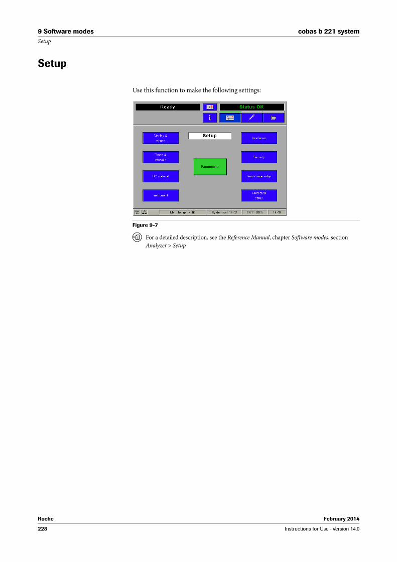
Roche February 2014
228 Instructions for Use · Version 14.0
9 Software modes cobas b 221 systemSetup
Setup
Use this function to make the following settings:
Figure 9-7
U For a detailed description, see the Reference Manual, chapter Software modes, section
Analyzer > Setup

Roche February 2014
Instructions for Use · Version 14.0 229
cobas b 221 system 9 Software modesData manager
Data manager
Use this function to retrieve the following data:
Figure 9-8
U For a detailed description, see the Reference Manual, chapter Softwaremodi, section Data
manager
General data manager functions
Details - all the available detailed information for the selected dataset is displayed and can be edited.
Find - the function allows to search for data records using defined search criteria.
Sort - this function allows to sort the recordings.
Marker - the current data record is permanently marked and now has a yellow background to make it more easily visible.
Mark range - use this function to mark a range.
The marking criterion corresponds to the current sort criterion of the data records.
All data sets are marked only if the "From" input field is empty and "zz" is specified in the "To" field.
Print - the datasets of a marked range or of a marked line are printed out.
Delete - the datasets of the marked range or the marked line are deleted.
"More" - additional available functions are displayed.

Roche February 2014
230 Instructions for Use · Version 14.0
9 Software modes cobas b 221 systemData manager
Q Requirement:
The format must be changed to ASTM.
For calibrations and QC measurements only:
For QC measurements only:
For Backup/Restore only:
Data export to diskette or USB
With this function, the marked data records are exported to a diskette or an USB storage medium.
If it is a device with an SN > 3000, the marked data records are exported to a connected USB storage medium. If no USB storage medium is available, the marked data records are automatically exported to a diskette.
If the USB storage medium is full or write-protected, or if during the read or write process it is disconnected, the error message "Error exporting data" appears.
Repeated transmission of measuring data
Using this function, marked data records of the measurement database are exported again via ASTM to a connected LIS/HIS system.
Filter - to set the required filter.
L.-J. graph - use this function to create a Levey-Jennings graph of the selected datasets from the QC database
QC measurement (Accepted) - using this function the display switches over to the list of the accepted QC measurements.
QC measurement (Rejected) - using this function, the display switches over to the list of rejected QC measurements.
Copy to disk - the marked archive(s) are copied to a disk.
Copy from disk - the archive(s) saved on disk are copied directly back to the archive overview.
Restore archive - the marked dataset(s) are reinserted into the current database.
Backup now - a full databank backup is started.

Roche February 2014
Instructions for Use · Version 14.0 231
cobas b 221 system 9 Software modesData manager
Patients
Patient data that were entered are listed depending on the definition of the display ([Setup] > [Display & reports] > [Patient database] > [Patient database overview]).
Use the buttons "Page up/down" or "Up/down" to select an entry and press the [Details] button. All available information about the selected entry are displayed.
U For a detailed description, see the Reference Manual, chapter Software modes, section
Data manager.
Measurements
Figure 9-9
Measurements that were carried out are listed depending on the definition of the display ([Setup] > [Display & reports] > [Measurement] > [Sample database overview]).
Use the buttons "Page up/down" or "Up/down" to select an entry and press the [Details] button. All available information about the selected entry are displayed.
Q An edit of the specimen ID in the measurement database causes to an automatic delete of all patient relevant information. There is no specimen query started in case of a change of the specimen ID in the database.
In case the patient relevant data is known and needed for patient trending, it is necessary to enter additionally the corresponding patient ID. After the entry of the patient ID the patient demographic query is started automatically.
Because of editing the specimen ID or patient ID, the changed dataset have to be resent to the LIS/HIS manually.
Important:
If the specimen ID is not unique in the LIS, a mismatch of patient related data in the LIS is very likely and it could happen that a measurement is assigned to the wrong patient in the LIS.
Ensure a unique ID in the hospital environment.
U For a detailed description, see the Reference Manual, chapter Software modes, section
Data manager.

Roche February 2014
232 Instructions for Use · Version 14.0
9 Software modes cobas b 221 systemData manager
Calibrations
Figure 9-10
Calibrations that were carried out are listed depending on the definition of the display ([Setup] > [Display & reports] > [Calibration] > [Calibration database overview]).
Use the buttons "Page up/down" or "Up/down" to select an entry and press the [Details] button. All available information about the selected entries are displayed.
QC measurements
Figure 9-11
QC measurements that were carried out are listed depending on the definition of the display ([Setup] > [Display & reports] > [QC measurement] > [QC database overview]).
Use the buttons "Page up/down" or "Up/down" to select an entry and press the [Details] button. All available information about the selected entry are displayed.

Roche February 2014
Instructions for Use · Version 14.0 233
cobas b 221 system 9 Software modesData manager
Instrument
Figure 9-12
Stored instrument data are listed depending on the definition of the display ([Setup] > [Display & reports] > [Instrument database] > [Instrument database overview]).
Use the buttons "Page up/down" or "Up/down" to select an entry and press the [Details] button. All information about the selected entry are displayed.
Utilities
Backup/Restore
Use this function to perform a data backup.
Figure 9-13
U For a detailed description, see the Reference Manual, chapter Software modes, section
Data manager.

Roche February 2014
234 Instructions for Use · Version 14.0
9 Software modes cobas b 221 systemData manager
Protected DB functions
This area is password-protected and only accessible to authorized personnel or customer service.

Roche February 2014
Instructions for Use · Version 14.0 235
cobas b 221 system 9 Software modesInfo
Info
The following information can be displayed:
Figure 9-14
Help
Use this function to retrieve online help information.
Fill level
Figure 9-15
This view lists all the data of the solutions, such as lot number, expiration date, expiration date, start date, the remaining "Time to change" and fill level.

Roche February 2014
236 Instructions for Use · Version 14.0
9 Software modes cobas b 221 systemInfo
QC status
Figure 9-16
Use this function to determine which material/level combination is blocking a parameter.
Press the [Print] button to print out the QC Lock Status report.
Video sequences
Q If this function is not available, contact customer service.
U see Figure 9-14 (p. 235)
List of all activities
Here, all the activities are listed that have to be carried out (including all the maintenance added under Setup > Times & intervals > Maintenance schedule).
Press the button [Print] to print out the list.

Roche February 2014
Instructions for Use · Version 14.0 237
cobas b 221 system 9 Software modesInfo
Figure 9-17
Q All pending maintenance tasks are shown in a rotating display.
Make sure that the tasks displayed on the screen are executed properly and immediately, as any additional pending warnings or information can otherwise not be visualized accordingly.
U See Figure 9-17 (p. 237).
Q Sensor changing:
The sensors must be replaced without delay as soon as the specified time for sensor replacement has been reached. MSS sensors must be replaced no later than after 28 days.
Sensors that remain in the instrument after an alarm will suffer decreased performance, which can result in longer calibration times and deviating measurement values.
The time stated for changing a sensor is a standard value as from the time of insertion of a new sensor or a new electrode. During operation this value is adjusted to the respective state of the sensor/electrode and thus becomes more and more exact.
Q MSS cassette:
The sensors for the parameters glucose, lactate and urea are listed separately in the "List of all activities", but refer to one sensor; these sensors, however, are not changed separately, but together with an MSS cassette.
A Warning window for pending maintenance, rotating display
A

Roche February 2014
238 Instructions for Use · Version 14.0
9 Software modes cobas b 221 systemInfo
List of all warnings
Figure 9-18
Here, all the module stops and warnings are listed with their code, or it can be found in Troubleshooting (p. 291), using the respective error code (ID)
[Action info] Further information is displayed on the errors indicated.
AQC status
Figure 9-19
It shows an overview of the mats and the AutoQC material being used.
Press the [Details] button to display the ampoule status of the selected mat (blue - full, gray - empty).

Roche February 2014
Instructions for Use · Version 14.0 239
cobas b 221 system 9 Software modesInfo
Versions
Figure 9-20
Here, the software versions, the instrument serial number, the MSS cassette label and the date of insertion of the sensors are listed.
Press the button [Print] to print out the list.
Miscellaneous reports
Parameter report
Figure 9-21
Displays the status of the electrodes.

Roche February 2014
240 Instructions for Use · Version 14.0
9 Software modes cobas b 221 systemInfo
Sensor report
Figure 9-22
Displays the current status of the electrodes/sensors.
Press the [Print] button to print out the sensor report.
Status report
Pressing [Print status report] information about the instrument and a multitude of settings will be printed.
Messages
All messages sent by cobas bge link software are displayed here.
The "Message" note is displayed in the error/instruction window of the screen (upper right). This message continues to be displayed as long as there are messages in the message buffer.
Press the [Show message] button to view the entire message.
Press the [Delete message] button to delete the selected message.
Figure 9-23

Roche February 2014
Instructions for Use · Version 14.0 241
cobas b 221 system 9 Software modesInfo
Protected information
This area is password-protected and only accessible to authorized personnel or customer service.

Roche February 2014
242 Instructions for Use · Version 14.0
9 Software modes cobas b 221 systemInfo

February 2014
Maintenance
10 Maintenance................................................................................................................................... 245


Roche February 2014
Instructions for Use · Version 14.0 245
cobas b 221 system 10 MaintenanceTable of contents
Maintenance 10
In this chapter, all maintenance work is described that is necessary for trouble-free operation of the instrument.
In this chapter Chapter 10Maintenance - general ...................................................................................................... 247
Decontamination............................................................................................................... 247
Input unit ..................................................................................................................... 247
Touch Screen................................................................................................................ 248
Surfaces of the instrument ......................................................................................... 248
Tubing paths ................................................................................................................ 248
Recommended disinfectants ..................................................................................... 248
Daily .................................................................................................................................... 249
Checking fill level........................................................................................................ 249
Checking printer paper .............................................................................................. 249
Weekly................................................................................................................................. 250
Cleaning fill port and sample drip tray .................................................................... 250
Cleaning the touch screen.......................................................................................... 250
Quarterly ............................................................................................................................ 252
Cleaning the T&D disk............................................................................................... 252
Changing the air filter ................................................................................................ 253
COOX calibration (for instrument versions with COOX module only)............. 253
Sample-dependent maintenance procedures................................................................. 256
Exchange of solutions and packs............................................................................... 256
S1 Rinse Solution/S2 Fluid Pack/S3 Fluid Pack ................................................ 256
Waste water .................................................................................................................. 259
1. Empty the W Waste Container ....................................................................... 259
2. Using the empty S1 rinse solution bottle as W waste container ................. 261
Installing the waste water container ................................................................... 261
Cleaning the modules and tubing paths................................................................... 262
Module cleaning.................................................................................................... 262
Tubing paths .......................................................................................................... 263

Roche February 2014
246 Instructions for Use · Version 14.0
10 Maintenance cobas b 221 systemTable of contents
Unscheduled ...................................................................................................................... 265
Exchanging the fill port.............................................................................................. 265
Exchanging the peristaltic pump tubes .................................................................... 266
Cleaning the bottle compartment ............................................................................. 268
Replacing printer paper.............................................................................................. 268
Replacement of the electrodes................................................................................... 270
Setting up the Maintenance schedule ....................................................................... 272
Changing the reference electrode ............................................................................. 278
Changing the MSS cassette (cobas b 221<5> system and cobas b 221<6> system only) .............................................................................................................................. 280
Cleaning the measuring chambers ........................................................................... 282
Surfaces......................................................................................................................... 283
Changing of AutoQC mats ........................................................................................ 283
Additional maintenance procedures............................................................................... 286
Yearly service ............................................................................................................... 286
Replacement every three years .................................................................................. 286

Roche February 2014
Instructions for Use · Version 14.0 247
cobas b 221 system 10 MaintenanceMaintenance - general
Maintenance - general
Decontamination
The purpose of this procedure is to minimize the risk of infections when replacing items that were in contact with blood. Perform these decontamination procedures regularly.
Roche recommends following a decontamination procedure in addition to regulations specific to the laboratory.
CAUTION
Caution
r Use only liquid disinfectant such as protein remover (Roche deproteinizer) or an alcohol-based (about 70%) surface disinfectant.
r Do not spray disinfectant directly onto the instrument because this could cause malfunctions in the electronics.
r Do not use any type of bleaching agent. Exception: Roche Deproteinizer
WARNING
Warning
r Do not attempt to decontaminate any part of the instrument before shutting it down and unplugging it from the power source.
r Before plugging the instrument back in and turning it on, always wait 15 minutes to allow the disinfectant to evaporate—Danger of fire and explosion.
r For safety reasons, only authorized technical service personnel may decontaminate the power pack.
Regularly decontaminate the following parts of the instrument:
o Input unit consisting of T&D module (including fill port) and the sample drip tray
o Touch screen
o Surfaces of the instrument
o Tubing paths
Input unit
U see Cleaning fill port and sample drip tray (p. 250)
U see Quarterly (p. 252)
U see Exchanging the fill port (p. 265)
After use, components of the cobas b 221 system, including tubing, waste container, fill port, etc., contain biological fluids and therefore represents a possible infectious risk.
Handle these components with care and according to regulations surrounding potentially infectious materials.
Suitable protective equipment, like laboratory clothing, protective gloves, protective goggles and if necessary mouth protectors, must be worn to prevent direct contact with biological working materials. In addition, a face mask is required if there is a risk. Suitable disinfection and sterilization procedures must be applied.

Roche February 2014
248 Instructions for Use · Version 14.0
10 Maintenance cobas b 221 systemDecontamination
Touch Screen
U see Cleaning the touch screen (p. 250)
Surfaces of the instrument
U see Surfaces (p. 283)
Tubing paths
U see Cleaning the modules and tubing paths (p. 262)
Recommended disinfectants
CAUTION
Caution
r Do not use any type of bleaching agent. Exception: Roche Deproteinizer
Surfaces 70% alcohol surface decontaminant
Tubing paths Protein remover (Roche deproteinizer)
o Potential dangers
Due to the alkaline and oxidizing character of this preparation, we cannot rule out local irritation to the skin, eyes, and mucous membranes.
o First Aid measures
O After inhalation: breath fresh air, drink large amounts of water
O After skin contact: wash with generous amounts of water, remove contaminated clothing
O After eye contact: rinse eyes with generous amounts of water, contact an eye doctor
O After drinking: drink large amounts of water, avoid vomiting, contact a doctor

Roche February 2014
Instructions for Use · Version 14.0 249
cobas b 221 system 10 MaintenanceDaily
Daily
Checking fill level
Press
h Info > Fill level
to check the fill level of the solutions (S1 rinse solution, S2 Fluid Pack, S3 Fluid Pack) and the waste container (W Waste Container) on a daily basis.
Exchange empty bottles, bottles whose usage date has expired, and full waste water bottle.
U see section Exchange of solutions and packs (p. 256) or section Waste water (p. 259).
Checking printer paper
Check daily to be sure that sufficient paper is available and exchange it, if necessary.
Q The printer paper is heat sensitive on one side only. Please make sure that you insert the paper roll correctly.

Roche February 2014
250 Instructions for Use · Version 14.0
10 Maintenance cobas b 221 systemWeekly
Weekly
Cleaning fill port and sample drip tray
P Cleaning fill port and sample drip tray
1 Activate the following function, starting with the top level of the analyzer mode:
h System > Wash & cleaning > Clean input unit
Figure 10-1 Input unit
2 Pull out the sample drip tray and clean it with a cloth moistened with disinfectant.
3 Reinsert the sample drip tray.
4 Clean the fill port with a soft cotton swab moistened with disinfectant.
S
Cleaning the touch screen
P Cleaning the touch screen
1 Activate the following function, starting with the top level of the analyzer mode:
h System > Wash & cleaning > Clean screen
The keys on the screen are deactivated for 30 seconds.
Handle these parts with care — danger of injury. Always wear gloves.
Danger of infection.
A T&D cover C Fill port
B T&D disk D Sample drip tray
B
A
C
D
B

Roche February 2014
Instructions for Use · Version 14.0 251
cobas b 221 system 10 MaintenanceWeekly
CAUTION
Caution
r Clean only with a moist cloth (for example, one that is soaked with disinfectant). Do not use water and sprays.
S

Roche February 2014
252 Instructions for Use · Version 14.0
10 Maintenance cobas b 221 systemQuarterly
Quarterly
Cleaning the T&D disk
P Cleaning the T&D disk
1 Activate the following function, starting with the top level of the analyzer mode:
h System > Wash & cleaning > Clean input unit
2 Pull out the sample drip tray and clean it with a cloth moistened with disinfectant.
U see Figure 10-1 Input unit (p. 250)
3 Remove the T&D cover.
4 Clean the fill port with a soft cotton swab moistened with disinfectant.
5 Rotate the fill port 90° downward and remove it.
Figure 10-2 T&D disk
6 Insert the fill port with the flat side into the slot in the T&D disk and turn it 90 degrees to the right or left. Hold the T&D disk in place during this process.
7 Remove the T&D disk.
8 Clean and decontaminate the front and back of the T&D disk.
CAUTION
Caution
r Do not use alcohol for cleaning the T&D disk.
9 Re-install the disk in reverse order.
10 Re-insert the fill port.
11 Close the T&D cover.
12 Insert the sample drip tray.
S
A Needle
A

Roche February 2014
Instructions for Use · Version 14.0 253
cobas b 221 system 10 MaintenanceQuarterly
Changing the air filter
P Changing the air filter
1 Pull out the air filter using the box tongue (see below).
Figure 10-3 Air filter
2 Dispose of the air filter according to local regulations (hazardous waste)
3 Push in the new air filter according to the figure.
U see Figure 10-3 Air filter (p. 253)
Q The exchange may be performed less frequently in clean lab operations and at room temperature (significantly below the maximum permissible operating temperature).
S
COOX calibration (for instrument versions with COOX module only)
Q This calibration must always be performed following a manipulation of the cuvette, but not later than every 3 months.
To calibrate the COOX module, enter the tHb calibrator or a blood sample whose tHb values are exactly known.
P Performing a COOX calibration
1 Take the ampoule out of the package.
2 Carefully shake the ampoule.
3 Gently tap the head of the ampoule with your fingernail to remove any liquid from the top.
4 Break open the ampoule. Completely insert the ampoule adapter into the ampoule or fill the sample into a capillary.
5 Activate the following function, starting with the top level of the analyzer mode:
h System > Calibration > COOX calibration
To avoid injury, protect your hands with gloves and tissues when breaking open the ampoule.
Never reuse the ampoule and the capillary.

Roche February 2014
254 Instructions for Use · Version 14.0
10 Maintenance cobas b 221 systemQuarterly
6 To start the calibration, press [Start].
The following screen appears:
Figure 10-4
7 "tHb (target value) [g/dL]": enter the desired target value using the keyboard.
Q Take the target value for the tHb calibrator from the label of the tHb calibrator recommended by Roche.
8 The unit is standard [g/dL] and can be changed, if necessary.
9 "Cuvette replaced" - Press [Yes] after a cuvette was replaced, otherwise press [No].
10 "Sample type". It is possible to select between "tHb calibrator" and "Blood" as calibration solution.
11 The target value for blood must be a known set point.
12 Attach the ampoule adapter (see below/A) or the capillary (see below/B) filled with tHb calibrator to the fill port (follow the instructions on the screen).
Figure 10-5 Ampoule adapter/Capillary
The COOX calibration is carried out.
After the measurement, the result is displayed. In ideal circumstances, the tHb(i) value should be identical with the tHb(m) measurement.
A Ampoule adapter B Capillary

Roche February 2014
Instructions for Use · Version 14.0 255
cobas b 221 system 10 MaintenanceQuarterly
WARNING
Warning
r If the cuvette has been replaced, no calibration value appears, just the comment "COOX calibration performed". In event of error, repeat the COOX calibration.
This function allows for the introduction of tightened "limits" in your own estimation. In general, values in the range of +/- 20% of the set point can be accepted in accordance with the adjustability of the module.
If the calibration values are not acceptable, press [Reject]. The module is not calibrated and transferred to an alarm state.
A recalibration should be performed.
By pressing [Accept], the calibration values are accepted and used for calculating the layer thickness of the cuvette.
If the calculated thickness layer and the corresponding reference value do not fall within the specified internal limits, the COOX module is failed and the calibration needs to be repeated.
S

Roche February 2014
256 Instructions for Use · Version 14.0
10 Maintenance cobas b 221 systemSample-dependent maintenance procedures
Sample-dependent maintenance procedures
Exchange of solutions and packs
WARNING
Warning
r In order to ensure the quality of the measurement results, complete a quality control test on 3 levels (1 = low, 2 = normal, 3 = high) after each exchange of solutions.
These solutions should be exchanged depending on the rate of measurement and/or the onboard stability. The screen displays the appropriate information.
Figure 10-6 Solutions and packs
S1 Rinse Solution/S2 Fluid Pack/S3 Fluid Pack
Depending on the rate of measurement and/or the onboard stability, this fluid packs should be exchanged every 6 weeks. The screen displays the appropriate information.
WARNING
Warning
r The use of an expired fluid pack can lead to calibration errors.
r Insert a new pack which has not expired.
r Never use expired bottles/packs.
A Rubber sealings B cobas b 221<5> system and cobas b 221<6> system only
AA
B

Roche February 2014
Instructions for Use · Version 14.0 257
cobas b 221 system 10 MaintenanceSample-dependent maintenance procedures
P Procedure starting from the analyzer mode:
1 Open the bottle compartment cover.
The following screen appears:
Figure 10-7
2 Open the docking mechanism and pull out the bottles/packs to be exchanged.
WARNING
Warning
r Remove packs’ rubber sealings.
3 Insert the new bottle or the new pack in the corresponding position until it stops.
4 The cobas b 221 system recognizes the correct bottle or the correct packs and verifies the expiration date.
5 If the bottle has passed the expiration date, the screen displays a warning.
6 Close the docking mechanism and the bottle compartment cover. The solutions are automatically aspirated upwards (detection in the flap).
7 A new QC measurement with all three level (1 = low, 2 = normal, 3 = high) must be performed after every exchange of solutions and packs.
8 Make sure that the results are in line with the target values.
U see Quality control (p. 173)
Q To prevent spilling of the S1 rinse solution:
If your facility is 3000 m above sea level or higher deaerate the bottle before inserting to avoid splashing the S1 rinse solution.
S
A cobas b 221<5> system and cobas b 221<6> system only
A
Dispose of the bottles/packs according to local regulations (hazardous waste).

Roche February 2014
258 Instructions for Use · Version 14.0
10 Maintenance cobas b 221 systemSample-dependent maintenance procedures
P Procedure
1 Place the bottle tool (see below/A) on the screw cap of the S1 rinse solution (see below/B).
Figure 10-8 Bottle tool
2 Press the grips together and press the transparent disk downward (see below/A).
3 Rotate the transparent disk clockwise and stop when you notice a resistance after a short distance (see below/B).
Figure 10-9 Deaerate bottle S1
S
A Bottle tool B Bottle tool on the screw cap
A B

Roche February 2014
Instructions for Use · Version 14.0 259
cobas b 221 system 10 MaintenanceSample-dependent maintenance procedures
Waste water
P Exchange the waste water container (W Waste Container)
1 Open the bottle compartment cover.
The bottle exchange image appears on the display.
Figure 10-10
2 Open the docking mechanism, hold the waste water bottle by the grip recesses and remove carefully.
S
1. Empty the W Waste Container
Always wear gloves. Danger of infection.
Dispose of the waste water container according to local regulations (hazardous waste).
Always wear gloves. Danger of infection.

Roche February 2014
260 Instructions for Use · Version 14.0
10 Maintenance cobas b 221 systemSample-dependent maintenance procedures
P Emptying the W Waste Container
1 Place the bottle tool on the screw cap.
Figure 10-11 Bottle tool
2 Open the screw cap by pressing the two grips together and rotate them counter-clockwise.
Figure 10-12 Open the screw cap
3 When removing the screw cap, make sure that the green element inside the container is not moved or removed.
Figure 10-13 Screw cap
4 Screw the cap back onto the container. The cap must be screwed shut until completely closed.
S
A Bottle tool B Screw cap with placed bottle tool
Empty the waste water and decontaminate the container according to local regulations (hazardous waste).
Flush the waste water bottle cap with plenty of water.
Replace waste water container and the screw cap after approximately 5 uses.
Dispose of the waste water container according to applicable local codes and regulations (hazardous waste).

Roche February 2014
Instructions for Use · Version 14.0 261
cobas b 221 system 10 MaintenanceSample-dependent maintenance procedures
2. Using the empty S1 rinse solution bottle as W waste container
o Remove the sticker from the empty bottle of S1 rinse solution.
Q This sticker may not be reused – discard immediately.
Figure 10-14 Sticker
Installing the waste water container
P Installing the waste water container
1 Push the bottle to the position for waste water W until it engages.
2 Close the docking mechanism.
3 The fill level monitoring feature recognizes the waste container as "Empty".
If the waste water container to be used is not empty: Press [Waste fill level] and enter the fill level (a scaling on the container label gives an approximate value).
4 Close the bottle compartment cover.
S
A Remove the S1 sticker from the bottle at this location.
B Pull off the sticker beginning from the lower right corner (arrow) until the sticker "Waste" is completely visible
D W" sticker on the bottle of S1
C "W" sticker
D
B CA

Roche February 2014
262 Instructions for Use · Version 14.0
10 Maintenance cobas b 221 systemSample-dependent maintenance procedures
Cleaning the modules and tubing paths
Module cleaning
If required, an internal cleaning procedure is automatically carried out during the 2P calibration and a system calibration (which similarly includes a 2P calibration).
The instrument is delivered with the following standard settings for automatic internal cleaning:
Automatic BG cleaning If the automatic BG cleaning is activated, internal instrument data such as the measuring frequency and drift behavior of the sensors is used to automatically select an optimum cleaning interval.
U see Reference Manual chapter 3 Setup, section Times & intervals > Maintenance schedule.
External cleaning An additional external cleaning with deproteinizer should only be carried out if the measuring chamber is contaminated (protein deposits) or if components of the sample path must be exchanged.
Activate the following function, starting with the top level of the analyzer mode:
h System > Wash & cleaning > Cleaning modules
Figure 10-15
Measuring module Samples Cycle
BG 500 never
ISE 200 never
COOX und tHb/SO2 20 never
MSS --- never
Table 10-1

Roche February 2014
Instructions for Use · Version 14.0 263
cobas b 221 system 10 MaintenanceSample-dependent maintenance procedures
P BG-/ISE-/ COOX- or tHb/SO2 module:
Q ISE module: the frequency of the cleaning process depends on the lab-specific type of sample (physiological, pathological, fetal blood).
BG module: should be cleaned only on demand, in the following scenario:
o visible blood clot in the BG module
o low PO2 QC recoveries due to microscopic bacterial contamination of the PO2 electrode
1 Activate the corresponding module and press [Start external cleaning].
2 The external cleaning agent is inserted like a sample (syringe or capillary) via the fill port.
3 Each external cleaning must be followed by a wetting using whole blood or serum, press:
h System > Utilities > Fluid actions > Wetting routines
4 Pressing [Start internal cleaning] to carry out a cleaning using the internal cleaning solution.
S
P MSS module (cobas b 221<5> system and cobas b 221<6> system only):
1 This cleaning should be performed with every exchange of the cassette, but not more than once per month (e.g. obstruction).
2 Activate the MSS module and press [Start external cleaning].
3 The external cleaning agent is inserted like a sample (syringe or capillary) via the fill port.
4 Insert a new MSS cassette using the correct procedure.
U see Changing the MSS cassette (cobas b 221<5> system and cobas b 221<6> system
only) (p. 280)
After the cleaning, perform a polarization of the new MSS cassette.
S
Tubing paths
Using the function Decontamination all the tubing paths in the instrument can be decontaminated.
WARNING
Warning
r In order to ensure the quality of the measurement results, complete a quality control test on 3 levels (1 = low, 2 = normal, 3 = high) after the decontamination routine.
h System > Wash & cleaning > Decontamination
This decontamination is carried out in a similar way to the shut down routine, except that deproteinizer is used instead of distilled water.
The shutdown kit is required for carrying out this function.

Roche February 2014
264 Instructions for Use · Version 14.0
10 Maintenance cobas b 221 systemSample-dependent maintenance procedures
Q The decontamination procedure must be carried out completely and may not be interrupted.
Observe the listed sequence while performing the actions.
Processing the actions:
Manual The corresponding line of the list box contains an instruction which must be performed manually. Then press [Confirm action].
Automatic If there is an automatic sequence for any action, you can start this by clicking [Start process].
If an action has been completed successfully (manually or automatically), this symbol is displayed.

Roche February 2014
Instructions for Use · Version 14.0 265
cobas b 221 system 10 MaintenanceUnscheduled
Unscheduled
Exchanging the fill port
P Exchanging the fill port
1 Activate the following function, starting with the top level of the analyzer mode:
h System > Wash & cleaning > Clean input unit
2 Pull out the sample drip tray and clean it with a cloth moistened with disinfectant.
3 Open the T&D cover.
4 Rotate fill port 90° downward and carefully remove it from the needle.
Figure 10-16
5 Insert new fill port.
CAUTION
Caution
r Do not bend the needle.
6 Close the T&D cover.
7 Reinsert the sample drip tray.
8 Close the bottle compartment cover.
S
Dispose of the used fill port in accordance with local regulations (hazardous waste).
A Needle
A

Roche February 2014
266 Instructions for Use · Version 14.0
10 Maintenance cobas b 221 systemUnscheduled
Exchanging the peristaltic pump tubes
P Exchanging the peristaltic pump tubes
1 When changing the peristaltic pump tubes, proceed as follows:
Activate the following function, starting with the top level of the analyzer mode:
h Quick access > Maintenance
Figure 10-17 Peristaltic pump
2 Select the appropriate pump tube to be changed from the list and press [Perform].
3 Remove the top cover.
4 Open the peristaltic pump's clear plastic cover (tension lever) (see below/A).
Figure 10-18 Peristaltic pump
5 Push the linear bracket (white plastic part) upwards (see below/A).
A Main pump C MSS input pump
B MSS output pump
A Tension lever
B Pump head
C Linear bracket
A B C
A
B
C

Roche February 2014
Instructions for Use · Version 14.0 267
cobas b 221 system 10 MaintenanceUnscheduled
6 Remove the complete tubing set (tubing holder and tubing) of the corresponding pump (see below/B).
Figure 10-19 Peristaltic pump
7 Check if the five rollers are easily moveable.
In case of malfunction contact customer service.
8 Place the tube around the corresponding rolling wheel. Check that the tubing set is correctly orientated (the grip end must be pointing upwards, see above/B).
9 Close the clear plastic cover (tension lever). The tubing holder is then pressed into the sealer.
10 Close the top cover.
Q The peristaltic pump tubes are also replaced during the annual service.
U see section Additional maintenance procedures (p. 286)
S
A Move linear bracket upwards B Remove tubing set
The tubes may drip a little after being disconnected.
Remove excess fluids with a clean, absorbent cloth.

Roche February 2014
268 Instructions for Use · Version 14.0
10 Maintenance cobas b 221 systemUnscheduled
Cleaning the bottle compartment
P Cleaning the bottle compartment
1 Open the bottle compartment cover.
The bottle exchange image appears on the display.
Figure 10-20
2 Open the docking mechanism and pull out all the bottles or packs.
3 Clean the bottle compartment with a cloth moistened with disinfectant (e.g. disinfectant containing 70% alcohol).
4 Reinsert the bottle or packs.
U see Exchange of solutions and packs (p. 256)
5 Close the docking mechanism and the bottle compartment cover.
S
Replacing printer paper
P Replacing the printer paper
1 Open the printer cover.
Q The printer paper is heat sensitive on one side only. Observe the correct insertion of the thermal paper roll.
2 Open the paper lid.
3 Remove the empty paper roll.
4 Ensure the paper has a clean leading edge to help start the paper through the rollers. If necessary cut the paper at a right angle.
5 Place the new paper roll into the holder, so that the roll feeds from the bottom.

Roche February 2014
Instructions for Use · Version 14.0 269
cobas b 221 system 10 MaintenanceUnscheduled
6 Ensure that the printer lever is in the "down" position (see below) (only visible with opened paper cover).
Figure 10-21 Printer lever
7 Feed in the beginning of the paper according to the instructions on the inside of the paper lid (see below).
Figure 10-22 Place printer paper- without take-up unit
Figure 10-23 Place printer paper - with take-up unit (optional)
8 The paper is automatically pulled into the printer.
If the paper is pulled in incorrectly, open the paper cover, open the printer lever and realign the paper, close the printer lever and close the paper lid again.
9 Close paper lid.
S
P With take-up unit (optional)
1 Press the paper feed button until the paper is long enough.
2 Insert the beginning of the paper in the take-up unit according to the instructions on the inside of the paper lid.
U see Figure 10-23 Place printer paper - with take-up unit (optional) (p. 269)
A Paper lid B Printer lever
A
B

Roche February 2014
270 Instructions for Use · Version 14.0
10 Maintenance cobas b 221 systemUnscheduled
Q Press the take-up unit (rods) fully onto the holder and rotate until the paper is taut on the rods and paper lid, so that the entire roll of paper can be taken up. During operation, the paper should be tautened now and then by turning the take-up roller.
3 Close printer cover.
CAUTION
Caution
r With an installed take-up unit, the "Automatic Cut" function is deactivated.
S
Replacement of the electrodes
P Replacing of the electrodes
1 Remove the top cover and open the measuring chamber cover of the corresponding measurement module (apply force to push the right edge of the MC cover to the left with a finger and open up the MC cover).
WARNING
Warning
r The electrode must be installed in the instrument no later than the imprinted "Install before" date.
U see Conventions used in this manual (p. 7) > Other symbols (p. 10)
r In order to ensure the quality of the measurement results, complete a quality control test on 3 levels (1 = low, 2 = normal, 3 = high) after each electrode exchange.
Q In each case, open only the relevant measuring chamber. Keep the bottle compartment cover closed.
The following screen appears:
Figure 10-24
2 Open the locking lever.
3 Take the appropriate electrode, move it to the left and remove it.
Dispose the electrode(s) according to local regulations (hazardous waste).

Roche February 2014
Instructions for Use · Version 14.0 271
cobas b 221 system 10 MaintenanceUnscheduled
4 If necessary, clean the measuring chamber with a cloth moistened with disinfectant (e.g. disinfectant containing 70% alcohol).
Q If a new electrode is not available, insert a dummy electrode instead.
SCon and the reference electrode may not be replaced with a dummy electrode.
CAUTION
Caution
r If an electrode is replaced by a dummy electrode, it must be immediately deactivated permanently for measurements and calibrations under [Setup] > [Parameters] > [Miscellaneous settings]. To do so, deactivate the switch [Activated for calibrations].
5 Check the internal electrolyte of the electrodes for possible air bubbles (see below/A).
6 Remove any air bubbles. Hold the electrode vertically and tap lightly with a fingernail against the electrode body (see below/B).
Figure 10-25 Electrode
7 Insert the new electrode according to the color code.
8 Push all electrodes slightly to the right so that they are lined up together without gaps.
9 Close the locking lever.
10 Scan the barcodes located on the inner packaging of each electrode or enter the barcodes manually with the help of the keyboard.
11 The replaced electrode is shown slightly lower than the others displayed on the screen.
A Free of air bubbles B Remove air bubbles
B
A

Roche February 2014
272 Instructions for Use · Version 14.0
10 Maintenance cobas b 221 systemUnscheduled
12 Read the next actions, their duration and the sensor data.
Figure 10-26
13 Close the measuring chamber and then the top cover.
14 A calibration is performed following a warm-up phase.
15 After completing the calibration, perform a quality control measurement on all 3 level (1 = low, 2 = normal, 3 = high).
16 Make sure that the results are in line with the target values.
U see Quality control (p. 173)
S
Setting up the Maintenance schedule
The Maintenance schedule is used to alert users when the reference electrode or other electrodes, e.g. ISE, and MSS (Urea) must be replaced.
WARNING
Warning
r The reference electrode must be replaced after 52 weeks of in-use time.

Roche February 2014
Instructions for Use · Version 14.0 273
cobas b 221 system 10 MaintenanceUnscheduled
P Set up a new Maintenance schedule
1 Press the following buttons:
h Setup > Times & interval > Maintenance schedule
Figure 10-27 Maintenance schedule
2 Choose the New button.
Figure 10-28 New schedule

Roche February 2014
274 Instructions for Use · Version 14.0
10 Maintenance cobas b 221 systemUnscheduled
3 Fill out the schedule fields using the button. The reference electrode has an in-use time of 52 weeks. For the Interval field, select one year.
Figure 10-29 Fill out the schedule fields
4 Choose the button to save the setup.
5 Confirm schedule setup.
Figure 10-30 Confirm schedule setup
Q Note
Use the Maintenance schedule to set up an alert for the ISE and MSS (Urea) reference electrodes.
S

Roche February 2014
Instructions for Use · Version 14.0 275
cobas b 221 system 10 MaintenanceUnscheduled
P Edit an existing Maintenance schedule
1 Press the following buttons:
h Setup > Times & interval > Maintenance schedule
Figure 10-31 Maintenance schedule
2 Select the schedule for editing and choose the Edit button.
Figure 10-32 Select schedule

Roche February 2014
276 Instructions for Use · Version 14.0
10 Maintenance cobas b 221 systemUnscheduled
3 Edit the schedule fields using the button. The reference electrode has an in-use time of 52 weeks. For the Interval field, select one year.
Figure 10-33 Edit schedule fields
4 Choose the button to save the setup.
5 Confirm the schedule setup.
Figure 10-34 Confirm schedule setup
S

Roche February 2014
Instructions for Use · Version 14.0 277
cobas b 221 system 10 MaintenanceUnscheduled
P Delete a Maintenance schedule
1 Press the following buttons:
h Setup > Times & interval > Maintenance schedule
Figure 10-35 Maintenance schedule
2 Select the schedule for deletion and choose the Delete button.
Figure 10-36 Select schedule

Roche February 2014
278 Instructions for Use · Version 14.0
10 Maintenance cobas b 221 systemUnscheduled
3 Confirm the schedule has been deleted.
Figure 10-37 Confirm schedule deletion
S
Changing the reference electrode
P Changing the reference electrode
1 Remove the top cover and open the measuring chamber cover.
WARNING
Warning
r The reference electrode must be installed in the instrument no later than the imprinted "Install before" date. The reference electrode must be replaced after 52 weeks of in-use time. Therefore, set up an alert in the Maintenance schedule.
U see Setting up the Maintenance schedule (p. 272)
U see Conventions used in this manual (p. 7) > Other symbols (p. 10)
r In order to ensure the quality of the measurement results, complete a quality control test on 3 levels (1 = low, 2 = normal, 3 = high) after each electrode exchange.
Figure 10-38 Reference electrode
Q In each case, open only the relevant measuring chamber.
Keep the bottle compartment cover closed.
The following screen appears:

Roche February 2014
Instructions for Use · Version 14.0 279
cobas b 221 system 10 MaintenanceUnscheduled
Figure 10-39
2 Open the locking lever.
3 Remove the reference electrode.
4 Remove the white connector from the measuring chamber cartridge.
5 Insert the new reference electrode.
6 Attach the white connector at the end of the tube to the measuring chamber cartridge.
7 Insert the reference tube into the upper tube guide channel of the left locking lever and into the tube holder of the cover hinge. Close the locking lever.
Figure 10-40 Insert the reference electrode
8 Connect the white connector on the end of the tube to the measuring chamber cassette (see below).
Figure 10-41 Insert the reference electrode 2
A Locking lever
A Connector B Measuring chamber cassette
A
B
A

Roche February 2014
280 Instructions for Use · Version 14.0
10 Maintenance cobas b 221 systemUnscheduled
9 Scan the barcode of the exchanged reference electrode located on the inner packaging or enter the barcodes manually with the help of the keyboard.
10 Close the measuring chamber and top cover.
11 A conductivity calibration is performed following a warm-up phase.
12 A new QC measurement with all three levels (1 = low, 2 = normal, 3 = high) must be performed after every exchange of a reference electrode.
Make sure that the results are in line with the target values.
U see Quality control (p. 173)
S
Changing the MSS cassette (cobas b 221<5> system and cobas b 221<6> system only)
P Changing the MSS cassette
1 Remove the top cover.
WARNING
Warning
r The MSS cassette must be installed in the instrument no later than the imprinted "Install before" date.
U see Conventions used in this manual (p. 7) > Other symbols (p. 10)
r Replace the MSS cassette within 28 days of installation.
r In order to ensure the quality of the measurement results, complete a quality control test on 3 levels (1 = low, 2 = normal, 3 = high) after each MSS cassette exchange.
Q Hold the MSS cassette only at the designated handle and avoid touching the contacts.
2 Open the cover of the MSS module (apply force to the right edge of the MC cover with a finger to push it to the left and open up the MC cover).
Q Keep the bottle compartment cover closed.
The following screen appears:
Before exchanging the MSS cassette, it is absolutely necessary to prepare a syringe or capillary with whole blood for polarization.
The blood should have a volume of at least 150 μL, contain heparin as an anticoagulant, and be stored for less than 24 hours.

Roche February 2014
Instructions for Use · Version 14.0 281
cobas b 221 system 10 MaintenanceUnscheduled
Figure 10-42
3 Open the contact clip and the locking lever.
4 Push the reference contact (RCon) (see below/B) or the MSS reference electrode (Ref+ Dummy) (see below/A) and the MSS cassette slightly to the left in the direction of the arrow and remove the MSS cassette.
Figure 10-43 MSS measuring chamber
5 Insert the new MSS cassette, and close the locking lever and the contact clip.
6 Read in the barcode from the packaging of the MSS cassette.
7 Close the measuring chamber and top cover.
8 Follow the instructions on the screen. The prepared blood sample is inserted into the fill port similar to a measurement
U see Measurement (p. 143)
9 The MSS cassette is subsequently exposed to liquid, polarized, heated and calibrated.
A Glu/Lac/Urea C Locking lever
B Glu or Glu/Lac D Contact clip
D
C
BA

Roche February 2014
282 Instructions for Use · Version 14.0
10 Maintenance cobas b 221 systemUnscheduled
10 If the automatic polarization was not successful and the MSS parameters are not calibrated, a manual polarization must be performed.
11 Activate the following function, starting with the top level of the analyzer mode:
h System > Utilities > MSS polarization
Figure 10-44
12 Follow the instructions on the screen.
13 A new QC measurement must be performed with all three level (1 = low, 2 = normal, 3 = high) after every exchange of the MSS cassette.
Make sure that the results are in line with the target values.
U see Quality control (p. 173)
S
Cleaning the measuring chambers
P Cleaning the measuring chambers
1 Remove the top cover and open the measuring chamber cover.
2 Remove all electrodes.
U see Replacement of the electrodes (p. 270)
3 Clean the measuring chamber with a cloth moistened with disinfectant (e.g. disinfectant containing 70% alcohol).
4 Reinsert the electrodes.
5 Close the measuring chamber cover and top cover.
Q Do not scan a barcode. Instead, perform the following calibrations:
BG, ISE: calibrating the mixing system, 2P calibration
MSS: system calibration
U see section User-activated calibrations (p. 214)
S

Roche February 2014
Instructions for Use · Version 14.0 283
cobas b 221 system 10 MaintenanceUnscheduled
Surfaces
WARNING
Warning
r Do not attempt to decontaminate any part of the instrument before shutting it down and unplugging it from the power source.
r Before plugging the instrument back in and turning it on, always wait 15 minutes to allow the disinfectant to evaporate — Danger of fire and explosion.
r For safety reasons, only authorized customer service personnel may decontaminate the power pack.
Regularly decontaminate all outer surfaces of the instrument, including all covers (e.g. printer cover, bottle compartment cover, top cover, T&D cover), with the disinfectant according to the lab-specific regulations.
Very dirty surfaces should first be cleaned with a swab or paper towel that has been soaked in distilled water. All removable covers (e.g. instrument cover) can be removed, sprayed with surface disinfectant and subsequently disinfected using swabs or cellulose.
Some surfaces require extended soaking to achieve cleaning.
WARNING
Warning
r Never spray parts that cannot be removed or that are inside the instrument.
U see section Decontamination (p. 247)
Changing of AutoQC mats
P Changing of AutoQC mats
1 Starting with the top level of the analyzer mode.
2 Pull out the AutoQC drawer.
The following screen appears:
Figure 10-45

Roche February 2014
284 Instructions for Use · Version 14.0
10 Maintenance cobas b 221 systemUnscheduled
3 Remove the empty mat from the ampoule holder.
4 Take a full mat (20 ampoules) from the package.
5 Turn the mat so that the necks of the ampoules face down. Gently wave but do not shake the mat and ensure that the necks of the ampoules are free of air bubbles.
Figure 10-46 AutoQC mat
6 Place the mat in the defined position (A-F) of the ampoule block so that the ampoules are no longer visible.
7 Press [Refill].
The following question appears:
Figure 10-47
8 Press [Yes] – if the mat is replaced with a new one of the same lot. The number of the ampoules is set to 20.
Q Press [No] - if the new mat was not inserted from the same batch.
In this case the material has to be newly defined.
U See section Material setup (p. 179)
If individual ampoules remain in the white ampoule holder after removing the mats, note that these open ampoules may break on removal with the attendant risk of injury. Before inserting a new mat remove them all carefully.
Always wear gloves.
If ampoules have expired as specified in the insert sheet, dispose of mats in accordance with local regulations.
Caution: danger of spilling.

Roche February 2014
Instructions for Use · Version 14.0 285
cobas b 221 system 10 MaintenanceUnscheduled
9 In case the mats are not completely filled press [Details]. By pressing the corresponding key the status of the selected ampoule can be changed (see below) and/or the ampoules to be measured can be selected.
This function can also be used when full ampoules are removed from the mat for manual measurement.
Figure 10-48
10 Close the AutoQC drawer.
S

Roche February 2014
286 Instructions for Use · Version 14.0
10 Maintenance cobas b 221 systemAdditional maintenance procedures
Additional maintenance procedures
CAUTION
Caution
r The listed maintenance procedures may only be performed by the Technical Support or by Roche authorized personnel.
r The components have been tested during development of the instrument to identify worn parts. They must be replaced at the annual service to prevent potential malfunctions.
Yearly service
In the course of the yearly service the following components have to be replaced:
cobas b 221<1>-<6> system:
o Sample tube
o Fill port
o T&D tubing set
o PP pump head
o PP pump tube
o FMS tubing set
o Waste separator
o Bypass nipple
o Bacteria filter
o T&D disk
o Tubing set tHb/COOX
cobas b 221<2>/<4>/<6> system only:
o Cuvette
o Cuvette seals
o Hemolyzer tube
WARNING
Warning
r The tubing paths must also be disinfected annually and the baro value must be checked.
Replacement every three years
Every three years the following components have to be replaced:
cobas b 221<1>-<6> system:
o Sample tube
o Fill port
o T&D tubing set
o PP pump head
o PP pump tube
o FMS tubing set
Roche February 2014
Instructions for Use · Version 14.0 287
cobas b 221 system 10 MaintenanceAdditional maintenance procedures
o Waste separator
o Bypass nipple
o Bacteria filter
o T&D disk
o Tubing set tHb/COOX
o Sample distributor cartridge
o Measuring chamber cartridge
o Hb cartridge
o Waste tubing
o VP tubing set
cobas b 221<2>/<4>/<6> system only:
o Cuvette
o Cuvette seals
o Hemolyzer tube
WARNING
Warning
r The tubing paths must also be disinfected annually and the baro value must be checked.

Roche February 2014
288 Instructions for Use · Version 14.0
10 Maintenance cobas b 221 systemAdditional maintenance procedures

February 2014
Troubleshooting
11 Troubleshooting .............................................................................................................................. 291


Roche February 2014
Instructions for Use · Version 14.0 291
cobas b 221 system 11 TroubleshootingTable of contents
Troubleshooting 11
In this chapter, all fault messages, their causes and remedies are described. These are also displayed directly on the instrument screen. All messages are arranged according to info number.
In this chapter Chapter 11Troubleshooting - general ................................................................................................ 293
System stops ....................................................................................................................... 294
Emergency routine...................................................................................................... 294
Module stops...................................................................................................................... 300
System warnings ................................................................................................................ 304
Status messages of measuring and calibration values................................................... 308
Status messages on the measurement report ................................................................. 324
Barcode ............................................................................................................................... 325

Roche February 2014
292 Instructions for Use · Version 14.0
11 Troubleshooting cobas b 221 systemTable of contents

Roche February 2014
Instructions for Use · Version 14.0 293
cobas b 221 system 11 TroubleshootingTroubleshooting - general
Troubleshooting - general
The cobas b 221 system can monitor for air bubbles, clots, leaks, and blockages in the system. Should the instrument detect any of these problems, an error message will occur in the form of a system stop, module stop, or status message depending on the issue.
Depending on the error, the font in the error/message window changes color:
o System stop: to red
o Module stop: to yellow
o System warnings and status messages: to white
For all system stops, module stops and status messages for measurement and calibration values, a fault analysis and removal suggestions appear directly on the screen.
After use, components of the cobas b 221 system, including tubing, waste container, fill port, etc., contain biological fluids and represent therefore a possible infectious risk.
Handle these components with care and according to regulations surrounding potentially infectious materials.
Suitable protective equipment, like laboratory clothing, protective gloves, protective goggles and if necessary mouth protectors, must be worn to prevent direct contact with biological working materials. In addition, a face mask is required if there is a risk of splashes. Suitable disinfection and sterilization procedures must be applied.

Roche February 2014
294 Instructions for Use · Version 14.0
11 Troubleshooting cobas b 221 systemSystem stops
System stops
This error creates a window outlined in red halting the analyzer. An error message in red is also displayed in the error window (upper right hand corner) on the display screen. The error window will remain until corrective action is taken.
Follow the instructions on the screen.
Emergency routine
In case of a system stop, the emergency routine will initially be started after 50 minutes and then every 4 hours to prevent crystallizations in tubings, pipes and electrodes. This routine cannot be interrupted. In the process Mix1 is positioned into the BG and the ISE measuring chamber and MSS standby solution is positioned into the MSS measuring chamber.
Resolve all system stops:
h Info > List of all warnings
No. Message Cause Action
10001 Flap W Docking mechanism for waste is open.
o Close mechanism.
If the error persists, contact Technical Support.
10002 Out of operation The instrument has been taken out of operation.
o Perform installation procedure.
U see section Installation (p. 45)
10003 Warm up The instrument warms up after power-on or power fail.
o Wait until the warm up is finished and perform installation procedures if necessary.
U see section Installation (p. 45)
10004 Economy mode The instrument is in automatic or manual economy mode.
o To return to the "ready" mode press Exit.
10005 Comm. error PC-μC Communications between PC and micro controller is interrupted.
o Turn the instrument off and on again.
If the error persists, contact Technical Support.
10006 Download error The download process to the micro controller failed.
o Turn the instrument off, wait at least 3 minutes, and turn it back on.
If the error persists, contact Technical Support.
10008 No waste container Waste container is missing. o Insert container.
If the error persists, contact Technical Support.
10009 Actuator bus current overload
An error was recognized in a hardware component.
o Perform General hardware test to correct the error: h System > Diagnostics > General hardware test
If the error persists, turn the instrument off and contact Technical Support.
10010 Valve bus current overload
An error was recognized in a hardware component.
o Perform General hardware test to correct the error: h System > Diagnostics > General hardware test
If the error persists, turn the instrument off and contact Technical Support.
10011 Database not ready The database is not ready. o Wait some minutes if the error occurs during warm up.
o Turn the instrument off, wait at least 3 minutes, and turn it back on.
If the error persists, contact Technical Support.
Table 11-1 System stops

Roche February 2014
Instructions for Use · Version 14.0 295
cobas b 221 system 11 TroubleshootingSystem stops
10012 μC memory overrun A micro controller memory overflow was detected
o Turn the instrument off, wait at least 3 minutes, and turn it back on.
If the error persists, contact Technical Support.
10016 Bottle compartment cover open
o Close the bottle compartment cover.
If the error persists, contact Technical Support.
10017 Bypass wash error 1 Sample sensor SS2 detects not enough air during wash process.
o Perform Wash again: h System > Wash & Cleaning > Washif necessary replace the T&D tubing set
If the error persists, contact Technical Support (wash-water jet is plugged).
10018 SD wash error 1 Sample sensor SS2 detects not enough air during wash process.
o Perform Wash again: h System > Wash & Cleaning > Washif necessary replace the T&D tubing set
If the error persists, contact Technical Support (wash-water jet is plugged).
10019 Waste container full o Insert an empty waste water bottle or enter the correct fill info for the waste water bottle currently in use. To do so, open the docking mechanism for W briefly, then close it again. The "Enter fill info" button appears on the screen.
10020 Rinse bottle empty The transponder on the S1 Rinse Solution bottle indicates an empty bottle
o Insert new S1 Rinse Solution.
U see section Exchange of solutions and packs (p. 256).
10021 Flap S1 Docking mechanism for S1 Rinse Solution is open.
o Close mechanism
10022 μC Reset o Turn the instrument off, wait at least 3 minutes, and turn it back on.
If the error persists, contact Technical Support.
10023 Power fail A power fail occurred. o The instrument will be ready for operation after warm up.
10024 No wash-water container o Insert S1 Rinse Solution
10025 Check date and time o Check date and time in the "Setup" mode and perform any necessary changes:h Setup > Times & intervals > Act. time date
10026 Bypass wash error 2 Sample sensor SS2 detects insufficient water during wash process.
o Perform Wash again: h System > Wash & Cleaning > Washif necessary check the fill port area for any dirt or clogging.
If the error persists, contact Technical Support.
10027 SD wash error 2 Sample sensor SS2 detects not enough water during wash process.
o Perform Wash again: h System > Wash & Cleaning > Washif necessary check the fill port area for any dirt or clogging.
If the error persists, contact Technical Support.
10028 S1 on board time expired On-board time of S1 Rinse Solution expired.
o Insert new S1 Rinse Solution
10029 S1 expired S1 Rinse Solution expired. o Insert new S1 Rinse Solution
10032 Micro controller communications error
A communications problem occurred at the micro controller.
o Turn the instrument off, wait at least 3 minutes, and turn it back on.
If the error persists, contact Technical Support.
No. Message Cause Action
Table 11-1 System stops

Roche February 2014
296 Instructions for Use · Version 14.0
11 Troubleshooting cobas b 221 systemSystem stops
10033 COOX communications error
A communications problem occurred at the micro controller.
o Turn the instrument off, wait at least 3 minutes, and turn it back on.
If the error persists, contact Technical Support.
10034 AQC communications error
A communications problem occurred at the micro controller.
o Turn the instrument off, wait at least 3 minutes, and turn it back on.
If the error persists, contact Technical Support.
10039 Vacuum reduction not ok
Low pressure reduced insufficient. V13 does not open.
o Press [Continue] to correct the error.
If the error persists, contact Technical Support.
10040 Vacuum error Vacuum buildup is insufficient. o To localize the error, perform General fluidics test: h System > Diagnostics > General fluidics testDepending on the result, check the device at the displayed position for leaks or contact Technical Support.
o Start Vacuum pump test:h System > Component test > Aggregate > Vacuum pump
If the pump output is more than 20% over or under the reference value, contact Technical Support.
10041 Waste error 1 The waste system is leaking o Insert new waste container.
10042 Waste error 2 The waste ventilation path is blocked
o Insert new waste container.
10043 Separator sens. error The optical fluid sensor in the waste separator could not be calibrated.
Contact Technical Support.
10044 Separator error The fluid in the separator could not drain.
o To correct the error, stop injection of the sample when acoustic signal or visual indication on the screen occurs.
o Insert new waste container and press [Continue], if necessary replace Waste separator.
If the error persists, contact Technical Support.
10045 Check Waste fill level Measured waste fill level differs too much from calculated value
o Insert an empty waste water bottle or enter the correct fill info for the waste water bottle currently in use. To do so, open the docking mechanism for W briefly, then close it again. The "Enter fill info" button appears on the screen.
10046 Waste line blocked The connection from separator into the waste container is not continuous.
o Insert new waste container.
If the error persists, contact Technical Support.
10047 VPS error The vacuum pump protection contains fluid. Vacuum buildup is not possible.
Contact Technical Support.
10048 Error SS1 The optical sample sensor at the input of the BG module could not be calibrated.
o Perform Wash again: h System > Wash & Cleaning > Wash
If the error persists, contact Technical Support.
10049 Error SS2 The optical sample sensor at the end of the sample inlet path could not be calibrated.
o Perform Wash again: h System > Wash & Cleaning > Wash
If the error persists, contact Technical Support.
10050 Error SS3 The optical sample sensor in the Hb cartridge could not be calibrated.
o Perform Wash again: h System > Wash & Cleaning > Wash
If the error persists, contact Technical Support.
No. Message Cause Action
Table 11-1 System stops

Roche February 2014
Instructions for Use · Version 14.0 297
cobas b 221 system 11 TroubleshootingSystem stops
10051 Error SS4 The optical sample sensor at the input of the MSS module could not be calibrated.
o Perform Wash again: h System > Wash & Cleaning > Wash
If the error persists, contact Technical Support.
10052 Error SS6 The optical sample sensor in the middle of the sample inlet path could not be calibrated.
o Perform Wash again: h System > Wash & Cleaning > Wash
If the error persists, contact Technical Support.
10054 Baro sensor error The measured barometric pressure falls outside the specified range.
Contact Technical Support.
10056 - 10067
Process error + additional information
A subprogram did not report back. o Press [Continue] to correct the error. o If the error persists, turn the instrument off, wait at
least 3 minutes, and turn it back on.
If this error cannot be corrected, contact Technical Support.
10088 ADC error o Press [Continue] to correct the error.o If the error persists, turn the instrument off, wait at
least 3 minutes, and turn it back on.
If this error cannot be corrected, contact Technical Support.
10089 - 10094
Comm. error + additional information
A subprogram did not report back. o Press [Continue] to correct the error. o If the error persists, turn the instrument off, wait at
least 3 minutes, and turn it back on.
If this error cannot be corrected, contact Technical Support.
10095 -10097
Timing error An asynchrony occurred between processes and measuring.
o Press [Continue] to correct the error. o If the error persists, turn the instrument off, wait at
least 3 minutes, and turn it back on.
If this error cannot be corrected, contact Technical Support.
10098 Timing error COOX measurement
An asynchrony occurred between processes and measuring.
o Press [Continue] to correct the error. o If the error persists, turn the instrument off, wait at
least 3 minutes, and turn it back on.
If this error cannot be corrected:
o Print Measurement reportsh Quick access > Last measurement
o Print Sensor reporth Info > Miscellaneous reports > Sensor report and contact Technical Support.
10099 - 10112
Timing error An asynchrony occurred between processes and measuring.
o Press [Continue] to correct the error.o If the error persists, turn the instrument off, wait at
least 3 minutes, and turn it back on.
If this error cannot be corrected:
o Print Measurement reportsh Quick access > Last measurementand contact Technical Support.
10113 - 10117
Comm. error + additional information
A subprogram did not report back. o Press [Continue] to correct the error.o If the error persists, turn the instrument off, wait at
least 3 minutes, and turn it back on.
If this error cannot be corrected, contact Technical Support.
No. Message Cause Action
Table 11-1 System stops

Roche February 2014
298 Instructions for Use · Version 14.0
11 Troubleshooting cobas b 221 systemSystem stops
10118 - 10119
Timing error MSS An asynchrony occurred between processes and measuring.
o Press [Continue] to correct the error. o If the error persists, turn the instrument off, wait at
least 3 minutes, and turn it back on.
If this error cannot be corrected, contact Technical Support.
10120 - 10121
Timing error An asynchrony occurred between processes and measuring.
o Press [Continue] to correct the error. o If the error persists, turn the instrument off, wait at
least 3 minutes, and turn it back on.
If this error cannot be corrected, contact Technical Support.
10123 - 10126
Comm. error D cal. A subprogram did not report back. o Press [Continue] to correct the error. o If the error persists, turn the instrument off, wait at
least 3 minutes, and turn it back on.
If this error cannot be corrected, contact Technical Support.
10127 Timing error MSS An asynchrony occurred between processes and measuring.
o Press [Continue] to correct the error. o If the error persists, turn the instrument off, wait at
least 3 minutes, and turn it back on.
If this error cannot be corrected, contact Technical Support.
10128 Timing error An asynchrony occurred between processes and measuring.
o Press [Continue] to correct the error. o If the error persists, turn the instrument off, wait at
least 3 minutes, and turn it back on.
If this error cannot be corrected:
o Print Measurement reportsh Quick access > Last measurementand contact Technical Support.
10130 Timing error COOX An asynchrony occurred between processes and measuring.
o Press [Continue] to correct the error. o If the error persists, turn the instrument off, wait at
least 3 minutes, and turn it back on.
If this error cannot be corrected:
o Print Measurement reportsh Quick access > Last measurement
o Print Sensor reporth Info > Miscellaneous reportsand contact Technical Support.
10155 AQC drawer open The AutoQC drawer is open. o Close the AQC drawer.
If the error persists (in case of closed AutoQC drawer cover with displayed "Mat change" screen) contact Technical Support.
10160 - 10261
File error A file check resulted in an error. o Perform a new SW update:h System > Utilities > Communication
10288 - 10389
Program error A communications error occurred as part of the programming of the module processors.
o To correct the error, turn the instrument off, wait at least 3 minutes, and turn it back on.
If the error persists, contact Technical Support.
10416 - 10419
Hardware conflict A defective module was detected within the scope of the module communications.
o To correct the error, turn the instrument off, wait at least 3 minutes, and turn it back on.
If the error persists, contact Technical Support and supply the error number. Turn the instrument off.
No. Message Cause Action
Table 11-1 System stops

Roche February 2014
Instructions for Use · Version 14.0 299
cobas b 221 system 11 TroubleshootingSystem stops
10424 - 10452
Hardware error A defective module was detected within the scope of the module communications.
o To correct the error, turn the instrument off, wait at least 3 minutes, and turn it back on.
If the error persists, contact Technical Support and supply the error number. Turn the instrument off.
10456 - 10468
EEPROM error The EEPROM data of a module processor are incorrect.
o To correct the error, turn the instrument off, wait at least 3 minutes, and turn it back on.
If the error persists, contact Technical Support and supply the error number. Turn the instrument off.
10469 Vacuum ADC error A communications problem occurred at the vacuum board.
o To correct the error, turn the instrument off, wait at least 3 minutes, and turn it back on.
If the error persists, contact Technical Support.
10470 Transponder error An antenna of the transponder receiving circuit defective.
Contact Technical Support and supply the error number. Turn the instrument off.
10471 T&D error An error occurred at the T&D module.
o To correct the error clean the T&D disk, the fill port and the plug control.
U see Maintenance (p. 245)
o Press Initialization:h System > Component test > Aggregates > T&D module and press Initialization
If the error persists, contact Technical Support.
10472 Transponder error S1 The transponder data of the rinse bottle could not be read.
o To correct the error, remove and reinsert the S1 Rinse Solution.
o Insert new S1 Rinse Solution.
If the error persists, contact Technical Support.
10488 HW test error An error was recognized in a hardware component.
o Perform General hardware test: h System > Diagnostics > General hardware test
If the error persists, turn the instrument off and contact Technical Support.
10489 Remote lock Instrument locked by cobas bge link software.
o To remove lock press [Continue]. Log on as a user with the privilege Remote unlock.
U For more information on user management, see
Reference Manual, chapter Software modes, section
Security
10491 QC setup wizard active The instrument was locked by starting the QC setup wizard.
o The message is removed after finishing the QC setup wizard.
U see Quality control (p. 173)
10492 Data transfer active The device was locked by starting the data transfer.
o The message is removed after finishing the data transfer.
No. Message Cause Action
Table 11-1 System stops

Roche February 2014
300 Instructions for Use · Version 14.0
11 Troubleshooting cobas b 221 systemModule stops
Module stops
This error creates a message in yellow in the error window (upper right hand corner) on the display screen. This error is not a system stop. These errors identify individual issues affecting only a specific module of the analyzer and not the entire analyzer operation.
No. Message Cause Action
20000 SD temperature nOk The temperature of the sample distributor falls outside the specified range.
o Turn the instrument off, wait at least 3 minutes, and turn it back on.
If the error persists, contact Technical Support.
20016 FMS volume error The calibration solution is aspirated into the BG measuring chamber in the specified time.
To localize the error:
o Perform Aspirate CAL B:h System > Utilities > Fluid actions > Fill routines > Aspirate CAL B
o Perform General fluidics test:h System > Diagnostics > General fluidics test
o After removing possible faults, perform the calibration Mixing system: h System > Calibration > Mixing system
o Install a new S2 Fluid Pack.
U see Exchange of solutions and packs (p. 256)
o Replace pump tube of main pump.
U see section Exchanging the peristaltic pump tubes
(p. 266)
If the error persists, contact Technical Support.
20017 FMS error The mixture ratio falls outside the specified range.
To localize the error:
o Perform Aspirate CAL B/CAL A:h System > Utilities > Fluid actions > Fill routines > Aspirate CAL B/Aspirate CAL A
o Perform General fluidics test:h System > Diagnostics > General fluidics test
o After removing possible faults, insert a new S2 Fluid Pack.
U see Exchange of solutions and packs (p. 256)
If the error persists, contact Technical Support.
20018 Pack S2 empty o Insert a new S2 Fluid Pack.
U see Exchange of solutions and packs (p. 256)
20019 Flap S2 Docking mechanism for S2 Fluid Pack is open.
o Close the docking mechanism.
20020 No pack S2 o Insert the S2 Fluid Pack.
U see Exchange of solutions and packs (p. 256)
20021 ADC error cond BG/ISE" A hardware error occurred during mixture calibration.
o Turn the instrument off, wait at least 3 minutes, and turn it back on.
If the error persists, contact Technical Support.
20022 Transponder error S2 The transponder data of the S2 Fluid Pack could not be read.
o To correct the error, remove and reinsert S2 Fluid Pack.
o If the error persists, replace S2 Fluid Pack
U see Exchange of solutions and packs (p. 256)
20023 S2 on board time expired o Insert the S2 Fluid Pack.
U see Exchange of solutions and packs (p. 256)
Table 11-2 Module stops

Roche February 2014
Instructions for Use · Version 14.0 301
cobas b 221 system 11 TroubleshootingModule stops
20032 - 20035
BG temperature nOk The temperature of the BG measuring chamber falls outside the specified range.
o Turn the instrument off, wait at least 3 minutes, and turn it back on.
If the error persists, contact Technical Support.
20037 ADC error BG Signal acquisition could not be performed due to a hardware error.
o Turn the instrument off, wait at least 3 minutes, and turn it back on.
If the error persists, contact Technical Support.
20048 - 20051
ISE temperature nOk The temperature of the ISE measuring chamber falls outside the specified range.
o Turn the instrument off, wait at least 3 minutes, and turn it back on.
If the error persists, contact Technical Support.
20053 ADC error ISE The signal acquisition could not be performed due to a hardware error.
o Turn the instrument off, wait at least 3 minutes, and turn it back on.
If the error persists, contact Technical Support.
20065 COOX lamp error An error occurred during control of the halogen lamp.
o Perform Polychromator calibration:h System > Calibration > Polychromator calibration
If the error persists, contact Technical Support.
20066 COOX lamp error During the measurement or polychromator calibration, an error occurred while triggering the neon lamp.
o Perform Polychromator calibration:h System > Calibration > Polychromator calibration
If the error persists, contact Technical Support.
20067 COOX lamp error During the measurement or polychromator calibration, an error occurred while triggering the neon lamp.
o Perform Polychromator calibration:h System > Calibration > Polychromator calibration
If the error persists, contact Technical Support.
20068 COOX HW error The signal acquisition could not be performed due to a hardware error.
o Turn the instrument off, wait at least 3 minutes, and turn it back on.
If the error persists, contact Technical Support.
20069 COOX HW error The supply voltage of the COOX module falls outside the specified range.
o Turn the instrument off, wait at least 3 minutes, and turn it back on.
If the error persists, contact Technical Support.
20071 COOX HW error A communications problem occurred at the micro controller of the COOX module.
o Turn the instrument off, wait at least 3 minutes, and turn it back on.
If the error persists, contact Technical Support.
20072 COOX temperature nOk The temperature of the cuvette holder falls outside the specified range.
o Turn the instrument off, wait at least 3 minutes, and turn it back on.
If the error persists, contact Technical Support.
20073 HW test error hemolyzer An error was recognized in a hardware component of the hemolyzer.
o To correct the error, perform General hardware test:h System > Diagnostics > General hardware test
If the error persists, turn the instrument off and contact Technical Support.
20080 PP error The pump performance of the MSS output pump falls outside the specified range.
o To correct the error check PP tube (MSS output) and if necessary replace.
U see section Exchange of solutions and packs (p. 256)
o Perform MSS system calibration:h System > Calibration > MSS system calibration
20081 MSS pol. running The MSS polarization phase is not finished yet.
The sensor will be operational after the system calibration which is automatically performed.
No. Message Cause Action
Table 11-2 Module stops

Roche February 2014
302 Instructions for Use · Version 14.0
11 Troubleshooting cobas b 221 systemModule stops
20082 MSS pol. not ok The blood sample required for MSS polarization could not be positioned.
o Check the correct fit of the individual components in the measuring chamber (sensor, counter bearing, RCon).
o To correct the error, repeat the MSS polarization - follow the instructions on the screenh System > Utilities > MSS polarization
20083 MSS pol not ok The MSS polarization was canceled o To correct the error, repeat the MSS polarization - follow the instructions on the screenh System > Utilities > MSS polarization
20084 HW test error MSS An error was recognized in a hardware component of the MSS measuring chamber.
o To correct the error, perform General hardware test:h System > Diagnostics > General hardware test
If the error persists, turn the instrument off and contact Technical Support.
20085 Pack S3 empty o Insert a new S3 Fluid Pack.
U see section Exchange of solutions and packs (p. 256)
20086 Flap S3 Docking mechanism for S3 Fluid Pack is open.
o Close docking mechanism.
20087 - 20089
MSS temperature nOk The temperature of the MSS measuring chamber falls outside the specified range.
o Turn the instrument off, wait at least 3 minutes, and turn it back on.
If the error persists, contact Technical Support.
20091 No pack S3 o Insert new S3 Fluid Pack.
U see section Exchange of solutions and packs (p. 256)
20092 ADC error cond. MSS A hardware error occurred during initialization.
o Turn the instrument off, wait at least 3 minutes, and turn it back on.
If the error persists, contact Technical Support.
20093 ADC error MSS Signal acquisition could not be performed due to a hardware error.
o Turn the instrument off, wait at least 3 minutes, and turn it back on.
If the error persists, contact Technical Support.
20094 Transponder error S3 The transponder data of the S3 Fluid Pack could not be read.
o To correct the error, remove and reinsert S3 Fluid Pack.
If the error persists, replace S3 Fluid Pack.
20095 S3 on board time expired o Insert new S3 Fluid Pack.
20096 tHb/SO2 temp. error The temperature of the tHb/SO2 module falls outside the specified range.
o Turn the instrument off, wait at least 3 minutes, and turn it back on.
If the error persists, contact Technical Support.
20097 ADC error tHb Signal acquisition could not be performed due to a hardware error.
o Turn the instrument off, wait at least 3 minutes, and turn it back on.
If the error persists, contact Technical Support.
20098 tHb/SO2 module not
ready
tHb/SO2 module is not ready Changing the tHb/SO2 module - contact Technical
Support.
20112 SS5 error The optical sample sensor is incorrectly calibrated.
o To correct the error, perform Wash AQC:h System > Wash & Cleaning > Wash AQC
If the error persists, contact Technical Support.
20113 Module error AQC The required XY position was not reached.
o Perform Wash AQC:h System > Wash & Cleaning > Wash AQC
o Repeat the AutoQC measurement.
If the error persists, contact Technical Support.
No. Message Cause Action
Table 11-2 Module stops

Roche February 2014
Instructions for Use · Version 14.0 303
cobas b 221 system 11 TroubleshootingModule stops
20114 Module error AQC The required Z position was not reached.
o Perform Wash AQC:h System > Wash & Cleaning > Wash AQC
o Repeat the AutoQC measurement.
If the error persists, contact Technical Support.
20115 20116 20118
Module error AQC The required position was not reached.
o Perform Wash AQC:h System > Wash & Cleaning > Wash AQC
o Repeat the AutoQC measurement.
If the error persists, contact Technical Support.
20120 AQC wash error The SS2 detects a bad wash profile of the AQC sample line.
o Perform Wash AQC:h System > Wash & Cleaning > Wash AQC
o Repeat the AutoQC measurement.
If the error persists, contact Technical Support.
20122 - 20141
AQC pos. error The required position was not reached.
o Perform AQC positioning test:h System > Component test > Aggregates > AutoQC motors > AQC-positions
o Open AutoQC drawer and remove the ampoule holder, move to service position and go back to home position again.
o Reinsert ampoule holder and close AutoQC drawer.o Perform Wash AQC:h System > Wash & Cleaning > Wash AQC
If the error persists, contact Technical Support.
20142 AQC temperature nOk The temperature of the AQC module is outside the specified range.
o Turn the instrument off, wait at least 3 minutes, and turn it back on.
If the error persists, contact Technical Support.
No. Message Cause Action
Table 11-2 Module stops

Roche February 2014
304 Instructions for Use · Version 14.0
11 Troubleshooting cobas b 221 systemSystem warnings
System warnings
No. Message Cause Action
30005 Cl– electrode is contaminated (defective)
Perform the following troubleshooting options step by step until the warning disappears:
1. Press: h System > Wash & Cleaning > Wash> Cleaning modules > select ISE module and press Start internal cleaning.
2. Press:h System > Wash & Cleaning > Wash> Cleaning modules > select ISE module and press Start internal cleaning.
3. Remove Cl– electrode and clean the electrode using the "Cleaning Kit for Cl– Electrode" according package insert.
U For instructions, refer to the "Cleaning Kit
for Cl– Electrode" package insert.
4. Perform Calibration for Ready:h Quick access > Calibration for Ready
5. Replace Cl- electrode.
U see section Replacement of the electrodes
(p. 270)
30006 Undefined sensor status No standby solution aspirated for a defined time frame.
Fluidic time-out for standby solution exceeded. QC measurement required to ensure sensor accuracy.
o Press QC measurement.Select the corresponding level and if available press the button AQC measurement.
30008 Pack S2 level is low S2 Fluid Pack will be empty in the next 12 to 24 hours.
o If necessary, insert a new S2 Fluid Pack.
U see section Exchange of solutions and packs
(p. 256)
30009 Pack S3 level is low S3 Fluid Pack will be empty in the next 12 to 24 hours.
o If necessary, insert a new S3 Fluid Pack.
U see section Exchange of solutions and packs
(p. 256)
30010 Rinse level is low S1 Rinse Solution will be empty in the next 12 to 24 hours.
o If necessary, insert a new S1 Rinse Solution.
U see section Exchange of solutions and packs
(p. 256)
30011 Waste is nearly full The waste bottle will be full in the next 12 to 24 hours
o If necessary, replace and/or empty the bottle.
U see section Waste water (p. 259)
Table 11-3 System warnings

Roche February 2014
Instructions for Use · Version 14.0 305
cobas b 221 system 11 TroubleshootingSystem warnings
No. Message Action
30012 Prep. of rinse not ok Perform the following troubleshooting options step by step until the warning disappears:
1. Press: h System > Component test > Aggregates > Vacuum pump.If a defect is detected, contact Technical Support.
2. Press:h System > Utilities > Fluid actions > Fill routines and start Aspirate rinse .
3. Insert a new S1 Rinse Solution.
If this does not remove the warning, contact Technical Support.
30013 Prep. of CAL B not ok Perform the following troubleshooting options step by step until the warning disappears:
1. Press:h System > Utilities > Fluid actions > Fill routines and start Aspirate CAL B.
2. Insert a new S2 Fluid Pack.
U see section Exchange of solutions and packs (p. 256)
If this does not remove the warning, contact Technical Support.
30014 Prep. of CAL A not ok Perform the following troubleshooting options step by step until the warning disappears:
1. Press:h System > Utilities > Fluid actions > Fill routines and start the fill routineAspirate CAL A.
2. Insert a new S2 Fluid Pack.
U see section Exchange of solutions and packs (p. 256)
If this does not remove the warning, contact Technical Support.
30017 Prep. of O2 zero not ok Perform the following troubleshooting options step by step until the warning disappears:
1. Clean T&D disk:h System > Wash & cleaning > Clean input unit
2. Perform fill routine Aspirate O2 zero point solution:h System > Utilities > Fluid actions > Fill routines and start the fill routineAspirate O2 zero point solution.
3. Insert a new S2 Fluid Pack.
U see section Exchange of solutions and packs (p. 256)
If this does not remove the warning, contact Technical Support.
30018 Prep. of Na cond. not ok Perform the following troubleshooting options step by step until the warning disappears:
1. Press:h System > Utilities > Fluid actions > Fill routines and start the fill routine Aspirate Na conditioning solution.
2. Insert a new S2 Fluid Pack.
U see section Exchange of solutions and packs (p. 256)
If this does not remove the warning, contact Technical Support.
30019 Prep. of clean. sol. not ok Perform the following troubleshooting options step by step until the warning disappears:
1. Press:h System > Utilities > Fluid actions > Fill routines and start the fill routine Aspirate cleaning solution.
2. Insert a new S2 Fluid Pack.
U see section Exchange of solutions and packs (p. 256)
If this does not remove the warning, contact Technical Support.
Table 11-4 System warnings

Roche February 2014
306 Instructions for Use · Version 14.0
11 Troubleshooting cobas b 221 systemSystem warnings
30020 Prep. of standby not ok Perform the following troubleshooting options step by step until the warning disappears:
1. Press:h System > Utilities > Fluid actions > Fill routines and start the fill routine Aspirate standby solution.
2. Check MSS sensor for correct fit.3. Insert a new S3 Fluid Pack.
U see section Exchange of solutions and packs (p. 256)
If this does not remove the warning, contact Technical Support.
30021 Prep. of Ref. MSS not ok (only if Urea is installed)
Perform the following troubleshooting options step by step until the warning disappears:
1. Press:h System > Utilities > Fluid actions > Fill routines and start the fill routineFill ref. electrode MSS.
2. Insert a new S3 Fluid Pack.
U see section Exchange of solutions and packs (p. 256)
If this does not remove the warning, contact Technical Support.
30022 Prep. of CAL 1 not ok Perform the following troubleshooting options step by step until the warning disappears:
1. Press:h System > Utilities > Fluid actions > Fill routines and start the fill routineAspirate CAL 1.
2. Insert a new S3 Fluid Pack.
U see section Exchange of solutions and packs (p. 256)
If this does not remove the warning, contact Technical Support.
30023 Prep. of CAL 2 not ok Perform the following troubleshooting options step by step until the warning disappears:
1. Press:h System > Utilities > Fluid actions > Fill routines and start the fill routineAspirate CAL 2.
2. Insert a new S3 Fluid Pack.
U see section Exchange of solutions and packs (p. 256)
If this does not remove the warning, contact Technical Support.
30024 Prep. of CAL 3 not ok Perform the following troubleshooting options step by step until the warning disappears:
1. Press:h System > Utilities > Fluid actions > Fill routines and start the fill routineAspirate CAL 3.
2. Insert a new S3 Fluid Pack.
U see section Exchange of solutions and packs (p. 256).
If this does not remove the warning, contact Technical Support.
30025 Prep. of CAL 4 not ok Perform the following troubleshooting options step by step until the warning disappears:
1. Press:h System > Utilities > Fluid actions > Fill routines and start the fill routineAspirate CAL 4.
2. Insert a new S3 Fluid Pack.
U see section Exchange of solutions and packs (p. 256).
If this does not remove the warning, contact Technical Support.
No. Message Action
Table 11-4 System warnings

Roche February 2014
Instructions for Use · Version 14.0 307
cobas b 221 system 11 TroubleshootingSystem warnings
No. Message Cause Action
30028 Check AQC material At least 1 mat in the AutoQC module contains only two more full ampoules.
o If necessary, insert a new mat.
U see section Changing of AutoQC mats
(p. 283)
30029 Check parameter states One or more parameters are not calibrated
o To eliminate this error, perform "Calibration for Ready":h Quick access > Calibration for Ready
30030 Perform manual QC measurement
Manual QC measurement is pending o Press QC measurement.Select the corresponding level and if available press the button AQC measurement.
30031 Perform maintenance One or more maintenance processes must be carried out.
o Perform maintenance.
U see Maintenance (p. 245)
h Quick access > Maintenance
Select and run the corresponding maintenance.
If maintenance tasks are pending that require a service call, contact Technical Support.
30032 Printer - printer lever opened
Printer lever is open o Close printer lever.
U see section Replacing printer paper (p. 268)
30033 Printer - No paper No paper available o Insert printer paper.
U see section Replacing printer paper (p. 268)
30034 Messages cobas bge link software has sent a message.
o Delete the message in the message buffer.hInfo > Message > Delete message
30035 Automatic software update Change to another MSS sensor generation detected. This requires an automatic software update.
Follow the informations given on the screen. No user interaction necessary.
30036 HW test error fan Result of the general hardware test. o Turn the instrument off, wait at least 3 minutes, and turn it back on.
If the error persists, contact Technical Support and supply the error number.
30037 Screen sharing active A service connection was established to the instrument. The "Screen sharing" indicator will be displayed in the status line.
o This message will be removed after screen sharing was finished.
30040 S1 expires On board time for S1 Rinse Solution in progress.
o Insert new S1 Rinse Solution.
U see section Exchange of solutions and packs
(p. 256).
30041 S2 expires On board time for S2 Fluid Pack in progress.
o Insert a new S2 Fluid Pack.
U see section Exchange of solutions and packs
(p. 256).
30042 S3 expires On board time for S3 Fluid Pack in progress.
o Insert a new S3 Fluid Pack.
U see section Exchange of solutions and packs
(p. 256).
Table 11-5 System warnings
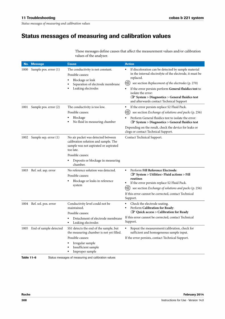
Roche February 2014
308 Instructions for Use · Version 14.0
11 Troubleshooting cobas b 221 systemStatus messages of measuring and calibration values
Status messages of measuring and calibration values
These messages define causes that affect the measurement values and/or calibration values of the analyzer.
No. Message Cause Action
1000 Sample pos. error (1) The conductivity is not constant.
Possible causes:
o Blockage or leako Separation of electrode membraneo Leaking electrodes
o If discoloration can be detected by sample material in the internal electrolyte of the electrode, it must be replaced.
U see section Replacement of the electrodes (p. 270)
o If the error persists perform General fluidics test to isolate the error:h System > Diagnostics > General fluidics testand afterwards contact Technical Support
1001 Sample pos. error (2) The conductivity is too low.
Possible causes:
o Blockageo No fluid in measuring chamber
o If the error persists replace S2 Fluid Pack.
U see section Exchange of solutions and packs (p. 256)
o Perform General fluidics test to isolate the error:h System > Diagnostics > General fluidics test
Depending on the result, check the device for leaks or clogs or contact Technical Support.
1002 Sample sep. error (1) No air packet was detected between calibration solution and sample. The sample was not aspirated or aspirated too late.
Possible causes:
o Deposits or blockage in measuring chamber.
Contact Technical Support.
1003 Ref. sol. asp. error No reference solution was detected.
Possible causes:
o Blockage or leaks in reference system
o Perform Fill Reference Electrode:h System > Utilities> Fluid actions > Fill routines
o If the error persists replace S2 Fluid Pack.
U see section Exchange of solutions and packs (p. 256)
If this error cannot be corrected, contact Technical Support.
1004 Ref. sol. pos. error Conductivity level could not be maintained.
Possible causes:
o Detachment of electrode membraneo Leaking electrodes
o Check the electrode seating.o Perform Calibration for Ready:h Quick access > Calibration for Ready
If this error cannot be corrected, contact Technical Support.
1005 End of sample detected SS1 detects the end of the sample, but the measuring chamber is not yet filled.
Possible causes:
o Irregular sampleo Insufficient sampleo Improper sample
o Repeat the measurement/calibration, check for sufficient and homogeneous sample input.
If the error persists, contact Technical Support.
Table 11-6 Status messages of measuring and calibration values

Roche February 2014
Instructions for Use · Version 14.0 309
cobas b 221 system 11 TroubleshootingStatus messages of measuring and calibration values
1006 Irregular sample (1) The measuring chamber is not filled homogeneously.
Possible causes:
o The sample was irregularo Leak in measuring channelo Air bubbles were detected in the
measuring channel
o Repeat measurement/calibration.
If the error persists, contact Technical Support.
1007 Cuvette not empty A sample detection was not possible.
Possible causes:
o Deposits in the cuvetteo Light level too low
o Perform Internal cleaning:h System > Wash & Cleaning > Clean module > select appropriate module and press Start internal cleaning.
o If the error persists replace PP tube (main pump).
U see section Exchanging the peristaltic pump tubes
(p. 266)
If error cannot be corrected, contact Technical Support.
1008 Irregular sample (2) The conductivity changed after closing the valve at the measuring chamber input.
Possible causes:
o Insufficient wetting in the measuring channel
o Separation of the electrode diaphragm
o Leaky electrode
o Perform Wetting routine:h System > Utilities > Fluid actions
If error cannot be corrected, contact Technical Support.
1009 Sample pos. error (3) The measuring signal was not constant or the measuring channel was not uniformly filled.
Possible cause:
o Sample was fragmented.
o Ensure sufficient, uniform sample input.
If the error persists, contact Technical Support.
1010 Sample pos. error (4) The conductivity was too high:
Possible causes:
o Aspiration problems with standby solution
o PP tube defective
o Check PP tube (MSS outlet) and if necessary replace.
U see section Exchanging the peristaltic pump tubes
(p. 266)
o Perform Aspirate standby solution:h System > Utilities > Fluid actions > Fill routines
If error cannot be corrected, contact Technical Support.
1011 Sample pos. error (5) No constant conductivity at sensor input was detected.
Possible causes:
o Blockage or leako PP tube (MSS outlet) defective
o Check PP tube (MSS outlet) and if necessary replace
U see section Exchanging the peristaltic pump tubes
(p. 266)
o Perform Aspirate standby solution:h System > Utilities > Fluid actions > Fill routines
o Perform Calibration for Ready:h Quick access > Calibration for Ready
o If error persists perform Wetting routine:h System > Utilities > Fluid actions
o If the error persists perform General fluidics test:h System > Diagnostics and afterwards contact Technical Support.
No. Message Cause Action
Table 11-6 Status messages of measuring and calibration values

Roche February 2014
310 Instructions for Use · Version 14.0
11 Troubleshooting cobas b 221 systemStatus messages of measuring and calibration values
1012 Sample pos. error (6) Conductivity at sensor input was too low.
Possible causes:
o Blockageo No fluid in measuring chambero PP tube (MSS outlet) defective
o Check PP tube (MSS outlet) and if necessary replace
U see section Exchanging the peristaltic pump tubes
(p. 266)
o Perform the fill routine Aspirate standby solution:h System > Utilities > Fluid actions > Fill routines
o Perform Calibration for Ready:h Quick access > Calibration for Ready
o If error persists perform Wetting routine:h System > Utilities > Fluid actions
o If the error persists perform General fluidics test:h System > Diagnostics and afterwards contact Technical Support.
1013 Sample sep. error (2) MSS: No air packet was detected between calibration solution and sample. The sample was not aspirated or aspirated too late.
Possible causes:
o Deposits or blockage in measuring channel.
o PP tube (MSS outlet) defective
o Check PP tube (MSS outlet) and if necessary replace
U see section Exchanging the peristaltic pump tubes
(p. 266)
o Perform Aspirate standby solution:h System > Utilities > Fluid actions > Fill routines
o Perform Calibration for Ready:h Quick access > Calibration for Ready
o If error persists perform Wetting routine:h System > Utilities > Fluid actions
o If the error persists perform General fluidics test:h System > Diagnostics and afterwards contact Technical Support.
1014 Sample pos. error (7) Conductivity at BSA sensor is too low.
Possible causes:
o Air bubbleso Poor wetting
o Perform MSS polarization:h System > Utilities (follow the instructions on the screen)
o Insert sufficiently large samples
If error cannot be corrected, contact Technical Support.
1015 Sample pos. error (8) Conductivity at lactate sensor is too low.
Possible causes:
o Air bubbleso Poor wetting
o Perform MSS polarization:h System > Utilities(follow the instructions on the screen)
o Insert sufficiently large samples
If error cannot be corrected, contact Technical Support.
1016 Sample pos. error (9) Conductivity at glucose sensor is too low.
Possible causes:
o Air bubbleso Poor wettingo
o Perform MSS polarization:h System > Utilities(follow the instructions on the screen)
o Insert sufficiently large samples
If error cannot be corrected, contact Technical Support.
1017 Sample pos. error (10) MSS: Conductivity was too low at the sensor input after positioning the sample/calibration solution in the measuring chamber.
Possible causes:
o The sample/calibration solution was non-uniform
o Insufficient sample/calibration solution detected
o Insufficient wetting of the measuring channel
Ensure sufficient, uniform sample input.
o Perform Wetting routine MSS:h System > Utilities > Fluid actions
o If the error cannot be corrected, replace MSS cassette.
U see section Changing the MSS cassette
(cobas b 221<5> system and cobas b 221<6> system
only) (p. 280)
No. Message Cause Action
Table 11-6 Status messages of measuring and calibration values

Roche February 2014
Instructions for Use · Version 14.0 311
cobas b 221 system 11 TroubleshootingStatus messages of measuring and calibration values
1020 Sample distr. error (1) Unable to remove excess sample.
Possible causes:
o Clogging or leaky points during positioning
o Perform General fluidics test to isolate the error.h System > Diagnostics
Depending on the result, check the device for leaks or clogs or contact Technical Support.
1021 Sample distr. error (2) No solution detected at SS3 although SS2 detected a solution.
Possible causes:
o Cloggingo Sample inlet path leaky
o Perform Wash:h System > Wash & Cleaning > Wash
o If the error persists, perform General fluidics test to isolate the errorh System > Diagnostics > General fluidics test
Depending on the result, check the device for leaks or clogs or contact Technical Support.
1022 Sample distr. error (3) Sample excess could not be extracted via transverse channel.
Possible causes:
o Blockage
o Perform Wash:h System > Wash & Cleaning > Wash
o If the error persists, perform General fluidics test to isolate the errorh System > Diagnostics > General fluidics test
Depending on the result, check the device for leaks or clogs or contact Technical Support.
1023 Sample distr. error (4) SS4 did not detect solution
Possible causes:
o Blockage
o Perform Wash:h System > Wash & Cleaning > Wash
o If the error persists, perform General fluidics test to isolate the errorh System > Diagnostics > General fluidics test
Depending on the result, check the device for leaks or clogs or contact Technical Support.
1024 No sample detected (1) SS3 and SS2 did not detect a sample.
Possible causes:
o No more sample available for the Hb module
o Insert sufficient sample amount, repeat measurement.
If the error persists, contact Technical Support.
1025 No sample detected (2) ISE: No constant conductivity of the sample was detected.
Possible causes:
o Fragmented sample in sample distributor
o Ensure sample entry is free of air bubbles. Repeat measurement.
If the error persists, contact Technical Support.
1026 No sample detected (3) ISE: No constant conductivity of the sample was detected.
Possible causes:
o Fragmented sample in sample distributor
o Ensure sample entry is free of air bubbles. Repeat measurement.
If the error persists, contact Technical Support.
1027 No sample detected (4) No sample detected in Hb module (tHb/SO2 or COOX module, depending
on the configuration).
Possible causes:
o Sample path leaky or cloggedo Cuvette holder is leakyo Tubing of main pump is defective
o Check PP tube (main pump) and if necessary replace
U see section Exchanging the peristaltic pump tubes
(p. 266)
o Perform Wash:h System > Wash & Cleaning > Wash
o If the error persists perform General fluidics test to isolate the errorh System > Diagnostics and afterwards contact Technical Support.
No. Message Cause Action
Table 11-6 Status messages of measuring and calibration values

Roche February 2014
312 Instructions for Use · Version 14.0
11 Troubleshooting cobas b 221 systemStatus messages of measuring and calibration values
1028 Insufficient sample(1) No sample detected in Hb module (tHb/SO2 or COOX module, depending
on the configuration).
Possible causes:
o The sample was irregularo Sample was insufficient
o Repeat measurement/calibration, check for sufficient and homogeneous sample input.
If the error persists, contact Technical Support.
1029 Insufficient sample(2) Insufficient sample for BG module was detected.
Possible causes:
o The sample was irregularo Sample was insufficient
o Repeat measurement/calibration, check for sufficient and homogeneous sample input.
If the error persists, contact Technical Support.
1030 Insufficient sample(3) Insufficient sample for ISE module was detected.
Possible causes:
o The sample was irregularo Sample was insufficient
o Repeat measurement/calibration, check for sufficient and homogeneous sample input.
If the error persists, contact Technical Support
1031 Insufficient sample(4) insufficient sample for MSS module was detected.
Possible causes:
o The sample was irregularo Sample was insufficient
o Repeat measurement/calibration, check for sufficient and homogeneous sample input.
o With non calibrated sensors perform fill routine Aspirate CAL 2/3/4:h System > Utilities > Fluid actions > Fill routines
o Perform Calibration for Ready:h Quick access > Calibration for Ready
If the error persists, contact Technical Support.
1032 Sample distr. error (5) No calibration solution 1 (CAL 1) detected.
Possible causes:
o Blockage or leako Tubing of main pump is defective
o Check PP tube (main pump)o Perform Aspirate CAL 1:h System > Utilities > Fluid actions > Fill routines
o If this error cannot be corrected, replace main pump tube
U see section Exchanging the peristaltic pump tubes
(p. 266)
If the error persists, contact Technical Support.
1036 Insufficient sample (5) Insufficient sample for MSS module was detected
Possible causes:
o The sample was irregularo Sample was insufficient
o Repeat the measurement/calibration, check for sufficient and homogeneous sample input.
o With non calibrated sensors perform fill routine Aspirate CAL 2/3/4:h System > Utilities > Fluid actions > Fill routines
o Perform Calibration for Ready:h Quick access > Calibration for Ready
If the error persists, contact Technical Support.
1037 No sample detected (8) No sample detected in hemolyzer:
Possible causes:
o Sample path leaky or blocked
o Perform Hemolyzer test:h System > Component test > Aggregates > Hemolyzer
o If the error persists perform General fluidics test to isolate the errorh System > Diagnostics > General fluidics test and afterwards contact Technical Support.
No. Message Cause Action
Table 11-6 Status messages of measuring and calibration values

Roche February 2014
Instructions for Use · Version 14.0 313
cobas b 221 system 11 TroubleshootingStatus messages of measuring and calibration values
1038 No sample detected (9) No rinse solution from the Hb module detected (tHb/SO2 or COOX module, depending on the configuration) (Calibration).
Possible causes:
o Sample path leaky or blocked
o Perform Wash:h System > Wash & Cleaning > Wash
o If the error persists perform General fluidics test to isolate the errorh System > Diagnostics > General fluidics test and afterwards contact Technical Support.
1050 No sample in SIP No sample detected in the sample inlet path at SS2 or SS6.
Possible causes:
o No sample was inserted
o If this error occurs as part of a calibration, clean the T&D disk.h System > Wash & cleaning > Clean input unit
o Perform Wash:h System > Wash & Cleaning > Wash
o If the error persists perform General fluidics test to isolate the errorh System > Diagnostics > General fluidics test
Depending on the result, check the device for leaks or clogs or contact Technical Support.
1051 No AQC sample detected
No sample was detected at SS5.
Possible causes:
o Sample path leaky or blocked
o Perform Wash AQC:h System > Wash & Cleaning > Wash AQC
o If the error persists perform General fluidics test to isolate the errorh System > Diagnostics > General fluidics test
and afterwards contact Technical Support.
1052 No vacuum No regulated vacuum could be build up during aspiration process.
Possible causes:
o Vacuum system defective
o Perform test function Vacuum system:h System > Component test > Control sensors
If the error persists, contact Technical Support.
2004 Repro. not OK Sensor signal cannot be reproduced
Possible causes:
o Measuring channel contaminatedo Bubbles on the diaphragm in the
inside electrolyte of the electrodeo Interference signals in the
measuring channel during measurement value acquisition
o Interference signals via the reference electrode during measured value acquisition
o Sensitivity loss of the electrode
o Perform Calibration for Ready:h Quick access > Calibration for Ready
o If error cannot be corrected, performh Wetting routine:h System > Utilities > Fluid actions
o Check electrode for bubbles: carefully tap against the electrode body with a finger nail to release any air bubbles from the membrane.
o If error cannot be corrected, replace the electrode
U see section Replacement of the electrodes (p. 270)
o If the sample channel is visibly soiled, perform Internal cleaning:h System > Wash & Cleaning > Clean module > select appropriate module and press Start internal cleaning.
o If the error concerns the parameter s pH, Urea, or several ISE parameters, perform Fill reference electrode:h System > Utilities > Fluid actions > Fill routines
o If the error persists replace reference electrode
U see section Changing the reference electrode (p. 278)
2009 Recal. not OK Signal difference occurring during recalibration of PCO2 was too large.
Possible causes:
o Invalid sample type used
o Perform Calibration for Ready:h Quick access > Calibration for Ready
o If the error persists, replace electrode
U see section Replacement of the electrodes (p. 270)
No. Message Cause Action
Table 11-6 Status messages of measuring and calibration values

Roche February 2014
314 Instructions for Use · Version 14.0
11 Troubleshooting cobas b 221 systemStatus messages of measuring and calibration values
2011 Sensor signal instability Sensor signal cannot be reproduced.
Possible causes:
o Invalid sample type is being usedo Measuring channel contaminatedo Air bubbles at the membrane in the
internal electrolyte of the electrodeso Interference signals in the
measuring channel during measurement acquisition
o Interference signals via reference electrodes during measurement acquisition
o If this interference applies to the complete module, the reference electrode must be replaced
U see section Changing the reference electrode (p. 278)
o In the case of individual electrodes, they must be checked for air bubbles. Carefully tap against the electrode body with a finger nail to release any air bubbles from the membrane
U see section Replacement of the electrodes (p. 270)
o Perform Calibration for Ready:h Quick access > Calibration for Ready
o Start Stability monitor:h System > Diagnostics > Stability monitor and check Details of the Sensor slope.
o IIf the electrode/MSS cassette is defective, it is displayed. Replace the corresponding electrode or the MSS cassette
U see section Replacement of the electrodes
(p. 270) or Changing the MSS cassette
(cobas b 221<5> system and cobas b 221<6> system
only) (p. 280)
2012 Sensor signal drifting Sensor signal is too high.
Possible causes:
o Invalid sample type is being usedo Rinse contaminatedo Rinse - problem during aspirationo Air bubbles at the membrane in the
internal electrolyte of the electrodeso Interference signals in the
measuring channel during measurement acquisition
o Interference signals via reference electrodes during measurement acquisition
o Perform Calibration for Ready:h Quick access > Calibration for Ready
o If error cannot be corrected, start Stability monitor:h System > Diagnostics > Stability monitor and check Details of the Sensor slope.
o If the electrode/MSS cassette is defective, it is displayed. Replace the corresponding electrode or MSS cassette
U see section Replacement of the electrodes
(p. 270) or Changing the MSS cassette
(cobas b 221<5> system and cobas b 221<6> system
only) (p. 280)
o Check electrode for air bubbles:Carefully tap against the electrode body with a finger nail to release any air bubbles from the membrane. If error cannot be corrected, replace electrode
U see section Replacement of the electrodes (p. 270)
o If the error persists, perform Aspirate Rinse:h System > Utilities > Fluid actions > Fill routines
o If necessary, replace S1 Rinse Solution
U see section Exchange of solutions and packs (p. 256)
2016 Signal too high The first sampling value of the O2 zero point calibration is > 60 mV
Possible causes:
o An air bubble falsifies the calibrationo Non-uniform O2 zero point
solutiono PO2 electrode defective
o Perform Wetting routine for BG:h System > Utilities > Fluid actions
o If the error cannot be corrected, perform Aspirate solution O2 zero:h System > Utilities > Fluid actions > Fill routines
o If necessary, replace S2 Fluid Pack.
U see, section Exchange of solutions and packs
(p. 256)
o If the error persists, replace PO2 electrode.
U see, section Replacement of the electrodes (p. 270)
No. Message Cause Action
Table 11-6 Status messages of measuring and calibration values

Roche February 2014
Instructions for Use · Version 14.0 315
cobas b 221 system 11 TroubleshootingStatus messages of measuring and calibration values
2021 Drift alarm A drifting of the sensor signal was detected in the "Ready" state.
Possible causes:
o Electrode drifts are exceeding the specified limit values
o Invalid sample type is being usedo Wetting problems
In case of PO2:
o contamination possible
o Perform Calibration for Ready:h Quick access > Calibration for Ready
o Start Stability monitor:h System > Diagnostics > Stability monitor and check Details of the Sensor slope.
o If the electrode/MSS cassette is defective, it is displayed. Replace the corresponding electrode or the MSS cassette
U see section Replacement of the electrodes
(p. 270) or Changing the MSS cassette
(cobas b 221<5> system and cobas b 221<6> system
only) (p. 280)
In case of PO2 drift:
o Perform Internal cleaning:h System > Wash & Cleaning> Cleaning module > select appropriate module and press Start internal cleaning.
o If the error persists, optimize the cleaning interval:h Setup > Time & Intervals > Maintenance timing > BG cleaning change interval and/or sample counter or contact Technical Support.
2022 Ref. drift alarm IIn the "Ready" state drifting of the sensor signal was detected at the reference electrode.
Possible causes:
o Reference system fault due to bubbles
o Docking mechanism for S2 Fluid Pack soiled
o Perform Fill reference electrode:h System > Utilities > Fluid actions > Fill routines
o Perform Calibration for Ready:h Quick access > Calibration for Ready > Calibration for Ready
o Check S2 docking mechanism for contamination and if necessary clean it.
o If the error persists replace reference electrode
U see section Changing the reference electrode (p. 278)
2023 Sensitivity drift 1 point sensitivity drifts.
Possible causes:
o The sensor did not finished the start-up period and the 1 point sensitivity highly increases.
o Perform Calibration for Ready:h Quick access > Calibration for Ready
2024 Air bubble detected Before washing out the sample the conductivity value was not detected as pressure-stable.
Possible causes:
o PO2 electrode has not filled bubble-free
o Leaky sample path in BG
o Perform General fluidics test:h System > Diagnostics > General fluidics test if error occurs, contact Technical Support.
o Replace PO2 electrode.o Replace PCO2 electrode
No. Message Cause Action
Table 11-6 Status messages of measuring and calibration values

Roche February 2014
316 Instructions for Use · Version 14.0
11 Troubleshooting cobas b 221 systemStatus messages of measuring and calibration values
2028 Mean not OK Measurement value of calibration is outside the expected range.
Possible causes:
o Electrode limit exceeded
o Perform module-related system calibration:h System > Calibration > System calibration
o If several electrodes are affected, replace S2 Fluid Pack or S3 Fluid Pack (cobas b 221<5> system, cobas b 221<6> system only)
U see section Exchange of solutions and packs (p. 256)
o With PO2 electrode, check barometer:h System > Component test > Control sensors > Barometer
o If the error persists, replace electrode/MSS cassette
U see section Replacement of the electrodes (p. 270)
2029 ADC >>>>> Sensor signal is above the measuring range.
Possible causes:
o Reference system not filledo Leaky, empty electrode
o Perform Fill reference electrode:h System > Utilities > Fluid actions > Fill routines > Fill reference electrode
o Check seat of the electrode.o Perform General fluidics test:h System > Diagnostics > General fluidics test
o If the error persists, replace electrode/MSS cassette
U see section Replacement of the electrodes (p. 270)
2030 ADC <<<<< Sensor signal is below the measuring range.
Possible causes:
o Reference system not filledo Leaky, empty electrode
o Perform Fill reference electrode:h System > Utilities > Fluid actions > Fill routines > Fill reference electrode
o Check seat of the electrode.o Perform General fluidics test:h System > Diagnostics > General fluidics test
o If the error persists, replace electrode/MSS cassette
U see section Replacement of the electrodes (p. 270)
2031 Conditioning not OK Na electrode was not conditioned.
Possible causes:
o S2 Fluid Pack docking mechanism is leaking
o T&D leaking during aspiration of conditioning solution
o Perform Aspirate Na cond. solution:h System > Utilities > Fluid actions > Fill routines
o Perform Conditioning:h System > Utilities > Fluid actions
o Insert a new S2 Fluid Pack.o If the error persists, perform General fluidics test:h System > Diagnostics > General fluidics test and correct the leak.
2035 Linearity not OK The sensitivity of the sensor is too low.
Possible causes:
o Sensor worn out
o Replace the MSS cassette.
U see section Changing the MSS cassette
(cobas b 221<5> system and cobas b 221<6> system
only) (p. 280)
o If the error cannot be corrected, replace S3 Fluid Pack.
U see section Exchange of solutions and packs (p. 256)
2036 Interference sensitivity The sensitivity of the sensor is too low.
Possible causes:
o Sensor worn out
o Replace MSS cassette.
U see section Changing the MSS cassette
(cobas b 221<5> system and cobas b 221<6> system
only) (p. 280)
o If the error cannot be corrected, replace S3 Fluid Pack.
U see section Exchange of solutions and packs (p. 256)
No. Message Cause Action
Table 11-6 Status messages of measuring and calibration values

Roche February 2014
Instructions for Use · Version 14.0 317
cobas b 221 system 11 TroubleshootingStatus messages of measuring and calibration values
2040 Cuvette not OK Check of layer thickness outside the expected range.
Possible causes:
o Cuvette is contaminatedo Incorrect target value
o Perform Polychromator calibration:h System > Calibration > Polychromator calibration
o Perform COOX calibration:h System > Calibration > COOX calibration
2041 Ref. point not OK Reference point is outside the expected range
Possible causes:
o Sample feeding clogged
o Perform Wash:h System > Wash & Cleaning > Wash
o If the error persists, perform General fluidics test to isolate the error:h System > Diagnostics > General fluidics test and afterwards contact Technical Support.
2042 Wavelength not OK (1) One specific wavelength is outside the expected range.
o Perform Polychromator calibration:h System > Calibration > Polychromator calibration
If the error persists, contact Technical Support.
2043 Hemolysis not OK (1) Hemolyzer is not ready o Perform Hemolyzer test:h System > Component test > Aggregates > Hemolyzer
2044 Hemolysis not OK (2) Hemolyzer power is outside the expected range.
o Visually check the drying operation.
2070 Sensor signal unstable tHb sensor signal is disturbed
Possible causes:
o Irregular sampleo Sample feeding is leaking or clogged
o Perform Internal cleaning:h System > Wash & Cleaning> Cleaning module > tHb/SO2 module > Start internal cleaning
o If the error persists, perform General fluidics test to isolate the error:h System > Diagnostics > General fluidics test
o Replace S1 Rinse Solution.
U see section Exchange of solutions and packs (p. 256)
If the error persists, contact Technical Support
2071 Measuring path dirty The absolute limits of water calibration are outside the specified range.
Possible causes:
o Contaminated or defective sensor
o Perform Internal cleaning:h System > Wash & Cleaning> Cleaning module > select appropriate module and press Start internal cleaning, repeat as necessary.
o Replace S1 Rinse Solution.
U see section Exchange of solutions and packs (p. 256)
If the error persists, contact Technical Support.
3000 D2/D3 not performed MSS standby solution was not aspirated.
Possible causes:
o Faulty aspiration of standby solutiono Faulty aspiration of reference
solution
o Check Aspirate standby solution:h System > Utilities > Fluid actions > Fill routines
o Check aspiration of reference solution:h System > Utilities > Fluid actions > Fill routines
o Perform Calibration for Ready:h Quick access > Calibration for Ready
No. Message Cause Action
Table 11-6 Status messages of measuring and calibration values

Roche February 2014
318 Instructions for Use · Version 14.0
11 Troubleshooting cobas b 221 systemStatus messages of measuring and calibration values
3001 FMS volume error Time-out error during aspiration of calibration solution.
Possible causes:
o Blockage or leak
o Check Aspirate CAL B: h System > Utilities > Fluid actions > Fill routines
o Perform General fluidics test:h System > Diagnostics > General fluidics test
Depending on the result, check the device at the displayed position for leaks or clogs or contact Technical Support.
o Call up Calibration for Ready: h Quick access > Calibration for Ready
o Replace S2 Fluid Pack
U see section Exchange of solutions and packs (p. 256)
If the error persists, contact Technical Support.
3002 Temperature error The module temperature is outside the permitted range.
Possible causes:
o Poor heating contacto Fan failureo Heating failureo Air filter heavily soiled or covered
o Check the temperature signals.
If the temperature is outside the specified range for a long period of time, inform Technical Support.
3003 FMS error Incorrect deviation from specified value and measurement value of FMS.
Possible causes:
o Blockage or leako Defective mixer valveo Defective air valveo Blockage or leak
o To isolate error, check Aspirate CAL B:h System > Utilities > Fluid actions > Fill routines > Aspirate CAL B
o Check Aspirate CAL A: h System > Utilities > Fluid actions > Fill routines > Aspirate CAL A
o Perform General fluidics test:h System > Diagnostics > General fluidics test
Depending on the result, check the device at the displayed position for leaks or clogs or contact Technical Support.
o Call up Calibration for Readyh Quick access > Calibration for Ready
o Replace S2 Fluid Pack
U see section Exchange of solutions and packs (p. 256)
3004 AQC module error" The required position was not reached. o Perform AQC positioning test:h System> Component test > Aggregates > AutoQC motors > AQC-positions
o Open AutoQC drawer and remove the ampoule holder, move to service position and go back to home position again.
o Reinsert ampoule holder and close AutoQC drawer.o Perform Wash AQC:h System > Wash & Cleaning > Wash AQC
If the error persists, contact Technical Support.
No. Message Cause Action
Table 11-6 Status messages of measuring and calibration values

Roche February 2014
Instructions for Use · Version 14.0 319
cobas b 221 system 11 TroubleshootingStatus messages of measuring and calibration values
3013 Ref. point D1 not OK Problem during precalibration.
Possible causes:
o Faulty aspiration of standby solutiono Faulty aspiration of MSS reference
solution
o Check Aspirate standby solution:h System > Utilities > Fluid actions > Fill routines
o Check Fill ref. electrode MSS:h System > Utilities > Fluid actions > Fill routines
o Perform MSS conductivity path test with standby solution:h System > Component test > Control sensors > Contact paths
3014 Ref. point not OK Problem during precalibration.
Possible causes:
o Faulty aspiration of standby solutiono Faulty aspiration of MSS reference
solution
o Check Aspirate standby solution:h System > Utilities > Fluid actions > Fill routines
o Check Fill ref. electrode MSS: h System > Utilities > Fluid actions > Fill routines
o Perform MSS conductivity path test with standby solution: h System > Component test > Control sensors > Contact paths
3022 Conductivity not OK Conductivity calibration was not exited correctly.
o Print out Sensor report and check the error messages for conductivity with calibration solution CAL B or CAL A: h Info > Miscellaneous reports
3033 0P not OK O2 zero calibration was not exited
correctly.
Possible causes:
o Aspireate O2 zero not oko Soiling or leak
o Perform Aspirate O2 zero point solution:h System > Utilities > Fluid actions > Fill routines
o Check fill port and the T&D disc for soiling
U see Maintenance (p. 245)
o Replace S2 Fluid Pack.
U see section Exchange of solutions and packs (p. 256)
3034 Invalid measured value Elapsed time between sample and Cal 1 too high. The measurement value is blocked because of unclear sensor signal drift.
o Perform Calibration for Ready:h Quick access > Calibration for Ready
4003 Calibration pending (1) Sensor reinserted, no calibration values available.
o Perform Calibration for Ready:h Quick access > Calibration for Ready
4008 Calibration pending (2) Calibration is pending or was canceled. o Perform Calibration for Ready:h Quick access > Calibration for Ready
4024 Calibration pending (3) Sensor is or was deactivated. o Perform Calibration for Ready:h Quick access > Calibration for Ready
5006 Calculation error (1) UC calculation error.
Possible causes:
o An unapproved calculation operation occurred.
o Remove bottles/packs and reinsert them.
If the error persists, contact Technical Support.
5007 Calculation error (2) UC calculation error.
Possible causes:
o An unapproved calculation operation occurred.
o Remove the affected electrode and reinsert it.
If the error persists, contact Technical Support.
No. Message Cause Action
Table 11-6 Status messages of measuring and calibration values

Roche February 2014
320 Instructions for Use · Version 14.0
11 Troubleshooting cobas b 221 systemStatus messages of measuring and calibration values
5010 Calculation error (3) UC calculation error (COOX).
Possible causes:
o An unapproved calculation operation occurred.
o Turn the instrument off and on again.
If the error persists, contact Technical Support.
5011 Calculation error (4) UC calculation error (4) (COOX).
Possible causes:
o An unapproved calculation operation occurred.
o Perform Polychromator calibration:h System > Calibration > Polychromator calibration
o Turn the instrument off and on again.
If the error persists, contact Technical Support.
5012 Calculation error (5) UC calculation error (5) (COOX).
Possible causes:
o An unapproved calculation operation occurred.
o Check the cuvette for soiling.o Perform Polychromator calibration:h System > Calibration > Polychromator calibration
o Turn the instrument off and on again.
If the error persists, contact Technical Support.
6026 ADC error o To correct the error, turn the instrument off, wait at least 3 minutes, and turn it back on.
If this error cannot be corrected, contact Technical Support.
6030 COOX HW error A hardware error occurred at the COOX module.
U see Details of module stop 20068 (p. 301), 20069
(p. 301) and 20071 (p. 301).
6031 Neon lamp not OK The light value of the neon lamp is too low.
Possible causes:
o Cuvette soiledo Optical fiber damagedo Polychromator electronics defective
o Perform Internal cleaning:h System > Wash & Cleaning > Cleaning module > select appropriate module and press Start internal cleaning
o Perform Polychromator calibration:h System > Calibration > Polychromator calibration
If the error persists, contact Technical Support.
6032 Halogen lamp not OK The light value of the halogen lamp is too low.
Possible causes:
o Cuvette soiledo Optical fiber damagedo Polychromator electronics defective
o Perform Internal cleaning:h System > Wash & Cleaning > Cleaning module > select appropriate module and press Start internal cleaning
o Perform Polychromator calibration:h System > Calibration > Polychromator calibration
If the error persists, contact Technical Support.
7034 Solution exhausted The pH value of the O2 zero point
solution is < 5.
Possible causes:
o Solution exhaustedo Impurity in pack
o To correct the error replace S2 Fluid Pack
U see section Exchange of solutions and packs (p. 256)
8036 IfS not OK The BSA/Glu or BSA/Lac ratios in CAL 3 are outside the range.
Possible causes:
o Interference correction not possible
o Perform Calibration for Ready:h Quick access > Calibration for Ready
o If the error cannot be corrected, replace MSS cassette
U see section Changing the MSS cassette
(cobas b 221<5> system and cobas b 221<6> system
only) (p. 280)
No. Message Cause Action
Table 11-6 Status messages of measuring and calibration values

Roche February 2014
Instructions for Use · Version 14.0 321
cobas b 221 system 11 TroubleshootingStatus messages of measuring and calibration values
8061 Interferences (1) The calculated tHb value is invalid
Possible causes:
o Interferences o Unsuitable sample type used
o Check sample material and, if necessary, reenter the sample.
If the error persists, contact Technical Support.
8062 Interferences (2) The calculated Hb derivatives are invalid.
Possible causes:
o Interferences o Unsuitable sample type used
o Check sample material and, if necessary, reenter the sample.
If the error persists, contact Technical Support.
8063 Interferences (3) The calculated value of Bilirubin is invalid.
Possible causes:
o Interferences o Unsuitable sample type used
o Check sample material.
If the error persists, contact Technical Support.
8070 IfS repro. not OK Non-reproducible sensor signal at interference sensor.
Possible causes:
o Unsuitable sample type is being used
o Perform Wetting routine MSS:h System > Utilities > Fluid actions
If the error persists, change the MSS cassette.
U see section, Changing the MSS cassette
(cobas b 221<5> system and cobas b 221<6> system
only) (p. 280)
8071 - 8072
IfS calculation error (1) - (2)
UC calculation error (1) on interference sensor.
Possible causes:
o An unapproved calculation operation occurred
o Remove and reinsert S3 Fluid Pack.
8073 IfS sensor signal unstable Interference sensor signal cannot be reproduced.
Possible causes:
o Unsuitable sample type is being usedo Measuring channel contaminatedo Interference signals in the
measuring channel during measurement acquisition
o Interference signals via reference electrodes during measurement acquisition
o If this interference applies to the complete module, replace reference electrode
U see section Changing the reference electrode (p. 278)
o Perform Calibration for Ready:h Quick access > Calibration for Ready
o If error cannot be corrected start Stability monitor:h System > Diagnostics > Stability monitor and check Details of the Sensor slope.
o If the cassette is defective, it is displayed and should be replaced
U see section Changing the MSS cassette
(cobas b 221<5> system and cobas b 221<6> system
only) (p. 280)
8074 IfS ref. point not OK Problem at reference point of standby solution at interference sensor.
Possible causes:
o Aspiration of MSS standby solution not ok
o Aspiration of MSS reference solution not ok
o Check Aspirate standby solution:h System > Utilities > Fluid actions > Fill routines
o Check Fill ref. electrode MSS:h System > Utilities > Fluid actions > Fill routines
o Perform MSS conductivity path test with standby solution:h System > Component test > Control sensors > Contact paths
8075 IfS ADC error o To correct the error turn the instrument off, wait at least 3 minutes, and turn it back on.
If this error cannot be corrected, contact Technical Support.
No. Message Cause Action
Table 11-6 Status messages of measuring and calibration values

Roche February 2014
322 Instructions for Use · Version 14.0
11 Troubleshooting cobas b 221 systemStatus messages of measuring and calibration values
8076 IfS mean not OK Calibration end value of an IfS is outside the range.
Possible causes:
o Problems with transponder of S3 Fluid Pack
o Replace S3 Fluid Pack.
U see section Exchange of solutions and packs
(p. 256).
o If the error persists replace MSS cassette.o see section Changing the MSS cassette
(cobas b 221<5> system and cobas b 221<6> system only) (p. 280)
8077 IfS ADC >>>>> Interference sensor signal is above ADC range
Possible causes:
o Reference system not filledo Leak in the measuring channel
o Perform Fill reference electrode:h System > Utilities > Fluid actions > Fill routines
o Check seat of the electrode.o If the error persists, replace electrode/MSS cassette.
U see section Replacement of the electrodes
(p. 270) or section Changing the MSS cassette
(cobas b 221<5> system and cobas b 221<6> system
only) (p. 280)
8078 IfS ADC <<<<< Interference sensor signal is below ADC range
Possible causes:
o Reference system not filledo Leak in the measuring channel
o Perform Fill reference electrode:h System > Utilities > Fluid actions > Fill routines
o Check seat of the electrode.o If the error persists, replace electrode/MSS cassette.
U see section Replacement of the electrodes
(p. 270) or section Changing the MSS cassette
(cobas b 221<5> system and cobas b 221<6> system
only) (p. 280)
8080 Interferences (4) Detected sample type is invalid.
Possible causes:
o Interferences o Unsuitable sample type used
o Check sample material.
8081 Interferences (5) The calculated COHb value is outside the permitted range.
Possible causes:
o Interferenceso Unsuitable sample type used
o Check sample material.
8082 Interferences (6) The calculated SO2 value is outside the permitted range.
Possible causes:
o Interferenceso Unsuitable sample type used
o Check sample material.
8083 Sample type conflict Detected sample type is invalid.
Possible causes:
o Unsuitable sample type used
o Check sample material.
8084 Invalid sample type A different blood type than arterial or capillary blood was used.
Possible causes:
o All calculation values calculated from measurement values with arterial blood cannot be output.
o Use arterial or capillary blood as sample material and set the correct blood type.
No. Message Cause Action
Table 11-6 Status messages of measuring and calibration values

Roche February 2014
Instructions for Use · Version 14.0 323
cobas b 221 system 11 TroubleshootingStatus messages of measuring and calibration values
9000 Calculation error (3) PC calculation error.
Possible causes:
o An unapproved calculation operation occurred.
o Contact Technical Support.
9001 Not activated Parameter is disabled for measurement (gray).
o Enable the parameter.
9002 Not calibrated Parameter is not calibrated (red X). o Perform Calibration for Ready:h Quick access > Calibration for Ready
9011 Interferences The BSA/Glu or BSA/Lac ratios are outside the range. Interference correction not possible.
o Check sample material and, if necessary, reenter the sample.
If the error persists, contact Technical Support.
No. Message Cause Action
Table 11-6 Status messages of measuring and calibration values

Roche February 2014
324 Instructions for Use · Version 14.0
11 Troubleshooting cobas b 221 systemStatus messages on the measurement report
Status messages on the measurement report
Messages Causes
Out of range (-) Measurement value is outside (below) the normal range.
Out of range (+) Measurement value is outside (above) the normal range.
tHb not OK Indicates at the parameter SO2, that the tHb value is outside the normal range.
# ... check Hct result The Hct value is implausible.
? ... improper sample The selected sample type does not match the actual concentration.
(c) ... User correlation activated User defined correlation applied to the measurement value.
* ... demo mode Demo Mode active.
(q) ... qc warning Parameter is in QC warning state.
(!) … Sensor older than 28 days Sensor on board time exceeded.
# ... check plausibility The measured value is lower than the defined Limit of Quantitation (LoQ). The BSA/Glu or BSA/Lac ratios are outside the range. Interference correction not possible.
Table 11-7 Status messages on the measurement report

Roche February 2014
Instructions for Use · Version 14.0 325
cobas b 221 system 11 TroubleshootingBarcode
Barcode
If problems occur reading in with the PS2 hand-held scanner included in the scope of delivery, carry out the following steps:
P Barcode scanner troubleshooting
1 Make sure your scanner firmly connects with the interface connector of the instrument.
2 Inspect in detail the condition of the cable, e.g. by looking for broken areas, or loose cable parts.
3 Check the voltage supply by inspecting whether LED light is visible (continuously or flash light only). Additionally, the scanner prompts a trigger tone when reading a barcode.
4 Use the test function on the instrument to read in a barcode with known characters. In case the characters are transmitted and displayed correctly the barcode scanner will indicate this by a flash light and a trigger.
U see Reference Manual chapter Software modes, section Component test
5 In case of a problem, the characters are transmitted and/or displayed incorrectly, or even not transmitted. So proceed with the next step:
6 Unplug the barcode cable from the instrument.
7 Re-plug the barcode cable.
8 Repeat step 4 for checking again the functionality. If still not ok proceed with the next step.
9 Set the scanner by using the barcode manual to default:
o Take the barcode scanner programming manual and read the barcode labeled as "Roche Factory Reset".
If the error persists, contact Technical Support.
S

Roche February 2014
326 Instructions for Use · Version 14.0
11 Troubleshooting cobas b 221 systemBarcode

February 2014
Appendix
12 List of consumables ........................................................................................................................ 329
13 Glossary .......................................................................................................................................... 335


Roche February 2014
Instructions for Use · Version 14.0 329
cobas b 221 system 12 List of consumablesTable of contents
List of consumables 12
In this chapter, all necessary consumables and order numbers are listed.
In this chapter Chapter 12Order information............................................................................................................. 331
Electrodes..................................................................................................................... 331
Solutions....................................................................................................................... 332
QC material.................................................................................................................. 332
Accessories ................................................................................................................... 333

Roche February 2014
330 Instructions for Use · Version 14.0
12 List of consumables cobas b 221 systemTable of contents

Roche February 2014
Instructions for Use · Version 14.0 331
cobas b 221 system 12 List of consumablesOrder information
Order information
To measure the respective parameter following products are required:
Electrodes
Parameter
Cl- Na+ K+ Ca2+ PCO2 PO2 pH tHb/SO2 COOX/Bili MSS
Chloride Electrode
03111571180
X + + + + + + + + +
Sodium Electrode
03111598180
+ X + + + + + + + +
Potassium Electrode
03111628180
+ + X + + + + + + +
Calcium Electrode
03111644180
+ + + X + + + + + +
PCO2 Electrode
03111679180
+ + + + X + + + + +
PO2 Electrode
03111695180
+ + + + + X + + + +
pH Electrode
03111717180
+ + + + + + X + + +
Reference Electrode (1)
03111873180
X X X X X X X + + X
Reference Contact (RCon)
03112071180
X X X X X X X + + X
Sensor Contact (SCon)
03260909184
+ + + + + + + + + X
Micro Electrode Dummy
03111849035
X X X X X X X X X X
GLU/LAC/UREA Cassette(2)
03261085184
+ + + + + + + + + +
GLU/LAC Cassette
03260887184
+ + + + + + + + + X
GLU Cassette
03260895184
+ + + + + + + + + X
MSS Dummy Sensor
03351262001
+ + + + + + + + + +
Table 12-1
(1) The reference electrode must be replaced after 52 weeks of in-use time.
(2) Only for cobas b 221<6> system.
X Has to be installed
+ Dummy or electrode has to be used for proper filling of the measuring chamber
Table 12-2

Roche February 2014
332 Instructions for Use · Version 14.0
12 List of consumables cobas b 221 systemOrder information
Solutions
QC material
Parameter
Cl- Na+ K+ Ca2+ PCO2 PO2 pH tHb/SO2 COOX/Bili MSS
S1 Rinse Solution
03260917184
X X X X X X X X X X
S2 Fluid Pack
03260925184
X X X X X X X X X X
S3 Fluid Pack A
03260933184
X X X X X X X X X X
W Waste Container
03144054001
X X X X X X X X X X
Hb Calibrator
03110923035
- - - - - - - X X -
Table 12-3
X Has to be installed
Table 12-4
Parameter
Cl- Na+ K+ Ca2+ PCO2 PO2 pH tHb/SO2 COOX/Bili MSS
AUTO-TROL PLUS B, Level 1
03321169001
O O O O O O O O O O
AUTO-TROL PLUS B, Level 2
03321177001
O O O O O O O O O O
AUTO-TROL PLUS B, Level 3
03321185001
O O O O O O O O O O
COMBITROL PLUS B, Level 1
03321193001
O O O O O O O O O O
COMBITROL PLUS B, Level 2
03321207001
O O O O O O O O O O
COMBITROL PLUS B, Level 3
03321215001
O O O O O O O O O O
COOX/MSS Verification Material
03354628001(1)
O O O O O O O O O O
TS/MSS Verification Material
03354601001(a)
O O O O O O O O O O
Table 12-5
(1) Only for USA available.
O Can be used
Table 12-6

Roche February 2014
Instructions for Use · Version 14.0 333
cobas b 221 system 12 List of consumablesOrder information
Accessories
Parameter
Cl- Na+ K+ Ca2+ PCO2 PO2 pH tHb/SO2 COOX/Bili MSS
Deproteinizer
03110435180
O O O O O O O O O O
Adapter for Capillaries
03069931001
O O O O O O O O O O
Ampoule Adapter
03066762001
O O O O O O O O O O
Clot Catcher (1)
03112012180
O O O O O O O O O O
Clot Catcher PRO(2)
05689856001
O O O O O O O O O O
Cleaning Kit for Cl- Electrode
03112098035
O - - - - - - - - -
Adapters for Sample Container
03112101180
O O O O O O O O O O
Caps for Roche MICROSAMPLER
03112152180
O O O O O O O O O O
Thermo Printer Paper
03113361180 (HP0107)
O O O O O O O O O O
Roche MICROSAMPLER PROTECT, non sterile
05772494001 (200 pcs.)
O O O O O O O O O O
Roche MICROSAMPLER PROTECT, sterile
05772583001 (50 pcs.)
O O O O O O O O O O
Roche MICROSAMPLER PROTECT, with accessories
05772591001(3)
O O O O O O O O O O
Capillary Tubes, ~ 200 μL
03113477180 (MC0024)
O O O O O O O O O O
BS2 Blood Sampler (sterile)
03113493035 (MC0028)
O O O O O O O O O O
Capillary Tubes, ~ 115 μL
03113507035(MG0002)
O O O O O O O O O O
Plastic Capillary Tubes, ~ 140 μL
05174791001
O O O O O O O O O O
Table 12-7
(1) The Clot catcher is not suitable for measurements in syringe mode and in "Aspiration from syringe" mode.
(2) The Clot Catcher PRO is not suitable for measurements in syringe mode and in "Aspiration from syringe" mode.
(3) Only for USA available
O Can be used
- Do not use
Table 12-8

Roche February 2014
334 Instructions for Use · Version 14.0
12 List of consumables cobas b 221 systemOrder information
Parameter
Cl- Na+ K+ Ca2+ PCO2 PO2 pH tHb/SO2 COOX/Bili MSS
Sterile Capillary Holder
05174830001
- - - - O O O - - -
Caps for Capillary Tubes
03113647035 (RE0410)
O O O O O O O O O O
Customer Accessory Kit,
for cobas b 221<2>/<4>/<6> system
04975626001
O O O O O O O O O O
Table 12-9
O Can be used
- Do not use
Table 12-10

Roche February 2014
Instructions for Use · Version 14.0 335
cobas b 221 system"Ready" screen - Glass tube
Glossary 13
"Ready" screen Main window of the analyzer mode.
1P 1-point calibration: an automatic calibration of sensor parameters using a CAL1 solution.
2P 2-point calibration: an automatic calibration of all parameters using CAL1, CAL2, and standby solutions of different concentrations. Optionally, cuvette layer thickness can also be calibrated.
Acid Base Diagram The log PCO2/pH diagram serves
as a basis for showing the rearranged Henderson-Hasselbalch equation.
Alkaline basic
Analyzer Software mode for measuring, QC measurement, system functions, calibration, quick access.
AQC abbr. for AutoQC
Arterial blood Blood taken from the artery
AUTO-TROL PLUS B AutoQC material for controlling BG, ISE, Glu, Lac, Urea/BUN, COOX/Bilirubin
AUTO-TROL TS+ AutoQC material for controlling BG, ISE, Glu, Lac, Hct, tHb/SO2
AutoQC module The AutoQC module is a unit that automatically takes quality control measurements programmed by the user.
Barcode scanner PS2 hand-held scanner with integrated decoder for simple input of QC data, electrode data, patient or user identity.
BG abbr. for blood gas
BG measuring chamber The BG measuring chamber with its sensors serves for measuring the pH value and blood gas values PO2 and PCO2
Bilirubin is a yellow decomposition product of the red blood pigment, hemoglobin, or more exactly, that of the hemoglobin share.
Bottle compartment The bottle compartment contains the W Waste Container, the S1 Rinse Solution bottle, the S2 Fluid Pack (with the solutions for BG and ISE) and the S3 Fluid Pack (with the solutions for Glu, Lac and Urea/BUN - only cobas b 221<5> system and cobas b 221<6> system). The bottle compartment also contains the necessary docking mechanisms for transporting the fluids into or out of the system.
Bottle tool serves for emptying the W Waste Container and for degassing the S1 Rinse Solution.
BUN abbr. for blood urea nitrogen
Bypass nipple Connection between the sample inlet path and the transverse channel
Calibration for Ready A calibration is selected to bring all the activated parameters into the "Ready" condition.
Clip Plastic fastener on S2 Fluid Pack and S3 Fluid Pack.
Clot catcher Coagulum catcher for use with syringes and capillaries
COMBITROL PLUS B QC material for controlling BG, ISE, Glu, Lac, Urea/BUN, COOX/Bilirubin
COMBITROL TS+ QC material for controlling BG, ISE, Glu, Lac, Hct, tHb/SO2
Contact clip The MSS cassette inserted in the measuring chamber slit is pressed into position and thereby firmly positioned.
COOX module The oximeter module consists of the hemolyzer and the COOX measuring chamber. It is an optical sensor module for determining bilirubin (Bili), total hemoglobin (tHb), and the hemoglobin derivatives oxyhemoglobin (O2Hb), desoxyhemoglobin (HHb),
carboxyhemoglobin (COHb) and methemoglobin (MetHb).
Docking mechanism Serves as an interface between the packs or bottles and the fluid channels in the system
Dummy electrode A flow-through electrode without any measuring function serving as a placeholder.
Electrodes are flow-through electrodes with a visible sample channel.
Filling port Enables a sample to be injected or aspirated from syringes, Roche MICROSAMPLER, capillaries and ampule adapters.
Fixation lever serves for fixing the sensors in the measuring chamber
FMS Fluid mixing system. In combination with the main pump this system guarantees the correct mixture of the calibration solutions CAL A and CAL B from the S2 Fluid Pack for the next calibrations, with the aid of the valves VM and V19.
Glass tube see Sample inlet path (SIP) (p. 337)

Roche February 2014
336 Instructions for Use · Version 14.0
cobas b 221 systemHematocrit - Sample drip tray
Hematocrit in short, Hct, is the ratio of the volume of blood cells (mainly the red blood corpuscles) to the total volume of blood.
Hemoglobin is the main component of the erythrocytes and serves for transporting oxygen.
Hemolyzer The sample is exposed to a strong ultrasound field whereby the cell membranes of the erythrocytes are destroyed and the hemoglobin released.
Heparin salts are the only permissible anticoagulants
Input unit Consists of the T&D module and the sample drip tray.
ISE abbr. for ion-selective electrode
ISE measuring chamber The ISE measuring chamber with its sensors serves for measuring the
hematocrit value and the electrolyte values Na+, K+, Ca2+
and Cl-.
Levey-Jennings diagram QC statistical values chart
LF Conductivity
Linear bracket White plastic part of the peristaltic pump.
MC abbr. for "measuring chamber"
Measurement evaluation Before clinical decisions are made on the basis of the results, the plausibility of all the measuring results obtained must always be checked by medical specialists, thereby taking the clinical situation of the patient into account.
Measuring chamber cassette serves for transporting the samples and calibration solutions to the waste system after a measurement and/or calibration and for adding the reference and rinse solution S1.
Module stop A certain module is not ready for use. Nevertheless, the parameters of other modules can still be measured.
MSS abbr. for metabolite sensitive sensors
MSS cassette is a multi-parameter sensor and contains the spots for measuring Glu, Lac, Urea/Bun
MSS measuring chamber The MSS measuring chamber with its sensors serves for measuring glucose, lactate and urea/BUN.
MSS polarization serves for wetting and preparing the MSS cassette.
Multirules The valuation of the QC results is based on the Westgard rules and their interpretation for the blood gas analysis. The multirule procedure was derived from this. It enables malfunctions of the instrument to be detected at an early stage.
NIST standards define precise sera with certified expected values.
Patient Trend Diagram Using this diagram, the course of individual parameters (measuring and calculated values) of a patient over an indefinite period of time can be shown and printed out.
Peristaltic pump see Pumps (p. 336)
Plasma Plasma samples are obtained by centrifuging heparinized whole blood, whereby cellular cell parts of the blood are separated.
Pleural fluid Pleural fluid is a serous fluid produced by the pleurae.
Pleural space The thin space between the two pleural layers is known as the pleural space.
Plug monitoring Infrared light barrier for detecting plugged or unplugged sample containers.
Polychromator Light is refracted and focused on the surface of a photosensitive receiver (CCD).
PP abbr. for peristaltic pump.
Printer A low-noise thermoprinter with integrated paper cutter and optional paper winder.
Pumps The transport of the sample and the operating fluids is effected by means of up to three peristaltic pumps, depending on the design (main pump, MSS output pump, MSS input pump).
QC abbr. for quality control
QC material see AUTO-TROL PLUS B (p. 335), AUTO-TROL TS+ (p. 335), COMBITROL PLUS B (p. 335), COMBITROL TS+ (p. 335)
Quality control The known target areas of the QC materials are compared with the QC results of the instrument.
RCon abbr. for reference contact. This is used for the Glu/Lac or Glu instrument type and replaces the reference electrode and dummy electrode.
Reference electrode The reference electrode serves as a counter electrode of the measuring electrodes. Due to the reference solution, its signal remains constant, irrespective of the composition of the sample.
S1 Rinse Solution Wash solution
S2 Fluid Pack Calibration solutions BG, ISE
S3 Fluid Pack Calibration solutions Glu, Lac, Urea/BUN
Sample drip tray Prevents dirtying the bottle compartment

Roche February 2014
Instructions for Use · Version 14.0 337
cobas b 221 systemSample inlet path (SIP) - W Waste Container
Sample inlet path (SIP) Glass tube. Serves for transporting fluids from the T&D disc via the needle to the sample distribution block (transverse channel).
Sample throughput Number of samples per hour
Sample volume limit is the maximum volume aspirated from a sample container.
SCon abbr. for sensor contact. By means of the conductivity contact, this electrode supports the monitoring for filling the measuring chambers with fluid. In addition, it measures the temperature in the measuring chamber.
Screen/PC unit Serves as a graphic user interface. All the information (results, operating instructions, alarms, warnings, etc.) is displayed on the screen. The screen consists of a color LCD that is covered with a touch-sensitive film ("touch screen").
SO2 Oxygen saturation
System calibration This is carried out every 8, 12 or 24 hours (standard) and consists of wave-length calibration of the polychromator, internal cleaning,
automatic conditioning of the Na+ electrode, calibration of the mixing system and the 2-point calibration of all the parameters.
System stop When this error occurs a window is displayed with a red outline; the instrument stops.
System warnings Warning or indication that does not require any direct action.
T&D module The T&D ("Turn and Dock") serves for sample input, for aspirating solutions from S1, S2, S3 and the QC material from the AutoQC module. This module guarantees the fastest possible distribution of the different fluids.
Tension lever Plexiglass cover on the peristaltic pump
tHb calibrator A calibration solution with known tHb value for calibrating the COOX module.
tHb/SO2 module An optical measuring module for determining the total hemoglobin and the oxygen saturation in the whole blood.
Tonometered whole blood Whole blood is set with the aid of precision gas to expectancy values to be calculated for PO2 and PCO2.
Transverse channel serves for optimum thermostatizing and distribution of samples and calibration solutions to the measuring modules
Urea Urea (diamide of carbonic acid, Lat. urea pura) is an organic compound and is produced as an end product of the metabolism of nitrogen compounds (e.g. amino acids) produced in the so-called urea cycle and then excreted in the urin.
Vacuum pump Responsible for washing and drying the tubing (with the exception of the measuring chambers).
Valve V19 Air mixing valve
Valve VM Mixing valve for calibration solutions CAL A and CAL B from S2 Fluid Pack.
W Waste Container Waste container

Roche February 2014
338 Instructions for Use · Version 14.0
cobas b 221 systemW Waste Container - W Waste Container

February 2014
Index
Index ............................................................................................................................................... 341


Roche February 2014
Instructions for Use · Version 14.0 341
cobas b 221 system Index
Index
Numerics
1P calibration (1P cal), 2132P calibration (2P cal), 213
A
Abbreviations, 10Accessories, 46Acid base map, 169Air filter– Changing the air filter, 253Analyzer mode, 226– Data manager, 229– QC measurement, 227– Quick access, 227– Ready screen, 226– Setup, 228– System, 227Application area, 27AQC status, 238Aspirate from syringe, 163Auflistung - Verbrauchsmaterialien, 329Automatic calibrations, 213– 1P calibration (1P cal) incl. O2, 213– 2P calibration (2P cal), 213– Recalibration - without O2, 214– System calibration, 213AutoQC– Specifications, 112AutoQC materials - Material assignment, 181AutoQC measurement, 198
B
Barcode, 325Barcode scanner, 41, 48– Specifications, 114Bottle compartment, 39Brands, 4Buttons, 224
C
Cal. intervals & timing, 50Calibration, 107, 211, 213– 1P calibration (1P cal) incl. O2, 213– Automatic calibrations, 213– Display of parameters during calibration, 216– Recalibration - without O2, 214– System calibration, 213
– User-activated calibrations, 214Calibration procedure, 29Calibrations– Automatic calibrations
– 2P calibration (2P cal), 213Capillary measurement, 162Capillary tubes, 147Change lot (applies only to AutoQC measurements), 186Change the keyboard layout language, 49Changing of AutoQC mats, 283Changing the air filter, 253Changing the MSS cassette, 280Changing the reference electrode, 278Checking fill levels, 249Checking printer paper, 249Cleaning fill port and sample drip tray, 250Cleaning the bottle compartment, 268Cleaning the measuring chambers, 282Cleaning the modules and sample paths– Module cleaning, 262Cleaning the modules and tubing paths, 262– Tubing paths, 263Cleaning the T&D disk, 252Cleaning the touch screen, 250Contact addresses, 4Control - on board time, 188Conversion table for units, 117COOX calibration (for instrument versions with COOX module only), 253COOX module, 38Copyright, 4Correlation to other methods, 98
D
Data export to diskette or USB, 229Data input, 166Data manager, 229– Calibrations, 232– General data manager functions, 229– Instrument, 233– Measurements, 231– Patients, 231– QC measurements, 232– Utilities, 233
– Backup / Restore, 233– Protected DB functions, 234
Date and Time, 49Decontamination, 32, 247– Input unit, 247– Recommended disinfectants, 248– Surfaces of the instrument, 248

Roche February 2014
342 Instructions for Use · Version 14.0
Index cobas b 221 system
– Touch Screen, 248– Tubing paths, 248Delete a Maintenance schedule, 277Disposal of– Bottles, 32– Electrodes, 32– Instrument, 32– Packs, 32– Waste water, 32
E
Edit an existing Maintenance schedule, 275Edition, 4Edition notice, 3Electrodes– Handling electrodes, 34Environmental parameters, 108– Temperature / humidity / stability, 108Equations, 118Exchange of solutions and packs, 256– S1 rinse solution / S2 fluid pack / S3 fluid pack, 256– Waste water, 259
– Exchange the waste water container (W Waste Container), 259
Exchanging the fill port, 265Exchanging the peristaltic pump tubes, 266
F
Fill levels, 235– Checking fill levels, 249
G
General notes, 27General QC concept, 176Glossary, 335
H
Handling electrodes, 34Handling samples, 32Handling solutions, 33Hct– Interferences, 151Help, 235Hemoglobin derivatives and bilirubin, 158How to use this manual, 7
I
Icons, 221– For Backup / Restore only, 230
– For calibrations and QC measurements only, 229– For QC measurements only, 229– General data manager functions, 229– On buttons, 224Important information, 19Info, 235– AQC status, 238– Fill levels, 235– Help, 235– Messages, 240– Miscellaneous reports, 239
– Parameter report, 239– Protected information, 241– Sensor report, 240– Status report, 240
– QC status, 236– Versions, 239– Video sequences, 236Input unit, 39Installation, 45, 48– Accessories, 46– Attach power cord and barcode scanner, 48– Cal. intervals & timing, 50– Checking the barometer value, 63– Complete installation, 62– Fix screws at V19 (bottle compartment), 50– Go to AutoQC home position, 57– Go to AutoQC service position, 56– Insert fill port and sample inlet path (glass tube), 52– Insert peristaltic pump tubes, 55– Insert printer paper, 54– Insert right FMS tube at VM (bottle compartment), 51– Instrument location, 45– Open AutoQC drawer and insert ampoule holder, 57– Open bottle compartment cover and insert Waste
container & packs, 57– Open the AutoQC drawer and remove the AutoQC
valve clamp, 56– Open the measuring chamber cover and insert the
sensors, 59– Perform MSS polarization, 63– Power supply, 47– Quality control, 64– Screen/PC unit, 47– Select language, 48– Set the date and time, 49– Switch on, 48Interfaces, 40Interferences, 151– Hb derivatives and bilirubin, 154– MSS, 153– pH, Hct, ISE, 151– tHb/SO2, 151ISE– Interferences, 151

Roche February 2014
Instructions for Use · Version 14.0 343
cobas b 221 system Index
L
Language, 48Last patients, 170Limitations of clinical analysis, 157– Blood gas, 157– Electrolytes, 157– General, 157– Hemoglobin derivatives and bilirubin, 158– Metabolites, 158– pH measurements on pleural fluid, 159– tHb/SO2, 158Linearity, 89List of all activities, 236List of all warnings, 238Location, 45
M
Maintenance, 245– Additional maintenance procedures, 286– Daily, 249
– Checking fill levels, 249– Checking printer paper, 249
– Decontamination, 247– Input unit, 247– Recommended disinfectants, 248– Surfaces of the instrument, 248– Touch Screen, 248– Tubing paths, 248
– General, 247– Quarterly, 252
– Changing the air filter, 253– Cleaning the T&D disk, 252– COOX calibration (for instrument versions with
COOX module only), 253– Sample-dependent maintenance procedures, 256
– Cleaning the modules and tubing paths, 262– Exchange of solutions and packs, 256
– Unscheduled, 265– Changing of AutoQC mats, 283– Changing the MSS cassette, 280– Changing the reference electrode, 278– Cleaning the bottle compartment, 268– Cleaning the measuring chambers, 282– Exchanging the fill port, 265– Exchanging the peristaltic pump tubes, 266– Replacement of the electrodes, 270– Replacing printer paper, 268– Surfaces, 283
– Weekly, 250– Cleaning fill port and sample drip tray, 250– Cleaning the touch screen, 250
Mandatory input, 166Manual QC measurement, 196Material assignment - AutoQC materials, 181
Material setup, 179Measurement, 143Measurement evaluation, 31Measurement parameters, 79Measurement procedure, 29– Use as default setup, 165Measurement times of the samples, 104Measuring chamber, 38Measuring procedure, 160– Aspirate from syringe, 163– Capillary measurement, 162– Data input, 166
– Acid base map, 169– Last patients, 170– Mandatory input, 166– Patient trending map, 168– Result, 168– Sample distribution, 167
– Syringe mode, 160Messages, 240Metabolites, 158Miscellaneous reports, 239Module stops, 300MSS– Interferences, 153MSS cassette– General notes on the use of the MSS cassette, 35– Inserting the MSS cassette, 36– MSS cassette removed from the measuring chamber, 35MSS measuring chamber– Incompatible substances, 35Multirules, 199– Overview of the Multirules, 200
O
Operating instructions, 27Operating safety information, 20Operator’s Manual– conventions used, 7– find information, 7– version, 3Order information– Accessories, 333– Electrodes, 331– QC material, 332– Solutions, 332
P
Parameter– Calculation values, 221– Calculation values at the patient’s temperature, 221– Display on the Ready screen (analyzer mode), 221– Input parameters, 221

Roche February 2014
344 Instructions for Use · Version 14.0
Index cobas b 221 system
– Measurements (depending on configuration), 221– Notation of the measurement, input, and calculation
values, 221Parameter / icons, 221Parameter report, 239Patient trending map, 168Performance data, 79– Correlation to other methods, 98– Linearity, 89– Measurement parameters, 79– Reproducibility, 80pH– Interferences, 151Pleural fluid, 150– pH measurements, 159POC mode (Point-of-care mode), 171Power cord, 48Power supply, 40, 47Preanalytics, 145Precision, 80Printer, 38– Checking printer paper, 249– Insert printer paper, 54– Remove the printer paper, 69– Replacing printer paper, 268– Specifications, 112Product data, 111– Acoustic Noise Level, 111– Classification, 111– Dimensions, 111– Electrical data, 111– Holding points, 112– Weight, 111Pumps, 39
Q
QC consequences, 201QC for Ready (with AutoQC module), 204QC for Ready (without AutoQC module), 206QC lock, 202– Automatic correction, 202– Exchange correction, 203– Manual correction, 202QC measurement, 196, 227– AutoQC measurement, 198– Manual QC measurement, 196QC status, 236QC timing, 184QC troubleshooting, 208– Classification of QC problems, 208– Description of the current problem, 208– Troubleshooting - Group A (aspirating or positioning
problem), 208– Troubleshooting - Group B (QC result exceeds the
target value range), 209
QC warning, 202Quality control, 331– Control - on board time, 188– General, 175– General QC concept, 176– Important information concerning the analysis of QC
measurement results, 178– Material setup, 179
– Change lot (applies only to AutoQC measurements), 186
– Inserting the AutoQC mats, 181– materials, 181– QC timing, 184
– Multirules, 199– Overview of the Multirules, 200– QC consequences, 201– QC for Ready (with AutoQC module), 204– QC for Ready (without AutoQC module), 206– QC measurement, 196
– AutoQC measurement, 198– Manual QC measurement, 196
– QC troubleshooting, 208– Remove the QC lock, 202
– QC lock, 202– QC warning, 202
Quick access, 227
R
Ready screen, 226Recalibration - without O2, 214Reference and critical values, 132– Carboxyhemoglobin (COHb), 138– Chloride, 135– Desoxyhemoglobin (HHb), 138– Glucose, 139– Hematocrit, 135– Ionized calcium, 135– Lactate, 139– Methemoglobin (MetHb), 138– Oxygen saturation (SO2), 137– Oxyhemoglobin (O2Hb), 137– PCO2, 133– pH, 132– PO2, 133– Potassium, 134– Sodium, 134– tHb (total hemoglobin concentration), 136– Total bilirubin (=neonatal), 138– Urea/BUN, 140Remove the QC lock, 202– QC lock, 202
– Automatic correction, 202– Exchange correction, 203– Manual correction, 202
– QC warning, 202

Roche February 2014
Instructions for Use · Version 14.0 345
cobas b 221 system Index
Replacement of the electrodes, 270Result, 168Reverse side, 39Revision History, 3Revisions, 349Roche MICROSAMPLER PROTECT, 148
S
S1 rinse solution, 256S2 fluid pack, 256S3 fluid pack, 256Safety information, 17Safety instructions for specific dangers, 32Sample collection, 145– Anticoagulants, 145– Sample acquisition, 145– Sample collection especially for bilirubin measurement,
146– Sample collection especially for glucose / lactate
measurement, 146– Sample collection especially for tHb, SO2 and Hct
measurement, 145Sample collection container– Accessories, 148Sample collection container accessories– Clot catcher, 148– Clot Catcher PRO, 148Sample containers, 147– Capillary tubes, 147– Roche MICROSAMPLER PROTECT, 148– Syringes, 147Sample distribution, 167Sample handling, 149– Plasma, 149– Pleural fluid, 150– Serum, 149Sample throughput, 103Sample types, 106Sample volumes, 105Sampling handling– Whole blood, 149Screen/PC unit, 37, 47Sensor report, 240Set up a New Maintenance schedule, 273Setting up the Maintenance schedule, 272Setup, 228Shutdown, 65– Complete shutdown, 73– Fill the shutdown kit with distilled water, 66– Go to AutoQC home position, 72, 73– Go to AutoQC service position, 72– Insert shutdown kit into space S2, 66– Insert shutdown kit into space S3, 67– Less than 24 hours, 65– Longer than 24 hours, 65
– Open AutoQC drawer and insert the AutoQC valve clamp, 72
– Open bottle compartment cover and only remove bottle S1 and packs (depending on the configuration S2 and S3), 66
– Open T&D, 69– Open the AutoQC drawer and remove the ampoule
holder, 72– Open the measuring chamber cover and remove the
sensors, 67– Release screws at V19 (bottle compartment), 71– Remove fill port and sample inlet path (glass tube), 69– Remove right FMS tube at VM (bottle compartment),
71– Remove shutdown kit from space S2, 66– Remove shutdown kit from space S3, 67– Remove the peristaltic pump tubes, 68– Remove the printer paper, 69– Remove Waste container, 67– Set valves for FMS tubing exchange, 71Software– version, 3Software modes, 217– Analyzer mode, 226
– Ready screen, 226– General, 219– Info, 235– User interface, 219Solutions– Handling solutions, 33Specifications– Touch screen-PC unit, 113
– SN, 113– SN > 1500, 113– SN > 5000, 113
Standard values and ranges, 117Status messages of measuring and calibration values, 308Status messages on the measurement report, 324Symbols, 7Syringe mode, 160Syringes, 147System, 227System calibration, 213System description, 37– Barcode scanner, 41– Bottle compartment, 39– COOX module, 38– Input unit, 39– Interfaces, 40– Measuring chamber, 38– Power supply, 40– Printer, 38– Pumps, 39– Reverse side, 39– Screen/PC unit, 37– tHb/SO2 module, 38

Roche February 2014
346 Instructions for Use · Version 14.0
Index cobas b 221 system
– Visual identification, 37– Warning and identification labels (incl. nameplate), 42System stops, 294– Emergency routine, 294System warnings, 304
T
T&D disk– Cleaning, 252Temperature / humidity / stability, 108tHb/SO2– Interferences, 151tHb/SO2 module, 38Touch screen– Cleaning, 250Troubleshooting, 291– Barcode, 325– Module stops, 300– Status messages of measuring and calibration values,
308– System stops, 294
– Emergency routine, 294– System warnings, 304– Troubleshooting - general, 293Tubing paths, 263
U
Use as default setup, 165User interface, 219– Buttons, 224User-activated calibrations, 214
V
Versions, 239Video sequences, 236
W
Warning and identification labels (incl. nameplate), 42Waste water, 259– Exchange the waste water container (W Waste
Container), 259

February 2014
Revisions
13 Revisions......................................................................................................................................... 349


Roche Diagnostics September 2015
Instructions for Use · Version 14.1 349
cobas b 221 system RevisionsTable of contents
Revisions
This chapter contains revisions to the cobas b 221 system Instructions for Use that were necessary due to a new software update, which includes updated reference ranges and new features for monitoring bacterial contamination.
In this chapter Chapter
Revisions to the cobas b 221 system Instructions for Use ........................................... 351
Structure of a changed entry...................................................................................... 351
Revision 1: Reference and critical ranges updated........................................................ 352
Reference and critical ranges ..................................................................................... 352
Reference/normal ranges ..................................................................................... 353
Critical ranges........................................................................................................ 354
Revision 2: New maintenance procedure added ........................................................... 355
Monitoring MSS contamination ............................................................................... 355
Revision 3: New module stop message........................................................................... 358
Revision 4: New system warning message ..................................................................... 359

Roche Diagnostics September 2015
350 Instructions for Use · Version 14.1
Revisions cobas b 221 systemTable of contents

Roche Diagnostics September 2015
Instructions for Use · Version 14.1 351
cobas b 221 system RevisionsRevisions to the cobas b 221 system Instructions for Use
Revisions to the cobas b 221 system Instructions for Use
In order to ensure that readers of the cobas b 221 system Instructions for Use use the most up-to-date content, Roche recommends to manually mark the affected passage(s) in the original manual.
To update the cobas b 221 system Instructions for Use:
1. In the current chapter Revisions, go to the first revision.
2. Familiarize yourself with the items that have been revised.
3. Identify the page number affected in the original document.
4. Go to the appropriate page in the original document and manually mark therevisions. For example, cross out text that is no longer applicable or add areference where to find new and revised content.
q If you print these pages, Roche recommends printing them single-sided. In this way, youcan easily insert them in the existing document
Structure of a changed entry
The following illustration explains how revisions are presented in this document.
Figure 13-1 Structure of a changed entry
Manual Version Software Version Revision Date Changes
14.1 ≥8.01 September 2015 Software update
Table 13-1 Revision History
A Change ID C Page(s) affected
B Change summary D Changed element
B
D
C
A

Roche Diagnostics September 2015
352 Instructions for Use · Version 14.1
Revisions cobas b 221 systemRevision 1: Reference and critical ranges updated
Revision 1: Reference and critical ranges updated
Revised page numbers This section should replace pages 132 to 140, inclusive, of the cobas b 221 system Instructions for Use, Version 14.0.
Reference and critical ranges
The results of laboratory tests have little practical utility until clinical studies have
ascribed various states of health and disease to intervals of values.(1)
q Reference values are default values. If required, you can adjust the default values.
Reference intervals are useful because they attempt to describe the typical results found in a defined population of apparently healthy people. Different methods may yield different values, depending on calibration and other technical considerations. Hence, different reference intervals and results may be obtained in different laboratories.
Reference intervals, although useful as guideline for clinicians, should not be used as
absolute indicators of health and disease.(2)
WARNING
Warning
r The reference intervals presented in this chapter are for general information purposesonly. The proposed default reference ranges refer in general to adults and unspecified gender. They can be adjusted and specifically defined by gender, age, and sample type. Please refer to the reference manual for information on how to adjust reference values.
r Individual laboratories should generate their own set of reference intervals.
(1) Tietz Textbook of Clinical Chemistry and Molecular Diagnostics, 4th Edition 2006, p. 2252
(2) see Chapter 16 of "Tietz Textbook of Clinical Chemistry and Molecular Diagnostics", 4th Edition 2006

Table 5-4
Roche Diagnostics September 2015
Instructions for Use · Version 14.1 353
cobas b 221 system RevisionsRevision 1: Reference and critical ranges updated
Reference/normal ranges
Parameter Normal range Sample matrix Unit Reference values (Default values, also seen on printouts)
Source
COHb(%)
≤3 nonsmoker Whole blood heparin % 0.0 - 3.0(1) Lothar Thomas, Labor und Diagnose, 8. Auflage, p. 848
MetHb(% of total Hb)
0.04 - 1.52 Whole blood heparin % 0.0 - 1.5(2) Tietz Textbook of Clinical Chemistry and Molecular Diagnostics, 5th edition 2012, p. 2160
O2Hb
(%)
94.0 - 98.0 Arterial blood % 94.0 - 98.0 Lothar Thomas, Labor und Diagnose, 8. Auflage, p. 535
SO2/O2
saturation (%)
94.0 - 98.0 Whole blood arterial % 94.0 - 98.0 Tietz Textbook of Clinical Chemistry and Molecular Diagnostics, 5th edition 2012, p. 2162
HHb(%)
<3 % 0.0 - 2.9 Kenneth A. Wyka, Paul J. Mathews, John Rutkowski: Foundations of respiratory care, p. 153
tHb(g/dL)
11.5-16.0 (female adult), 13.5-17.8(male adult)
Capillary blood g/dL 11.5 - 17.8 unknown(3) Lothar Thomas, Labor und Diagnose, 8. Auflage, p. 827
BilirubinBili(mg/dL)
2.0 - 6.0 (0-1 d full term)6.0 -10.0 (1-2 d full term)4.0 - 8.0 (3- 5 d full term)0.0 - 2.0 (adult)
Serum mg/dL 2.0 - 10.0 (fetal/new born)(4)
4.0 - 8.0 (2nd day/1 year)0.0 - 2.0 (> 1 year)0.0 - 2.0 (unknown)
Tietz Textbook of Clinical Chemistry and Molecular Diagnostics, 5th edition 2012, p. 2136
pH 7.35 - 7.45 Whole blood arterial 7.350 - 7.450 Tietz Textbook of Clinical Chemistry and Molecular Diagnostics, 5th edition 2012, p. 2162
pCO2
(mmHg)
32 - 45 (female adult)35 - 48 (male adult)
Whole blood, arterial heparin
mmHg 32.0 - 48.0 unknown(c) Tietz Textbook of Clinical Chemistry and Molecular Diagnostics, 5th edition 2012, p. 2137
pO2
(mmHg)
83 - 108 Whole blood arterial mmHg 83.0 - 108.0 Tietz Textbook of Clinical Chemistry and Molecular Diagnostics, 5th edition 2012, p. 2162
Sodium
Na+
(mmol/L)
136 - 145 Serum, plasma mmol/L 136.0 - 145.0 Tietz Textbook of Clinical Chemistry and Molecular Diagnostics, 5th edition 2012, p. 2168
Potassium
K+
(mmol/L)
3.5 - 5.1 Serum mmol/L 3.50 - 5.10 Tietz Textbook of Clinical Chemistry and Molecular Diagnostics, 5th edition 2012, p. 2164
Ionized
Calcium Ca2+ (mmol/L)
1.15 - 1.33 Serum, plasma heparin
mmol/L 1.150 - 1.330 Tietz Textbook of Clinical Chemistry and Molecular Diagnostics, 5th edition 2012, p. 2137
Reference/normal ranges

Roche Diagnostics September 2015
354 Instructions for Use · Version 14.1
Revisions cobas b 221 systemRevision 1: Reference and critical ranges updated
The availability of parameters depends on the configuration:
Critical ranges
Normal values depend, amongst other factors, on the patient, age, gender, lifestyle habits (e.g. smoking), underlying disease (e.g. asthma), and therapy (e.g. state after an infusion). This especially applies to critical ranges, as these are based on the normal values. Therefore, critical ranges can only be approximately defined and need special attention if used for therapy decision. By default, critical values are not contained in the default setting. Laboratories must adjust the critical ranges to fulfill their own requirements.
Chloride
Cl-
(mmol/L)
98 - 107 Serum, plasma mmol/L 98.0 - 107.0 Tietz Textbook of Clinical Chemistry and Molecular Diagnostics, 5th edition 2012, p. 2139
HematocritHCT (%)
36 - 48 (Caucasian female)40 - 53 (Caucasian male)
Whole blood, Capillary blood
% 36.0 - 53.0 unknown(5) Lothar Thomas, Labor und Diagnose, 8. Auflage, p. 840
GlucoseGlu(mmol/L)
3.5 - 5.3 Whole blood heparin mmol/L 3.5 - 5.3 Tietz Textbook of Clinical Chemistry and Molecular Diagnostics, 5th edition 2012, p. 2149
LactateLac(mmol/L)
0.56 - 1.39 Venous whole blood heparin, bed rest
mmol/L 0.6 - 1.4 Tietz Textbook of Clinical Chemistry and Molecular Diagnostics, 5th edition 2012, p. 2156
Urea/BUN(mmol/L)
2.1 - 7.1 Serum mmol/L 2.1 - 7.1 Tietz Textbook of Clinical Chemistry and Molecular Diagnostics, 5th edition 2012, p. 2173
(1) Upper limit refer to nonsmoker.
(2) Default value rounded to one tenth place value.
(3) Proposed reference range refers to lower limit for females to upper limit of males if the gender is unknown.
(4) For "fetal/new born", the proposed reference range refers to lower level of 0·1 day old full-term to upper level of 1·2 days full-term. For "2nd day /1 year", the proposed reference range refers to the reference value for 3-5 days full-term. For "> 1 year'' and "unknown", the proposed value refers to the one of adults. Because of the lower end of the measuring range for Bilirubin (3.0 mg/dL; 51μmol/L), it cannot be edited by the user. The user can only edit values within the measuring range. However, it is possible to set the new reference values using the button "Set default ranges" for the age specific reference range.
(5) Proposed reference range refers to lower limit for Caucasian females to upper limit of Caucasian males.
Parameter Normal range Sample matrix Unit Reference values (Default values, also seen on printouts)
Source
Table 5-4 Reference/normal ranges
o cobas b 221<1> system(1)
(1) are no longer manufactured or offered.
BG, pH, tHb/SO2
o cobas b 221<2> system BG, pH, COOX, Bili
o cobas b 221<3> system(1) BG, pH, ISE, Hct, tHb/SO2
o cobas b 221<4> system BG, pH, ISE, Hct, COOX, Bili
o cobas b 221<5> system(1) BG, pH, ISE, Hct, MSS, tHb/SO2
o cobas b 221<6> system BG, pH, ISE, Hct, MSS, COOX, Bili

Roche Diagnostics September 2015
Instructions for Use · Version 14.1 355
cobas b 221 system RevisionsRevision 2: New maintenance procedure added
Revision 2: New maintenance procedure added
Revised page numbers This section should be placed in front of page 265 of the cobas b 221 system Instructions for Use, Version 14.0.
Monitoring MSS contamination
Automatic and manual monitoring of MSS contamination allows you to detect bacterial contamination in the S3-fluidic pathways before it has any effect on the MSS calibration, and consequently cobas b 221 system measurements.
You must select a day of the week when the system automatically monitors MSS contamination. In addition, you can perform a test manually if you find signs of bacterial contamination in the system.
If bacterial contamination has been detected, the system activates a warning period. This warning period can last up to 10 days. If the system reaches the end of the warning period, the MSS module stops. However, if MSS measurements no longer follow specifications, the MSS module stops immediately.
A system warning or an MSS module stop is only deactivated once Technical Support has performed the MSS maintenance procedure on the system.
WARNING
Incorrect patient results due to bacterial contamination
Bacterial contamination in the S3-fluidic pathway reduces the quality and integrity of the S3 calibration solution for GLU/LAC/UREA parameters and the MSS cassette. This leads to incorrect QC measurements and/or incorrect patient results, which may endanger patient lives.
r Do not attempt to deactivate weekly MSS contamination monitoring.
r Perform the MSS contamination test immediately if you find signs of bacterialcontamination in the system.
p To set up automatic MSS contamination monitoring
1 To choose an MSS contamination monitoring day, press the following buttons:Setup > Times & intervals > MSS contamination monitoring day
Figure 10-A Times & intervals screen in Setup mode

Roche Diagnostics September 2015
356 Instructions for Use · Version 14.1
Revisions cobas b 221 systemRevision 2: New maintenance procedure added
2 To scroll through the days of the week and choose an MSS contamination monitoring day, press the and buttons.
Figure 10-B MSS contamination monitoring setup screen
3 To save your settings, press the button.
4 To confirm your schedule setup, press the MSS contamination monitoring day button.
q Monitoring dates are automatically rescheduled to the next day if one of the following circumstances occurs to the system:
o It is not switched on
o It is on standby mode for more than 24 hours
o It cannot perform PO2 measurements
If monitoring dates are repeatedly rescheduled, you will receive a system warning and you will require a Technical Support visit.
s

Roche Diagnostics September 2015
Instructions for Use · Version 14.1 357
cobas b 221 system RevisionsRevision 2: New maintenance procedure added
p To test for MSS contamination manually
q MSS contamination tests can only be performed if all of these conditions are true:
o 25 minutes have elapsed since the last 1P calibration of the MSS module
o 3 hours have elapsed since the last 2P calibration of the MSS module
o PO2 is calibrated and QC lock is not applied
o There are no active system warnings or module stops related to MSS contamination
u To check when previous calibrations have occurred, refer to the Software modes chapter
in the Instructions for Use, under Calibrations in the Data Manager section.
1 To test for MSS contamination, press the following buttons:System > Diagnostics > MSS contamination test
Figure 10-C Diagnostics screen in System mode
s

Roche Diagnostics September 2015
358 Instructions for Use · Version 14.1
Revisions cobas b 221 systemRevision 3: New module stop message
Revision 3: New module stop message
Revised page numbers This section should be placed in front of page 303 of the cobas b 221 system Instructions for Use, Version 14.0.
No. Message Cause Action
20090 MSS contaminated Bacterial contamination detected. MSS maintenance procedure is required. Contact Technical Support.
Table 11-2 Module stops

Roche Diagnostics September 2015
Instructions for Use · Version 14.1 359
cobas b 221 system RevisionsRevision 4: New system warning message
Revision 4: New system warning message
Revised page numbers This section should be placed in front of page 305 of the cobas b 221 system Instructions for Use, Version 14.0.
No. Message Cause Action
30007 MSS contaminated Bacterial contamination detected. MSS maintenance procedure is required. Contact Technical Support.
Table 11-3 System warnings

Roche Diagnostics September 2015
360 Instructions for Use · Version 14.1
Revisions cobas b 221 systemRevision 4: New system warning message


![Instructions for Use Cobas b121 en[1]](https://static.fdocuments.net/doc/165x107/577c819b1a28abe054ad71e7/instructions-for-use-cobas-b121-en1.jpg)