Instructions ARMASIGHT Apollo Thermal Clip-On | Optics Trade
48
Important Export Restrictions! Commodities, products, technologies and services of this manual are controlled by the U.S. Department of State Office of Defense Trade Controls, in accordance with International Traffic in Arms (ITAR), Title 22, Code of Federal Regulations Part 120-130 and/or by the Export Administration Regulations (EAR) of U.S. Department of Commerce. At any time when a license or a written approval of the U.S. Government is applicable to it, it is illegal and strictly forbidden to export, intend to export, transfer in any other manner whatsoever, sell any hardware or technical data, provide any associated service to any non-U.S. resident, beyond or within the United States territory, until the valid license or written approval has been issued by the Departments of the U.S. Government having jurisdiction. Additionally U.S. law prohibits the sale, transfer, or export of items to certain restricted parties, destinations, and embargoed countries, as identified on lists maintained by the U.S. Department of State, the U.S. Department of Commerce, and the U.S. Department of Treasury. It is the responsibility of the Customer to be aware of these lists. The sale, transfer, transportation, or shipment outside of the U.S. of any product prohibited or restricted for export without complying with U.S. export control laws and regulations, including proper export licensing, documentation or authorization, is unlawful and may result in civil and/or criminal penalties and/or constitute a federal crime. Diversion contrary to U.S. law is strictly prohibited. APOLLO Thermal Imaging Clip-On System OPERATION AND MAINTENANCE MANUAL
-
Upload
optics-trade -
Category
Technology
-
view
88 -
download
1
Transcript of Instructions ARMASIGHT Apollo Thermal Clip-On | Optics Trade
Important Export Restrictions! Commodities, products, technologies and services of this manual are controlled by the U.S. Department of State Office of Defense Trade Controls, in accordance with International Traffic in Arms (ITAR), Title 22, Code of Federal Regulations Part 120-130 and/or by the Export Administration Regulations (EAR) of U.S. Department of Commerce. At any time when a license or a written approval of the U.S. Government is applicable to it, it is illegal and strictly forbidden to export, intend to export, transfer in any other manner whatsoever, sell any hardware or technical data, provide any associated service to any non-U.S. resident, beyond or within the United States territory, until the valid license or written approval has been issued by the Departments of the U.S. Government having jurisdiction. Additionally U.S. law prohibits the sale, transfer, or export of items to certain restricted parties, destinations, and embargoed countries, as identified on lists maintained by the U.S. Department of State, the U.S. Department of Commerce, and the U.S. Department of Treasury. It is the responsibility of the Customer to be aware of these lists. The sale, transfer, transportation, or shipment outside of the U.S. of any product prohibited or restricted for export without complying with U.S. export control laws and regulations, including proper export licensing, documentation or authorization, is unlawful and may result in civil and/or criminal penalties and/or constitute a federal crime. Diversion contrary to U.S. law is strictly prohibited.
ApolloThermal Imaging Clip-on System
operATIon And MAInTenAnCe MAnuAl

2
The information provided in this manual is for familiarization purposes only. The contents may undergo further changes with no commitment by Armasight© to notify customers of any updates.Armasight© assumes no responsibility for any misprints or other errors that this manual may contain.© Armasight Inc. 2014
SAFETY SUMMARY
Before operating this product, carefully study this Operation and Maintenance Manual.
The Armasight Apollo Thermal Imaging Clip-On System is a precision electro-optical instrument and requires careful handling. To avoid physical danger to the user and damage to the equipment, follow all WARNINGS, CAUTIONS, and NOTES.
Below are definitions of the alerts that will appear throughout this Manual:
WARNING – Identifies a clear danger to the person operating the equipment.
CAUTION – Identifies risk of damage to the equipment.
NOTE – Highlights essential procedures, conditions, statements, and important instructional informa-tion for the user.
WARNING:Always make sure your firearm is unloaded before you place the scope on the firearm. Verify that the chamber is empty, particularly if you stop the procedure and resume at a later time. Safe handling rules should be followed at all times.
WARNING:If a scope is mounted too far to the rear of a weapon, the eyepiece can injure the shooter’s brow. Shooting at an uphill angle also increases this risk, because it shortens the distance between the brow and the rear of the scope. When mounting your scope, we recommend positioning it as far forward in the mounts as possible.
With hard-recoiling rifles, serious injury or even death can result from eyepiece impact when discharging the firearm.
BEFORE SHOOTING THE FIREARM, verify that your installation provides sufficient space be-tween the eyepiece and the scope to account for the recoil generated by your rifle.
NOTE: Give special attention to this warning when shooting uphill and/or from a prone posi-tion. These shooting conditions can dramatically reduce space allotted for recoil between your eyes and the weapon. PLEASE maintain maximum distance when shooting magnum firearms or firearms with heavy recoil. THE USER ASSUMES ALL RESPONSIBILITY AND LIABILITY FOR HAV-ING THE RIFLESCOPE PROPERLY MOUNTED TO A FIREARM AND USING THE RIFLESCOPE PROP-ERLY. ALWAYS CHECK THE CONDITION OF YOUR MOUNTING SYSTEM PRIOR TO USING YOUR FIREARM.
WARNING: This product contains natural rubber latex, which may cause allergic reactions! The FDA has reported an increase in the number of deaths associated with sensitivity to natural latex proteins. If you are allergic to latex, learn which products contain it and strictly avoid exposure to those products.
WARNING:Armasight recommends that you use an eyecup on the eyepiece of the day scope, to allow for maximum comfort, space, and to remain undetected.

3
CAUTION: • Topreventthermaldamagetotheequipment,neverpointit(whetherONorOFF)directlyat
the sun or any other source of high intensity light that the unprotected human eye cannot tolerate (such as a welding arc). To prevent accidental exposure to these types of sources, never leave the equipment around without the objective lens cap secured.
• DONOTdismantletheequipment.• Keep the equipment clean. Protect it frommoisture, dramatic temperature changes, and
electrical shocks.• DONOTforcetheequipmentcontrolspasttheirstoppingpoints.• DONOTleavetheequipmentactivatedduringperiodsofnon-operation.• DONOTstoretheequipmentwithoutfirstremovingthebatteries.• Thoroughlycleananddryallitemsbeforeplacingthemintothestoragecase.• Toavoiddeformationordamage,removethelightsuppressorfromtheApollobeforeplac-
ing the equipment in storage.• ScopeMountingSystemsarenotrecommendedfor installingtheApolloonfirearmswith
dynamic recoil (0.308 Win or stronger).
NOTES: • TheopticalaxesoftheApolloanddayscopeshouldbealigned.Thedistancebetweenthe
axes should not exceed 3 mm. If the difference in the axis heights of the Apollo and day scope above the weapon rail exceeds 3 mm, you will need to replace the day scope mounting rings or monoblock.
• Toavoidlosingunsaveddata,DONOTremovethebatteriesordisconnecttheexternalpow-er source while the Apollo is on.
• Inadvertentsundamageisnotconsideredadefectinmaterialorworkmanship,andisthere-fore not covered in the product warranty.

4
LIST OF CONTENTS
TITLE PAGE
Safety Summary 2List of Contents 4List of Figures 5List of Tables 6How to Use This Manual 6
1. INTRODUCTION 71.1 General Information 71.1.1 Type of Manual 71.1.2 Model Number and Equipment Name 71.1.3 Purpose of Equipment 71.1.4 Reporting Equipment Improvement Recommendations 81.2 Warranty Information and Registration 81.2.1 Warranty Information 81.2.2 Limitation of Liability 81.2.3 Product Warranty Registration 91.2.4 Obtaining Warranty Service 91.3 List of Abbreviations 10
2. DESCRIPTION AND DATA 112.1 System Description 112.2 Specifications 132.3 Standard Components 152.4 Optional Equipment 172.5 Key Features 18
3. OPERATING INSTRUCTIONS 193.1 Installation and Mounting 193.1.1 Battery Installation 193.1.2 Installing the Apollo on a Picatinny/Weaver Rail 193.1.3 Clamping Device Adjustment 213.1.4 Installing the Apollo on a Weapon Using the Optional FSRS System 213.1.5 Installing the Apollo on the Lens of a Day Scope 233.1.6 Installing the Light Suppressor for a Day Scope 253.1.7 Mounting a Platform Ring 253.1.8 Fastening an Advanced Wireless Remote Control to a Weapon 253.1.9 Installing Additional Equipment 263.1.10 Connecting an Additional Equipment 263.1.11 Installing the 3x Magnifier 273.2 Controls and Display Indications 273.2.1 Controls 273.2.2 Main Menu 293.3 Operating Procedures 353.3.1 Operating 353.3.2 Using the Apollo with 3x Magnifier 363.3.3 Apollo Shut-Down 38

5
4. PREVENTIVE MAINTENANCE AND TROUBLESHOOTING 394.1 Preventive Maintenance Checks and Services 394.1.1 Preventive Maintenance Checks and Services (PMCS) 394.2 Operator Troubleshooting 414.3 Maintenance 414.3.1 General 414.3.2 Cleaning Procedures 424.3.3 Bore Sighting 424.3.4 Battery Removal and Replacement 424.4 Return Instructions 43
APPENDIX 44A List of Spare Parts 44B Product Warranty Registration Card 45
LIST OF FIGURES
FIGURE TITLE PAGE
2-1 Apollo Thermal Imaging Clip-On System 112-2 System Description 122-3 Standard Components 152-4 Optional Equipment 173-1 Battery Installation 193-2 The Apollo Fully Assembled with the Mount 203-3 Day Scope Mounted in FSRS System 203-4 Mount. Top View 213-5 Mount. Underside View 213-6 Optional FSRS System. Component Parts 223-7 Day Scope Mounted on FSRS System 223-8 Apollo and Day Scope Mounted on FSRS System 233-9 The Apollo Installed on the Lens of a Day Scope 233-10 Scope Mounting System 243-11 Estimation of the SMS Turning Angle 243-12 Light Suppressor for a Day Scope 253-13 Platform Ring 253-14 Advanced Wireless Remote Control 253-15 Armasight Digital Recorder DT Installation 263-16 Video Cable 263-17 The Apollo with a 3x Magnifier 273-18 Controls 273-19 Button Control Panel 283-20 Main Menu Navigation Buttons 303-21 Main Menu 303-22 Palette Menu. Page 1 313-23 Palette Menu. Page 2 313-24 Reticle Menu 313-25 Boresight Menu 323-26 Enhancement Menu 32

6
3-27 Digital Contrast Correction 333-28 Sharpness Correction 333-29 Smart Scene Optimization 333-30 “Sky/Sea” Enhancement 343-31 Settings Menu 343-32 Setting Buttons 364-1 Advanced Wireless Remote Control Battery Installation 42A-1 Apollo Spare Parts List 44
LIST OF TABLES
TABLE TITLE PAGE
2-1 System Description 132-2 System Data 132-3 Optical Data 142-4 Electrical Data 142-5 Mechanical Data 142-6 Environmental Data 142-7 Advanced Wireless Remote Control (AWREC) Data 142-8 Scope Mounting Systems Data 152-9 Standard Components 162-10 Optional Equipment 173-1 Controls and Indicators 283-2 Button Controls 293-3 Example of Calculating Boresight Corrections 374-1 Preventive Maintenance Checks and Services 394-2 Operator Troubleshooting 41A-1 Apollo Spare Parts List 44
HOW TO USE THIS MANUAL
USAGEFamiliarize yourself with the entire manual before operating the equipment. Read the entire mainte-nance checklist before performing maintenance. Follow all WARNINGS, CAUTIONS, and NOTES.
MANUAL OVERVIEWThe Manual contains sections on operating and maintaining the Apollo Thermal Imaging Clip-On Sys-tem.Throughout this Manual, the Apollo Thermal Imaging Clip-On System will be referred to as the Apollo, “the clip-on” or “the equipment.” A List of Spare Parts is in Appendix A.The Product Warranty Registration Card is in Appendix B.

7
1INTRODUCTION
1.1 GENERAL INFORMATION
1.1.1 TYPE OF MANUALOperation and Maintenance (including a List of Spare Parts).
1.1.2 MODEL NUMBER AND EqUIPMENT NAMEThe equipment is available in the following versions, which are structurally different in terms of thermal imaging cameras:
Apollo 324 (30 Hz) Thermal Imaging Clip-On System, FLIR Tau 2 - 324x256 (25μm) 30Hz Core, 42mm Lens
Apollo 324 (60 Hz) Thermal Imaging Clip-On System, FLIR Tau 2 - 324x256 (25μm) 60Hz Core, 42mm Lens
Apollo 640 (30 Hz) Thermal Imaging Clip-On System, FLIR Tau 2 - 640x512 (17μm) 30Hz Core, 42mm Lens
Apollo 640 (60 Hz) Thermal Imaging Clip-On System, FLIR Tau 2 - 640x512 (17μm) 60Hz Core, 42mm Lens
1.1.3 PURPOSE OF EqUIPMENTThe Apollo is a thermal imaging system intended to be used in conjunction with a daytime sight or rifl scope (hereafter referred to as a “day scope”). When mounted on a weapon in front of an existing day scope, the Apollo provides additional capabilities without affecting the boresight, including a thermal vi-sion function.Displaying the thermal differences in the scene, the high-performance thermal imaging system of the Apol-lo provides round-the-clock, all-weather detection and discrimination of heat-generating objects (such as animals), including those that are hidden. Apollo scopes are effective at close and long ranges regardl ess of light and weather conditions, such as in total darkness or through smoke, haze, fog, and light rain.The Apollo is compatible with most commercial and military specification day scopes or binoculars, and fits any Picatinny MIL-STD-1913 or Weaver rail via the quick-release mount.Optional adapters make it possible to mount the Apollo directly to the objective lens of a variety of day scopes and binoculars. The Apollo is powered by two CR123A (2×3V) batteries. The Extended Battery Pack or 6VDC/ 600mA power source can also be used to power the Apollo.The Apollo can be controlled by a wireless remote control that attaches to the weapon.The Apollo is equipped with a standard NTSC/PAL video input/output function that connects to an exter-nal video display or monitor, to record thermal images for field documentation or training purposes. This allows for transmission of data from remote displays to that of the Apollo.

8
The Apollo can be used in conjunction with other Armasight equipment, such as the Digital Video Recorder DT, MCS Miniature Collimating Sight, Laser Modular Range Finder, and other devices that can be mounted onto the scope’s Picatinny/Weaver rail or detachable platform ring.Extremely reliable and versatile, the Apollo is a highly useful, multifunctional addition to any security or hunting weapon platform.
NOTE:
The Apollo can also be installed in front of the viewfinders of various instruments to widen the operational illumination range.
1.1.4 REPORTING EqUIPMENT IMPROVEMENT RECOMMENDATIONSUser recommendations for improvements to the device are encouraged.Mail your comments to: Armasight Inc.815 Dubuque Avenue South San Francisco, CA 94080USAOr, send an email to [email protected].
1.2 WARRANTY INFORMATION AND REGISTRATION
1.2.1 WARRANTY INFORMATIONThis product is guaranteed to be free from manufacturing defects in material and workmanship under normal use for a period of three (3) years from the date of purchase. This warranty does not cover the battery or damage caused by leaking batteries. Nor does it protect against damage due to loss, misuse or mishandling. Uncooled thermal camera sensor is warranted for a period of ten (10) years from the date of purchase.In the event a defect that is covered by the warranty occurs during the 3 year period stated above, Ar-masight, at its option, will either repair or replace the product, and such action on the part of Armasight shall be the full extent of Armasight’s liability, and the Customer’s sole and exclusive remedy. This war-ranty does not cover a product (a) used in other than its normal and customary manner; (b) subjected to misuse; (c) subjected to alterations, modifications or repairs by the Customer or by any party other than Armasight without prior written consent of Armasight; (d) special order or “close-out” merchan-dise or merchandise sold “as-is” by either Armasight or the Armasight dealer; or (e) merchandise that has been discontinued by the manufacturer and either parts or replacement units are not available due to reasons beyond the control of Armasight. Armasight shall not be responsible for any defects or dam-age that in, Armasight’s opinion, is a result from the mishandling, abuse, misuse, improper storage or improper operation, including use in conjunction with equipment which is electrically or mechanically incompatible with or of inferior quality to the product, as well as failure to maintain the environmental conditions specified by the manufacturer. This warranty is extended only to the original purchaser. Any breach of this warranty shall be waived unless the customer notifies Armasight at the address noted below within the applicable warranty period.The customer understands and agrees that except for the foregoing warranty, no other warranties written or oral, statutory, expressed or implied, including any implied warranty of merchantability or fitness for a particular purpose, shall apply to the product. All such implied warranties are hereby and expressly disclaimed.

9
1.2.2 LIMITATION OF LIABILITYArmasight will not be liable for any claims, actions, suits, proceedings, costs, expenses, damages or liabilities arising out of the use of this product. Operation and use of the product are the sole responsi-bility of the Customer. Armasight’s sole undertaking is limited to providing the products and services outlined herein in accordance with the terms and conditions of this Agreement. The provision of prod-ucts sold and services performed by Armasight to the Customer shall not be interpreted, construed, or regarded, either expressly or implied, as being for the benefit of or creating any obligation toward any third party or legal entity outside Armasight and the Customer. Armasight’s obligations under this Agreement extend solely to the Customer.Armasight’s liability hereunder for damages, regardless of the form or action, shall not exceed the fees or other charges paid to Armasight by the customer or customer’s dealer. Armasight shall not, in any event, be liable for special, indirect, incidental, or consequential damages, including, but not limited to, lost income, lost revenue, or lost profit, whether such damages were foreseeable or not at the time of purchase, and whether or not such damages arise out of a breach of warranty, a breach of agreement, negligence, strict liability or any other theory of liability.
1.2.3 PRODUCT WARRANTY REGISTRATIONIn order to validate the warranty on your product, Armasight must receive a completed Product War-ranty Registration Card for each unit, or the Customer can complete a warranty registration on our web site at www.armasight.com. Please complete the included form (Appendix B) and immediately mail it to our Service Center: Armasight Inc.815 Dubuque AvenueSouth San Francisco, CA 94080USA
1.2.4 OBTAINING WARRANTY SERVICETo obtain warranty service on your unit, the End-user must notify the Armasight’s service department in order to receive a Return Merchandise Authorization number (RMA#). The customer can do this by sending an email to [email protected] returning any product, please take or send the product, postage paid, with a copy of your sales receipt, to our service center, Armasight Inc. at the address noted above. All merchandise must be fully insured with the correct postage; Armasight will not be responsible for improper postage or missing or damaged merchandise during shipment.When sending merchandise back, please write the RMA# clearly on the outside of the shipping box. Please include a letter that indicates your RMA#, Name, Return Address, reason for service return, Con-tact information (such as a valid telephone number and/or e-mail address), as well as proof of your pur-chases that will help us to establish the valid start date of the warranty. Product merchandise returns that do not have an RMA listed may be refused or be subject to a significant delay in processing.Estimated Warranty service time is 10-20 business days. The End-user/Customer is responsible for post-age to Armasight for any warranty service. Armasight will cover return postage/shipping to continental USA End-users/Customers after warranty repair only if product is covered by the aforementioned war-ranty. Armasight will return the product after warranty service via domestic ground service and/or do-mestic mail. The postage and shipping fees for any other requested, required or international shipping methods will be the responsibility of the End-user/Customer.

10
1.3 LIST OF ABBREVIATIONS
µm micrometerAWREC Advanced Wireless Remote ControlC Celsius (Centigrade)CCW counterclockwiseCW clockwiseF FahrenheitFL Focal Lengthg gramH Heighthr hourin inchinf. infinitykg kilogramL Lengthlbs poundsm metermA milliamperemil angular milmin minutemm millimeterMOA Minute Of Anglemrad milliradianNO. NumberNTSC National Television Standards CommitteeNUC Non-Uniformity CorrectionOEM Original Equipment Manufactureroz ouncePAL Phase Alternating LinePMCS Preventive Maintenance Checks and ServicesPOI Point Of ImpactRMA# Return Merchandise Authorization numbersec secondSEQ sequenceSOA Second Of AngleSR Service RepresentativeUCMNUC/FFC User-Controlled Manual Non-Uniformity Correction/ Flat-Field Correction V VoltW Width

11
2DESCRIPTION AND DATA
2.1 SYSTEM DESCRIPTION
The Apollo consists of two primary parts: a thermal imaging device and a mount. The equipment comes with the mount secured to the body of the device (as shown in Figure 2-1).
The Apollo is a thermo sensitive device. It can sense differences in heat emitted by objects in its field of view, and converts the received temperature pattern into a viewable image that represents the scene in black and white or a color pattern, depending on the selected image palette.
NOTE: It is important that the Apollo sensor receive sufficient thermal contrast between the target and background area, or between the different parts of a target. For example, there would be avast temperature contrast between the snow and any heat target (such as an animal), making it exceptionally easy to distinguish the target.
The main optical-electronic components of the Apollo include: an objective thermal lens, an output lens, a thermal-imaging camera, a display, a control card, and a button control panel. The Apollo is equipped with manual objective lens focusing.To accommodate individual user needs, the Apollo has a variety of digitally controlled options, such as:
• Displaybrightness• Palettecolorselection• User-Controlled,ManualNon-UniformityCorrection/Flat-FieldCorrection(UCMNUC/FFC)• Imagingenhancements• Customsettings
Apollo series clip-ons are based on FLIR Tau 2 cameras that offer improved overall image quality in a wide range of dynamic thermal environments. The Apollo includes special, user-adjustable imaging tools that include:
FIGURE 2-1. APOLLO THERMAL IMAGING CLIP-ON SYSTEM
12
• Active Contrast Enhancement (ACE) – a digital “Contrast” correction for smart scene opti-mization based on dynamic adjustments, where a variety of contrast levels occur depending on relative scene temperatures.• SecondGenerationDigitalDetailEnhancement(DDE)– a “Sharpness” correction that digi-tally enhances the picture for clearer imagery. Significantly sharpens edge sand further reduces image blurriness.• SmartSceneOptimization(SSO)– a fine-tuning computational correction that significantly improves overall visual acuity for targets that have thermal signatures similar to the surrounding background.• Information-BasedHistogramEqualization(IBHEQ)– a “Sky/Sea” enhancement; informa-tion-based, environment dependent algorithm that automatically adjusts camera gain and ex-cludes pixels determined to contain unimportant information. Specifically helpful in scenes with lots of sky or water.• User-Controlled Manual Non-Uniformity Correction/ Flat-Field Correction (UCMNUC/FFC). There is a mechanical shutter between the camera sensor and the lens. This shutter is used to perform a non-uniformity correction (NUC), also known as flat-field correction (FFC). During FFC, the shutter presents a uniform temperature source for each detector element. While imaging the flat-field source, the camera updates the offset correction coefficients, resulting in a more uniform image. All Apollo models allow users to manually trigger or interrupt scheduled UCMNUC/ FFC. • SilentShutterlessNUC™(SSN)– In addition to user-controlled manual NUC/ FFC, all Apollo models offer a digital flat-field correction that can be used to extend periods between mechanical shutter events, and to further reduce image blurriness. SSN is an always-ON enhancement.
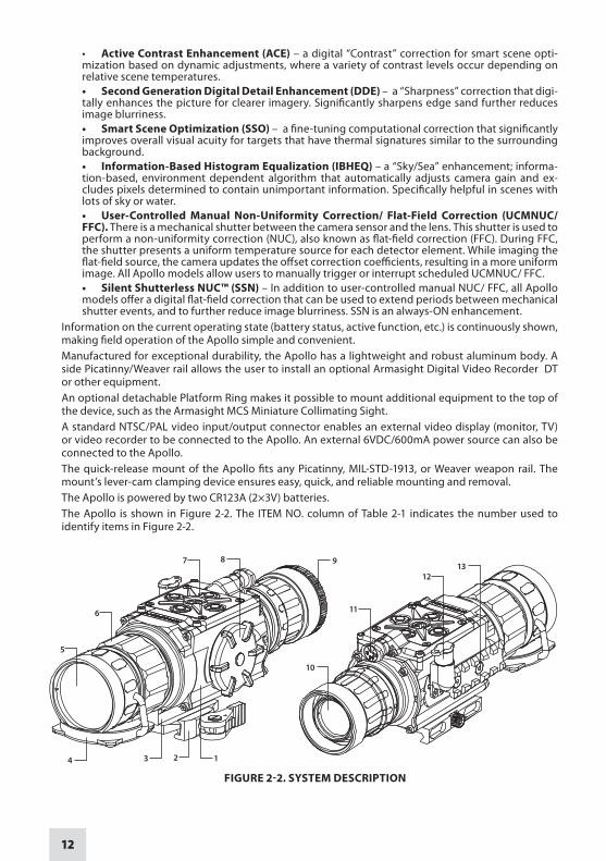
Information on the current operating state (battery status, active function, etc.) is continuously shown, making field operation of the Apollo simple and convenient.Manufactured for exceptional durability, the Apollo has a lightweight and robust aluminum body. A side Picatinny/Weaver rail allows the user to install an optional Armasight Digital Video Recorder DT or other equipment.An optional detachable Platform Ring makes it possible to mount additional equipment to the top of the device, such as the Armasight MCS Miniature Collimating Sight.A standard NTSC/PAL video input/output connector enables an external video display (monitor, TV) or video recorder to be connected to the Apollo. An external 6VDC/600mA power source can also be connected to the Apollo.The quick-release mount of the Apollo fits any Picatinny, MIL-STD-1913, or Weaver weapon rail. The mount’s lever-cam clamping device ensures easy, quick, and reliable mounting and removal.The Apollo is powered by two CR123A (2×3V) batteries.The Apollo is shown in Figure 2-2. The ITEM NO. column of Table 2-1 indicates the number used to identify items in Figure 2-2.
FIGURE 2-2. SYSTEM DESCRIPTION
1234
5
7 8
10
9
11
1312
6

13
TABLE 2-1. SYSTEM DESCRIPTION
ITEM DESCRIPTION ITEM DESCRIPTION
1 Body 8 Battery Cap
2 Mount 9 Output Lens Cap
3 Riser 10 Output Lens
4 Objective Lens Cap 11 Turn-pull Switch
5 Objective Lens 12 Connector (closed with a Cap)
6 Focus Ring 13 Side Picatinny/Weaver Rail
7 Button Control Panel
2.2 SPECIFICATIONS
TABLE 2-2. SYSTEM DATA
ITEM APOLLO 324 APOLLO 640
Magnification Unity (1x)Objective Lens Type GermaniumType of Focal Plane Array FLIR Tau 2Frame Rate 30 Hz or 60 HzPixel Array Format 324×256 640×512Pixel Size 25 µm 17 µmDisplay Type AMOLED SVGA 060Pixel Display Format 800×600Display Brightness Discretely Adjustable to 8 LevelsTurn-on Time, max 3 secTemperature Imaging Modes (Image Palettes)
White Hot, Black Hot, Fusion, Rainbow, Globow, Ironbow 1, Ironbow 2, Sepia, Color 1, Color 2, Ice-Fire, Rain, and OEM Custom
User-adjustable Image Enhancement Tools
Active Contrast Enhancement (ACE) - “CONTRAST”•Second Generation Digital Detail Enhancement (DDE) – “SHARPNESS”•
Smart Scene Optimization (SSO) – “SMART SCENE”•Information-Based Histogram Equalization (IBHEQ) – “SKY/SEA”•
User-Controlled Manual Non-Uniformity Correction/ Flat-Field Correction •(UCMNUC/ FFC)
Silent Shutterless NUC™ (SSN)•Bore- sighting
Accuracy Factory aligned to 1 MOA or betterRetention Permanent to within 2 MOA or betterRepeatability Within 2 MOA
Analog Input/Output Format (Resolution)
NTSC*(640×480 pixels) / PAL (768×574 pixels)
* Default setting

14
TABLE 2-3. OPTICAL DATA
ITEM APOLLO 324 APOLLO 640
Field of View
- ang. X degrees 11 15- ang. Y degrees 9 12
Objective Focal Length 42mmObjective F-number 1:1Exit Pupil Diameter 25mmFocus Method ManualFocusing Range 5m to inf.
TABLE 2-4. ELECTRICAL DATA
ITEM DATA
Battery Two CR123A 3V Lithium batteries or CR123 type rechargeable batteries with voltage from 3.0V to 3.7V (2)*
Current Consumption, maximum 320 mABattery Life at 20 °C (68 °F) Up to 4 hr (optional up to 12 hrs)
Extended Battery Pack Two 18650 rechargeable batteries (3.7V), or four CR123 type rechargeable batteries with voltage 3.7V max, or four standard CR123A 3V Lithium batteries (operational time up to 8 hr)
External Power Supply 6 VDC/ 600mА* Rechargeable batteries with voltage 3.0V-3.7V can be used only in devices with serial number starting from 140885
TABLE 2-5. MECHANICAL DATA
ITEM DATA
Weapon Mount Type Picatinny MIL-STD-1913 and Weaver RailsOverall Dimensions 217×70×80mm / (8.5”×2.8”×3.2“)
Height of the Scope Axis above Rail 40mm (1.57 in)Weight (w/o Batteries) 0.7 kg (1.5 lbs)
TABLE 2-6. ENVIRONMENTAL DATA
ITEM DATA
Operating Temperature -40 to +50°C (-40 to +122°F)Storage Temperature -50 to +70°C (-58 to +158°F)Recoil Resistance 700 gEnvironmental Rating Water and Fog-Resistant
TABLE 2-7. ADVANCED WIRELESS REMOTE CONTROL (AWREC) DATA
ITEM DATA
Type Wireless Remote ControlWorking Range up to 0.5mBattery Single CR2032 Lithium battery (3V) Battery Life at 20 °C (68 °F) Approx. 10,000 clicksOverall Dimensions 48×39×18mm (1.9”×1.5”×0.7”) Weight (with Battery) 25 g (0.9 oz)Operating Temperature -30 to +50°С (-22 to 122°F)Storage Temperature -50 to +70°С (-58 to 158°F)Environmental Rating Water and Fog-Resistant

15
TABLE 2-8. SCOPE MOUNTING SYSTEMS DATASCOPE
MOUNTING SYSTEM
WEIGHT, G
OVERALL DIMENSIONS,
MM
DIAMETER OF THE INSERTS,
MM
CLEAR APERTURE OF DAY SCOPE
LENS, MMEXAMPLE OF THE SCOPES
Scope Mounting System 1
53 39.5×43×52.425,4
20; 24Leupold 1.5-5x20 PR
30,0 Leupold 1.5-5x20 MR/T M2; Zeiss 1.1-4x24T
Scope Mounting System 2 61 44×49×62
38,0
32; 36
Meopta Artemis 2000 4x32
42,0Leupold Mark 4 3-9x36;
Leupold Mark 4 2.5-8x36; Kahles 4x36
Scope Mounting System 3
71 44×57.5×71
46,7
40; 42
Leupold 3.5-10x40; Leupold VX-II 3-9x40
48,0 Zeiss 1.5-6x42; Swarovski PV-N 2.5-10x42
48,7-49,0 Meopta Artemis 3000 3-9x42 49,5 Meopta Artemis 3000 4-12x4050,0 Schmidt&Bender 10x42
Scope Mounting System 4 82 44x65.5x79
56,0
50
Zeiss 2.5 10x5057,0 Schmidt&Bender 3-12x50
58,7 Leupold 4.4-14x50; Leupold VX-III 3.5-10x50
Scope Mounting System 6
93 44x70.5x84 62,0 56Zeiss 3-12x56;
Swarovski 2.5-10x56; Kahles CSX 3-12x56
2.3 STANDARD COMPONENTS
The Apollo standard components are shown in Figure 2-3 and listed in Table 2-8.The ITEM NO. column indicates the number used to identify items in Figure 2-3.
FIGURE 2-3. STANDARD COMPONENTS
15
1
2
3
4
13
7
9 10
12
11
16
65 8
14

16
TABLE 2-9. STANDARD COMPONENTS
ITEM NO. DESCRIPTION qUANTITY
1 ArmasightApolloThermalImagingClip-OnsystemA thermal imaging device. Comes fully assembled with a quick-release Picatinny/Weaver mount.
1
2 Objective Lens CapSecurely protects the objective lens from dirt and mechanical damage, and provides thermal protection for the Apollo. Comes attached to the objective lens.
1
3 Output Lens CapSecurely protects the output lens from dirt and mechanical damage.
1
4 MountA quick-release mount used to install the Apollo on a Picatinny/Weaver rail. Comes attached to the Apollo.
1
5 Battery CassetteIntended for the installation of two CR123 batteries in the battery compartment. The Apollo comes with two battery cassettes (includes one installed in the battery com-partment and one spare cassette).
2
6 CR123A Lithium BatteryTwo CR123A batteries are used to power the Apollo.
2
7 Advanced Wireless Remote Control (AWREC)Allows the user to operate the Apollo in short-time activation mode. Ensures quick and silent activation/deactivation of the equipment. Comes with CR2032 (3V) battery installed.
1
8 Picatinny Adapter for Advanced Wireless Remote ControlAllows the advanced wireless remote control to be installed on a weapon’s Picatinny/Weaver rail.
1
9 Light Suppressor 1A rubber cup mounted to the Apollo output lens to reduce light scattering. Used when installing the Apollo in front of day scopes with lens housing outer diameters of 25.4 to 42 mm.
1
10 Light Suppressor 2A rubber cup mounted to the Apollo output lens to reduce light scattering. Used when installing the Apollo in front of an ACOG 4×32 scope.
1
11 Light Suppressor 3A rubber cup mounted to the Apollo output lens to reduce light scattering. Used when installing the Apollo in front of day scopes with lens housing outer diameters of 47 to 50mm.
1
12 Light Suppressor for Day ScopeA rubber cup mounted to the day scope output lens to reduce light scattering and prevent surrounding light from interfering with the image.
1
13 Video CableA cable used to connect the analog video input/output of the Apollo to external dis-play devices (monitor, TV) or power sources. Supported input and output video formats include PAL and NTSC.
1
14 Operation and Maintenance ManualProvides safety information, equipment description, mounting procedures, operating instructions, and preventive maintenance checks and services.
1
15 Carrying CaseA textile bag used for the transportation and storage of the Apollo and its accessories.
1
16 HardShipping/StorageCaseA protective case used for the shipping/storage of the Apollo and its accessories.
1

17
2.4 OPTIONAL EqUIPMENT
Optional items are shown in Figure 2-4 and listed in Table 2-9.
4
7
6
5
8
9
1 2
FIGURE 2-4. OPTIONAL EqUIPMENT
3
The ITEM NO. column indicates the number used to identify items in Figure 2-4.The PART NO. column indicates the primary number used by the manufacturer, to identify an item.
TABLE 2-10. OPTIONAL EqUIPMENT
ITEM NO. DESCRIPTION PART NO.
1 Scope Mounting System 1 #40 A mounting system used to install the Apollo on the lenses of specified day scopes. Includes a clamp with inserts that will fit 25.4 and 30mm diameters.
ANAM000009
- Scope Mounting System 2 #41 A mounting system used to install the Apollo on the lenses of specified day scopes. Includes a clamp with inserts that will fit 38 and 42mm diameters.
ANAM000010
- Scope Mounting System 3 #42 A mounting system used to install the Apollo on the lenses of specified day scopes. Includes a clamp with inserts for 46.7, 48, 48.7-49, 49.5, and 50mm fitting diameters.
ANAM000011
- Scope Mounting System 4 #43 A mounting system used to install the Apollo on the lenses of specified day scopes. Includes a clamp with inserts for 56, 57, and 58.7mm fitting diameters.
ANAM000012
- Scope Mounting System 6 #44 A mounting system used to install the Apollo on the lenses of specified day scopes. Includes a clamp with inserts for 62mm fitting diameter.
ANAM000013
2 Extended Rail Adapter #85 A mounting system used to install a day scope behind the Apollo ona weapon, using a short-mounting Picatinny/ Weaver rail.
ANAM000045
3 FSRS Front Scope Rail System #38 A mounting system used to install a day scope behind the Apollo ona weapon, using a short-mounting Picatinny/ Weaver rail.
ANAM000021
4 3x Magnifier Converts the Apollo into 3x thermal imaging device for long-range observa-tion.
ANLE3X0008
18
ITEM NO. DESCRIPTION PART NO.
5 Platform RingA dedicated mount with a Picatinny/Weaver type rail used to install on the top of the Apollo an additional equipment, such as the Armasight MCS Miniature Collimating Sight.
ANLE3X0008
6 HD DVR Digital Video RecorderHigh Definition Digital Recorder for all Armasight High Performance Digital and Thermal Devices.
ATAM000005
7 DT Digital Video RecorderA compact digital system used for video recording, storage and playback. Can also serve as an external power source. Equipped with a remote control.
ATAM000004
8 Extended Battery Pack The power source for extended operational time. Takes four CR123A Lithium batteries (3V) or CR123 type rechargeable batteries (3.2V or 3.7V) or two 18650 type rechargeable batteries (3.7V).
ATAM000008
9 AMRF2200 Advanced Modular Range FinderThe modular range finder is designed to determine the exact distance be-tween the observer and the target. Measurement results are shown on both the module display and in the field of view of the connected digital device.
IALA00AMRF22001
2.5 KEY FEATURES
Converts your day scope, sight, or binoculars into thermal imaging device – Mounts in front of any day scope with no re-zeroing required – High-performance thermal imaging camera – Lightweight and robust design – Easy to operate – Manually adjustable objective lens – Real-time display – Digitally controlled features: – • Palette• Enhancement• Settings• Display Brightness• User-Controlled Manual Non-Uniformity Correction/ Flat-Field Correction (UCMNUC/ FFC)
Current operational state information display (battery status, active profile, palette setting) – Wireless remote control – Analog video input and output (NTSC/PAL) – Powered by two standard CR123A batteries. – Power input capability – Digital video recorder (optional) – Fits any Picatinny, MIL-STD-1913, or Weaver rail with an adjustable quick-release mount – Serviceability under severe conditions – Filled with dry nitrogen to prevent internal fogging – Water and fog-resistant – Limited 3-year warranty – 10-year warranty on FLIR detector –
TABLE 2-10. CONTINUED

19
3OPERATING INSTRUCTIONS
3.1 INSTALLATION AND MOUNTING
3.1.1 BATTERY INSTALLATION
CAUTION:Verify that the equipment is off before installing a battery.
Install two CR123A batteries as follows (refer to Figure 3-1):1. Unscrew the battery cap (A).2. Remove the battery cassette (B).3. Insert the batteries (C) into the cassette. Align the polarity symbols on the batteries with the polarity
symbols on the cassette.4. Reinsert the cassette with installed batteries.5. Replace the battery cap.
3.1.2 INSTAllINGTHEApOllOONApICATINNy/WEAvErrAIl
WARNING:Always make sure your firearm is unloaded before you place the scope on the firearm. Always verify that the chamber is empty, especially if you stop the procedure and resume later. Safe handling rules should be followed at all times.
FIGURE 3-1. BATTERY INSTALLATION
A
BC
20
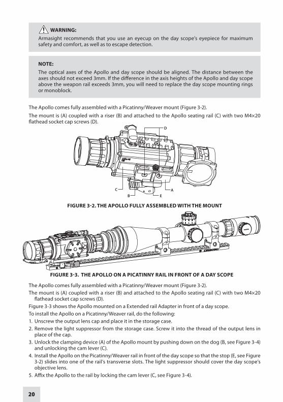
WARNING:Armasight recommends that you use an eyecup on the day scope’s eyepiece for maximum safety and comfort, as well as to escape detection.
NOTE:The optical axes of the Apollo and day scope should be aligned. The distance between the axes should not exceed 3mm. If the difference in the axis heights of the Apollo and day scope above the weapon rail exceeds 3mm, you will need to replace the day scope mounting rings or monoblock.
The Apollo comes fully assembled with a Picatinny/Weaver mount (Figure 3-2).
The mount is (A) coupled with a riser (B) and attached to the Apollo seating rail (C) with two M4×20 flathead socket cap screws (D).
AB E
C
D
FIGURE 3-2. THE APOLLO FULLY ASSEMBLED WITH THE MOUNT
The Apollo comes fully assembled with a Picatinny/Weaver mount (Figure 3-2).The mount is (A) coupled with a riser (B) and attached to the Apollo seating rail (C) with two M4×20
flathead socket cap screws (D).Figure 3-3 shows the Apollo mounted on a Extended rail Adapter in front of a day scope.To install the Apollo on a Picatinny/Weaver rail, do the following:1. Unscrew the output lens cap and place it in the storage case.2. Remove the light suppressor from the storage case. Screw it into the thread of the output lens in
place of the cap.3. Unlock the clamping device (A) of the Apollo mount by pushing down on the dog (B, see Figure 3-4)
and unlocking the cam lever (C).4. Install the Apollo on the Picatinny/Weaver rail in front of the day scope so that the stop (E, see Figure
3-2) slides into one of the rail’s transverse slots. The light suppressor should cover the day scope’s objective lens.
5. Affix the Apollo to the rail by locking the cam lever (C, see Figure 3-4).
FIGURE 3-3. THE APOLLO ON A PICATINNY RAIL IN FRONT OF A DAY SCOPE

21
6. Verify that the clamping device is firmly secured to the Apollo. If necessary, adjust the clamping device as detailed in Part 3.1.3 (Clamping Device Adjustment).
3.1.3 CLAMPING DEVICE ADjUSTMENTTo adjust the mount’s clamping device, do the following (refer to Figure 3-5):1. Unlock the clamping device and remove the Apollo from the weapon.2. To tighten/loosen the clamping device (B), push the cam (C) towards the arrow, which will cause the
nut (A) to slide out of its hole. Turn the nut (A) CW/CCW respectively, in one-two increments (see note below). Backward-moving springs will cause the nut (A) to slide back into the hole.
NOTE:The eight-sided nut of the clamping device will only fit into the hole if turned in one of the discrete positions using increments equal to 360°/8.
3. Verify that the adjusted clamping device is firmly secured to the Apollo.
3.1.4 INSTALLING THE APOLLO ON A WEAPON USING THE OPTIONAL FSRS SYSTEM
The FSRS system is delivered ready-assembled. The components of the FSRS system are shown in Fig-ure 3-6.
A. Dismantling the FSRS System
Dismantle the FSRS system as follows (see Figure 3-6):1. Unlock the clamping device (D) and remove the extension mount (E) from the bridge (B).2. Unscrew the screws (C) and remove the bridge (B) from the mount (H).3. Unscrew the screws (F) and remove the clamps (G).
B. Mounting the Day Scope
Figure 3-7 shows the day scope mounted to the FSRS system.
Mount the day scope to the FSRS system as follows:
FIGURE 3-4. MOUNT. TOP VIEW
CBLOCKED POSITION UNLOCK POSITION
A
FIGURE 3-5. MOUNT. UNDERSIDE VIEW
LOCKED POSITION UNLOCK POSITION
A
BC

22
FIGURE 3-6. OPTIONAL FSRS SYSTEM. COMPONENT PARTS
E
F
B
A
D
C
J
GI
H
1. Loosen the nuts (A, Figure 3-6). Install the mount (H) on the weapon’s Picatinny/ Weaver rail. The two pins of the mount’s clamping device should be secured in the transverse slots of the rail. Manually retighten the nuts (A).
NOTE:Pay attention to the arrow engraved on the right side of the mount (H).The arrow must be pointed towards the end of the weapon muzzle.
FIGURE 3-7. DAY SCOPE MOUNTED ON FSRS SYSTEM
2. Without tightening the screws (F), use the clamps (G) to fasten the scope into the mount (H) with a 34mm diameter, as seen in the preassembled equipment. To mount day scopes with diameters of 30mm or 25.4mm, use the corresponding inserts (J).
3. Adjust or reposition the mount (H) along the weapon rail until you find the most comfortable posi-tion over your eye. Readjust until the cross-hairs are level, and are not tilted. After positioning the scope in the mount (H), apply a small amount of thread lock to the threads, and tighten the screws (F) using a 3mm hex key.
4. Tighten the nuts (A) with a screwdriver to secure the mount (H) to the weapon rail.

23
C. Mounting the Apollo and Additional Equipment
Figure 3-8 shows the Apollo and day scope mounted to the FSRS system.
Mount the Apollo and additional equipment to the FSRS system as follows:1. Install the bridge (B, Figure 3-6) on the bushes (I, Figure 3-6). After applying a small amount of thread
lock to the threads, install and tighten the screws (C, Figure 3-6) using a 3mm hex key.2. Unlock the clamping devices (D, Figure 3-6). Install the extension mount (E, Figure 3-6) onto the
Weaver rail of the bridge (B). Verify that the clamping device is secured to the extension mount. If necessary, adjust the clamping device as detailed in Part 3.1.3.
3. Install the Apollo (A, Figure 3-8) onto the Weaver rail (B), underneath the extension mount, as shown in Part 3.1.3.
4. Affix additional equipment to the mount’s top Weaver rail (C, Figure 3-8).
After you have completed these steps, remounting the equipment without reinstalling the mount only requires that you remove the extension mount (with the equipment installed) from the bridge.
3.1.5 INSTALLING THE APOLLO ON THE LENS OF A DAY SCOPEUse the optional Scope Mounting System (SMS) to install the Apollo onto day scope lenses.
NOTE:The adapters differ in attaching diameters and must fit with the day scope parameters specified in Table 2-7 (Scope Mounting Systems Data).
NOTE:The Apollo cannot be attached to scopes that include focus rings on the housing of the objec-tive lens.
CAUTION:Scope Mounting Systems are not recommended for installing the Apollo on firearms with dy-namic recoil (0.308 Win or stronger).
BA
C
FIGURE 3-8. APOLLO AND DAY SCOPE MOUNTED ON FSRS SYSTEM
FIGURE 3-9. THE APOLLO INSTALLED ON THE LENS OF A DAY SCOPE
24
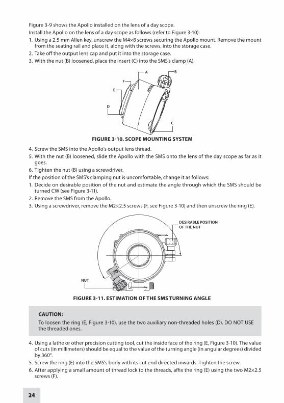
Figure 3-9 shows the Apollo installed on the lens of a day scope.Install the Apollo on the lens of a day scope as follows (refer to Figure 3-10):1. Using a 2.5 mm Allen key, unscrew the М4×8 screws securing the Apollo mount. Remove the mount
from the seating rail and place it, along with the screws, into the storage case.2. Take off the output lens cap and put it into the storage case.3. With the nut (B) loosened, place the insert (C) into the SMS’s clamp (A).
4. Screw the SMS into the Apollo’s output lens thread.5. With the nut (B) loosened, slide the Apollo with the SMS onto the lens of the day scope as far as it
goes.6. Tighten the nut (B) using a screwdriver.If the position of the SMS’s clamping nut is uncomfortable, change it as follows:1. Decide on desirable position of the nut and estimate the angle through which the SMS should be
turned CW (see Figure 3-11).2. Remove the SMS from the Apollo.3. Using a screwdriver, remove the M2×2.5 screws (F, see Figure 3-10) and then unscrew the ring (E).
FIGURE 3-11. ESTIMATION OF THE SMS TURNING ANGLE
NUT
DESIRABLE POSITION OF THE NUT
CAUTION:To loosen the ring (E, Figure 3-10), use the two auxiliary non-threaded holes (D). DO NOT USE the threaded ones.
4. Using a lathe or other precision cutting tool, cut the inside face of the ring (E, Figure 3-10). The value of cuts (in millimeters) should be equal to the value of the turning angle (in angular degrees) divided by 360°.
5. Screw the ring (E) into the SMS’s body with its cut end directed inwards. Tighten the screw.6. After applying a small amount of thread lock to the threads, affix the ring (E) using the two M2×2.5
screws (F).
FIGURE 3-10. SCOPE MOUNTING SYSTEM
A
F
E
D
B
C

25
3.1.6 INSTALLING THE LIGHT SUPPRESSOR FOR A DAY SCOPEThe Light Suppressor for a Day Scope (A, Figure 3-12) slides over the eyepiece of your daytime scope (B). The suppressor can be used with scopes that have 40-43mm eyepiece diameters and 100-120 mm eye relief.
The suppressor can be adjusted for the eye relief of your scope by cutting the rubber at the desired distance (C).
3.1.7 MOUNTING A PLATFORM RINGMount the Platform Ring (optional) on the Apollo as follows (refer to Figure 3-13):1. Using a 1.5 hex key, unscrew both clamp screws (C).2. Place the clamps (B, D) onto the mounting tube. Screw the clamps together without tightening the
screws (C).3. Adjust the position of the Platform Ring until its rail (A) is level. Apply a small amount of thread lock
to the threads and tighten the screws (C).
3.1.8 FASTENING AN ADVANCED WIRELESS REMOTE CONTROL TO A WEAPON
Using Velcro tape (A, Figure 3-14), fasten the remote control (B) to your weapon in an easily accessible place (e.g., on the front of the rifle stock).
If your rifle has a Picatinny or Weaver rail on the front end, you can use the Picatinny adaptor for the Advanced Wireless Remote (C). Install the adaptor onto the rail (D). Insert the remote control unit into the adapter.
FIGURE 3-12. LIGHT SUPPRESSOR FOR A DAY SCOPE
CB A
FIGURE 3-13. PLATFORM RING
A
B
C
C
D
A
FIGURE 3-14. ADVANCED WIRELESS REMOTE CONTROL
A
B
B
C
D

26
3.1.9 INSTALLING ADDITIONAL EqUIPMENTUse the side Picatinny/Weaver rail to install any additional equipment, such as the Armasight DT Digital Video Recorder, a range finder, or the Extended Battery Pack.
Use a Platform Ring (optional) to install any additional equipment, such as the Armasight MCS Minia-ture Collimating Sight. For adapter mounting procedures, see Part 3.1.4.
3.1.10 CONNECTING AN ADDITIONAL EqUIPMENT
CAUTION:Turn off the Apollo before removing the batteries or connecting/disconnecting any external equipment.
Remove the connector protective cap.Connect a cable of Armasight DT digital video recorder or the Extended Battery Pack to the Apollo connector.
Use the video cable plug (A, Figure 3-16) to connect an external video recorder/monitor/TV to the Apol-lo. Connect the video cable plug (C) to the Apollo connector.
Use the video cable plug (B) to connect an external power source (6VDC/ 600mA) to the Apollo. Con-nect the video cable plug (C) to the Apollo connector.
AB
FIGURE 3-16. VIDEO CABLE
C
NOTE:The external power supply must have a standard OD double-pole socket with a positive center contact.
CAUTION:After removing the cable, replace the protective cap over the connector.
FIGURE 3-15. ARMASIGHT DIGITAL RECORDER DT INSTALLATION

27
3.1.11 INSTALLING THE 3X MAGNIFIERFigure 3-17 shows the Apollo with the3x magnifier installed.
To install the 3x magnifier on the Apollo, do the following:1. Take off the output lens cap and place it into the storage case.2. Screw the 3x magnifier into the Apollo’s output lens thread.
3.2 CONTROLS AND DISPLAY INDICATIONS
3.2.1 CONTROLS
CAUTION:DO NOT force the equipment controls past their stopping points.
The Apollo controls are shown in Figures 3-18 and 3-19, and are defined in Tables 3-1 and 3-2. The ITEM NO. columns indicate the numbers used to identify items in the figures.
NOTE:Various display symbols indicating the current operating state of the Apollo can be displayed permanently, may appear momentarily, or can be set to appear only when a certain function is activated.
FIGURE 3-17. THE APOLLO WITH A 3X MAGNIFIER
1
23
4
FIGURE 3-18. CONTROLS

28
TABLE 3-1. CONTROLS AND INDICATORS
ITEM NO. CONTrOl/INDICATOr FUNCTION
1 Turn-pull Switch Activates the Apollo when turned to ON.NOTE:You must pull the knob before turning in order to use either ON or STB.
Activates standby mode when turned to STB (see note above).
Deactivates the Apollo when turned to OFF.
2 Control Panel Buttons Configures operational settings. See Table 3-2 for button functions.
3 Objective Focus Ring Focuses the objective lens. Adjusts for sharpest view of the scene. The total focus range is covered with three quarter turns of the lens.
4 Remote Control Button
Activates/deactivates the Apollo in standby mode. To turn the unit on, press the button once. To turn it off, press the button again.
— Battery Status Indicator(a battery icon in the top right hand corner of the display)
The color fill (green/yellow/red) bar in the battery icon indicates the current power level of the internal battery, or the remaining battery life.
A shaded battery icon indicates a fully charged battery.
A flashing, transparent battery icon indicates a low battery.
The Apollo button control panel is shown in Figures 3-19. Table 3-2 contains the button functions and their brief descriptions. The ITEM NO. column of the table indicates the number used to identify buttons in Figure 3-19.
NOTE:Each button is responsible for some functions selected by briefly pushing or holding down the button, or using the button in combination with a second one (as described in Table 3-2).Pushing a button for 1.5+ seconds is considered “holding down.”
1
3
4
5
2
FIGURE 3-19. BUTTON CONTROL PANEL

29
TABLE 3-2. BUTTON CONTROLS
ITEM NO. FUNCTION DESCRIPTION
1, 3
DISPLAY BRIGHTNESS CONTROL
Push the button (1) to increase the screen brightness or push the button (3) to decrease the screen brightness.
IMAGE PALETTE CONTROL
To search available palettes, push and hold the button (1) or (3) to scroll down or up respectively. There are 13 palettes available: White Hot, Black Hot, Fusion, Rainbow, Globow, Ironbow1, Iron-bow2, Sepia, Color1, Color2, Ice-Fire, Rain, and OEM.Simultaneously holding down buttons (1) and (3) induces manual User-Controlled Manual Non-Uniformity Correction/ Flat-Field Correction (UCMNUC/ FFC).Use the UP (1) and DOWN (3) buttons to navigate through the items on the menu.
USER CONTROLLED MANUAL NON UNIFORMITY CORREC-TION/FLAT-FIELD CORREC-TION (UCMNUC/FFC)
Simultaneously holding down buttons (1) and (3) induces manual User-Controlled Manual Non-Uniformity Correction/ Flat-Field Correction (UCMNUC/ FFC).
UP, DOWN Use the UP (1) and DOWN (3) buttons to navigate through the items on the menu.
2DIGITAL ZOOM CONTROL To change the zoom progressively, push the button (2). Digital
Zoom is not used in clip-on mode.
RETICLE ON/ OFF * Pushing and holding the button (2) turns the reticle ON or OFF. Reticle is not used in clip-on mode.
4
RETICLE COLOR CONTROLTo change the reticle color, push the button (4). There are four colors available: black, white, red, and cyan. Not used in clip-on mode.
RETICLE PATTERN CONTROL
To scroll through the reticle types, push and hold the button (4). There are five types of reticles available: Dot 4 MOA, Line Dot, Cross Center Dot, Cross, and Crosshair. Not used in clip-on mode.
2, 4RETICLE POSITION ZEROING
Simultaneously holding down buttons (2) and (4) zeroes the reticle position to the center of the screen. Not used in clip-on mode.
LEFT, RIGHT Use the LEFT (4) and RIGHT (2) buttons to navigate through the items on the menu.
5
SELECTION Push the SELECTION button (5) to view the settings available for the item selected.
MAIN MENU Pushing and holding the button (5) will bring up the Main Menu selection. The menu includes the following functions: Palette, Reticle, Boresight, Enhancement, and Settings.
UCMNUC/ FFC PROCESS INTERRUPTION
Pushing the button (5) when the countdown is on the screen will cancel the UCMNUC/ FFC, and the shutter will not interrupt viewing.
*The Reticle function can be activated, for example, when the Apollo is used in conjunction with 3x Magnifier. *The Reticle Color, Reticle Pattern, Reticle Position controls are available when the Reticle is activated.
3.2.2 MAIN MENUMost setup options can be accessed from the MAIN MENU.
To display the MAIN MENU, push and hold down the MENU button (5) on the control panel (Figure 3-20).
Once the MAIN MENU is displayed (Figure 3-21), use the UP and DOWN buttons (Figure 3-20) to navigate through the items on the menu.
Push the SELECTION button to view the settings available for the item selected.

30
NOTES:Navigate through sub-menu items by pushing UP and DOWN, except where otherwise indi-cated. The LEFT and RIGHT buttons are available only when specified on the menu screen with <> symbols.After a menu item is selected, push the SELECTION button to make the selected setting/ acti-vate the selected function.Select the EXIT item and then push the SELECTION button to return to the MAIN MENU.
(1) UP
(3) DOWN
(4) LEFT
(5) SELECTION
(2) RIGHT
FIGURE 3-20. MAIN MENU NAVIGATION BUTTONS
Palette Menu
The PALETTE menu (Figures 3-22 and 3-23) allows the user to select from a choice of temperature im-aging modes: White Hot, Black Hot, Fusion, Rainbow, Globow, Ironbow 1, Ironbow 2, Sepia, Color 1, Color 2, Ice-Fire, Rain, and OEM Custom.
NOTE:To navigate through the items on the two-page PALETTE menu, hold down the UP(1)/ DOWN (3) button.
The palettes act as color templates for visualizing temperature changes in the scene.
NOTE:The most popular palettes are White Hot and Black Hot, usually known as inversion. White Hot mode is good for spotting targets, while Black Hot mode is most useful for situational reading.
> EXIT PALETTE RETICLE BORESIGHT ENHANCEMENT SETTINGS
MAIN MENU
FIGURE 3-21. MAIN MENU

31
NOTE:Training and experience are required to quickly and properly interpret the thermal image being displayed.
Reticle Menu The RETICLE menu (Figure 3-24) allows the user to select from a choice of reticle patterns: Dot Type, Line Dot, Crosshair Center Dot, and Crosshair.To navigate through the items on the RETICLE menu, push and hold down the LEFT button (4).
> EXIT
<> CROSS
RETICLE
FIGURE 3-24. RETICLE MENU
Boresight Menu The BORESIGHT function allows the user to change the position of the reticle in the display.
NOTE:Remember that the center of impact on the target shifts in the opposite direction from the direction that the reticle shifts. So, to bring the center of impact to the right/left and up/down, you must shift the reticle to the left/right and down/up, respectively.
> EXIT WHITE HOT BLACK HOT FUSION RAINBOW GLOBOW IRONBOW1 IRONBOW2
PALETTE
FIGURE 3-22. PALETTE MENU. PAGE 1
> EXIT SEPIA COLOR 1 COLOR 2 ICE - FIRE RAIN OEM CUSTOM
PALETTE
FIGURE 3-23. PALETTE MENU. PAGE 2

32
Figure 3-25 shows the boresight screen.
> EXIT
WINDAGE <> 40 ELEVATION <> -5
BORESIGHT
FIGURE 3-25. BORESIGHT MENU
To control reticle shifting, check the running reticle center coordinates, which are printed in the lower left hand corner of the display.
NOTE:For display coordinates, the origin is the center of the display. The running coordinate of the ret-icle is the number of incremental shifts of the reticle from the center of the display. The negative (-) sign appears before the displayed number when the reticle shifts left or down. The point of impact (POI) on the target shifts right or up, respectively).
Push the LEFT and RIGHT buttons to adjust for windage. Moving the reticle in the positive (+) direction (to the right) will move the POI to the left. Moving the reticle in the negative (-) direction (to the left) will move the POI to the right.
Push the UP and DOWN buttons to adjust for elevation. Moving the reticle in the positive (+) direction (up) will move the POI down. Moving the reticle in the negative (-) direction (down) will move the POI up.
Every time one of these buttons is pushed, the reticle shifts a single pixel increment corresponding to the minimum boresight correction value, and the point of impact on the target moves according to the specified windage/elevation boresight increment, in the opposite direction to that of the shifting reticle.
Every time one of these buttons is pushed for 3 sec, the reticle will shift in increments of 4 pixels until you release the button.
Hold down both the LEFT and RIGHT buttons to reset to zero azimuth and elevation. The reticle will shift to the display center.
Enhancement MenuThe ENHANCEMENT menu (Figure 3-26) allows the user to take advantage of advanced signal process-ing algorithms, in order to improve the quality of the picture that is being viewed under a variety of different thermal environments.
> EXIT CONTRAST SHARPNESS SMART SCENE SKY/SEA
ENHANCEMENT
FIGURE 3-26. ENHANCEMENT MENU

33
CONTRAST - Active Contrast Enhancement (ACE) – a digital contrast correction that allows for a smart scene optimization based on dynamic adjustments where a variety of contrast levels occur depending on relative scene temperatures. The adjustment range is from -8 to +8 with a default value of 0. Lower values will cause hotter objects to get more contrast, while higher values will cause colder objects get more contrast.
SHARPNESS - Second Generation Digital Detail Enhancement (DDE) – a sharpness correction that digi-tally enhances the picture for clearer imagery, significantly sharper edges, and reduced image blurri-ness. The adjustment range is from -20 to +100 with a default value of 16. Lower volumes will soften the edges of the image. Higher values will sharpen objects, enhance details, and further increase the signal to noise ratio.
SMART SCENE - Smart Scene Optimization (SSO) – a fine-tuning computational correction that signifi-cantly improves overall visual acuity for targets that have thermal signatures similar to the surrounding background. Higher values provide more linear automatic gain control behavior. Objects with similar (but not identical) temperatures can be differentiated with greater accuracy. The adjustment range is from 0 to 100, with a default value of 100.
FIGURE 3-27. DIGITAL CONTRAST CORRECTIONCONTRAST -8 CONTRAST +8
FIGURE 3-28. SHARPNESS CORRECTIONSHARPNESS -20 SHARPNESS +100
FIGURE 3-29. SMART SCENE OPTIMIzATION SMART SCENE 0 SMART SCENE 100

34
SKY/SEA - Information-Based Histogram Equalization (IBHEQ) – a “Sky/Sea” enhancement – informa-tion-based, environment dependent algorithm that automatically adjusts camera gain and excludes pixels determined to contain unimportant information. This is specifically helpful in scenes with lots of sky or water. Turning the “Sky/Sea” enhancement ON will improve the contrast for the area of interest, but at the possible loss of some scene content.
Settings MenuThe SETTINGS menu (Figure 3-31) allows direct changes to the saved rifle profiles, video standards, left display margins, top display margins, and factory default settings.
The RIFLE PROFILE function allows the user to boresight the Apollo to the weapon, and then save the boresighted reticle position map in the “Rifle Profile” tab. This can be done for the same scope with up to 3 different rifles (Profile 1, Profile 2, and Profile 3).
The STANDARD function allows the user to select either the NTSC or PAL video standard.
The LEFT MARGIN function allows the user to move the display left/right by a fixed number of pixels.
The TOP MARGIN function allows to move the display up/down by a fixed number of pixels.
The FACTORY DEFAULTS function resets the Apollo to factory defaults.
The SETTINGS menu also includes factory software revision information under FW: (software version is shown in alpha-numeric format).
> EXIT RIFLE PROFILE STANDARD LEFT MARGIN TOP MARGIN FACTORY DEFAULTS FW: (factory software revision)
SETTING
FIGURE 3-31. SETTINGS MENU
NOTE:After configuration is complete, select EXIT on the MAIN MENU and push the SELECTION button to leave the MAIN MENU. All settings will be saved.
FIGUrE3-30.“Sky/SEA”ENHANCEMENT
SKy/SEE OFF - PLANE AND BANNER ARE MORE EvIDENT
SKy/SEE ON – MORE CONTRAST DEvOTED TO PEOPLE AND THE BOAT

35
3.3 OPERATING PROCEDURES
3.3.1 OPERATING
WARNING:Always make sure your firearm is unloaded before you place the scope on the firearm. Always verify that the chamber is empty, especially if you stop the procedure and resume later. Safe handling rules should be followed at all times.
CAUTION:DO NOT force the equipment controls past their stopping points.
CAUTION:To prevent thermal damage to the equipment, never point it (either ON or OFF) directly at the sun or any other source of high intensity light that the unprotected human eye cannot tolerate (such as a welding arc). To prevent accidental exposure to these sources, never leave the equip-ment around without first securing the objective lens cap.
Operating procedures are as follows:1. Remove the Apollo from the carrying case.2. Install the Apollo on the weapon with a day scope. Refer to Parts 3.1.2-3.1.5 for installation proce-
dures.3. Verify that the Apollo is securely mounted to the weapon or scope.4. Remove the protective caps.5. Point the equipment at an object.6. Activate the Apollo by turning the turn-pull switch ON. After approximately 3 sec, video of the ther-
mal scene should appear.7. If the day scope includes a focusing ring (i.e., parallax adjustment knob), adjust the focus for a paral-
lax-free image.8. Turn on the day scope’s reticle illumination and adjust the reticle brightness. 9. Adjust the focus of Apollo by turning the focus ring (CW for far focus, CCW for near focus).
NOTE:The total focus range is covered with 3/4 turns of the objective focus ring.
10. Using the buttons on the control panel (Figure 3-32), configure the Apollo for your specific situ-ation.For more information on operational setting procedures, see Part 3.2 (Controls and Display Indica-tions).A. Adjust the brightness of the display to your preferred level.Push the brightness adjustment buttons to increase (1)/decrease (3) the display brightness by one level at a time until you reach your desired brightness level.B. Use UCMNUC/ FFC (User-Controlled Manual Non-Uniformity Correction/ Flat-Field Correction) function to improve image quality. As the camera and the detector heat up during use, the detector pixels will drift. The pixels do not drift uniformly. The camera software compensates for the drift up to an accurate position point, but when the limit is reached the UCMNUC/ FFC function is triggered. A uniform mechanical shutter is placed between the lens and the detector for a moment and the signal is processed.

36
Push and hold the two brightness control buttons (1 and 3) at the same time to manually trigger the User-Controlled Manual Non-Uniformity Correction/ Flat-Field Correction. If necessary, interrupt the automatic UCMNUC/ FFC process by pushing the central button (5) on the control panel during the 5-second countdown, which will appear at the bottom of the display.
(1) BRIGHTNESS UP/PALETTE (FWD)
(3) BRIGHTNESS DOWN / PALETTE (BWD)
(4) RETICLE COLOR / RETICLE PATTERN
(2) DIGITAL ZOOM / RETICLE ON/ OFF
FIGURE 3-32. SETTING BUTTONS
C. Adjust as necessary using the MAIN MENU. See Part 3.2.2 (Using the MAIN MENU).
NOTE:After configuration is complete, select EXIT on the MAIN MENU and push the SELECTION button to leave the MAIN MENU. All settings will be saved.
11. To align the barrel of the weapon, place the reticle on the desired target. To allow for the bullet’s travel (i.e. bullet drop, windage, and the target mobility), adjust the boresight of the day scope.
12. To operate the Apollo in short-time activation mode, turn the switch to the STB position (standby). To activate the scope, press the remote control button once. Press the remote control button again to deactivate the scope.
CAUTION:DO NOT leave the equipment activated when not in use.
3.3.2 USING THE APOLLO WITH THE 3X MAGNIFIER
The 3x Magnifier converts the Apollo into a 3x thermal imaging device for long-range observation. The Apollo with the 3x Magnifier can also be used as a thermal imaging weapon sight. Use the Apollo with the 3x Magnifier in weapon sight mode as follows:
1. Install the 3x Magnifier on the Apollo. For mounting procedures, see Part 3.1.11.2. Install the Apollo with 3x Magnifier on a weapon.3. Turn on the Apollo. 4. Activate the Apollo reticle by pushing and holding the button (2).5. Adjust the brightness of the display. 6. Adjust the eyepiece of 3x Magnifier and focus the objective lens to sharpen the image of the target.7. Select a reticle pattern. To scroll through the reticle types, push and hold button (4). To change the
reticle color, push button (4).8. Use digital zoom to magnify the central area of the displayed scene. Push the zoom control button
(2) to slowly magnify into the displayed scene. The X1, X2, X4 symbols will appear in the lower part of the display.

37
NOTE:Digital zoom allows distant objects to appear larger; however, the resolution will be compro-mised.
NOTE:Zooming does not affect the boresight.
NOTE:Digital zoom and reticle color control help target detection and discrimination.
NOTE:The Apollo with the 3x Magnifier must be zeroed each time it is mounted to a new weapon.
Boresight the Apollo with the 3x Magnifier as follows:1. Set the Apollo in the correct profile that needs to be bore sighted. 2. Locate a target at the fire adjustment range (for example, 100yd or 100m).3. Turn on the Apollo.4. Adjust the Apollo, as shown above.5. Take aim by centering the reticle on the target and fire a series of shots (3-4).6. Find the point of impact and measure its vertical and horizontal deviations from the center of the
target.7. Work out the values of boresight correction required to compensate for the measured deviation of
the point of impact from the center of the target. Table 3-3 contains examples of calculating bore-sight correction values.
TABLE 3-3. EXAMPLE OF CALCULATING CORRECTIONS (100YD AND 100M FIRE RANGES)
MODEL APOLLO 324 APOLLO 640
Windage/ Elevation Boresight Increment * 0.71 MOA0.2 mils
0.7 in/100 yd2cm/100m
1.35 MOA0.4 mils
1.4 n/100 yd4cm/100m
Windage/ Elevation Adjustment Range * ±57 MOA / ±43 MOA ±108MOA / ±81 MOAMeasured Windage/ Elevation Deflection of the Point of Impact from the Target Center (EXAMPLE)
2in / 1in (5cm / 2cm)
5in / 10in(13cm / 25cm)
Correction Value
Windage 2/0.7≈3 shifts (5/2≈3 shifts)
5/1.4≈4 shifts (13/4≈3 shifts)
Elevation 1/0.7≈1 shift (2/1=1 shift)
10/1.4≈7 shifts (25/4≈6 shifts)
* 1) For NTSC resolution (640x480)2) To calculate boresight increment value for a fire range R different from 100 yards, use the coefficient R/100. At a range R (in yards) the boresight increment is:
0.7×R/100, in — for Apollo 336;1.35×R/100, in — for Apollo 640.

38
3) To calculate boresight increment value in metric units for a fire range R different from 100m, use the coefficient R/100. At a range R (in meters) the boresight increment is:
2×R/100, cm — for Apollo 336; 4×R/100, cm — for Apollo 640.
8. Use the BORESIGHT MENU to apply corrections required to bring the point of impact as close as pos-sible to the center of the target. See Part 3.2.2 (Using the MAIN MENU).
A. Use the LEFT and RIGHT buttons to adjust for windage. Moving the reticle in the positive (+) direc-tion (to the right) will move the point of impact to the left. Moving the reticle in the negative (-) direction (to the left) will move the point of impact to the right.
B. Use the UP and DOWN buttons to adjust for elevation. Moving the reticle in the positive (+) di-rection (up) will move the point of impact down. Moving the reticle in the negative (-) direction (down) will move the point of impact up
9. Fire a series of shots to check the boresight.10. After completing the boresight adjustment procedure, you can use RIFLE PROFILE function in the
Settings menu to save the boresighted reticle position in the “Rifle Profile” tab. This can be done for the same scope with to up to 3 different rifles (Profile 1, Profile 2, and Profile 3).
11. Turn the Apollo OFF and place the cap over the objective lens.
3.3.3 APOLLO SHUT-DOWN
NOTE:Shut down the Apollo to properly to avoid losing unsaved settings and data.
Shutdown the Apollo as follows:
1. Be sure to save your settings and data.
2. Turn off the Apollo.
3. Replace the cap on the objective lens.
4. Disconnect the cable (if applicable).
5. Place the cap on the connector.
6. Dismount the Apollo from the weapon.
7. Remove the batteries.
CAUTION:Do not store the Apollo with the batteries still installed.
8. Store the Apollo and all accessories in the carrying case.

39
4PREVENTIVE MAINTENANCE AND
TROUBLESHOOTING
4.1 PREVENTIVE MAINTENANCE CHECKS AND SERVICES
4.1.1 PREVENTIVE MAINTENANCE CHECKS AND SERVICES (PMCS)Table 4-1 Preventive Maintenance Checks and Services (PMCS), has been provided so that you can keep your equipment in good operating condition.
Perform functional tests in the order listed in Table 4-1.
Operating procedures are detailed in Chapter 3.
Explanation of Table Entries:SEq NO. column. Sequence numbers are for reference and appear in the order required to perform checks and services.
lOCATIONOF/ITEMTOCHECk/SErvICE column. Indicates the location and the item to be checked or serviced.
PROCEDURE column. Details the check/ service procedure.
NOT FULLY MISSION CAPABLE IF... column. Indicates what faults will prevent your equipment from operating successfully.
TABLE 4-1. PREVENTIVE MAINTENANCE CHECKS AND SERVICES
SEq NO.
LOCATION OF ITEM TOCHECk/SErvICE PROCEDURE NOT FULLY MISSION
CAPABLE IF...
BEFORE OPERATION CHECKS1 Completeness Open storage/carrying case and inventory items
by comparing them with the data specified in this manual.
Missing items.
2 Soft Carrying Case
Shake out loose dirt or foreign material. Inspect for tears, cuts, excess wear or damage.
3 Body Inspect for cracks or damage. Scratches and gouges are OK if operation is not affected. Inspect for miss-ing parts.Clean as required.
Cracked or damaged. Missing parts.
4 Objective Lens Cap
Inspect for cuts, tears and dirt.Clean as required.
Cap is torn or cut. Cap is not secured to the housing of the lens.
5 Output Lens Cap Inspect for dirt. Check ease of installation and remov-al. Clean as required.
Cap is difficult to remove.

40
SEq NO.
LOCATION OF ITEM TOCHECk/SErvICE PROCEDURE NOT FULLY MISSION
CAPABLE IF...
6 Battery Compartment and Cap
Inspect for corrosion, moisture, and corroded or de-fective contacts. Inspect for cap damage or retainer breaks. Inspect rubber gasket for damage.
Contacts are damaged or corroded. Retainer is broken. Cap or rubber gasket is damaged.
7 Lenses Inspect for cleanliness, scratches, chips or cracks.Clean as required.
Chipped or cracked. Scratches hin-der vision through the equipment.
8 Objective Focus Ring
Rotate objective focus ring to ensure it is not too tight or too loose. Range is approximately 3/4 turns.
Ring gets stuck, is too loose, or ad-versely affects the user’s ability to properly focus the objective lens.
9 Turn-Pull Switch Check for operation (without batteries). Switch is inoperative.
10 Connector Inspect for corrosion, moisture, corroded or defective contacts. Inspect for cap damaged or retainer breaks.
Contacts are damaged or corroded. Cap is damaged. Retainer is broken.
11 Mount and Riser Inspect for damage or corrosion, for missing parts. Check for proper operation and attachment security.
Damaged. Missing parts. Clamping device is inoperative.
12 Remote Control Unit
Check for damage and missing parts. Check Velcro tape for wear.
Damaged. Missing parts.
13 Light Suppressors Inspect for cuts, tears. Check ease of installation and removal.
Light suppressor is torn or cut.
14 Video Cable Inspect for damage. Inspect the cable connector for corrosion, moisture, or corroded or defective con-tacts. Clean as required.
Damaged.
15 Platform Ring (optional)
Inspect for damage, corrosion, or missing parts. Check for proper operation. Clean as required.
Damaged. Missing parts.
16 Scope Mounting System (optional)
Inspect for damage and missing parts. Damaged. Missing parts.
17 Extended Rail Adapter
Inspect for damage and missing parts. Check clamp-ing devices for proper operation.
Damaged. Missing of some parts. Clamping devices are inoperative.
18 FSRS System (optional)
Inspect for damage and missing parts. Check clamp-ing devices for proper operation.
Damaged. Missing of some parts. Clamping devices are inoperative.
OPERATIONAL CHECKSNOTE:For a complete operational check, it is necessary to connect a video monitor to the Apollo.
16 Turn-Pull Switch Install the batteries. Remove the objective lens cap. Point the equipment at an object. Turn the equip-ment on. Look for a thermal image on the display. Look for a flashing battery icon in the eyepiece viewing area.
No thermal image. Battery icon is flashing (indicates a low battery).
17 Control Board Ensure the scope is responsive to control buttons. Unresponsive buttons.
18 Remote Control Turn the equipment to standby. Point the equip-ment at an object. Push and hold the remote con-trol button. Look for a thermal image on the display. Release the button. Turn off the equipment.
No image.
19 Video Cable Connect an external monitor to the scope. Point the equipment on an object. Turn the equipment on. Look for an image on the monitor. Turn off the scope. Disconnect the monitor.
No image.
POST-CHECK PROCEDURESTurn off the equipment.
Replace the objective lens cap.
Remove the batteries.
Return the equipment and all accessories to the car-rying case.
TABLE 4-1. CONTINUED

41
4.2 OPERATOR TROUBLESHOOTING
The purpose of troubleshooting is to identify the most frequent equipment malfunctions, probable causes, and corrective actions required.
Table 4-2 lists the common malfunctions that may be found during the operation or maintenance of the Apollo. Perform the tests/inspections and corrective actions in the order listed.
This table does not list all of the malfunctions that may occur with your device, or all of the tests and corrective actions that may be necessary. If you experience an equipment malfunction that is not listed, or is not fixed by the corrective actions listed in the table, please contact Armasight’s Cus-tomer Service center.
TABLE 4-2. OPERATOR TROUBLESHOOTING
MALFUNCTION prOBABlECAUSE/TEST/INSpECTION CORRECTIVE ACTION
The Apollo fails to activate. Batteries are missing or improperly installed.
Insert batteries or install correctly.
Batteries are dead. Replace the batteries.
Batteries, surfaces, or contacts are dirty or corroded.
Clean the contact surfaces with a pencil eraser and/or alcohol and cotton swabs.
Remote control unit is damaged. Please contact Customer Support.
Remote control battery is dead. Replace the battery as per Part 4.3.4.
The equipment is damaged. Please contact Customer Support.
The Apollo is not respon-sive to control buttons.
The equipment is damaged. Please contact Customer Support.
Remote control does not work.
Battery is missing or improperly in-stalled.
Insert battery or install correctly.
Battery is dead. Replace the battery.
Battery surfaces or contacts are dirty or corroded.
Clean the contact surfaces with a pencil eraser and/or alcohol and cotton swabs.
Remote control unit is damaged. Please contact Customer Support.
Poor image quality. Check objective lens and eyepiece focus.
Refocus.
Check for fogging or dirt on objec-tive lens and eyepiece.
Clean the lenses as detailed in Part 4.3.2.
The equipment is damaged. Please contact Customer Support.
No image on an external monitor.
Video cable is damaged. Replace the video cable with a new one. Please contact Customer Support.
The equipment is damaged. Please contact Customer Support.
Hindered rotation of the battery cap.
Dirty cap thread. Clean the thread.
Damaged cap thread. Replace the cap with a new one. Please contact Customer Support.
Light is visible around light suppressor.
Check suppressor resilience. If the suppressor is defective, please contact Customer Support.
4.3 MAINTENANCE
4.3.1 GENERALThe Apollo operator maintenance consists of operational tests, inspections for unit serviceability, cleaning and mounting procedures, corrective actions (troubleshooting and replacement of a limited number of parts). Maintenance instructions covered elsewhere in this manual (PMCS, troubleshooting, etc.) are not repeated in this section.

42
CAUTION:The Apollo is a precision electro-optical instrument and must be handled carefully at all times to prevent damage.
CAUTION:DO NOT dismantle the equipment.
4.3.2 CLEANING PROCEDURESClean the Apollo and optional items as follows:1. Gently brush off any dirt from the equipment using only a clean, soft cloth.2. Moisten the cloth with fresh water and gently wipe the external surfaces (except for optical sur-
faces).3. Dry any wet surfaces (except for optical surfaces) with another clean, dry soft cloth.4. Using a lens brush, carefully remove all loose dirt from optical surfaces (objective lens and eye-
piece).5. Slightly dampen a cotton swab with alcohol and gently wipe optical surface. Clean the optical sur-
face using circular movements, starting from the center and moving out towards the edge. Do not touch the lens holder. Change the cotton swab after each circular stroke. Repeat until the optical surface is clean.
6. Clean the battery contact surfaces and contact springs with a pencil eraser and/or alcohol and cot-ton swabs.
CAUTION:Thoroughly dry all items before placing them into the storage/carrying case.
4.3.3 BORE SIGHTINGPerform the Apollo bore sighting:— When the Apollo is mounted to a new weapon for the first time;— After repair of the Apollo/ weapon;— As the need arises (in case of systematic inaccuracy or missing the target).Refer to Part 3.3.2 for boresight procedure.
4.3.4 BATTERY REMOVAL AND REPLACEMENTRefer to Part 3.1.1 for battery installation procedures.Replace the remote control battery as follows:1. Using a screwdriver, unscrew the four screws (A, Figure 4-1) that secure the cover to the bottom of
the unit. Remove the cover.
FIGURE 4-1. ADVANCED WIRELESS REMOTE CONTROL BATTERY INSTALLATION
A

43
2. Replace the battery with new one (CR2032, 3V). Install the battery, aligning their polarity markings (+/-) with those embossed on the compartment.
3. Replace the cover and tighten the screws (A).
4.4 RETURN INSTRUCTIONS
For service, repair or replacement, please email [email protected] assist the Service Representative (SR) with determining if the item is repairable, please provide the following information:1. Serial Number of the defective item (engraved on bottom of the equipment).2. Thorough description of the malfunction, defect or damage.3. An explanation of how the malfunction, defect or damage occurred, if known.If the SR determines that the item is under warranty or should be returned for repair, a Return Material Authorization number (RMA#) will be provided.When returning the Apollo for service or repair, the following procedures should be followed to pre-vent any additional damage:1. Make sure the scope is free of all contaminants such as dirt or any other foreign material.2. Remove the batteries.3. Place the cap over the objective lens.4. Place the scope and accessories in the carrying case.Place the scope, as well as a copy of the test report or detailed description of the failure, in a suitable packing/shipping container. Mark the package with the RMA#. Ship using the fastest method (that is both traceable and prepaid) to:
Armasight Inc.815 Dubuque AvenueSouth San Francisco, CA 94080USA

44
APPENDIx
A. LIST OF SPARE PARTS
The parts authorized by this list of spare parts are required for the equipment operator maintenance. The list includes parts that must be removed in order to replace authorized parts.The PART NO. column indicates the primary number used by the manufacturer to identify an item, which controls the design and characteristics of that item by means of its engineering drawings, speci-fications, standards, and inspection requirements.
TABLE A-1. APOLLO SPARE PARTS LIST
ITEM NO. DESCRIPTION PART NO.
1 Mount AAPLQRM
2 Riser AAPLRSR
3 Objective Lens Cap AAPLOLC
4 Objective Lens Assembly AAPLOLA
5 Battery Cap AAPLBC
6 Output Lens Cap AAPLOPLC
7 Turn-pull Switch AAPLSWT
8 Output Lens Assembly AAPLEPA
9 Connector Cap AAPLCC
10 Side Picatinny/Weaver Rail AAPLRRL
11 CR 123A Lithium Battery ALT
12 Battery Cassette AAPLBCS
FIGURE A-1. APOLLO SPARE PARTS LIST
21
19
1315
16
1817
22
11 12
14
20
2
3
7
6
9
4
5
1
8
10

45
ITEM NO. DESCRIPTION PART NO.
13 Advanced Wireless Remote Control ANVR000001
14 Picatinny Adapter for Advanced Wireless Remote Control ANRA000002
15 Light Suppressor 1 AAPLLS1
16 Light Suppressor 2 AAPLLS2
17 Light Suppressor 3 AAPLLS3
18 Light Suppressor for Day Scope AAPLDSL
19 Video Cable AAPLVC
20 Operation and Maintenance Manual AZSOMM
21 Carrying Case APPLCRCS
22 Hard Shipping/Storage Case ANHC000004
B. PRODUCT WARRANTY REGISTRATION CARD
In order to validate the warranty on your product, Armasight must receive a completed Product War-ranty Registration Card for each unit, or the user must complete warranty registration on our website (www.armasight.com). Please complete the included form and immediately mail it to our Service Cen-ter:
Armasight Inc.815 Dubuque AvenueSouth San Francisco, CA 94080USA
ARMASIGHT PRODUCT WARRANTY REGISTRATION CARD
PRODUCT INFORMATION
CUSTOMER INFORMATION
Product Name
Purchase Date
Name
Purchased From
Product Serial #
Address
City
Day Phone #
E-mail address
Country Zip
Home Phone #
Customer Signature Required
TABLE A-1. CONTINUED

46

47v4-20150408

www.armasight.com
Armasight Inc.
815 dubuque Avenue South San Francisco
CA 94080, uSA
phone: (888)959-2259Fax: (888)959-2260
Intl phone/Fax: (650)492-7755
WARNING!This product contains natural rubber latex which may cause allergic reactions! The FDA has reported an increase in the number of deaths that are associated with an apparent sensitivity to natural latex proteins. If you are allergic to latex, it is a good idea to learn which products contain it and strictly avoid exposure to those products.