INSTRUCTION MANUAL - Sonance SONAMP DSP 2-150 MULTI-CHANNEL POWER AMPLIFIER INSTRUCTION MANUAL Front...
23
SONAMP ® MULTI-CHANNEL POWER AMPLIFIER WITH DSP 2-150 INSTRUCTION MANUAL 33-7404 02.16.16
Transcript of INSTRUCTION MANUAL - Sonance SONAMP DSP 2-150 MULTI-CHANNEL POWER AMPLIFIER INSTRUCTION MANUAL Front...
SONAMP® MULTI-CHANNEL POWER AMPLIFIER WITH
DSP 2-150
INSTRUCTION MANUAL
33-7404 02.16.16
SONAMP DSP 2-150 MULTI-CHANNEL POWER AMPLIFIER INSTRUCTION MANUAL
TABLE OF CONTENTS
Safety 1
Introduction/Box Contents 3
Front Panel/Rear Panel 4
Amplifier Power Requirement Chart 6
Connections and Volume Level Controls 7
Protection Circuitry and LEDs 8
Network Connection Instructions 9
Quick Setup Page 10
Advanced Room Correction 11
VP10SUB & VP10SUB NC Installation 19
Specifications 20
Warranty 21

SONAMP® MULTI-CHANNEL POWER AMPLIFIER WITHDSP 2-150
I N S T R U C T I O N M A N U A L
Important Safety InformationYou should always follow these basic safety precautions when using your Sonamp DSP 2-150, to reduce the risk of fire, electric shock, and injury to persons:
1. Read and retain instructions: Read all the safety and operating instructions before operating the amplifier, and retain them for future reference.
2. Heed warnings: Adhere to all warnings and precautions listed on the amplifier and in the operating instructions.
3. Follow instructions: Follow all operating instructions.
4. Water: Never use the amplifier next to water.
5. Carts and stands: The amplifier should be used only with a cart or stand that is recommended by the manufacturer. An amplifier and cart combination should be moved with care.
6. CAUTION: TO PREVENT ELECTRIC SHOCK, DO NOT USE THE POLARIZED PLUG WITH AN EXTENSION CORD, RECEPTACLE, OR OTHER OUTLETS UNLESS THE BLADES CAN BE FULLY INSERTED TO PREVENT BLADE EXPOSURE.
7. Ventilation: Situate the amplifier so that its location does not interfere with its proper ventilation.
8. Heat: Situate the amplifier away from heat sources such as radiators, stoves, or other appliances (including amplifiers) that produce heat.
9. Grounding or polarization: Grounding or polarization are precautions that should be taken so that these attributes are not defeated.
10. Power-cord protection: Route power supply cords so that they will not be walked on or pinched by items placed on or against them.
11. Cleaning: To clean the amplifier, use “canned air” or wipe the amplifier with a soft cloth. Do not use solvents, as they may damage the amplifier.
12. Non-use periods: Unplug the amplifier’s power cord from the outlet when the amplifier will be left unused for a long period of time.
13. Object entry: Care should be taken so that objects do not fall through the opening of the enclosure.
14. Moisture: Do not expose the amplifier to dripping or splashing. Do not place objects filled with liquids, such as vases, on the amplifier.
15. Damage requiring service: Have the amplifier serviced by a qualified service personnel when:
• The power supply cord or the plug has been damaged.
• Objects have fallen, or liquid has been spilled into the amplifier.
• The amplifier has been exposed to rain.
• The amplifier does not appear to operate normally or exhibits a marked change in performance.
• The amplifier has been dropped, or the enclosure damaged.
16. Servicing: The user should not attempt to service the amplifier beyond that described in the operating instructions. All other servicing should be referred to qualified service personnel.
17. Lifting: Improper lifting of the 11 lbs. DSP 2-150 amp can cause personal injury.
18. Power requirement: Do not connect the Sonamp to the accessory outlet of any other component. A minimum 15 amp (20 amp preferred) grounded wall outlet is required.
WARNING: THE POWER (MAINS) PLUG SERVES AS THE AMPLIFIER’S DISCONNECT DEVICE. THE DISCONNECT DEVICE SHALL REMAIN READILY OPERABLE DURING OPERATION. TO ENSURE THAT THE DISCONNECT DEVICE (POWER PLUG) IS EASILY ACCESSIBLE, THE USER SHALL NOT PLACE THE AMPLIFIER IN A CONFINED AREA DURING OPERATION.
19. Storms: To prevent damage to components, unplug all electronic equipment during thunderstorms.
1

INSTRUCTIONS IMPORTANTES CONCERNANT LA SÉCURITÉ
1. Lisez soigneusement ces instructions.
2. Conservez-les en lieu sûr pour toute référence future.
3. Respectez scrupuleusement tous les avertissements de sécurité.
4. Suivez toutes les instructions indiquées.
5. Ne pas utiliser cet appareil près de l’eau.
6. Nettoyez cet appareil uniquement avec un chiffon sec.
7. Ne jamais obstruer ses ouïes de ventilation. Installez cet appareil suivant les instructions recommandées par son fabricant.
8. Ne jamais installer cet appareil près d’une source dechaleur, comme les radiateurs, bouches de chaleur, fours ettout autre appareil (y compris les amplificateurs de puissance) générant de la chaleur.
9. Ne jamais démonter la prise polarisée ou la broche de mise à la terre de la prise secteur. Une prise polarisée possède deux lames, l’une étant plus large que l’autre (standard américain). Une prise avec mise à la terre possède trois broches, dont une centrale déportée par rapport aux deux autres. Ces différents brochages ont été conçus pour votre sécurité. Si la prise de l’appareil ne rentre pas dans la prise d’alimentation secteur de votre installation, veuillez consulter un électricien agréé pour le remplacement de la prise murale (certainement pas aux normes actuelles).
Le symbole de l’éclair terminé par une pointe de flèche, dans un triangle équilatéral, est utilisé pour indiquer à l’utilisateur la présence d’une tension électrique
potentiellement dangereuse, à l’intérieur de l’appareil, d’un niveau suffisamment élevé pour présenter des risques d’électrisation aux personnes physiques.
Le symbole du point d’exclamation, dans un triangle équilatéral, est utilisé pour indiquer à l’utilisateur, dans les manuels accompagnant l’appareil, la présence
d’un point très important, concernant le fonctionnement ou la maintenance de l’appareil, à respecter impérativement.
10. Protégez le câble d’alimentation secteur de telle manière qu’il ne puisse pas être écrasé ou pincé, particulièrement au niveau des prises, du passage dans des goulettes prévues à cet usage, ou à l’endroit où il sort de l’appareil.
11. N’utilisez que les systèmes de fixation et accessoires prévus et conseillés par le fabricant.
12. N’utilisez que des tables, supports, pieds, bras de fixation prévus ou conseillés par le fabricant, ou vendus avec l’appareil. Si un support mobile est utilisé, toujours procéder avec une grand précaution lors du déplacement dece support afin d’éviter que l’appareil ne tombe et puisse blesser physiquement une personne.
13. Débranchez complètement l’appareil pendant un orage ou une longue période de non-utilisation.
14. Pour toute intervention sur l’appareil, adressez-vous exclusivement à du personnel qualifié et agréé. Une interventions’ avérera nécessaire si l’appareil a été endommagé, pour quelque raison que ce soit, et par exemple si le câble d’alimentation secteur ou sa prise sont endommagés, si du liquide a pénétré à l’intérieur de l’appareil, ou un objet y est tombé, ou bien si l’appareil a été exposé à la pluie ou à l’humidité, ou bien est tombé, ou encore ne fonctionne pas de manière normale.
15. Ne jamais exposer cet appareil à des risques de coulures ou d’éclaboussures de liquides ; ne jamais poser d’objets remplis de liquide – comme des vases, sur l’appareil.
ATTENTIONRISQUE D’ÉLECTRISATION
NE PAS OUVRIR
ATTENTION : AFIN DE RÉDUIRE LES RISQUES D’ÉLECTRISATION, NE JAMAIS ÔTER LE CAPOT DE L’APPAREIL. IL N’Y A À L’INTÉRIEUR AUCUNE PIÈCE SUSCEPTIBLE D’ÊTRE MODIFIÉE PAR L’UTILISATEUR. TOUJOURS FAIRE APPEL À UN TECHNICIEN AGRÉÉ.
ATTENTION: POUR RÉDUIRE TOUT RISQUE D’ÉLECTROCUTION, NE JAMAIS EXPOSER CET APPAREIL À LA PLUIE OU L’HUMIDITÉ.
WARNING: Any changes or modifications to this unit not expressly approved by the party responsible for compliance could void the user’s authority to operate the equipment. NOTE: This equipment has been tested and found to comply with the limits for a Class B digital device, pursuant to part 15 of the FCC Rules. These limits are designed to provide reasonable protection against harmful interference in a residential installation. This equipment generates, uses and can radiate radio frequency energy and, if not installed and used in accordance with the instructions, may cause harmful interference to radio communications. However, there is no guarantee that interference will not occur in a particular installation. If this equipment does cause harmful interference to radio or television reception, which can be determined by turning the equipment off and on, the user is encouraged to try to correct the interference by one or more of the following measures: • Reorient or relocate the receiving antenna. • Increase the separation between the equipment and receiver. • Connect the equipment into an outlet on a circuit different from that to which the receiver is connected. • Consult the dealer or an experienced radio/TV technician for help.
SONAMP DSP 2-150 MULTI-CHANNEL POWER AMPLIFIER INSTRUCTION MANUAL
2
IntroductionThank you for purchasing the Sonance Sonamp DSP 2-150 amplifier. When properly installed, this amplifier will give you many years of entertainment pleasure. To get the most out of your new amplifier, please read this manual thoroughly before you begin installation.
To achieve the best performance, Sonance recommends that this amplifier be installed by a Sonance Authorized Dealer/Installer.
PlacementPlace the amplifier on a level surface, in an upright position, out of direct sunlight and away from windows through which rain may enter.
Situate the amplifier away from heat sources such as hot air ducts or radiators. Be sure that the amplifier is adequately ventilated by convection or suitable cabinet fans.
• Never place any object on or against the amplifier.
• Never operate the amplifier on a carpeted surface as this will compromise ventilation.
• When the amplifier is installed in any cabinet, the front or back must be open during operation. Alternately, install fans in the cabinet to assure continuous ventilation.
Box ContentsYour Sonamp DSP 2-150 box should contain:
(1) Instruction manual
(1) Network Connection Instructions
(1) Sonamp DSP 2-150 amplifier
(1) IEC power cord
(4) Feet
(2) Long rack ears
UnpackingSave the carton and polystyrene inserts for future safe transport in case the amplifier is moved or requires shipping for repair.
Before proceeding with installation, locate the serial number on the rear panel of the unit and note it here for future reference:
S/N:_________________________________________________________
3
SONAMP DSP 2-150 MULTI-CHANNEL POWER AMPLIFIER INSTRUCTION MANUAL
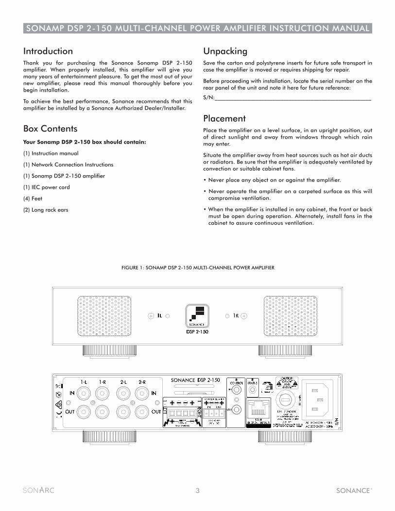
FIGURE 1: SONAMP DSP 2-150 MULTI-CHANNEL POWER AMPLIFIER
4
SONAMP DSP 2-150 MULTI-CHANNEL POWER AMPLIFIER INSTRUCTION MANUAL
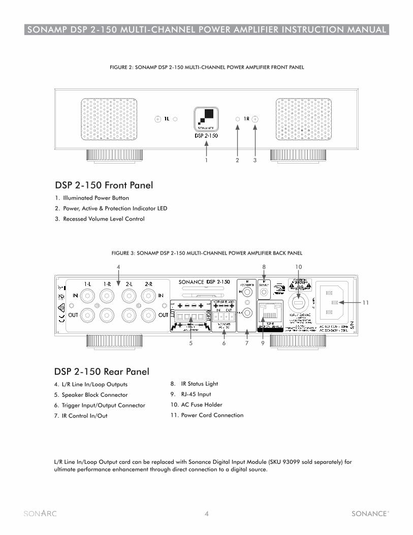
FIGURE 3: SONAMP DSP 2-150 MULTI-CHANNEL POWER AMPLIFIER BACK PANEL
FIGURE 2: SONAMP DSP 2-150 MULTI-CHANNEL POWER AMPLIFIER FRONT PANEL
DSP 2-150 Front Panel1. Illuminated Power Button
2. Power, Active & Protection Indicator LED
3. Recessed Volume Level Control
DSP 2-150 Rear Panel4. L/R Line In/Loop Outputs
5. Speaker Block Connector
6. Trigger Input/Output Connector
7. IR Control In/Out
8. IR Status Light
9. RJ-45 Input
10. AC Fuse Holder
11. Power Cord Connection
1 2 3
L/R Line In/Loop Output card can be replaced with Sonance Digital Input Module (SKU 93099 sold separately) for ultimate performance enhancement through direct connection to a digital source.
5 9
11
6 7
8 104
5
SONAMP DSP 2-150 MULTI-CHANNEL POWER AMPLIFIER INSTRUCTION MANUAL
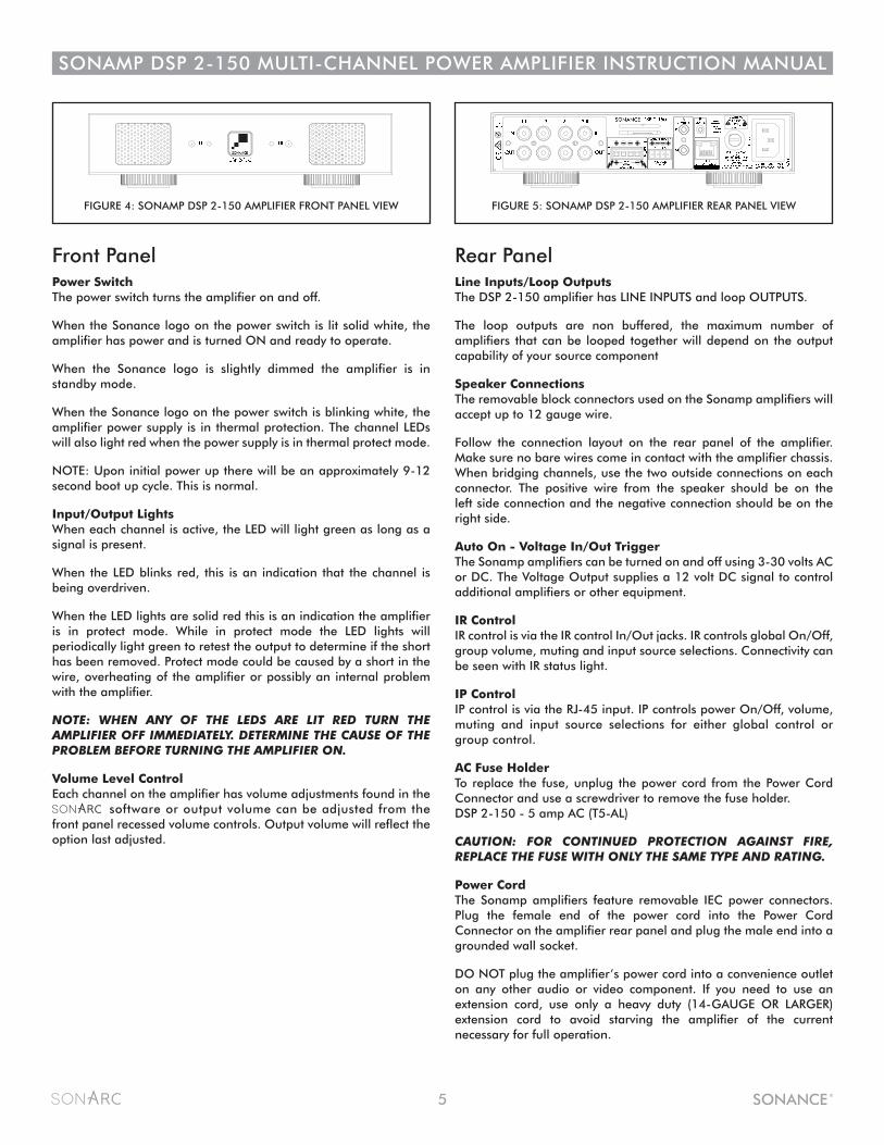
Front PanelPower Switch The power switch turns the amplifier on and off.
When the Sonance logo on the power switch is lit solid white, the amplifier has power and is turned ON and ready to operate.
When the Sonance logo is slightly dimmed the amplifier is in standby mode.
When the Sonance logo on the power switch is blinking white, the amplifier power supply is in thermal protection. The channel LEDs will also light red when the power supply is in thermal protect mode.
NOTE: Upon initial power up there will be an approximately 9-12 second boot up cycle. This is normal.
Input/Output LightsWhen each channel is active, the LED will light green as long as a signal is present.
When the LED blinks red, this is an indication that the channel is being overdriven.
When the LED lights are solid red this is an indication the amplifier is in protect mode. While in protect mode the LED lights will periodically light green to retest the output to determine if the short has been removed. Protect mode could be caused by a short in the wire, overheating of the amplifier or possibly an internal problem with the amplifier.
NOTE: WHEN ANY OF THE LEDS ARE LIT RED TURN THE AMPLIFIER OFF IMMEDIATELY. DETERMINE THE CAUSE OF THE PROBLEM BEFORE TURNING THE AMPLIFIER ON.
Volume Level ControlEach channel on the amplifier has volume adjustments found in the software or output volume can be adjusted from the front panel recessed volume controls. Output volume will reflect the option last adjusted.
Rear PanelLine Inputs/Loop OutputsThe DSP 2-150 amplifier has LINE INPUTS and loop OUTPUTS.
The loop outputs are non buffered, the maximum number of amplifiers that can be looped together will depend on the output capability of your source component
Speaker ConnectionsThe removable block connectors used on the Sonamp amplifiers will accept up to 12 gauge wire.
Follow the connection layout on the rear panel of the amplifier. Make sure no bare wires come in contact with the amplifier chassis.When bridging channels, use the two outside connections on each connector. The positive wire from the speaker should be on the left side connection and the negative connection should be on the right side.
Auto On - Voltage In/Out TriggerThe Sonamp amplifiers can be turned on and off using 3-30 volts AC or DC. The Voltage Output supplies a 12 volt DC signal to control additional amplifiers or other equipment.
IR ControlIR control is via the IR control In/Out jacks. IR controls global On/Off, group volume, muting and input source selections. Connectivity can be seen with IR status light.
IP ControlIP control is via the RJ-45 input. IP controls power On/Off, volume, muting and input source selections for either global control or group control.
AC Fuse HolderTo replace the fuse, unplug the power cord from the Power Cord Connector and use a screwdriver to remove the fuse holder.DSP 2-150 - 5 amp AC (T5-AL)
CAUTION: FOR CONTINUED PROTECTION AGAINST FIRE, REPLACE THE FUSE WITH ONLY THE SAME TYPE AND RATING.
Power CordThe Sonamp amplifiers feature removable IEC power connectors. Plug the female end of the power cord into the Power Cord Connector on the amplifier rear panel and plug the male end into a grounded wall socket.
DO NOT plug the amplifier’s power cord into a convenience outlet on any other audio or video component. If you need to use an extension cord, use only a heavy duty (14-GAUGE OR LARGER) extension cord to avoid starving the amplifier of the current necessary for full operation.
FIGURE 4: SONAMP DSP 2-150 AMPLIFIER FRONT PANEL VIEW FIGURE 5: SONAMP DSP 2-150 AMPLIFIER REAR PANEL VIEW
6
SONAMP DSP 2-150 MULTI-CHANNEL POWER AMPLIFIER INSTRUCTION MANUAL
Powering the AmplifierThe Sonamp DSP 2-150 features a removable IEC power connector (Figure 6). A 14-gauge EIA standard 120-volt grounded power cable is included with the amplifier.
Each time the amplifier’s power cord is initially plugged in and the POWER switch is turned ON, all channel outputs are disconnected for approximately 9-12 seconds and all PROTECTION LEDs will illuminate briefly while the amp boots up.
IMPORTANT: DO NOT PLUG THE POWER CORD INTO THE WALL OUTLET UNTIL ALL SYSTEM CONNECTIONS HAVE BEEN MADE AND VERIFIED.
Plug the female end of the power cable into the Power Connector on the amplifier’s rear panel and plug the male end directly into a grounded 15 amp or 20 amp wall outlet.
IMPORTANT: DO NOT PLUG THE AMPLIFIER’S POWER CORD INTO A CONVENIENCE OUTLET ON ANY OTHER AUDIO OR VIDEO COMPONENT.
If the electrical service is subject to frequent sags, spikes, or brownouts, a power conditioner designed for use with high fidelity equipment should be employed to protect the amplifier.
CAUTION: FOR CONTINUED PROTECTION AGAINST FIRE, REPLACE THE FUSE WITH ONLY THE SAME TYPE AND RATING.
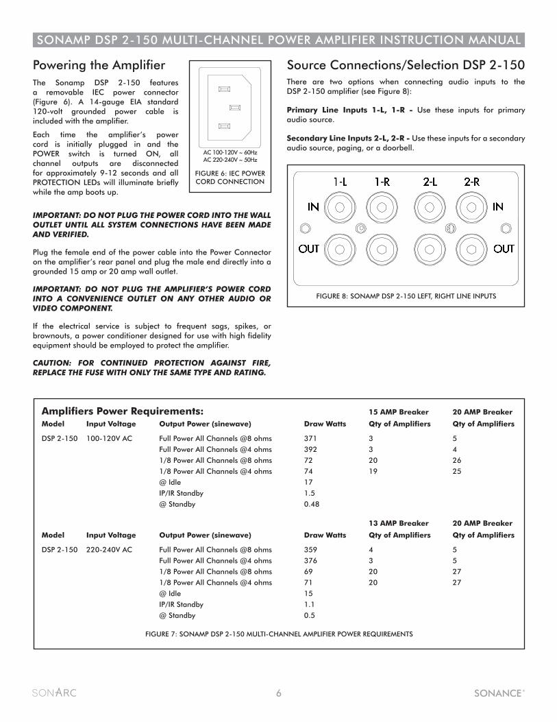
Source Connections/Selection DSP 2-150 There are two options when connecting audio inputs to the DSP 2-150 amplifier (see Figure 8):
Primary Line Inputs 1-L, 1-R - Use these inputs for primary audio source.
Secondary Line Inputs 2-L, 2-R - Use these inputs for a secondary audio source, paging, or a doorbell.
Amplifiers Power Requirements: 15 AMP Breaker 20 AMP Breaker
Model Input Voltage Output Power (sinewave) Draw Watts Qty of Amplifiers Qty of Amplifiers
DSP 2-150 100-120V AC Full Power All Channels @8 ohms 371 3 5
Full Power All Channels @4 ohms 392 3 4
1/8 Power All Channels @8 ohms 72 20 26
1/8 Power All Channels @4 ohms 74 19 25
@ Idle 17
IP/IR Standby 1.5
@ Standby 0.48
13 AMP Breaker 20 AMP Breaker
Model Input Voltage Output Power (sinewave) Draw Watts Qty of Amplifiers Qty of Amplifiers
DSP 2-150 220-240V AC Full Power All Channels @8 ohms 359 4 5
Full Power All Channels @4 ohms 376 3 5
1/8 Power All Channels @8 ohms 69 20 27
1/8 Power All Channels @4 ohms 71 20 27
@ Idle 15
IP/IR Standby 1.1
@ Standby 0.5
FIGURE 8: SONAMP DSP 2-150 LEFT, RIGHT LINE INPUTS
FIGURE 7: SONAMP DSP 2-150 MULTI-CHANNEL AMPLIFIER POWER REQUIREMENTS
IN
OUT
1-L 1-R LEVEL LEVELBRIDGEOFF ON
CAUTIONRISK OF ELECTRIC SHOCK
DO NOT OPEN
AVISRISQUE DE CHOC ELECTRIQUE
NE PAS OUVRIR
S/N
T5AL / 250VAC
2-100
AC 100-120V ~ 60Hz
CAUTION REPLACE FUSE ONLY WITHSAME TYPE AND RATING
ATTENTIONREMPLACER UNIQUEMENT AVEC LE MEME TYPE ET CALIBRE DU FUSIBLE
VOLTAGE TRIGGER
IN OUT AUTO ON
OFF
1-LEFT
1-R IG
HT
BRIDGE
CLASS 2 WIRING
VOLTA
GE
AU
DIO
3-30 VOLTSAC or DC8 Ω MIN
AC 220-240V ~ 50Hz
52 w
atts
FIGURE 6: IEC POWERCORD CONNECTION
7
SONAMP DSP 2-150 MULTI-CHANNEL POWER AMPLIFIER INSTRUCTION MANUAL
Speaker Connections
Bridging Channels DSP 2-150
FIGURE 13: VOLUME LEVEL CONTROL
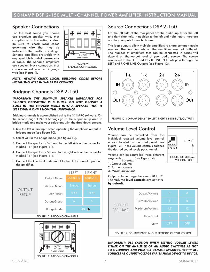
FIGURE 9:SPEAKER CONNECTORS
FIGURE 11: BRIDGING CHANNELS
Volume Level Control Volume can be controlled from the individual recessed volume level control screws, located on the front panel (see Figure 13). These volume controls balance the desired sound levels per channel.
Volume can be controlled three different ways with (see Figure 14).
1. Output volume 2. Turn on volume3. Maximum volume
Output volume ranges between -70 to 12. The volume level controls are set at 0 by default.
For the best sound you should use premium speaker wire, that complies with fire rating codes. Be sure to check local codes governing wire that may be installed within walls or ceilings. Sonamp amplifiers are stable with any reputable brand of speaker wire or cable. The Sonamp amplifiers use speaker block connectors that can accommodate up to 12 gauge wire (see Figure 9).
IMPORTANT: THE MINIMUM SPEAKER IMPEDANCE FOR BRIDGED OPERATION IS 8 OHMS. DO NOT OPERATE A ZONE IN THE BRIDGED MODE INTO A SPEAKER THAT IS LESS THAN 8 OHMS NOMINAL IMPEDANCE.
NOTE: ALWAYS CHECK LOCAL BUILDING CODES BEFORE INSTALLING WIRE IN WALLS OR CEILINGS.
IMPORTANT: USE CAUTION WHEN SETTING VOLUME LEVELS EITHER ON THE AMPLIFIER OR AN AUDIO SWITCHER AS NOT TO OVERDRIVE AND POSSIBLY DAMAGE SPEAKERS. VERIFY ALL SOURCES AS OUTPUT VOLTAGE VARIES FROM DEVICE TO DEVICE.
Source Connections DSP 2-150 On the left side of the rear panel are the audio inputs for the left and right channels. In addition to the left and right inputs there are also loop outputs for each channel.
The loop outputs allow multiple amplifiers to share common audio sources. The loop outputs on the amplifiers are not buffered. The number of amplifiers that can be connected in series will depend on the output level of your audio source. The source connected to the LEFT and RIGHT LINE IN Inputs pass through the LEFT and RIGHT LINE Outputs (see Figure 12).
Bridging channels is accomplished using the software. On the second page IN/OUT Settings go to the output setup area to bridge mode and make your selections with the drop down buttons.
1. Use the left audio input when operating the amplifiers output in bridged mode (see figure 10).
2. Select ON in the bridge mode (see figure 10).
3. Connect the speaker’s “+” lead to the left side of the connector marked “+” (see Figure 11).
4. Connect the speaker’s “–” lead to the right side of the connector marked “+” (see Figure 11).
5. Connect the line level audio input to the LEFT channel input on the amplifier.
LEVEL LEVELBRIDGEOFF ON
MONOSTEREO
12-50S/N
VOLTAGE TRIGGER
IN OUT AUTO ON
OFF
IN
OUT
IN
OUT
1-LEFT 1-RIGHT
LEVEL LEVELBRIDGEOFF ON
MONOSTEREO
LEVEL LEVELBRIDGEOFF ON
MONOSTEREO
LEVEL LEVELBRIDGEOFF ON
MONOSTEREO
LEVEL LEVELBRIDGEOFF ON
MONOSTEREO
LEVEL LEVELBRIDGEOFF ON
MONOSTEREO
2-LEFT 2-RIGHT 3-LEFT 3-RIGHT 4-LEFT 4-RIGHT 5-LEFT 5-RIGHT 6-LEFT 6-RIGHT
LOCALBUSS ABUSS B
LOCALBUSS ABUSS B
LOCALBUSS ABUSS B
LOCALBUSS ABUSS B
LOCALBUSS ABUSS B
LOCALBUSS ABUSS B
CAUTIONRISK OF ELECTRIC SHOCK
DO NOT OPEN
AVISRISQUE DE CHOC ELECTRIQUE
NE PAS OUVRIR
LEFT RIGHT LEFT RIGHT
BUSS INPUT A BUSS INPUT B
1-LEFT
1-RIG
HT
BRIDGE8 Ω MIN
CLASS 2 WIRING
T10AL / 250VACCAUTION
REPLACE FUSE ONLY WITHSAME TYPE AND RATING
ATTENTIONREMPLACER UNIQUEMENT AVEC LE MEME TYPE ET CALIBRE DU FUSIBLE2
-LEFT
2-RIG
HT
BRIDGE
CLASS 2 WIRING
3-LEFT
3-RIG
HT
BRIDGE
CLASS 2 WIRING
5-LEFT
5-RIG
HT
BRIDGE
CLASS 2 WIRING
6-LEFT
6-RIG
HT
BRIDGE
CLASS 2 WIRING
4-LEFT
4-RIG
HT
BRIDGE
CLASS 2 WIRING
VOLTA
GE
AU
DIO
3-30 VOLTSAC or DC8 Ω MIN 8 Ω MIN 8 Ω MIN 8 Ω MIN 8 Ω MIN
156 watts
AC 100-120V ~ 60HzAC 220-240V ~ 50Hz
LEVEL LEVELBRIDGEOFF ON
MONOSTEREO
12-50S/N
VOLTAGE TRIGGER
IN OUT AUTO ON
OFF
IN
OUT
IN
OUT
1-LEFT 1-RIGHT
LEVEL LEVELBRIDGEOFF ON
MONOSTEREO
LEVEL LEVELBRIDGEOFF ON
MONOSTEREO
LEVEL LEVELBRIDGEOFF ON
MONOSTEREO
LEVEL LEVELBRIDGEOFF ON
MONOSTEREO
LEVEL LEVELBRIDGEOFF ON
MONOSTEREO
2-LEFT 2-RIGHT 3-LEFT 3-RIGHT 4-LEFT 4-RIGHT 5-LEFT 5-RIGHT 6-LEFT 6-RIGHT
LOCALBUSS ABUSS B
LOCALBUSS ABUSS B
LOCALBUSS ABUSS B
LOCALBUSS ABUSS B
LOCALBUSS ABUSS B
LOCALBUSS ABUSS B
CAUTIONRISK OF ELECTRIC SHOCK
DO NOT OPEN
AVISRISQUE DE CHOC ELECTRIQUE
NE PAS OUVRIR
LEFT RIGHT LEFT RIGHT
BUSS INPUT A BUSS INPUT B
1-LEFT
1-RIG
HT
BRIDGE8 Ω MIN
CLASS 2 WIRING
T10AL / 250VACCAUTION
REPLACE FUSE ONLY WITHSAME TYPE AND RATING
ATTENTIONREMPLACER UNIQUEMENT AVEC LE MEME TYPE ET CALIBRE DU FUSIBLE2
-LEFT
2-RIG
HT
BRIDGE
CLASS 2 WIRING
3-LEFT
3-RIG
HT
BRIDGE
CLASS 2 WIRING
5-LEFT
5-RIG
HT
BRIDGE
CLASS 2 WIRING
6-LEFT
6-RIG
HT
BRIDGE
CLASS 2 WIRING
4-LEFT
4-RIG
HT
BRIDGE
CLASS 2 WIRING
VOLTA
GE
AU
DIO
3-30 VOLTSAC or DC8 Ω MIN 8 Ω MIN 8 Ω MIN 8 Ω MIN 8 Ω MIN
156 watts
AC 100-120V ~ 60HzAC 220-240V ~ 50Hz
FIGURE 10: BRIDGING CHANNELS
FIGURE 14: SONARC PAGE IN/OUT SETTINGS OUTPUT VOLUME
FIGURE 12: SONAMP DSP 2-150 LEFT, RIGHT LINE INPUTS/OUTPUTS
8
SONAMP DSP 2-150 MULTI-CHANNEL POWER AMPLIFIER INSTRUCTION MANUAL
Protection Circuitry and LEDsThe Sonamp amplifiers have a multi-stage protection system to prevent damage to your amplifier and speakers.
Amplifier Channel Protection DSP 2-150If a channel encounters a short-circuit (in bridged mode the protection circuitry will sense a short circuit across both positive speaker terminals), or extremely low impedance will cause the affected channel outputs to automatically mute. The output of the effected channel will remain muted until the fault has been corrected. Only the effected channels output will mute, all other channels will continue to operate normally.
Amplifier Channel Protection Indication DSP 2-150On the front panel of the Sonamp DSP 2-150 amplifiers are dual color LEDs that illuminate to indicate the current operating status of each amplifier channel.
When the LED blinks red this is an indication that the channel is being overdriven.
When the LED lights are solid red this is an indication the amplifier is in protect mode. While in protect mode the LED lights will periodically light green to retest the output to determine if the short has been removed. Protect mode could be caused by a short in the wire, overheating of the amplifier or possibly an internal problem with the amplifier.
IMPORTANT: ALLOWING THE AMPLIFIER TO OPERATE WITH ONE OR MORE CHANNELS IN PROTECT MODE FOR AN EXTENDED PERIOD OF TIME CAN DAMAGE THE AMPLIFIER.
Amplifier Power Supply Protection DSP 2-150The amplifier also has protection for the power supply. If the power supply heat sink temperature exceeds the design maximum, the protection circuit will activate, disconnecting all channel outputs. This is indicated by a blinking light on the front panel power switch.
IMPORTANT: ANY TIME THE PROTECTION CIRCUITS ARE TRIGGERED, UNPLUG THE AMPLIFIER’S POWER CORD FROM THE WALL OUTLET BEFORE TROUBLESHOOTING.
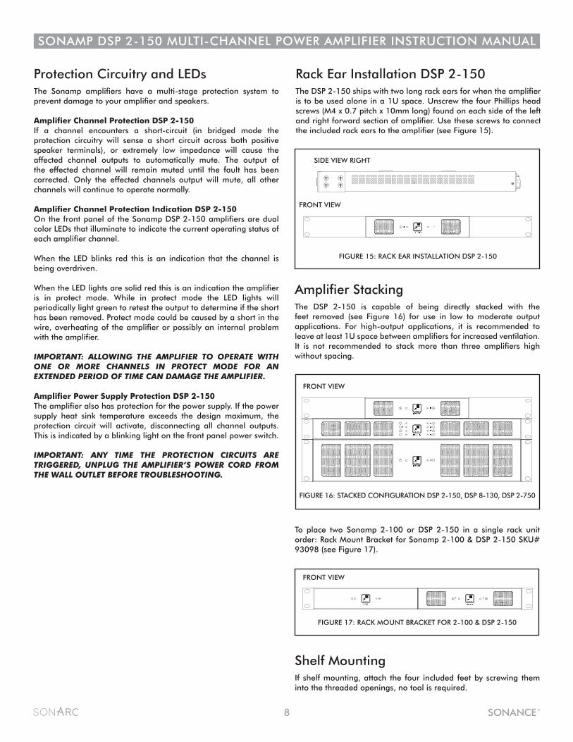
Rack Ear Installation DSP 2-150The DSP 2-150 ships with two long rack ears for when the amplifier is to be used alone in a 1U space. Unscrew the four Phillips head screws (M4 x 0.7 pitch x 10mm long) found on each side of the left and right forward section of amplifier. Use these screws to connect the included rack ears to the amplifier (see Figure 15).
FIGURE 15: RACK EAR INSTALLATION DSP 2-150
SIDE VIEW RIGHT
FRONT VIEW
Amplifier StackingThe DSP 2-150 is capable of being directly stacked with the feet removed (see Figure 16) for use in low to moderate output applications. For high-output applications, it is recommended to leave at least 1U space between amplifiers for increased ventilation. It is not recommended to stack more than three amplifiers high without spacing.
Shelf MountingIf shelf mounting, attach the four included feet by screwing them into the threaded openings, no tool is required.
To place two Sonamp 2-100 or DSP 2-150 in a single rack unit order: Rack Mount Bracket for Sonamp 2-100 & DSP 2-150 SKU# 93098 (see Figure 17).
1L 1R
2-100
FIGURE 16: STACKED CONFIGURATION DSP 2-150, DSP 8-130, DSP 2-750
FIGURE 17: RACK MOUNT BRACKET FOR 2-100 & DSP 2-150
FRONT VIEW
FRONT VIEW

9
SONAMP DSP 2-150 MULTI-CHANNEL POWER AMPLIFIER INSTRUCTION MANUAL
NETWORK CONNECTIONINSTRUCTIONS
Equipment List
Color Coded Interface
1. The amplifier factory settings has DHCP set to ON.
2. Connect the amplifier to a network with a router.
Make sure the computer and amplifier are on the same network.
3. Turn on the amplifier.
4. The amplifier will be issued an IP address by the router.
5. Use an IP Scanner to determine the IP Addresses of the Sonance DSP amps on the network.
We recommend Fing app for IOS and Advanced IP Scanner for Windows devices.
6. Network devices will show up and the amplifier will be named Sonance.
7. Open Safari, Chrome, or Internet Explorer.
8. In the URL address window at the top, enter the IP address of the Sonance DSP amplifier to configure.
1. Computer or tablet
2. Network router with DHCP service enabled
3. Two RJ-45 cables (one when using wireless)
Toggle/Pull-down Menu Free Type Field Single Action Menu
10
SONAMP DSP 2-150 MULTI-CHANNEL POWER AMPLIFIER INSTRUCTION MANUAL
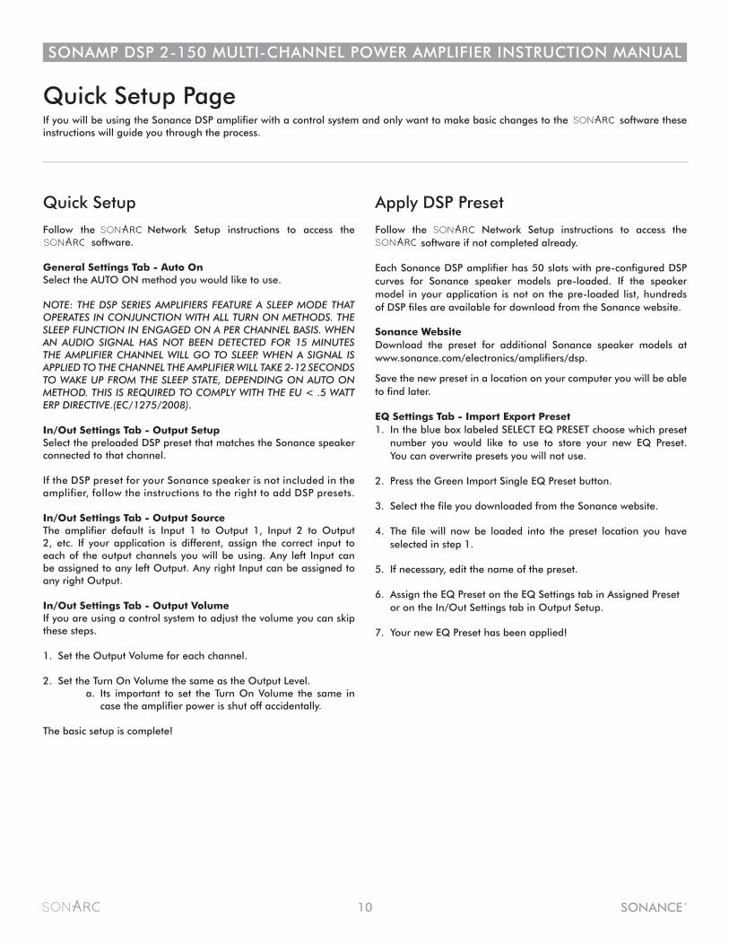
Quick Setup
Follow the Network Setup instructions to access the software.
General Settings Tab - Auto OnSelect the AUTO ON method you would like to use.
NOTE: THE DSP SERIES AMPLIFIERS FEATURE A SLEEP MODE THAT OPERATES IN CONJUNCTION WITH ALL TURN ON METHODS. THE SLEEP FUNCTION IN ENGAGED ON A PER CHANNEL BASIS. WHEN AN AUDIO SIGNAL HAS NOT BEEN DETECTED FOR 15 MINUTES THE AMPLIFIER CHANNEL WILL GO TO SLEEP. WHEN A SIGNAL IS APPLIED TO THE CHANNEL THE AMPLIFIER WILL TAKE 2-12 SECONDS TO WAKE UP FROM THE SLEEP STATE, DEPENDING ON AUTO ON METHOD. THIS IS REQUIRED TO COMPLY WITH THE EU < .5 WATT ERP DIRECTIVE.(EC/1275/2008).
In/Out Settings Tab - Output Setup Select the preloaded DSP preset that matches the Sonance speaker connected to that channel.
If the DSP preset for your Sonance speaker is not included in the amplifier, follow the instructions to the right to add DSP presets.
In/Out Settings Tab - Output Source The amplifier default is Input 1 to Output 1, Input 2 to Output 2, etc. If your application is different, assign the correct input to each of the output channels you will be using. Any left Input can be assigned to any left Output. Any right Input can be assigned to any right Output.
In/Out Settings Tab - Output Volume If you are using a control system to adjust the volume you can skip these steps.
1. Set the Output Volume for each channel.
2. Set the Turn On Volume the same as the Output Level. a. Its important to set the Turn On Volume the same in case the amplifier power is shut off accidentally.
The basic setup is complete!
Apply DSP Preset
Follow the Network Setup instructions to access the software if not completed already.
Each Sonance DSP amplifier has 50 slots with pre-configured DSP curves for Sonance speaker models pre-loaded. If the speaker model in your application is not on the pre-loaded list, hundreds of DSP files are available for download from the Sonance website.
Sonance WebsiteDownload the preset for additional Sonance speaker models at www.sonance.com/electronics/amplifiers/dsp.
Save the new preset in a location on your computer you will be able to find later.
EQ Settings Tab - Import Export Preset1. In the blue box labeled SELECT EQ PRESET choose which preset number you would like to use to store your new EQ Preset. You can overwrite presets you will not use.
2. Press the Green Import Single EQ Preset button.
3. Select the file you downloaded from the Sonance website.
4. The file will now be loaded into the preset location you have selected in step 1.
5. If necessary, edit the name of the preset.
6. Assign the EQ Preset on the EQ Settings tab in Assigned Preset or on the In/Out Settings tab in Output Setup.
7. Your new EQ Preset has been applied!
Quick Setup PageIf you will be using the Sonance DSP amplifier with a control system and only want to make basic changes to the software these instructions will guide you through the process.
11
SONAMP DSP 2-150 MULTI-CHANNEL POWER AMPLIFIER INSTRUCTION MANUAL
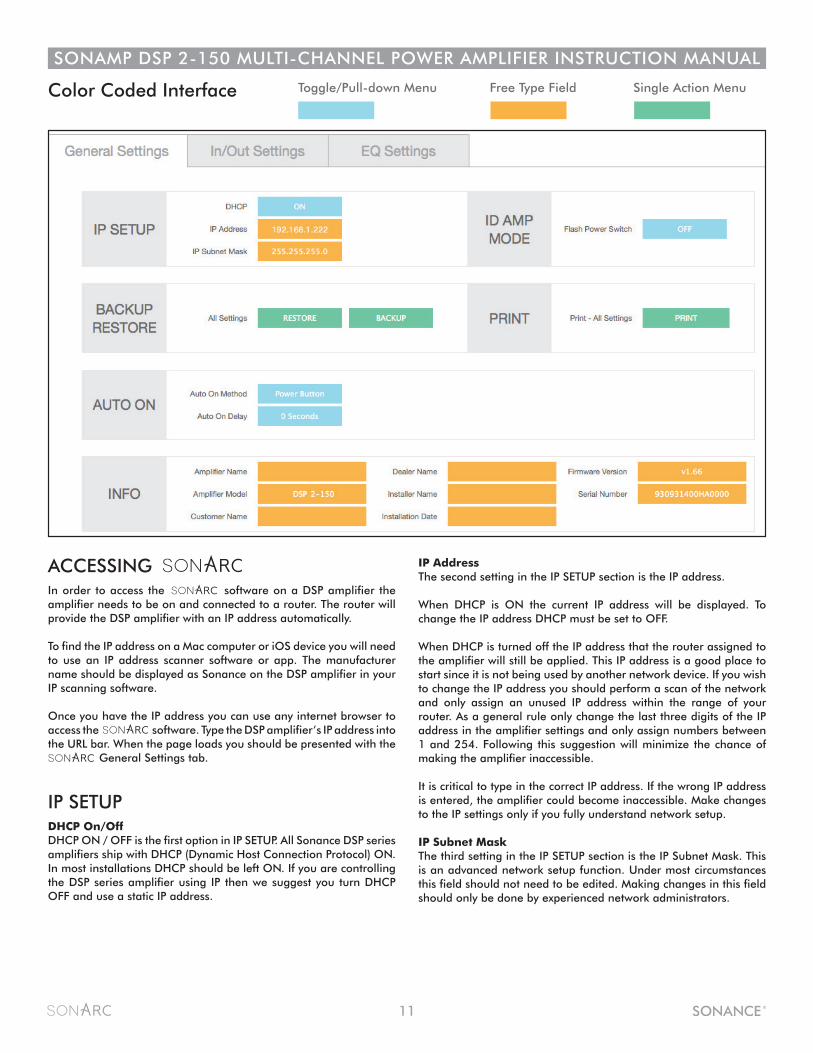
ACCESSING In order to access the software on a DSP amplifier the amplifier needs to be on and connected to a router. The router will provide the DSP amplifier with an IP address automatically.
To find the IP address on a Mac computer or iOS device you will need to use an IP address scanner software or app. The manufacturer name should be displayed as Sonance on the DSP amplifier in your IP scanning software.
Once you have the IP address you can use any internet browser to access the software. Type the DSP amplifier’s IP address into the URL bar. When the page loads you should be presented with the General Settings tab.
IP SETUP DHCP On/OffDHCP ON / OFF is the first option in IP SETUP. All Sonance DSP series amplifiers ship with DHCP (Dynamic Host Connection Protocol) ON. In most installations DHCP should be left ON. If you are controlling the DSP series amplifier using IP then we suggest you turn DHCP OFF and use a static IP address.
IP AddressThe second setting in the IP SETUP section is the IP address.
When DHCP is ON the current IP address will be displayed. To change the IP address DHCP must be set to OFF.
When DHCP is turned off the IP address that the router assigned to the amplifier will still be applied. This IP address is a good place to start since it is not being used by another network device. If you wish to change the IP address you should perform a scan of the network and only assign an unused IP address within the range of your router. As a general rule only change the last three digits of the IP address in the amplifier settings and only assign numbers between 1 and 254. Following this suggestion will minimize the chance of making the amplifier inaccessible.
It is critical to type in the correct IP address. If the wrong IP address is entered, the amplifier could become inaccessible. Make changes to the IP settings only if you fully understand network setup.
IP Subnet MaskThe third setting in the IP SETUP section is the IP Subnet Mask. This is an advanced network setup function. Under most circumstances this field should not need to be edited. Making changes in this field should only be done by experienced network administrators.
Color Coded Interface Toggle/Pull-down Menu Free Type Field Single Action Menu
12
SONAMP DSP 2-150 MULTI-CHANNEL POWER AMPLIFIER INSTRUCTION MANUAL
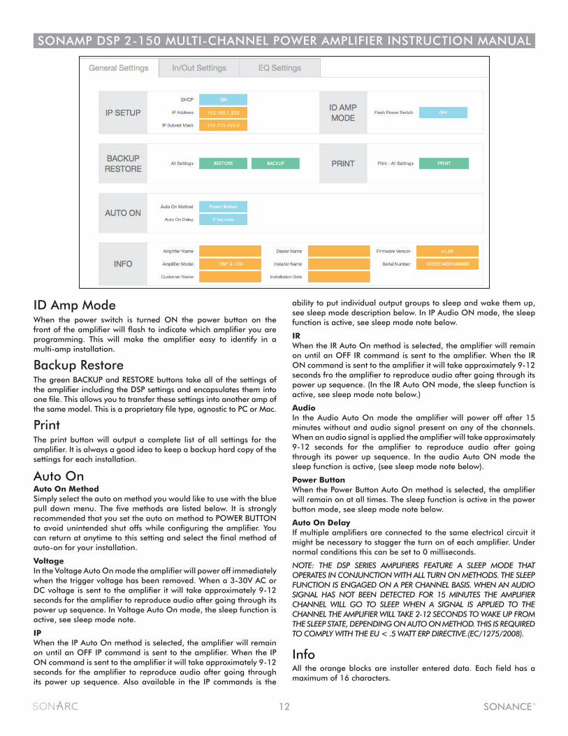
ability to put individual output groups to sleep and wake them up, see sleep mode description below. In IP Audio ON mode, the sleep function is active, see sleep mode note below.
IRWhen the IR Auto On method is selected, the amplifier will remain on until an OFF IR command is sent to the amplifier. When the IR ON command is sent to the amplifier it will take approximately 9-12 seconds fro the amplifier to reproduce audio after going through its power up sequence. (In the IR Auto ON mode, the sleep function is active, see sleep mode note below.)
AudioIn the Audio Auto On mode the amplifier will power off after 15 minutes without and audio signal present on any of the channels. When an audio signal is applied the amplifier will take approximately 9-12 seconds for the amplifier to reproduce audio after going through its power up sequence. In the audio Auto ON mode the sleep function is active, (see sleep mode note below).
Power ButtonWhen the Power Button Auto On method is selected, the amplifier will remain on at all times. The sleep function is active in the power button mode, see sleep mode note below.
Auto On DelayIf multiple amplifiers are connected to the same electrical circuit it might be necessary to stagger the turn on of each amplifier. Under normal conditions this can be set to 0 milliseconds.
NOTE: THE DSP SERIES AMPLIFIERS FEATURE A SLEEP MODE THAT OPERATES IN CONJUNCTION WITH ALL TURN ON METHODS. THE SLEEP FUNCTION IS ENGAGED ON A PER CHANNEL BASIS. WHEN AN AUDIO SIGNAL HAS NOT BEEN DETECTED FOR 15 MINUTES THE AMPLIFIER CHANNEL WILL GO TO SLEEP. WHEN A SIGNAL IS APPLIED TO THE CHANNEL THE AMPLIFIER WILL TAKE 2-12 SECONDS TO WAKE UP FROM THE SLEEP STATE, DEPENDING ON AUTO ON METHOD. THIS IS REQUIRED TO COMPLY WITH THE EU < .5 WATT ERP DIRECTIVE.(EC/1275/2008).
InfoAll the orange blocks are installer entered data. Each field has a maximum of 16 characters.
ID Amp ModeWhen the power switch is turned ON the power button on the front of the amplifier will flash to indicate which amplifier you are programming. This will make the amplifier easy to identify in a multi-amp installation.
Backup RestoreThe green BACKUP and RESTORE buttons take all of the settings of the amplifier including the DSP settings and encapsulates them into one file. This allows you to transfer these settings into another amp of the same model. This is a proprietary file type, agnostic to PC or Mac.
PrintThe print button will output a complete list of all settings for the amplifier. It is always a good idea to keep a backup hard copy of the settings for each installation.
Auto OnAuto On MethodSimply select the auto on method you would like to use with the blue pull down menu. The five methods are listed below. It is strongly recommended that you set the auto on method to POWER BUTTON to avoid unintended shut offs while configuring the amplifier. You can return at anytime to this setting and select the final method of auto-on for your installation.
VoltageIn the Voltage Auto On mode the amplifier will power off immediately when the trigger voltage has been removed. When a 3-30V AC or DC voltage is sent to the amplifier it will take approximately 9-12 seconds for the amplifier to reproduce audio after going through its power up sequence. In Voltage Auto On mode, the sleep function is active, see sleep mode note.
IPWhen the IP Auto On method is selected, the amplifier will remain on until an OFF IP command is sent to the amplifier. When the IP ON command is sent to the amplifier it will take approximately 9-12 seconds for the amplifier to reproduce audio after going through its power up sequence. Also available in the IP commands is the
13
SONAMP DSP 2-150 MULTI-CHANNEL POWER AMPLIFIER INSTRUCTION MANUAL
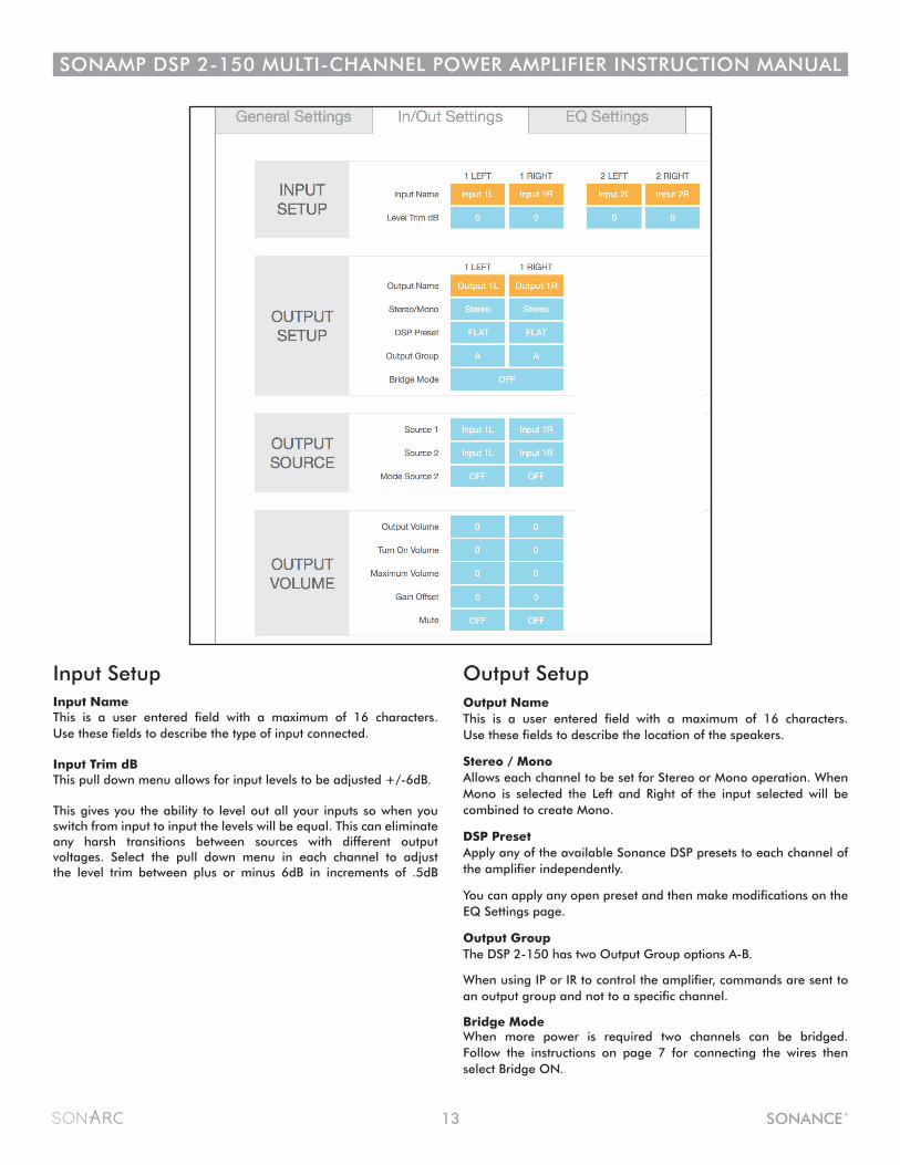
Input SetupInput NameThis is a user entered field with a maximum of 16 characters. Use these fields to describe the type of input connected.
Input Trim dBThis pull down menu allows for input levels to be adjusted +/-6dB.
This gives you the ability to level out all your inputs so when you switch from input to input the levels will be equal. This can eliminate any harsh transitions between sources with different output voltages. Select the pull down menu in each channel to adjust the level trim between plus or minus 6dB in increments of .5dB
Output SetupOutput NameThis is a user entered field with a maximum of 16 characters. Use these fields to describe the location of the speakers.
Stereo / MonoAllows each channel to be set for Stereo or Mono operation. When Mono is selected the Left and Right of the input selected will be combined to create Mono.
DSP PresetApply any of the available Sonance DSP presets to each channel of the amplifier independently.
You can apply any open preset and then make modifications on the EQ Settings page.
Output GroupThe DSP 2-150 has two Output Group options A-B.
When using IP or IR to control the amplifier, commands are sent to an output group and not to a specific channel.
Bridge ModeWhen more power is required two channels can be bridged. Follow the instructions on page 7 for connecting the wires then select Bridge ON.

14
SONAMP DSP 2-150 MULTI-CHANNEL POWER AMPLIFIER INSTRUCTION MANUAL
Output SourceSource 1This is the primary source you will direct to the speakers. Any of the inputs available on the amplifier can be selected. When channels are in the same Output Group the inputs will all change in unison. Left inputs default to left outputs and right inputs to right outputs.
Source 2This is a secondary source that based on the Mode Source 2 setting described below will either override or mix with Source 1. This input could be used for a doorbell or paging for example.
Mode Source 2
OFFWhen set to OFF the second source has no effect on the operation of the channel.
MIXWhen set to MIX Source 1 and Source 2 will be blended together when a signal is present on Source 2.
MUTEWhen set to MUTE Source 1 will be muted while Source 2 is active.
Output VolumeOutput volume ranges between -70 to 12. The default volume level controls are set at 0.
Output VolumeThis is the main volume level control for each channel. When channels are placed in the same Output Group the levels will change simultaneously.
Turn On VolumeThis determines what volume level the amplifier will default to when it is turned on. Channels placed in the same Output Group will automatically have identical levels. Turn On Volume level is implemented when the amplifier is turned off with the power switch or goes into standby mode.
Maximum VolumeThis is an independent setting for each channel. This can be used to limit how loud the speakers will play in certain areas. The Output Group selected does not affect this setting.
Gain OffsetThe gain offset setting allows channels in the same Output Group to have their levels adjusted independently by +/-6dB. This is an independent setting not affected by the Output Group.
MuteThe mute setting eliminates the output from the speakers. Channels placed in the same Output Group will change simultaneously.
15
SONAMP DSP 2-150 MULTI-CHANNEL POWER AMPLIFIER INSTRUCTION MANUAL
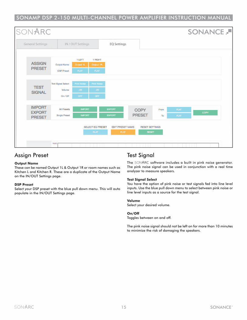
Assign PresetOutput NameThese can be named Output 1L & Output 1R or room names such as Kitchen L and Kitchen R. These are a duplicate of the Output Name on the IN/OUT Settings page.
DSP PresetSelect your DSP preset with the blue pull down menu. This will auto populate in the IN/OUT Settings page.
Test Signal The software includes a built in pink noise generator. The pink noise signal can be used in conjunction with a real time analyzer to measure speakers.
Test Signal SelectYou have the option of pink noise or test signals fed into line level inputs. Use the blue pull down menu to select between pink noise or line level inputs as a source for the test signal.
VolumeSelect your desired volume.
On/OffToggles between on and off.
The pink noise signal should not be left on for more than 10 minutes to minimize the risk of damaging the speakers.

16
SONAMP DSP 2-150 MULTI-CHANNEL POWER AMPLIFIER INSTRUCTION MANUAL
Import Export PresetAll PresetsThe green IMPORT EXPORT buttons allow you to save all 50 presets in one file. This option can be useful when setting up multiple amplifiers.
Single PresetThe green IMPORT EXPORT buttons allow you to import or export presets individually.
Export Single Preset 1. Use the blue pull down menu on the SELECT EQ PRESET, located under the IMPORT EXPORT green buttons. 2. Select the preset you choose to export from the pull down menu. 3. Press the green EXPORT button. Depending on your web browser the exported file will be saved in your Downloads folder or you will be prompted where you would like to save the file.
Import Single Preset 1. Import speaker preset to a location on your computer. This can be accomplished by saving a DSP preset downloaded from Sonance website. 2. Select the location you would like to store the new preset using the SELECT EQ PRESET pull down menu. You can save the new preset in any of the open preset locations or you can overwrite an existing preset you do not need.3. Press the green IMPORT button. 4. You will be directed to my computer or FINDER.5. Find and Select the new preset you would like to import6. You will be directed to a screen that says Upload Successful.7. Press the Click Here To Go Back to the highlighted text8. The preset will now be saved in the location you selected.
Copy PresetFrom / To the blue pull down menus allow you to pull a preset from one location and assign it to another location. Press green copy button to activate.
Select EQ PresetThis is a pull down menu that allows the selection of any one of the 50 available presets.
When you want to edit a particular preset you simply select it in the Select EQ Preset pull down menu. Any changes you make are saved immediately.
Edit Preset NameThis field allows the name of the preset to be edited. There is a maximum of 16 characters that can be entered.
Reset SettingsThis is a simple reset button to cancel edits and return to the original preset if you are unable to achieve the target frequency response.
17
SONAMP DSP 2-150 MULTI-CHANNEL POWER AMPLIFIER INSTRUCTION MANUAL
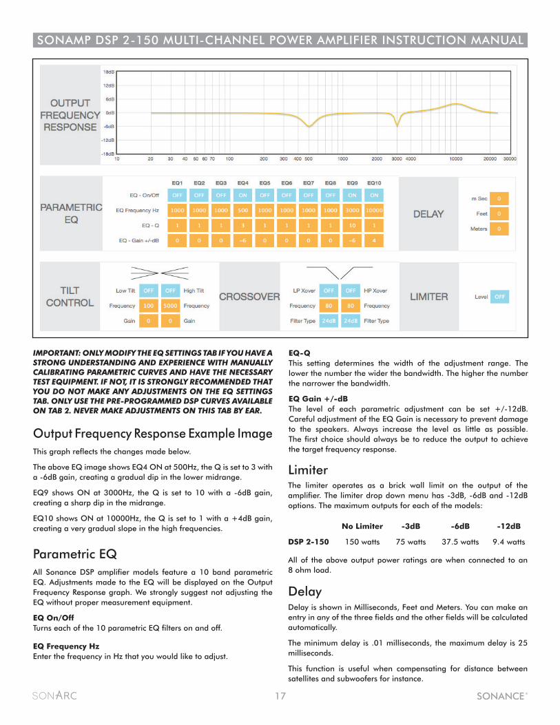
Parametric EQAll Sonance DSP amplifier models feature a 10 band parametric EQ. Adjustments made to the EQ will be displayed on the Output Frequency Response graph. We strongly suggest not adjusting the EQ without proper measurement equipment.
EQ On/Off Turns each of the 10 parametric EQ filters on and off.
EQ Frequency Hz Enter the frequency in Hz that you would like to adjust.
EQ-QThis setting determines the width of the adjustment range. The lower the number the wider the bandwidth. The higher the number the narrower the bandwidth.
EQ Gain +/-dBThe level of each parametric adjustment can be set +/-12dB. Careful adjustment of the EQ Gain is necessary to prevent damage to the speakers. Always increase the level as little as possible. The first choice should always be to reduce the output to achieve the target frequency response.
Output Frequency Response Example ImageThis graph reflects the changes made below.
The above EQ image shows EQ4 ON at 500Hz, the Q is set to 3 with a -6dB gain, creating a gradual dip in the lower midrange.
EQ9 shows ON at 3000Hz, the Q is set to 10 with a -6dB gain, creating a sharp dip in the midrange.
EQ10 shows ON at 10000Hz, the Q is set to 1 with a +4dB gain, creating a very gradual slope in the high frequencies.
Limiter The limiter operates as a brick wall limit on the output of the amplifier. The limiter drop down menu has -3dB, -6dB and -12dB options. The maximum outputs for each of the models:
All of the above output power ratings are when connected to an 8 ohm load.
DelayDelay is shown in Milliseconds, Feet and Meters. You can make an entry in any of the three fields and the other fields will be calculated automatically.
The minimum delay is .01 milliseconds, the maximum delay is 25 milliseconds.
This function is useful when compensating for distance between satellites and subwoofers for instance.
No Limiter -3dB -6dB -12dB
DSP 2-150 150 watts 75 watts 37.5 watts 9.4 watts
IMPORTANT: ONLY MODIFY THE EQ SETTINGS TAB IF YOU HAVE A STRONG UNDERSTANDING AND EXPERIENCE WITH MANUALLY CALIBRATING PARAMETRIC CURVES AND HAVE THE NECESSARY TEST EQUIPMENT. IF NOT, IT IS STRONGLY RECOMMENDED THAT YOU DO NOT MAKE ANY ADJUSTMENTS ON THE EQ SETTINGS TAB. ONLY USE THE PRE-PROGRAMMED DSP CURVES AVAILABLE ON TAB 2. NEVER MAKE ADJUSTMENTS ON THIS TAB BY EAR.
18
SONAMP DSP 2-150 MULTI-CHANNEL POWER AMPLIFIER INSTRUCTION MANUAL
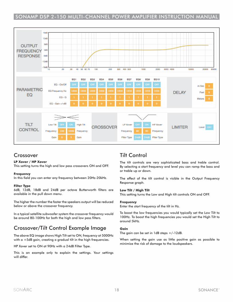
CrossoverLP Xover / HP XoverThis setting turns the high and low pass crossovers ON and OFF. FrequencyIn this field you can enter any frequency between 20Hz-20kHz. Filter Type6dB, 12dB, 18dB and 24dB per octave Butterworth filters are available in the pull down menu.
The higher the number the faster the speakers output will be reduced below or above the crossover frequency.
In a typical satellite subwoofer system the crossover frequency would be around 80-100Hz for both the high and low pass filters.
Crossover/Tilt Control Example ImageThe above EQ image shows High Tilt set to ON, frequency at 5000Hz with a +5dB gain, creating a gradual tilt in the high frequencies.
HP Xover set to ON at 90Hz with a 24dB Filter Type.
This is an example only to explain the settings. Your settings will differ.
Tilt ControlThe tilt controls are very sophisticated bass and treble control. By selecting a start frequency and level you can ramp the bass and or treble up or down.
The effect of the tilt control is visible in the Output Frequency Response graph.
Low Tilt / High Tilt This setting turns the Low and High tilt controls ON and OFF.
Frequency Enter the start frequency of the tilt in Hz.
To boost the low frequencies you would typically set the Low Tilt to 100Hz. To boost the high frequencies you would set the High Tilt to around 5kHz.
Gain The gain can be set in 1dB steps +/-12dB.
When setting the gain use as little positive gain as possible to minimize the risk of damage to the loudspeakers.
19
SONAMP DSP 2-150 MULTI-CHANNEL POWER AMPLIFIER INSTRUCTION MANUAL
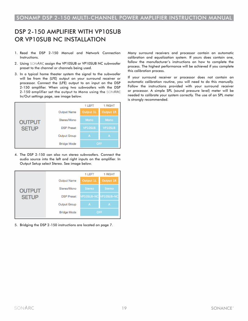
DSP 2-150 AMPLIFIER WITH VP10SUB OR VP10SUB NC INSTALLATION
1. Read the DSP 2-150 Manual and Network Connection Instructions.
2. Using assign the VP10SUB or VP10SUB NC subwoofer preset to the channel or channels being used.
3. In a typical home theater system the signal to the subwoofer will be from the (LFE) output on your surround receiver or processor. Connect the (LFE) output to an input on the DSP 2-150 amplifier. When using two subwoofers with the DSP 2-150 amplifier set the output to Mono using the In/Out settings page, see image below.
Many surround receivers and processor contain an automatic calibration and equalization system. If yours does contain one, follow the manufacturer’s instructions on how to complete the process. The highest performance will be achieved if you complete this calibration process.
If your surround receiver or processor does not contain an automatic calibration routine, you will need to do this manually. Follow the instructions provided with your surround receiver or processor. A simple SPL (sound pressure level) meter will be needed to calibrate your system correctly. The use of an SPL meter is strongly recommended.
4. The DSP 2-150 can also run stereo subwoofers. Connect the audio source into the left and right inputs on the amplifier. In Output Setup select Stereo. See image below.
5. Bridging the DSP 2-150 instructions are located on page 7.
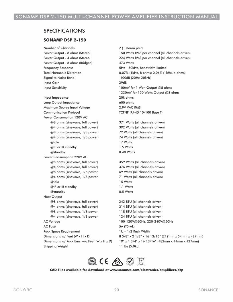
SPECIFICATIONS
SONAMP DSP 2-150
Number of Channels 2 (1 stereo pair)
Power Output - 8 ohms (Stereo) 150 Watts RMS per channel (all channels driven)
Power Output - 4 ohms (Stereo) 224 Watts RMS per channel (all channels driven)
Power Output - 8 ohms (Bridged) 473 Watts
Frequency Response 5Hz – 50kHz, bandwidth limited
Total Harmonic Distortion 0.07% (1kHz, 8 ohms) 0.06% (1kHz, 4 ohms)
Signal to Noise Ratio -100dB (20Hz-20kHz)
Input Gain 29dB
Input Sensitivity 100mV for 1 Watt Output @8 ohms
1230mV for 150 Watts Output @8 ohms
Input Impedance 20k ohms
Loop Output Impedance 600 ohms
Maximum Source Input Voltage 2.9V VAC RMS
Communication Protocol TCP/IP (RJ-45 10/100 Base T)
Power Consumption 120V AC
@8 ohms (sinewave, full power) 371 Watts (all channels driven)
@4 ohms (sinewave, full power) 392 Watts (all channels driven)
@8 ohms (sinewave, 1/8 power) 72 Watts (all channels driven)
@4 ohms (sinewave, 1/8 power) 74 Watts (all channels driven)
@idle 17 Watts
@IP or IR standby 1.5 Watts
@standby 0.48 Watts
Power Consumption 220V AC
@8 ohms (sinewave, full power) 359 Watts (all channels driven)
@4 ohms (sinewave, full power) 376 Watts (all channels driven)
@8 ohms (sinewave, 1/8 power) 69 Watts (all channels driven)
@4 ohms (sinewave, 1/8 power) 71 Watts (all channels driven)
@idle 15 Watts
@IP or IR standby 1.1 Watts
@standby 0.5 Watts
Heat Output
@8 ohms (sinewave, full power) 242 BTU (all channels driven)
@4 ohms (sinewave, full power) 314 BTU (all channels driven)
@8 ohms (sinewave, 1/8 power) 118 BTU (all channels driven)
@4 ohms (sinewave, 1/8 power) 124 BTU (all channels driven)
AC Voltage 100-120V@60Hz, 220-240V@50Hz
AC Fuse 5A (T5-AL)
Rack Space Requirement 1U – 1/2 Rack Width
Dimensions w/ Feet (W x H x D) 8 5/8” x 2 1/8” x 16 13/16” (219mm x 54mm x 427mm)
Dimensions w/ Rack Ears w/o Feet (W x H x D) 19” x 1 3/4” x 16 13/16” (482mm x 44mm x 427mm)
Shipping Weight 11 lbs (5.0kg)
CAD Files available for download at www.sonance.com/electronics/amplifiers/dsp
20
SONAMP DSP 2-150 MULTI-CHANNEL POWER AMPLIFIER INSTRUCTION MANUAL
©2016 Sonance. All rights reserved.Sonance and Sonamp are registered trademarks of Dana Innovations.
Due to continuous product improvement, all features and specifications are subject to change without notice. For the latest Sonance product specification information visit our website: www.sonance.com
SONANCE • 212 Avenida Fabricante • San Clemente, CA 92672-7531 USA(949) 492-7777 • FAX: (949) 361-5151 • Technical Support: (949) 492-7777
www.sonance.com
33-7404 02.04.16
LIMITED TWO (2) YEAR WARRANTY Sonance warrants to the first end-user purchaser that this Sonance-brand product (“Product”), when purchased from an authorized Sonance Dealer/Distributor, will be free from defective workmanship and materials for the period stated below. Sonance will at its option and expense during the warranty period, either repair the defect or replace the Product with a new or remanufactured Product or a reasonable equivalent.
EXCLUSIONSTO THE EXTENT PERMITTED BY LAW, THE WARRANTY SET FORTH ABOVE IS IN LIEU OF, AND EXCLUSIVE OF, ALL OTHER WARRANTIES, EXPRESS OR IMPLIED, AND IS THE SOLE AND EXCLUSIVE WARRANTY PROVIDED BY SONANCE. ALL OTHER EXPRESS AND IMPLIED WARRANTIES, INCLUDING THE IMPLIED WARRANTIES OF MERCHANTABILITY, IMPLIED WARRANTY OF FITNESS FOR USE, AND IMPLIED WARRANTY OF FITNESS FOR A PARTICULAR PURPOSE ARE SPECIFICALLY EXCLUDED.
No one is authorized to make or modify any warranties on behalf of Sonance. The warranty stated above is the sole and exclusive remedy and Sonance’s performance shall constitute full and final satisfaction of all obligations, liabilities and claims with respect to the Product.
IN ANY EVENT, SONANCE SHALL NOT BE LIABLE FOR CONSEQUENTIAL, INCIDENTAL, ECONOMIC, PROPERTY, BODILY INJURY, OR PERSONAL INJURY DAMAGES ARISING FROM THE PRODUCT, ANY BREACH OF THIS WARRANTY OR OTHERWISE.
This warranty statement gives you specific legal rights, and you may have other rights which vary from state to state. Some states do not allow the exclusion of implied warranties or limitations of remedies, so the above exclusions and limitations may not apply. If your state does not allow disclaimer of implied warranties, the duration of such implied warranties is limited to period of Sonance’s express warranty.
Your Product Model and Description: Sonamp DSP 2-150 Multi-Channel Power Amplifier
Warranty Period for this Product: Two (2) years from the date on the original sales receipt or invoice or other satisfactory proof of purchase.
Additional Limitations and Exclusions from Warranty Coverage: The warranty described above is non-transferable, applies only to the initial installation of the Product, does not include installation of any repaired or replaced Product, does not include damage to allied or associated equipment which may result for any reason from use with this Product, and does not include labor or parts caused by accident, disaster, negligence, improper installation, misuse (e.g. overdriving the amplifier or speaker, excessive heat, cold or humidity), or from service or repair which has not been authorized by Sonance. Obtaining Authorized Service: To qualify for the warranty, you must contact your authorized Sonance Dealer/Installer or call Sonance Customer Service at (949) 492-7777 within the warranty period, must obtain a return merchandise number (RMA), and must deliver the Product to Sonance shipping prepaid during the warranty period, together with the original sales receipt, or invoice or other satisfactory proof of purchase.
SONAMP DSP 2-150 MULTI-CHANNEL POWER AMPLIFIER INSTRUCTION MANUAL
21