Instruction Manual for DODGE USN 600 Series Adaptor ... · Instruction Manual for DODGE® USN 600...
12
Instruction Manual for DODGE ® USN 600 Series Adaptor Mounted & 300 Series Direct Mounted Plummer Blocks WARNING: Because of the possible danger to person(s) or property from accidents which may result from the improper use of products, it is important that correct procedures be followed. Products must be used in accordance with the engineering information specified in the catalog. Proper installation, maintenance and operation procedures must be observed. The instructions in the instruction manuals must be followed. Inspections should be made as necessary to assure safe operation under prevailing conditions. Proper guards and other suitable safety devices or procedures as may be desirable or as may be specified in safety codes should be provided, and are neither provided by Baldor Electric Company nor are the responsibility of Baldor Electric Company. This unit and its associated equipment must be installed, adjusted and maintained by qualified personnel who are familiar with the construction and operation of all equipment in the system and the potential hazards involved. When risk to persons or property may be involved, a holding device must be an integral part of the driven equipment beyond the speed reducer output shaft.
-
Upload
trinhkhanh -
Category
Documents
-
view
236 -
download
0
Transcript of Instruction Manual for DODGE USN 600 Series Adaptor ... · Instruction Manual for DODGE® USN 600...

Instruction Manual for
DODGE® USN 600 Series Adaptor Mounted & 300 Series
Direct Mounted Plummer Blocks
WARNING: Because of the possible danger to person(s) or property from accidents which may result from the improper use of products, it is important that correct procedures be followed. Products must be used in accordance with the engineering information specified in the catalog. Proper installation, maintenance and operation procedures must be observed. The instructions in the instruction manuals must be followed. Inspections should be made as necessary to assure safe operation under prevailing conditions. Proper guards and other suitable safety devices or procedures as may be desirable or as may be specified in safety codes should be provided, and are neither provided by Baldor Electric Company nor are the responsibility of Baldor Electric Company. This unit and its associated equipment must be installed, adjusted and maintained by qualified personnel who are familiar with the construction and operation of all equipment in the system and the potential hazards involved. When risk to persons or property may be involved, a holding device must be an integral part of the driven equipment beyond the speed reducer output shaft.


2
INSPECTION
GENERAL INFORMATION
WARNINGTo ensure that drive is not unexpectedly started, turn off and lock out or tag power source before proceeding. Failure to observe these precautions could result in bodily injury. Read all instructions thoroughly before beginning.
DODGE USN™ bearings conform with all appropriate ISO standards. They are available in either adaptor or direct mounting styles. A wide variety of seals is available including Standard metallic LER, TRIPLE-TECT™ non-metallic seal with V-ring, Drop-in TRIPLE-TECT seal with neoprene V-ring, Auxiliary Taconite or Split non-metallic. TRIPLE-TECT seal is provided as standard on complete assemblies. DODGE USN housings provide you with maximum application flexibility. Cast in dimples allow for easy field modification for vents, lube ports and sensors. Oversized drains and an oil equalization hole make USN bearings ready for circulating oil systems off the shelf. For hostile environments, USN offers optional.
cast closed end housings, stainless hardware kits, and nylon coating. Complete installation, maintenance and modification instructions are provided in this manual. Inspect shaft — Ensure that the shaft is smooth, straight, clean, and within commercial tolerances. Inspect bearing — Do not allow bearing to be exposed to any dirt or moisture. Do not remove slushing compound as it acts as both a protectant and lubricant and is also compatible with standard greases. Note: Housing caps and bases are not interchangeable. They must be matched with mating half. Install non-expansion bearing first. Note: For seal types other than TRIPLE TECT such as drop-in TRIPLE TECT, LER, auxiliary seals and split seals follow seal instruction manual 499665 supplied with the seals.Note: For an explanation of the various dimples and tapped holes found on the USN housings, see Table 11, page 7.
INSTALLATION (USN 600 SERIES) ADAPTOR MOUNTED 1. Apply a coating of light oil or other rust inhibitor to the adaptor area of the shaft. 2. Measure the internal clearance of the bearing before mounting. Place the bearing in an upright position as shown in Figure 1. Seat the inner ring and roller elements by pressing down firmly on the inner ring bore while rotating the inner ring a few times. Position the roller assemblies so that a roller is at the top most position on both sides. Using a feeler gauge measure the clearance for both sides by inserting as far as possible and sliding over top of roller (Figure 1). Write down the measured clearance for use in step 3e. Note: Do not rotate bearing when moving feeler between roller and outer ring.
3. Install the bearing parts in the following sequence: (refer to parts drawing):
a) V-ring Seal — Slide one of the V-ring seals onto the shaft, making sure lip is toward the bearing. Note: Donot install V-ring seal on seal ring until housing cap has been set in place and tightened. b) Seal Ring — Install a seal ring on shaft with largest O.D. toward bearing.

3
c) Adaptor Sleeve — Slide adaptor sleeve onto the shaft, threaded end outboard to the approximate location of the bearing. Apply light coating of oil to sleeve O.D. Do Not Use Grease. d) Bearing — Make sure that the internal clearance has been written down. Install bearing on adaptor sleeve, large end of tapered bore first. Locate bearing in proper position on shaft.
e) Lockwasher and Locknut — Install the lock-washer on the adaptor sleeve with inner prong located in the slot of the sleeve and pointing towards the bearing. Install locknut, chamfered face toward bearing as follows:
For 100 mm diameter shafts and smaller — Tighten locknut using a spanner wrench and hammer until clearance noted in Step 2 is reduced by amount shown in Table 1. During this step shaft should be supported so all weight is off of the bearing.
Table 1 — Adaptor Mounted Bearings Only
Shaft Diameter, MM Reduction in*
Internal Clearance (MM) 35, 40 .020–.025 45, 50 .025–.030 55, 60, 65 .030–.038 70, 75 .038–.051 85, 90, 100 .046–.064 110, 115 .051–.066
* Amount of clearance to be removed from clearance measured in Step 2.
For larger than 100 mm diameter shafts — Tighten locknut by hand followed by light tapping on a bar inserted in notches on O.D. of locknut. Tighten all MICRO-MOUNT® screws evenly in sequence and in small increments 10° to 15° turns until clearance is reduced.
Loosen all screws until they are snug at large end of nut. Screws have been staked at factory to prevent removal, however, restake if necessary. Tighten locknut until it is tight against bearing (use drift pin and hammer).
Now find a lockwasher tab that aligns with a locknut slot and bend tab into slot. If slot is past tab then tighten, not loosen, locknut to meet a washer tab.
Steps f) and g) are not necessary if pillow block housing is a cast closed end style.
f) Seal Ring — Install second seal ring with large O.D. toward locknut.
g) V-ring Seal — Slide second V-ring seal onto the shaft, again making certain lip is toward bearing. Do not install V-ring seal on seal ring until housing cap has been set in place and tightened. For assistance in installing seals, use seal instruction manual 499665 supplied with the seals.
4. Remove any paint, dirt or burrs from the mating surfaces of the housing halves. Thoroughly clean seal grooves on both sides. Set lower half of housing on base and apply oil to the bearing seats.
5. Apply grease to the bearing and seal rings. The lubricant should be smeared between the rolling elements (see Grease Lubrication section). This step and the first sentence of step 9 do not apply for oil-lubricated bearings. 6. Place shaft with bearing into lower half while carefully guiding the seal rings into the housing grooves.
7. Bolt lower half of the non-expansion bearing to the base. Move shaft endwise so that spacer ring can be inserted as shown on Sketch 1. Center all other bearings on same shaft in their housing seats. Note: Only one bearing per shaft is
non-expansion, other bearings should be expansion. When plummer block is subjected to heavy cap loads use property torqued metric grade 10,9 base bolts to mount to structure. 8. When closed end is required and the block is not a cast closed, an optional end plug may be fit into the center seal ring groove of the housing. Shaft extension should not be beyond adaptor end to ensure no rubbing with end plug or housing on cast closed end.
9. Grease the bearing seal grooves in the housing cap and place over the bearing after wiping the mating surfaces (does not apply for oil-lubricated bearings). The two dowel pins will align the cap with the lower housing half. Note: Each cap must be matched with its mating lower half, as these parts are not interchangeable. Cap and base have serial number stamped at joint. The serial numbers should line up for proper match. If the blocks are mounted other than in the horizontal position, a sealer must be applied at the cap and base mating surfaces.
10. Tighten cap bolts to the recommended torque shown on Table 2.
11. Assure that there is running clearance at seal rings, then install V-ring onto the seal rings as shown on Sketch 2. Coat V-ring seal with grease to protect against ozone attack.
12. Misalignment of plummer blocks must not exceed ± ½° (one-half degree).
Table 2 — Recommended Torque Values Nm Bolt Size, mm 10 12 16 20 24
Grade 8.8 47–51 81–89 203–215 415–420 720–725Stainless Steel A2/A4 Class 70 24 40 110 170 –
INSTALLATION (USN 300 SERIES) DIRECT MOUNTED
WARNING To ensure that drive is not unexpectedly started, turn off and lock out or tag power source before proceeding. Failure to observe these precautions could result in bodily injury. Read instructions thoroughly before beginning.
1. Measure the internal clearance of the bearing before mounting. Place the bearing in an upright position as shown in Figure 1. Seat the inner ring and roller elements by pressing down firmly on the inner ring bore while rotating the inner ring a few times. Position the roller assemblies so that a roller is at the top most position on both sides, using a feeler gauge measure the clearance for both sides by

4
inserting as far as possible and sliding over top of roller (Figure 1). Write down the measured clearance and compare with specifications Table 3. Note: Do not rotate bearing when moving feeler between roller and outer ring.
Note: For assistance in installing seals, follow seal instruction manual 499665 supplied with the seals.
2. Install the bearing parts in the following sequence (refer to parts drawing):
a) V-ring Seal — Slide one of the V-ring seals onto the shaft, making sure lip is toward the bearing. Note: Do not install V-ring seal on seal ring until housing cap has been set in place and tightened.
b) Seal Ring — Install a seal ring on shaft with largest O.D. toward bearing.
Table 3 — Radial Internal Clearance of 300 Series Spherical Roller Bearings (Straight Bore)
C3 Radial Clearance In. (MM) Basic Bearing No. Min. Max.
22209 .055 .075 22210 .055 .075 22211 .065 .090 22212 .065 .090 22213 .065 .090 22214 .080 .110 22215 .080 .110 22216 .080 .110 22217 .100 .135 22218 .100 .135 22219 .100 .135 22220 .100 .135 22222 .120 .160 22224 .120 .160 22226 .145 .190 22228 .145 .190
Table 4 — Shaft Bearing Seat Diameters For Cylindrical Bore Mounted Plummer Blocks (See Figure 2)
Bearing Bore Normal Load High Load MM MM MM Mean MM Mean
Nom. Max. Min. Max. Min. Fit Max. Min. Fit 40 40.000 39.988 40.025 40.009 .023 40.033 40.017 .031 45 45.000 24.988 45.025 40.009 .023 45.033 45.017 .031 50 50.000 29.988 45.025 40.009 .023 50.033 50.017 .031 55 55.000 54.985 55.030 55.011 .023 55.039 55.020 .037 60 60.000 59.985 60.030 60.011 .023 60.039 60.020 .037 65 65.000 64.985 60.030 60.011 .023 60.039 60.020 .037 70 70.000 69.985 70.030 70.011 .023 70.039 70.020 .037 75 75.000 74.985 75.030 75.011 .023 75.039 75.020 .037 80 80.000 79.985 80.030 80.011 .023 80.039 80.020 .037 85 85.000 84.980 85.035 85.013 .034 85.045 85.023 .044 90 90.000 89.980 90.035 90.013 .034 90.045 90.023 .044 100 100.000 99.980 100.035 100.013 .034 100.045 100.023 .044 110 110.000 109.980 110.035 110.013 .034 110.045 110.023 .044 120 120.000 119.980 120.035 120.013 .034 120.045 120.023 .044 130 130.000 129.975 130.040 130.015 .040 130.052 130.027 .052
These fits apply to roller bearings with inner ring rotation under radial and thrust loads.
Bearing Bore Diameter Normal Load High Load Up to 160 mm P/C = 0.10 to 0.18 P/C>0.18
Where P = Equivalent Dynamic Load on the Bearing (N) For these values see C = Basic Dynamic Load Rating of Bearing (N) appropriate rating tables.
Table 5 – Tolerance
Shaft Diameter (S–2) (MM) Over Including Tolerance
35 mm 100 mm +.000" to -.102 100 mm 150 mm +.000" to -.127
c) Bearing — Make sure that the internal clearance has been written down. Install bearing. Bearings with cylindrical bore up to 70 mm may be cold mounted on the shaft. Apply coat of light oil to the shaft and bearing bore, then press on the bearing by mechanical or hydraulic device or use the mounting nut to drive the bearing onto the shaft.
The use of proper safety equipment including heat resistent gloves is required for all steps.
Bearings with cylindrical bore above 70 mm are heated for mounting on shaft. Bearings, heated in oil between
93°C and 102°C, should have the bore wiped dry with a clean cloth and while bearings are still in a heated condition, they should be rapidly pushed on the shaft and positioned squarely against the shoulder. A slight screwing motion during fitting facilitates the mounting. Large bearings are generally handled with a hoist or crane.
Note: For cylindrical bore direct mounted bearings, it is not necessary to check internal clearance after mounting. It is, however, important to verify the shaft diameters (Tables 4, 5, and 6) and to measure the unmounted internal clearance to ensure conformance to specifications (Table 3).
d) Install Sleeve — Item 31 replacement parts table. This sleeve must be supplied by the equipment manufacturer. The O.D. of the sleeve must conform to S-2 dimensions (see Tables 5 and 6). For closed end applications, the locknut and lockwasher must also be supplied by the equipment manufacturer.

5
Table 6 — Shaft Diameter, S-2 (See Fig. 2) Bearing Bore
Diameter, MM (Inches) S–2 Inches
(MM) 40 50 45 55 50 60 55 65 60 70 65 75 70 80 75 85 80 90 85 95 95 110
100 115 110 125 120 135 130 145
e) Seal Ring — Install second seal ring with large O.D. toward bearing.
f) V-ring Seal — Slide second V-ring seal onto the shaft, again making certain lip is toward bearing. Do not install V-ring seal on seal ring until housing cap has been set in place and tightened.
Steps e) and f) are not necessary if pillow block housing is a cast closed end style.
3. Remove any paint, dirt or burrs from the mating surfaces of the housing halves. Thoroughly clean seal grooves on both sides. Set lower half of housing on mounting base and apply oil to the bearing seats.
4. Apply grease to the bearing and seal rings. The lubricant should be smeared between the rolling elements (see Grease Lubrication section). This step and the first sentence of step 8 do not apply for oil lubricated bearings. 5. Place shaft with bearing into lower half while carefully guiding the seal rings into the housing grooves.
6. Bolt lower half of the non-expansion bearing to the base. Move shaft endwise so that spacer ring can be inserted as shown on Sketch 3. Center all other bearings on same shaft in their housing seats. Note: Only one bearing per shaft is non-expansion, other bearings should be expansion.
7. When closed end is required and the block is not a cast closed, the end plug supplied should be fit into the center seal ring groove of the housing. Shaft should not extend beyond locknut end to ensure no rubbing with end plug or housing on cast closed end.
8. Grease the bearing seal grooves in the housing cap and place over the bearing after wiping the mating surfaces (does not apply for oil-lubricated bearings). The two dowel pins will align the cap with the lower housing half. Note: Each cap must be matched with its mating lower half, as these parts are not interchangeable. Cap and base have serial number stamped at joint. The serial numbers should line up for roper match.
9. Tighten cap bolts to the recommended torque shown on Table 2.
10. Assure that there is running clearance at seal rings, then install V-ring seals onto the seal rings as shown on Sketch 2. Coat V-ring seals with grease to protect against ozone attack.
11. Misalignment of plummer blocks must not exceed ± ½° (one-half degree).
MAINTENANCE
WARNING To ensure that drive is not unexpectedly started, turn off and lock out or tag power source before proceeding. Failure to observe these precautions could result in bodily injury.
Remove the housing cap in order to inspect bearing and grease. Before reassembly it is important that the V-ring seals be removed if TRIPLE TECT seal installation tools are not available. If available, do not remove V-ring seals and follow cap installation outlined in the seals instruction manual 499665.
6
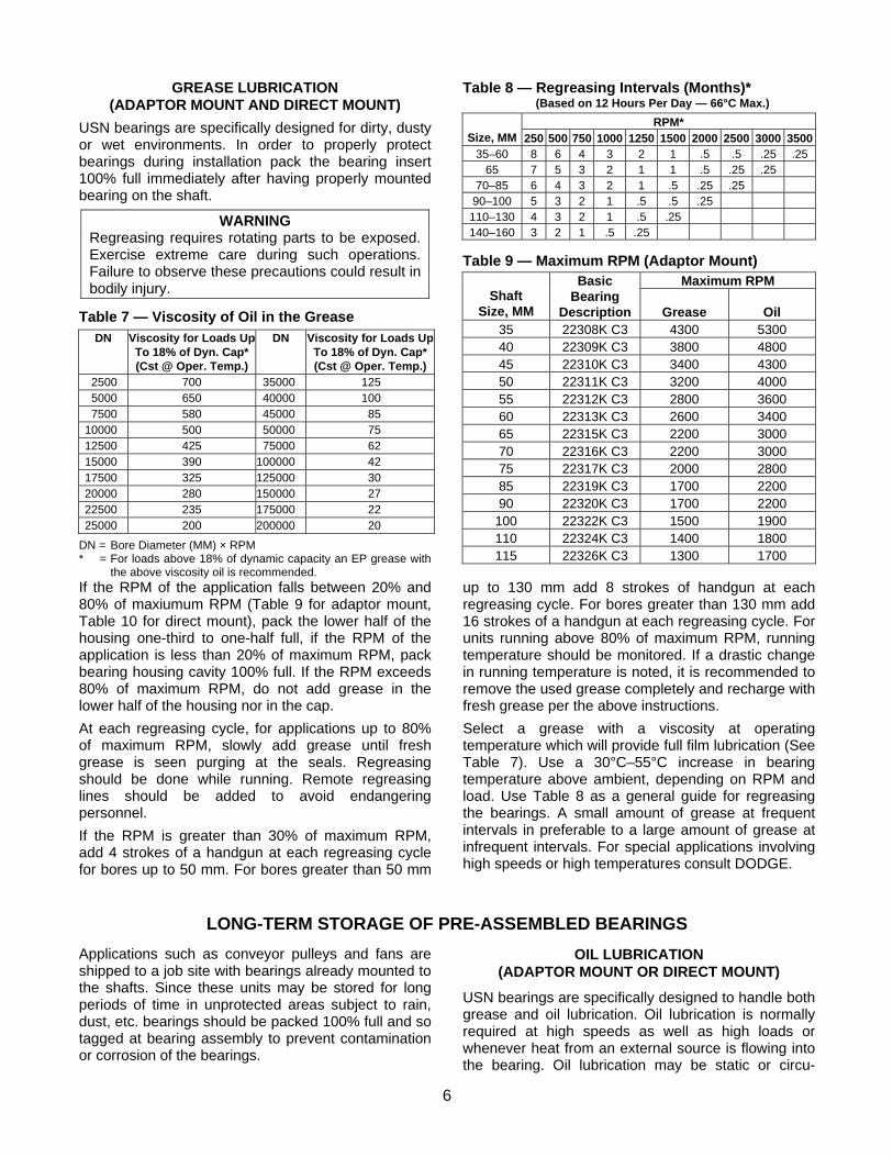
GREASE LUBRICATION (ADAPTOR MOUNT AND DIRECT MOUNT)
USN bearings are specifically designed for dirty, dusty or wet environments. In order to properly protect bearings during installation pack the bearing insert 100% full immediately after having properly mounted bearing on the shaft.
WARNING Regreasing requires rotating parts to be exposed. Exercise extreme care during such operations. Failure to observe these precautions could result in bodily injury.
Table 7 — Viscosity of Oil in the Grease DN Viscosity for Loads Up
To 18% of Dyn. Cap* (Cst @ Oper. Temp.)
DN Viscosity for Loads UpTo 18% of Dyn. Cap* (Cst @ Oper. Temp.)
2500 700 35000 125 5000 650 40000 100 7500 580 45000 85
10000 500 50000 75 12500 425 75000 62 15000 390 100000 42 17500 325 125000 30 20000 280 150000 27 22500 235 175000 22 25000 200 200000 20
DN = Bore Diameter (MM) × RPM * = For loads above 18% of dynamic capacity an EP grease with
the above viscosity oil is recommended.
Table 8 — Regreasing Intervals (Months)* (Based on 12 Hours Per Day — 66°C Max.)
RPM* Size, MM 250 500 750 1000 1250 1500 2000 2500 3000 3500
35–60 8 6 4 3 2 1 .5 .5 .25 .25 65 7 5 3 2 1 1 .5 .25 .25
70–85 6 4 3 2 1 .5 .25 .25 90–100 5 3 2 1 .5 .5 .25
110–130 4 3 2 1 .5 .25 140–160 3 2 1 .5 .25
Table 9 — Maximum RPM (Adaptor Mount) Maximum RPM
Shaft Size, MM
Basic Bearing
Description Grease Oil 35 22308K C3 4300 5300 40 22309K C3 3800 4800 45 22310K C3 3400 4300 50 22311K C3 3200 4000 55 22312K C3 2800 3600 60 22313K C3 2600 3400 65 22315K C3 2200 3000 70 22316K C3 2200 3000 75 22317K C3 2000 2800 85 22319K C3 1700 2200 90 22320K C3 1700 2200
100 22322K C3 1500 1900 110 22324K C3 1400 1800 115 22326K C3 1300 1700
If the RPM of the application falls between 20% and 80% of maxiumum RPM (Table 9 for adaptor mount, Table 10 for direct mount), pack the lower half of the housing one-third to one-half full, if the RPM of the application is less than 20% of maximum RPM, pack bearing housing cavity 100% full. If the RPM exceeds 80% of maximum RPM, do not add grease in the lower half of the housing nor in the cap.
At each regreasing cycle, for applications up to 80% of maximum RPM, slowly add grease until fresh grease is seen purging at the seals. Regreasing should be done while running. Remote regreasing lines should be added to avoid endangering personnel.
If the RPM is greater than 30% of maximum RPM, add 4 strokes of a handgun at each regreasing cycle for bores up to 50 mm. For bores greater than 50 mm
up to 130 mm add 8 strokes of handgun at each regreasing cycle. For bores greater than 130 mm add 16 strokes of a handgun at each regreasing cycle. For units running above 80% of maximum RPM, running temperature should be monitored. If a drastic change in running temperature is noted, it is recommended to remove the used grease completely and recharge with fresh grease per the above instructions.
Select a grease with a viscosity at operating temperature which will provide full film lubrication (See Table 7). Use a 30°C–55°C increase in bearing temperature above ambient, depending on RPM and load. Use Table 8 as a general guide for regreasing the bearings. A small amount of grease at frequent intervals in preferable to a large amount of grease at infrequent intervals. For special applications involving high speeds or high temperatures consult DODGE.
LONG-TERM STORAGE OF PRE-ASSEMBLED BEARINGS
Applications such as conveyor pulleys and fans are shipped to a job site with bearings already mounted to the shafts. Since these units may be stored for long periods of time in unprotected areas subject to rain, dust, etc. bearings should be packed 100% full and so tagged at bearing assembly to prevent contamination or corrosion of the bearings.
OIL LUBRICATION (ADAPTOR MOUNT OR DIRECT MOUNT)
USN bearings are specifically designed to handle both grease and oil lubrication. Oil lubrication is normally required at high speeds as well as high loads or whenever heat from an external source is flowing into the bearing. Oil lubrication may be static or circu-

7
lating. With static oil, fill the bearing cavity with oil up to the centerline of the lower roller. The dimension is identified as "w" and is shown on Table 12. Mount an oil sight gauge on the drilled and tapped drain hole on the side of the plummer block for visual indication of this level. The oil level may drop or rise during operation depending on the rotation of the bearing. Oil should only be added when the bearing is not operating. Both the static oil level and the running oil level should be marked on the oil sight gauge and properly identified.
Prior to installation on the structure, if the application RPM is greater than 20% of catalog maximum speed, excess grease must be removed to the levels outlined previously. Removal of excess grease must be done in a clean, protected environment.
For circulating oil, the flow rate and size of return drains are shown in Table 12. Consult DODGE application engineering for recommendations.
Table 10 — Maximum RPM (Direct Mount)
Maximum RPM Brg. Seat Size, MM
Basic Bearing
Description Grease Oil 40 22308 C3 4300 5300 45 22309 C3 3800 4800 50 22310 C3 3400 4300 55 22311 C3 3200 4000 60 22312 C3 2800 3600 65 22313 C3 2600 3400 70 22314 C3 2400 3200 75 22315 C3 2200 3000 80 22316 C3 2200 3000 85 22317 C3 2000 2800 95 22319 C3 1700 2200
100 22320 C3 1700 2200 110 22322 C3 1500 1900 120 22324 C3 1400 1800 130 22326 C3 1300 1700

8
Table 11 — USN PLUMMER BLOCK — Dowel Pin, Lubrication & Mounting Hole Position
J USN
Housing AA BB CC GG1 GG2
G MAX DIA.
JJ1 JJ2 HOLE SIZE
BOLT SIZE
608/308 39 22.5 6.5 135 23 6 160 34 11 M10
609/309 42 25.5 7 170 27 8 200 40 14 M12
610/310 47 25.5 8.5 172 27 8 200 40 14 M12
611/311 47 32.5 8.5 190 32 8 220 48 14 M12
612/312 47.5 31 9 190 32 8 220 48 14 M12
613/313 51.5 35 8 218 35 8 252 52 18 M16
314 52.5 37.5 10.5 218 35 8 252 52 18 M16
615/315 60.5 38 11 240 37 8 280 58 18 M16
616/316 64.5 41.5 13.5 240 37 8 280 58 18 M16
617/317 68.5 43.5 13.5 260 41 8 300 66 18 M16
619/319 71.5 49 15 280 45 8 320 74 18 M16
620/320 79.5 48.5 17.5 290 45 8 330 74 18 M16
622/322 82.5 53 19 325 52 12 370 80 22 M20
624/324 97.5 64.5 20.5 375 60 12 430 100 26 M24
626/326 104 65 23 395 60 12 450 100 26 M24
NOTE: All dimensions are in millimeters Item Description
A Optional seal grease location B Optional location for vent, vibration pickup and/or grease location for non W33 grooved bearing C Position for thermocouple location D Position for lubrication of bearing with W33 groove E Lubrication port for W33 groove, bearing drilled standard on plummer blocks F Drilled and tap location for vent or side lubrication for bearing without W33 groove G Dowel pin location for metric plummer blocks J Drilling location for four bolt mounting or optional dowel pin location
Table 12 — USN Circulating Oil Chart Circulating Oil Flow*
Amount Sufficient For Normal Lubrication
Maximum Amount For Heat Dissipation Due to External
Heat Source
Static Oil Level/MM Block
Size
Liters/Min. Liters/Min. W**
Drain Holes Size
(BSPP) 608/308 .011 .340 26.5 1/8–28 609/309 .015 .378 32.5 1/8–28 610/310 .017 .454 28.5 1/8–28 611/311 .019 .567 40.5 1/8–28 612/312 .023 .662 30.5 1/4–19 613/313 .025 .738 42 1/4–19
314 .028 .757 37 3/8–19 615/315 .030 .946 42 3/8–19 616/316 .038 1.135 47 3/8–19 617/317 .042 1.324 42 3/8–19 619/319 .057 1.590 45 3/8–19 620/320 .066 1.816 58 1/2–14 622/322 .072 2.080 58.5 ½–14 624/324 .095 2.830 60 ½–14 626/326 .113 3.030 62 ½–14

9
SKETCH 1
REPLACEMENT PARTS FOR USN PLUMMER BLOCKS
USN 600 Adaptor Mounted Plummer Blocks Ref. Name of
Part Style Qty. (608)
35(609)
40(610)
45(611)
50(612)
55(613)
60(615)
65(616)
70(617)
75(619)
85(620)
90(622) 100
(624) 110
(626) 115
12 2-Bolt Base Housing Standard 1 035792 035795 035797 035799 035801 035803 035805 035807 035809 035812 035814 035816 035818 03582012 2-Bolt Base Housing Closed End 1 035794 035796 035798 035800 035802 035804 035806 035808 035810 035813 035815 035817 035819 03582121 Roller Bearing 1 423375 423100 423372 423102 423376 423104 423106 423373 423108 423374 423110 423112 422140 423114
091640981640881640 143640 845640 481640381640833640181640745640971640633640 533640 645640 2 *gniR laeS 61332240332240132240 569540 032240 922240822240499540622240622240522240279040 422240 342240 2 *gniR-V 71
20 Adaptor Sleeve 1 046652 046653 046654 046655 046656 046657 046658 046659 046660 046661 046662 046663 046664 046665692640592640492640 392640 884640 192640092640982640882640784640782640682640 582640 294640 1 tuN 22513640413640313640 213640 094640 013640903640803640703640984640603640503640 403640 394640 1 rehsawkcoL 42
26 Drain Plug Std. & Closed End 2 415480 415480 415480 415480 415481 415481 415482 415482 415482 415482 415483 415483 415483 415483106504106504106504 106504 106504 106504106504106504106504106504106504106504 106504 106504 1 gnittiF ebuL 41
18 Non-Expansion Spacer 1 042335 042315 046642 042316 460886 460887 460889 046643 460890 460891 460892 460635 042341 460896 )seziS llA( 974514 1 gulP poT 52
*Closed end housings lake only one seal ring and one V-ring.
SKETCH 3 REPLACEMENT PARTS FOR USN PLUMMER BLOCKS
USN 300 Direct Mounted Plummer Blocks Ref.
Name of Part Style Qty.
(308) 40
(309) 45
(310) 50
(311) 55
(312) 60
(313) 65
(314) 70
(315) 75
(316) 80
(317) 85
(319) 95
(320) 100
(322) 110
(324) 120
(326) 130
12 2-Bolt Base Housing Standard 1 035822 035824 035826 035828 035830 035832 035834 035836 035838 035840 035842 035844 035846 035848 03585012 2-Bolt Base Housing Closed End 1 035823 035825 035827 035829 035831 035833 035835 035837 035839 035841 035843 035845 035847 035849 03585121 Roller Bearing 1 423124 423125 423123 423126 423127 423128 423129 423130 423144 423131 423145 423132 423133 423134 42313516 Seal Ring* 2 046179 035743 046181 046338 046183 046340 046549 039518 046341 046342 046189 046190 046191 046192 045990
632240532240432240 332240 232240 132240569540032240032240922240822240499540622240279040 522240 2 *gnir-V 71692640592640492640 392640 884640 192640092640982640832640882640784640782640682640582640 294640 1 tuN 22
24 Lockwasher 1 046493 046304 046305 046306 046489 046307 046239 046308 046309 046310 046490 046312 046313 046314 04631526 Drain Plug Std. & Closed End 2 415480 415480 415480 415480 415481 415481 415482 415482 415482 415482 415482 415483 415483 415483 41548314 Lube Fitting 1 405601 405601 405601 405601 405601 405601 405601 405601 405601 405601 405601 405601 405601 405601 405601
18 Non-Expansion Spacer 1 042335 042315 046642 042316 460886 460887 460888 460889 046643 460890 460891 460892 046635 042314 460896
)seziS llA( 974541 1 gulP poT 52 )4 egap no d2 hpargaraP eeS( eveelS 13
* Closed end housings take only one seal ring find one V-ring.

10

World HeadquartersP.O. Box 2400, Fort Smith, AR 72902-2400 U.S.A., Ph: (1) 479.646.4711, Fax (1) 479.648.5792, International Fax (1) 479.648.5895
Dodge Product Support6040 Ponders Court, Greenville, SC 29615-4617 U.S.A., Ph: (1) 864.297.4800, Fax: (1) 864.281.2433
www.baldor.com
© Baldor Electric Company All Rights Reserved. Printed in USA.
MN3023(Replaces 499809)
06/30/09*3023-0609*