
INSTRUCTION MANUAL Flight Light, Inc. ZA737/757 PRECISION ... · Flight Light, Inc. ZA737/757....
38
INSTRUCTION MANUAL Flight Light, Inc. ZA737/757 PRECISION APPROACH PATH INDICATOR (STYLE A) Revision:C 05/30/2013 For Spare Parts or Technical Assistance, Call: Flight Light, Inc. 2708 47 TH Ave. Sacramento, CA 95822 (916) 394-2800 (916) 394-2809 (fax) E-mail: [email protected] See: www.flightlight.com for complete catalog.
Transcript of INSTRUCTION MANUAL Flight Light, Inc. ZA737/757 PRECISION ... · Flight Light, Inc. ZA737/757....

INSTRUCTION MANUAL
Flight Light, Inc. ZA737/757 PRECISION APPROACH PATH INDICATOR (STYLE A)
Revision:C 05/30/2013
For Spare Parts or Technical Assistance, Call:
Flight Light, Inc. 2708 47TH Ave.
Sacramento, CA 95822 (916) 394-2800
(916) 394-2809 (fax) E-mail: [email protected]
See: www.flightlight.com for complete catalog.
Eliana.Rodriguez
Typewritten Text
1

INSTRUCTION MANUAL INDEX
1.00 INSTALLATION INSTRUCTIONS 1.10 Proper Light Box Location...................................... 5 1.20 Interconnect Wiring and Home Runs.................... 5 1.21 Wiring Sizing……………………………………. 5 1.22 Wiring Protection………………………………... 5 1.23 Wiring Connections…………………….………… 5 1.30 Adjustment of the Light Box Assembly.... ............ 6 1.31 L881 (two box system)….……………………….. 6 1.32 L880 (four box system)…………………………. 7 1.40 Color Filter Installation and Electrical Adjustments 8 1.41 Lamp Installation………………………………….. 8 1.42 Interlock Adjustment……………………………… 9 1.50 Flight Check............................................................ 9
2.00 SYSTEM DESCRIPTION AND COMPONENTS
2.10 Light Housing Assembly...................................... 9 2.20 Power Adapter....................................................... 9 2.30 Day/Night Brightness Control.............................. 10 2.40 Power Regulation Circuit...................................... 10 2.50 Tilt Detection Circuit ........................................... 10 2.60 Lens Heater Circuit .............................................. 11 2.70 Alignment & Aiming Device Calibration............ 12 2.80 Runway Interlock (optional) ……………………. 13
Eliana.Rodriguez
Typewritten Text
2

3.00 SITING AND AIMING
3.10 Signal Presentation.............................................. 13 3.20 General Siting Considerations.. ......................... 13 3.30 Siting PAPI on a Runway w/ ILS glide slope..... 13 3.40 Siting PAPI on a Runway w/o ILS glide slope... 13 3.41 Threshold Crossing Height (TCH)…………….. 14 3.42 Glide Path Angle………………………………. 14 3.43 The PAPI Obstacle Clearance Surface………… 14 3.50 Aiming ................................................................ 14 3.60 Other Siting Dimensions & Tolerances.............. 14 3.61 Distances From Runway Edge………………… 14 3.62 Separation Between Light Units………………. 15 3.63 Azimuth Aiming………………………………. 15 3.64 Mounting Height Tolerances………………….. 15 3.65 Tolerance Along Line Perpendicular………….. 15 3.66 Correction for Runway Longitudinal Gradient... 15 3.67 Other Site Considerations……………………… 15 3.70 Siting Typical Two Box System.......................... 15
Abbreviations………………………………….. 15
4.00 TROUBLESHOOTING............................................ 16
5.0 DRAWINGS & ADDENDUMS (attached)
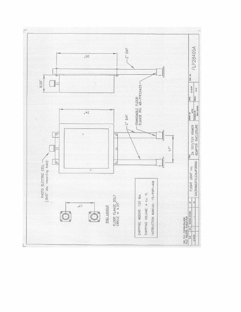
5.1.0 ZA757/737 Power Adapter parts layout (FLP28400J), Class I & II…….…17 5.2.0 ZA757 Power Adapter wiring diagram (FLP28401E) (50/60Hz) …….…18 5.2.1 ZA757 Power Adapter wiring diagram (FLP28401G)with Interlock ….…19 5.2.2 ZA737 Power Adapter wiring diagram (FLP28401K) ……………….…..20 5.2.3 ZA737 Power Adapter wiring diagram (FLP28401H) ………………….21 5.2.4 ZA757 Power Adapter wiring diagram - Interlock option (FLP28401G-2) 22 5.3.0 ZA757 Installation wiring diagram (FLP28403H)…………………………23 5.3.1 ZA737 Installation wiring diagram (FLP28403I) …………………….24 5.4.0 ZA757 LHA Wiring diagram (FLP1006A) Class I………………………..25 5.6.1 ZA737 LHA Wiring diagram (FLP1006B) Class I …………………………26 5.7.0 ZA757 LHA Wiring diagram (FLP28404D) Class II ……… …………… 27 5.7.1 ZA737 LHA Wiring diagram (FLP28404H) Class II …………………….. 28 5.8.0 Power Adapter Enclosure (FLP28405A) ……………………………….……29 5.8.1 Frangible mounting accessories (FLP28406B)……………………………....30 5.9.0 ZA757 Base Mounting Guide (FLP28407A) ……………………………….31 5.9.1 ZA737 Base Mounting Guide (FLP28407B) ……………………………….32 5.9.2 ZA757 Filter Installation (FLP28408)……………………………………….33 5.9.3 ZA737 Filter Installation (FLP28408A) ……………………………………34
Eliana.Rodriguez
Typewritten Text
3

6.0 PARTS LIST …………………………………………………… ………………..35-38
Eliana.Rodriguez
Typewritten Text
4
SECTION ONE INSTALLATION INSTRUCTIONS
1.00 Installation: The ZA737/757 PAPI system requires several steps to insure proper installation and maximum performance.
These steps should not be bypassed.
* Determination of proper location of the light boxes. * Installation of the footers and mounting pads. * Interconnect wiring and home run wiring. * Alignment of the light box assemblies. * Electrical adjustments. * Flight check.
1.10 Determination of Proper Light Boxes
To obtain an optimized approach system, several factors must be considered. These are: * What is the distance between the pilot's eyes and the wheel of the largest aircraft to use the runway? * What is the desired threshold crossing height? * What is the desired glide slope angle? * Will the selection of the above parameters satisfy the required obstacle clearance angle?
1.20 Interconnect Wiring and Home Runs
1.21 The home run wiring size should be carefully selected to insure optimum performance of the system.
Select the size as indicated by plans and specifications. If the power unit is located within 30' of the light box, #10 wire is adequate for the lamp circuit, and #14 wire is adequate for the tilt switch circuit.
1.22 To protect the wiring between the light box assembly and the point at which it goes underground, 1" watertight flex duct is a good selection. It can be terminated in a 1" conduct (pipe) sweep to interface to the trench.
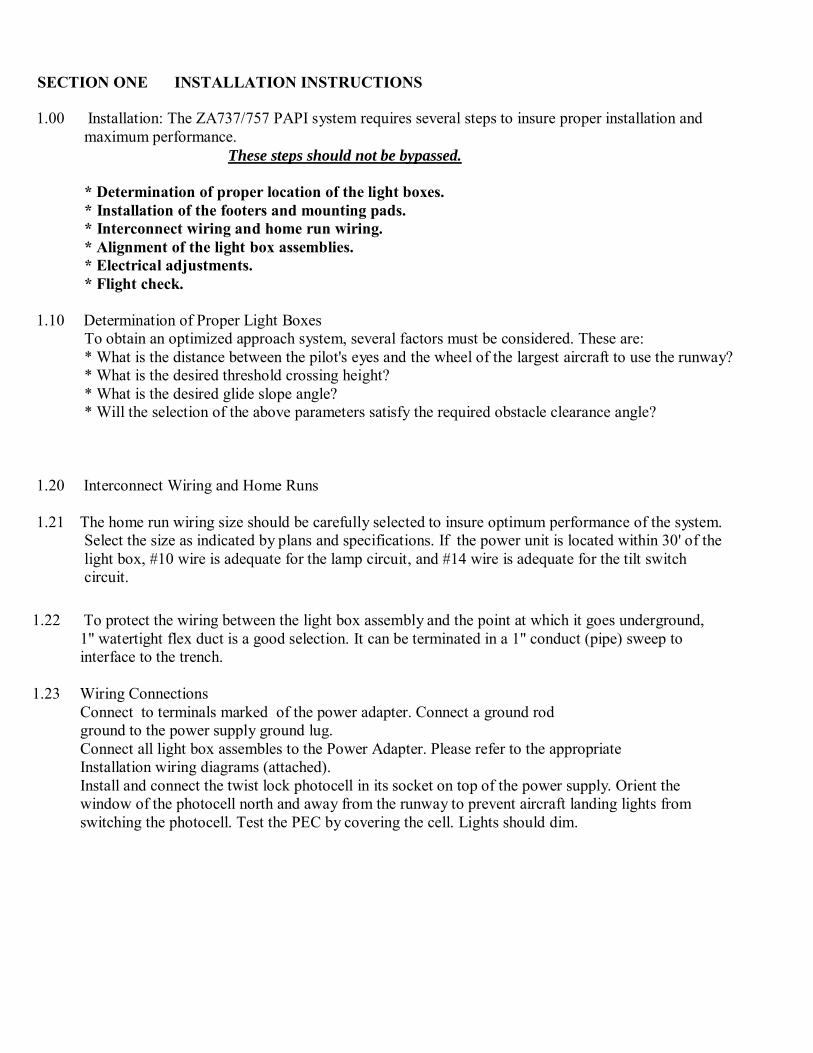
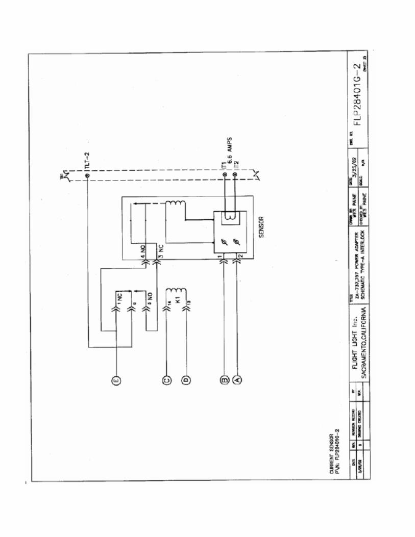
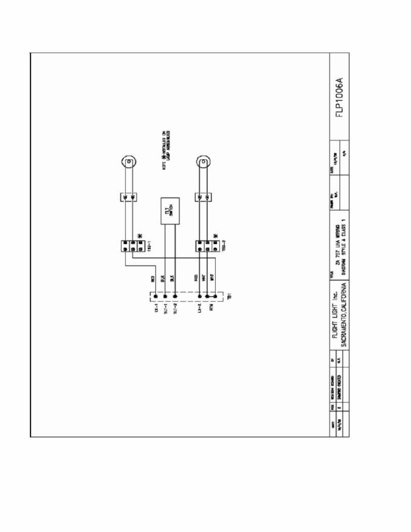
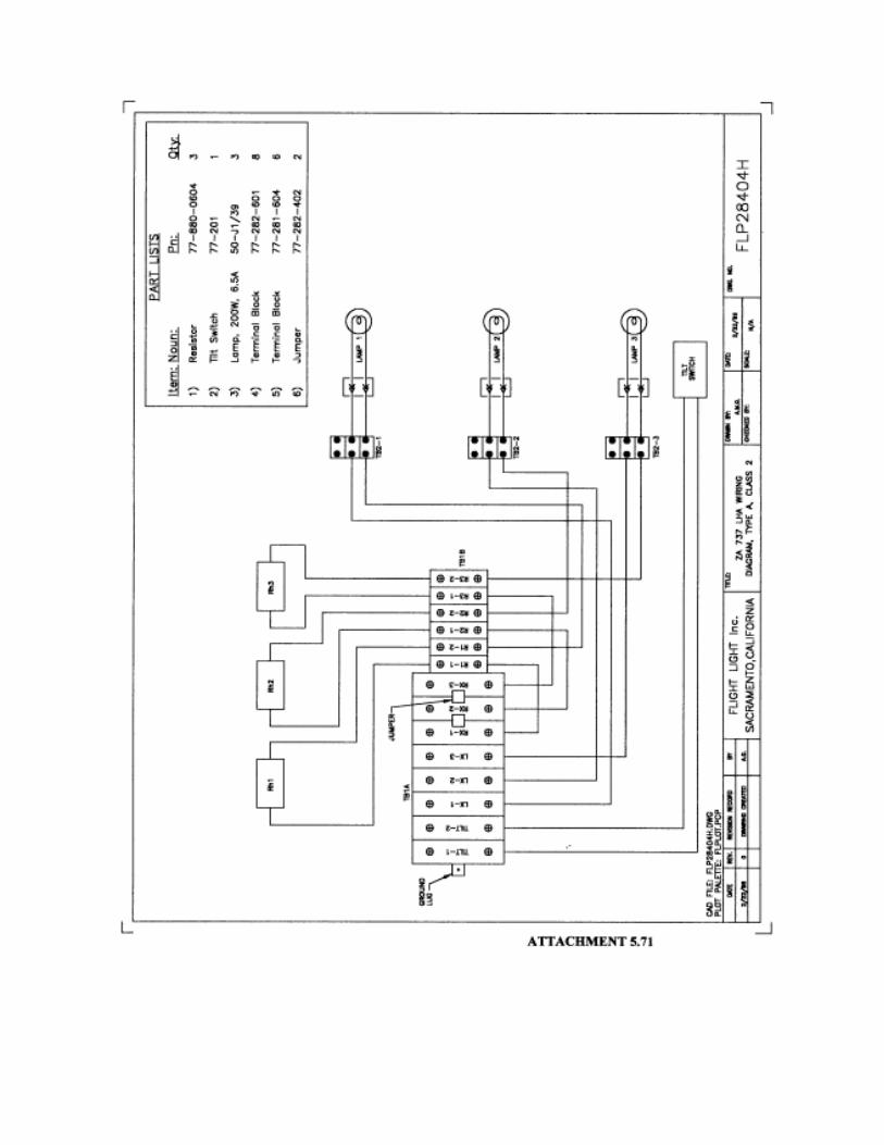
1.23 Wiring Connections
Connect to terminals marked of the power adapter. Connect a ground rod ground to the power supply ground lug. Connect all light box assembles to the Power Adapter. Please refer to the appropriate Installation wiring diagrams (attached). Install and connect the twist lock photocell in its socket on top of the power supply. Orient the window of the photocell north and away from the runway to prevent aircraft landing lights from switching the photocell. Test the PEC by covering the cell. Lights should dim.
Eliana.Rodriguez
Typewritten Text
5

1.30 Adjustment of the Light Box Assemblies
The Aiming Device consists of precision machined aluminum block corresponding to the particular angles required by Glide Slope and number of boxes. There are 5 blocks for a four box system and 3 blocks for a two box system with standard Glide Slope of 3 degrees. Non-standard Glide Slopes will require special sets of aiming blocks. The Aiming Blocks are designed to be set on the edge of the light box with the provided spirit level on the top surface. Refer to Figs. 1 & 2
Figure 1 - Aiming device positioning. 1.31 L-881 (two box system)
The light box assembly nearest the runway should be adjusted to the glide slope angle + 1/4 degree ( +15 minutes). The light box assembly farthest from the runway should be adjusted to the glide slope angle - 1/4 degree (-15 minutes). When the boxes are in place, make sure both are adjusted with the adjustment jacks so that the center of the lens of the boxes are at the same elevation. Remove the cover from the light box assembly. For horizontal alignment place the 6" spirit level across the light box, either on the lens housing or reflector housing. Adjust the forward nuts on the adjustment jacks to bring the spirit level to center.
Eliana.Rodriguez
Typewritten Text
6

HINT! For each 1/4 turn executed on the nut on one side, turn the nut on the other side 1/4 turn in the opposite direction. This will keep the lens center at the same elevation at all times during adjustment. recheck both points. Position the proper aiming block on the edge of the light box for vertical alignment. Place the spirit level on the aiming block. Adjust the both rear adjustment jacks to bring the spirit level to center. Next, tighten the bolts holding the pivots. These are accessible underneath the unit at the forward corners. Recheck the horizontal adjustment at points at each corner and adjust as required. Tighten all nuts securely. Recheck the vertical adjustment, then tighten all nuts on the new pivot. Last, place the level on top of the tilt switch. Adjust the tilt switch until the spirit level is centered. Tighten the bolts to hold the tilt switch secure. Replace the cover on the light box assembly.
1.32 L-880 (four box system)
The light boxes: Assembly nearest the runway should be adjusted to the glide slope angle + 1/2 degree. The next adjacent light box assembly should be adjusted to the glide slope angle + 1/6 degree. The next adjacent light box assembly should be adjusted to the glide slope angle - 1/6 degree. The next adjacent light box assembly should be adjusted to the glide slope angle - 1/2 degree. When the boxes are in place, make sure both boxes are adjusted with the adjustment jacks so that the center of the lens of all boxes are at the same elevation. Remove the cover from the light box assembly. For horizontal alignment place the 6" spirit level across the light box, either on the lens baffle or reflector baffle. Adjust the forward nuts on the adjustment jacks to bring the spirit level to center.
HINT! For each 1/4 turn executed on the nut on one side, turn the nut on the other side 1/4 turn in the opposite direction. This will keep the lens center at the same elevation at all times during adjustment. Recheck both points. Position the proper aiming block on the edge of the light box for vertical alignment. Place the spirit level on the aiming block. Adjust the both rear adjustment jacks to bring the spirit level to center. Next, tighten the bolts holding the pivots. These are accessible underneath the unit at the forward corners. Tighten all nuts securely. Recheck the horizontal adjustment and adjust as required. Recheck the vertical adjustment, then tighten all nuts on the new pivot. Last, place the level on top of the tilt switch. Adjust the tilt switch until the spirit level is centered. Tighten the bolts to hold the tilt switch secure. Replace the cover on the light box assembly.
Eliana.Rodriguez
Typewritten Text
7

Figure 2 - Spirit level placed on aiming device.
1.40 Color Filter Installation and Electrical Adjustments When installing the color filters, as viewed from the rear, select the indicated serial numbered filter set and install so that “TCR” is positioned top, center,(toward the center of the light box) and to the rear. This is marked on each color filter. After each light box assembly has been properly aligned, and the tilt switches properly set, the system is ready to be turned on. Apply power to the system and energize the circuit breaker (CB1) in the Power Supply. The lamps in all light boxes should now be ‘ON’.
CAUTION!
Do not look directly into the front of the light box because the
light beam is very intense at that point.
Assuming it is daytime, the power supply should be adjusted to produce approximately 6.6 amps of current as read on the amp meter in the power adapter. If the amp meter reads less than 6.6 amps, turn the circuit breaker ‘OFF’. Move the input to TB2-5 to the next lower numbered terminal, i.e. change from #5 to #4 would increase the amperage. At night the amperage should be 4.8 amperes. Turn the circuit breaker ‘ON’. check the amp meter for 6.6 amps. Continue this procedure until the current is as close to 6.6 amps as possible, but in no case, exceeding 6.6 amp. Clean out the residue from the power supply and neatly dress the wiring. Be sure that all light boxes and the power supply are connected to ground rod ground. Close the door of the power supply and secure it’s latch.
1.41 Lamp Installation-Install LA-6373 lamps into each light box assembly’s lamp holder.
CAUTION!
Eliana.Rodriguez
Typewritten Text
8

Do not touch the quartz tube of the LA-6373 lamp as finger oils will
significantly reduce lamp life. If touched, clean with rubbing alcohol.
1.42 Interlock Adjustment, set in over-current mode (optional feature only) The current monitor is set at the factory to turn on when the current being sensed rises to a level greater than 6.3 amps after a time delay. This internal delay may require adjustment based upon airfield operational requirements, but set to minimum unless advised otherwise. Apply power to the runway lights at the required operational step. Fine-tune the trip point by turning the adjustment and watching the LED. The LED will light indicating over-current. When a over-current is sensed (LED ON), the output relay is energized. This is the normal state when the runway lights are energized.
1.50 Flight Check
Before placing in service, the system should be thoroughly flight checked. The flight check should include flying over any and all obstructions in the approach area to be sure that all light boxes show red whenever you are close to the obstructions. Several normal approaches should be made to insure good signal at all points in the approach path.
WARNING!
Turning the circuit breaker (CB1) to ‘OFF’ does NOT remove All voltages. TB1, SA1/2, and CB1are still ‘HOT’!
SECTION TWO SYSTEM DESCRIPTION 2.00 Principle Components
The model ZAZ737/757 PAPI ‘A’ Style system consists of the following principle components: Light Box Assemblies (Qty 4 for L880; 2 for L881) 1 ea. - Power Adapter 1 lot - Mounting Hardware 1 ea. - Aiming Device with precision 6" Spirit Level. A protective case is included with each device.
2.10 Light Housing Assembly
The light box assembly is stable optical platform which supports the lamp, Reflector, lenses, color filter, and tilt switch. Light from the lamp is collected and focused into the plano-convex lens set. This combination produces the field of illumination into the approach area. Concurrent with the illumination, a red filter is so located that it is at the focal point of the plano-convex lens set as one would view the light box from the approach area. The transitions zone is factory adjusted so that it agrees with the calibrated scale on the alignment arrow assembly. When the light box assembly is being adjusted, the process elevates the front of the light box assembly so that the transition zone is set to the desired angle of inclination (alignment angle). It is extremely important that when the light box assembly is aligned in the field, all bolts and nuts are tightened properly, then alignment rechecked to insure accuracy. Lamp is Flight Light PN: LA-J1/39
2.20 Power Adapter
Eliana.Rodriguez
Typewritten Text
9

The power adapter assembly converts the 220 to 240 VAC (@ 50 or 60Hz) into 6.6 amperes to operate the lamps. This is accomplished by transformers T1 (and T2 in a 4 box system) which also provides a lower amperage taps so that the lamps can be dimmed for nighttime service. Following is a description of the purpose of the main components in the power supply:
SA1/2 Provides basic lightning surge protection of the 220-240 VAC input. CB1 Circuit over current protection and ON/OFF switch. T1(T2) Power transformer(s): reduces the 220-240 VAC to acceptable required
voltages while providing adjustments to lamp brightness. PEC Photo Electric Controller: detects night or day condition and provides signal
(1=night, 0=day). RTE-P21 Tilt failure detector and delay timer - adjustable - set to 30 seconds in factory. M1 0 - 10 Meter: provides visual indication of lamp current and assists in prevention
of over-driving the lamps. It’s accuracy is 2%. CR1 & CR2 Lamp intensity step-down relay: Energized during low light levels. CR3 & CR4 Lamp/tilt circuit control element - normally energized. Tilt failures de-energize
this unit with delay set by RTE-P21. This turns OFF all lamps. Monitor This is an optional unit used to provide interlock to runway lighting circuits. K1 Control relay for optional interlock control. PS1 Power supply for stable timer and monitor operation.
2.30 Day/Night Control
By utilizing a PEC and a DPST relay, the controller can automatically switch between two different brightness levels depending on ambient light levels. This in essence provides day/night brightness levels. During daylight the PEC’s output will be de-energized. Relays CR1 and CR2 will be
2.30 Day/Night Control(cont)
de-energized. During night operation, the PEC’s output is energized which in turn energizes the relays CR1 and CR2. Minimum rated current is supplied to the lamps from T1/T2. This reduced lamp current (4.8A)/intensity insures pilot safety and convenience. By design in the event of component failure, the system will default to the night brightness level for insured aircraft safety or shut down completely with tilt failures.
2.40 Power Regulation Circuit
The power regulation circuit consists of a 15 amp circuit breaker, and multi-tap transformers (T1 and T2). In operation CB1 acts as the ON/OFF switch while providing circuit over-current protection. SA1 and SA2 provides basic lightning surge protection to the entire unit. The multi-tap power transformer(s) allows adjustment of both the day and night brightness levels via the taps on the secondary side.
2.50 Tilt Detection Circuit
To insure aircraft safety by preventing out-of-alignment systems from operating, a tilt detection circuit has been incorporated into the controller. This circuit utilizes a time delay feature to screen out false signals due to vibrations. In normal operation with a closed tilt loop switch-loop,
NOTE: BOTH RTE-P21 LEDS WILL BE ‘ON’.
Eliana.Rodriguez
Typewritten Text
Eliana.Rodriguez
Typewritten Text
10

Should the tilt circuit fail, the Mode LED (top) will extinguish after the delay period which was factory adjusted to 30 seconds. At no time should this or any other safety feature be bypassed or modified. To do so will risk aircraft safety.
2.60 Lens Heater Circuit, Class II only
In severe winter climates, the lens must be heated to insure dependable operation in all weather conditions. This is accomplished by a power resistor in series with each lamp filament. It dissipates approximately 20 watts into its heater mount; this insures complete lens heat absorption and dependable signal presentation to pilots.
2.70 Alignment & Aiming Device Calibration
This component has two parts. The structural component shown in Figure 2 has no calibration. It has been factory checked for accuracy and cannot be altered without damage to the frame. The adjustable precision spirit level is shown in Figure 3. The level was factory aligned and should not require adjustment, but if this were ever necessary, the check and alignment is quite simple: A. Use any flat level surface - the more level and stable the better. Insure the surface is clean, and that the bottom of the level is also clean. B. Place the level on the inspected area, marking its location. Now, reverse the level (turn it 180 degrees). The bubble MUST be in the same relative position on the scale. C. With each movement of the level, give the bubble time to become stable. D. Should the bubble NOT be in the same relative position, loosen the adjustment nuts and correct for one-half of the difference in the readings. Re-tighten the nuts. Repeat steps B, C, and D until there is no difference. This completes the Alignment and Aiming Device’s calibration. It should be accomplished before each use, or at least semi-annually.
2.80 Runway Interlock (optional) The Monitor senses the current flowing in the connected runway circuit. The logic of it operation is as follows:
Daylight: Runway Lights: PAPI Lamps On?
Yes On Yes
Yes
Off
Yes
No
On
Yes
No
Off
No
Since it controls the Power Adapter by interrupting the tilt switch circuit, the tilt switch timer’s delay must be considered when testing or troubleshooting. Please refer to FLP28401D and FLP28401C, sheets 1 and 2 (attached).
Eliana.Rodriguez
Typewritten Text
11

-.
lJ= c=::::J
3
MECHANICAL 36" dia.
[IDJ
MOUNTING
HOLES (2)
0.188"
3.5" 2.94" 1
c=::::J
2 c:::==
0
0.25" QUICK-CONNECT
k--.79"-J
L1.64" max. .
2.5"
5 TERMINALS (5)
Eliana.Rodriguez
Typewritten Text
12

SECTION THREE SIGNAL PRESENTATION AND SITE CONSIDERATIONS
3.10 Signal Presentation
The precision approach path indicator (PAPI) is a system of either four or two identical light housing assemblies or “light units” placed on the left of the runway aimed outward into the approach zone on a line parallel to the runway. The front face of each unit is perpendicular to the runway centerline. The boxes are positioned and aimed to produce the signal presentation described below.
A. L-880 “Four Box System”: When making an approach, the pilot will:
(1) When on or close to the established approach path, see the two units nearest the runway as red and the two units farthest from the runway as white; and (2) When above the approach path, see the unit nearest the runway as red and the three units farthest from the runway as white; and when further above the approach path see all the units as white; and (3) When below the approach path, see the three units nearest the runway as red and the unit farthest from the runway as white; and when further below the approach path see all units as red.
B. L-881 “Two Box System”: when making an approach, the pilot will:
(1) When on or close to the established approach path, see the unit nearest the runway as red and the other unit as white; and (2) When above the approach path, see both units as white; and (3) When below the approach path, see both units as red.
PAPI SIGNAL PRESENTATION
3.20 General Site Considerations
When viewed from the approach end, the PAPI system shall be located on the left side of the runway. In the event of siting problems, such as conflicts with runways or taxiways, the PAPI may be located on the right side of the runway. The PAPI must be sited and aimed so that it defines an approach path with adequate clearance over obstacles and a minimum threshold crossing height (“TCH”). If the runway has an Instrument Landing System (ILS) Glide slope already established, the PAPI is installed as described in 1.3 below so that the visual Glideslope will coincide (as much as possible) with the electronic one produced by the ILS. If there is no ILS on the runway, the PAPI Glideslope is chosen as described in 1.4 below. Aiming of the light units is described at 1.50. Other siting tolerances and considerations which are common to all PAPI installations are described at 1.6.
3.30 PAPI site on a Runway With an ILS glide slope
When the PAPI site is on a runway with an established ILS glide slope, the PAPI visual approach path should coincide as much as possible with the one produced electronically by the ILS. To accomplish this, the PAPI is placed at the same distance from the threshold as the virtual source of the ILS glide slope within a tolerance of +/- 30 feet (+/- l0m). The PAPI is aimed at the same angle as the ILS glide slope. For these locations, the distance to the ILS glide slope source plus an additional 300 feet +50, -0 (90m + 15, -0).
3.40 PAPI site on a Runway Without an ILS glide slope
When an ILS glide slope is not present, the designer must determine a position and aiming for the PAPI which will produce the required threshold crossing height and clearance over obstacles in the approach area.
Eliana.Rodriguez
Typewritten Text
13

3.41 Threshold Crossing Height (TCH) The TCH is the height of the lowest on-course signal at a point directly above the intersection of the runway centerline and the threshold. The minimum allowable TCH varies according to the height group of aircraft that uses the runway. The PAPI approach path must provide the proper TCH for the most demanding height group that uses the runway.
3.42 Glide Path Angle
The visual glide path angle is the center of the on-course zone, and is normally 3 degrees when measured from horizontal. For non-jet runways, this may be raised to 4 degrees if required to provide obstacle clearance. If used, the higher angle must be specified in a Notice to Airmen (NOTAM) and published in the Airport Facility Directory.
3.43 The PAPI Obstacle Clearance Surface
The PAPI obstacle clearance surface is established to provide the pilot with a minimum clearance over obstacles during approach. The PAPI must be positioned and aimed so that no obstacles penetrate this surface. The surface begins 300 feet (90m) in front of the PAPI system (closer to the threshold) and proceeds outward into the approach zone at an angle 1 degree less than the aiming angle of the third light unit from the runway (L-880, Four Box System), or the outside light unit (L- 881, Two Box System). For a L-880 with a 3 degree glide path and 20 minute separation between light units, the third light unit from the runway would be aimed at 2 degree 50' elevation. The surface extends 10 degrees on either side of the runway centerline extended, and extends 4 statute miles from its point of origin. If a site survey determines that there is an obstacle which penetrates the obstacle clearance surface, and cannot be moved, then the glide path angle must be changed or the PAPI system moved further from the threshold. By moving or re-aiming the PAPI, the designer must reposition the PAPI obstacle clearance surface so it will not be penetrated by an obstacle.
3.50 Aiming
After the visual glide path angle has been selected, the PAPI units are aimed to define that path. The standard aiming angles for the L-880 (4-Box) and the L-881 (2-Box) systems are shown in Tables 2 and 3 of the FAA CIRCULAR AC 150/5345-28D dtd. 5/23/85, and are reflected in these instructions.
Table 2. Aiming of the L-880 (4-Box) PAPI Relative to a pre-selected glide path, Chapter 2, par. 20, page 15.
Table 3. Aiming of the L-881 (2-Box) PAPI Relative to a pre-selected glide path, Chapter 2, par. 20, page 15.
3.60 Other Site Dimension and Tolerances
3.61 Distances From Runway Edge
The inboard light unit shall be no closer than 50 feet, +10, -0 (15m, +3, -0) from the runway edge or to other runways or taxiways. This dimension may be reduced to 30 feet (10m) for small general aviation runways used by non-jet aircraft.
Eliana.Rodriguez
Typewritten Text
14

3.62 Separation Between Light Units-The PAPI Units shall have a lateral separation of between 20 and 30 feet (6 to 9m) for a 4-Box system because it increases the usable range of the 4-box system the distance between boxes shall not vary by more than 1 foot (0.3m).
3.63 Azimuth Aiming
Each light unit shall be aimed outward into the approach zone on a line parallel to the runway centerline within a tolerance of +/- 1/2 degree.
3.64 Mounting Height Tolerances
The beam centers of all light units shall be within +/- 1 inch of a horizontal plane. This horizontal plane shall be within +/- 1 foot (0. 3m) of the elevation of the runway centerline at the intercept point of the visual glide path with the runway (except for the condition at 1.67 below).
3.65 Tolerance Along Line Perpendicular to Runway
The front face of each light unit in a bar shall be located on a line perpendicular to the runway centerline within +/- 6 inches.
3.67 Other Site Consideration
(1) Where the terrain drops off rapidly near the approach threshold and severe turbulence is experienced, the PAPI should be located farther from the threshold to keep the aircraft at the maximum possible threshold crossing height. (2) On short runways, the PAPI should be as near the threshold as possible to provide the maximum amount of runway for braking after landing. (3) At locations where snow is likely to obscure the light beams, the light units may be installed so the top of the unit is a maximum of 6 feet (2m) above ground level. This may require locating the light units farther from the runway edge to ensure adequate clearance for the most critical aircraft. Since raising the light units also raises the threshold crossing height for the visual glide path, the lights may also have to be relocated closer to the threshold to remain within specified tolerances.
3.70 Siting the Typical L-881 (2-Box) System
Abbreviations: Dl = ideal (zero gradient) distance from the threshold RWY = Runway longitudinal gradient TCH = Threshold Crossing Height T = Threshold E = Elevation difference between threshold and RRP = Runway reference point (where aiming angle or visual approach path intersects runway profile)
D= Adjusted Distance from Threshold O= Aiming Angle
Eliana.Rodriguez
Typewritten Text
15

SECTION FOUR TROUBLESHOOTING
4.00 Troubleshooting
Very few problems will occur with your system. However, in the case of problems, the following pointers will help you locate and correct the problems. It is assumed that all interconnect wiring is good and that tilt switches are aligned and have continuity. Also, verify 50 or 60Hz power source for operation.
Symptom Likely Problem
CLASS I or CLASS II
Lamp ‘OUT’ Check lamp (if either lamp burns out, it would
not shut off the other lamp). PEC operation reversed Check wiring of PEC toTB3 (color coded (dim in daylight) red/blk/wht).
CLASS II ONLY! Lamp still not ‘ON’ Temporarily short TB1B, R1-1
and R1-2, then R2-1 and R2-2. As each is tested, if the failed lamp turns ‘ON’, the heater resistor may have failed. Check for .5 ohm resistance - replace if required.
CLASS I or CLASS II Lamps do not light Temporarily short Power Supply (RTE-P21 mode light out) TB1 T-1 and TB1 T-2 and engage
CB1. If system now functions, problem is either switches or tilt switch wiring.
If problem is determined to be a particular tilt switch, readjust tilt switch by going through zero and then back.
DO NOT LEAVE JUMPER IN PLACE! Light Box Alignment Footers not stable.
Mounting hardware is not tight. Check floor flanges, nuts on frangible couplings, bolts & nuts on light b
Eliana.Rodriguez
Typewritten Text
16

Eliana.Rodriguez
Typewritten Text
17

Eliana.Rodriguez
Typewritten Text
18

Eliana.Rodriguez
Typewritten Text
19

Eliana.Rodriguez
Typewritten Text
20

Eliana.Rodriguez
Typewritten Text
21
Eliana.Rodriguez
Typewritten Text
Eliana.Rodriguez
Typewritten Text
22

Eliana.Rodriguez
Typewritten Text
23

Eliana.Rodriguez
Typewritten Text
24
Eliana.Rodriguez
Typewritten Text
Eliana.Rodriguez
Typewritten Text
25

Eliana.Rodriguez
Typewritten Text
26

Eliana.Rodriguez
Typewritten Text
27
Eliana.Rodriguez
Typewritten Text
28
Eliana.Rodriguez
Typewritten Text
29

Eliana.Rodriguez
Typewritten Text
Eliana.Rodriguez
Typewritten Text
30

Eliana.Rodriguez
Typewritten Text
31

Eliana.Rodriguez
Typewritten Text
32

Eliana.Rodriguez
Typewritten Text
33

Eliana.Rodriguez
Typewritten Text
34
Eliana.Rodriguez
Typewritten Text
35

Flight Light PN Description
15-ZA7X7LHA-X
Components:
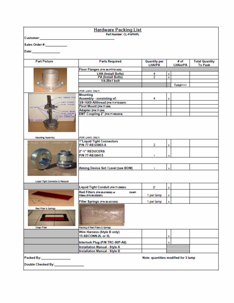
15-FFF2X425
LA-6373
15-201TSA
77-204
77-206
77-207
77-249-117
77-282-402
77-282-601
77-HC83314
77-HS83314SS
77-REG5803-S
77-REG616
77-REG8413
80-015053
80-016045
80-032081
80-019035
80-021077
80-021253
80-021254
Lens heater Class II
77-215
77-281-604
77-821-402
77-RH25.47
PAPI Light Housing Assy. A, I/ll, Tilt Switch
FAA Frangible Floor Fiange
200W 6.6A Quartz G6.35
TILT SWITCH ASSEMBLY
Adapter, all-thread
Pivot, LHA
Filter holder
End stop
Jumper, adjacent
Terminal block, gray. 315"
Catch, stainless steel Strike,
stainless steel Connector, 1"
LT metallic, ins. EMT coupling.
2"
Reducer, 2" to 1"
ZA757/4 lampholder assembly
ZA757/4 lens assembly
CHAPI filter frame assembly(red/wht/grn)
ZA757/4 filter glass, red
Hatch cover
ZA757/4 filter spring
ZA757/4 reflector assembly
Lens heater mount
Terminal block, blue, 236"
Jumper
Resistor. 25W. 47 ohm
15-7X7LHA-X
15-FFF2X425
77-FA9812103
77-FA9812104
77-FA9812101
PAPI Light Housing Assy. B, l/ll, Tilt Switch
FAA Frangible Floor Flange
Printed circuit assembly, master (2 lamp)
Printed circuit assembly, slave (2 lamp)
Printed circuit assembly, master (3 lamp)
77-FA9812102 Printed circuit assembly, slave (3 lamp)
77-HC83314 Catch, stainless steel
77-HS83314SS Strike, stainless steel
77-REG5803-S Connector, 1" LT metallics, ins.
77-REG616 EMT coupling. 2"
77-REG8413 Reducer, 2" to 1"
80-015053 ZA757/4 lampholder assembly
80-016045 ZA757-4 lens assembly
15-MIL-III Programmed Crouzet
Eliana.Rodriguez
Typewritten Text
36

80-019035 ZA757/4 filter glass, red
80-021077 Hatch cover
80-021253 ZA757/4 filter spring
80-021254 ZA757/4 reflector assembly
Lens heater Class II
77-215 Lens heater mount
77-281-604 Terminal block, blue. 236"
77-821-402 Jumper
77-RH25.47 Resistor, 25W. .47 ohm
15-ZA7X7XBPA ZA7X7 2 and 4 box Power Adapter
Components
15-FFF2X425 FAA Frangible Floor Flange
77-282-601 Terminal block, gray, .315"
77-15348U Circuit breaker, 2 poke, 15 Amps, 240 VAC
77-153-0609 Meter, true RMS, 0-10 Amps, 2%
77-213 Enclosure, NEMA 2R, 8"x24"x24"
77-214 Panel, 24"x24"
77-28981 Labbel, Voltage Warning
77-249-116 End stop
77-249-117 End stop
77-280-313 End plate
77-280-402 Jumper, adjacent
77-280-503 Terminal block w/arrester (Modified)
77-AC120L Surge arrester, lightening, 20K amps
77-280-641 Terminal block gray. . 197"
77-281-317 End plate
77-281-604 Terminal block gray. .315"
77-282-317 End plate
77-282-402 Jumper, adjacent
77-282-409 Jumper, alternate
77-W199AX-15 Relay, contactor, 20 amps DPDT, 240 VAC
77-777-310 Tool, for WAGO terminal blocks
77-91115A565 Standoff, SS, 1 1/2" X 1/4" 4-40 hex
77-H050-TB Hub, raintight
77-RTE-P21 Timer, D-O-B, adjustable, 24VAC/DC
77-SR3P-05 Socket, 11 pin
77-TB-201-99 Photo control base
77-TL201-71 Photocontrol 208-277 VAC
Class 1 Only
77-937-100 Transformer, 240/30.3 VAC 60 Hz (ZA757)
77-937-106 Transformer, 240/30.3 VAC 60 Hz (ZA737)
Class 2 Only
77-937-105 Transformer, 240/34 VAC, 60 Hz (ZA757)
77-937-107 Transformer, 240/34 VAC, 60 Hz (ZA737)
77-937-101 Transformer, 220 VAC 50 Hz
15-021041 AIM DEVICE L880 4 BOX
Eliana.Rodriguez
Typewritten Text
37

15-021042 AIM DEVICE L881 2 BOX
77-210 Aiming Device frame
77-98-6 Level, spirit, precision, 6"
77-5211BK Case, 51" X 11"X 5"
77-021041 Aiming Device 4 Box, 5 Pieces
77-021042 Aiming Device 2 Box, 3 Pieces
77-98-6 Level, spirit, precision, 6"
Eliana.Rodriguez
Typewritten Text
38