Instruction Manual equipment/mechanized... · 4. Have fire extinguishing equipment handy for...
64
Smart Voltage Height Control (SVHC-2) System ® Instruction Manual Date: 03Nov11 Part Number: 0558011505 Language: EN
Transcript of Instruction Manual equipment/mechanized... · 4. Have fire extinguishing equipment handy for...

Smart Voltage Height Control (SVHC-2) System
®
Instruction Manual
Date: 03Nov11Part Number: 0558011505Language: EN

2
m3 Smart Voltage Height Control
The equipment described in this manual is potentially hazardous. Use caution when installing, operating, and maintaining this equipment.
The purchaser is responsible for the safe operation and use of all products purchased, including compliance with all applicable standards in the country of use. See standard ESAB terms and conditions of sale for a specific statement of ESAB’s responsibilities and limitations on liability.
This manual is ESAB part number 0558011505.
Information in this document is subject to change without notice. This manual is for the convenience and use of the cutting machine purchaser. It is not a contract or any obligation on the part of ESAB Global Cutting Technology.
ESAB Global Cutting Technology, 2011
Preface
This product was designed to provide years of dependable, accurate, repeatable part cutting, with a high degree of reliability and ease of operation. There are optional features and configurations available which may or may not be included in this manual. In addition, more capabilities and features may be added in the future, which are not covered in this manual. ESAB Global Cutting Technology reserves the right to change or add features and capabilities without notice. Before operating the machine, one should become familiar with this manual in its entirety, with special attention to the SAFETY section.
Revision History:
• 2011 - Original Release
3
m3 Smart Voltage Height Control
Table of Contents
SAFETY
1.0 Safety ............................................................................................................................................................7Introduction .......................................................................................................................................................................................... 7
Safety - English ..................................................................................................................................................................................... 8
Safety - Spanish .................................................................................................................................................................................. 12
Safety - French .................................................................................................................................................................................... 16
DESCRIPTION
2.0 Lift Control Interface (LCI) .........................................................................................................................23Specifications ......................................................................................................................................................................................23
LCI Mounting Dimensions ..............................................................................................................................................................23
CNC Direct Board .............................................................................................................................................................................. 24
2.1 Automatic Height Control (AHC) ...............................................................................................................25Specifications ......................................................................................................................................................................................25
B4 Mounting Dimensions ............................................................................................................................................................... 26
INSTALLATION
3.0 Grounding ...................................................................................................................................................29Introduction ........................................................................................................................................................................................29
Grounding Overview .......................................................................................................................................................................30
Basic Layout ........................................................................................................................................................................................ 31
Elements of a Ground System ....................................................................................................................................................... 32
Plasma Current Return Path .......................................................................................................................................................... 32
Plasma System Safety Ground ...................................................................................................................................................... 33
Rail System Safety Ground .............................................................................................................................................................36
Earth Ground Rod ............................................................................................................................................................................. 37
Ground Rod ......................................................................................................................................................................................... 37

4
m3 Smart Voltage Height Control
Soil Resistivity ..................................................................................................................................................................................... 37
Utility Power Electrical Ground ....................................................................................................................................................38
Multiple Ground Rods ..................................................................................................................................................................... 39
Machine Grounding Schematic....................................................................................................................................................40
3.1 Placement of LCI .........................................................................................................................................42
OPERATION
4.0 Lift Control Interface ..................................................................................................................................45
4.1 Operation ................................................................................................................................................... 46LCI Connectors ...................................................................................................................................................................................46
Setup Descriptions............................................................................................................................................................................ 47
Digital I/O .............................................................................................................................................................................................49
Digital Inputs ......................................................................................................................................................................................49
Digital Outputs...................................................................................................................................................................................49
Display Screens ..................................................................................................................................................................................50
Editing a Parameter on the Display ............................................................................................................................................50
4.2 Modes of Operation: ..................................................................................................................................52Remote Interface ............................................................................................................................................................................... 52
Local Interface - Diagnostics Only ............................................................................................................................................... 53
Operation sequence: ........................................................................................................................................................................ 53
Interface Wiring Descriptions .......................................................................................................................................................54
Interface Wiring .................................................................................................................................................................................54
4.3 Maintenance/Troubleshooting .................................................................................................................58Error Messages on the LCI Display ..............................................................................................................................................58
Process Errors ...................................................................................................................................................................................... 59
Communication Errors ....................................................................................................................................................................60

SAFETY
SAFETY
DESCRIPTIO
NIN
STALLATIO
NO
PERATION

SAFETY
6
This equipment will perform in conformity with the description thereof contained in this manual and accompa-nying labels and/or inserts when installed, operated, maintained and repaired in accordance with the instruc-tions provided. This equipment must be checked periodically. Malfunctioning or poorly maintained equipment should not be used. Parts that are broken, missing, worn, distorted or contaminated should be replaced imme-diately. Should such repair or replacement become necessary, the manufacturer recommends that a telephone or written request for service advice be made to the Authorized Distributor from whom it was purchased.
This equipment or any of its parts should not be altered without the prior written approval of the manufacturer. The user of this equipment shall have the sole responsibility for any malfunction which results from improper use, faulty maintenance, damage, improper repair or alteration by anyone other than the manufacturer or a ser-vice facility designated by the manufacturer.
Be sure this information reaches the operator.
You can get extra copies through your supplier.
These INSTRUCTIONS are for experienced operators. If you are not fully familiar with the principles of operation and safe practices for arc welding and cutting equipment, we urge you to read our booklet, “Precautions and Safe Practices for Arc Welding, Cutting, and Gouging,” Form 52-529. Do NOT permit untrained persons to install, operate, or maintain this equipment. Do NOT attempt to install or operate this equipment until you have read and fully understand these instructions. If you do not fully understand these instructions, contact your supplier for further information. Be sure to read the Safety Precautions be-fore installing or operating this equipment.
USER RESPONSIBILITY
READ AND UNDERSTAND THE INSTRUCTION MANUAL BEFORE INSTALLING OR OPERATING.
PROTECT YOURSELF AND OTHERS!
CAUTION
SAFE
TY

SAFETY
7
Used to call attention to medium risk hazards, which if not avoided, could result in death or serious injury.WARNING
1.0 Safety Introduction
ESAB cutting machines are designed to operate both safely and effectively. Sensible attention to operating procedures, precautions, and safe practices is required to achieve a full measure of usefulness. Whether an individual is involved with operation, servicing, or as an observer, compliance with established precautions is mandatory. Failure to observe precautions could result in equipment damage, serious injury, or death. The following precautions are guidelines when working with cutting machines and associated equipment. More explicit precautions are found within the instruction literature. For specific safety information, obtain and read publications listed in Recommended References.
The following words and symbols are used throughout this manual to indicate different levels of required safety involvement:
Used to call attention to important information not directly related to safety hazards or could potentially cause equipment damage.
Used to call attention to high risk hazards, which if not avoided, will result in death or serious injury.DANGER
Used to call attention to low risk hazards, which if not avoided, could result in minor or moderate injury.CAUTION
SAFETY

SAFETY
8
Safety - English
WARNING: These Safety Precautions are for your protection. They summarize precautionary information from the references listed in Additional Safety
Information section. Before performing any instal-lation or operating procedures, be sure to read and follow the safety precautions listed below as well as all other manuals, material safety data sheets, labels, etc. Failure to observe Safety Precautions can result in injury or death.
PROTECT YOURSELF AND OTHERS -- Some welding, cutting, and gouging processes are noisy and require ear protection. The arc, like the sun, emits
ultraviolet (UV) and other radiation and can injure skin and eyes. Hot metal can cause burns. Training in the proper use of the processes and equipment is essential to prevent accidents. Therefore:
1. Always wear safety glasses with side shields in any work area, even if welding helmets, face shields, and goggles are also required.
2. Use a face shield fitted with the correct filter and cover plates to protect your eyes, face, neck, and ears from sparks and rays of the arc when oper-ating or observing operations. Warn bystanders not to watch the arc and not to expose themselves to the rays of the electric-arc or hot metal.
3. Wear flameproof gauntlet type gloves, heavy long-sleeve shirt, cuffless trousers, high-topped shoes, and a welding helmet or cap for hair protection, to protect against arc rays and hot sparks or hot metal. A flameproof apron may also be desirable as protection against radiated heat and sparks.
4. Hot sparks or metal can lodge in rolled up sleeves, trouser cuffs, or pockets. Sleeves and collars should be kept buttoned, and open pockets eliminated from the front of clothing.
5. Protect other personnel from arc rays and hot sparks with a suitable non-flammable partition or curtains.
6. Use goggles over safety glasses when chipping slag or grinding. Chipped slag may be hot and can fly far. Bystanders should also wear goggles over safety glasses.
FIRES AND EXPLOSIONS -- Heat from flames and arcs can start fires. Hot slag or sparks can also cause fires and explosions. Therefore:
1. Remove all combustible materials well away from the work area or cover the materials with a pro-tective non-flammable covering. Combustible materials include wood, cloth, sawdust, liquid and gas fuels, solvents, paints and coatings, paper, etc.
2. Hot sparks or hot metal can fall through cracks or crevices in floors or wall openings and cause a hidden smoldering fire or fires on the floor below. Make certain that such openings are protected from hot sparks and metal.“
3. Do not weld, cut or perform other hot work until the work piece has been completely cleaned so that there are no substances on the work piece which might produce flammable or toxic vapors. Do not do hot work on closed containers. They may explode.
4. Have fire extinguishing equipment handy for instant use, such as a garden hose, water pail, sand bucket, or portable fire extinguisher. Be sure you are trained in its use.
5. Do not use equipment beyond its ratings. For example, overloaded welding cable can overheat and create a fire hazard.
6. After completing operations, inspect the work area to make certain there are no hot sparks or hot metal which could cause a later fire. Use fire watchers when necessary.
7. For additional information, refer to NFPA Stan-dard 51B, "Fire Prevention in Use of Cutting and Welding Processes", available from the National Fire Protection Association, Battery march Park, Quincy, MA 02269.
ELECTRICAL SHOCK -- Contact with live electrical parts and ground can cause severe injury or death. DO NOT use AC welding current in damp areas, if movement is confined, or if there is danger of falling.
SAFE
TY
SAFETY
9
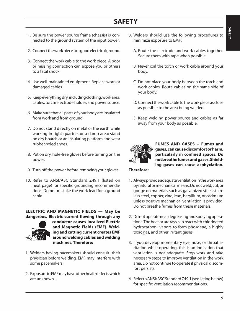
1. Be sure the power source frame (chassis) is con-nected to the ground system of the input power.
2. Connect the work piece to a good electrical ground.
3. Connect the work cable to the work piece. A poor or missing connection can expose you or others to a fatal shock.
4. Use well-maintained equipment. Replace worn or damaged cables.
5. Keep everything dry, including clothing, work area,
cables, torch/electrode holder, and power source.
6. Make sure that all parts of your body are insulated from work and from ground.
7. Do not stand directly on metal or the earth while working in tight quarters or a damp area; stand on dry boards or an insulating platform and wear rubber-soled shoes.
8. Put on dry, hole-free gloves before turning on the power.
9. Turn off the power before removing your gloves.
10. Refer to ANSI/ASC Standard Z49.1 (listed on next page) for specific grounding recommenda-tions. Do not mistake the work lead for a ground cable.
ELECTRIC AND MAGNETIC FIELDS — May be dangerous. Electric current flowing through any
conductor causes localized Electric and Magnetic Fields (EMF). Weld-ing and cutting current creates EMF around welding cables and welding machines. Therefore:
1. Welders having pacemakers should consult their physician before welding. EMF may interfere with some pacemakers.
2. Exposure to EMF may have other health effects which are unknown.
3. Welders should use the following procedures to minimize exposure to EMF:
A. Route the electrode and work cables together. Secure them with tape when possible.
B. Never coil the torch or work cable around your body.
C. Do not place your body between the torch and work cables. Route cables on the same side of your body.
D. Connect the work cable to the work piece as close as possible to the area being welded.
E. Keep welding power source and cables as far away from your body as possible.
FUMES AND GASES -- Fumes and gases, can cause discomfort or harm, particularly in confined spaces. Do not breathe fumes and gases. Shield-ing gases can cause asphyxiation.
Therefore:
1. Always provide adequate ventilation in the work area by natural or mechanical means. Do not weld, cut, or gouge on materials such as galvanized steel, stain-less steel, copper, zinc, lead, beryllium, or cadmium unless positive mechanical ventilation is provided. Do not breathe fumes from these materials.
2. Do not operate near degreasing and spraying opera-tions. The heat or arc rays can react with chlorinated hydrocarbon vapors to form phosgene, a highly toxic gas, and other irritant gases.
3. If you develop momentary eye, nose, or throat ir-ritation while operating, this is an indication that ventilation is not adequate. Stop work and take necessary steps to improve ventilation in the work area. Do not continue to operate if physical discom-fort persists.
4. Refer to ANSI/ASC Standard Z49.1 (see listing below) for specific ventilation recommendations.
SAFETY
SAFETY
10
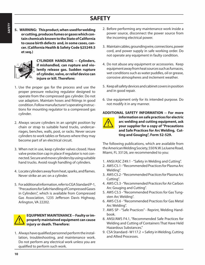
5. WARNING: This product, when used for welding or cutting, produces fumes or gases which con-tain chemicals known to the State of California to cause birth defects and, in some cases, can-cer. (California Health & Safety Code §25249.5 et seq.)
CYLINDER HANDLING -- Cylinders, if mishandled, can rupture and vio-lently release gas. Sudden rupture of cylinder, valve, or relief device can injure or kill. Therefore:
1. Use the proper gas for the process and use the proper pressure reducing regulator designed to operate from the compressed gas cylinder. Do not use adaptors. Maintain hoses and fittings in good condition. Follow manufacturer's operating instruc-tions for mounting regulator to a compressed gas cylinder.
2. Always secure cylinders in an upright position by chain or strap to suitable hand trucks, undercar-riages, benches, walls, post, or racks. Never secure cylinders to work tables or fixtures where they may become part of an electrical circuit.
3. When not in use, keep cylinder valves closed. Have valve protection cap in place if regulator is not con-nected. Secure and move cylinders by using suitable hand trucks. Avoid rough handling of cylinders.
4. Locate cylinders away from heat, sparks, and flames. Never strike an arc on a cylinder.
5. For additional information, refer to CGA Standard P-1, "Precautions for Safe Handling of Compressed Gases in Cylinders", which is available from Compressed Gas Association, 1235 Jefferson Davis Highway, Arlington, VA 22202.
EQUIPMENT MAINTENANCE -- Faulty or im-properly maintained equipment can cause injury or death. Therefore:
1. Always have qualified personnel perform the instal-lation, troubleshooting, and maintenance work. Do not perform any electrical work unless you are qualified to perform such work.
2. Before performing any maintenance work inside a power source, disconnect the power source from the incoming electrical power.
3. Maintain cables, grounding wire, connections, power cord, and power supply in safe working order. Do not operate any equipment in faulty condition.
4. Do not abuse any equipment or accessories. Keep equipment away from heat sources such as furnaces, wet conditions such as water puddles, oil or grease, corrosive atmospheres and inclement weather.
5. Keep all safety devices and cabinet covers in position and in good repair.
6. Use equipment only for its intended purpose. Do not modify it in any manner.
ADDITIONAL SAFETY INFORMATION -- For more information on safe practices for electric arc welding and cutting equipment, ask your supplier for a copy of "Precautions and Safe Practices for Arc Welding, Cut-ting and Gouging", Form 52-529.
The following publications, which are available from the American Welding Society, 550 N.W. LeJuene Road, Miami, FL 33126, are recommended to you:
1. ANSI/ASC Z49.1 - “Safety in Welding and Cutting”.2. AWS C5.1 - “Recommended Practices for Plasma Arc
Welding”.3. AWS C5.2 - “Recommended Practices for Plasma Arc
Cutting”.4. AWS C5.3 - “Recommended Practices for Air Carbon
Arc Gouging and Cutting”.5. AWS C5.5 - “Recommended Practices for Gas Tung-
sten Arc Welding“.6. AWS C5.6 - “Recommended Practices for Gas Metal
Arc Welding”.7. AWS SP - “Safe Practices” - Reprint, Welding Hand-
book.8. ANSI/AWS F4.1, “Recommended Safe Practices for
Welding and Cutting of Containers That Have Held Hazardous Substances.”
9. CSA Standard - W117.2 = Safety in Welding, Cutting and Allied Processes.
SAFE
TY

SAFETY
11
The IP code indicates the enclosure class, i.e. the degree of protection against penetration by solid objects or water. Protection is provided against touch with a finger, penetration of solid objects greater than 12mm and against spraying water up to 60 degrees from vertical. Equipment marked IP23S may be stored, but is not intended to be used outside during precipitation unless sheltered.
Enclosure Class
This product is solely intended for plasma cutting. Any other use may result in personal injury and / or equipment damage.
15°
MaximumTilt Allowed
CAUTIONIf equipment is placed on a surface that slopes more than 15°, toppling over may occur. Personal injury and / or significant damage to equipment is possible.
CAUTIONTo avoid personal injury and/or equipment damage, lift using method and attachment points shown here.
CAUTION
CAUTION
CAUTION
Means immediate hazards which, if not avoided, will result in immediate, serious personal injury or loss of life.
Means potential hazards which could result in personal injury or loss of life.
Means hazards which could result in minor personal injury.
MEANING OF SYMBOLS - As used throughout this manual: Means Attention! Be Alert! Your safety is involved.
WARNING
DANGER
CAUTION
SAFETY

SAFETY
12
Safety - SpanishADVERTENCIA: Estas Precauciones de Seguridad son para su protección. Ellas hacen resumen de información prove-
niente de las referencias listadas en la sección "Información Adicional Sobre La Seguridad". Antes de hacer cualquier instalación o procedimiento de operación , asegúrese de leer y seguir las precaucio-nes de seguridad listadas a continuación así como también todo manual, hoja de datos de seguridad del material, calcomanias, etc. El no observar las Precauciones de Seguridad puede resultar en daño a la persona o muerte.
PROTEJASE USTED Y A LOS DEMAS-- Algunos procesos de soldadura, corte y ranurado son ruidosos y requiren protección para los oídos. El arco, como
el sol , emite rayos ultravioleta (UV) y otras radiaciones que pueden dañar la piel y los ojos. El metal caliente causa quemaduras. EL entrenamiento en el uso propio de los equipos y sus procesos es esencial para prevenir accidentes. Por lo tanto:
1. Utilice gafas de seguridad con protección a los lados siempre que esté en el área de trabajo, aún cuando esté usando careta de soldar, protector para su cara u otro tipo de protección.
2. Use una careta que tenga el filtro correcto y lente para proteger sus ojos, cara, cuello, y oídos de las chispas y rayos del arco cuando se esté operando y observando las operaciones. Alerte a todas las personas cercanas de no mirar el arco y no exponerse a los rayos del arco eléctrico o el metal fundido.
3. Use guantes de cuero a prueba de fuego, camisa pesada de mangas largas, pantalón de ruedo liso, zapato alto al tobillo, y careta de soldar con capucha para el pelo, para proteger el cuerpo de los rayos y chispas calientes provenientes del metal fundido. En ocaciones un delantal a prueba de fuego es necesario para protegerse del calor radiado y las chispas.
4. Chispas y partículas de metal caliente puede alojarse en las mangas enrolladas de la camisa , el ruedo del pantalón o los bolsillos. Mangas y cuellos deberán mantenerse abotonados, bolsillos al frente de la camisa deberán ser cerrados o eliminados.
5. Proteja a otras personas de los rayos del arco y chispas calientes con una cortina adecuada no-flamable como división.
6. Use careta protectora además de sus gafas de seguridad cuando esté removiendo escoria o puliendo.
La escoria puede estar caliente y desprenderse con velocidad. Personas cercanas deberán usar gafas de seguridad y careta protectora.
FUEGO Y EXPLOSIONES -- El calor de las flamas y el arco pueden ocacionar fuegos. Escoria caliente y las chispas pueden causar fuegos y explosiones. Por lo tanto:
1. Remueva todo material combustible lejos del área de trabajo o cubra los materiales con una cobija a prueba de fuego. Materiales combustibles incluyen madera, ropa, líquidos y gases flamables, solventes, pinturas, papel, etc.
2. Chispas y partículas de metal pueden introducirse en las grietas y agujeros de pisos y paredes causando fuegos escondidos en otros niveles o espacios. Asegúrese de que toda grieta y agujero esté cubierto para proteger lugares adyacentes contra fuegos.
3. No corte, suelde o haga cualquier otro trabajo relacionado hasta que la pieza de trabajo esté totalmente limpia y libre de substancias que puedan producir gases inflam-ables o vapores tóxicos. No trabaje dentro o fuera de contenedores o tanques cerrados. Estos pueden explotar si contienen vapores inflamables.
4. Tenga siempre a la mano equipo extintor de fuego para uso instantáneo, como por ejemplo una manguera con agua, cubeta con agua, cubeta con arena, o extintor portátil. Asegúrese que usted esta entrenado para su uso.
5. No use el equipo fuera de su rango de operación. Por ejemplo, el calor causado por cable sobrecarga en los cables de soldar pueden ocasionar un fuego.
6. Después de termirar la operación del equipo, inspeccione el área de trabajo para cerciorarse de que las chispas o metal caliente ocasionen un fuego más tarde. Tenga personal asignado para vigilar si es necesario.
7. Para información adicional , haga referencia a la pub-licación NFPA Standard 51B, "Fire Prevention in Use of Cutting and Welding Processes", disponible a través de la National Fire Protection Association, Batterymarch Park, Quincy, MA 02269.
CHOQUE ELECTRICO -- El contacto con las partes eléc-tricas energizadas y tierra puede causar daño severo
o muerte. NO use soldadura de corriente alterna (AC) en áreas húmedas, de mov-imiento confinado en lugares estrechos o si hay posibilidad de caer al suelo.
SAFE
TY
SAFETY
13
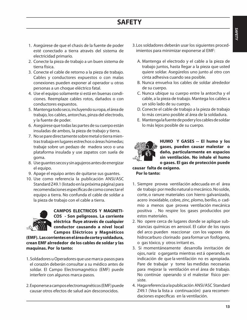
1. Asegúrese de que el chasis de la fuente de poder esté conectado a tierra através del sistema de electricidad primario.
2. Conecte la pieza de trabajo a un buen sistema de tierra física.
3. Conecte el cable de retorno a la pieza de trabajo. Cables y conductores expuestos o con malas conexiones pueden exponer al operador u otras personas a un choque eléctrico fatal.
4. Use el equipo solamente si está en buenas condi-ciones. Reemplaze cables rotos, dañados o con conductores expuestos.
5. Mantenga todo seco, incluyendo su ropa, el área de trabajo, los cables, antorchas, pinza del electrodo, y la fuente de poder.
6. Asegúrese que todas las partes de su cuerpo están insuladas de ambos, la pieza de trabajo y tierra.
7. No se pare directamente sobre metal o tierra mien-tras trabaja en lugares estrechos o áreas húmedas; trabaje sobre un pedazo de madera seco o una plataforma insulada y use zapatos con suela de goma.
8. Use guantes secos y sin agujeros antes de energizar el equipo.
9. Apage el equipo antes de quitarse sus guantes. 10. Use como referencia la publicación ANSI/ASC
Standard Z49.1 (listado en la próxima página) para recomendaciones específicas de como conectar el equipo a tierra. No confunda el cable de soldar a la pieza de trabajo con el cable a tierra.
CAMPOS ELECTRICOS Y MAGNETI-COS - Son peligrosos. La corriente eléctrica fluye através de cualquier conductor causando a nivel local Campos Eléctricos y Magnéticos
(EMF). Las corrientes en el área de corte y soldadura, crean EMF alrrededor de los cables de soldar y las maquinas. Por lo tanto: 1. Soldadores u Operadores que use marca-pasos para
el corazón deberán consultar a su médico antes de soldar. El Campo Electromagnético (EMF) puede interferir con algunos marca-pasos.
2. Exponerse a campos electromagnéticos (EMF) puede causar otros efectos de salud aún desconocidos.
3. Los soldadores deberán usar los siguientes proced-imientos para minimizar exponerse al EMF:
A. Mantenga el electrodo y el cable a la pieza de trabajo juntos, hasta llegar a la pieza que usted quiere soldar. Asegúrelos uno junto al otro con cinta adhesiva cuando sea posible.
B. Nunca envuelva los cables de soldar alrededor de su cuerpo.
C. Nunca ubique su cuerpo entre la antorcha y el cable, a la pieza de trabajo. Mantega los cables a un sólo lado de su cuerpo.
D. Conecte el cable de trabajo a la pieza de trabajo lo más cercano posible al área de la soldadura.
E. Mantenga la fuente de poder y los cables de soldar lo más lejos posible de su cuerpo.
HUMO Y GASES -- El humo y los gases, pueden causar malestar o daño, particularmente en espacios sin ventilación. No inhale el humo o gases. El gas de protección puede
causar falta de oxígeno. Por lo tanto:
1. Siempre provea ventilación adecuada en el área de trabajo por medio natural o mecánico. No solde, corte, o ranure materiales con hierro galvanizado, acero inoxidable, cobre, zinc, plomo, berílio, o cad-mio a menos que provea ventilación mecánica positiva . No respire los gases producidos por estos materiales.
2. No opere cerca de lugares donde se aplique sub-stancias químicas en aerosol. El calor de los rayos del arco pueden reaccionar con los vapores de hidrocarburo clorinado para formar un fosfógeno, o gas tóxico, y otros irritant es.
3. Si momentáneamente desarrolla inrritación de ojos, nariz o garganta mientras est á operando, es indicación de que la ventilación no es apropiada. Pare de trabajar y tome las medidas necesarias para mejorar la ventilación en el área de trabajo. No continúe operando si el malestar físico per-siste.
4. Haga referencia a la publicación ANSI/ASC Standard Z49.1 (Vea la lista a continuación) para recomen-daciones específicas en la ventilación.
SAFETY
SAFETY
14
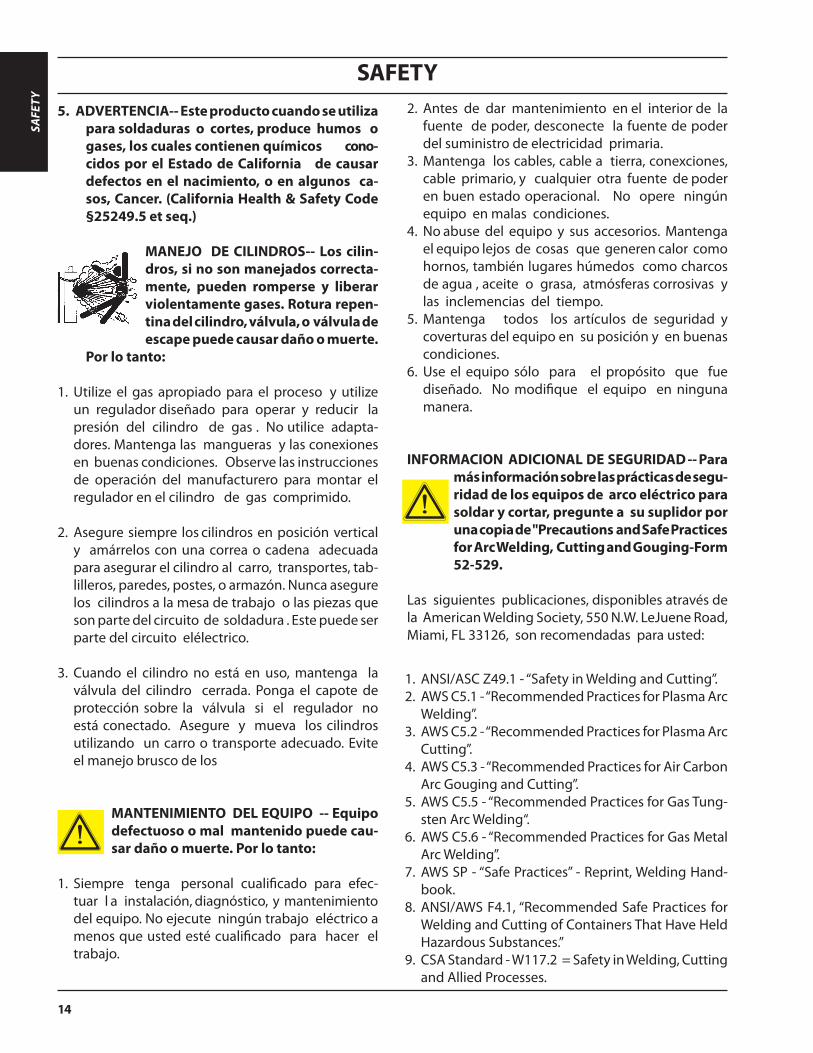
5. ADVERTENCIA-- Este producto cuando se utiliza para soldaduras o cortes, produce humos o gases, los cuales contienen químicos cono-cidos por el Estado de California de causar defectos en el nacimiento, o en algunos ca-sos, Cancer. (California Health & Safety Code §25249.5 et seq.)
MANEJO DE CILINDROS-- Los cilin-dros, si no son manejados correcta-mente, pueden romperse y liberar violentamente gases. Rotura repen-tina del cilindro, válvula, o válvula de escape puede causar daño o muerte.
Por lo tanto:
1. Utilize el gas apropiado para el proceso y utilize un regulador diseñado para operar y reducir la presión del cilindro de gas . No utilice adapta-dores. Mantenga las mangueras y las conexiones en buenas condiciones. Observe las instrucciones de operación del manufacturero para montar el regulador en el cilindro de gas comprimido.
2. Asegure siempre los cilindros en posición vertical y amárrelos con una correa o cadena adecuada para asegurar el cilindro al carro, transportes, tab-lilleros, paredes, postes, o armazón. Nunca asegure los cilindros a la mesa de trabajo o las piezas que son parte del circuito de soldadura . Este puede ser parte del circuito elélectrico.
3. Cuando el cilindro no está en uso, mantenga la válvula del cilindro cerrada. Ponga el capote de protección sobre la válvula si el regulador no está conectado. Asegure y mueva los cilindros utilizando un carro o transporte adecuado. Evite el manejo brusco de los
MANTENIMIENTO DEL EQUIPO -- Equipo defectuoso o mal mantenido puede cau-sar daño o muerte. Por lo tanto:
1. Siempre tenga personal cualificado para efec-tuar l a instalación, diagnóstico, y mantenimiento del equipo. No ejecute ningún trabajo eléctrico a menos que usted esté cualificado para hacer el trabajo.
2. Antes de dar mantenimiento en el interior de la fuente de poder, desconecte la fuente de poder del suministro de electricidad primaria.
3. Mantenga los cables, cable a tierra, conexciones, cable primario, y cualquier otra fuente de poder en buen estado operacional. No opere ningún equipo en malas condiciones.
4. No abuse del equipo y sus accesorios. Mantenga el equipo lejos de cosas que generen calor como hornos, también lugares húmedos como charcos de agua , aceite o grasa, atmósferas corrosivas y las inclemencias del tiempo.
5. Mantenga todos los artículos de seguridad y coverturas del equipo en su posición y en buenas condiciones.
6. Use el equipo sólo para el propósito que fue diseñado. No modifique el equipo en ninguna manera.
INFORMACION ADICIONAL DE SEGURIDAD -- Para más información sobre las prácticas de segu-ridad de los equipos de arco eléctrico para soldar y cortar, pregunte a su suplidor por una copia de "Precautions and Safe Practices for Arc Welding, Cutting and Gouging-Form 52-529.
Las siguientes publicaciones, disponibles através de la American Welding Society, 550 N.W. LeJuene Road, Miami, FL 33126, son recomendadas para usted:
1. ANSI/ASC Z49.1 - “Safety in Welding and Cutting”.2. AWS C5.1 - “Recommended Practices for Plasma Arc
Welding”.3. AWS C5.2 - “Recommended Practices for Plasma Arc
Cutting”.4. AWS C5.3 - “Recommended Practices for Air Carbon
Arc Gouging and Cutting”.5. AWS C5.5 - “Recommended Practices for Gas Tung-
sten Arc Welding“.6. AWS C5.6 - “Recommended Practices for Gas Metal
Arc Welding”.7. AWS SP - “Safe Practices” - Reprint, Welding Hand-
book.8. ANSI/AWS F4.1, “Recommended Safe Practices for
Welding and Cutting of Containers That Have Held Hazardous Substances.”
9. CSA Standard - W117.2 = Safety in Welding, Cutting and Allied Processes.
SAFE
TY

SAFETY
15
SIGNIFICADO DE LOS SIMBOLOS -- Según usted avanza en la lectura de este folleto: Los Símbolos Significan ¡Atención! ¡Esté Alerta! Se trata de su seguridad.
Significa el riesgo de un peligro potencial que puede resultar en serio daño personal o la muerte.
Significa el posible riesgo que puede resultar en menores daños a la persona.
El código IP indica la clase de envolvente, es decir, el grado de protección contra la penetración de objetos sólidos o agua. Se provee protección contra el toque con un dedo, penetración de objetos sólidos de un tamaño superior a 12 mm y contra rocío de agua de hasta 60 grados de la vertical. El equipo marcado IP23S se puede almacenar, pero no se debe usar en el exterior durante periodos de precipitaciones a menos que esté protegido.
Clase de envolvente
Este producto sólo se debe usar para corte por plasma Cualquier otro uso puede causar lesiones físicas y/o daños en los equipos.
15°
Inclinación máxima permitidaSi el equipo se coloca sobre una superficie con una
inclinación superior a 15°, se puede producir un vol-camiento. Es posible que se produzcan lesiones físi-cas y/o daños importantes en los equipos.
Para evitar lesiones físicas y/o daños en los equipos, levante mediante el método y los puntos de sujeción que se indican en esta ilustración.
Significa riesgo inmediato que, de no ser evadido, puede resultar inmediata-mente en serio daño personal o la muerte.
CUIDADO
pElIGRO
ADVERTENCIA
ADVERTENCIA
ADVERTENCIA
ADVERTENCIA
SAFETY
SAFETY
16
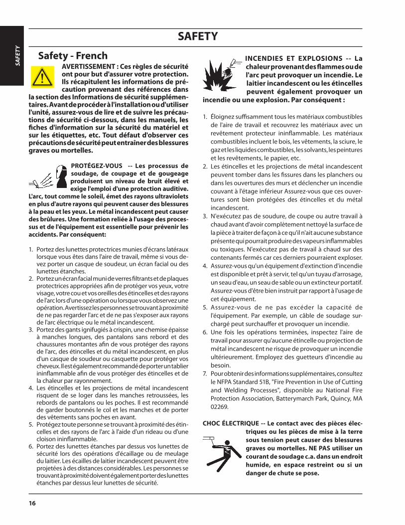
Safety - French INCENDIES ET EXPLOSIONS -- La chaleur provenant des flammes ou de l'arc peut provoquer un incendie. Le laitier incandescent ou les étincelles peuvent également provoquer un
incendie ou une explosion. Par conséquent :
1. Éloignez suffisamment tous les matériaux combustibles de l'aire de travail et recouvrez les matériaux avec un revêtement protecteur ininflammable. Les matériaux combustibles incluent le bois, les vêtements, la sciure, le gaz et les liquides combustibles, les solvants, les peintures et les revêtements, le papier, etc.
2. Les étincelles et les projections de métal incandescent peuvent tomber dans les fissures dans les planchers ou dans les ouvertures des murs et déclencher un incendie couvant à l'étage inférieur Assurez-vous que ces ouver-tures sont bien protégées des étincelles et du métal incandescent.
3. N'exécutez pas de soudure, de coupe ou autre travail à chaud avant d'avoir complètement nettoyé la surface de la pièce à traiter de façon à ce qu'il n'ait aucune substance présente qui pourrait produire des vapeurs inflammables ou toxiques. N'exécutez pas de travail à chaud sur des contenants fermés car ces derniers pourraient exploser.
4. Assurez-vous qu'un équipement d'extinction d'incendie est disponible et prêt à servir, tel qu'un tuyau d'arrosage, un seau d'eau, un seau de sable ou un extincteur portatif. Assurez-vous d'être bien instruit par rapport à l'usage de cet équipement.
5. Assurez-vous de ne pas excéder la capacité de l'équipement. Par exemple, un câble de soudage sur-chargé peut surchauffer et provoquer un incendie.
6. Une fois les opérations terminées, inspectez l'aire de travail pour assurer qu'aucune étincelle ou projection de métal incandescent ne risque de provoquer un incendie ultérieurement. Employez des guetteurs d'incendie au besoin.
7. Pour obtenir des informations supplémentaires, consultez le NFPA Standard 51B, "Fire Prevention in Use of Cutting and Welding Processes", disponible au National Fire Protection Association, Batterymarch Park, Quincy, MA 02269.
CHOC ÉLECTRIQUE -- Le contact avec des pièces élec-triques ou les pièces de mise à la terre sous tension peut causer des blessures graves ou mortelles. NE PAS utiliser un courant de soudage c.a. dans un endroit humide, en espace restreint ou si un danger de chute se pose.
AVERTISSEMENT : Ces règles de sécurité ont pour but d'assurer votre protection. Ils récapitulent les informations de pré-caution provenant des références dans
la section des Informations de sécurité supplémen-taires. Avant de procéder à l'installation ou d'utiliser l'unité, assurez-vous de lire et de suivre les précau-tions de sécurité ci-dessous, dans les manuels, les fiches d'information sur la sécurité du matériel et sur les étiquettes, etc. Tout défaut d'observer ces précautions de sécurité peut entraîner des blessures graves ou mortelles.
PROTÉGEZ-VOUS -- Les processus de soudage, de coupage et de gougeage produisent un niveau de bruit élevé et exige l'emploi d'une protection auditive.
L'arc, tout comme le soleil, émet des rayons ultraviolets en plus d'autre rayons qui peuvent causer des blessures à la peau et les yeux. Le métal incandescent peut causer des brûlures. Une formation reliée à l'usage des proces-sus et de l'équipement est essentielle pour prévenir les accidents. Par conséquent: 1. Portez des lunettes protectrices munies d'écrans latéraux
lorsque vous êtes dans l'aire de travail, même si vous de-vez porter un casque de soudeur, un écran facial ou des lunettes étanches.
2. Portez un écran facial muni de verres filtrants et de plaques protectrices appropriées afin de protéger vos yeux, votre visage, votre cou et vos oreilles des étincelles et des rayons de l'arc lors d'une opération ou lorsque vous observez une opération. Avertissez les personnes se trouvant à proximité de ne pas regarder l'arc et de ne pas s'exposer aux rayons de l'arc électrique ou le métal incandescent.
3. Portez des gants ignifugiés à crispin, une chemise épaisse à manches longues, des pantalons sans rebord et des chaussures montantes afin de vous protéger des rayons de l'arc, des étincelles et du métal incandescent, en plus d'un casque de soudeur ou casquette pour protéger vos cheveux. Il est également recommandé de porter un tablier ininflammable afin de vous protéger des étincelles et de la chaleur par rayonnement.
4. Les étincelles et les projections de métal incandescent risquent de se loger dans les manches retroussées, les rebords de pantalons ou les poches. Il est recommandé de garder boutonnés le col et les manches et de porter des vêtements sans poches en avant.
5. Protégez toute personne se trouvant à proximité des étin-celles et des rayons de l'arc à l'aide d'un rideau ou d'une cloison ininflammable.
6. Portez des lunettes étanches par dessus vos lunettes de sécurité lors des opérations d'écaillage ou de meulage du laitier. Les écailles de laitier incandescent peuvent être projetées à des distances considérables. Les personnes se trouvant à proximité doivent également porter des lunettes étanches par dessus leur lunettes de sécurité.
SAFE
TY

SAFETY
17
3. Les soudeurs doivent suivre les procédures suivantes pour minimiser l'exposition aux champs électriques et magnétiques :
A. Acheminez l'électrode et les câbles de masse ensemble. Fixez-les à l'aide d'une bande adhésive lorsque possible.
B. Ne jamais enrouler la torche ou le câble de masse autour de votre corps.
C. Ne jamais vous placer entre la torche et les câbles de masse. Acheminez tous les câbles sur le même côté de votre corps.
D. Branchez le câble de masse à la pièce à traiter le plus près possible de la section à souder.
E. Veillez à garder la source d'alimentation pour le soudage et les câbles à une distance appropriée de votre corps.
LES VAPEURS ET LES GAZ -- peuvent causer un malaise ou des dommages corporels, plus particulièrement dans les espaces restreints. Ne re-spirez pas les vapeurs et les gaz. Le gaz de protection risque de causer l'asphyxie. Par conséquent :
1. Assurez en permanence une ventilation adéquate dans l'aire de travail en maintenant une ventila-tion naturelle ou à l'aide de moyens mécanique. N'effectuez jamais de travaux de soudage, de coup-age ou de gougeage sur des matériaux tels que l'acier galvanisé, l'acier inoxydable, le cuivre, le zinc, le plomb, le berylliym ou le cadmium en l'absence de moyens mécaniques de ventilation efficaces. Ne respirez pas les vapeurs de ces matériaux.
2. N'effectuez jamais de travaux à proximité d'une opération de dégraissage ou de pulvérisation. Lorsque la chaleur
ou le rayonnement de l'arc entre en contact avec les vapeurs d'hydrocarbure chloré, ceci peut déclencher la formation de phosgène ou d'autres gaz irritants, tous extrêmement toxiques.
3. Une irritation momentanée des yeux, du nez ou de la gorge au cours d'une opération indique que la ven-tilation n'est pas adéquate. Cessez votre travail afin de prendre les mesures nécessaires pour améliorer la ventilation dans l'aire de travail. Ne poursuivez pas l'opération si le malaise persiste.
4. Consultez ANSI/ASC Standard Z49.1 (à la page suivante) pour des recommandations spécifiques concernant la ventilation.
1. Assurez-vous que le châssis de la source d'alimentation est branché au système de mise à la terre de l'alimentation d'entrée.
2. Branchez la pièce à traiter à une bonne mise de terre électrique.
3. Branchez le câble de masse à la pièce à traiter et assurez une bonne connexion afin d'éviter le risque de choc électrique mortel.
4. Utilisez toujours un équipement correctement entretenu. Remplacez les câbles usés ou endom-magés.
5. Veillez à garder votre environnement sec, incluant les vêtements, l'aire de travail, les câbles, le porte-électrode/torche et la source d'alimentation.
6. Assurez-vous que tout votre corps est bien isolé de la pièce à traiter et des pièces de la mise à la terre.
7. Si vous devez effectuer votre travail dans un espace restreint ou humide, ne tenez vous pas directe-ment sur le métal ou sur la terre; tenez-vous sur des planches sèches ou une plate-forme isolée et portez des chaussures à semelles de caoutchouc.
8. Avant de mettre l'équipement sous tension, isolez vos mains avec des gants secs et sans trous.
9. Mettez l'équipement hors tension avant d'enlever vos gants.
10. Consultez ANSI/ASC Standard Z49.1 (listé à la page suivante) pour des recommandations spécifiques concernant les procédures de mise à la terre. Ne pas confondre le câble de masse avec le câble de mise à la terre.
CHAMPS ÉLECTRIQUES ET MAGNÉTIQUES — com-portent un risque de danger. Le courant électrique qui passe dans n'importe quel conducteur produit des champs électriques et magné-tiques localisés. Le soudage et le
courant de coupage créent des champs électriques et magnétiques autour des câbles de soudage et l'équipement. Par conséquent :
1. Un soudeur ayant un stimulateur cardiaque doit consulter son médecin avant d'entreprendre une opération de soudage. Les champs électriques et magnétiques peuvent causer des ennuis pour cer-tains stimulateurs cardiaques.
2. L'exposition à des champs électriques et magné-tiques peut avoir des effets néfastes inconnus pour la santé.
SAFETY

SAFETY
18
1. Efforcez-vous de toujours confier les tâches d'installation, de dépannage et d'entretien à un personnel qualifié. N'effectuez aucune réparation électrique à moins d'être qualifié à cet effet.
2. Avant de procéder à une tâche d'entretien à l'intérieur de la source d'alimentation, débranchez l'alimentation électrique.
3. Maintenez les câbles, les fils de mise à la terre, les branchements, le cordon d'alimentation et la source d'alimentation en bon état. N'utilisez jamais un équipe-ment s'il présente une défectuosité quelconque.
4. N'utilisez pas l'équipement de façon abusive. Gardez l'équipement à l'écart de toute source de chaleur, notamment des fours, de l'humidité, des flaques d'eau, de l'huile ou de la graisse, des atmosphères corrosives et des intempéries.
5. Laissez en place tous les dispositifs de sécurité et tous les panneaux de la console et maintenez-les en bon état.
6. Utilisez l'équipement conformément à son usage prévu et n'effectuez aucune modification.
INFORMATIONS SUPPLÉMENTAIRES RELATIVES À LA SÉCURITÉ -- Pour obtenir de l'information supplémentaire sur les règles de sécurité à observer pour l'équipement de soudage à
l'arc électrique et le coupage, demandez un exem-plaire du livret "Precautions and Safe Practices for Arc Welding, Cutting and Gouging", Form 52-529.
Les publications suivantes sont également recomman-dées et mises à votre disposition par l'American Weld-ing Society, 550 N.W. LeJuene Road, Miami, FL 33126 :
5. AVERTISSEMENT : Ce produit, lorsqu'il est utilisé dans une opération de soudage ou de coupage, dégage des vapeurs ou des gaz contenant des chimiques considéres par l'état de la Californie comme étant une cause des malformations congénitales et dans certains cas, du cancer. (California Health & Safety Code §25249.5 et seq.)
MANIPULATION DES CYLINDRES -- La manipulation d'un cylindre, sans observer les précautions nécessaires, peut produire des fissures et un échappement dangereux des gaz.
Une brisure soudaine du cylindre, de la soupape ou du dispositif de surpression peut causer des blessures graves ou mortelles. Par conséquent :
1. Utilisez toujours le gaz prévu pour une opération et le détendeur approprié conçu pour utilisation sur les cyl-indres de gaz comprimé. N'utilisez jamais d'adaptateur. Maintenez en bon état les tuyaux et les raccords. Observez les instructions d'opération du fabricant pour assembler le détendeur sur un cylindre de gaz comprimé.
2. Fixez les cylindres dans une position verticale, à l'aide d'une chaîne ou une sangle, sur un chariot manuel, un châssis de roulement, un banc, un mur, une colonne ou un support convenable. Ne fixez jamais un cylindre à un poste de travail ou toute autre dispositif faisant partie d'un circuit électrique.
3. Lorsque les cylindres ne servent pas, gardez les soupapes fermées. Si le détendeur n'est pas branché, assurez-vous que le bouchon de protection de la soupape est bien en place. Fixez et déplacez les cylindres à l'aide d'un chariot manuel approprié. Toujours manipuler les cylindres avec soin.
4. Placez les cylindres à une distance appropriée de toute source de chaleur, des étincelles et des flammes. Ne jamais amorcer l'arc sur un cylindre.
5. Pour de l'information supplémentaire, consultez CGA Standard P-1, "Precautions for Safe Handling of Com-pressed Gases in Cylinders", mis à votre disposition par le Compressed Gas Association, 1235 Jefferson Davis Highway, Arlington, VA 22202.
ENTRETIEN DE L'ÉQUIPEMENT -- Un équipe-ment entretenu de façon défectueuse ou inadéquate peut causer des blessures graves ou mortelles. Par conséquent :
1. ANSI/ASC Z49.1 - “Safety in Welding and Cutting”.2. AWS C5.1 - “Recommended Practices for Plasma Arc
Welding”.3. AWS C5.2 - “Recommended Practices for Plasma Arc
Cutting”.4. AWS C5.3 - “Recommended Practices for Air Carbon
Arc Gouging and Cutting”.5. AWS C5.5 - “Recommended Practices for Gas Tung-
sten Arc Welding“.6. AWS C5.6 - “Recommended Practices for Gas Metal
Arc Welding”.7. AWS SP - “Safe Practices” - Reprint, Welding Hand-
book.8. ANSI/AWS F4.1, “Recommended Safe Practices for
Welding and Cutting of Containers That Have Held Hazardous Substances.”
9. CSA Standard - W117.2 = Safety in Welding, Cutting and Allied Processes.
SAFE
TY

SAFETY
19
Signifie un danger immédiat. La situation peut entraîner des blessures graves ou mortelles.
Signifie un danger potentiel qui peut entraîner des blessures graves ou mortelles.
Signifie un danger qui peut entraîner des blessures corporelles mineures.
L’indice de protection (codification IP) indique la classe de protection de l’enveloppe, c’est-à-dire, le degré de protection contre les corps solides étrangers ou l’eau. L’enveloppe protège contre le toucher, la pénétration d’objets solides dont le diamètre dépasse 12 mm et contre l’eau pulvérisée à un angle de jusqu’à 60 degrés de la verticale. Les équipements portant la marque IP23S peuvent être entreposés à l’extérieur, mais ne sont pas conçus pour être utilisés à l’extérieur pendant une précipitation à moins d’être à l’abri.
Classe de protection de l’enveloppe
Ce produit a été conçu pour la découpe au plasma seulement. Toute autre utilisation pourrait causer des blessures et/ou endommager l’appareil.
15°
Angle d’inclinaison
maximalL’équipement pourrait basculer s’il est placé sur une surface dont la pente dépasse 15°. Vous pourriez vous blesser ou endommager l’équipement de façon importante.
Soulevez à l’aide de la méthode et des points d’attache illustrés afin d’éviter de vous blesser ou d’endommager l’équipement.
ATTENTION
DANGER
AVERTISSEMENT
SIGNIFICATION DES SYMBOLESCe symbole, utilisé partout dans ce manuel, signifie "Attention" ! Soyez vigilant ! Votre sécurité est en jeu.
AVERTISSEMENT
AVERTISSEMENT
AVERTISSEMENT
SAFETY

SAFETY
20
SAFE
TY

DESCRIPTION
SAFETY
DESCRIPTIO
N
INSTA
LLATION
OPERATIO
N

DESCRIPTION
22
ABBREVIATIONS:AHC - Automatic Height Control
LCI - Lift Control Interface
Below are some abbreviations used throughout this manual.
DES
CRIP
TIO
N

DESCRIPTION
23
The Lift Control Interface (LCI) provides the plasma process control including current, gas and torch height (if applicable). It also serves as the interface between the customer CNC and the ESAB SVHC-2 System. At the same time, it functions as a hub for CAN communication.
2.0 Lift Control Interface (LCI)
SpecificationsDimensions: 7.50” (190.5 mm) high x 10.125” (257.2 mm) wide x 6.50” (165.1 mm) deepWeight: 8.5 lbs. (3.9 kg)Operating Temperature 5-40°C (41-104°F)
Max Humidity 95% non-condensing
Enclosure Degree of Protection IP54
Input Power Reduction 230 VAC, 5 Amps
LCI Mounting Dimensions
11.50”(292.1 mm) 0.28”
(7.1 mm)
3.00”(76.2 mm)
p/n 0558009610
DESCRIPTIO
N

DESCRIPTION
24
CNC Direct Board
Port Function Port FunctionX1 CNC Control, DB37
XS2 Switches: Local/Remote, Station Select and Screen SelectX2 RS232
X3 CAN1 and 24VDC input XP1 Programming port 1
X4 CAN2 XP2 Programming port 2
X6 Spare I/O S2, S3 ID switches, by default S2=1, S3=4
X7 Reserved V12 IC, Main processor
X8 Aux Control, DB25 V13 EEPROM, Save data for system configuration, error history, etc.
X9 ASIOB1 Communication V41 IC for ASIOB1
XS1 Switches: Plasma Start, Gas Test J1
DIP switches: 1- 120R for CAN1, 2- 120R for CAN2, 3- VCC to ASIOB1, 4- GND to ASIOB1Default: 1 - ON, 2 - ON, 3 - OFF, 4 - OFF
The CNC Direct board is the control and interface board inside the LCI. It provides the process control, interface to customer CNC, system setup, panel interface, etc. Below is a skeleton of this CNC board. It shows the major components and the major connectors on the board. The table below gives the functions of these connections.
p/n 0558011504
DES
CRIP
TIO
N

DESCRIPTION
25
2.1 Automatic Height Control (AHC)
The B4 lift assembly provides vertical motion for the PT-36 plasma torch, using a typi-cal motor, screw, and slide configuration. The motor turns an enclosed spindle screw, which in turn raises/lowers the lifting plate along linear rails. Directional commands given from the plasma controller determine the direction of the travel. Fixed limit switches are included to prevent upper and lower lift’s over travel.
The lift assembly also contains components necessary to control height over work surfaces; initial, piercing, and cutting heights are encoder controlled during the plas-ma cycle. During part production, height is automatically controlled by taking volt-age measurements between the torch electrode and work surface.
The B4 lifts utilize an Omni Soft Touch® assembly to protect the system during sta-tion crashes. Proximity switches monitor torch position in the torch holder. If the torch is jarred in any direction, the process will stop and an error report will be sent to the controller.
SpecificationsDimensions:
6.0” (152.4 mm) wide x 8.5” (215.9 mm) deep x 31.5” (800.1 mm) highLift Speed: 315 IPM [8.0m per minute]Vertical Travel: 8.00” [200.0 mm]Approximate Weight including torch holder: 85 lbs. [38.5 kg]Torch Barrel Size: 85.7 mm
Component TolerancesIHS Accuracy: ± 0.5 mmEncoder Accuracy: ± 0.25 mmVoltage Accuracy: ± 1 volt
p/n 0560947166
DESCRIPTIO
N

DESCRIPTION
26
B4 lift hole patterns are provided below to aid end users in mounting the plasma station. An optional plasma bracket/nut plate is available. For more specific details, please refer to the B4 Lift manual.
Recommended Monting Bracket/Nut Plate
(6) M8 x 1.25 x 40 Socket Head Cap Screws
5.00”[127.0mm]
4.13” [104.9mm]
0.49” [12.4mm]
3.64” [92.4mm]
4.47”[113.5mm]
x6 M8x1.25 - 6HTHRU HOLES
0.53”[13.5mm]
2.50”[63.5mm]
B4 Mounting Dimensions
DES
CRIP
TIO
N

INSTALLATION
SAFETY
DESCRIPTIO
N
INSTA
LLATION
OPERATIO
N

INSTALLATION
28
INST
ALL
ATIO
N

INSTALLATION
29
3.0 Grounding
Introduction
Machine grounding is an important part of the installation process, which can be greatly simplified if prepared in advance. The most difficult part of the grounding process is designing and installing a low impedance Earth ground rod. However, the better the Earth ground rod, the less chance there is of having electromagnetic interference problems after the installation is complete.
Most national electric codes address grounding for the purpose of fire prevention and short circuit protection; they do not address equipment protection and electromagnetic interference noise reduction. Therefore, this manual presents more stringent requirements for machine grounding.
WARNINGElECTRIC ShOCk hAzARD.
Improper grounding can cause severe injury or death.
Improper grounding can damage machine electrical components.
Machine must be properly grounded before putting it into service.
The cutting table must be connected to machine earth grounding rod.
INSTA
LLATION

INSTALLATION
30
Grounding Overview
There are three parts to a ground system;
• Component or "chassis" ground
• Earth ground
• Protective Earth ground
Component grounding connects all pieces to a single component, like the machine chassis, which is then connected to a common point known as the star point. This provides a path for electromagnetic interference (EMI) from the enclosure to ground.
An earth ground provides a electromagnetic interference (EMI) to return to its source.
A protective earth (PE) ground provides a safe path for fault current. Without a properly grounded system, an unintended path through people or sensitive equipment may be found, resulting in serious injury, death, and/or premature equipment failure.
This section focuses on machines with a plasma cutting system. Machines with plasma cutting capability are particularly prone to electromagnetic interference problems and often utilize dangerous voltages and currents. All machines must have electrical components grounded and attached to an earth ground, regardless of process type (shape cutting, marking, or other material preparation).
A common symbol used to identify an earth ground on drawings.
A common symbol used to identify a chassis ground on drawings.
A common symbol used to identify a protective earth (PE) ground.
INST
ALL
ATIO
N
INSTALLATION
31
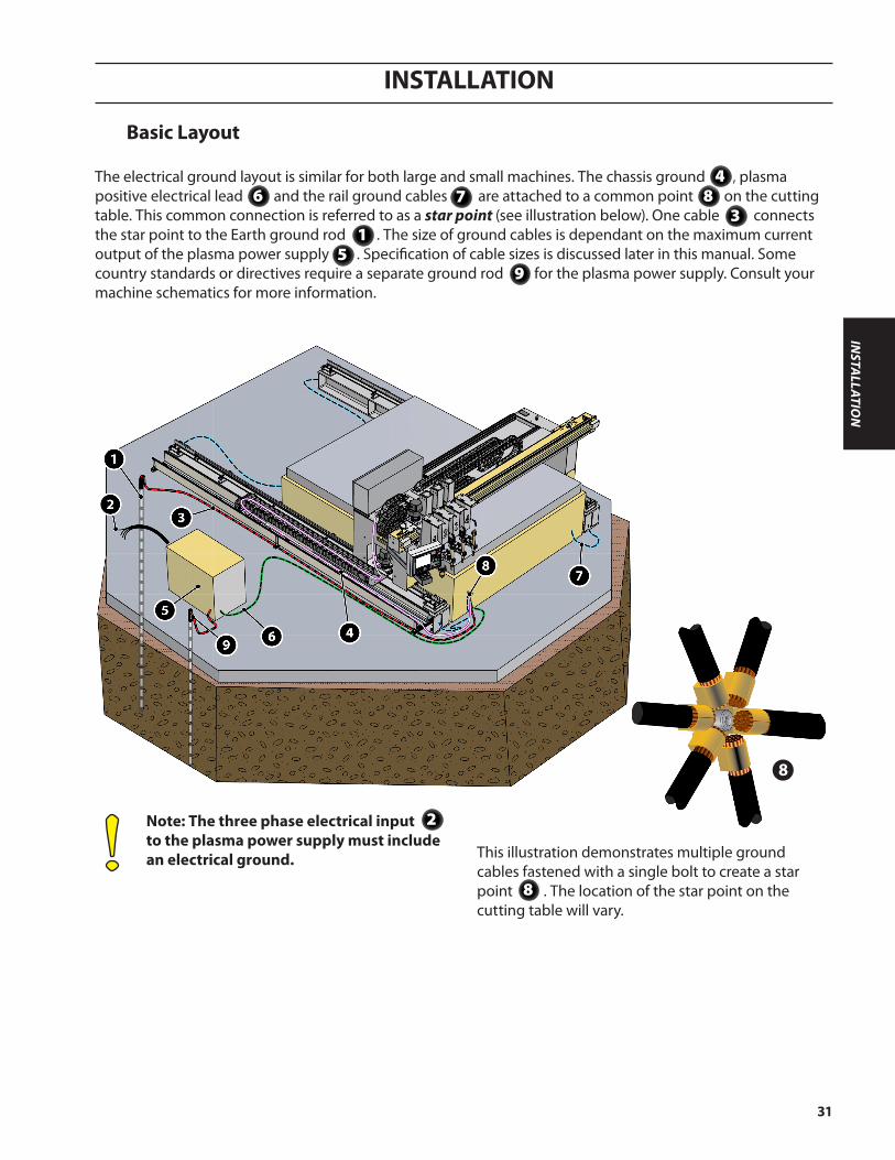
Note: The three phase electrical input to the plasma power supply must include an electrical ground.
Basic Layout
This illustration demonstrates multiple ground cables fastened with a single bolt to create a star point . The location of the star point on the cutting table will vary.
8
2
The electrical ground layout is similar for both large and small machines. The chassis ground , plasma positive electrical lead and the rail ground cables are attached to a common point on the cutting table. This common connection is referred to as a star point (see illustration below). One cable connects the star point to the Earth ground rod . The size of ground cables is dependant on the maximum current output of the plasma power supply . Specification of cable sizes is discussed later in this manual. Some country standards or directives require a separate ground rod for the plasma power supply. Consult your machine schematics for more information.
6 8
9
1
4
3
5
7
8
INSTA
LLATION
INSTALLATION
32
1
23
4
5
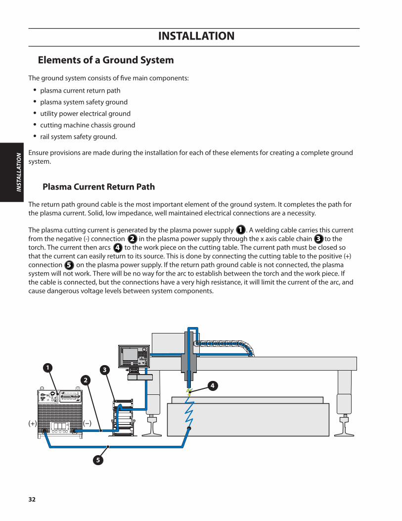
Plasma Current Return Path
The return path ground cable is the most important element of the ground system. It completes the path for the plasma current. Solid, low impedance, well maintained electrical connections are a necessity.
The plasma cutting current is generated by the plasma power supply . A welding cable carries this current from the negative (-) connection in the plasma power supply through the x axis cable chain to the torch. The current then arcs to the work piece on the cutting table. The current path must be closed so that the current can easily return to its source. This is done by connecting the cutting table to the positive (+) connection on the plasma power supply. If the return path ground cable is not connected, the plasma system will not work. There will be no way for the arc to establish between the torch and the work piece. If the cable is connected, but the connections have a very high resistance, it will limit the current of the arc, and cause dangerous voltage levels between system components.
Elements of a Ground System
The ground system consists of five main components:
• plasma current return path
• plasma system safety ground
• utility power electrical ground
• cutting machine chassis ground
• rail system safety ground.
Ensure provisions are made during the installation for each of these elements for creating a complete ground system.
21
43
5
INST
ALL
ATIO
N

INSTALLATION
33
The only way to ensure that all components are at the same voltage level (same potential), and thus eliminate the possibility of being shocked, is to ensure that all interconnections are making good electrical contact. Good electrical contact requires that connections are made with bare metal to metal contact, the connections are very tight, and are protected from rust and corrosion. Use a grinder or wire wheel to clean all paint, rust, and dirt from the surface when connecting cable lugs to any metal surface. Use an electrical joint compound between cable lugs and metal surfaces to prevent future rust and corrosion. Use the largest size bolts, nuts, and washers possible, and tighten fully. Use lock washers to ensure that connections stay tight.
Plasma System Safety Ground
The plasma system safety ground (or ground rod) serves several important purposes. It provides:
• Frame voltage for personnel safety by ensuring that there are no potential differences between system components and building components.
• A stable signal reference for all digital and analog electrical signals on the cutting machine.
• Helps control electromagnetic Interference (or EMI).
• Provides a discharge path for short circuits and high voltage spikes, such as those caused by lightening strikes.
INSTA
LLATION
INSTALLATION
34
Misconception about Earth ground rods.
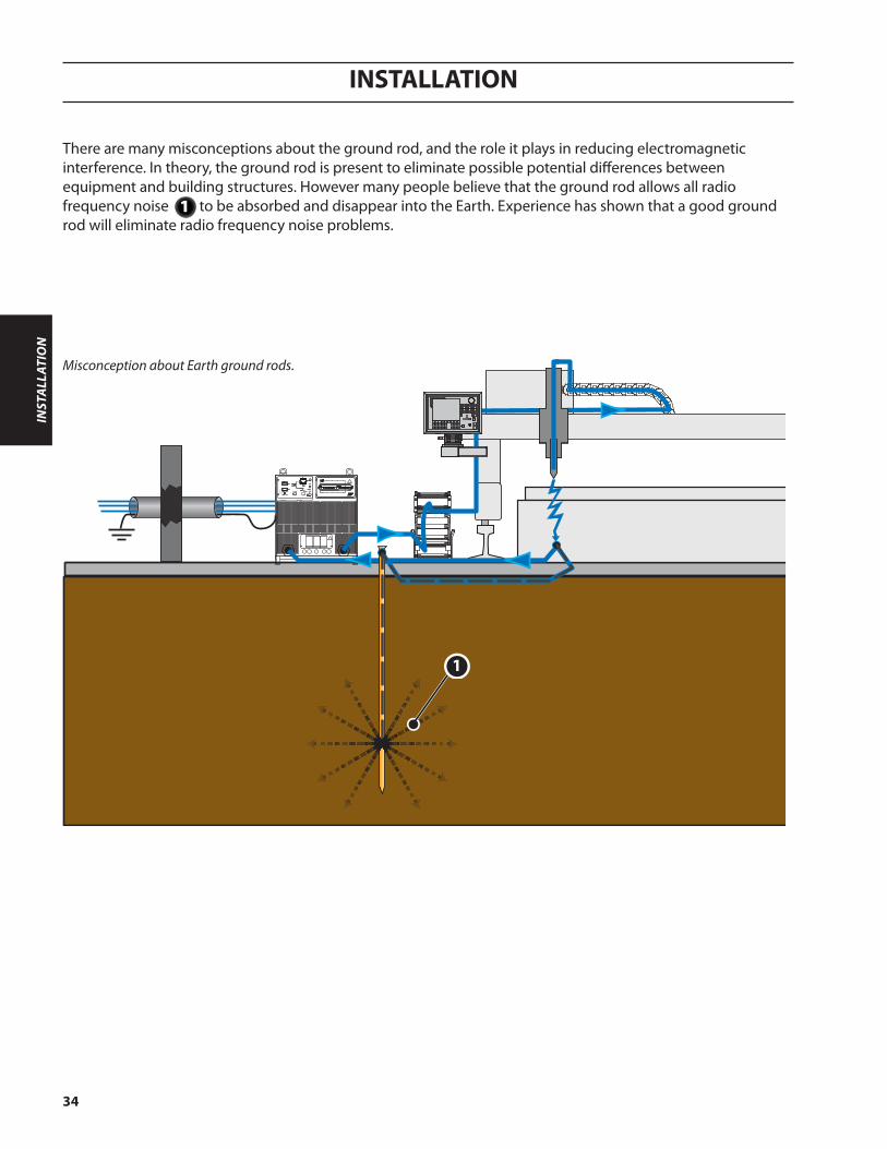
There are many misconceptions about the ground rod, and the role it plays in reducing electromagnetic interference. In theory, the ground rod is present to eliminate possible potential differences between equipment and building structures. However many people believe that the ground rod allows all radio frequency noise to be absorbed and disappear into the Earth. Experience has shown that a good ground rod will eliminate radio frequency noise problems.
1
1
INST
ALL
ATIO
N

INSTALLATION
35
In reality the ground rod is providing a low impedance path by which noise currents may return to their source .
Earth ground rod reality.
12
21
INSTA
LLATION
INSTALLATION
36
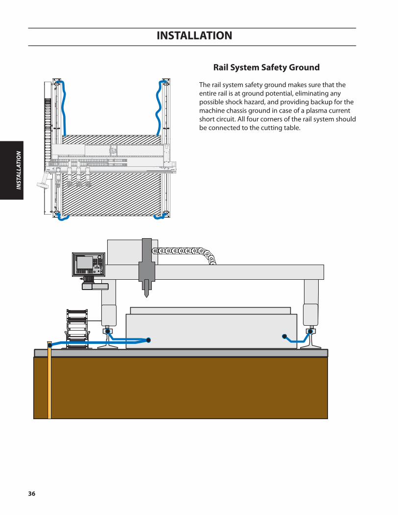
Rail System Safety Ground
The rail system safety ground makes sure that the entire rail is at ground potential, eliminating any possible shock hazard, and providing backup for the machine chassis ground in case of a plasma current short circuit. All four corners of the rail system should be connected to the cutting table.
INST
ALL
ATIO
N

INSTALLATION
37
Earth Ground Rod
The best way to make sure that your Earth ground connection is optimized is to enlist the services of a professional. There are a number of engineering firms which specializes in designing and installing Earth grounding systems. However, if this option cannot be used, then there are several things which can be done to ensure that your Earth ground connection is good:
Ground Rod
The ground rod itself can be optimized in two ways: length and diameter. The longer the grounding rod, the better the connection. The same is true for diameter: the larger the diameter, the better the connection. However, if the soil resistance is very low, then a ground rod longer than 3m [10 feet] does not make a significant difference. Since soil resistivity is rarely as good as it could be, a standard grounding rod should be 25mm [1 inch] in diameter and 6m [20 feet] long.
Soil Resistivity
Soil resistivity can be changed in two ways: by altering the mineral content, the moisture content, or both. The ideal solution to poor soil resistivity is to excavate the immediate area and backfill with conditioned soil additives. In extremely dry areas, the moisture content can be improved by installing a drip system which continually moisturizes the soil surrounding the ground rod. A crude way of affecting soil moisture and content is to use salt water, or rock salt to condition the surrounding soil.
INSTA
LLATION
INSTALLATION
38
1
2
3
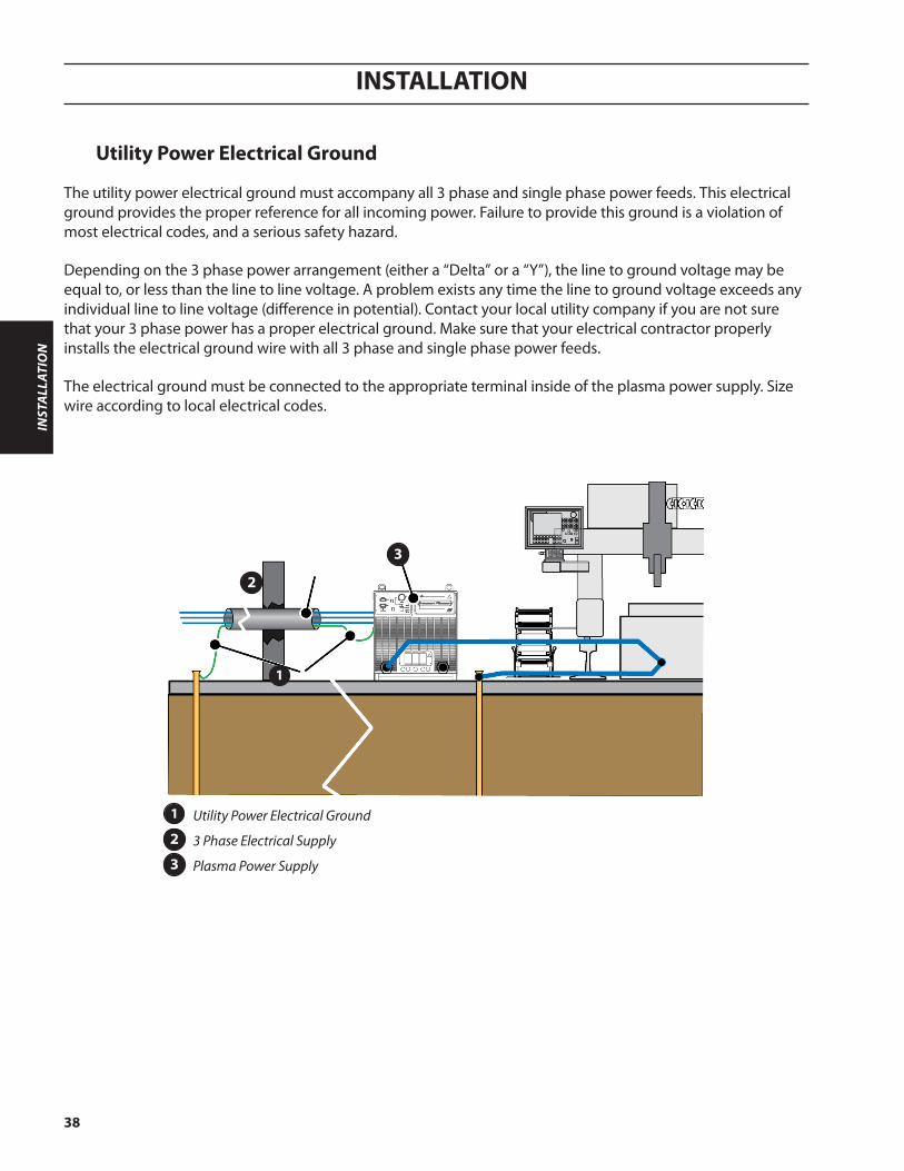
Utility Power Electrical Ground
The utility power electrical ground must accompany all 3 phase and single phase power feeds. This electrical ground provides the proper reference for all incoming power. Failure to provide this ground is a violation of most electrical codes, and a serious safety hazard.
Depending on the 3 phase power arrangement (either a “Delta” or a “Y”), the line to ground voltage may be equal to, or less than the line to line voltage. A problem exists any time the line to ground voltage exceeds any individual line to line voltage (difference in potential). Contact your local utility company if you are not sure that your 3 phase power has a proper electrical ground. Make sure that your electrical contractor properly installs the electrical ground wire with all 3 phase and single phase power feeds.
The electrical ground must be connected to the appropriate terminal inside of the plasma power supply. Size wire according to local electrical codes.
Utility Power Electrical Ground
3 Phase Electrical Supply
Plasma Power Supply
1
2
3
INST
ALL
ATIO
N
INSTALLATION
39
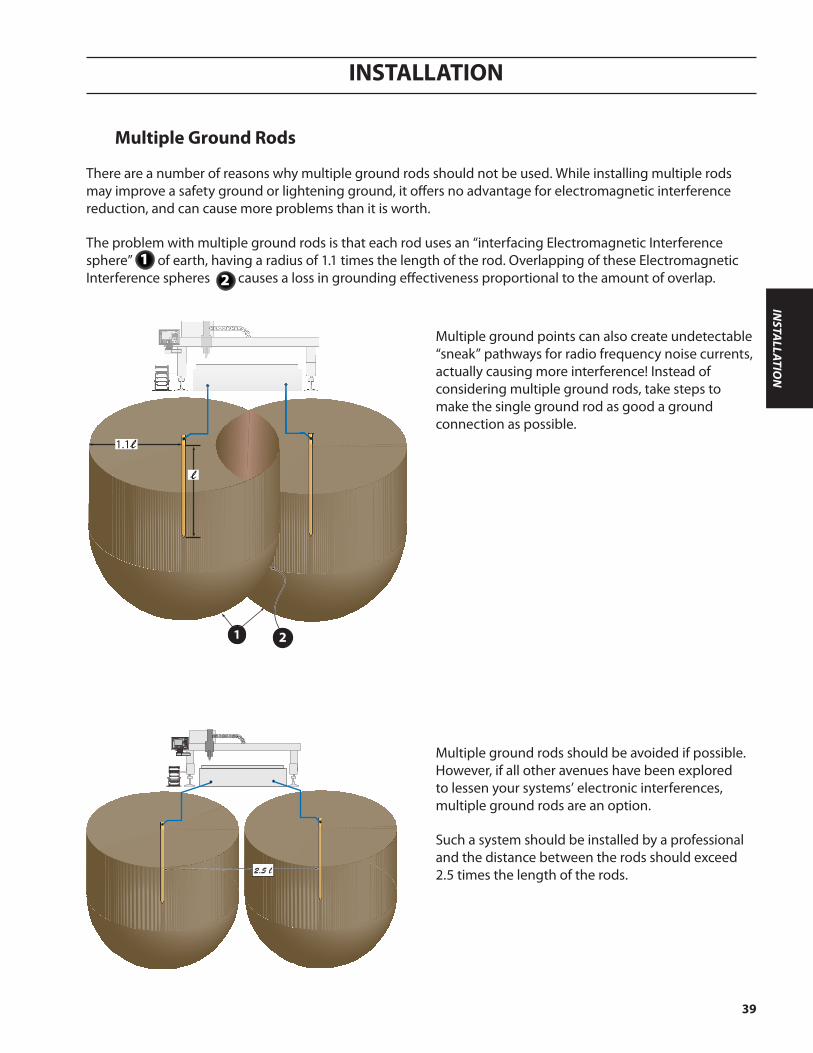
Multiple Ground Rods
There are a number of reasons why multiple ground rods should not be used. While installing multiple rods may improve a safety ground or lightening ground, it offers no advantage for electromagnetic interference reduction, and can cause more problems than it is worth.
The problem with multiple ground rods is that each rod uses an “interfacing Electromagnetic Interference sphere” of earth, having a radius of 1.1 times the length of the rod. Overlapping of these Electromagnetic Interference spheres causes a loss in grounding effectiveness proportional to the amount of overlap.
Multiple ground points can also create undetectable “sneak” pathways for radio frequency noise currents, actually causing more interference! Instead of considering multiple ground rods, take steps to make the single ground rod as good a ground connection as possible.
2.5 l
1.1l
l
1 2
Multiple ground rods should be avoided if possible. However, if all other avenues have been explored to lessen your systems’ electronic interferences, multiple ground rods are an option.
Such a system should be installed by a professional and the distance between the rods should exceed 2.5 times the length of the rods.
21
INSTA
LLATION
INSTALLATION
40
1
7
2
(+)
3
4
5
6
8
9
10
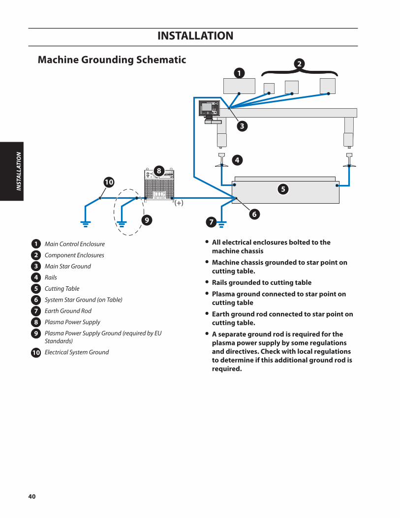
Machine Grounding Schematic
Main Control Enclosure
Component Enclosures
Main Star Ground
Rails
Cutting Table
System Star Ground (on Table)
Earth Ground Rod
Plasma Power Supply
Plasma Power Supply Ground (required by EU Standards)
Electrical System Ground
1
2
3
4
5
6
7
8
9
10
• All electrical enclosures bolted to the machine chassis
• Machine chassis grounded to star point on cutting table.
• Rails grounded to cutting table
• Plasma ground connected to star point on cutting table
• Earth ground rod connected to star point on cutting table.
• A separate ground rod is required for the plasma power supply by some regulations and directives. Check with local regulations to determine if this additional ground rod is required.
INST
ALL
ATIO
N

INSTALLATION
41
Check upon receipt
1. Verify all the system components on your order have been received.
2. Inspect the system components for any physical damage that may have occurred during shipping. If there is evidence of damage, please contact your supplier with the model number and serial number from the nameplate.
Before Installation
Locate the major components to the right position prior to making electrical, gas, and interface connections. Refer to the system interconnection diagrams for major components placement. Ground all major components to earth at one point. To prevent leaks, make sure to tighten all gas and water connections with specific torque.
WARNINGAll installation and service of the electrical and plumbing systems must conform to national and local electrical and plumbing codes. Installation should be performed only by qualified, licensed personnel. Consult your local authorities for any regulation issues.
INSTA
LLATION

INSTALLATION
42
The LCI should be located close to the operator for easy access.
Connect required CAN cables between LCI and other CAN nodes, such as the B4 lifter. CAN connection is always made from left to right, if one node is removed from CAN bus, all nodes on the right need to be shifted to left. After connecting all CAN nodes, a termi-nator is required. Leave all unused CAN ports open.
Connect DB37 cable to port “CNC” on LCI. The other side of DB37, is connected to the customer’s CNC via a male DB37 connector. An optional breakout board may be used.
Connect power from LCI to B4 lifter, if applicable. Make sure the power switch on LCI is off.
Connect power to LCI box.
3.1 Placement of LCI
INST
ALL
ATIO
N

OPERATION
SAFETY
DESCRIPTIO
NIN
STALLATIO
N
OPERATIO
N

OPERATION
44
OPE
RATI
ON

OPERATION
45
4.0 Lift Control Interface
The LCI (Lift Control Interface) is used to interface the ESAB SVHC-2 with the customer CNC using digital I/O.
OPERATIO
N
LCI front view
LCI back view
GND
Note:Chassis must be connected
to the machine ground.
1 2 3 4 5
6
7
8 9 10 11 12
13
1415
16

OPERATION
46
OPE
RATI
ON
LCI Connectors
Item Number Item Description1 AHC Test Only functional in Local mode. Starts automatic height control sequence.
2 IHS Test Only functional in Local mode. Starts initial height sensing test.
3 Local/RemoteThis switch will change the LCI system from being remotely controlled, via the digital inputs from the CNC, to locally controlled via the switches on the Lift Control Interface.
4 Up/Down This switch is a momentary switch which will move the station up or down.
5 Screen Select This switch will allow the user to select different screens.
6 Encoder Wheel with Push Button
This only has an effect in local mode under normal operation and in the set up mode. This wheel will allow you to change the parameter the cursor is currently on. The button will also allow you to see a more detailed error message when on the error log screen.To work the wheel for editing a parameter, push the wheel, move the wheel to change the value, and then press the wheel again to lock in the value.
7 Power Switch This switch will turn on the Lift Control Interface.
8 Input Power Customer supplied input power to LCI. See specifications for power require-ments.
9 AHC Power Power connection for an ESAB lift (B4 or A6).
10 Gas Power Not used.
11 RS232 Not used.
12 ASIOB1 Not used.
13 CNC DB37 connector to interface to customer I/O.
14 AUX Control Not used.
15 CAN Vision 5x Not used.
16 Fuses Replace fuses with same type and size.
4.1 Operation

OPERATION
47
OPERATIO
N
Setup Descriptions
Setup - The “setup screen” on the Lift Control Interface is accessed by having “AHC Test” set to “ON” and “Remote/Lo-cal” set to “LOCAL” when powering up the box. It is exited by turning the power off and then back on. Make sure to reset the switches back to the original state for parameter display. The encoder wheel with pushbutton, is used to select an item and change the values or to select a sub-menu.
An example shown here, is for setting up a Plasma System configured for the following:
Motion Enable Signal meaning
Error Log
Save Constants
Reload Constants
Motion Signal Motion - Motion Enable only goes high when motion is allowed. IHS - Motion Enable goes high when IHS is complete and resets when cycle start goes low.
Error Log The error log stores up to 13 errors at a time reported by the LCI in the order they are detected. These errors are only cleared by selecting “CLEAR”. Select the error, by pushing the pushbutton part of the encoder wheel, to see more details about the error.
Lift Type The lifter type specifies which lift is being used. Available options are: A6 or B4.
VDR Ratio Set to the Voltage Divider Ratio being used.
ULS to Table The distance from the torch tip, when on the upper limit switch, to the top of the table slats. This is in micrometers.
Fast Speed This is the speed at which the lifter will move when not in the slowdown zone, when using height control, or when moving up. The slowdown zone is the plate thickness, plus 25 millimeter, above the table slats.
Slow Speed This is the speed at which the lifter will move when in the slowdown zone or using height control. The slowdown zone is the plate thickness, plus 25 millimeter, above the table slats.
Described below are the various options to be modified before setting up the plasma system for operation:
new pic
Lift TypeVDR RatioUpper Limit Switch to Table (µm)Fast Speed (Relative speed 0-500)Slow Speed (Relative speed 0-500)
OPERATION
48
OPE
RATI
ON
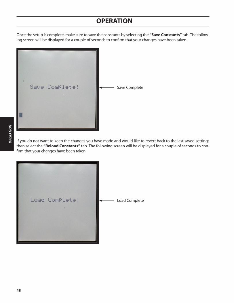
Once the setup is complete, make sure to save the constants by selecting the “Save Constants” tab. The follow-ing screen will be displayed for a couple of seconds to confirm that your changes have been taken.
If you do not want to keep the changes you have made and would like to revert back to the last saved settings then select the “Reload Constants” tab. The following screen will be displayed for a couple of seconds to con-firm that your changes have been taken.
Save Complete
Load Complete
OPERATION
49
OPERATIO
N
Digital Inputs
Digital inputs are to be only turned on with 24 VDC. Any other voltage may damage the board or cause unpre-dictable results. The best method is to send the 24 VDC from the DB37 connector back on the input, via a relay or opto-isolator chip.
Signal Name DescriptionCorner Informs the LCI to block height control.
Cycle Start Start the Height Control Sequence.
Station Up Move the station lifter up.
Station Down Move the station lifter down.
Station On Turn on the station.
Arc On
Arc on from the power source. Used when motion signal is set to motion in the setups screen. This causes the lift to go to piercing height and wait for the piercing timer to expire before going to cutting height and sending Motion Enable.
Digital Outputs
Digital outputs should only be 24 VDC with less than 80 milli-amperes current requirement.
Signal Name Description
Motion Enable/IHS
This signal is high when the arc is on or the process is off, when motion signal is set to Motion in the setup screen. This signal is high when IHS is complete and resets when cycle start is low, when motion signal is set to IHS in the setup screen.
Fault The LCI has detected a problem which required the lifter to stop. Check the error log for details.
Plasma Start Sent after IHS is complete, when motion signal is set to motion in the setup screen. It is reset when cycle start goes low.
Station ULS Station is on the upper limit switch.
Digital I/O

OPERATION
50
OPE
RATI
ON
Editing a Parameter on the Display
Ignition (mm)
Pierce (seconds)
Height Control Screen
Cutting (mm)
Display Screens
On powerup the LCI screen displays the following information for 3 seconds:
Startup Screen
1. Use the encoder wheel to scroll to the parameter.
2. Push the wheel.
3. Turn the wheel to edit the value.
4. Push the wheel again to lock the value.
Software version
Pierce (mm)
Only available when communication is set to none or Local/Remote switch is set to Local.
Thickness (mm)Arc Voltage (volts)
Height Settings

OPERATION
51
OPERATIO
N
CNC Input Screen
Inputs CNC’s Direct Input
ACT(selection program
is currently running)
Station 1 ON 0 0
Cycle Start 0 0
Corner 0 0
Arc ON 0 0
Station UP 0 0
Station DOWN 0 0
CNC Output Screen
Motion Signal options:
IHS - Motion Enable only goes high when IHS is com-plete and resets when cycle start goes low.
Motion - Motion Enable only goes high when motion is allowed.
Defined by motion signalSystem has faultedPlasma Start for simple plasmaStation is on Upper Limit Switch
Outputs

OPERATION
52
OPE
RATI
ON
Remote InterfaceOperation sequence with Motion Signal set to “Motion”:1. Setup the part program that needs to be cut from the CNC.2. Go to the LCI screen and setup the parameters according to the cut data manual for height and piercing timer.3. Once all of the setups have been completed on the LCI, refer to the cut data manual for setting up parameters on
the CNC.4. Execute the program from the CNC.5. The CNC does a purge before Initial Height Sensing, if required.6. The CNC send a “Cycle Start” signal to the LCI.7. The following happens while the CNC waits for motion enable. a. The torch comes down and does the initial height sensing unless the “Corner” signal is high. b. The LCI sets the “Plasma Start” signal high. c. The LCI waits for the “Plasma Arc On” signal to go high. d. The LCI raises to the piercing height unless the “Corner” signal is high. e. The LCI waits a time, from the parameters, for the current to pierce the plate. f. The LCI lowers down to the cutting height unless the “Corner” signal is high. g. The “Motion Enable” signal is returned to the CNC.8. Start moving the machine in the shape desired, turning the corner signal on when not going at full speed for the
parameters.9. Remove the “Cycle Start” signal to the LCI at the end of cut.10. The following happens while the CNC waits for “Motion Enable” to be removed and come back. a. The “Motion Enable” is removed. b. The “Plasma Start” is removed. c. The “Motion Enable” is returned.
Operation sequence with Motion Signal set to “IHS”:1. Setup the part program that needs to be cut from the CNC.2. Go to the LCI screen and setup the parameters according to the cut data manual for height and piercing timer.3. Once all of the setups have been completed on the LCI, refer to the cut data manual for setting up parameters on
the CNC.4. Execute the program from the CNC.5. The CNC does a purge before Initial Height Sensing, if required.6. The CNC send a “Cycle Start” signal to the LCI.7. The torch comes down and does the initial height sensing unless the “Corner” signal is high.8. The “Motion Enable” signal is returned to the CNC.9. The LCI waits for the “Plasma Arc On” signal to go high.10. The LCI raises to the piercing height unless the “Corner” signal is high.11. The LCI waits a time, from the parameters, for the current to pierce the plate.12. The LCI lowers down to the cutting height unless the “Corner” signal is high.13. Start moving the machine in the shape desired, turning the corner signal on when not going at full speed for the
parameters.14. Remove the “Cycle Start” signal to the LCI at the end of cut.15. The “Motion Enable” signal is removed.
4.2 Modes of Operation:

OPERATION
53
OPERATIO
N
Local Interface - Diagnostics OnlyThe local interface is used to test the SVHC-2 system for diagnostic purposes. This allows limited use of the sys-tem and is normally used for troubleshooting. This will disable the CNC’s ability to control the system.
Note: The actual operation of cutting should not be performed while in this mode as the CNC is not in
control of the process.
1. To enable the local interface, the “Local/Remote” switch needs to be in the “Local” position.
2. Parameters can be setup on the screen.
3. Use “IHS Test” to test initail height sensing.
4. Use “AHC Test” to test the sequence.
5. With both “AHC Test” and “IHS Test” off, use station up/down to move the station manually.
Operation sequence:
Ignition (mm)
Pierce (seconds)
Cutting (mm)Pierce (mm)
Thickness (mm)Arc Voltage (volts)
Height Settings

OPERATION
54
OPE
RATI
ON
Interface Wiring
DB37 ConnectorThis cable should be a twisted pair cable with an overall shield attached to the shell on both ends of the cable. It has a DB37 male connector on each end.
Wire No. Signal Name Function1 RS422 RX- Not used
2 RS422/485 TX- Not used
3 RS422/485 GND Not used
4 Digital Output 1 (-) Motion Enable Emitter
5 Digital Output 2 (-) Fault Emitter
6 Digital Output 3 (-) Plasma Start Emitter
7 Digital Output 4 (-) ULS Emitter
8 Digital Output 5 (-) Spare Output Emitter
9 Digital Output 6 (-) Spare Output Emitter
10 Digital Output 7 (-) Spare Output Emitter
11 Digital Output 8 (-) Spare Output Emitter
12 Digital Input 1 Corner
13 Digital Input 2 Spare Input
14 Digital Input 3 Plasma Start On
15 Digital Input 4 Cycle Start
16 Digital Input 10 Spare Input
17 24VDC 24 VDC Power
18 GND Ground
19 Digital Input 5 Spare Input
20 RS422 RX+ Not used
21 RS422/485 TX+ Not used
22 GND Ground
23 Digital Output 1 (+) Motion Enable Collector
24 Digital Output 2 (+) Fault Collector
25 Digital Output 3 (+) Plasma Start Collector
26 Digital Output 4 (+) ULS Collector
27 Digital Output 5 (+) Spare Output Emitter
28 Digital Output 6 (+) Spare Output Emitter
29 Digital Output 7 (+) Spare Output Collector
30 Digital Output 8 (+) Spare Output Collector
31 Digital Input 6 Station Up
32 Digital Input 7 Station Down
33 Digital Input 8 Spare Input
34 Digital Input 9 Spare Input
35 Digital Input 11 Station On
36 GND Ground
37 24VDC 24 VDC Power
FG Field Ground Cable Shield Ground (Connected via the connector shell)
Interface Wiring Descriptions

OPERATION
55
OPERATIO
N
DB37 ConnectorThe customer has two options available for wiring to the DB37 connector shown below:
Connection assemblies for LCI and CNC interface.
Option 1:ESAB provided DB37 cable (Male-free) and customer wires directly to their connection. Not all functions are avail-able with this option.
LCI Box
To Customer provided
DB37 InterfaceDB37 Cable
DB37 CablePart Number Length
0558010157 5 M (16’)
Shown below are two typical ways to use this option, with customer supplied 24 VDC and without.

OPERATION
56
OPE
RATI
ON
DB37 Cable
LCI Box
DB37 Terminal Block Assembly
Manufacturer Part NumberSea Level TB02-KT
Winford BRK37F series
Advantech * ADAM-3937
Example DB37 Breakout boards:
*ESAB recommended part available as ESAB part number 0558009990.
Option 3:ESAB provided DB37 cable (Male-Male) and terminal block assembly for connection to CNC.
Option 2:ESAB provided DB37 cable (Male-Male) and customer provided DB37 (Female) connector. Customer builds their own DB37 Interface for connection to CNC.
LCI Box
To Customer provided
DB37 InterfaceDB37 Cable
DB37 CablePart Number Length Part Number Length0558010071 2 M 0558010076 7 M0558010072 3 M 0558010077 10 M0558010073 4 M 0558010078 15 M0558010074 5 M 0558010079 20 M0558010075 6 M 0558010080 25 M
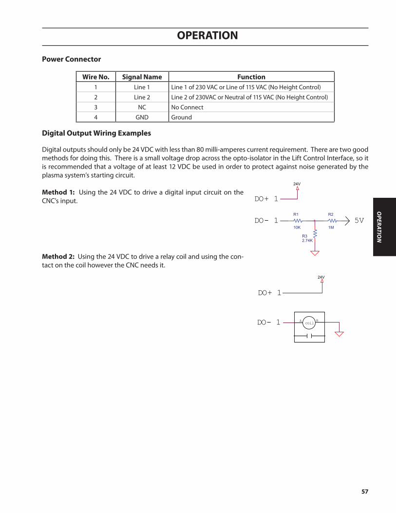
OPERATION
57
OPERATIO
N
Power Connector
Wire No. Signal Name Function1 Line 1 Line 1 of 230 VAC or Line of 115 VAC (No Height Control)
2 Line 2 Line 2 of 230VAC or Neutral of 115 VAC (No Height Control)
3 NC No Connect
4 GND Ground
Digital Output Wiring Examples
R2
1M
R1
10K
R32.74K
5VDO- 1
DO+ 1
24V
DO+ 1
24V
BA coilDO- 1
Optional
Standard
RAS BOX or
CAN PS
B4 Lift
SGB
PGB
External CNCSerial
Digital I/O ICH
(InterfaceControl Hub)
WaterInjection
External Power 230V/3A w/ Height Control
Water Injection
120V/3A w/o Height Control Water Injection
CGC
Method 2: Using the 24 VDC to drive a relay coil and using the con-tact on the coil however the CNC needs it.
R2
1M
R1
10K
R32.74K
5VDO- 1
DO+ 1
24V
DO+ 1
24V
BA coilDO- 1
Optional
Standard
RAS BOX or
CAN PS
B4 Lift
SGB
PGB
External CNCSerial
Digital I/O ICH
(InterfaceControl Hub)
WaterInjection
External Power 230V/3A w/ Height Control
Water Injection
120V/3A w/o Height Control Water Injection
CGC
Digital outputs should only be 24 VDC with less than 80 milli-amperes current requirement. There are two good methods for doing this. There is a small voltage drop across the opto-isolator in the Lift Control Interface, so it is recommended that a voltage of at least 12 VDC be used in order to protect against noise generated by the plasma system’s starting circuit.
Method 1: Using the 24 VDC to drive a digital input circuit on the CNC’s input.

OPERATION
58
OPE
RATI
ON
4.3 Maintenance/Troubleshooting
Error Messages on the LCI Display
Station numberType of ErrorError ID
Error Screen
Error Log Screen
Last received error always shown at top.
This screen can be accessed by scrolling down to the “fault” text and pressing the hand wheel or through the error log screen.
Clear all errors on screen.
Error details
This screen can be accessed by using “Switch Screen” on the LCI and displays a log of the last 13 errors received by the LCI. By moving the cursor to the error and pressing the hand wheel, more details of the error are displayed.

OPERATION
59
OPERATIO
N
Process Errors
Process Errors from System ModulesID DescriptionD Arc Voltage is too high. Check that the torch did not fall into a hole and that the arc voltage calibration is correct.
E Arc Volt is too low. Check that the torch did not crash into the plate or ground and that the arc voltage calibration is correct.
11 The torch has crashed. Please remove obstruction and reset the torch in the torch holder.
13 Initial Height Sensor (IHS) did not complete in the allowed time. Make sure the torch is over a plate and the amplifier is not faulted.
18 The lifter is missing. Please make sure the CAN cable is securely plugged into both the lifter and the LCI Box.
1D The lower limit switch on the lifter has been tripped.
1E-24 Contact service. This is not an error a customer can fix.
29 The display has reset. This can happen during the plasma start sequence. Try moving DB37 cable further away from the torch and power cables away from the power supply.
FF The module’s telegram counters did not match the ICH’s telegram counters. This happens when the ICH misses a telegram, the mod-ule misses a telegram, or the module resets unexpectedly.

OPERATION
60
OPE
RATI
ON
Communication Errors from System ModulesID Description3 Wrong ID or wrong CRC checksum.
9 CRC error during transfer of the station constants.
B Watchdog error.
11 CRC checksum is wrong.
12 Module carried out a reset.
1A Watchdog counter has been exceeded.
1B Output driver has a short circuit.
1C Wrong or no expansion board.
1D CRC error during transfer of the station constants.
1E Send buffer overflow CAN.
1F Receive buffer overflow CAN.
22 Difference between set value and actual value of the digital outputs.
23 CRC error in the calibration data.
2B Junma amplifier reports "Alarm".
2C CRC error in the calibration data.
2D Varying signal statuses on the relay outputs.
2E Over temperature at the heat sink.
2F No motor voltage.
30 CRC checksum of the PLC is not correct.
31 Short circuit on the motor supply cable.
34 Cable fault.
35 Wrong CRC checksum from the printer.
53 CRC checksum of the PLC is not correct.
54 Varying signal statuses on the relay outputs .
59 CRC error during transfer of the station constants.
5A Module carried out a reset.
5B Wrong position sensor.
5C No servo amplifier.
5D Limit switch has been reached.
5E Over current in the servo amplifier.
5F Watchdog counter has been exceeded.
Communication Errors

61
NOTES

62
NOTES

63
REVISION HISTORYoriginal release - 03Nov11

IF YOU DO NOT KNOW WHOM TO CALL
Telephone: (800) ESAB-123 Fax: (843) 664-4462
Hours: 7:30 AM to 5:00 PM EST
orVisit us on the web at http://www.esabna.com
The ESAB web site offersComprehensive Product Information
Material Safety Data SheetsWarranty Registration
Instruction Literature Download LibraryDistributor Locator
Global Company InformationPress Releases
Customer Feedback & Support
A. CUSTOMER SERVICE QUESTIONS: Telephone: (800)362-7080 / Fax: (800) 634-7548 Hours: 8:00 AM to 7:00 PM EST Order Entry Product Availability Pricing Order Information Returns
B. ENGINEERING SERVICE: Telephone: (843) 664-4416 / Fax : (800) 446-5693 Hours: 7:30 AM to 5:00 PM EST Warranty Returns Authorized Repair Stations Welding Equipment Troubleshooting
C. TECHNICAL SERVICE: Telephone: (800) ESAB-123/ Fax: (843) 664-4452 Hours: 8:00 AM to 5:00 PM EST Part Numbers Technical Applications Specifications Equipment Recommendations
D. LITERATURE REQUESTS: Telephone: (843) 664-5562 / Fax: (843) 664-5548 Hours: 7:30 AM to 4:00 PM EST
E. WELDING EQUIPMENT REPAIRS: Telephone: (843) 664-4487 / Fax: (843) 664-5557 Hours: 7:30 AM to 3:30 PM EST Repair Estimates Repair Status
F. WELDING EQUIPMENT TRAINING Telephone: (843)664-4428 / Fax: (843) 679-5864 Hours: 7:30 AM to 4:00 PM EST Training School Information and Registrations
G. WELDING PROCESS ASSISTANCE: Telephone: (800) ESAB-123 Hours: 7:30 AM to 4:00 PM EST
H. TECHNICAL ASST. CONSUMABLES: Telephone : (800) 933-7070 Hours: 7:30 AM to 5:00 PM EST
ESAB Welding & Cutting Products, Florence, SC COMMUNICATION GUIDE - CUSTOMER SERVICES