INSTRUCTION MANUAL - CIRCUTORdocs.circutor.com/docs/M98250001-03.pdf · 2017-09-27 · Instruction...
82
INSTRUCTION MANUAL Dynamic power control CDP-0, CDP-G, CDP-DUO (M98250001-03-17B)
Transcript of INSTRUCTION MANUAL - CIRCUTORdocs.circutor.com/docs/M98250001-03.pdf · 2017-09-27 · Instruction...
INSTRUCTION MANUAL
Dynamic power control
CDP-0, CDP-G, CDP-DUO
(M98250001-03-17B)

2
CDP
Instruction manual

3Instruction manual
CDP
SAFETY PRECAUTIONS
DANGERWarns of a risk, which could result in personal injury or material damage.
ATTENTIONIndicatesthatspecialattentionshouldbepaidtoaspecificpoint.
Follow the warnings described in this manual with the symbols shown below.
If you must handle the unit for its installation, start-up or maintenance, the following should be taken into consideration:
Incorrect handling or installation of the unit may result in injury to personnel as well as damage to the unit. In particular, handling with voltages applied may result in electric shock, which may cause death or serious injury to personnel. Defective installation or maintenance may also leadtotheriskoffire.Read the manual carefully prior to connecting the unit. Follow all installation and maintenance instructions throughout the unit’s working life. Pay special attention to the installation stan-dards of the National Electrical Code.
Refer to the instruction manual before using the unit
In this manual, if the instructions marked with this symbol are not respected or carried out correctly, it can result in injury or damage to the unit and /or installations.
CIRCUTOR,SAreservestherighttomodifyfeaturesortheproductmanualwithoutpriornotification.
DISCLAIMER
CIRCUTOR, SAreservestherighttomakemodificationstothedeviceortheunitspecifica-tions set out in this instruction manual without prior notice.
CIRCUTOR, SA on its web site, supplies its customers with the latest versions of the device specificationsandthemostupdatedmanuals.
www.circutor.com

4
CDP
Instruction manual
CONTENTSSAFETY PRECAUTIONS ���������������������������������������������������������������������������������������������������������������������������������������3DISCLAIMER ����������������������������������������������������������������������������������������������������������������������������������������������������������3CONTENTS �������������������������������������������������������������������������������������������������������������������������������������������������������������4REVISION LOG �������������������������������������������������������������������������������������������������������������������������������������������������������6SYMBOLS ���������������������������������������������������������������������������������������������������������������������������������������������������������������61�- VERIFICATION UPON RECEIPT ����������������������������������������������������������������������������������������������������������������������72�- PRODUCT DESCRIPTION ��������������������������������������������������������������������������������������������������������������������������������73�- INSTALLATION OF THE DEVICE ���������������������������������������������������������������������������������������������������������������������8
3�1�- PRELIMINARY RECOMMENDATIONS ����������������������������������������������������������������������������������������������������8 3�2�- INSTALLATION �����������������������������������������������������������������������������������������������������������������������������������������9 3�3�- DEVICE TERMINALS ��������������������������������������������������������������������������������������������������������������������������������9
3�3�1�- CDP-0 MODEL ������������������������������������������������������������������������������������������������������������������������������������93�3�2�- CDP-G AND CDP-DUO MODELS �����������������������������������������������������������������������������������������������������10
3�4�- CONNECTION DIAGRAMS ��������������������������������������������������������������������������������������������������������������������� 11 3�4�1�- SINGLE-PHASE CONNECTION SCHEME WITH MC3 TRANSFORMERS ����������������������������������������� 11
3�4�2�- SINGLE-PHASE CONNECTION SCHEME WITH MC1 TRANSFORMERS �����������������������������������123�4�3�- THREE-PHASE CONNECTION SCHEME WITH MC3 TRANSFORMERS ��������������������������������������133�4�4�- THREE-PHASE CONNECTION SCHEME WITH MC1 TRANSFORMERS ��������������������������������������143�4�5�- COMMUNICATIONS CONNECTION ������������������������������������������������������������������������������������������������15
4�- OPERATION ���������������������������������������������������������������������������������������������������������������������������������������������������184�1�-OPERATING PRINCIPLE ��������������������������������������������������������������������������������������������������������������������������18
4�1�1�- MEASUREMENT SYSTEM ���������������������������������������������������������������������������������������������������������������184�1�2�- GRID INJECTION PROTECTION RELAY �����������������������������������������������������������������������������������������184�1�3�- CDP-G MODEL : MANAGEMENT OF NON-CRITICAL LOADS ������������������������������������������������������224�1�4�- CDP-DUO MODEL: NETWORK TYPE IDENTIFICATION ����������������������������������������������������������������23
4�2�- APPLICATIONS ����������������������������������������������������������������������������������������������������������������������������������������244�2�1�- SINGLE-PHASE CONNECTION �������������������������������������������������������������������������������������������������������244�2�2�- BASIC THREE-PHASE CONNECTION ��������������������������������������������������������������������������������������������264�2�3�- THREE-PHASE CONNECTION WITH MONITORING ����������������������������������������������������������������������27
4�3�- KEYBOARD ����������������������������������������������������������������������������������������������������������������������������������������������284�4�- LEDs ���������������������������������������������������������������������������������������������������������������������������������������������������������294�5�- DISPLAY ���������������������������������������������������������������������������������������������������������������������������������������������������29
5�- DISPLAY ����������������������������������������������������������������������������������������������������������������������������������������������������������30 5�1�- SINGLE-PHASE MODE ��������������������������������������������������������������������������������������������������������������������������30 5�2�- THREE-PHASE MODE ����������������������������������������������������������������������������������������������������������������������������31
5�2�1�- BASIC THREE-PHASE CONNECTION ��������������������������������������������������������������������������������������������315�2�2�- THREE-PHASE CONNECTION WITH MONITORING ����������������������������������������������������������������������31
5�3�- DISPLAY MENU : MEASURES ����������������������������������������������������������������������������������������������������������������325�4�- DISPLAY WEBSIDE ���������������������������������������������������������������������������������������������������������������������������������34
5�4�1�- CDP-0 MODEL ���������������������������������������������������������������������������������������������������������������������������������������355�4�2�- CDP-G MODEL ����������������������������������������������������������������������������������������������������������������������������������365�4�3�- CDP-DUO MODEL ����������������������������������������������������������������������������������������������������������������������������375�4�4�- DATA LOGGER ���������������������������������������������������������������������������������������������������������������������������������38
6�- CONFIGURATION �������������������������������������������������������������������������������������������������������������������������������������������42 6�1�- CONFIGURATION MENU: NETWORK ���������������������������������������������������������������������������������������������������42 6�1�1�- DHCP ASSIGNMENT ������������������������������������������������������������������������������������������������������������������������42
6�1�2�- NETMASK Y GATEWAY ��������������������������������������������������������������������������������������������������������������������436�1�3�- PRIMARY Y SECONDARY DNS �������������������������������������������������������������������������������������������������������44
6�2�- CONFIGURATION MENU: SYSTEM��������������������������������������������������������������������������������������������������������446�2�1�- DATE AND TIME �������������������������������������������������������������������������������������������������������������������������������44
6�3�- CONFIGURATION WEBSIDE ������������������������������������������������������������������������������������������������������������������456�3�1�- GENERAL PARAMETERS ����������������������������������������������������������������������������������������������������������������466�3�2�- POWER CONTROL & DATA LOGGER : INVERTER �����������������������������������������������������������������������476�3�3�- POWER CONTROL & DATA LOGGER : CONTROL �����������������������������������������������������������������������496�3�4�- POWER CONTROL & DATA LOGGER : REVERSE CURRENT RELAY�����������������������������������������526�3�5�- POWER CONTROL & DATA LOGGER : AUXILIAR LOADS RELAYS �������������������������������������������536�3�6�- POWER CONTROL & DATA LOGGER : DATA LOGGER ���������������������������������������������������������������546�3�7�- ANALYZERS SETUP : LOAD ANALYZER ���������������������������������������������������������������������������������������546�3�8�- ANALYZERS SETUP : GRID ANALYZER ����������������������������������������������������������������������������������������55

5Instruction manual
CDP
6�3�9�- ANALYZERS SETUP : PV ANALYZER ���������������������������������������������������������������������������������������������556�3�10�- ANALYZERS SETUP : COMUNICATIONS �������������������������������������������������������������������������������������566�3�11�- NETWORK & SECURITY SETUP : NETWORK �����������������������������������������������������������������������������566�3�12�- NETWORK & SECURITY SETUP : SECURITY ������������������������������������������������������������������������������57
6�3�13�- SAVE SETUP, LOAD DEFAULT SETUP y RESET CDP ����������������������������������������������������������������58 7�- CDP-G MODEL : OPERATING EXAMPLES ���������������������������������������������������������������������������������������������������59
7�1�- SINGLE-PHASE INSTALLATION WITH 1 LOAD TO BE CONNECTED �����������������������������������������������59 7�2�- SINGLE-PHASE INSTALLATION WITH 3 LOADS TO BE CONNECTED ���������������������������������������������62
8�- MODBUS MAP �����������������������������������������������������������������������������������������������������������������������������������������������68 8�1�- MEASURE PARAMETERS ���������������������������������������������������������������������������������������������������������������������68
8�1�1�- POWER AND REGULATION PERCENTAGE �����������������������������������������������������������������������������������688�1�2�- ENERGÍA, TENSIÓN Y CORRIENTE �����������������������������������������������������������������������������������������������688�1�3�- PARAMETERS MEASURED IN THE LOAD �������������������������������������������������������������������������������������688�1�4�- PARAMETERS MEASURED IN THE GRID ��������������������������������������������������������������������������������������698�1�5�- PHOTOVOLTAIC PARAMETERS �����������������������������������������������������������������������������������������������������708�1�6�- DEVICE INFORMATION ��������������������������������������������������������������������������������������������������������������������70
8�2�- CONFIGURATION PARAMETERS ����������������������������������������������������������������������������������������������������������718�2�1�- STATE OF RELAYS ���������������������������������������������������������������������������������������������������������������������������71
8�2�2�- OTHER PARAMETERS ���������������������������������������������������������������������������������������������������������������������71 9�- TECHNICAL FEATURES ��������������������������������������������������������������������������������������������������������������������������������7210�- TECHNICAL SERVICE ����������������������������������������������������������������������������������������������������������������������������������7411�- GUARANTEE �������������������������������������������������������������������������������������������������������������������������������������������������7412�- CE CERTIFICATE ������������������������������������������������������������������������������������������������������������������������������������������7513�- UNE 217001 IN CERTIFICATE ����������������������������������������������������������������������������������������������������������������������78

6
CDP
Instruction manual
REVISION LOG
Table 1: Revision logDate Revision Description06/13 M98250001-03-13A Original version07/14 M98250001-03-14A General revision09/14 M98250001-03-14B Introduction model CDP-G
01/15 M98250001-03-15AChanges in the following sections:
3.5.2. - 4.1.2. - 4.6. - 5. - 5.2. - 5.3. - 6.1.1. - 6.1.2.1.6.1.2.3. - 6.1.2.5. - 6.1.5. - Appendix A
02/17 M98250001-03-17AChanges in the following sections:
3.3. - 3.4. - 4.1. - 4.1.3. - 4.1.4. - 4.2. - 4.2.1. - 5.2. - 5.4. - 6.1.- 6.2. - 6.3.3. - 7.
09/17 M98250001-03-17B Changes in the following sections:3.3.1. - 3.3.2. - 4.3.
Note : Device images are for illustrative purposes only and may differ from the actual device.
SYMBOLS
Table 2: Symbols�Symbols Description
Compliant with the relevant European standards.
Corriente continua.
~ Corriente alterna.
7Instruction manual
CDP
1�- VERIFICATION UPON RECEIPT
Check the following points when you receive the device:
a)Thedevicemeetsthespecificationsdescribedinyourorder. b) The device has not suffered any damage during transport. c) Perform an external visual inspection of the unit prior to switching it on. d) Check that it has been delivered with the following: - An installation guide.
If any problem is noticed upon reception, immediately contact the transport company and/or CIRCUTOR’s after-sales service.
2�- PRODUCT DESCRIPTION
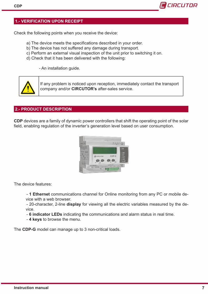
CDP devices are a family of dynamic power controllers that shift the operating point of the solar field,enablingregulationoftheinverter’sgenerationlevelbasedonuserconsumption.
The device features:
- 1 Ethernet communications channel for Online monitoring from any PC or mobile de-vice with a web browser. - 20-character, 2-line display for viewing all the electric variables measured by the de-vice. - 6 indicator LEDs indicating the communications and alarm status in real time.
- 4 keys to browse the menu. The CDP-G model can manage up to 3 non-critical loads.

8
CDP
Instruction manual
3�- INSTALLATION OF THE DEVICE
3.1.- PRELIMINARY RECOMMENDATIONS
The device must only be installed and maintained by authorised and quali-fied personnel.
In order to use the device safely, it is critical that individuals who handle it follow the safety measures set out in the standards of the country where it is being used, use the necessary personal protective equipment, and pay attention to the vari-ous warnings indicated in this instruction manual.
The CDPdevicemustbeinstalledbyauthorisedandqualifiedstaff.The power supply plug must be disconnected and measuring systems switched off before han-dling, altering the connections or replacing the device. It is dangerous to handle the device while it is powered.
Also, it is critical to keep the cables in perfect condition in order to avoid accidents, personal injury and damage to installations.
The manufacturer of the device is not responsible for any damage resulting from failure by the user or installer to observe the warnings and/or recommendations set out in this manual, nor for damage resulting from the use of non-original products or accessories or those made by other manufacturers.
If an anomaly or malfunction is detected in the device, do not use the device to take any meas-urements.
Inspect the work area before taking any measurements. Do not take measurements in danger-ous areas or where there is a risk of explosion.
Disconnect the device from the power supply (unit and measuring system power supply) before maintaining, repairing or handling the unit’s connections.Please contact the after-sales service if you suspect that there is an operational fault in the device.

9Instruction manual
CDP
3.2.- INSTALLATION
Install the device on a DIN 46277 rail (EN 50022). All connections are located inside the electric panel.
Terminals, opening covers or removing elements can expose parts that are haz-ardous to the touch while the device is powered. Do not use the device until it is fully installed.
3.3.- DEVICE TERMINALS
3�3�1�- CDP-0 MODELTable 3:List of CDP-0 terminals�
Device terminals1: VL1, Voltage measurement 22: L3, current measurement3: VL2, Voltage measurement 23: L2, current measurement5: VL3, Voltage measurement 24: L1, current measurement6: N, Voltage measurement neutral 28: Digital input 117: Auxiliary power supply, Vac 29: Digital input 218: Auxiliary power supply, Vac 30: Digital input 319: -, Auxiliary power supply, Vdc 31: Digital input 420: +, Auxiliary power supply, Vdc 36: C, Digital inputs common21: C, Current measurement common
ON
ACTCOM 1COM 2ALARMOK
LINK
+ 12 V -DC PowerSupply
C 4 3 2 1INPUTS
Figure 1: CDP-0 terminals�

10
CDP
Instruction manual
3�3�2�- CDP-G AND CDP-DUO MODELS
Table 4:List of terminals: DCP-G and CDP-DUO�Device terminals
1: VL1, Voltage measurement 17: Auxiliary power supply, Vac3: VL2, Voltage measurement 18: Auxiliary power supply, Vac5: VL3, Voltage measurement 19: -, Auxiliary power supply, Vdc6: N, Voltage measurement neutral 20: +, Auxiliary power supply, Vdc8: Auxiliary relay 4 / Inverse current relay (NC) 21: C, Current measurement common9: Auxiliary relay 4 / Inverse current relay (COM) 22: L3, current measurement10: Auxiliary relay 4 / Inverse current relay (NO) 23: L2, current measurement11: Auxiliary relay 3 (COM) 24: L1, current measurement12: Auxiliary relay 3 (NO) 28: Digital input 113: Auxiliary relay 2 (COM) 29: Digital input 214: Auxiliary relay 2 (NO) 30: Digital input 315: Auxiliary relay 1 (COM) 31: Digital input 416: Auxiliary relay 1 (NO) 36: C, Digital inputs common
ON
ACTCOM 1COM 2ALARMOK
LINK
+ 12 V -DC PowerSupply
C 4 3 2 1INPUTS
Figure 2: Terminals: CDP-G and CDP-DUO�

11Instruction manual
CDP
3.4.- CONNECTION DIAGRAMS
The CDP measures current using the MC1 or MC3 transformers with a secondary current of 250 mA
Table 5: Measurement transformers�
Measurement transformersMC3 Three-phase transformer. MC1 Single-phase transformer.
3�4�1�- SINGLE-PHASE CONNECTION SCHEME WITH MC3 TRANSFORMERS
VL13P
12P
11P
1
3P2
2P2
1P2
VL2
VL3
Brow
n /G
reen
Gre
y / P
ink
Gre
en /W
hite
Red
/cBl
ue
L1
N
N
+ 12 V -DC PowerSupply
CDP-0
OK
ON
ACTCOM 1
ALARM
LINK
COM 2
Auxiliary Power Supply ~
Current consumedby the user
Current generatedby the inverter
Current consumed from the grid
Figure 3:Single-phase connection scheme with MC3 transformers�
Note: The device has terminals for supplying it either AC voltage (terminals 17 and 18 of Ta-ble 3) or DC voltage (terminals 19 y 20 of Table 3).

12
CDP
Instruction manual
3�4�2�- SINGLE-PHASE CONNECTION SCHEME WITH MC1 TRANSFORMERS
VL1
VL2
VL3
L1
N
N
+ 12 V -DC PowerSupply
CDP-0
OK
ON
ACTCOM 1
ALARM
LINK
COM 2 1
S1 1
S2
2S1
2S2
MC
1
1S1
1S2
2S
1 2
S2
MC
1
1S1
1S2
2S
1 2
S2
MC
1
Current consumedby the user
Auxiliary Power Supply ~
Current consumed from the grid
Current generatedby the inverter
Figure 4:Single-phase connection scheme with MC1 transformers�
Note: The device has terminals for supplying it either AC voltage (terminals 17 and 18 of Ta-ble 3) or DC voltage (terminals 19 y 20 of Table 3).
Table 6:List of terminals of the MC1 transformer�
Terminal MC1-20 MC1-301S1 Common Common1S2 Scale 150 A Scale 250 A2S1 Scale 200 A Scale 400 A2S2 Scale 250 A Scale 500 A

13Instruction manual
CDP
3�4�3�- THREE-PHASE CONNECTION SCHEME WITH MC3 TRANSFORMERS
VL1
3P1
2P1
1P1
3P2
2P2
1P2
VL2
VL3
Brow
n /G
reen
Gre
y / P
ink
Gre
en /W
hite
Red
/cBl
ue
L1
N
N
+ 12 V -DC PowerSupply
CDP-0
OK
ON
ACTCOM 1
ALARM
LINK
COM 2
L2
L3
Current consumedby the user
Auxiliary Power Supply ~
Figure 5:Three-phase connection scheme with MC3 transformers�
Note: The device has terminals for supplying it either AC voltage (terminals 17 and 18 of Ta-ble 3) or DC voltage (terminals 19 y 20 of Table 3).

14
CDP
Instruction manual
3�4�4�- THREE-PHASE CONNECTION SCHEME WITH MC1 TRANSFORMERS
VL1
VL2
VL3
L1
N
N
+ 12 V -DC PowerSupply
CDP-0
OK
ON
ACTCOM 1
ALARM
LINK
COM 2
1S1
1S2
2S
1 2
S2
MC
1
1S1
1S2
2S
1 2
S2
MC
1
1S1
1S2
2S
1 2
S2
MC
1
L2
L3
Current consumedby the user
Auxiliary Power Supply ~
Figure 6:Three-phase connection scheme with MC1 transformers�
Note: The device has terminals for supplying it either AC voltage (terminals 17 and 18 of Ta-ble 3) or DC voltage (terminals 19 y 20 of Table 3).
Table 7:List of terminals of the MC1 transformer�
Terminal MC1-20 MC1-301S1 Common Common1S2 Scale 150 A Scale 250 A2S1 Scale 200 A Scale 400 A2S2 Scale 250 A Scale 500 A

15Instruction manual
CDP
3�4�5�- COMMUNICATIONS CONNECTION
The CDP has three communications channels referred to as R1, R2 and R3.
R1, Ethernet communications channel. R2, Channel for communicating with the inverter: RS-422 / RS-485 / RS-232. R3, Channel for communicating with the external measuring devices:RS-485.
ON
ACTCOM 1COM 2ALARMOK
LINK
1 2 3 4 5 6 7
Communications channel R1 Communications channel R2 and R3
Figure 7: Communications channels�
3�4�5�1�- Communications channel R2
The R2 channel is used for communications with the inverter.
Table 8: Description of the R2 channel terminals�
TerminalsCommunication protocol
RS-422 RS-485 RS-2321 TxD + A+ CTS2 RxD - - RTS3 TxD - B- RX4 RxD + - TX5 GND GND GND
Note: For the proper working of RS-485 communications, always connect the GND terminal.

16
CDP
Instruction manual
3�4�5�2�- Communications channel R3
The R2 channel is used to create a network with the auxiliary units that help measure the power in three-phase installations.
Table 9: Description of the R3 channel terminals�
TerminalsCommunication protocol
RS-4855 GND6 B-7 A+
Note: For the proper working of RS-485 communications, always connect the GND terminal.
3�4�5�3�- Connection diagram
Connection diagram with an inverter through channel R2, RS-422 protocol and a CVM Mini, channel R3, RS-485 protocol.
ON
ACTCOM 1COM 2ALARMOK
LINK
1 2 3 4 5 6 7
Tx +
Tx -Rx -
Rx +
A+B -
GND
RS-422 RS-485
Figure 8: Communication connection diagram�
Table 10 shows the connections between the CDP, R3 communications channel and the CVM Mini.
Table 10:Connection between CDP and the CVM Mini�
CDP CVM MiniTerminal Description Terminal Description
5 GND 2 GND6 B- 1 B-7 A+ 3 A+

17Instruction manual
CDP
To ensure that the CDP can communicate with the external CVM Mini,thismustbeconfiguredas per Table 11.
Table 11: Configuration of the external CVM Mini.
Configuration of the external CVM MiniParameter Value
Peripherical number ConfigurableBaud rate Configurable
Bits 8Parity No
Stop bits 1
Note : It is recommended that a category 5e FTP cable or higher is used and a twisted pair must be used for each earth leakage signal pair.
18
CDP
Instruction manual
4�- OPERATION
4.1.-OPERATING PRINCIPLE
One of the main features of the CDPisthatitcanmeasurealltheenergyflowsoftheinstalla-tion:
Energy consumed by the user. Energy generated by the inverter. Energy consumed or injected into the grid.
Theinverterpowermustbeconfiguredinthedeviceand,throughacommunicationschannel,the CDP can adapt generation to energy consumption with the aim of achieving zero grid in-jection
The CDP generates a database with all the power and energy information for every measuring point, including the inverter’s regulation percentage.
The following functions have also been implemented in the CDP:
Grid injection alarm control. Management of non-critical loads, CDP-G model.
Dualconfigurationofthenetworkparametersforhybridinstallations,CDP-DUO mo-del.
4�1�1�- MEASUREMENT SYSTEM
The CDP measures the user’s voltage and current and uses these values to calculate the consumed power. If the power generated by the inverter differs from that consumed, the unit changes the inverter’s working setpoint to adjust it to the real-time needs of the installation.
4�1�2�- GRID INJECTION PROTECTION RELAY
If measuring the power consumed from the grid, both in single-phase and three-phase installations, the CDP can control a redundant grid current injection protection relay. Relay number 4 is used for this function, by default the relay status is NC (terminals 8, 9 and 10 to the Table 3).
Table 12 describes the parameters that can be configured in the CDP in relation to the control tasks of this function:
Table 12: Configuration parameters for the grid injection protection relay.
Configuration parameters for the grid injection protection relayParameter Description Units
Enable inverse current relay Activation of the inverse current protection -Stop time Grid injection validation time s
Reconnection time Reconnection time sMax. Disconnections Maximum number of reconnections -Disconnect� Timeout Maximum reconnection time s
19Instruction manual
CDP
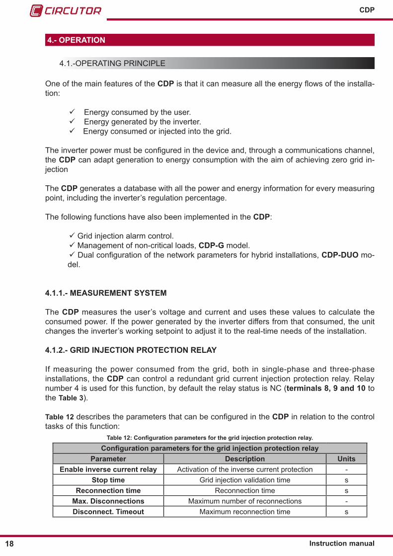
If power is injected into the grid during the period defined by the Stop time parameter, relay number 4 is desactivated. (If Stop time is programmed with the value 0 this function remains deactivated). In addition, an orange alarm icon appears on the web site, as shown in Figure 9:
White alarmicon
Orange alarmicon
Red alarmicon
Figure 9: Hardware control alarm activated�
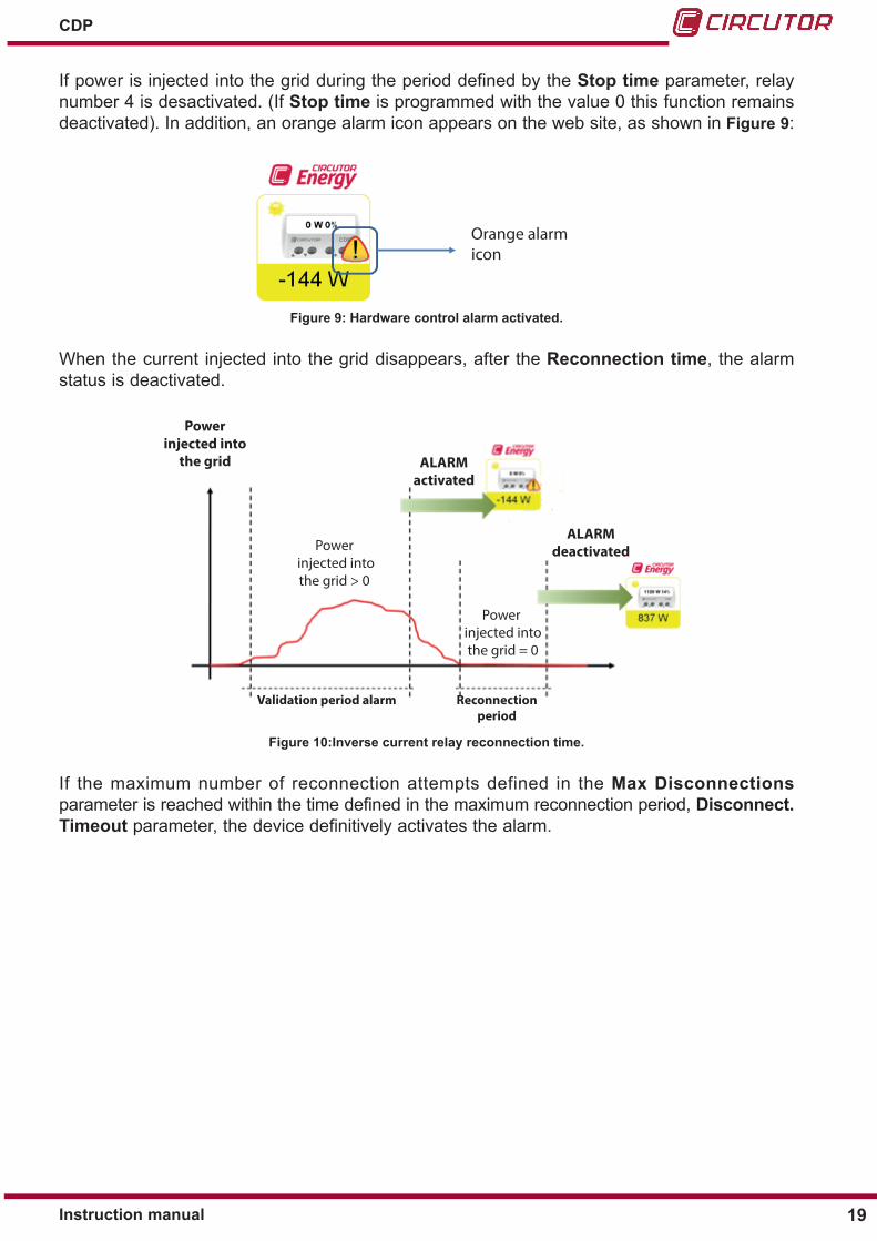
When the current injected into the grid disappears, after the Reconnection time, the alarm status is deactivated.
Powerinjected into
the grid ALARMactivated
ALARMdeactivated
Power injected into the grid = 0
Reconnectionperiod
Validation period alarm
Power injected into the grid > 0
Figure 10:Inverse current relay reconnection time�
If the maximum number of reconnection attempts defined in the Max Disconnections parameter is reached within the time defined in the maximum reconnection period, Disconnect� Timeout parameter, the device definitively activates the alarm.

20
CDP
Instruction manual
Powerinjected into
the grid
Permanent status alarmRedundant state relay
ALARMactivated
Valid
atio
npe
riod
Reco
nnec
tion
peri
od
Reco
nnec
tion
peri
od
Reco
nnec
tion
peri
od
Valid
atio
npe
riod
Valid
atio
npe
riod
Figure 11:Alarm reconnection sequence�
The following indications appear in the CDP when the reconnection sequence has been completed:
Alarm LED: The alarm LED is activated in the CDP indicating that power is being injected into the grid and that the reconnection sequence is complete.
When the alarm is activated the red LED
is on
Figure 12: Inverse current relay alarm�
Device display: A screen appears on the CDP indicating that the device has activated the inverse current protection relay, and there is an option to unlock it. The option NO appears on thehomescreen;thiscanbechangedwiththe▲and▼ keys to YES. Press the OK key to validate the selected option.
Figure 13:Inverse current alarm screen�

21Instruction manual
CDP
If NO is selected, the alarm remains permanently activated. If the OK key is pressed on the main screen, the option to deactivate the inverse current alarm is displayed.
Figure 14: Inverse current alarm display�
If the inverse current alarm is activated, although the device turns off and on again, this condition is memorised and the alarm notification will appear on the screen indicating that it is possible to unlock it.
Web side: The icon is red indicating that the alarm has been activated.
White alarmicon
Orange alarmicon
Red alarmicon
Figure 15:Inverse current relay alarm activated�
If you press above the alarm icon a message will appear asking if you want to deactivate the grid injection alarm. You can accept or cancel this option as shown in Figure 16.
Figure 16:Deactivating the alarm on the web site�

22
CDP
Instruction manual
4�1�3�- CDP-G MODEL : MANAGEMENT OF NON-CRITICAL LOADS
This functionality allows you to add non-critical loads depending on if more power can be ob-tained from the inverter. This management can be manual or dynamic and is carried out through the use of the system’s auxiliary relays (terminals 11 to 16 of Table 3).
Manual managementisperformedfromtheconfigurationwebsite,fromwhichyoucanviewand modify the status of the relays (Figure 17).
Figure 17:Manual management of non-critical loads from the web site�
When managing dynamic control, the loads are connected based on having met two condi-tions:
Condition 1: Setpoint value ≤ Maximum modulation value
𝑃𝑃𝑃𝑃𝑃𝑃𝑃𝑃𝑃𝑃𝑃𝑃𝑃𝑃𝑃𝑃𝑃𝑃𝑃𝑃𝑃𝑃𝑃𝑃𝑃𝑃𝑃𝑃𝑃𝑃𝑃𝑃𝑃𝑃 𝑃𝑃𝑃𝑃𝑖𝑖𝑃𝑃𝑖𝑖𝑖𝑖𝑃𝑃𝑖𝑖
𝑥𝑥100 ≤ 𝑀𝑀𝑃𝑃𝑥𝑥.𝑃𝑃𝑃𝑃𝑃𝑃𝑃𝑃𝑃𝑃𝑃𝑃𝑖𝑖𝑃𝑃𝑃𝑃𝑃𝑃 𝑖𝑖𝑃𝑃𝑃𝑃𝑃𝑃𝑃𝑃
𝑃𝑃𝑐𝑐𝑐𝑐𝑐𝑐𝑐𝑐𝑐𝑐𝑐𝑐𝑐𝑐𝑐𝑐𝑃𝑃𝑐𝑐𝑚𝑚𝑚𝑚𝑚𝑚𝑉𝑉
⋅ 100
𝑃𝑃Grid
∑𝑃𝑃CG· 100
𝑃𝑃𝑃𝑃𝑃𝑃𝑃𝑃𝑃𝑃𝑃𝑃𝑃𝑃𝑃𝑃𝑃𝑃𝑃𝑃𝑃𝑃𝑃𝑃𝑃𝑃𝑃𝑃𝑃𝑃𝑃𝑃𝑃𝑃 𝑃𝑃𝑃𝑃𝑖𝑖𝑃𝑃𝑖𝑖𝑖𝑖𝑃𝑃𝑖𝑖
𝑥𝑥100 ≤ 𝑀𝑀𝑃𝑃𝑥𝑥.𝑀𝑀𝑃𝑃𝑃𝑃𝑃𝑃𝑃𝑃𝑃𝑃𝑖𝑖𝑃𝑃𝑃𝑃𝑃𝑃 𝑉𝑉𝑃𝑃𝑃𝑃𝑃𝑃𝑃𝑃
( 400010000
𝑥𝑥100 = 40%) 40% ≤ 90% This condition is met
𝑷𝑷𝒈𝒈𝒈𝒈𝒈𝒈𝒈𝒈∑𝑷𝑷𝒄𝒄𝒄𝒄𝒄𝒄𝒄𝒄𝒄𝒄𝒄𝒄𝒄𝒄𝒄𝒄𝒈𝒈 𝒈𝒈𝒄𝒄𝒓𝒓𝒓𝒓𝒓𝒓𝒓𝒓
< 𝑀𝑀𝒓𝒓𝒂𝒂 𝑮𝑮𝒈𝒈𝒈𝒈𝒈𝒈 𝒄𝒄𝒄𝒄𝒄𝒄𝒄𝒄𝒈𝒈𝒈𝒈𝒄𝒄𝒄𝒄𝒄𝒄𝒈𝒈𝒄𝒄𝒄𝒄
( 30005000
= 60%) 60% ≤ 20% This condition is not met
( 06000
= 0%) 0% ≤ 50% This condition is met
( 600010000
𝑥𝑥100 = 60%) 60% ≤ 90% This condition is met
( 08000
= 0%) 0% ≤ 50% This condition is met
( 800010000
𝑥𝑥100 = 80%) 80% ≤ 90% This condition is met
( 100010000
= 10%) 10% ≤ 50% This condition is met
Equation 1: Condition 1 for load connection�
Where the Maximum modulation value is the ratio between the power consumed by the user andthemaximumpowerthatcanbeobtainedbytheconfiguredinverters.Inotherwords,themaximum modulation value is (%) :
𝑃𝑃𝑃𝑃𝑃𝑃𝑃𝑃𝑃𝑃𝑃𝑃𝑃𝑃𝑃𝑃𝑃𝑃𝑃𝑃𝑃𝑃𝑃𝑃𝑃𝑃𝑃𝑃𝑃𝑃𝑃𝑃𝑃𝑃 𝑃𝑃𝑃𝑃𝑖𝑖𝑃𝑃𝑖𝑖𝑖𝑖𝑃𝑃𝑖𝑖
𝑥𝑥100 ≤ 𝑀𝑀𝑃𝑃𝑥𝑥.𝑃𝑃𝑃𝑃𝑃𝑃𝑃𝑃𝑃𝑃𝑃𝑃𝑖𝑖𝑃𝑃𝑃𝑃𝑃𝑃 𝑖𝑖𝑃𝑃𝑃𝑃𝑃𝑃𝑃𝑃
𝑃𝑃𝑐𝑐𝑐𝑐𝑐𝑐𝑐𝑐𝑐𝑐𝑐𝑐𝑐𝑐𝑐𝑐𝑃𝑃𝑐𝑐𝑚𝑚𝑚𝑚𝑚𝑚𝑉𝑉
⋅ 100
𝑃𝑃Grid
∑𝑃𝑃CG· 100
𝑃𝑃𝑃𝑃𝑃𝑃𝑃𝑃𝑃𝑃𝑃𝑃𝑃𝑃𝑃𝑃𝑃𝑃𝑃𝑃𝑃𝑃𝑃𝑃𝑃𝑃𝑃𝑃𝑃𝑃𝑃𝑃𝑃𝑃 𝑃𝑃𝑃𝑃𝑖𝑖𝑃𝑃𝑖𝑖𝑖𝑖𝑃𝑃𝑖𝑖
𝑥𝑥100 ≤ 𝑀𝑀𝑃𝑃𝑥𝑥.𝑀𝑀𝑃𝑃𝑃𝑃𝑃𝑃𝑃𝑃𝑃𝑃𝑖𝑖𝑃𝑃𝑃𝑃𝑃𝑃 𝑉𝑉𝑃𝑃𝑃𝑃𝑃𝑃𝑃𝑃
( 400010000
𝑥𝑥100 = 40%) 40% ≤ 90% This condition is met
𝑷𝑷𝒈𝒈𝒈𝒈𝒈𝒈𝒈𝒈∑𝑷𝑷𝒄𝒄𝒄𝒄𝒄𝒄𝒄𝒄𝒄𝒄𝒄𝒄𝒄𝒄𝒄𝒄𝒈𝒈 𝒈𝒈𝒄𝒄𝒓𝒓𝒓𝒓𝒓𝒓𝒓𝒓
< 𝑀𝑀𝒓𝒓𝒂𝒂 𝑮𝑮𝒈𝒈𝒈𝒈𝒈𝒈 𝒄𝒄𝒄𝒄𝒄𝒄𝒄𝒄𝒈𝒈𝒈𝒈𝒄𝒄𝒄𝒄𝒄𝒄𝒈𝒈𝒄𝒄𝒄𝒄
( 30005000
= 60%) 60% ≤ 20% This condition is not met
( 06000
= 0%) 0% ≤ 50% This condition is met
( 600010000
𝑥𝑥100 = 60%) 60% ≤ 90% This condition is met
( 08000
= 0%) 0% ≤ 50% This condition is met
( 800010000
𝑥𝑥100 = 80%) 80% ≤ 90% This condition is met
( 100010000
= 10%) 10% ≤ 50% This condition is met
Equation 2: Maximum modulation value.
Condition 2:
If Injection Margin = 0%
Grid power < ( 3 x 0.03 x Consumed power)
Equation 3:Condition 2 for load connection (Injection Margin = 0%).
If Injection Margin ≠ 0%
Grid power < ( 3 x Injection Margin x Consumed power)
Equation 4:Condition 2 for load connection ( Injection Margin ≠ 0%).
As soon as conditions 1 and 2 are met, a new load will be added to the system via the device’s

23Instruction manual
CDP
auxiliary relays.
The loads will be disconnected, based on the maximum grid contribution. This parameter is the ratio between the power supplied to the grid and the sum of the powers of the loads man-aged by the system.
𝑃𝑃𝑃𝑃𝑃𝑃𝑃𝑃𝑃𝑃𝑃𝑃𝑃𝑃𝑃𝑃𝑃𝑃𝑃𝑃𝑃𝑃𝑃𝑃𝑃𝑃𝑃𝑃𝑃𝑃𝑃𝑃𝑃𝑃 𝑃𝑃𝑃𝑃𝑖𝑖𝑃𝑃𝑖𝑖𝑖𝑖𝑃𝑃𝑖𝑖
𝑥𝑥100 ≤ 𝑀𝑀𝑃𝑃𝑥𝑥.𝑃𝑃𝑃𝑃𝑃𝑃𝑃𝑃𝑃𝑃𝑃𝑃𝑖𝑖𝑃𝑃𝑃𝑃𝑃𝑃 𝑖𝑖𝑃𝑃𝑃𝑃𝑃𝑃𝑃𝑃
𝑃𝑃𝑐𝑐𝑐𝑐𝑐𝑐𝑐𝑐𝑐𝑐𝑐𝑐𝑐𝑐𝑐𝑐𝑃𝑃𝑐𝑐𝑚𝑚𝑚𝑚𝑚𝑚𝑉𝑉
⋅ 100
𝑃𝑃Grid
∑𝑃𝑃CG· 100
𝑃𝑃𝑃𝑃𝑃𝑃𝑃𝑃𝑃𝑃𝑃𝑃𝑃𝑃𝑃𝑃𝑃𝑃𝑃𝑃𝑃𝑃𝑃𝑃𝑃𝑃𝑃𝑃𝑃𝑃𝑃𝑃𝑃𝑃 𝑃𝑃𝑃𝑃𝑖𝑖𝑃𝑃𝑖𝑖𝑖𝑖𝑃𝑃𝑖𝑖
𝑥𝑥100 ≤ 𝑀𝑀𝑃𝑃𝑥𝑥.𝑀𝑀𝑃𝑃𝑃𝑃𝑃𝑃𝑃𝑃𝑃𝑃𝑖𝑖𝑃𝑃𝑃𝑃𝑃𝑃 𝑉𝑉𝑃𝑃𝑃𝑃𝑃𝑃𝑃𝑃
( 400010000
𝑥𝑥100 = 40%) 40% ≤ 90% This condition is met
𝑷𝑷𝒈𝒈𝒈𝒈𝒈𝒈𝒈𝒈∑𝑷𝑷𝒄𝒄𝒄𝒄𝒄𝒄𝒄𝒄𝒄𝒄𝒄𝒄𝒄𝒄𝒄𝒄𝒈𝒈 𝒈𝒈𝒄𝒄𝒓𝒓𝒓𝒓𝒓𝒓𝒓𝒓
< 𝑀𝑀𝒓𝒓𝒂𝒂 𝑮𝑮𝒈𝒈𝒈𝒈𝒈𝒈 𝒄𝒄𝒄𝒄𝒄𝒄𝒄𝒄𝒈𝒈𝒈𝒈𝒄𝒄𝒄𝒄𝒄𝒄𝒈𝒈𝒄𝒄𝒄𝒄
( 30005000
= 60%) 60% ≤ 20% This condition is not met
( 06000
= 0%) 0% ≤ 50% This condition is met
( 600010000
𝑥𝑥100 = 60%) 60% ≤ 90% This condition is met
( 08000
= 0%) 0% ≤ 50% This condition is met
( 800010000
𝑥𝑥100 = 80%) 80% ≤ 90% This condition is met
( 100010000
= 10%) 10% ≤ 50% This condition is met
Figure 18:Maximum grid contribution.
As soon as the value is greater than or equal to the value programmed by the user, the last relay to be activated will be deactivated.
To ensure correct system stability, a minimum reclosing time (programmable by the user) must pass between the activation and deactivation of two loads or a single load.The order in which loads are activated is another parameter that can be set by the user. The order may be set as: connection by priority or rotating connection.
Connection by priority: In this case the user sets the order in which loads are to be activated.
Rotating connection: Each connection cycle begins with a different load. In other words, the first connection cycle begins by connecting load 1, then 2 and finally 3. The following connection cycle will begin with the load from relay 2, then 3 and finally 1, and so on and so forth.
The disconnection order for both modes is based on a LIFO system in which the last load con-nectedtothesystemwillbethefirstloadtobedisconnected.
Note: See examples of operation in section “7.- CDP-G MODEL: EXAMPLES OF OPERATION”
4�1�4�- CDP-DUO MODEL: NETWORK TYPE IDENTIFICATION
The device can be adapted to the injection parameters, thanks to the digital inputs of the CDP-DUO model, according to the type of network.
When the unit has no active digital inputs, it operates with the injection parameters of Mode 1 (Main).
When digital input 1 is activated (terminal no. 28 in Table 3), the unit changes the injection parametersspecified inMode2(Secondary) of the unit’s web server (See “ 6.3.3.- POWER CONTROL & DATA LOGGER: CONTROL”).

24
CDP
Instruction manual
4.2.- APPLICATIONS
The CDP is the ideal unit for managing photovoltaic installations for self-consumption with and without grid injection.Fourtypesofconfigurationscanbedistinguisheddependingonthetypeofgridconnection:
Single-phase connection, the CDP measures the power consumed by the user, the power generated by the inverter and the power consumed from the grid.
Basic three-phase connection, in which the CDP only measures the power con-sumed by the user.
Three-phase connection with monitoring, the CDP measures the power consumed by the user, the power consumed from the grid and calculates the power generated by the inverter.
Thedifferentconfigurationsaredescribedbelow.
4�2�1�- SINGLE-PHASE CONNECTION
The CDP has three voltage measuring channels (VL1, VL2 and VL3) and three current meas-uring channels (IL1, IL2 and IL3) and uses an MC3 current transformer to measure the power consumed by the user (VL1, IL1), the power consumed from the grid (VL2, IL2) and the power generated by the inverter (VL3, IL3).
CDP
MC3
Figure 19:Single-phase connection�

25Instruction manual
CDP
VL1
3P1
2P1
1P1
3P2
2P2
1P2
VL2
VL3
Brow
n /G
reen
Gre
y / P
ink
Gre
en /W
hite
Red
/cBl
ue
L1
N
N
+ 12 V -DC PowerSupply
CDP-0
OK
ON
ACTCOM 1
ALARM
LINK
COM 2
Auxiliary Power Supply ~
Current consumedby the user
Current generatedby the inverter
Current consumed from the grid
Figure 20:Connection diagram for the single-phase measurement system�
Note : For the single-phase connection with monitoring, the terminals VL1, VL2 and VL3 must be connected to the single-phase grid phase.

26
CDP
Instruction manual
4�2�2�- BASIC THREE-PHASE CONNECTION
The CDP has three voltage measuring channels (VL1, VL2 and VL3) and three current meas-urement channels (IL1, IL2 and IL3), and will measure the three-phase power consumed by the user using an MC3 current transformer.
CDP
MC3
Figure 21:Connection diagram for the basic three-phase system��
VL1
3P1
2P1
1P1
3P2
2P2
1P2
VL2
VL3
Brow
n /G
reen
Gre
y / P
ink
Gre
en /W
hite
Red
/cBl
ue
L1
N
N
+ 12 V -DC PowerSupply
CDP-0
OK
ON
ACTCOM 1
ALARM
LINK
COM 2
L2
L3
Current consumedby the user
Auxiliary Power Supply ~
Figure 22:Connection diagram for the basic three-phase system�
Note: Full monitoring of the installation is not available with this connection, only of the con-sumption data, so the reverse current relay feature will be disabled.

27Instruction manual
CDP
4�2�3�- THREE-PHASE CONNECTION WITH MONITORING
Figure 23 shows a three-phase installation in which the CDP directly measures the user’s con-sumption, in this case a small-scale industry, by connecting an MC3 current measurement transformer. The power control uses its RS-485 channel to communicate with a CVM-MINI/NET type three-phase measuring unit. This unit is responsible for measuring the power consumed by the grid.
CDP
MC3CVM
Figure 23:Connection diagram for the three-phase system with monitoring�
VL1
3P1
2P1
1P1
3P2
2P2
1P2
VL2
VL3
Brow
n /G
reen
Gre
y / P
ink
Gre
en /W
hite
Red
/cBl
ue
L1
N
N
+ 12 V -DC PowerSupply
CDP-0
OK
ON
ACTCOM 1
ALARM
LINK
COM 2
L2
L3
Current consumedby the user
Auxiliary Power Supply ~
Figure 24:Connection diagram for the three-phase system with monitoring�
Note: The voltage readings must be identical to the current readings to ensure that the mea-surements are taken correctly. Make sure that there are no mismatches between them.
28
CDP
Instruction manual
4.3.- KEYBOARD
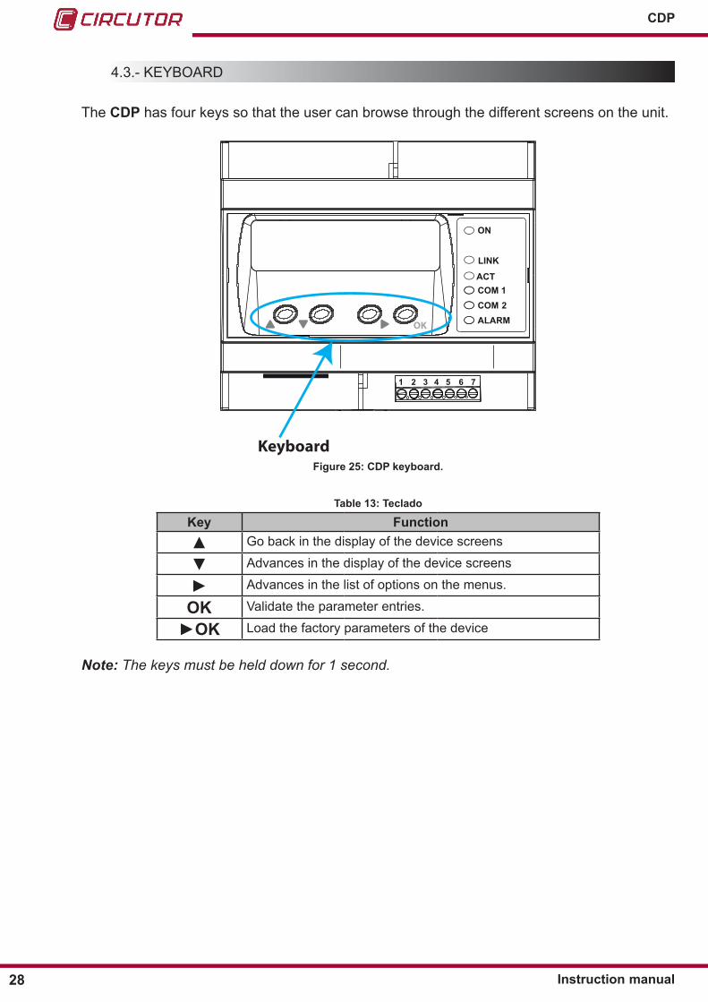
The CDP has four keys so that the user can browse through the different screens on the unit.
ON
ACTCOM 1COM 2ALARMOK
LINK
1 2 3 4 5 6 7
KeyboardFigure 25: CDP keyboard�
Table 13: Teclado
Key Function▲ Go back in the display of the device screens
▼ Advances in the display of the device screens
► Advances in the list of options on the menus.
OK Validate the parameter entries.
►OK Load the factory parameters of the device
Note: The keys must be held down for 1 second.
29Instruction manual
CDP
4.4.- LEDs
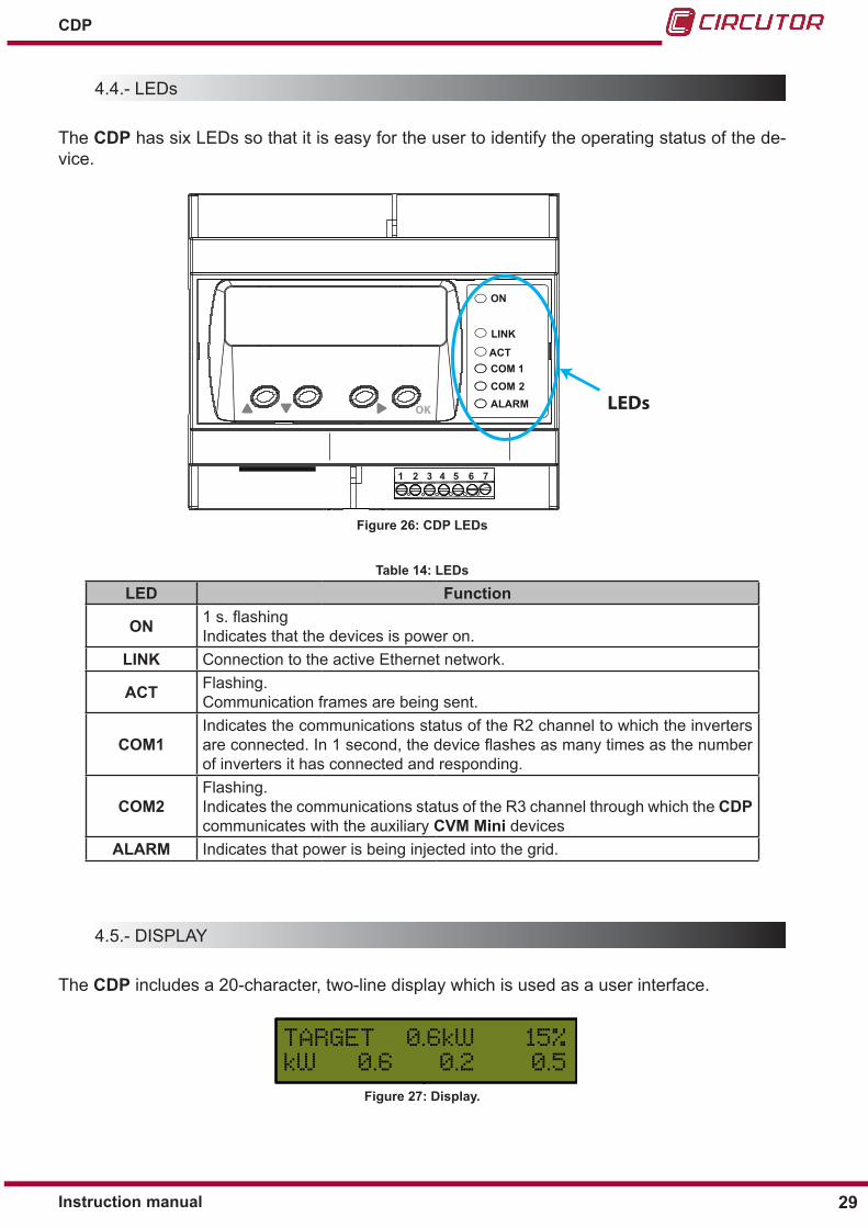
The CDP has six LEDs so that it is easy for the user to identify the operating status of the de-vice.
ON
ACTCOM 1COM 2ALARMOK
LINK
1 2 3 4 5 6 7
LEDs
Figure 26: CDP LEDs
Table 14: LEDs
LED Function
ON 1 s. flashingIndicates that the devices is power on.
LINK Connection to the active Ethernet network.
ACT Flashing.Communication frames are being sent.
COM1Indicates the communications status of the R2 channel to which the inverters are connected. In 1 second, the device flashes as many times as the number of inverters it has connected and responding.
COM2Flashing.Indicates the communications status of the R3 channel through which the CDP communicates with the auxiliary CVM Mini devices
ALARM Indicates that power is being injected into the grid.
4.5.- DISPLAY
The CDP includes a 20-character, two-line display which is used as a user interface.
Figure 27: Display�

30
CDP
Instruction manual
5�- DISPLAY
5.1.- SINGLE-PHASE MODE
Ifthedeviceisconfiguredtoworkinsingle-phasemode,thedefaultscreenisshowninFigure 28.
Power consumed bythe user in kW with 1 decimal.MC3 Channel 1
Power consumed from the grid in kW with 1 decimal.MC3 Channel 2
Power generated bythe inverter in kW with 1 decimal.MC3 Channel 3
Power corresponding to the CDP percentage regulation value
Percentage regulation of the nominal power of the inverter.
Figure 28: Default screen in single-phase mode�
The regulation percentage and corresponding power are indicated on the top line; in the exam-ple shown in the Figure 28 below, the nominal power of the inverter is 4.0 kW and the CDP is sending an order to inject 15%, corresponding to 0.6 kW.
The power consumption for each of the three measuring channels is indicated on the botton line.
If the connection has been performed correctly, the three power values should appear with a positive sign. If any of the values appear with a negative sign, this means that the cable of the phase in question has been connected the other way round and should therefore be turned.
Press the ►keytoaccessthedisplayandconfigurationmenu,Figure 29�
Enter the menu
Enter the menu
Enter the menu
Figure 29: Display and Configuration menu.

31Instruction manual
CDP
5.2.- THREE-PHASE MODE
5�2�1�- BASIC THREE-PHASE CONNECTION
The default screen displayed when the unit has been connected to a basic three-phase system is shown in Figure 30.
---- ----
Power corresponding to the CDP percentage regulation value Percentage regulation of the nominal
power of the inverter.
Total three-phase power consumed by the user, in kW, with one decimal.
Figure 30: Default screen in basic three-phase mode�
Thesameinformationasthesingle-phaseconfigurationisshownonthefirstline.The total three-phase power is shown on the second line.
Press the ►keytoaccessthedisplayandconfigurationmenu,Figure 29�
5�2�2�- THREE-PHASE CONNECTION WITH MONITORING
The default screen displayed when the unit has been connected to a basic three-phase system with monitoring features is shown in Figure 31.
Power consumed bythe user in kW with 1 decimal.MC3 Channel 1
Power consumed from the grid in kW with 1 decimal.MC3 Channel 2
Power generated bythe inverter in kW with 1 decimal.MC3 Channel 3
Power corresponding to the CDP percentage regulation value
Percentage regulation of the nominal power of the inverter.
Figure 31: Default screen in three-phase connection with monitoring�
The top line indicates the percentage three-phase regulation and corresponding power. The bottom line indicates the three-phase power consumption of each one of the measuring channels.
If the connection has been performed correctly, the three power values should appear with a

32
CDP
Instruction manual
positive sign. If any of the values appear with a negative sign, this means that the cable of the phase in question has been connected the other way round and should therefore be turned.
Press the ►keytoaccessthedisplayandconfigurationmenu,Figure 29�
5.3.- DISPLAY MENU : MEASURES
Figure 32 shows the main screen of the Measures menu, displaying all measurement parameters of the device.
Figure 32: Measures menu, main screen�
Pressthe►keytoopenthedisplaymenu.Usethe▼and▲keystobrowsethescreens.Press the OK key to exit the menu.
Table 15: Measures menu�
Measures display menuSingle-phase mode
Voltage and Current to:- User, Channel 1, - Grid, Channel 2, - Inverter, Channel 3
Three-phase mode---- ----
---- ----
Three-phase voltage and current�
Single-phase mode
Inductive reactive power (1)
Capacitive reactive power (1)
From each channel
Three-phase mode----
----
----
----
Three-phase Inductive reactive power (1)
Three-phase Capacitive reactive power (1)
Active energy Consumed (kWh)US : User energy - GR: Grid energy - PV: Inverter energy
Inductive reactive energy consumed (kVArh)US : User energy - GR: Grid energy - PV: Inverter energy

33Instruction manual
CDP
Table 15 (Continuation) : Measures menu�
Measures display menu
Capacitive reactive energy consumed (kVArh)US : User energy - GR: Grid energy - PV: Inverter energy
Active energy generated (kWh)US : User energy - GR: Grid energy - PV: Inverter energy
Inductive reactive energy generated (kVArh)US : User energy - GR: Grid energy - PV: Inverter energy
Capacitive reactive energy generated (kVArh)US : User energy - GR: Grid energy - PV: Inverter energy
(1) A negative sign indicates that the direction of the current is inversed.

34
CDP
Instruction manual
5.4.- DISPLAY WEBSIDE
You can enter the device web site from any browser using the IP address.
https://xxx.xxx.xxx.xxx
Where xxx.xxx.xxx.xxx is the IP address assigned by the user.
Note: Use Google Chrome.Note: When you access the CDP web site for the first time, you will have to accept the security certificate so that you can use secure connections.
Figure 33: Acceptance alert for the SSL secure connection certificate.
The display web site will be different, according to the model of the device.

35Instruction manual
CDP
5�4�1�- CDP-0 MODEL
Power corresponding to the CDP percenta-ge regulation value
Percentage regulation of the nominal power of the inverter
Power consumed by the user
Power generated by the inverter
Power consumed from the grid
Data Logger
Figure 34: Display Webside: CDP-0 model�
Note: When the CDP is configured to operate in the three-phase mode and there is a problem with the exterior CVM minis or these have not been connected, the Power consumed from the grid section will display --
36
CDP
Instruction manual
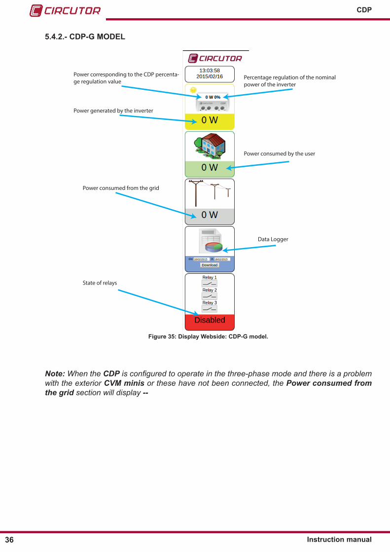
5�4�2�- CDP-G MODEL
Percentage regulation of the nominal power of the inverter
Power corresponding to the CDP percenta-ge regulation value
Power generated by the inverter
Power consumed by the user
Power consumed from the grid
Data Logger
State of relays
Figure 35: Display Webside: CDP-G model�
Note: When the CDP is configured to operate in the three-phase mode and there is a problem with the exterior CVM minis or these have not been connected, the Power consumed from the grid section will display --

37Instruction manual
CDP
5�4�3�- CDP-DUO MODEL
Percentage regulation of the nominal power of the inverter
Power corresponding to the CDP percentage regulation value
Power generated by the inverterPower consumed by the user
Power consumed from the grid (Main)
Data Logger
State of relays
Consumed power of the secondary generator (Secondary).
Parameters Mode 1 (Main)
Parameters Mode 2 (Secondary)
Figure 36: Display Webside: CDP-DUO model�

38
CDP
Instruction manual
5�4�4�- DATA LOGGER
This function allows you to install only the CDPinafirstphase,withouttheinvertersandsolarpanels, so that you can regularly analyse the power consumed and the energy accumulated, in order to analyse the performance of the installation and thus design the future self-consumption installation.
To download the data, the user must select the days between which they want to download the filewiththedatalog.
Figure 37: Selecting the download period�
From, Start date for the download period. The download will start at 00:00. To, End date for the download period. The download will end at 23:59.
On selecting the start or end date a calendar appears which allows you to select the download period, Figure 38. The days marked in green are days with a corresponding log.
Figure 38:Introducing the download start and end date�
Once the start and end date are selected, press the Download logkeyandafilewiththenamecdp�csvwillbedownloadedtothepathconfiguredinthewebbrowser.
Thefileisdownloadedin�cvs format and can be opened in Microsoft Excel. �cvsfilesareasimplefileformattorepresentdataintheformofatable,inwhichthecolumnsareseparatedby commas (or a semicolon in countries which use the comma as the decimal separator: Spain, France, Italy, etc.) and rows are separated by line feeds.
Thefilesizeis100MBytesallowinguserstosaveapproximately5200daysintotal.Themem-ory is of the rotating type; when it is full the oldest value is replaced with the newest one. The size of each log is approximately 200 bytes.If the time is changed and delayed, the existing log is opened as well as the new one.
39Instruction manual
CDP
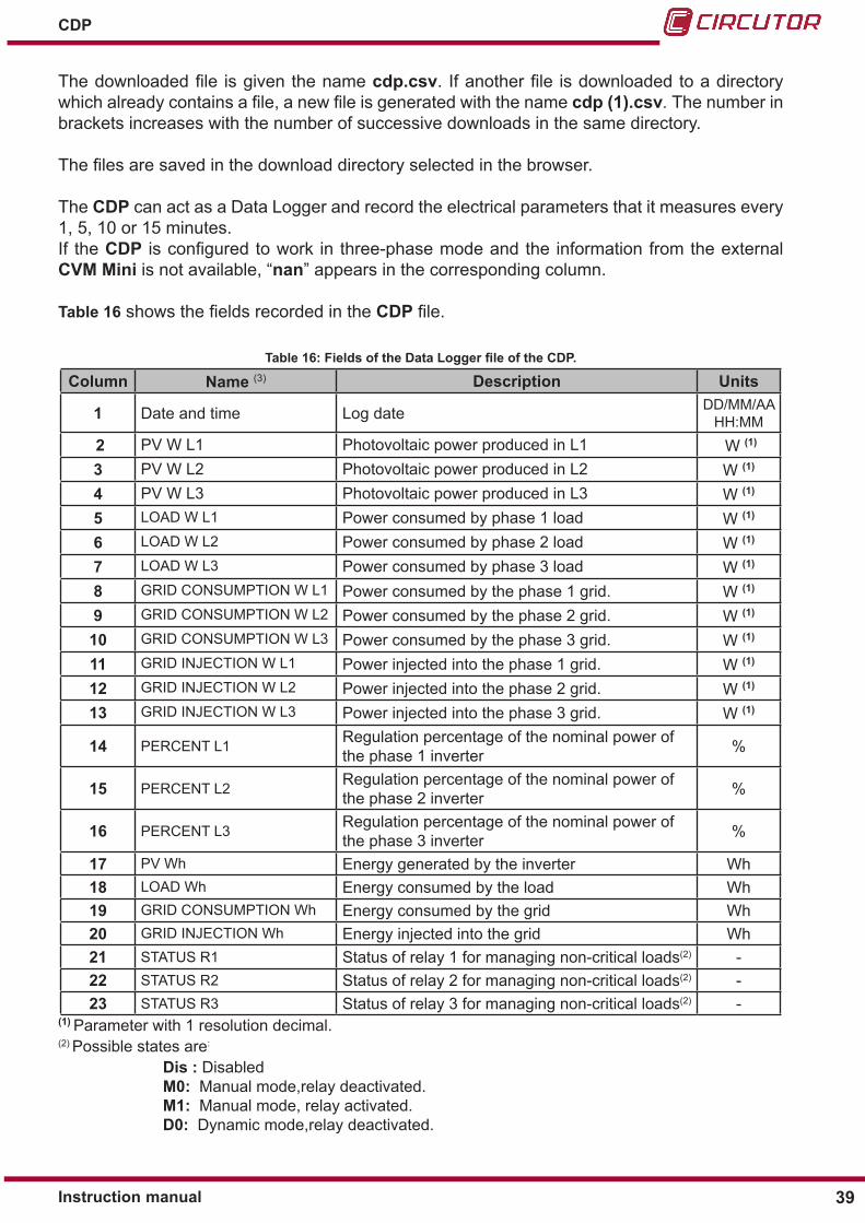
Thedownloadedfile isgiventhenamecdp�csv. Ifanotherfile isdownloadedtoadirectorywhichalreadycontainsafile,anewfileisgeneratedwiththenamecdp (1)�csv. The number in brackets increases with the number of successive downloads in the same directory.
Thefilesaresavedinthedownloaddirectoryselectedinthebrowser.
The CDP can act as a Data Logger and record the electrical parameters that it measures every 1, 5, 10 or 15 minutes.If the CDP isconfiguredtowork in three-phasemodeandthe informationfromtheexternalCVM Mini is not available, “nan” appears in the corresponding column.
Table 16showsthefieldsrecordedintheCDPfile.
Table 16: Fields of the Data Logger file of the CDP.
Column Name (3) Description Units
1 Date and time Log date DD/MM/AA HH:MM
2 PV W L1 Photovoltaic power produced in L1 W (1)
3 PV W L2 Photovoltaic power produced in L2 W (1)
4 PV W L3 Photovoltaic power produced in L3 W (1)
5 LOAD W L1 Power consumed by phase 1 load W (1)
6 LOAD W L2 Power consumed by phase 2 load W (1)
7 LOAD W L3 Power consumed by phase 3 load W (1)
8 GRID CONSUMPTION W L1 Power consumed by the phase 1 grid. W (1)
9 GRID CONSUMPTION W L2 Power consumed by the phase 2 grid. W (1)
10 GRID CONSUMPTION W L3 Power consumed by the phase 3 grid. W (1)
11 GRID INJECTION W L1 Power injected into the phase 1 grid. W (1)
12 GRID INJECTION W L2 Power injected into the phase 2 grid. W (1)
13 GRID INJECTION W L3 Power injected into the phase 3 grid. W (1)
14 PERCENT L1 Regulation percentage of the nominal power of the phase 1 inverter %
15 PERCENT L2 Regulation percentage of the nominal power of the phase 2 inverter %
16 PERCENT L3 Regulation percentage of the nominal power of the phase 3 inverter %
17 PV Wh Energy generated by the inverter Wh18 LOAD Wh Energy consumed by the load Wh19 GRID CONSUMPTION Wh Energy consumed by the grid Wh20 GRID INJECTION Wh Energy injected into the grid Wh21 STATUS R1 Status of relay 1 for managing non-critical loads(2) -22 STATUS R2 Status of relay 2 for managing non-critical loads(2) -23 STATUS R3 Status of relay 3 for managing non-critical loads(2) -
(1) Parameter with 1 resolution decimal.(2) Possible states are:
Dis : Disabled M0: Manual mode,relay deactivated. M1: Manual mode, relay activated. D0: Dynamic mode,relay deactivated.

40
CDP
Instruction manual
D1: Dynamic mode, relay activated.(3)ThesigncriteriaintheDataLoggerfile: Positive power : consumption Negative power : generation
The data gathered by the Data Logger can be used to check the insolation periods of an instal-lation.
Figure 39 shows that during periods in which insolation is minimum, the user’s consumption is taken from the grid, however, it is the inverter that supplies energy during periods with max-imum insolation.
This is the period of maximum insolation during which the energy generated by
the inverter is consumed.
There is no insolation during these periods and energy is obtained from
the grid.Figure 39:Graph showing the operation of the CDP based on insolation�
41Instruction manual
CDP
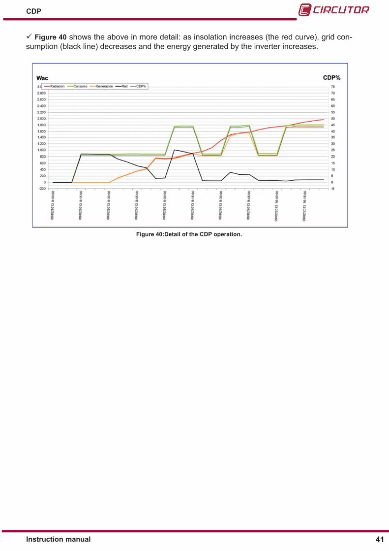
Figure 40 shows the above in more detail: as insolation increases (the red curve), grid con-sumption (black line) decreases and the energy generated by the inverter increases.
Figure 40:Detail of the CDP operation�

42
CDP
Instruction manual
6�- CONFIGURATION
Youcanconfigurethedeviceontheconfigurationwebsite(see“6.3.- CONFIGURATION WEB SITE”).OnlytheIPisconfiguredwiththekeypadintheNetwork menu Figure 41.
Figure 41: Configuration menu: Network
6.1.- CONFIGURATION MENU: NETWORK
Figure 42 shows the main screen of the Network configurationmenu,wheretheEthernetconnectivityparametersareconfigured.
Figure 42: Network configuration menu, main screen.
Press the ►keytoentertheconfigurationmenu.
6�1�1�- DHCP ASSIGNMENT
You can select the DHCP option and configure the IP value in this screen.
●DHCP
Press the ► key to enter edit mode. Usethekeys▲and▼to browse the different options:
Yes, the IP is automatically assigned. No, the TCP parameters are configured manually.

43Instruction manual
CDP
Press the ► key to configure the IP.
●IPNote: If you have set the DHCP option to Yes, the parameter cannot be edited.
Usethekeys▲and▼ to modify the selected digit.Use the key ► to change digit.
Whenyoureachthelastdigit,pressthe►keytoexittheeditmode.
Press the ▼ to go to he next configuration parameter.
Press the OK key, the screen shown in Figure 43, will be displayed, which allows the modifica-tions to be saved and exits the configuration mode.
SAVE CONFNO
Figure 43: Save setup parameters screen�
6�1�2�- NETMASK Y GATEWAY
The Netmask and Gateway are configured in this screen.Note: If you have set the DHCP option to Yes, the parameter cannot be edited.
●MASK
Thissectionconfiguresthe Netmask.Press the ► key to enter edit mode.
Usethekeys▲and▼ to modify the selected digit.Use the key ► to change digit.
Whenyoureachthelastdigit,pressthe►keytoconfiguretheGW.
●GW
ThissectionconfigurestheGateway.
Usethekeys▲and▼ to modify the selected digit.Use the key ► to change digit.
Whenyoureachthelastdigit,pressthe►keytoexittheeditmode.
Press the ▼ to go to he next configuration parameter.
Press the OK key, the screen shown in Figure 43, will be displayed, which allows the modifica-tions to be saved and exits the configuration mode.

44
CDP
Instruction manual
6�1�3�- PRIMARY Y SECONDARY DNS
You can configure the preferred DNS server (DNS1) and alternative DNS server (DNS2) in this screen.Note: If you have set the DHCP option to Yes, the parameter cannot be edited.
●DNS1
ThissectionconfigurestheprimaryDNSserver.Press the ► key to enter edit mode.
Usethekeys▲and▼ to modify the selected digit.Use the key ► to change digit.
Whenyoureachthelastdigit,pressthe►keytoconfiguretheDNS2.
●DNS2
ThissectionconfiguresthesecondaryDNSserver.
Usethekeys▲and▼ to modify the selected digit.Use the key ► to change digit.
Whenyoureachthelastdigit,pressthe►keytoexittheeditmode.
Press the OK key, the screen shown in Figure 43, will be displayed, which allows the modifica-tions to be saved and exits the configuration mode.
6.2.- CONFIGURATION MENU: SYSTEM
Figure 44 shows the main screen of the System configurationmenu,wherethedateofthedeviceareconfigured.
Figure 44: System configuration menu, main screen.
Press the ►keytoentertheconfigurationmenu.
6�2�1�- DATE AND TIME
Youcanalsosetthedateandtimeonthisscreen.Italsodisplaysthefirmwareversion.

45Instruction manual
CDP
Press the ► key to enter edit mode.
Usethekeys▲and▼ to modify the selected digit.Use the key ► to change digit.
Whenyoureachthelastdigit,pressthe►keytoexittheeditmode.
Press the OK key, the screen shown in Figure 43, will be displayed, which allows the modifica-tions to be saved and exits the configuration mode.
6.3.- CONFIGURATION WEBSIDE
You can enter the device web site from any browser using the IP address.
https://xxx.xxx.xxx.xxx/setup/index.html
Where xxx.xxx.xxx.xxx is the IP address assigned by the user.
Note: Use Google Chrome.Note: When you access the CDP web site for the first time, you will have to accept the security certificate so that you can use secure connections.
Figure 45: Acceptance alert for the SSL secure connection certificate.
If you have activated the access password, the unit will request the user name and password on the pop-up screen shown below when you try to access via Web (Figure 46)
Figure 46: Password screen�

46
CDP
Instruction manual
Note : User name: admin
6�3�1�- GENERAL PARAMETERS
The top of the web site shows the device information, Figure 47, and the option to update its firmwareanddate.
Figure 47: Updating parameters
●S/N
Serial number of the device.
●MAC
MAC address of the device.
●Version
This section displays the device version and you can click on the to update the firm-ware of the device.
When pressing button, the screen in Figure 48 appears, where you will need to find the upgrade file that you have downloaded onto the computer and press the Upgrade button.
Note : The upgrade file must be downloaded from the Circutor web site, www.circutor.com
Figure 48: Firmware upgrade screen�

47Instruction manual
CDP
During the upgrade process, you will see the screen in Figure 49.
Figure 49: Screen during the upgrade process�
Note: If the CDP is upgraded with the wrong firmware version for the product, a version error message will appear on the display as shown in Figure 50.
Figure 50: Version error screen�
●Date
This section displays the date and time of the device.
To modify the value, enter the new value and press .
●Config File
When pressing the button, the configuration file is downloaded in .txt format.
●Data Logger
It is possible to reset the historical data stored in the data logger by pressing the button.
6�3�2�- POWER CONTROL & DATA LOGGER : INVERTER
Youcanconfiguretheinverter’sparametersinthissection,Figure 51.
Figure 51: Inverter setup parameters�
●Inverter type
InthissectionitisconfiguredInvertermodeltobeusedintheinstallation.Note: All inverters connected to the CDP must be of the same type.

48
CDP
Instruction manual
If you select the option “Generic 4 inputs”, the parameter Mode appears on the screen with two possible options (Figure 52):
●Discrete: this option allows 4 regulation stages: 0%, 30%, 60% and 100%.●Binary: this option allows 16 regulation stages between 0% and 100% of the inverter’s nominal power. The relay combinations are done using binary logic.
When the Binary option is activated, relay number 4 stops functioning as a pro-tection against reverse current and starts functioning like the rest of the relays.
Figure 52: Inverter setup parameters (Type : Generic 4 inputs)
If the “SMA” option is selected, the Inverter x S/N parameters will appers on the screen, Figure 53, where you will need to enter the serial numbers of each of the inverters.
Figure 53:Inverter setup parameters (Type : SNA)
Note : It is important to enter the serial number of each inverter in the phase in which it was installed, so that the CDP can detect it.
●Inverter power
InthissectionitisconfiguredthetotalpowertobecontrolledbytheCDP, in W.
Note: If more than 1 inverter is controlled, enter the sum of the power controlled by each invert-er in this section.
Maximum value : 1MW
●Number of inverter
Inthissectionitisconfiguredthenumberofinverterstocontrol.
49Instruction manual
CDP
6�3�3�- POWER CONTROL & DATA LOGGER : CONTROL
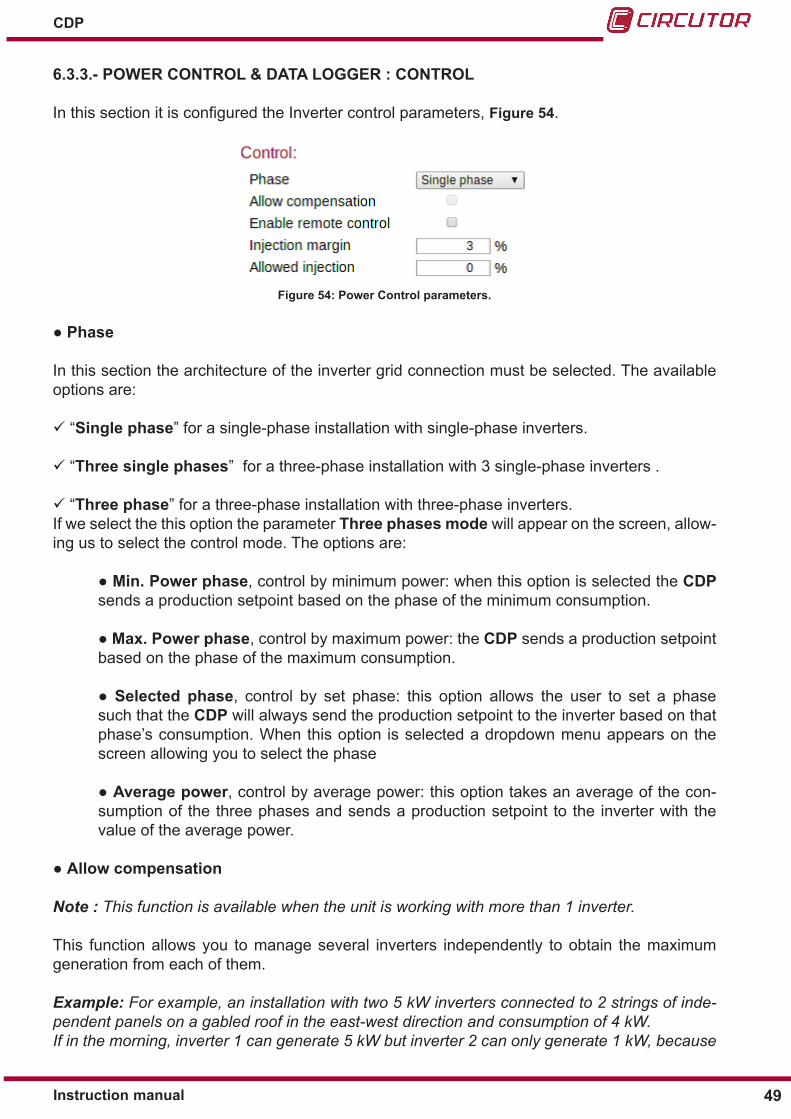
InthissectionitisconfiguredtheInvertercontrolparameters,Figure 54.
Figure 54: Power Control parameters�
●Phase
In this section the architecture of the inverter grid connection must be selected. The available options are:
“Single phase” for a single-phase installation with single-phase inverters.
“Three single phases” for a three-phase installation with 3 single-phase inverters .
“Three phase” for a three-phase installation with three-phase inverters.If we select the this option the parameter Three phases mode will appear on the screen, allow-ing us to select the control mode. The options are:
●Min� Power phase, control by minimum power: when this option is selected the CDP sends a production setpoint based on the phase of the minimum consumption.
●Max. Power phase, control by maximum power: the CDP sends a production setpoint based on the phase of the maximum consumption.
●Selected phase, control by set phase: this option allows the user to set a phase such that the CDP will always send the production setpoint to the inverter based on that phase’s consumption. When this option is selected a dropdown menu appears on the screen allowing you to select the phase
●Average power, control by average power: this option takes an average of the con-sumption of the three phases and sends a production setpoint to the inverter with the value of the average power.
●Allow compensation
Note : This function is available when the unit is working with more than 1 inverter.
This function allows you to manage several inverters independently to obtain the maximum generation from each of them.
Example: For example, an installation with two 5 kW inverters connected to 2 strings of inde-pendent panels on a gabled roof in the east-west direction and consumption of 4 kW.If in the morning, inverter 1 can generate 5 kW but inverter 2 can only generate 1 kW, because
50
CDP
Instruction manual
the panels are not receiving sufficient radiation, rather than requesting 2 kW from each inverter, the CDP will request the maximum power from the inverter that generates the least (1 kW) and the remainder will be requested from the inverter which generates more (3 kW), to try to reach the required consumption.To do this, it will gradually increase the regulation percentage of both inverters at the same time until both generate a total power equivalent to that required by the load.
Note: In three-phase systems, the connection of a CVM Mini is mandatory to measure the power consumed/delivered to the mains.
●Enable remote control
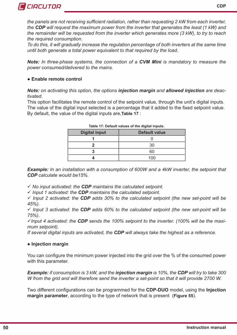
Note: on activating this option, the options injection margin and allowed injection are deac-tivated.This option facilitates the remote control of the setpoint value, through the unit’s digital inputs.Thevalueofthedigitalinputselectedisapercentagethatitaddedtothefixedsetpointvalue.By default, the value of the digital inputs are,Table 17 :
Table 17: Default values of the digital inputs�
Digital input Default value1 02 303 604 100
Example: In an installation with a consumption of 600W and a 4kW inverter, the setpoint that CDP calculate would be15%.
No input activated: the CDP maintains the calculated setpoint. Input 1 activated: the CDP maintains the calculated setpoint. Input 2 activated: the CDP adds 30% to the calculated setpoint (the new set-point will be 45%). Input 3 activated: the CDP adds 60% to the calculated setpoint (the new set-point will be 75%).Input 4 activated: the CDP sends the 100% setpoint to the inverter. (100% will be the maxi-mum setpoint).If several digital inputs are activated, the CDP will always take the highest as a reference.
●Injection margin
Youcanconfiguretheminimumpowerinjectedintothegridoverthe%oftheconsumedpowerwith this parameter.
Example: if consumption is 3 kW, and the injection margin is 10%, the CDP will try to take 300 W from the grid and will therefore send the inverter a set-point so that it will provide 2700 W.
TwodifferentconfigurationscanbeprogrammedfortheCDP-DUO model, using the Injection margin parameter, according to the type of network that is present (Figure 55).

51Instruction manual
CDP
Figure 55: Power Control parameters (CDP-DUO)
When the device has no active digital inputs, the CDP-DUO operates with the injection para-meters of Mode 1 (Main).
If you activate digital input 1 (terminal no. 28 in Tabla 3), the unit will operate with the injection parametersconfiguredinMode2(Secondary).
●Allowed injection
InthissectionitisconfiguredthePercentageofinjectioninexcessoftheconsumedpower.This value can be positive or negative with respect to the photovoltaic power.
The negative values are used for hybrid networks, renewable and non-renewable networks (UPS, generator set, grid, etc.), where it is important that the non-renewable network is not permanently connecting and disconnecting. A negative Allowed injection forces the non-re-newable energy source to constantly supply a residual percentage of the consumption.
Example: For example, an installation with one 5 kW inverter and a 100 kW generator set.Consumption is 4 kW and one of the loads needs to be permanently supplied.In this case, the variable Inverter power will be programmed to 5000 W and the variable Allowed injection to a value of -1%. Therefore, the generator set will always be connected, supplying 50 W.
TwodifferentconfigurationscanbeprogrammedfortheCDP-DUO model, using the Allowed injection, according to the type of network that is present (Figure 55).
When the device has no active digital inputs, the CDP-DUO operates with the injection para-meters of Mode 1 (Main).
If you activate digital input 1 (terminal no. 28 in Tabla 3), the unit will operate with the injection parametersconfiguredinMode2(Secondary).
●Enabled Power Factor (CDP-DUO Model)
When you activate this option, the CDP-DUO sends setpoints to compensate the reactive ener-gy being consumed. This function is only available with FRONIUS inverters and the FRONIUS MB communications protocol.
●Force Secondary Mode (CDP-DUO Model)
If you activate this option, the CDP-DUOwillalwaysoperatewiththeparametersconfiguredinthe Secondary sector.

52
CDP
Instruction manual
6�3�4�- POWER CONTROL & DATA LOGGER : REVERSE CURRENT RELAY
Inthissectionit isconfiguredtheparametersfortheinversecurrentcontrolrelay,Figure 56. (See “4.1.2.- GRID INJECTION PROTECTION RELAY”)
Figure 56: Reverse current relay parameters�
●Enable reverse current relay
Enable this option to activate the reverse current relay protection. If the device measures a neg-ative power value in the grid, it desactivates the inverse current relay to disconnect the inverter.This relay acts as redundant protection against a possible grid injection.The relay has 3 terminals and can be NO or NC, depending on how it is connected.
In three-phase mode it is essential to install a CVM Mini to measure the grid.
●Stop time
This parameter configures the time during which the grid injection condition must remain active before activating the inverse current relay (seconds).
●Reconnection Time
This parameter configures the time the device waits before deactivating relay no. 4 (seconds) when it stops measuring the inverse current.
●Max disconnections
This parameter configures the number of disconnections the CDP can perform via the inverse current before it is definitively locked.●Disconnect� timeout
This parameter configures the time once the maximum number of reconnections has been reached, this is the time taken for the unit to secure the inverse current relay. This value must be equal to or higher than:
Disconnect. Timeout > = ( Stop time+ Reconnection time) x (Max.Disconnections).

53Instruction manual
CDP
6�3�5�- POWER CONTROL & DATA LOGGER : AUXILIAR LOADS RELAYS
Youcanconfiguretheoptionalmanagementofnon-criticalloadsinthissection,Figure 57. (See “4.1.3.- CDP-G MODEL: NON-CRITICAL LOAD MANAGEMENT”)
Figure 57: Auxiliar loads relays parameters.
●Load Management Mode
This parameter is used to select how non-critical loads are managed. The possible options are:
“Disabled”, they are not managed.
“Manual”, relays are managed manually� . If you select the “Manual”, option, the 3 relays appear on the screen, , click on the button of each relay to activate or deactivate them manually.
Figure 58: Load Management Mode: Manual�
“Dynamic”, If you select dynamic management of the loads, you have to program the follow-ing parameters, Figure 59:
Figure 59: Load Management Mode: Dynamic� ●Max Modulation value
In this parameter you enter the maximum modulation value and can add dynamic loads to the system below.
●Connection Order Select how you are going to connect the relays: “Priority” or “Rotating”

54
CDP
Instruction manual
●1st Priority, 2nd Priority, 3rd PriorityIf you have selected priority connection, you will then select the priority for each of the relays.
●Max grid contributionIn this section you enter the value for maximum grid contribution, which is the minimum value for deactivating loads.
●Reconnecting timeMinimum time to allow system stabilisation between: the activation of two loads. the deactivation of two loads. the deactivation of the last load and the activation of a new one.
●Relay 1, Relay 2, Relay 3: Power This parameter configures the power to be consumed by the load. If it is zero, the load is considered to be deactivated.
●Relay 1, Relay 2, Relay 3: Min Connection TimeThis parameter configures the minimum time that a load must stay connected before it can be deactivated, if required.
6�3�6�- POWER CONTROL & DATA LOGGER : DATA LOGGER
This parameter configures the time to record logs in the Data Logger, Figure 60. (See “5.4.4.- DATA LOGGER”)
Figure 60: Data Logger parameters�
●Time between registers
This parameter configures the time to record logs in the Data Logger. The possible values are: 1, 5, 10, 15 or 60 minutes.
6�3�7�- ANALYZERS SETUP : LOAD ANALYZER
Inthissectionit isalsopossibletoconfigurethecommunicationsbetweentheCDP and the power analyzers Figure 61.
Figure 61: Parámetros de configuración de los Analizadores

55Instruction manual
CDP
●Enable external analyzer
When you enable this option, an external analyser is enabled as the measuring device, instead of the CDP.
●Primary current
Usethisparametertoconfigurethevalueoftheprimaryoftheloadanalyser’scurrenttrans-former.
●Device number
Enter the peripheral number of the external analyser in this parameter, if the corresponding option has been activated Enable external analyzer.
6�3�8�- ANALYZERS SETUP : GRID ANALYZER
YoucanconfigurethecommunicationsbetweentheCDP and network analyser in this section, Figura 49.
●Primary current
Usethisparametertoconfigurethevalueoftheprimaryofthenetworkanalyser’scurrenttrans-former.
●Device number
This parameter configures the peripheral number of the CVM power analyzer installed to meas-ure the consumption of the grid.
6�3�9�- ANALYZERS SETUP : PV ANALYZER
YoucanconfigurethecommunicationsbetweentheCDP and a photovoltaic energy production analyser, Figura 49.
●Enable external analyzer
When you enable this option, an external analyser is used as the measuring unit, instead of the CDP.The CDP automatically calculates the values of the photovoltaic production using the consump-tion measurements (Load analyzer) and the grid (Grid analyzer).Therefore, enabling this option is only of interest in installations which already have a CVM power analyzer installed, which is not communicating with any system (software or automaton) and the user wants the CDP to read the values measured by this analyzer.
●Primary current
UsethisparametertoconfigurethevalueoftheprimaryofthePVanalyser’scurrenttransform-er.

56
CDP
Instruction manual
●Device number
Enter the peripheral number of the external analyser in this parameter, if the corresponding option has been activated Enable external analyzer.
6�3�10�- ANALYZERS SETUP : COMUNICATIONS
ThissectioncanbeusedtoconfigurethetransmissionspeedoftheRS-485 bus.
Figure 62: Analyser setup parameters: Baudrate
●Baudrate
UsethisparametertoconfigurethetransmissionspeedoftheRS-485 bus.
6�3�11�- NETWORK & SECURITY SETUP : NETWORK
YoucanconfigurethenetworkparametersoftheCDP in this section, Figure 63.
Figure 63: Network setup parameters�
●Host name
To select the assignment of a static IP (DHCP = Off), enter in this section the MAC address shown on the label attached to the side of the unit, which appears as 00:26:45:XX:XX:XX
●DHCP
SelecttheconfigurationoftheIPaddressofthedeviceinthissection:
DHCP = On,automaticconfiguration. DHCP = Off,manualconfiguration.
57Instruction manual
CDP
●AddressNote: If you have set the DHCP option to On, the parameter cannot be edited.
This parameter configures the IP address.
●NetmaskNote: If you have set the DHCP option to On, the parameter cannot be edited.
This parameter configures the Netmask.
●GatewayNote: If you have set the DHCP option to On, the parameter cannot be edited.
This parameter configures the gateway.
●Primary DNS serverNote: If you have set the DHCP option to On, the parameter cannot be edited.
This parameter configures the primary DNS server.
●Secondary DNS serverNote: If you have set the DHCP option to On, the parameter cannot be edited.
This parameter configures the secondary DNS server.
6�3�12�- NETWORK & SECURITY SETUP : SECURITY
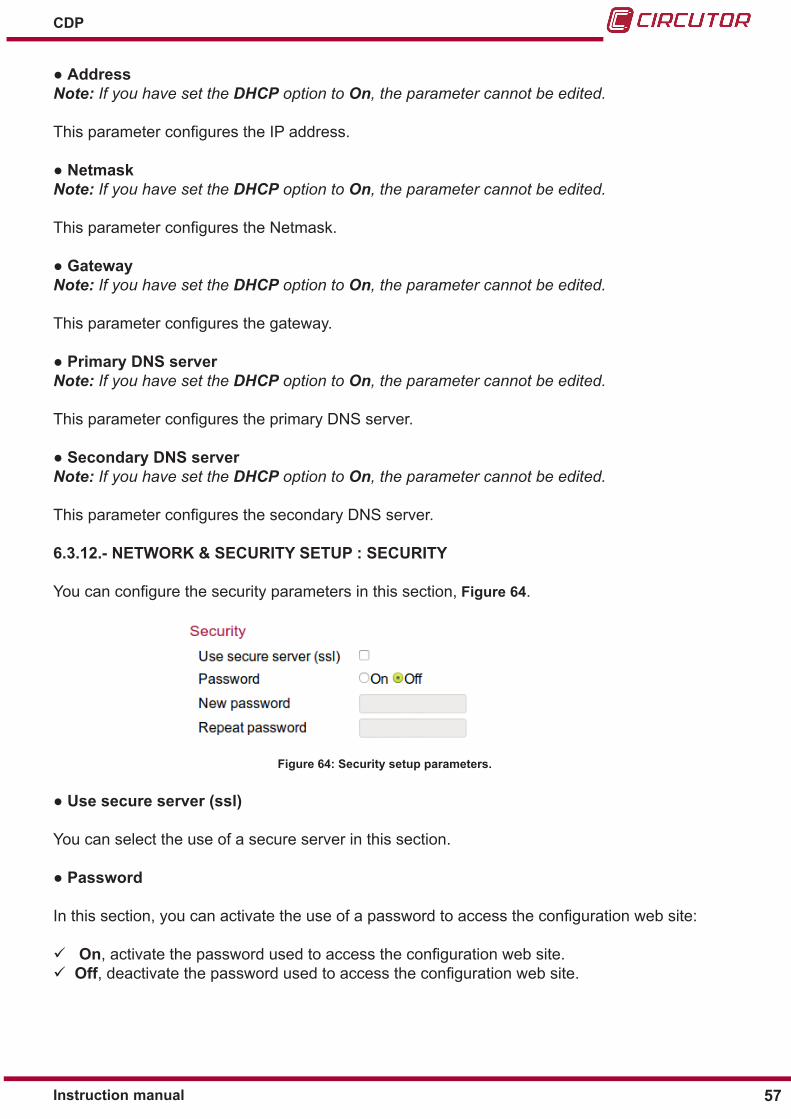
Youcanconfigurethesecurityparametersinthissection, Figure 64.
Figure 64: Security setup parameters�
●Use secure server (ssl)
You can select the use of a secure server in this section.
●Password
Inthissection,youcanactivatetheuseofapasswordtoaccesstheconfigurationwebsite:
On,activatethepasswordusedtoaccesstheconfigurationwebsite. Off,deactivatethepasswordusedtoaccesstheconfigurationwebsite.

58
CDP
Instruction manual
●New password
Enter the new password in this parameter.
●Repeat password
Enter new password again in this parameter.
6�3�13�- SAVE SETUP, LOAD DEFAULT SETUP y RESET CDP
Thereare3buttonsatthebottomoftheconfigurationwebsite,Figure 65�
Figure 65: Save setup, Load default setup and Reset CDP buttons�
● Pressthesaveconfigurationbuttonafterconfiguringthedevice.
● When selecting this button, the devices loads the default values.
● When selecting this button, the CDP is reset.

59Instruction manual
CDP
7�- CDP-G MODEL : OPERATING EXAMPLES
7.1.- SINGLE-PHASE INSTALLATION WITH 1 LOAD TO BE CONNECTED
We start with a single-phase installation in which we want to use the excess photovoltaic pro-duction to supply 1 non-critical load, such as a heat pump.
Load 1: 5000 W heat pump
The goal is to activate these loads during times in which there is a production excess, thus re-ducing energy costs.
This is the start data:Table 18:Start data
Phase Inverterpower Consumption Setpoint Current production
L1 10000 W 4000 W 40% 4000 W (40% of the nominal)
CDP
4000 W
4000 W
0 W
40%
Loads4000 W
Load 15000 W
Relay 1
Figure 66:Single-phase installation with 1 load to connect: Start mode�
The CDP-G programming is shown in Table 19�
Table 19:CDP-G programming�
Parameter ValueInverter : Inverter power 10000 WInverter : Number of inverter 1Control : Phase Single phaseControl : Injection margin 0 %Auxiliar Loads Relays: Load Management Mode DynamicAuxiliar Loads Relays: Max modulation value 90 %Auxiliar Loads Relays: Max grid contribution 20 %

60
CDP
Instruction manual
Table 19 (Continuation): CDP-G programming�Parameter ValueAuxiliar Loads Relays: Reconnecting time 5 minutesRelay 1: Power 5000 WRelay 1: Min connection time 90 minutes
The CDP-G can connect Load 1 if 2 conditions are met, according to the programmed values:
Condition 1 :
𝑃𝑃𝑃𝑃𝑃𝑃𝑃𝑃𝑃𝑃𝑃𝑃𝑃𝑃𝑃𝑃𝑃𝑃𝑃𝑃𝑃𝑃𝑃𝑃𝑃𝑃𝑃𝑃𝑃𝑃𝑃𝑃𝑃𝑃 𝑃𝑃𝑃𝑃𝑖𝑖𝑃𝑃𝑖𝑖𝑖𝑖𝑃𝑃𝑖𝑖
𝑥𝑥100 ≤ 𝑀𝑀𝑃𝑃𝑥𝑥.𝑃𝑃𝑃𝑃𝑃𝑃𝑃𝑃𝑃𝑃𝑃𝑃𝑖𝑖𝑃𝑃𝑃𝑃𝑃𝑃 𝑖𝑖𝑃𝑃𝑃𝑃𝑃𝑃𝑃𝑃
𝑃𝑃𝑐𝑐𝑐𝑐𝑐𝑐𝑐𝑐𝑐𝑐𝑐𝑐𝑐𝑐𝑐𝑐𝑃𝑃𝑐𝑐𝑚𝑚𝑚𝑚𝑚𝑚𝑉𝑉
⋅ 100
𝑃𝑃Grid
∑𝑃𝑃CG· 100
𝑃𝑃𝑃𝑃𝑃𝑃𝑃𝑃𝑃𝑃𝑃𝑃𝑃𝑃𝑃𝑃𝑃𝑃𝑃𝑃𝑃𝑃𝑃𝑃𝑃𝑃𝑃𝑃𝑃𝑃𝑃𝑃𝑃𝑃 𝑃𝑃𝑃𝑃𝑖𝑖𝑃𝑃𝑖𝑖𝑖𝑖𝑃𝑃𝑖𝑖
𝑥𝑥100 ≤ 𝑀𝑀𝑃𝑃𝑥𝑥.𝑀𝑀𝑃𝑃𝑃𝑃𝑃𝑃𝑃𝑃𝑃𝑃𝑖𝑖𝑃𝑃𝑃𝑃𝑃𝑃 𝑉𝑉𝑃𝑃𝑃𝑃𝑃𝑃𝑃𝑃
( 400010000
𝑥𝑥100 = 40%) 40% ≤ 90% This condition is met
𝑷𝑷𝒈𝒈𝒈𝒈𝒈𝒈𝒈𝒈∑𝑷𝑷𝒄𝒄𝒄𝒄𝒄𝒄𝒄𝒄𝒄𝒄𝒄𝒄𝒄𝒄𝒄𝒄𝒈𝒈 𝒈𝒈𝒄𝒄𝒓𝒓𝒓𝒓𝒓𝒓𝒓𝒓
< 𝑀𝑀𝒓𝒓𝒂𝒂 𝑮𝑮𝒈𝒈𝒈𝒈𝒈𝒈 𝒄𝒄𝒄𝒄𝒄𝒄𝒄𝒄𝒈𝒈𝒈𝒈𝒄𝒄𝒄𝒄𝒄𝒄𝒈𝒈𝒄𝒄𝒄𝒄
( 30005000
= 60%) 60% ≤ 20% This condition is not met
( 06000
= 0%) 0% ≤ 50% This condition is met
( 600010000
𝑥𝑥100 = 60%) 60% ≤ 90% This condition is met
( 08000
= 0%) 0% ≤ 50% This condition is met
( 800010000
𝑥𝑥100 = 80%) 80% ≤ 90% This condition is met
( 100010000
= 10%) 10% ≤ 50% This condition is met
The programmed Max modulation value has been set to 90%, i.e., when the consumed power / Inverter power ratio drops below 90%, the CDP-G will try to connect the associated loads.
In this case:
𝑃𝑃𝑃𝑃𝑃𝑃𝑃𝑃𝑃𝑃𝑃𝑃𝑃𝑃𝑃𝑃𝑃𝑃𝑃𝑃𝑃𝑃𝑃𝑃𝑃𝑃𝑃𝑃𝑃𝑃𝑃𝑃𝑃𝑃 𝑃𝑃𝑃𝑃𝑖𝑖𝑃𝑃𝑖𝑖𝑖𝑖𝑃𝑃𝑖𝑖
𝑥𝑥100 ≤ 𝑀𝑀𝑃𝑃𝑥𝑥.𝑃𝑃𝑃𝑃𝑃𝑃𝑃𝑃𝑃𝑃𝑃𝑃𝑖𝑖𝑃𝑃𝑃𝑃𝑃𝑃 𝑖𝑖𝑃𝑃𝑃𝑃𝑃𝑃𝑃𝑃
𝑃𝑃𝑐𝑐𝑐𝑐𝑐𝑐𝑐𝑐𝑐𝑐𝑐𝑐𝑐𝑐𝑐𝑐𝑃𝑃𝑐𝑐𝑚𝑚𝑚𝑚𝑚𝑚𝑉𝑉
⋅ 100
𝑃𝑃Grid
∑𝑃𝑃CG· 100
𝑃𝑃𝑃𝑃𝑃𝑃𝑃𝑃𝑃𝑃𝑃𝑃𝑃𝑃𝑃𝑃𝑃𝑃𝑃𝑃𝑃𝑃𝑃𝑃𝑃𝑃𝑃𝑃𝑃𝑃𝑃𝑃𝑃𝑃 𝑃𝑃𝑃𝑃𝑖𝑖𝑃𝑃𝑖𝑖𝑖𝑖𝑃𝑃𝑖𝑖
𝑥𝑥100 ≤ 𝑀𝑀𝑃𝑃𝑥𝑥.𝑀𝑀𝑃𝑃𝑃𝑃𝑃𝑃𝑃𝑃𝑃𝑃𝑖𝑖𝑃𝑃𝑃𝑃𝑃𝑃 𝑉𝑉𝑃𝑃𝑃𝑃𝑃𝑃𝑃𝑃
( 400010000
𝑥𝑥100 = 40%) 40% ≤ 90% This condition is met
𝑷𝑷𝒈𝒈𝒈𝒈𝒈𝒈𝒈𝒈∑𝑷𝑷𝒄𝒄𝒄𝒄𝒄𝒄𝒄𝒄𝒄𝒄𝒄𝒄𝒄𝒄𝒄𝒄𝒈𝒈 𝒈𝒈𝒄𝒄𝒓𝒓𝒓𝒓𝒓𝒓𝒓𝒓
< 𝑀𝑀𝒓𝒓𝒂𝒂 𝑮𝑮𝒈𝒈𝒈𝒈𝒈𝒈 𝒄𝒄𝒄𝒄𝒄𝒄𝒄𝒄𝒈𝒈𝒈𝒈𝒄𝒄𝒄𝒄𝒄𝒄𝒈𝒈𝒄𝒄𝒄𝒄
( 30005000
= 60%) 60% ≤ 20% This condition is not met
( 06000
= 0%) 0% ≤ 50% This condition is met
( 600010000
𝑥𝑥100 = 60%) 60% ≤ 90% This condition is met
( 08000
= 0%) 0% ≤ 50% This condition is met
( 800010000
𝑥𝑥100 = 80%) 80% ≤ 90% This condition is met
( 100010000
= 10%) 10% ≤ 50% This condition is met
Condition 2 :
If Injection margin = 0% Grid Power < 3 x 0.03 x Consumed Power
If Injection margin ≠ 0% Grid Power < 3 x Injection margin x Consumed Power
In this case: 0 < 3 x 0.03 x 4000 → this condition is med
Condition 1 Condition 2 Action
Relay 1 is closed and Load 1 is connected (Figure 67)�

61Instruction manual
CDP
CDP
6000 W
4000 W
3000 W
90%
5000 W
Loads4000 W
Load 15000 W
Relay 1
Figure 67:Single-phase installation with 1 load to connect: Load 1 connected�
In this situation the CDP-G maintains the system without adding or removing any loads for a timeequallingthelongeroftheconfiguredReconnection time and Min� disconnection time variables, in order to achieve system stability (in this case 90 minutes).
To check if the Load 1 must be disconnected, the CDP-G waits for the amount of time pro-grammed in the Min� connection time variable and then checks if the following condition is met:
Condition 3 :
𝑃𝑃𝑃𝑃𝑃𝑃𝑃𝑃𝑃𝑃𝑃𝑃𝑃𝑃𝑃𝑃𝑃𝑃𝑃𝑃𝑃𝑃𝑃𝑃𝑃𝑃𝑃𝑃𝑃𝑃𝑃𝑃𝑃𝑃 𝑃𝑃𝑃𝑃𝑖𝑖𝑃𝑃𝑖𝑖𝑖𝑖𝑃𝑃𝑖𝑖
𝑥𝑥100 ≤ 𝑀𝑀𝑃𝑃𝑥𝑥.𝑃𝑃𝑃𝑃𝑃𝑃𝑃𝑃𝑃𝑃𝑃𝑃𝑖𝑖𝑃𝑃𝑃𝑃𝑃𝑃 𝑖𝑖𝑃𝑃𝑃𝑃𝑃𝑃𝑃𝑃
𝑃𝑃𝑐𝑐𝑐𝑐𝑐𝑐𝑐𝑐𝑐𝑐𝑐𝑐𝑐𝑐𝑐𝑐𝑃𝑃𝑐𝑐𝑚𝑚𝑚𝑚𝑚𝑚𝑉𝑉
⋅ 100
𝑃𝑃Grid
∑𝑃𝑃CG· 100
𝑃𝑃𝑃𝑃𝑃𝑃𝑃𝑃𝑃𝑃𝑃𝑃𝑃𝑃𝑃𝑃𝑃𝑃𝑃𝑃𝑃𝑃𝑃𝑃𝑃𝑃𝑃𝑃𝑃𝑃𝑃𝑃𝑃𝑃 𝑃𝑃𝑃𝑃𝑖𝑖𝑃𝑃𝑖𝑖𝑖𝑖𝑃𝑃𝑖𝑖
𝑥𝑥100 ≤ 𝑀𝑀𝑃𝑃𝑥𝑥.𝑀𝑀𝑃𝑃𝑃𝑃𝑃𝑃𝑃𝑃𝑃𝑃𝑖𝑖𝑃𝑃𝑃𝑃𝑃𝑃 𝑉𝑉𝑃𝑃𝑃𝑃𝑃𝑃𝑃𝑃
( 400010000
𝑥𝑥100 = 40%) 40% ≤ 90% This condition is met
𝑷𝑷𝒈𝒈𝒈𝒈𝒈𝒈𝒈𝒈∑𝑷𝑷𝒄𝒄𝒄𝒄𝒄𝒄𝒄𝒄𝒄𝒄𝒄𝒄𝒄𝒄𝒄𝒄𝒈𝒈 𝒈𝒈𝒄𝒄𝒓𝒓𝒓𝒓𝒓𝒓𝒓𝒓
< 𝑀𝑀𝒓𝒓𝒂𝒂 𝑮𝑮𝒈𝒈𝒈𝒈𝒈𝒈 𝒄𝒄𝒄𝒄𝒄𝒄𝒄𝒄𝒈𝒈𝒈𝒈𝒄𝒄𝒄𝒄𝒄𝒄𝒈𝒈𝒄𝒄𝒄𝒄
( 30005000
= 60%) 60% ≤ 20% This condition is not met
( 06000
= 0%) 0% ≤ 50% This condition is met
( 600010000
𝑥𝑥100 = 60%) 60% ≤ 90% This condition is met
( 08000
= 0%) 0% ≤ 50% This condition is met
( 800010000
𝑥𝑥100 = 80%) 80% ≤ 90% This condition is met
( 100010000
= 10%) 10% ≤ 50% This condition is met
𝑃𝑃𝑃𝑃𝑃𝑃𝑃𝑃𝑃𝑃𝑃𝑃𝑃𝑃𝑃𝑃𝑃𝑃𝑃𝑃𝑃𝑃𝑃𝑃𝑃𝑃𝑃𝑃𝑃𝑃𝑃𝑃𝑃𝑃 𝑃𝑃𝑃𝑃𝑖𝑖𝑃𝑃𝑖𝑖𝑖𝑖𝑃𝑃𝑖𝑖
𝑥𝑥100 ≤ 𝑀𝑀𝑃𝑃𝑥𝑥.𝑃𝑃𝑃𝑃𝑃𝑃𝑃𝑃𝑃𝑃𝑃𝑃𝑖𝑖𝑃𝑃𝑃𝑃𝑃𝑃 𝑖𝑖𝑃𝑃𝑃𝑃𝑃𝑃𝑃𝑃
𝑃𝑃𝑐𝑐𝑐𝑐𝑐𝑐𝑐𝑐𝑐𝑐𝑐𝑐𝑐𝑐𝑐𝑐𝑃𝑃𝑐𝑐𝑚𝑚𝑚𝑚𝑚𝑚𝑉𝑉
⋅ 100
𝑃𝑃Grid
∑𝑃𝑃CG· 100
𝑃𝑃𝑃𝑃𝑃𝑃𝑃𝑃𝑃𝑃𝑃𝑃𝑃𝑃𝑃𝑃𝑃𝑃𝑃𝑃𝑃𝑃𝑃𝑃𝑃𝑃𝑃𝑃𝑃𝑃𝑃𝑃𝑃𝑃 𝑃𝑃𝑃𝑃𝑖𝑖𝑃𝑃𝑖𝑖𝑖𝑖𝑃𝑃𝑖𝑖
𝑥𝑥100 ≤ 𝑀𝑀𝑃𝑃𝑥𝑥.𝑀𝑀𝑃𝑃𝑃𝑃𝑃𝑃𝑃𝑃𝑃𝑃𝑖𝑖𝑃𝑃𝑃𝑃𝑃𝑃 𝑉𝑉𝑃𝑃𝑃𝑃𝑃𝑃𝑃𝑃
( 400010000
𝑥𝑥100 = 40%) 40% ≤ 90% This condition is met
𝑷𝑷𝒈𝒈𝒈𝒈𝒈𝒈𝒈𝒈∑𝑷𝑷𝒄𝒄𝒄𝒄𝒄𝒄𝒄𝒄𝒄𝒄𝒄𝒄𝒄𝒄𝒄𝒄𝒈𝒈 𝒈𝒈𝒄𝒄𝒓𝒓𝒓𝒓𝒓𝒓𝒓𝒓
< 𝑀𝑀𝒓𝒓𝒂𝒂 𝑮𝑮𝒈𝒈𝒈𝒈𝒈𝒈 𝒄𝒄𝒄𝒄𝒄𝒄𝒄𝒄𝒈𝒈𝒈𝒈𝒄𝒄𝒄𝒄𝒄𝒄𝒈𝒈𝒄𝒄𝒄𝒄
( 30005000
= 60%) 60% ≤ 20% This condition is not met
( 06000
= 0%) 0% ≤ 50% This condition is met
( 600010000
𝑥𝑥100 = 60%) 60% ≤ 90% This condition is met
( 08000
= 0%) 0% ≤ 50% This condition is met
( 800010000
𝑥𝑥100 = 80%) 80% ≤ 90% This condition is met
( 100010000
= 10%) 10% ≤ 50% This condition is met
Condition 3 Action
Relay 1 is open and Load 1 is disconnected.
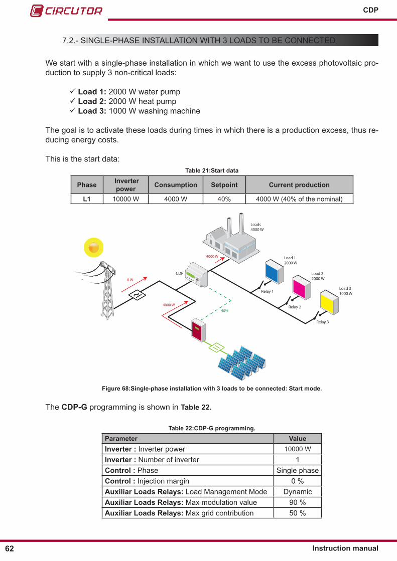
62
CDP
Instruction manual
7.2.- SINGLE-PHASE INSTALLATION WITH 3 LOADS TO BE CONNECTED
We start with a single-phase installation in which we want to use the excess photovoltaic pro-duction to supply 3 non-critical loads:
Load 1: 2000 W water pump Load 2: 2000 W heat pump Load 3: 1000 W washing machine
The goal is to activate these loads during times in which there is a production excess, thus re-ducing energy costs.
This is the start data:Table 21:Start data
Phase Inverterpower Consumption Setpoint Current production
L1 10000 W 4000 W 40% 4000 W (40% of the nominal)
CDP
4000 W
4000 W
0 W
40%
Loads4000 W
Load 12000 W
Relay 1
Load 22000 W
Relay 2
Load 31000 W
Relay 3
Figure 68:Single-phase installation with 3 loads to be connected: Start mode�
The CDP-G programming is shown in Table 22�
Table 22:CDP-G programming�
Parameter ValueInverter : Inverter power 10000 WInverter : Number of inverter 1Control : Phase Single phaseControl : Injection margin 0 %Auxiliar Loads Relays: Load Management Mode DynamicAuxiliar Loads Relays: Max modulation value 90 %Auxiliar Loads Relays: Max grid contribution 50 %

63Instruction manual
CDP
Tabla 22 (Continuación): Programación del CDP-G.Parameter ValueAuxiliar Loads Relays: Reconnecting time 5 minutesRelay 1: Power 2000 WRelay 1: Min connection time 2 minutesRelay 2: Power 2000 WRelay 2: Min connection time 2 minutesRelay 3: Power 1000 WRelay 3: Min connection time 90 minutes
The CDP-G can connect Load 1 if 2 conditions are met, according to the programmed values:
Condition 1 :
𝑃𝑃𝑃𝑃𝑃𝑃𝑃𝑃𝑃𝑃𝑃𝑃𝑃𝑃𝑃𝑃𝑃𝑃𝑃𝑃𝑃𝑃𝑃𝑃𝑃𝑃𝑃𝑃𝑃𝑃𝑃𝑃𝑃𝑃 𝑃𝑃𝑃𝑃𝑖𝑖𝑃𝑃𝑖𝑖𝑖𝑖𝑃𝑃𝑖𝑖
𝑥𝑥100 ≤ 𝑀𝑀𝑃𝑃𝑥𝑥.𝑃𝑃𝑃𝑃𝑃𝑃𝑃𝑃𝑃𝑃𝑃𝑃𝑖𝑖𝑃𝑃𝑃𝑃𝑃𝑃 𝑖𝑖𝑃𝑃𝑃𝑃𝑃𝑃𝑃𝑃
𝑃𝑃𝑐𝑐𝑐𝑐𝑐𝑐𝑐𝑐𝑐𝑐𝑐𝑐𝑐𝑐𝑐𝑐𝑃𝑃𝑐𝑐𝑚𝑚𝑚𝑚𝑚𝑚𝑉𝑉
⋅ 100
𝑃𝑃Grid
∑𝑃𝑃CG· 100
𝑃𝑃𝑃𝑃𝑃𝑃𝑃𝑃𝑃𝑃𝑃𝑃𝑃𝑃𝑃𝑃𝑃𝑃𝑃𝑃𝑃𝑃𝑃𝑃𝑃𝑃𝑃𝑃𝑃𝑃𝑃𝑃𝑃𝑃 𝑃𝑃𝑃𝑃𝑖𝑖𝑃𝑃𝑖𝑖𝑖𝑖𝑃𝑃𝑖𝑖
𝑥𝑥100 ≤ 𝑀𝑀𝑃𝑃𝑥𝑥.𝑀𝑀𝑃𝑃𝑃𝑃𝑃𝑃𝑃𝑃𝑃𝑃𝑖𝑖𝑃𝑃𝑃𝑃𝑃𝑃 𝑉𝑉𝑃𝑃𝑃𝑃𝑃𝑃𝑃𝑃
( 400010000
𝑥𝑥100 = 40%) 40% ≤ 90% This condition is met
𝑷𝑷𝒈𝒈𝒈𝒈𝒈𝒈𝒈𝒈∑𝑷𝑷𝒄𝒄𝒄𝒄𝒄𝒄𝒄𝒄𝒄𝒄𝒄𝒄𝒄𝒄𝒄𝒄𝒈𝒈 𝒈𝒈𝒄𝒄𝒓𝒓𝒓𝒓𝒓𝒓𝒓𝒓
< 𝑀𝑀𝒓𝒓𝒂𝒂 𝑮𝑮𝒈𝒈𝒈𝒈𝒈𝒈 𝒄𝒄𝒄𝒄𝒄𝒄𝒄𝒄𝒈𝒈𝒈𝒈𝒄𝒄𝒄𝒄𝒄𝒄𝒈𝒈𝒄𝒄𝒄𝒄
( 30005000
= 60%) 60% ≤ 20% This condition is not met
( 06000
= 0%) 0% ≤ 50% This condition is met
( 600010000
𝑥𝑥100 = 60%) 60% ≤ 90% This condition is met
( 08000
= 0%) 0% ≤ 50% This condition is met
( 800010000
𝑥𝑥100 = 80%) 80% ≤ 90% This condition is met
( 100010000
= 10%) 10% ≤ 50% This condition is met
The programmed Max modulation value has been set to 90%, i.e., when the consumed power / Inverter power ratio drops below 90%, the CDP-G will try to connect the associated loads.
In this case:
𝑃𝑃𝑃𝑃𝑃𝑃𝑃𝑃𝑃𝑃𝑃𝑃𝑃𝑃𝑃𝑃𝑃𝑃𝑃𝑃𝑃𝑃𝑃𝑃𝑃𝑃𝑃𝑃𝑃𝑃𝑃𝑃𝑃𝑃 𝑃𝑃𝑃𝑃𝑖𝑖𝑃𝑃𝑖𝑖𝑖𝑖𝑃𝑃𝑖𝑖
𝑥𝑥100 ≤ 𝑀𝑀𝑃𝑃𝑥𝑥.𝑃𝑃𝑃𝑃𝑃𝑃𝑃𝑃𝑃𝑃𝑃𝑃𝑖𝑖𝑃𝑃𝑃𝑃𝑃𝑃 𝑖𝑖𝑃𝑃𝑃𝑃𝑃𝑃𝑃𝑃
𝑃𝑃𝑐𝑐𝑐𝑐𝑐𝑐𝑐𝑐𝑐𝑐𝑐𝑐𝑐𝑐𝑐𝑐𝑃𝑃𝑐𝑐𝑚𝑚𝑚𝑚𝑚𝑚𝑉𝑉
⋅ 100
𝑃𝑃Grid
∑𝑃𝑃CG· 100
𝑃𝑃𝑃𝑃𝑃𝑃𝑃𝑃𝑃𝑃𝑃𝑃𝑃𝑃𝑃𝑃𝑃𝑃𝑃𝑃𝑃𝑃𝑃𝑃𝑃𝑃𝑃𝑃𝑃𝑃𝑃𝑃𝑃𝑃 𝑃𝑃𝑃𝑃𝑖𝑖𝑃𝑃𝑖𝑖𝑖𝑖𝑃𝑃𝑖𝑖
𝑥𝑥100 ≤ 𝑀𝑀𝑃𝑃𝑥𝑥.𝑀𝑀𝑃𝑃𝑃𝑃𝑃𝑃𝑃𝑃𝑃𝑃𝑖𝑖𝑃𝑃𝑃𝑃𝑃𝑃 𝑉𝑉𝑃𝑃𝑃𝑃𝑃𝑃𝑃𝑃
( 400010000
𝑥𝑥100 = 40%) 40% ≤ 90% This condition is met
𝑷𝑷𝒈𝒈𝒈𝒈𝒈𝒈𝒈𝒈∑𝑷𝑷𝒄𝒄𝒄𝒄𝒄𝒄𝒄𝒄𝒄𝒄𝒄𝒄𝒄𝒄𝒄𝒄𝒈𝒈 𝒈𝒈𝒄𝒄𝒓𝒓𝒓𝒓𝒓𝒓𝒓𝒓
< 𝑀𝑀𝒓𝒓𝒂𝒂 𝑮𝑮𝒈𝒈𝒈𝒈𝒈𝒈 𝒄𝒄𝒄𝒄𝒄𝒄𝒄𝒄𝒈𝒈𝒈𝒈𝒄𝒄𝒄𝒄𝒄𝒄𝒈𝒈𝒄𝒄𝒄𝒄
( 30005000
= 60%) 60% ≤ 20% This condition is not met
( 06000
= 0%) 0% ≤ 50% This condition is met
( 600010000
𝑥𝑥100 = 60%) 60% ≤ 90% This condition is met
( 08000
= 0%) 0% ≤ 50% This condition is met
( 800010000
𝑥𝑥100 = 80%) 80% ≤ 90% This condition is met
( 100010000
= 10%) 10% ≤ 50% This condition is met
Condition 2 :
If Injection margin = 0% Grid Power < 3 x 0.03 x Consumed Power
If Injection margin ≠ 0% Grid Power < 3 x Injection margin x Consumed Power
In this case: 0 < 3 x 0.03 x 4000 → this condition is med
Condition 1 Condition 2 Action
Relay 1 is closed and Load 1 is connected (Figure 62)�
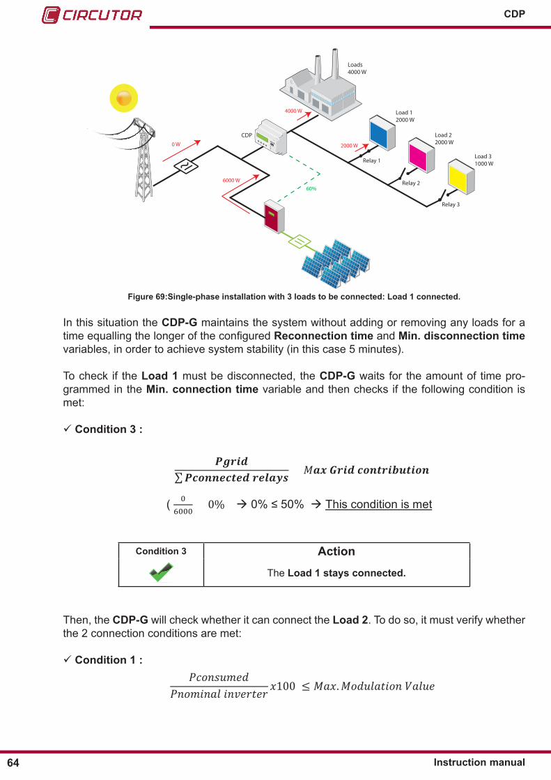
64
CDP
Instruction manual
CDP
6000 W
4000 W
0 W
60%
2000 W
Loads4000 W
Load 12000 W
Relay 1
Load 22000 W
Relay 2
Load 31000 W
Relay 3
Figure 69:Single-phase installation with 3 loads to be connected: Load 1 connected�
In this situation the CDP-G maintains the system without adding or removing any loads for a timeequallingthelongeroftheconfiguredReconnection time and Min� disconnection time variables, in order to achieve system stability (in this case 5 minutes).
To check if the Load 1 must be disconnected, the CDP-G waits for the amount of time pro-grammed in the Min� connection time variable and then checks if the following condition is met:
Condition 3 :
𝑃𝑃𝑃𝑃𝑃𝑃𝑃𝑃𝑃𝑃𝑃𝑃𝑃𝑃𝑃𝑃𝑃𝑃𝑃𝑃𝑃𝑃𝑃𝑃𝑃𝑃𝑃𝑃𝑃𝑃𝑃𝑃𝑃𝑃 𝑃𝑃𝑃𝑃𝑖𝑖𝑃𝑃𝑖𝑖𝑖𝑖𝑃𝑃𝑖𝑖
𝑥𝑥100 ≤ 𝑀𝑀𝑃𝑃𝑥𝑥.𝑃𝑃𝑃𝑃𝑃𝑃𝑃𝑃𝑃𝑃𝑃𝑃𝑖𝑖𝑃𝑃𝑃𝑃𝑃𝑃 𝑖𝑖𝑃𝑃𝑃𝑃𝑃𝑃𝑃𝑃
𝑃𝑃𝑐𝑐𝑐𝑐𝑐𝑐𝑐𝑐𝑐𝑐𝑐𝑐𝑐𝑐𝑐𝑐𝑃𝑃𝑐𝑐𝑚𝑚𝑚𝑚𝑚𝑚𝑉𝑉
⋅ 100
𝑃𝑃Grid
∑𝑃𝑃CG· 100
𝑃𝑃𝑃𝑃𝑃𝑃𝑃𝑃𝑃𝑃𝑃𝑃𝑃𝑃𝑃𝑃𝑃𝑃𝑃𝑃𝑃𝑃𝑃𝑃𝑃𝑃𝑃𝑃𝑃𝑃𝑃𝑃𝑃𝑃 𝑃𝑃𝑃𝑃𝑖𝑖𝑃𝑃𝑖𝑖𝑖𝑖𝑃𝑃𝑖𝑖
𝑥𝑥100 ≤ 𝑀𝑀𝑃𝑃𝑥𝑥.𝑀𝑀𝑃𝑃𝑃𝑃𝑃𝑃𝑃𝑃𝑃𝑃𝑖𝑖𝑃𝑃𝑃𝑃𝑃𝑃 𝑉𝑉𝑃𝑃𝑃𝑃𝑃𝑃𝑃𝑃
( 400010000
𝑥𝑥100 = 40%) 40% ≤ 90% This condition is met
𝑷𝑷𝒈𝒈𝒈𝒈𝒈𝒈𝒈𝒈∑𝑷𝑷𝒄𝒄𝒄𝒄𝒄𝒄𝒄𝒄𝒄𝒄𝒄𝒄𝒄𝒄𝒄𝒄𝒈𝒈 𝒈𝒈𝒄𝒄𝒓𝒓𝒓𝒓𝒓𝒓𝒓𝒓
< 𝑀𝑀𝒓𝒓𝒂𝒂 𝑮𝑮𝒈𝒈𝒈𝒈𝒈𝒈 𝒄𝒄𝒄𝒄𝒄𝒄𝒄𝒄𝒈𝒈𝒈𝒈𝒄𝒄𝒄𝒄𝒄𝒄𝒈𝒈𝒄𝒄𝒄𝒄
( 30005000
= 60%) 60% ≤ 20% This condition is not met
( 06000
= 0%) 0% ≤ 50% This condition is met
( 600010000
𝑥𝑥100 = 60%) 60% ≤ 90% This condition is met
( 08000
= 0%) 0% ≤ 50% This condition is met
( 800010000
𝑥𝑥100 = 80%) 80% ≤ 90% This condition is met
( 100010000
= 10%) 10% ≤ 50% This condition is met
𝑃𝑃𝑃𝑃𝑃𝑃𝑃𝑃𝑃𝑃𝑃𝑃𝑃𝑃𝑃𝑃𝑃𝑃𝑃𝑃𝑃𝑃𝑃𝑃𝑃𝑃𝑃𝑃𝑃𝑃𝑃𝑃𝑃𝑃 𝑃𝑃𝑃𝑃𝑖𝑖𝑃𝑃𝑖𝑖𝑖𝑖𝑃𝑃𝑖𝑖
𝑥𝑥100 ≤ 𝑀𝑀𝑃𝑃𝑥𝑥.𝑃𝑃𝑃𝑃𝑃𝑃𝑃𝑃𝑃𝑃𝑃𝑃𝑖𝑖𝑃𝑃𝑃𝑃𝑃𝑃 𝑖𝑖𝑃𝑃𝑃𝑃𝑃𝑃𝑃𝑃
𝑃𝑃𝑐𝑐𝑐𝑐𝑐𝑐𝑐𝑐𝑐𝑐𝑐𝑐𝑐𝑐𝑐𝑐𝑃𝑃𝑐𝑐𝑚𝑚𝑚𝑚𝑚𝑚𝑉𝑉
⋅ 100
𝑃𝑃Grid
∑𝑃𝑃CG· 100
𝑃𝑃𝑃𝑃𝑃𝑃𝑃𝑃𝑃𝑃𝑃𝑃𝑃𝑃𝑃𝑃𝑃𝑃𝑃𝑃𝑃𝑃𝑃𝑃𝑃𝑃𝑃𝑃𝑃𝑃𝑃𝑃𝑃𝑃 𝑃𝑃𝑃𝑃𝑖𝑖𝑃𝑃𝑖𝑖𝑖𝑖𝑃𝑃𝑖𝑖
𝑥𝑥100 ≤ 𝑀𝑀𝑃𝑃𝑥𝑥.𝑀𝑀𝑃𝑃𝑃𝑃𝑃𝑃𝑃𝑃𝑃𝑃𝑖𝑖𝑃𝑃𝑃𝑃𝑃𝑃 𝑉𝑉𝑃𝑃𝑃𝑃𝑃𝑃𝑃𝑃
( 400010000
𝑥𝑥100 = 40%) 40% ≤ 90% This condition is met
𝑷𝑷𝒈𝒈𝒈𝒈𝒈𝒈𝒈𝒈∑𝑷𝑷𝒄𝒄𝒄𝒄𝒄𝒄𝒄𝒄𝒄𝒄𝒄𝒄𝒄𝒄𝒄𝒄𝒈𝒈 𝒈𝒈𝒄𝒄𝒓𝒓𝒓𝒓𝒓𝒓𝒓𝒓
< 𝑀𝑀𝒓𝒓𝒂𝒂 𝑮𝑮𝒈𝒈𝒈𝒈𝒈𝒈 𝒄𝒄𝒄𝒄𝒄𝒄𝒄𝒄𝒈𝒈𝒈𝒈𝒄𝒄𝒄𝒄𝒄𝒄𝒈𝒈𝒄𝒄𝒄𝒄
( 30005000
= 60%) 60% ≤ 20% This condition is not met
( 06000
= 0%) 0% ≤ 50% This condition is met
( 600010000
𝑥𝑥100 = 60%) 60% ≤ 90% This condition is met
( 08000
= 0%) 0% ≤ 50% This condition is met
( 800010000
𝑥𝑥100 = 80%) 80% ≤ 90% This condition is met
( 100010000
= 10%) 10% ≤ 50% This condition is met
Condition 3 Action
The Load 1 stays connected�
Then, the CDP-G will check whether it can connect the Load 2. To do so, it must verify whether the 2 connection conditions are met:
Condition 1 :
𝑃𝑃𝑃𝑃𝑃𝑃𝑃𝑃𝑃𝑃𝑃𝑃𝑃𝑃𝑃𝑃𝑃𝑃𝑃𝑃𝑃𝑃𝑃𝑃𝑃𝑃𝑃𝑃𝑃𝑃𝑃𝑃𝑃𝑃 𝑃𝑃𝑃𝑃𝑖𝑖𝑃𝑃𝑖𝑖𝑖𝑖𝑃𝑃𝑖𝑖
𝑥𝑥100 ≤ 𝑀𝑀𝑃𝑃𝑥𝑥.𝑃𝑃𝑃𝑃𝑃𝑃𝑃𝑃𝑃𝑃𝑃𝑃𝑖𝑖𝑃𝑃𝑃𝑃𝑃𝑃 𝑖𝑖𝑃𝑃𝑃𝑃𝑃𝑃𝑃𝑃
𝑃𝑃𝑐𝑐𝑐𝑐𝑐𝑐𝑐𝑐𝑐𝑐𝑐𝑐𝑐𝑐𝑐𝑐𝑃𝑃𝑐𝑐𝑚𝑚𝑚𝑚𝑚𝑚𝑉𝑉
⋅ 100
𝑃𝑃Grid
∑𝑃𝑃CG· 100
𝑃𝑃𝑃𝑃𝑃𝑃𝑃𝑃𝑃𝑃𝑃𝑃𝑃𝑃𝑃𝑃𝑃𝑃𝑃𝑃𝑃𝑃𝑃𝑃𝑃𝑃𝑃𝑃𝑃𝑃𝑃𝑃𝑃𝑃 𝑃𝑃𝑃𝑃𝑖𝑖𝑃𝑃𝑖𝑖𝑖𝑖𝑃𝑃𝑖𝑖
𝑥𝑥100 ≤ 𝑀𝑀𝑃𝑃𝑥𝑥.𝑀𝑀𝑃𝑃𝑃𝑃𝑃𝑃𝑃𝑃𝑃𝑃𝑖𝑖𝑃𝑃𝑃𝑃𝑃𝑃 𝑉𝑉𝑃𝑃𝑃𝑃𝑃𝑃𝑃𝑃
( 400010000
𝑥𝑥100 = 40%) 40% ≤ 90% This condition is met
𝑷𝑷𝒈𝒈𝒈𝒈𝒈𝒈𝒈𝒈∑𝑷𝑷𝒄𝒄𝒄𝒄𝒄𝒄𝒄𝒄𝒄𝒄𝒄𝒄𝒄𝒄𝒄𝒄𝒈𝒈 𝒈𝒈𝒄𝒄𝒓𝒓𝒓𝒓𝒓𝒓𝒓𝒓
< 𝑀𝑀𝒓𝒓𝒂𝒂 𝑮𝑮𝒈𝒈𝒈𝒈𝒈𝒈 𝒄𝒄𝒄𝒄𝒄𝒄𝒄𝒄𝒈𝒈𝒈𝒈𝒄𝒄𝒄𝒄𝒄𝒄𝒈𝒈𝒄𝒄𝒄𝒄
( 30005000
= 60%) 60% ≤ 20% This condition is not met
( 06000
= 0%) 0% ≤ 50% This condition is met
( 600010000
𝑥𝑥100 = 60%) 60% ≤ 90% This condition is met
( 08000
= 0%) 0% ≤ 50% This condition is met
( 800010000
𝑥𝑥100 = 80%) 80% ≤ 90% This condition is met
( 100010000
= 10%) 10% ≤ 50% This condition is met

65Instruction manual
CDP
In this case:
𝑃𝑃𝑃𝑃𝑃𝑃𝑃𝑃𝑃𝑃𝑃𝑃𝑃𝑃𝑃𝑃𝑃𝑃𝑃𝑃𝑃𝑃𝑃𝑃𝑃𝑃𝑃𝑃𝑃𝑃𝑃𝑃𝑃𝑃 𝑃𝑃𝑃𝑃𝑖𝑖𝑃𝑃𝑖𝑖𝑖𝑖𝑃𝑃𝑖𝑖
𝑥𝑥100 ≤ 𝑀𝑀𝑃𝑃𝑥𝑥.𝑃𝑃𝑃𝑃𝑃𝑃𝑃𝑃𝑃𝑃𝑃𝑃𝑖𝑖𝑃𝑃𝑃𝑃𝑃𝑃 𝑖𝑖𝑃𝑃𝑃𝑃𝑃𝑃𝑃𝑃
𝑃𝑃𝑐𝑐𝑐𝑐𝑐𝑐𝑐𝑐𝑐𝑐𝑐𝑐𝑐𝑐𝑐𝑐𝑃𝑃𝑐𝑐𝑚𝑚𝑚𝑚𝑚𝑚𝑉𝑉
⋅ 100
𝑃𝑃Grid
∑𝑃𝑃CG· 100
𝑃𝑃𝑃𝑃𝑃𝑃𝑃𝑃𝑃𝑃𝑃𝑃𝑃𝑃𝑃𝑃𝑃𝑃𝑃𝑃𝑃𝑃𝑃𝑃𝑃𝑃𝑃𝑃𝑃𝑃𝑃𝑃𝑃𝑃 𝑃𝑃𝑃𝑃𝑖𝑖𝑃𝑃𝑖𝑖𝑖𝑖𝑃𝑃𝑖𝑖
𝑥𝑥100 ≤ 𝑀𝑀𝑃𝑃𝑥𝑥.𝑀𝑀𝑃𝑃𝑃𝑃𝑃𝑃𝑃𝑃𝑃𝑃𝑖𝑖𝑃𝑃𝑃𝑃𝑃𝑃 𝑉𝑉𝑃𝑃𝑃𝑃𝑃𝑃𝑃𝑃
( 400010000
𝑥𝑥100 = 40%) 40% ≤ 90% This condition is met
𝑷𝑷𝒈𝒈𝒈𝒈𝒈𝒈𝒈𝒈∑𝑷𝑷𝒄𝒄𝒄𝒄𝒄𝒄𝒄𝒄𝒄𝒄𝒄𝒄𝒄𝒄𝒄𝒄𝒈𝒈 𝒈𝒈𝒄𝒄𝒓𝒓𝒓𝒓𝒓𝒓𝒓𝒓
< 𝑀𝑀𝒓𝒓𝒂𝒂 𝑮𝑮𝒈𝒈𝒈𝒈𝒈𝒈 𝒄𝒄𝒄𝒄𝒄𝒄𝒄𝒄𝒈𝒈𝒈𝒈𝒄𝒄𝒄𝒄𝒄𝒄𝒈𝒈𝒄𝒄𝒄𝒄
( 30005000
= 60%) 60% ≤ 20% This condition is not met
( 06000
= 0%) 0% ≤ 50% This condition is met
( 600010000
𝑥𝑥100 = 60%) 60% ≤ 90% This condition is met
( 08000
= 0%) 0% ≤ 50% This condition is met
( 800010000
𝑥𝑥100 = 80%) 80% ≤ 90% This condition is met
( 100010000
= 10%) 10% ≤ 50% This condition is met
Condition 2 :
If Injection margin = 0% Grid Power < 3 x 0.03 x Consumed Power
If Injection margin ≠ 0% Grid Power < 3 x Injection margin x Consumed Power
In this case: 0 < 3 x 0.03 x 6000 → this condition is med
Condition 1 Condition 2 Action
Relay 2 is closed and Load 2 is connected (Figure 63)�
CDP
8000 W
4000 W
0 W
80%
2000 W
2000 W
Loads 4000 W
Load 12000 W
Relay 1
Load 22000 W
Relay 2
Load 31000 W
Relay 3
Figure 70:Single-phase installation with 3 loads to be connected: Load 1 and 2 connected�
In this situation the CDP-G maintains the system without adding or removing any loads for the amountoftimeconfiguredintheReconnection time variable, in order to achieve system sta-bility (in this case 5 minutes).
To check if Load 2 must be disconnected, the CDP-G waits for the amount of time programmed in the Min� connection time variable and then checks if the following condition is met:

66
CDP
Instruction manual
Condition 3 :
𝑃𝑃𝑃𝑃𝑃𝑃𝑃𝑃𝑃𝑃𝑃𝑃𝑃𝑃𝑃𝑃𝑃𝑃𝑃𝑃𝑃𝑃𝑃𝑃𝑃𝑃𝑃𝑃𝑃𝑃𝑃𝑃𝑃𝑃 𝑃𝑃𝑃𝑃𝑖𝑖𝑃𝑃𝑖𝑖𝑖𝑖𝑃𝑃𝑖𝑖
𝑥𝑥100 ≤ 𝑀𝑀𝑃𝑃𝑥𝑥.𝑃𝑃𝑃𝑃𝑃𝑃𝑃𝑃𝑃𝑃𝑃𝑃𝑖𝑖𝑃𝑃𝑃𝑃𝑃𝑃 𝑖𝑖𝑃𝑃𝑃𝑃𝑃𝑃𝑃𝑃
𝑃𝑃𝑐𝑐𝑐𝑐𝑐𝑐𝑐𝑐𝑐𝑐𝑐𝑐𝑐𝑐𝑐𝑐𝑃𝑃𝑐𝑐𝑚𝑚𝑚𝑚𝑚𝑚𝑉𝑉
⋅ 100
𝑃𝑃Grid
∑𝑃𝑃CG· 100
𝑃𝑃𝑃𝑃𝑃𝑃𝑃𝑃𝑃𝑃𝑃𝑃𝑃𝑃𝑃𝑃𝑃𝑃𝑃𝑃𝑃𝑃𝑃𝑃𝑃𝑃𝑃𝑃𝑃𝑃𝑃𝑃𝑃𝑃 𝑃𝑃𝑃𝑃𝑖𝑖𝑃𝑃𝑖𝑖𝑖𝑖𝑃𝑃𝑖𝑖
𝑥𝑥100 ≤ 𝑀𝑀𝑃𝑃𝑥𝑥.𝑀𝑀𝑃𝑃𝑃𝑃𝑃𝑃𝑃𝑃𝑃𝑃𝑖𝑖𝑃𝑃𝑃𝑃𝑃𝑃 𝑉𝑉𝑃𝑃𝑃𝑃𝑃𝑃𝑃𝑃
( 400010000
𝑥𝑥100 = 40%) 40% ≤ 90% This condition is met
𝑷𝑷𝒈𝒈𝒈𝒈𝒈𝒈𝒈𝒈∑𝑷𝑷𝒄𝒄𝒄𝒄𝒄𝒄𝒄𝒄𝒄𝒄𝒄𝒄𝒄𝒄𝒄𝒄𝒈𝒈 𝒈𝒈𝒄𝒄𝒓𝒓𝒓𝒓𝒓𝒓𝒓𝒓
< 𝑀𝑀𝒓𝒓𝒂𝒂 𝑮𝑮𝒈𝒈𝒈𝒈𝒈𝒈 𝒄𝒄𝒄𝒄𝒄𝒄𝒄𝒄𝒈𝒈𝒈𝒈𝒄𝒄𝒄𝒄𝒄𝒄𝒈𝒈𝒄𝒄𝒄𝒄
( 30005000
= 60%) 60% ≤ 20% This condition is not met
( 06000
= 0%) 0% ≤ 50% This condition is met
( 600010000
𝑥𝑥100 = 60%) 60% ≤ 90% This condition is met
( 08000
= 0%) 0% ≤ 50% This condition is met
( 800010000
𝑥𝑥100 = 80%) 80% ≤ 90% This condition is met
( 100010000
= 10%) 10% ≤ 50% This condition is met
𝑃𝑃𝑃𝑃𝑃𝑃𝑃𝑃𝑃𝑃𝑃𝑃𝑃𝑃𝑃𝑃𝑃𝑃𝑃𝑃𝑃𝑃𝑃𝑃𝑃𝑃𝑃𝑃𝑃𝑃𝑃𝑃𝑃𝑃 𝑃𝑃𝑃𝑃𝑖𝑖𝑃𝑃𝑖𝑖𝑖𝑖𝑃𝑃𝑖𝑖
𝑥𝑥100 ≤ 𝑀𝑀𝑃𝑃𝑥𝑥.𝑃𝑃𝑃𝑃𝑃𝑃𝑃𝑃𝑃𝑃𝑃𝑃𝑖𝑖𝑃𝑃𝑃𝑃𝑃𝑃 𝑖𝑖𝑃𝑃𝑃𝑃𝑃𝑃𝑃𝑃
𝑃𝑃𝑐𝑐𝑐𝑐𝑐𝑐𝑐𝑐𝑐𝑐𝑐𝑐𝑐𝑐𝑐𝑐𝑃𝑃𝑐𝑐𝑚𝑚𝑚𝑚𝑚𝑚𝑉𝑉
⋅ 100
𝑃𝑃Grid
∑𝑃𝑃CG· 100
𝑃𝑃𝑃𝑃𝑃𝑃𝑃𝑃𝑃𝑃𝑃𝑃𝑃𝑃𝑃𝑃𝑃𝑃𝑃𝑃𝑃𝑃𝑃𝑃𝑃𝑃𝑃𝑃𝑃𝑃𝑃𝑃𝑃𝑃 𝑃𝑃𝑃𝑃𝑖𝑖𝑃𝑃𝑖𝑖𝑖𝑖𝑃𝑃𝑖𝑖
𝑥𝑥100 ≤ 𝑀𝑀𝑃𝑃𝑥𝑥.𝑀𝑀𝑃𝑃𝑃𝑃𝑃𝑃𝑃𝑃𝑃𝑃𝑖𝑖𝑃𝑃𝑃𝑃𝑃𝑃 𝑉𝑉𝑃𝑃𝑃𝑃𝑃𝑃𝑃𝑃
( 400010000
𝑥𝑥100 = 40%) 40% ≤ 90% This condition is met
𝑷𝑷𝒈𝒈𝒈𝒈𝒈𝒈𝒈𝒈∑𝑷𝑷𝒄𝒄𝒄𝒄𝒄𝒄𝒄𝒄𝒄𝒄𝒄𝒄𝒄𝒄𝒄𝒄𝒈𝒈 𝒈𝒈𝒄𝒄𝒓𝒓𝒓𝒓𝒓𝒓𝒓𝒓
< 𝑀𝑀𝒓𝒓𝒂𝒂 𝑮𝑮𝒈𝒈𝒈𝒈𝒈𝒈 𝒄𝒄𝒄𝒄𝒄𝒄𝒄𝒄𝒈𝒈𝒈𝒈𝒄𝒄𝒄𝒄𝒄𝒄𝒈𝒈𝒄𝒄𝒄𝒄
( 30005000
= 60%) 60% ≤ 20% This condition is not met
( 06000
= 0%) 0% ≤ 50% This condition is met
( 600010000
𝑥𝑥100 = 60%) 60% ≤ 90% This condition is met
( 08000
= 0%) 0% ≤ 50% This condition is met
( 800010000
𝑥𝑥100 = 80%) 80% ≤ 90% This condition is met
( 100010000
= 10%) 10% ≤ 50% This condition is met
Condition 3 Action
The Load 2 stays connected�
At this point, the CDP-G will check whether it can connect the Load 3. To do so, it must verify whether the connection condition is met:
Condition 1 :
𝑃𝑃𝑃𝑃𝑃𝑃𝑃𝑃𝑃𝑃𝑃𝑃𝑃𝑃𝑃𝑃𝑃𝑃𝑃𝑃𝑃𝑃𝑃𝑃𝑃𝑃𝑃𝑃𝑃𝑃𝑃𝑃𝑃𝑃 𝑃𝑃𝑃𝑃𝑖𝑖𝑃𝑃𝑖𝑖𝑖𝑖𝑃𝑃𝑖𝑖
𝑥𝑥100 ≤ 𝑀𝑀𝑃𝑃𝑥𝑥.𝑃𝑃𝑃𝑃𝑃𝑃𝑃𝑃𝑃𝑃𝑃𝑃𝑖𝑖𝑃𝑃𝑃𝑃𝑃𝑃 𝑖𝑖𝑃𝑃𝑃𝑃𝑃𝑃𝑃𝑃
𝑃𝑃𝑐𝑐𝑐𝑐𝑐𝑐𝑐𝑐𝑐𝑐𝑐𝑐𝑐𝑐𝑐𝑐𝑃𝑃𝑐𝑐𝑚𝑚𝑚𝑚𝑚𝑚𝑉𝑉
⋅ 100
𝑃𝑃Grid
∑𝑃𝑃CG· 100
𝑃𝑃𝑃𝑃𝑃𝑃𝑃𝑃𝑃𝑃𝑃𝑃𝑃𝑃𝑃𝑃𝑃𝑃𝑃𝑃𝑃𝑃𝑃𝑃𝑃𝑃𝑃𝑃𝑃𝑃𝑃𝑃𝑃𝑃 𝑃𝑃𝑃𝑃𝑖𝑖𝑃𝑃𝑖𝑖𝑖𝑖𝑃𝑃𝑖𝑖
𝑥𝑥100 ≤ 𝑀𝑀𝑃𝑃𝑥𝑥.𝑀𝑀𝑃𝑃𝑃𝑃𝑃𝑃𝑃𝑃𝑃𝑃𝑖𝑖𝑃𝑃𝑃𝑃𝑃𝑃 𝑉𝑉𝑃𝑃𝑃𝑃𝑃𝑃𝑃𝑃
( 400010000
𝑥𝑥100 = 40%) 40% ≤ 90% This condition is met
𝑷𝑷𝒈𝒈𝒈𝒈𝒈𝒈𝒈𝒈∑𝑷𝑷𝒄𝒄𝒄𝒄𝒄𝒄𝒄𝒄𝒄𝒄𝒄𝒄𝒄𝒄𝒄𝒄𝒈𝒈 𝒈𝒈𝒄𝒄𝒓𝒓𝒓𝒓𝒓𝒓𝒓𝒓
< 𝑀𝑀𝒓𝒓𝒂𝒂 𝑮𝑮𝒈𝒈𝒈𝒈𝒈𝒈 𝒄𝒄𝒄𝒄𝒄𝒄𝒄𝒄𝒈𝒈𝒈𝒈𝒄𝒄𝒄𝒄𝒄𝒄𝒈𝒈𝒄𝒄𝒄𝒄
( 30005000
= 60%) 60% ≤ 20% This condition is not met
( 06000
= 0%) 0% ≤ 50% This condition is met
( 600010000
𝑥𝑥100 = 60%) 60% ≤ 90% This condition is met
( 08000
= 0%) 0% ≤ 50% This condition is met
( 800010000
𝑥𝑥100 = 80%) 80% ≤ 90% This condition is met
( 100010000
= 10%) 10% ≤ 50% This condition is met
In this case:
𝑃𝑃𝑃𝑃𝑃𝑃𝑃𝑃𝑃𝑃𝑃𝑃𝑃𝑃𝑃𝑃𝑃𝑃𝑃𝑃𝑃𝑃𝑃𝑃𝑃𝑃𝑃𝑃𝑃𝑃𝑃𝑃𝑃𝑃 𝑃𝑃𝑃𝑃𝑖𝑖𝑃𝑃𝑖𝑖𝑖𝑖𝑃𝑃𝑖𝑖
𝑥𝑥100 ≤ 𝑀𝑀𝑃𝑃𝑥𝑥.𝑃𝑃𝑃𝑃𝑃𝑃𝑃𝑃𝑃𝑃𝑃𝑃𝑖𝑖𝑃𝑃𝑃𝑃𝑃𝑃 𝑖𝑖𝑃𝑃𝑃𝑃𝑃𝑃𝑃𝑃
𝑃𝑃𝑐𝑐𝑐𝑐𝑐𝑐𝑐𝑐𝑐𝑐𝑐𝑐𝑐𝑐𝑐𝑐𝑃𝑃𝑐𝑐𝑚𝑚𝑚𝑚𝑚𝑚𝑉𝑉
⋅ 100
𝑃𝑃Grid
∑𝑃𝑃CG· 100
𝑃𝑃𝑃𝑃𝑃𝑃𝑃𝑃𝑃𝑃𝑃𝑃𝑃𝑃𝑃𝑃𝑃𝑃𝑃𝑃𝑃𝑃𝑃𝑃𝑃𝑃𝑃𝑃𝑃𝑃𝑃𝑃𝑃𝑃 𝑃𝑃𝑃𝑃𝑖𝑖𝑃𝑃𝑖𝑖𝑖𝑖𝑃𝑃𝑖𝑖
𝑥𝑥100 ≤ 𝑀𝑀𝑃𝑃𝑥𝑥.𝑀𝑀𝑃𝑃𝑃𝑃𝑃𝑃𝑃𝑃𝑃𝑃𝑖𝑖𝑃𝑃𝑃𝑃𝑃𝑃 𝑉𝑉𝑃𝑃𝑃𝑃𝑃𝑃𝑃𝑃
( 400010000
𝑥𝑥100 = 40%) 40% ≤ 90% This condition is met
𝑷𝑷𝒈𝒈𝒈𝒈𝒈𝒈𝒈𝒈∑𝑷𝑷𝒄𝒄𝒄𝒄𝒄𝒄𝒄𝒄𝒄𝒄𝒄𝒄𝒄𝒄𝒄𝒄𝒈𝒈 𝒈𝒈𝒄𝒄𝒓𝒓𝒓𝒓𝒓𝒓𝒓𝒓
< 𝑀𝑀𝒓𝒓𝒂𝒂 𝑮𝑮𝒈𝒈𝒈𝒈𝒈𝒈 𝒄𝒄𝒄𝒄𝒄𝒄𝒄𝒄𝒈𝒈𝒈𝒈𝒄𝒄𝒄𝒄𝒄𝒄𝒈𝒈𝒄𝒄𝒄𝒄
( 30005000
= 60%) 60% ≤ 20% This condition is not met
( 06000
= 0%) 0% ≤ 50% This condition is met
( 600010000
𝑥𝑥100 = 60%) 60% ≤ 90% This condition is met
( 08000
= 0%) 0% ≤ 50% This condition is met
( 800010000
𝑥𝑥100 = 80%) 80% ≤ 90% This condition is met
( 100010000
= 10%) 10% ≤ 50% This condition is met
Condition 2 :
If Injection margin = 0% Grid Power < 3 x 0.03 x Consumed Power
if Injection margin ≠ 0% Grid Power < 3 x Injection margin x Consumed Power
In this case: 0 < 3 x 0.03 x 8000 → this condition is med
Condition 1 Condition 2 Action
Relay 3 is closed and Load 3 is connected (Figure 71)�

67Instruction manual
CDP
CDP
9000 W
4000 W
1000 W
100%
2000 W
2000 W
1000 W
Loads4000 W
Load 12000 W
Relay 1
Load 22000 W
Relay 2
Load 31000 W
Relay 3
Figure 71:Single-phase installation with 3 loads to be connected: Load 1, 2 and 3 connected�
As shown in Figure 71, we can see that although the inverter is 10 kW the existing radiation only allows it to produce 9 kW, so to get 10 kW of consumption it will have to take 1 kW from the grid.
In this situation the CDP-G maintains the system without adding or removing any loads for the amountoftimeconfiguredintheReconnection time variable, in order to achieve system sta-bility (in this case 5 minutes).
To check if Load 3 must be disconnected, the CDP-G waits for the amount of time programmed in the Min� connection time variable and then checks if the following condition is met:
Condition 3 :
𝑃𝑃𝑃𝑃𝑃𝑃𝑃𝑃𝑃𝑃𝑃𝑃𝑃𝑃𝑃𝑃𝑃𝑃𝑃𝑃𝑃𝑃𝑃𝑃𝑃𝑃𝑃𝑃𝑃𝑃𝑃𝑃𝑃𝑃 𝑃𝑃𝑃𝑃𝑖𝑖𝑃𝑃𝑖𝑖𝑖𝑖𝑃𝑃𝑖𝑖
𝑥𝑥100 ≤ 𝑀𝑀𝑃𝑃𝑥𝑥.𝑃𝑃𝑃𝑃𝑃𝑃𝑃𝑃𝑃𝑃𝑃𝑃𝑖𝑖𝑃𝑃𝑃𝑃𝑃𝑃 𝑖𝑖𝑃𝑃𝑃𝑃𝑃𝑃𝑃𝑃
𝑃𝑃𝑐𝑐𝑐𝑐𝑐𝑐𝑐𝑐𝑐𝑐𝑐𝑐𝑐𝑐𝑐𝑐𝑃𝑃𝑐𝑐𝑚𝑚𝑚𝑚𝑚𝑚𝑉𝑉
⋅ 100
𝑃𝑃Grid
∑𝑃𝑃CG· 100
𝑃𝑃𝑃𝑃𝑃𝑃𝑃𝑃𝑃𝑃𝑃𝑃𝑃𝑃𝑃𝑃𝑃𝑃𝑃𝑃𝑃𝑃𝑃𝑃𝑃𝑃𝑃𝑃𝑃𝑃𝑃𝑃𝑃𝑃 𝑃𝑃𝑃𝑃𝑖𝑖𝑃𝑃𝑖𝑖𝑖𝑖𝑃𝑃𝑖𝑖
𝑥𝑥100 ≤ 𝑀𝑀𝑃𝑃𝑥𝑥.𝑀𝑀𝑃𝑃𝑃𝑃𝑃𝑃𝑃𝑃𝑃𝑃𝑖𝑖𝑃𝑃𝑃𝑃𝑃𝑃 𝑉𝑉𝑃𝑃𝑃𝑃𝑃𝑃𝑃𝑃
( 400010000
𝑥𝑥100 = 40%) 40% ≤ 90% This condition is met
𝑷𝑷𝒈𝒈𝒈𝒈𝒈𝒈𝒈𝒈∑𝑷𝑷𝒄𝒄𝒄𝒄𝒄𝒄𝒄𝒄𝒄𝒄𝒄𝒄𝒄𝒄𝒄𝒄𝒈𝒈 𝒈𝒈𝒄𝒄𝒓𝒓𝒓𝒓𝒓𝒓𝒓𝒓
< 𝑀𝑀𝒓𝒓𝒂𝒂 𝑮𝑮𝒈𝒈𝒈𝒈𝒈𝒈 𝒄𝒄𝒄𝒄𝒄𝒄𝒄𝒄𝒈𝒈𝒈𝒈𝒄𝒄𝒄𝒄𝒄𝒄𝒈𝒈𝒄𝒄𝒄𝒄
( 30005000
= 60%) 60% ≤ 20% This condition is not met
( 06000
= 0%) 0% ≤ 50% This condition is met
( 600010000
𝑥𝑥100 = 60%) 60% ≤ 90% This condition is met
( 08000
= 0%) 0% ≤ 50% This condition is met
( 800010000
𝑥𝑥100 = 80%) 80% ≤ 90% This condition is met
( 100010000
= 10%) 10% ≤ 50% This condition is met
𝑃𝑃𝑃𝑃𝑃𝑃𝑃𝑃𝑃𝑃𝑃𝑃𝑃𝑃𝑃𝑃𝑃𝑃𝑃𝑃𝑃𝑃𝑃𝑃𝑃𝑃𝑃𝑃𝑃𝑃𝑃𝑃𝑃𝑃 𝑃𝑃𝑃𝑃𝑖𝑖𝑃𝑃𝑖𝑖𝑖𝑖𝑃𝑃𝑖𝑖
𝑥𝑥100 ≤ 𝑀𝑀𝑃𝑃𝑥𝑥.𝑃𝑃𝑃𝑃𝑃𝑃𝑃𝑃𝑃𝑃𝑃𝑃𝑖𝑖𝑃𝑃𝑃𝑃𝑃𝑃 𝑖𝑖𝑃𝑃𝑃𝑃𝑃𝑃𝑃𝑃
𝑃𝑃𝑐𝑐𝑐𝑐𝑐𝑐𝑐𝑐𝑐𝑐𝑐𝑐𝑐𝑐𝑐𝑐𝑃𝑃𝑐𝑐𝑚𝑚𝑚𝑚𝑚𝑚𝑉𝑉
⋅ 100
𝑃𝑃Grid
∑𝑃𝑃CG· 100
𝑃𝑃𝑃𝑃𝑃𝑃𝑃𝑃𝑃𝑃𝑃𝑃𝑃𝑃𝑃𝑃𝑃𝑃𝑃𝑃𝑃𝑃𝑃𝑃𝑃𝑃𝑃𝑃𝑃𝑃𝑃𝑃𝑃𝑃 𝑃𝑃𝑃𝑃𝑖𝑖𝑃𝑃𝑖𝑖𝑖𝑖𝑃𝑃𝑖𝑖
𝑥𝑥100 ≤ 𝑀𝑀𝑃𝑃𝑥𝑥.𝑀𝑀𝑃𝑃𝑃𝑃𝑃𝑃𝑃𝑃𝑃𝑃𝑖𝑖𝑃𝑃𝑃𝑃𝑃𝑃 𝑉𝑉𝑃𝑃𝑃𝑃𝑃𝑃𝑃𝑃
( 400010000
𝑥𝑥100 = 40%) 40% ≤ 90% This condition is met
𝑷𝑷𝒈𝒈𝒈𝒈𝒈𝒈𝒈𝒈∑𝑷𝑷𝒄𝒄𝒄𝒄𝒄𝒄𝒄𝒄𝒄𝒄𝒄𝒄𝒄𝒄𝒄𝒄𝒈𝒈 𝒈𝒈𝒄𝒄𝒓𝒓𝒓𝒓𝒓𝒓𝒓𝒓
< 𝑀𝑀𝒓𝒓𝒂𝒂 𝑮𝑮𝒈𝒈𝒈𝒈𝒈𝒈 𝒄𝒄𝒄𝒄𝒄𝒄𝒄𝒄𝒈𝒈𝒈𝒈𝒄𝒄𝒄𝒄𝒄𝒄𝒈𝒈𝒄𝒄𝒄𝒄
( 30005000
= 60%) 60% ≤ 20% This condition is not met
( 06000
= 0%) 0% ≤ 50% This condition is met
( 600010000
𝑥𝑥100 = 60%) 60% ≤ 90% This condition is met
( 08000
= 0%) 0% ≤ 50% This condition is met
( 800010000
𝑥𝑥100 = 80%) 80% ≤ 90% This condition is met
( 100010000
= 10%) 10% ≤ 50% This condition is met
Condition 3 Action
The Load 3 stays connected�

68
CDP
Instruction manual
8�- MODBUS MAP
All Modbus map addresses are shown in hexadecimal format.
8.1.- MEASURE PARAMETERS
These parameters only accept the read function.
8�1�1�- POWER AND REGULATION PERCENTAGE
Table 23: Modbus memory map: Power�
Parameter L1 L2 L3 III UnitsActive power of the grid(1) 64-65 66-67 68-69 6A-6B W with 3 decimalsActive power measured in the load 6C-6D 6E-6F 70-71 72-73 W with 3 decimalsActive photovoltaic power 74-75 76-77 78-79 7A-7B W with 3 decimals
(1) The sign indicates if it is consumed or generated.
Table 24:Modbus memory map: Regulation percentageParameter L1 L2 L3 Global UnitsRegulation percentage 7D 7E 7F 7C %
8�1�2�- ENERGÍA, TENSIÓN Y CORRIENTE
Table 25:Modbus memory map: Energy�
Parameter Address UnitsActive three-phase energy measured in the load 80-81 kWh with 3 decimalsActive three-phase energy consumed from the grid 82-83 kWh with 3 decimalsThree-phase active photovoltaic energy 84-85 kWh with 3 decimalsActive three-phase energy injected into the grid 86-87 kWh with 3 decimals
Table 26:Modbus memory map: Current and voltage�
Parameter Channel 1 Channel 2 Channel 3 UnitsCurrent measured in the CDP 88 89 8A AVoltage measured in the CDP 8B 8C 8D V with 1 decimals
8�1�3�- PARAMETERS MEASURED IN THE LOAD
Table 27:Modbus memory map: Parameters measured in the load (Table 1)
Parameter L1 L2 L3 III UnitsPower Factor (PF) 8E-8F 90-91 92-93 94-95 with 3 decimalsVoltage THD 98-99 9A-9B 9C-9D - % with 1 decimalsCurrent THD 9E-9F A0-A1 A2-A3 - % with 1 decimalsReactive power A4-A5 A6-A7 A8-A9 - kvar with 3 decimalsApparent power AA-AB AC-AD AE-AF - kVA with 3 decimals
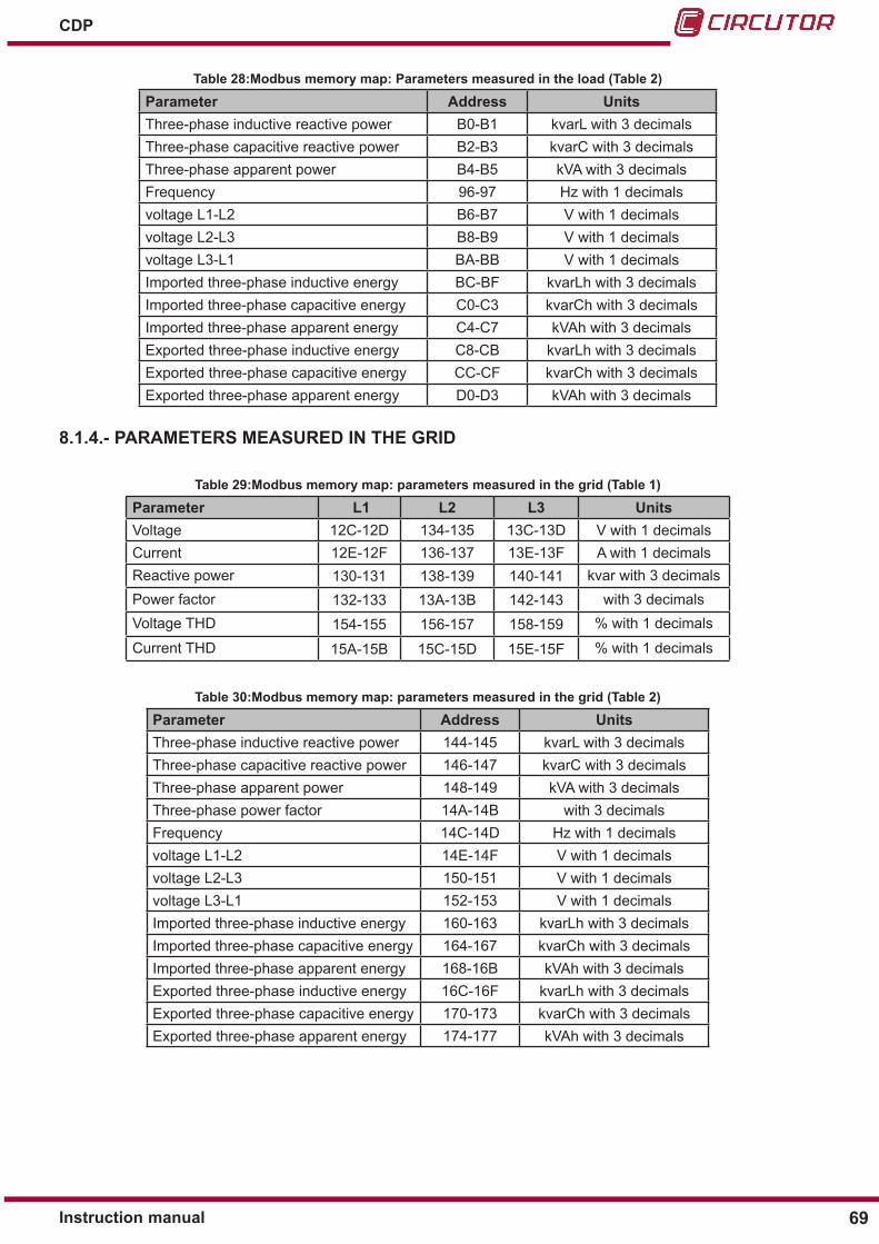
69Instruction manual
CDP
Table 28:Modbus memory map: Parameters measured in the load (Table 2)
Parameter Address UnitsThree-phase inductive reactive power B0-B1 kvarL with 3 decimalsThree-phase capacitive reactive power B2-B3 kvarC with 3 decimalsThree-phase apparent power B4-B5 kVA with 3 decimalsFrequency 96-97 Hz with 1 decimalsvoltage L1-L2 B6-B7 V with 1 decimalsvoltage L2-L3 B8-B9 V with 1 decimalsvoltage L3-L1 BA-BB V with 1 decimalsImported three-phase inductive energy BC-BF kvarLh with 3 decimalsImported three-phase capacitive energy C0-C3 kvarCh with 3 decimalsImported three-phase apparent energy C4-C7 kVAh with 3 decimalsExported three-phase inductive energy C8-CB kvarLh with 3 decimalsExported three-phase capacitive energy CC-CF kvarCh with 3 decimalsExported three-phase apparent energy D0-D3 kVAh with 3 decimals
8�1�4�- PARAMETERS MEASURED IN THE GRID
Table 29:Modbus memory map: parameters measured in the grid (Table 1)
Parameter L1 L2 L3 UnitsVoltage 12C-12D 134-135 13C-13D V with 1 decimalsCurrent 12E-12F 136-137 13E-13F A with 1 decimalsReactive power 130-131 138-139 140-141 kvar with 3 decimalsPower factor 132-133 13A-13B 142-143 with 3 decimalsVoltage THD 154-155 156-157 158-159 % with 1 decimals
Current THD 15A-15B 15C-15D 15E-15F % with 1 decimals
Table 30:Modbus memory map: parameters measured in the grid (Table 2)
Parameter Address UnitsThree-phase inductive reactive power 144-145 kvarL with 3 decimalsThree-phase capacitive reactive power 146-147 kvarC with 3 decimalsThree-phase apparent power 148-149 kVA with 3 decimalsThree-phase power factor 14A-14B with 3 decimalsFrequency 14C-14D Hz with 1 decimalsvoltage L1-L2 14E-14F V with 1 decimalsvoltage L2-L3 150-151 V with 1 decimalsvoltage L3-L1 152-153 V with 1 decimalsImported three-phase inductive energy 160-163 kvarLh with 3 decimalsImported three-phase capacitive energy 164-167 kvarCh with 3 decimalsImported three-phase apparent energy 168-16B kVAh with 3 decimalsExported three-phase inductive energy 16C-16F kvarLh with 3 decimalsExported three-phase capacitive energy 170-173 kvarCh with 3 decimalsExported three-phase apparent energy 174-177 kVAh with 3 decimals

70
CDP
Instruction manual
8�1�5�- PHOTOVOLTAIC PARAMETERS
Table 31:Modbus memory map: Photovoltaic parameters (Table 1)
Parameter L1 L2 L3 UnitsVoltage 190-191 198-199 1A0-1A1 V with 1 decimalsCurrent 192-193 19A-19B 1A2-1A3 A with 1 decimalsReactive power 194-195 19C-19D 1A4-1A5 kvar with 3 decimalsPower factor 196-197 19E-19F 1A6-1A7 with 3 decimalsVoltage THD 1B8-1B9 1BA-1BB 1BC-1BD % with 1 decimals
Current THD 1BE-1BF 1C0-1C1 1C2-1C3 % with 1 decimals
Table 32:Modbus memory map: Photovoltaic parameters (Tabla 2)
Parameter Address UnitsThree-phase inductive reactive power 1A8-1A9 kvarL with 3 decimalsThree-phase capacitive reactive power 1AA-1AB kvarC with 3 decimalsThree-phase apparent power 1AC-1AD kVA with 3 decimalsThree-phase power factor 1AE-1AF with 3 decimalsFrequency 1B0-1B1 Hz with 1 decimalsvoltage L1-L2 1B2-1B3 V with 1 decimalsvoltage L2-L3 1B4-1B5 V with 1 decimalsvoltage L3-L1 1B6-1B7 V with 1 decimalsImported three-phase inductive energy 1C4-1C7 kvarLh with 3 decimalsImported three-phase capacitive energy 1C8-1CB kvarCh with 3 decimalsImported three-phase apparent energy 1CC-1CF kVAh with 3 decimalsExported three-phase inductive energy 1D0-1D3 kvarLh with 3 decimalsExported three-phase capacitive energy 1D4-1D7 kvarCh with 3 decimalsExported three-phase apparent energy 1D8-1DA kVAh with 3 decimals
8�1�6�- DEVICE INFORMATION
Table 33:Modbus memory map: Device information
Parameter AddressVersion 2AF8

71Instruction manual
CDP
8.2.- CONFIGURATION PARAMETERS
These parameters accept the read and write functions.
8�2�1�- STATE OF RELAYSTable 34:Modbus memory map: State of relays (Table 1)
Parameter AddressEstado de los relés 1,2 y 3 BB8
Bit Description State0x0001 Relay 1
1: Activated0: Deactivated0x0002 Relay 2
0x0004 Relay 3
Note: The state of the relays can only be modified when non-critical load management is in manual mode.Note: Higher bits (bit 3, 4, etc.) must be 0 in the write function.
Table 35:Modbus memory map: State of relays (Table 2)
Parameter Address State
Status of relay 4: reverse current relay 1 1: Activated0: Deactivated
8�2�2�- OTHER PARAMETERS
Table 36:Modbus memory map: Other parameters
Parameter AddressInjection Margin E8Activates remote control E6Allowed injection E7
Note: To save in the memory the change in Injection Margin through Modbus, you need to restart the unit.

72
CDP
Instruction manual
9�- TECHNICAL FEATURESAC power supply
Rated voltage 110 ... 240 V ~Frequency 50 ... 60 Hz Consumption 6 ... 10 VAInstallation category CAT III 300V
DC power supply
Rated voltage 12 V Consumption 4 WInstallation category CAT III 300V
Voltage measurement circuit Voltage measurement margin 10 ... 300 V ~Frequency measurement margin 50 ... 60 HzInput impedance 400kΩMinimum measurement voltage (Vstart) 10 V ~Installation category CAT III 300V
Current measurement circuitNominal current (In) … / 250 mAOvercurrent 105% InMaximum current, impulse < 1s According to the current sensorMinimum measurement current (Istart) 10 mAInstallation category CAT III 300 V
Measurement accuracyVoltage measurement 0.5%Current measurement 0.5%Power measurement 0.5%Energy measurement 1%
Relay outputsQuantity 4Maximum voltage open contacts 250 V ~Maximum current 6 A ~Maximum switching power 1500 W Electrical life 60 x 103 cyclesMechanical life 10 x 106 cycles
Digital inputsQuantity 4Type Potential-free contactInsulation Optoisolated
CommunicationsUser interface Ethernet
Communications with the inverterBus RS-232/RS-485/RS-422Baud rate Depending on the inverter (See application notes)Stop bits 1Parity No parity

73Instruction manual
CDP
Communications (Continuation)Communications with other devices
Bus RS-485Protocol ModbusBaud rate 4800-9600-19200-38400Stop bits 1Parity No parity
User interfaceDisplay Alphanumeric LCDKeyboard 4 keysLED 6 LED
Environmental featuresOperating temperature -25ºC ... +70ºCStorage temperature -40ºC ... +85ºCRelative humidity (without condensation) 95%Maximum altitude 2000 mProtection degree IP51
Mechanical featuresDimensions (mm) Figure 72Weight 250 grEnclosure UL94 - V0 self-extinguishing plasticFixing DIN rail
35.5
5 25
4465
45 6590
105
Figure 72: Dimensions CDP�
StandardElectromagnetic compatibility (EMC) -- Part 6-4: Generic standards - Emission standard for industrial environments (IEC 61000-6-4:2006)� UNE-EN 61000-6-4:2007
Safety requirements for electrical equipment for measurement, control and laboratory use -- Part 1: General requirements UNE-EN 61010-1:2011
Electromagnetic compatibility (EMC) -- Part 6-2: Generic standards - Immu-nity for industrial environments UNE-EN 61000-6-2:2006

74
CDP
Instruction manual
10�- TECHNICAL SERVICE
11�- GUARANTEE
• No returns will be accepted and no unit will be repaired or replaced if it is not ac-companied by a report indicating the defect detected or the reason for the return.•The guarantee will be void if the units has been improperly used or the stora-ge, installation and maintenance instructions listed in this manual have not been followed.“Improperusage”isdefinedasanyoperatingorstorageconditioncon-trary to the national electrical code or that surpasses the limits indicated in the technical and environmental features of this manual.• CIRCUTOR accepts no liability due to the possible damage to the unit or other parts of the installation, nor will it cover any possible sanctions derived from a pos-sible failure, improper installation or “improper usage” of the unit. Consequently, this guarantee does not apply to failures occurring in the following cases:- Overvoltages and/or electrical disturbances in the supply;-Water,iftheproductdoesnothavetheappropriateIPclassification;- Poor ventilation and/or excessive temperatures;- Improper installation and/or lack of maintenance;-Buyerrepairsormodificationswithoutthemanufacturer’sauthorisation.
CIRCUTOR guarantees its products against any manufacturing defect for two years after the delivery of the units.
CIRCUTOR will repair or replace any defective factory product returned during the guarantee period.
In the case of any query in relation to unit operation or malfunction, please contact the CIRCUTOR, SA Technical Support Service.
Technical Assistance ServiceVial Sant Jordi, s/n, 08232 - Viladecavalls (Barcelona)Tel: 902 449 459 ( España) / +34 937 452 919 (outside of Spain)email: [email protected]

75Instruction manual
CDP
12�- CE CERTIFICATE

76
CDP
Instruction manual

77Instruction manual
CDP

78
CDP
Instruction manual
13�- UNE 217001 IN CERTIFICATE
Astrom Technical Advisor, S�L� c/Serrano, 8-28001� Madrid. Spain- Phone: + 34 91 146 01 10 www.astromta.com This document cannot be reproduced partially. Nº 11212-1-CER-E1 Page 1 of 4
Product Certificate Number 11212-1-CER-E1
Applicant CIRCUTOR, S.A. Vial Sant Jordi, s/n 08232 Villadecavalls. Barcelona, Spain
Series/ Fronius Galvo / CDP / MC3 / GE CTX
Model/ Fronius Galvo 2.5-1/ CDP-0 / MC3-63 / GE CTX 634052
Type of generating unit Single Phase Inverter / Dynamic Power Controller
Technical Data See page 2 and 3
Standard UNE 217001 IN: 2015: Requisitos y ensayos para sistemas que evi-ten el vertido de energía a la red de distribución.
Having assessed the test report number: 11212-1-TR performed by CERE Testing Laboratory based on the requirements of the EN ISO/IEC 17025:2005
The above-mentioned generating unit complies with the requirements of the: UNE 217001 IN: 2015: Requisitos y ensayos para sistemas que eviten el vertido de energía a la red de distribución.
This certification is according the CERE internal process PET-CERE-09 Rev 9 based on the requirements of the EN ISO/IEC 17065:2012. For this certification process the conformity assessment activities were based on:
• Testing of production samples selected by CERE.
• Audit of quality system according ISO 9001 with certificate number: QMS 140506-01/B issued by a certification body accredited according EN ISO/IEC 17021.
• Inspection of the manufacturing process.
This certificate cancels and supersedes the certificate number: 11212-1-CER.
Madrid, March 07, 2017. This certificate is valid until February 27, 2020
Miguel Martínez Lavin Certification Manager
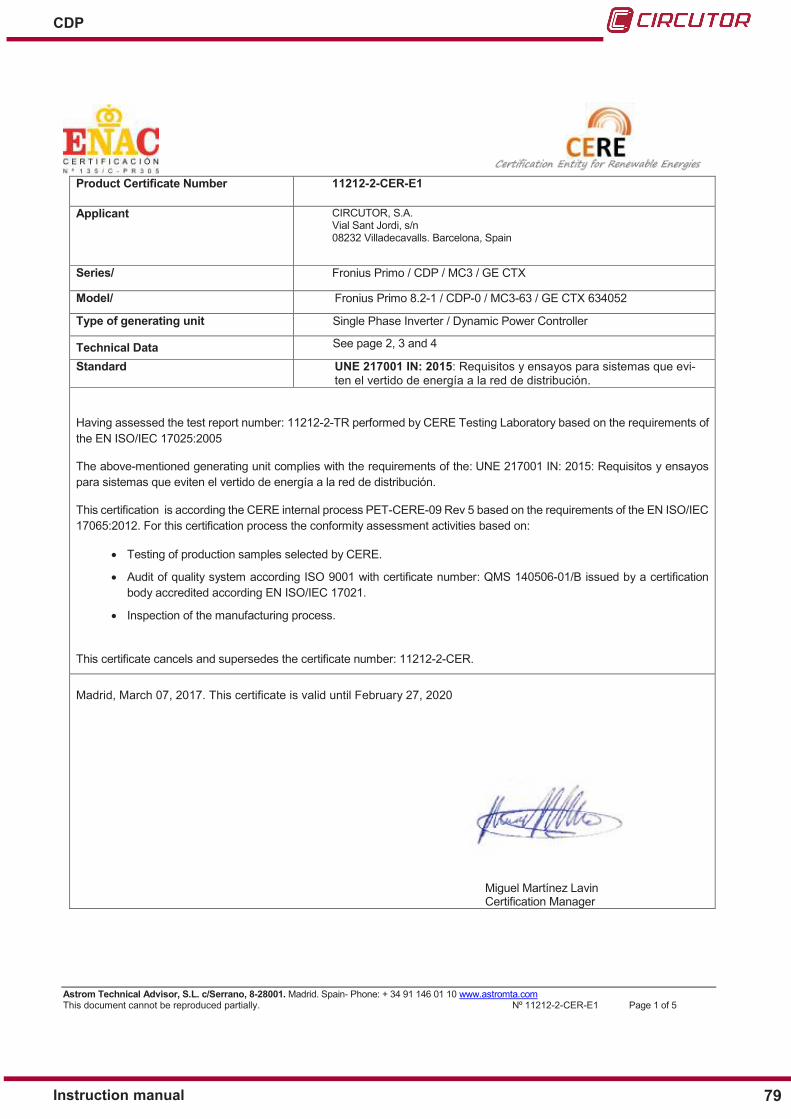
79Instruction manual
CDP
Astrom Technical Advisor, S�L� c/Serrano, 8-28001� Madrid. Spain- Phone: + 34 91 146 01 10 www.astromta.com This document cannot be reproduced partially. Nº 11212-2-CER-E1 Page 1 of 5
Product Certificate Number 11212-2-CER-E1
Applicant CIRCUTOR, S.A. Vial Sant Jordi, s/n 08232 Villadecavalls. Barcelona, Spain
Series/ Fronius Primo / CDP / MC3 / GE CTX
Model/ Fronius Primo 8.2-1 / CDP-0 / MC3-63 / GE CTX 634052
Type of generating unit Single Phase Inverter / Dynamic Power Controller
Technical Data See page 2, 3 and 4
Standard UNE 217001 IN: 2015: Requisitos y ensayos para sistemas que evi-ten el vertido de energía a la red de distribución.
Having assessed the test report number: 11212-2-TR performed by CERE Testing Laboratory based on the requirements of the EN ISO/IEC 17025:2005
The above-mentioned generating unit complies with the requirements of the: UNE 217001 IN: 2015: Requisitos y ensayos para sistemas que eviten el vertido de energía a la red de distribución.
This certification is according the CERE internal process PET-CERE-09 Rev 5 based on the requirements of the EN ISO/IEC 17065:2012. For this certification process the conformity assessment activities based on:
• Testing of production samples selected by CERE.
• Audit of quality system according ISO 9001 with certificate number: QMS 140506-01/B issued by a certification body accredited according EN ISO/IEC 17021.
• Inspection of the manufacturing process.
This certificate cancels and supersedes the certificate number: 11212-2-CER.
Madrid, March 07, 2017. This certificate is valid until February 27, 2020
Miguel Martínez Lavin Certification Manager

80
CDP
Instruction manual
Astrom Technical Advisor, S�L� c/Serrano, 8-28001� Madrid. Spain- Phone: + 34 91 146 01 10 www.astromta.com This document cannot be reproduced partially. Nº 11212-4-CER-E1 Page 1 of 5
Product Certificate Number 11212-4-CER-E1
Applicant CIRCUTOR, S.A. Vial Sant Jordi, s/n 08232 Villadecavalls. Barcelona, Spain
Series/ Fronius Symo / CDP / MC3 / GE CTX
Model/ Fronius Symo 15.0-3/ CDP-0 / MC3-63 / GE CTX 634052
Type of generating unit Three Phase Inverter / Dynamic Power Controller
Technical Data See page 2, 3 and 4
Standard UNE 217001 IN: 2015: Requisitos y ensayos para sistemas que evi-ten el vertido de energía a la red de distribución.
Having assessed the test report number: 11212-4-TR performed by Fundación Tecnalia Research and Innovation based on the requirements of the EN ISO/IEC 17025:2005
The above-mentioned generating unit complies with the requirements of the: UNE 217001 IN: 2015: Requisitos y ensayos para sistemas que eviten el vertido de energía a la red de distribución.
This certification is according the CERE internal process PET-CERE-09 Rev 9 based on the requirements of the EN ISO/IEC 17065:2012. For this certification process the conformity assessment activities were based on:
• Testing of production samples selected by CERE.
• Audit of quality system according ISO 9001 with certificate number: QMS 140506-01/B issued by a certification body accredited according EN ISO/IEC 17021.
• Inspection of the manufacturing process.
This certificate cancels and supersedes the certificate number: 11212-4-CER.
Madrid, March 07, 2017. This certificate is valid until February 27, 2020
Miguel Martínez Lavin Certification Manager

81Instruction manual
CDP

CIRCUTOR, SA Vial Sant Jordi, s/n08232 - Viladecavalls (Barcelona)Tel: (+34) 93 745 29 00 - Fax: (+34) 93 745 29 14 www.circutor.com [email protected]