Instruction for the Cutler-Hammer T Type MPCV …pub/@electrical/... · IB02402001E For more...
32
IB02402001E For more information visit: www.EatonElectrical.com Instruction for the Cutler-HammerT Type MPCV Network Protection Relay Instruction Bulletin Supersedes I.B. 35-581B Pages 1 – 28 dated October 1997 MPCV Communications Relay for Cutler-Hammer/Westinghouse T Network Protectors Rear View MPCV Communications Relay for General Electric T Network Protectors Rear View
Transcript of Instruction for the Cutler-Hammer T Type MPCV …pub/@electrical/... · IB02402001E For more...

IB02402001E For more information visit: www.EatonElectrical.com
Instruction for the Cutler-Hammer
T
Type MPCV
Network Protection Relay
Instruction Bulletin
Supersedes I.B. 35-581B
Pages 1 – 28 dated October 1997
MPCV Communications Relay for Cutler-Hammer/Westinghouse
T
Network Protectors
Rear View
MPCV Communications Relay for General Electric
T
Network Protectors
Rear View

For more information visit: www.EatonElectrical.com IB02402001E
Instruction Bulletin
Page
2
Effective: September 2004
Instruction for the Cutler-Hammer Type MPCVNetwork Protection Relay
READ AND UNDERSTAND THESE INSTRUCTIONS BEFORE
ATTEMPTING ANY ASSEMBLY, OPERATION OR MAINTENANCE
OF THE NETWORK PROTECTORS.
DISCLAIMER OF WARRANTIES AND LIMITATION OF LIABILITY
THERE ARE NO UNDERSTANDINGS, AGREEMENTS, REPRESENTATIONS OR WARRANTIES, EXPRESSED OR IMPLIED, INCLUDING WARRANTIES OF MERCHANTABILITY OR FITNESS FOR A PARTICULAR PURPOSE, OTHER THAN THOSE SPECIFICALLY SET OUT BY AN EXISTING CONTRACT BETWEEN THE PARTIES, ANY SUCH CONTRACT STATES THE ENTIRE OBLIGATION OF SELLER. THE CONTENTS OF THIS DOCUMENT SHALL NOT BECOME PART OF OR MODIFY ANY PRIOR OR EXISTING AGREEMENT, COMMITMENT OR RELATIONSHIP.
The information, recommendations, descriptions and safety notations in the document are based on Eaton’s experience and judgment with respect to MPCV-D AND MPCV-22 RELAYS.
THIS INFORMATION SHOULD NOT BE CONSIDERED TO BE ALL INCLUSIVE OR COVERING ALL CONTINGENCIES. If further information is required, the Eaton Corporation should be consulted.
NO WARRANTIES, EXPRESSED OR IMPLIED, INCLUDING WARRANTIES OF FITNESS FOR A PARTICULAR PURPOSE OR MERCHANTABILITY, OR WARRANTIES ARISING FROM COURSE OF DEALING OR USAGE OF TRADE, ARE MADE REGARDING THE INFORMATION RECOMMENDATIONS, DESCRIPTIONS AND SAFETY NOTATIONS CONTAINED HEREIN. In no event will Eaton be responsible to the use in contract, in tort (including negligence), strict liability or other-wise for any special, indirect, incidental or consequential damage or loss whatsoever including but not limited to dam-age to or loss of use of equipment, plant or power system, cost of capital, loss of profits or revenues, cost of replacement power, additional expenses in the use of existing power facilities, or claims against the user by its customers resulting from the use of the information, recommendations, descriptions and safety notations contained herein.
All possible contingencies which may arise during installation, operation or maintenance, and all details and variations of this equipment do not purport to be covered by these instructions. If further information is desired by purchaser regarding particular installation, operation or maintenance of equipment, the local Eaton representative should be contacted.

IB02402001E For more information visit: www.EatonElectrical.com
Instruction Bulletin
Effective: September 2004 Page
3
Instruction for the Cutler-Hammer Type MPCVNetwork Protection Relay
Table of Contents
Description Page
Introduction . . . . . . . . . . . . . . . . . . . . . . . . . . . . . . . . . .
3
Functional Characteristics . . . . . . . . . . . . . . . . . . . . . . .
3
Trip Function . . . . . . . . . . . . . . . . . . . . . . . . . . . . . . . . . .
4
Close Characteristics . . . . . . . . . . . . . . . . . . . . . . . . . . .
4
Settings . . . . . . . . . . . . . . . . . . . . . . . . . . . . . . . . . .
4
Data Buffer . . . . . . . . . . . . . . . . . . . . . . . . . . . . . . . . . .
4
Pendant Layout . . . . . . . . . . . . . . . . . . . . . . . . . . . . . . . .
5
Instructions for the Type MPCV-D Relay . . . . . . . . . . . .
8
Instructions for the Type MPCV-22 Relay . . . . . . . . . . .
9
Instructions for the Type MPCV-GE Relay. . . . . . . . . . .
10
GE Relay Installation Notes . . . . . . . . . . . . . . . . . . . . . .
11
Technical Specifications . . . . . . . . . . . . . . . . . . . . . . . . .
13
Communication System Using a Laptop . . . . . . . . . . .
17
Communication System. . . . . . . . . . . . . . . . . . . . . . . . .
17
Installation Rules. . . . . . . . . . . . . . . . . . . . . . . . . . . . . . .
23
PowerNet Reason Descriptions . . . . . . . . . . . . . . . . . . .
24
Relay Replacement Guidelines . . . . . . . . . . . . . . . . . . .
25
Relay Conversion Guidelines . . . . . . . . . . . . . . . . . . . . .
26
Curve Drawings. . . . . . . . . . . . . . . . . . . . . . . . . . . . . . . .
27
Table 1 — Network Protector Rating . . . . . . . . . . . . . . .
5
Table 2 — Overvoltage Close Values. . . . . . . . . . . . . . .
8
Table 3 — Terminal Configurations MPCV-D . . . . . . . .
9
Table 4 — Terminal Configuration MPCV-GE . . . . . . . .
10
Table 5 — Trip Amperage as a Function of Percent . . .
15
Table 6 — Terminal Designation . . . . . . . . . . . . . . . . . .
16
Table 7 — PowerNet Reason Descriptions . . . . . . . . . .
24
Table 8 — MPCV-D Replacement Guide . . . . . . . . . . . .
25
Table 9 — MPCV-22 Replacement Guide . . . . . . . . . . .
25
Table 10 — MPCV-2X Replacement Guide . . . . . . . . . .
25
Table 11 — MPCV-GE Replacement Guide . . . . . . . . . .
25
Table 12 — MPCV-P Replacement Guide . . . . . . . . . . .
25
Figure 1 — MPCV Pendant Control Screen. . . . . . . . . .
5
Figure 2 — Digital Control Pendant . . . . . . . . . . . . . . . .
7
Figure 3 — Cutler-Hammer Relay . . . . . . . . . . . . . . . . .
9
Figure 4 — GE Relay . . . . . . . . . . . . . . . . . . . . . . . . . . . .
10
Figure 5 — Jumper Phase A and Phase C Resistors . .
10
Figure 6 — Top and Bottom Terminal Blocks . . . . . . . .
16
Figure 7 — PMCOM5 — mini-MINT . . . . . . . . . . . . . . .
17
Figure 8 — Daisy Chain . . . . . . . . . . . . . . . . . . . . . . . . .
20
Figure 9 — Simple Tap . . . . . . . . . . . . . . . . . . . . . . . . . .
20
Figure 10 — Complex Tab . . . . . . . . . . . . . . . . . . . . . . .
21
Figure 11 — Main Network . . . . . . . . . . . . . . . . . . . . . .
21
Figure 12 — Cable Star . . . . . . . . . . . . . . . . . . . . . . . . . .
22
Figure 13 — Cable Branch . . . . . . . . . . . . . . . . . . . . . . .
22
Figure 14 — Straight Closing Curve . . . . . . . . . . . . . . .
27
Figure 15 — Circular Closing Curve . . . . . . . . . . . . . . .
28
Figure 16 — Reverse Trip, Sensitive Curve. . . . . . . . . .
29
Figure 17 — Watt-Trip with Non-Sensitive Range . . . .
30
Figure 18 — Watt-Var with Non-Sensitive Trip . . . . . . .
31
Introduction
The Type MPCV microprocessor controlled relays are designed to replace the Type CN-33 electromechanical master relay, the Type CNJ electromechanical phasing relay, and the Type BN electromechanical desensitizing relay. The MPC series relays use the same voltage and current inputs as do the electromechanical equivalent. They also continually moni-tor voltage across an open breaker and current through a closed breaker, and perform the following functions.
A. The trip contact will close upon balanced fault conditions if the positive sequence power flow is out of the network.
B. The close contact will close if the ensuing positive sequence power will be into the network.
C. The trip contact will close upon the flow of reverse magnetizing current of its associated transformer.
The MPCV series of relay will mount on standard existing CMD, CM-22 and CM52 network protectors utilizing the present system of low voltage or high voltage relay mounting studs, without breaker wiring modification.
Functional Characteristics
All measurements in the relay are made as net voltages and currents, computed as the positive sequence voltage and cur-rent (represented as V1X or l1), and the negative sequence voltage and current (represented as V2X or l2). The network positive and negative voltages sequence are denoted V1N and V2N respectively. The other important voltage is the phasing voltage, which is the difference between the trans-former and network voltages, whose sequence components are denoted V1P and V2P.
The V1N is defined as the reference phasor for all phase mea-surements, and the normal phase-to-neutral voltage (1 P.U.) is defined as 125 Vac rms. From this, the basis func-tional requirements are graphically depicted in
Figures 14
and
15
.
WARNING
THE MPCV RELAYS ARE DESIGNED TO BE USED ON NETWORK PROTECTORS WHICH HAVE BEEN WIRED FOR 216Y/125 VOLT OR 480Y/277 VOLT SERVICE USING RELAY POTENTIAL TRANSFORMERS. THIS RELAY IS DESIGNED TO OPERATE AT 125 VOLTS (LINE TO GROUND). DO NOT ATTEMPT TO APPLY THIS RELAY ON ANY OTHER SYSTEM VOLTAGE OR CONFIGURATION. SPECIAL STYLES ARE AVAILABLE FOR 480-VOLT APPLICATION.
FAILURE TO FOLLOW THESE INSTRUCTIONS COULD RESULT IN SEVERE PERSONAL INJURY, DEATH, AND/OR PRODUCT OR PROPERTY DAMAGE.

For more information visit: www.EatonElectrical.com IB02402001E
Instruction Bulletin
Page
4
Effective: September 2004
Instruction for the Cutler-Hammer Type MPCVNetwork Protection Relay
Trip Function
Figure 16
diagrams the current-induced trip characteristics. The positive sequence current l1 is multiplied by the cosine of the angle of its phasor related to V1N. If the resulting sign is negative, then reverse power-flow is indicated. The trip level (l1COSØ) for this can be adjusted from .05 to 5% of rated current. The cosine multiplication operation results in the straight line which is perpendicular to the phasor.
A selection to a watt-var trip curve can be made through the hand-held pendant which will permit 3-phase balanced trip characteristics, as well as tripping when the negative sequence voltage exceeds .06 P.U.
The BN function can be initialized to modify the characteris-tics and timing of the reverse-current trip conditions. This adds to the basic detection requirements that the true rms value of the reverse current exceeds some settable threshold between 50% and 250% of the protector CT rating. When the magnitude of the reverse current is less than the settable threshold, a trip will occur if the condition exists for an adjustable time period of 0 to 5 minutes. The BN function is standard on all MPC relays.
Close Characteristics
Figure 14
also diagrams the voltage regions for close, float and trip operation when the protector is open. Under extreme conditions when the protector is open, a trip is called for to prevent a dangerous manual close operation. With the protec-tor open and the network and transformer voltages normal and balanced, positive sequence phasing voltage (V1P) is measured. If V1P is in the close region, the relay makes its close contact. If V1P is not in the close region, but is less than .06 P.U., then the float is called for, as this voltage difference is not deemed dangerous regardless of the phase relation-ships, and manual close of the protector would not exceed the breaker capacity. If V1P is greater than .06 P.U. and does not lie in the close region, the trip is called for to prevent manual closing. The relay also calls for trip under all rolled and crossed phase conditions, even when either the transformer side or the network side of the protector is de-energized.
The close contact will close only in the quadrant defined by the two lines, termed master and phasing. The phasing line, emanating from 0, defines a minimum phase angle of the phasing voltage ahead of the network voltage for closing, which is selectable at +5, -5, -15 or -25 degrees. The master line sets a minimum difference between the transformer and network voltage, settable from .0008 to .02 P.U. at 0 degrees (in phase). This line exhibits a slope of 7.5 degrees.
If the network side is de-energized, and the transformer side is energized, the close contact will close, if V1N is less than .1 P.U., and V2N is less than .06 P.U., and V1P exceeds .8 P.U. Note that, as stated before, if V2P exceeds .2 P.U., then the trip contact will close, indicating crossed phases on either the transformer side or the network side. Also note, that if the phases are crossed on both the transformer and the net-work side, V2P could be very close to or equal to zero, but the trip contact will close as V1N is less than 0.1 P.U. and V1P is less than .8 P.U.
The other closing curve characteristic option available is the curved line closing curve which maintains the same value of phasing volts from the -25 to +90 degree quadrants (refer to
Figure 15
).
Any close conditions must exist for 500 ms before the close contact will close.
Settings
All settings can be altered through a digital control pendant which plugs into the unit while mounted on the network pro-tector breaker. When not in use, the pendant may be stored separate from any network protector location, most conve-niently with the network protector test kit. While the pendant is plugged in, actual trip and close operations will be inhibited and the amber float light will flash. The pendant has a display for the readout of the set points and a keyboard to set them.
Refer to
Figure 1
for pendant layout.
Data Buffer
There are two data buffers for event logging. These buffers are volatile and they can be lost when power is lost or when downloaded to PowerNet
E
Event Log.
1. Waveform Capture Buffer
is a buffer that contains 16 cycles of data sampled 32 times per power cycle that includes the transformer and network voltages, currents and trip (reasons) flags which is about 9.3 kb total. This single buffer capable of storing one trip event is stored in a volatile memory until the next download or power loss occurs. The data are captured in two ways.
Trip Buffer
is created automatically by the MPCV upon detec-tion of any trip condition. This buffer remains in the MPCV until PowerNet unlocks (frees) the buffer, which it will do once it completes downloading of all the data, or upon a com-plete loss of power. Note that any subsequent trips of the MPCV with a filled trip buffer in the locked state will NOT be captured, i.e., the Trip buffer is NOT overwritten by subsequent trips.
Waveform Buffer
is requested by user using the PowerNet that can also be cleared upon downloading the information, but unlike the trip buffer, it also can be written over by a subsequent user waveform capture request. This buffer is volatile and sensitive to power loss.
2. Time-Stamp Trip Buffer
— Each trip operation of the relay is logged in this buffer, with each trip generating a 6-message INCOM
E
buffer (18 bytes). This records the time stamp and state of all the trip flags for the particular trip. No sampled waveforms are part of this buffer. The MPCV can store up to 15 time stamped events before its buffer queue is filled up. As the TSE buffer(s) is/are read by PowerNet, they can be entered into the PowerNet Event Log, as they are deleted from the MPCV queue. Should PowerNet remain disconnected from a relay for extended times, and should that MPCV trip more than 15 times, the most recent 15 events will remain stored in the relay so long as power is not removed from the relay.

IB02402001E For more information visit: www.EatonElectrical.com
Instruction Bulletin
Effective: September 2004 Page
5
Instruction for the Cutler-Hammer Type MPCVNetwork Protection Relay
Pendant Layout
Figure 1. MPCV Pendant Control Screen (Firmware: 1.012 or Later Version)
1
Appears only if communications enabled.
Note:
Scroll through the entire display to verify set point selections.
HZ=60
The cycles per second can be changed by entering the large up or down arrow keys. The selections are HZ=60 or HZ=50. Make your selection and enter the NEXT key to view the next line.
SYS VOLTS
The system voltage selection is the line-to-line voltage from 216 volts through and including 600 volts. The selections are made by entering the small up and down arrow keys. Entering the large up and down arrow keys permits a fast scroll of the voltages, but it also will skip several selections scrolling top to bottom. Using the small arrow keys permits viewing each voltage selection. Make your selection and enter the NEXT key to view the next line.
CBA=OFF
The relay is switchable in sequence rotation, but assumes an ABC counter-clockwise rotation. If the relay is to be applied on a CBA counter-clockwise system, then the selection must be changed to CBA=ON. This can be changed by entering the large up or down arrow keys. Make your selection and enter the NEXT key to view the next line.
Note:
If the wrong sentence is selected, the relay upon power-up will give a trip indication.
CT RATIO
This refers to the current transformer (CT) primary rating. For example, an 1875-ampere network protector will have 1600/5 CTs. The CT RATIO must be set to 1600. These ratings can be set in increments of 500 (1000 for large arrow) by entering the small up and down arrow keys. Make your selection and enter the NEXT key to view the next line.
Table 1. Network Protector Rating
Note:
GE offers a 3500/5.
Pendant Program Default Range
HZ=60 (60) [50, 60]SYS VOLTS= (216) [216, 380, 400, 416, 433, 480, 600]CBA=OFF (OFF) [ON – OFF]CT RATIO= (800) [800, 1200, 1600, 2000, 3000, 3500]ST ML=ON ST ML=OFF (ON) [ON – OFF]ML=1.00V ML=1.00V (1.00) [.5 – 5.4]PL=-5º PL=-5º (-5) [+5, 0, -5, -10, -15, -25]
LH ML=9º (90) [60 – 90]RT=.20% (.20) [.05 – 5]TD=.00s (0) [0, INF, 0 – 300]OC=0% (0) [0 – 250]WV=OFF (OFF) [ON – OFF]PUMP PROTEC=OFF PUMP PROTEC=ON (OFF) [ON – OFF[
BRK CYCLES=3 (3 – 20) (3) [3 – 20]PUMP TIME=30s (30 – 300) (120) [30 – 300]PMP LOCKOUT RES=15m (15) [15 – 60]
AUX 2 1 =NOT USED
AUX 3 1 =NOT USED AUX 3=USEDAUX 3 ALRM=DISABLEAUX 3 CONTCT=NO
AUX 4 1 =NOT USEDINCOM CODE 1 =1999 (If communications enabled, random if not)INCOM SETPT 1 =ONINCOM OPEN 1 =ONINCOM CLOSE 1 =OFFINCOM ADR 1 =20YEAR=MNTH=DAY=HR=MIN=
NWPRating
CT Applied
80012001600
800/51200/51600/5
187520002250
1600/52000/52000/5
250028253000
2500/52500/53000/5
350045005100
3000/53000/53000/5

For more information visit: www.EatonElectrical.com IB02402001E
Instruction Bulletin
Page
6
Effective: September 2004
Instruction for the Cutler-Hammer Type MPCVNetwork Protection Relay
ST ML=ON
The ST ML=ON refers to the straight line master line setting. This is the traditional master line which has a slope of 7 to 7.5 degrees (refer to
Figure 14
). Entering the large arrow up and down key will change the ST ML=ON to ST ML=OFF. Selecting the straight master line to equal off changes the closing characteristics to the circular master line (refer to
Figure 15
). The circular master line allows the relay to close at the same ML setting and at any angle between the LH MH and PL settings. It is useful in those areas where the network load is lighter than normal. This function permits the relay to call for a close at lower loads while assuring the watt flow will be into the network. Make your selection and enter the NEXT key to view the next line.
ML=1.00V
This is the overvoltage phasing voltage, which is the differ-ence between the transformer and network line to ground voltages. This value represents the in-phase or 0 degree value. The Master Line value can be changed at 0.20 volt increments by entering the large up or down arrow keys. Adjustments of 0.10 volt can be obtained by entering the small up or down arrow key.
Make your selection and enter the NEXT key to view the next line.
PL=-5º
This refers to the Phasing Line adjustment (refer to
Figure 14
and
15
). The phasing line can be changed from +5 to -25 degrees in 5-degree increments. Make your selection and enter the NEXT key to view the next line.
LH ML=90º
(viewed only if ST ML=OFF)The Left Hand Master Line can be viewed whenever the ST ML=OFF, or the circular master line is enabled.
Figure 15
shows the Left-Hand Master Line adjustment region from +60 to +90 degrees. This is selectable by using the small arrow up and down keys in 5-degree increments for small arrow and 10-degree increments for large arrow. Make your selection and enter the NEXT key to view the next line.
RT=.20%
The Reverse Trip setting is calibrated at 180 degrees and is selectable in 0.20% increments when using the large up and down arrow keys and in 0.01% increments when using the small up and down arrow keys. Refer to
Table 5
Trip Amper-age as a Function of CT Primary from .05 to 5% on
Page 15
. This table tabulates the most active trip region selections. The RT setting is referred to as the sensitive trip region. Make your selection and enter the NEXT key to view the next line.
TD=0
This represents the Time Delay setting which is divided into three separate areas.
1. TD=0 With a zero setting, there is no time delay associated with tripping. Sets relay to respond on RT set-ting only.
2. TD=0.25 to 300 seconds. This is selectable in 20-sec-ond increments when using the large up and down arrow keys and is selectable in 0.25-second increments when using the small up and down arrow keys. This represents time delay on tripping in seconds. Sets the relay to respond on RT setting with Time Delay and respond instantaneously to OC setting.
3. TD=INF This is selectable from the TD=0 mode by entering the small arrow down key. Sets the relay to non-sensitive tripping and respond instantaneously to OC set-ting only. It overrides the sensitive trip setting.
Make your selection and enter the NEXT key to view the next line.
OC=0This represents the overcurrent (OC) instantaneous pickup point of the relay. There are two selections possible in this mode, which are:
1. OC=0There is no instantaneous overcurrent pickup point selected. This can be the situation whenever the TD setting equals 0.
2. OC=1 to 250%This is selectable in 20% increments by entering the large up and down arrow keys or in 1% increments by entering the small up and down arrow keys.
Note: If TD=INF or if TD=0.25 to 300 seconds, you will be directed to make an OC setting other than 0.
You can also select an OC setting other than 0 if just the sen-sitive trip range (RT) is being used. The sensitive trip range spans from .05% to .5%. This can be further extended by engaging the OC setting. Make your selection and enter the NEXT key to view the next line.
WV=OFFThe relay can be selected to engage the watt-var trip charac-teristic by entering the large up arrow key, changing the WV=OFF to WV=ON. The new “Boomerang Watt-Var” trip curve is shown in Figure 5. Note that the new curve permits balanced 3-phase tripping under reverse magnetizing condi-tions, while at the same time can handle phase unbalanced conditions which can exist on overhead primary circuits. Again, the OC setting can be engaged which will add a non-sensitive trip region to the tripping characteristic.
Make your selection and enter the NEXT key to view the next line.
PUMP PROTEC= OFFThe MPCV relay incorporates an innovative system where by the operator can select to protect the network protector breaker from pumping. If the PUMP PROTEC=OFF, then there is no pump protection installed. Entering the large up and down arrow keys will change the PUMP PROTEC=ON. If the PUMP PROTEC=OFF, and the NEXT key is entered, the screen displays INCOM ADR, which starts the communication information. See below. If the PUMP PROTEC=ON and the NEXT key is entered, BRK CYCLES=3 is displayed. This is selectable from 3 to 20 cycles. If the NEXT key is entered, the next line displays PUMP TIME=30, which is selectable from 30 to 300 seconds. If the breaker opens and closes its contacts equal to or exceeding the BRK CYCLES in the speci-fied number of seconds as defined by the PUMP TIME, the breaker will trip and lock open.
WARNINGTHE TD=INF WILL DISABLE THE SENSITIVE TRIP MODE AND WILL ONLY PERMIT TRIPPING OF THE NETWORK PROTECTOR AT THE SELECTED OC VALUE.

IB02402001E For more information visit: www.EatonElectrical.com
Instruction BulletinEffective: September 2004 Page 7
Instruction for the Cutler-Hammer Type MPCVNetwork Protection Relay
RESET TIMEWith the PUMP PROTEC=ON, the program will ask for a breaker reset time, which is initiated if the BRK CYCLES and PUMP TIME are exceeded in value. The breaker, through the relay, will trip and lock out, thereby preventing a reclosure. The reset time has a default value of 15 minutes, but is capable of being extended up to 60 minutes with the pendant controller in 1-minute increments (10 minutes with larger arrow). The reset time permits the closing motor to cool its field coils before call-ing on the motor to attempt another breaker closure, thereby extending the useful life of the network breaker closing motor.
Make your selection and enter the NEXT key to view the next line.
The following pendant inputs deal with the communications information. If the MPCV Relay is not connected to an operat-ing communications system, the following set points can be by-passed by entering the SAVE button at this time.
If the communication system will be or now is operational, the following set points must be entered.
AUX 2 OFF/ONIf you are using the AUX 2 position, you must select the AUX 2 port to be ON. Once the NEXT key is entered, you must select whether the device being monitored is going to show up on the front end screen as an alarm (ENABLE) or only status (DISABLE). Further, you must indicate whether the contact being utilized is normally open (NO) or normally closed (NC). The convention used is that the NO or NC state is that state in which the alarm is not enabled. Changing the contact state then will ENABLE the alarm. Refer to Pages 9 and 10 for the terminal block wiring configuration of the AUX ports.
Repeat as required for additional AUX 3 and AUX 4 inputs.
Make your selection and enter the NEXT key to view the next line.
INCOM ADR =This is a hexadecimal input which must agree with the relay address as listed on the main screen of the communications program. No two relays should have the same address code. The code can be changed by using the large and small, up and down arrow keys. Install this value and determine that it matches the relay location, as determined by the system operator, and enter the NEXT key to view the next line.
Note: If a MPCV Relay is provided with communications turned OFF, communications can be activated in the field by a qualified Eaton ser-vice representative.
INCOM SETPT=ONThe default setting is ON with the capability to change to OFF. If the INCOM SETPT=OFF, this prevents a user from remotely changing set points through the IMPACC Series III or PowerNetE software.
INCOM OPEN=ONThe default setting is ON with the capability to change to OFF. If the INCOM OPEN=OFF, this prevents a user from remotely opening the breaker through the IMPACC Series III or Power-Net software. This also effectively disables the set point down-load, as the breaker must be ROBO’d (Remote Open, Blocked Open) before any set points can successfully be downloaded.
INCOM CLOSE=ONIf the INCOM CLOSE=ON, this permits a protected remote close status which reduces the ML value to its operational lowest point for a time period of 10 seconds. This requires PowerNet software to enable this feature. Changing this setting to OFF locks out the remote close feature.
YEAR =The year as a two-digit number is entered. It understands 00 as the year 2000. Use the small arrow keys to change the value. Make your selection and enter the NEXT key to view the next line.
MNTH =The month is entered as a number from 1 to 12. Use the small arrow keys to change the value. Make your selection and enter the NEXT key to view the next line.
DAY =The day is entered as a number from 1 to 31. Use the small arrow keys to change the value. Make your selection and enter the NEXT key to view the next line.
HR =The hour is based on a 24-hour military clock. Enter a number from 00 to 24. Use the small arrow keys to change the value. Make your selection and enter the NEXT key to view the next line.
MIN =Enter the minutes by selecting a value from 00 to 59. Use the small arrow keys to change the value. Make your selection and enter the NEXT key to view the next line.
Figure 2. Digital Control Pendant, Style No. 8312A63H01
Save the entire menu selection by depressing the SAVE key. Once the SAVE key has been de-pressed, all of the set points will be stored within the relay’s memory. The FLOAT light will become illuminated solid, not flashing, and the pendant screen will clear. You have now completely calibrated the relay.
Note: With the MPCV Relay, you can change individual set points without having to review the entire menu. Single entries can be now changed by inserting the pendant’s RS-232 plug into the relay’s connec-tor, enter the EDIT key and scroll down to the line you wish to change. Once the change has been made, the SAVE key can then be de-pressed.

For more information visit: www.EatonElectrical.com IB02402001E
Instruction BulletinPage 8 Effective: September 2004
Instruction for the Cutler-Hammer Type MPCVNetwork Protection Relay
Instructions for the Type MPCV-D Relay used on Type CMD, 216 Volt, Network Protectors
I. Installation
a. Remove the CN-33 master relay and the CNJ phasing relay, as well as the BN relay. Install a BN dummy or jack plate if a BN relay was removed. If there is no BN relay, but the position is taken by a BN dummy plate or BN jack plate. DO NOT REMOVE THE BN DUMMY OR JACK PLATE.
b. Install Style No. 508B559G01 phasing jumper plate in the location of the CNJ phasing relay.
c. Install the Type “MPCV”, Style No. 6417C82G01, in location of the CN-33 master relay.
If the network protector is wired for an electromechanical watt-var relay, the wiring must be changed over to the watt trip characteristic. Refer to l.B. 35-552, Pages 36 – 37. The MPCV can be set for a watt or watt-var trip characteristic. Although its input is connected as a watt characteristic, the change to watt-var is accomplished by changing the “WV” set point from OFF to ON.
II. Calibrationa. Connect a network protector portable test kit to the
network protector. Specific instructions for performing this task are contained in I.B 35-556.
b. Power-up the test kit in the relay test mode. Set the test kit to zero phasing volts, either in phase or at 60 degrees. Once the test set is powered with zero phas-ing volts, (the Variac set to zero), the MPCV Relay will advance to float. This indicates that the power-up mode of the relay is correct. Connect the setting pendant to the relay, by plugging the setting pendant into the exposed 9 pin “D” connector.
Note: Note the connector and plug are polarized to prevent improper connection.
c. De-press the EDIT key to begin the “Edit” mode.
Note: At this point, the amber float light will begin to flash and the first set point, with its loaded value, will appear on the display of the pendant. While in this mode, the relay will not change state and is effectively inoperable for normal relay functions.
d. To change a set point, de-press the large or small, up or down arrow keys for large or small increment adjustments until the desired value appears on the dis-play.
e. Once the desired value is obtained, de-press the NEXT key. The program will automatically step to the next set point to be set.
f. Continue to adjust each set point by repeating Steps d and e above until all the set points have been satisfied.
Note: The starting set point is HZ=60. Refer to the settings on Page 5.
Note: When setting the master line values on a 216 volt relay being used on a 480 volt system, the phasing voltage necessary to close the relay is not directly indicated. The relay calibration on this system is determined by multiplying the master line setting by 2.2. Refer to Table 2.
Table 2. Overvoltage Close Values for 480 Volt Units Using Potential Transformers
Approximate phasing volts required to close the relay contacts, in phase, equals 2.2 times the “MPC” relay setting,
Note: If the BN time delay is not required, make certain that the time delay is set to zero (TD=0).
g. Once ALL the set points have been set, de-press the SAVE key. The display will go blank and the float light will remain constantly ON.
Note: If changing only one or two of the set points, the entire menu need not be reviewed prior to de-pressing the SAVE key.
h. Remove the pendant from the relay; the relay calibration is now complete.
Note: On all 216 volt units, the master line (ML) value equals the phasing volts required to close the relay contacts, in phase.
WARNINGBEFORE PROCEEDING FURTHER, MAKE CERTAIN THAT THE NETWORK PROTECTOR IS DE-ENERGIZED AND IS WITHDRAWN FROM THE ENCLOSURE ON THE EXTENSION RAILS. SPECIFIC INSTRUCTIONS FOR PERFORMING THESE TASKS ARE CONTAINED IN THE LATEST REVISION OF INSTRUCTION BOOK 1.B. 35-552. THOSE INSTRUCTIONS MUST BE CONSULTED AND FOLLOWED.
Overvoltage Close Value Desired Master Line (ML)SettingAt 60 Degrees In Phase
.70 V1.45 V2.13 V
.45 V .90 V1.32 V
ML = .20ML = .40ML = .60
2.85 V3.55 V4.28 V
1.75 V2.20 V2.60 V
ML = .80ML = 1.00ML = 1.20
5.00 V5.70 V6.40 V
3.05 V3.50 V4.00 V
ML = 1.40ML = 1.60ML = 1.80
WARNINGDO NOT FUNCTIONALLY OPERATE (TRIP AND CLOSE) THE NETWORK PROTECTOR BREAKER WITH THE SETTING PENDANT CONNECTED INTO THE RS-232 PORT. CALIBRATION OF THE MPCV MUST BE MADE WITH THREE-PHASE POTENTIAL AND ONLY AFTER THE FLOAT LIGHT IS ILLUMINATED. AT THE END OF THE CALIBRATION SEQUENCE, THE PENDANT MUST BE REMOVED PRIOR TO OPERATION OF THE BREAKER.

IB02402001E For more information visit: www.EatonElectrical.com
Instruction BulletinEffective: September 2004 Page 9
Instruction for the Cutler-Hammer Type MPCVNetwork Protection Relay
Instructions for the Type MPCV-22 Relay Used on a Type CM-22, 216 Volt, Network ProtectorNote: Also applicable to the Type MPCV-22 Relays supplied on Type CMR Network Protectors.
Installation (General)
A. Remove the CN-33 master relay and the CNJ phasing relay, as well as the BN relay. Install a BN dummy or jack plate if a BN relay was removed. If there is no BN relay, but the position is taken by a BN dummy plate or BN jack plate. DO NOT REMOVE THE BN DUMMY OR JACK PLATE.
B. Install Style No. 508B559G01 phasing jumper plate in the location of the CNJ phasing relay.
C. Install the Type MPCV-22 Relay, Style No. 6417C83G01, in location of the CN-33 master relay. If the network pro-tector is wired for an electromechanical watt-var relay, the wiring must be changed over to the watt tip charac-teristic. Refer to I.B. 35-552, Pages 36 – 37. The MPCV can be set for a watt or watt-var trip characteristic. Although its input is connected as a watt characteristic, the change to watt-var is accomplished by changing the “WV” set point from OFF to ON.
D. Proceed to Section II of the MPCV-D instructions (calibration section). Refer to Page 8.
Note: For CM-22 or CMR breakers which have been rewired to accept the MPCV, phase 4 or phase 5 relay, the Type MPCV-2X is a direct replacement. Style Number is 6417C83G03.
Table 3. Terminal Configurations
Figure 3. Cutler-Hammer Relay
Note: For Communication with Cutler-Hammer style relays.
Status input always uses AUX 1, which requires that a breaker “b” contact is connected across points 7 and 8 of the AUX I/O ports. This is required for monitoring the network protector’s position (open or close).
WARNINGBEFORE PROCEEDING FURTHER, MAKE CERTAIN THAT THE NETWORK PROTECTOR IS DE-ENERGIZED AND IS WITHDRAWN FROM THE ENCLOSURE ON THE EXTENSION RAILS. SPECIFIC INSTRUCTIONS FOR PERFORMING THESE TASKS ARE CONTAINED IN INSTRUCTION BOOK I.B. 35-500-1C. THOSE INSTRUCTIONS MUST BE CONSULTED AND FOLLOWED.
Terminal Number
Input to MPCV-D,22 or 2x
1 2 3
CommonTripClose
4 5 6
N/AGround“A” Phase network side voltage
7 8 9
“A” Phase transformer side voltage“A” Phase currentN/A
101112
N/A“C” Phase current“C” Phase transformer side voltage
131415
“C” Phase network side voltageN/A“B” Phase current
161718
N/A (Internally tied to point 5)“B” Phase transformer side voltage “B” Phase network side voltage
COMMUNICATIONS
PENDANT FLO
AT
FAIL
CLO
SE
TRIP
IMPACCADDRESS
1 2 3 4 5 6 7 8 9
Aux. I/OConfiguration
1 (GND)
2 (AUX4)
3
4 (AUX3)
5
6 (AUX2)
7
8 (AUX1)
10 11 12 13 14 15 16 17 18

For more information visit: www.EatonElectrical.com IB02402001E
Instruction BulletinPage 10 Effective: September 2004
Instruction for the Cutler-Hammer Type MPCVNetwork Protection Relay
Instructions for the Type MPCV-GE Relay Used on Type MG-8, MG-9, MG-14 AND MG-14A Network Protectors
GE Relay Installation (General)
The MPCV-GE Relay is mounted onto the swinging cam-in type stationary terminal assembly that previously held the electromechanical Type CAN or CHN master relay.
The list below summarizes the wiring changes that are necessary in order to adapt the MPCV Relay to GE Network Protectors manufactured before October, 1982.
1. Pin 4 of the master relay socket must be wired to a pro-tector ground. On some protectors, pin 4 of the master relay socket is wired to an auxiliary transformer. Remove this wire and provide a ground connection pin 4.
2. On the CAL or CHL phasing relay position, wires 6 and 6A must be connected together. The best way to do this is to remove wire 6A from the terminal strip and to connect to the wire 6 position.
3. If the MPCV is being installed on protectors having watt-var control, the existing watt-var circuitry must be disabled. Follow the instructions given in Note 3 of the watt-var installation notes.
4. If the network protector is equipped with the old style time delay relays, this circuitry should be disabled. Follow instruc-tions given in Note 1 of the time delay installation notes.
For General Electric Network Protectors manufactured after October, 1982, the Type CAN or CHN master relay was replaced by the Type SSNPR analog, solid-state relay and the above four wiring changes will have been made.
Once the MPCV-GE Relay has been installed and all of the wiring changes have been performed and/or confirmed, proceed to Section II of the MPCV-D instructions to complete the calibration. Refer to Page 8.
Table 4. Terminal Configurations
Figure 4. GE Relay
Note: For communication with General Electric style relays.
Status input always uses AUX 1 which requires that a breaker “b” contact is connected across points 7 and 8 of the AUX I/O ports. This is required for monitoring the network protector’s position (open or close).
Used as Communicating RelayWhen applying PowerNet or IMPACC communications to MPCV-GE Relay, it is important to jumper the Phase A and Phase C phasing resistors to ensure that the metered voltages are correctly monitored. Refer to Figure 5 below. Whether the jumpers are installed or not, the relay’s protective func-tions are not impaired.
Figure 5. Jumper Phase A and Phase C Resistors
WARNINGBEFORE PROCEEDING FURTHER, MAKE CERTAIN THAT THE NETWORK PROTECTOR IS DE-ENERGIZED AND IS REMOVED FROM ITS ENCLOSURE AND WITHDRAWN OUT ON THE HOUSING EXTENSION RAILS.
SPECIFIC INSTRUCTIONS FOR PERFORMING THESE TASKS ARE CONTAINED IN THE INSTRUCTION BOOK FOR THE DIFFERENT GENERAL ELECTRIC DESIGNS. THOSE INSTRUCTIONS MUST BE CONSULTED AND FOLLOWED.
Terminal Number
Input to MPCV-GE
1 2 3
TripCloseCommon
4 5 6
GndVanVcn
7 8 9
VbnN/AIa
101112
IcIbIcom
13 23 33
16
19
14
36
39
34
Phasing Resistors
Jumper

IB02402001E For more information visit: www.EatonElectrical.com
Instruction BulletinEffective: September 2004 Page 11
Instruction for the Cutler-Hammer Type MPCVNetwork Protection Relay
GE Relay Installation NotesMG8/9 — 125/216 V with Watt-Var1. For delayed sensitive operation using electromechanical
relays (Type CHN, CHL) RED button is placed on Stud 50. For sensitive operation without Time Delay, RED button is placed on Stud 41A. Short WHITE button is placed on other stud to insulate. Delayed sensitive function is incorporated within MPCV Relay. When applying MPCV Relay with delayed sensitive function, RED button must be on Stud 41A. Remove “OR” device and add jumpers between 17 – 18, 27 – 28 and 37 – 38.
2. The MPCV Relay is housed in one case and is received into the master relay (CHN) connector. No connections to phasing relay (CHL) plug is necessary except for a jumper across terminals 1 and 2 (wire No. 6 – 6A). Lifting wire 6A and attaching to terminal wire 6 can accomplish this. All field units previously having Type CHN – CHL relays also require the addition of a wire from master relay plug terminal 4 to ground.
3. Watt-var function is incorporated within the MPCV Relay. When applying an MPCV Relay with or without watt-var function, add jumpers between “HGA” terminals 1 – 7 and 2 – 8. Remove wires from “HGA” terminals 3 and 4.
MG8/9 — 277/480 V with Watt-Var1. For delayed sensitive operation using electromechanical
relays (Type CHN, CHL) RED button is placed on Stud 50. For sensitive operation without Time Delay, RED button is placed on Stud 41A. Short WHITE button is placed on other stud to insulate. Delayed sensitive function is incorporated within MPCV Relay. When applying MPCV Relay with delayed sensitive function, RED button must be on Stud 41A. Remove “OR” device and add jumpers between 17 – 18, 27 – 28 and 37 – 38.
2. The MPCV Relay is housed in one case and is received into the master relay (CHN) connector. No connections to phasing relay (CHL) plug is necessary except for a jumper across terminals 1 and 2 (wire No. 6 – 6A). Lifting wire 6A and attaching to terminal wire 6 can accomplish this. All field units previously having Type CHN – CHL relays also require the addition of a wire from master relay plug terminal 4 to ground.
3. Watt-var function is incorporated within the MPCV Relay. When applying an MPCV Relay with or without watt-var function, add jumpers between “HGA” terminals 1 – 7 and 2 – 8. Remove wires from “HGA” terminals 3 and 4.
MG14 — 125/216 V with Watt-Var1. For delayed sensitive operation using electromechanical
relays (Type CHN, CHL) add “TD” device and jumpers to “OR” device. Delayed sensitive function is incorporated within MPCV Relay. When applying MPCV Relay with delayed sensitive function, remove external “TD” and “OR” devices and add jumpers between 17 – 18, 27 – 28, 37 – 38 and 41 – 45.
2. The MPCV Relay is housed in one case and is received into the master relay (CHN) connector. No connections to phasing relay (CHL) plug is necessary except for a jumper across terminals 1 and 2 (wire No. 6 – 6A). Lifting wire 6A and attaching to terminal wire 6 can accomplish this. All field units previously having Type CHN – CHL relays also require the addition of a wire from master relay plug terminal 4 to ground.
3. Watt-var function is incorporated within the MPCV Relay. When applying an MPCV Relay with or without watt-var function, add jumpers between “HGA” terminals 1 – 7 and 2 – 8. Remove wires from “HGA” terminals 3 and 4.
MG14 — 277/480 V with Watt-Var1. For delayed sensitive operation using electromechanical
relays (Type CHN, CHL) add “TD” device and jumpers to “OR” device. Delayed sensitive function is incorporated within MPCV Relay. When applying MPCV Relay with delayed sensitive function, remove external “TD” and “OR” devices and add jumpers between 17 – 18, 27 – 28, 37 – 38 and 41 – 45.
2. The MPCV Relay is housed in one case and is received into the master relay (CHN) connector. No connections to phasing relay (CHL) plug is necessary except for a jumper across terminals 1 and 2 (wire No. 6 – 6A). Lifting wire 6A and attaching to terminal wire 6 can accomplish this. All field units previously having Type CHN – CHL relays also require the addition of a wire from master relay plug terminal 4 to ground.
3. Watt-var function is incorporated within the MPCV Relay. When applying an MPCV Relay with or without watt-var function, add jumpers between “HGA” terminals 1 – 7 and 2 – 8. Remove wires from “HGA” terminals 3 and 4.
MG8/9 — 125/216 V with Time Delay1. For delayed sensitive operation using electromechanical
relays (Type CHN, CHL) RED button is placed on Stud 50. For sensitive operation without Time Delay, RED button is placed on Stud 41A. Short WHITE button is placed on other stud to insulate. Delayed sensitive function is incorporated within MPCV Relay. When applying MPCV Relay with delayed sensitive function, RED button must be on Stud 41A. Remove “OR” device and add jumpers between 17 – 18, 27 – 28 and 37 – 38.
2. The MPCV Relay is housed in one case and is received into the master relay (CHN) connector. No connections to phasing relay (CHL) plug is necessary except for a jumper across terminals 1 and 2 (wire No. 6 – 6A). Lifting wire 6A and attaching to terminal wire 6 can accomplish this. All field units previously having Type CHN – CHL relays also require the addition of a wire from master relay plug terminal 4 to ground.
MG8/9 — 277/480 V with Time Delay1. For delayed sensitive operation using electromechanical
relays (Type CHN, CHL) RED button is placed on Stud 50. For sensitive operation without Time Delay, RED button is placed on Stud 41A. Short WHITE button is placed on other stud to insulate. Delayed sensitive function is incorporated within MPCV Relay. When applying MPCV Relay with delayed sensitive function, RED button must be on Stud 41A. Remove “OR” device and add jumpers between 17 – 18, 27 – 28 and 37 – 38.
2. The MPCV Relay is housed in one case and is received into the master relay (CHN) connector. No connections to phasing relay (CHL) plug is necessary except for a jumper across terminals 1 and 2 (wire No. 6 – 6A). Lifting wire 6A and attaching to terminal wire 6 can accomplish this. All field units previously having Type CHN – CHL relays also require the addition of a wire from master relay plug terminal 4 to ground.

For more information visit: www.EatonElectrical.com IB02402001E
Instruction BulletinPage 12 Effective: September 2004
Instruction for the Cutler-Hammer Type MPCVNetwork Protection Relay
MG14 — 125/216 V with Time Delay1. For delayed sensitive operation using electromechanical
relays (Type CHN, CHL) add “TD” device and jumpers to “OR” device. Delayed sensitive function is incorporated within MPCV Relay. When applying MPCV Relay with delayed sensitive function, remove external “TD” and “OR” devices and add jumpers between 17 – 18, 27 – 28, 37 – 38 and 41 – 45.
2. The MPCV Relay is housed in one case and is received into the master relay (CHN) connector. No connections to phasing relay (CHL) plug is necessary except for a jumper across terminals 1 and 2 (wire No. 6 – 6A). Lifting wire 6A and attaching to terminal wire 6 can accomplish this. All field units previously having Type CHN – CHL relays also require the addition of a wire from master relay plug terminal 4 to ground.
MG14 — 277/480 V with Time Delay1. For delayed sensitive operation using electromechanical
relays (Type CHN, CHL) add “TD” device and jumpers to “OR” device. Delayed sensitive function is incorporated within MPCV Relay. When applying MPCV Relay with delayed sensitive function, remove external “TD” and “OR” devices and add jumpers between 17 – 18, 27 – 28, 37 – 38 and 41 – 45.
2. The MPCV Relay is housed in one case and is received into the master relay (CHN) connector. No connections to phasing relay (CHL) plug is necessary except for a jumper across terminals 1 and 2 (wire No. 6 – 6A). Lifting wire 6A and attaching to terminal wire 6 can accomplish this. All field units previously having Type CHN – CHL relays also require the addition of a wire from master relay plug terminal 4 to ground.

IB02402001E For more information visit: www.EatonElectrical.com
Instruction BulletinEffective: September 2004 Page 13
Instruction for the Cutler-Hammer Type MPCVNetwork Protection Relay
Technical Specifications
Electrical
Input PowerThe Cutler-Hammer (Westinghouse) Type Relay is powered from any two phases of the three transformer voltages or the three network voltages. The General Electric type is powered from any two phases of the three network voltages.
Voltage RangeThe relay has a 125 Vac nominal input voltage and will operate from 12 Vac to 190 Vac line to neutral, 3-phase.
Operating FrequencyThe relay shall operate on 50 Hz or 60 Hz systems.
Power ConsumptionThe relay shall draw a power of 15 watts maximum in a balance 3-phase voltage source.
Power-Up VoltageThe relay minimum power-up voltage is 90 Vac, 3-phase.
Loss of PowerThe relay shall retain all the programmable settings in a non-volatile memory during a power loss. The memory storage has 10 years shelf life at 85°C.
CT InputThe relay CT burdens are virtual short circuits, less than 2 milliohms, rated at 15 amperes continuous.
Phasing Voltage InputEach of the voltage channels has nominal input impedances of 500,000 ohms.
Auxiliary InputThe relay has three auxiliary input channels. The channels accept dry contact input that are internally driven with an open circuit voltage of 13 Vdc nominally, and approximately 10 mA when closed.
Indicator Lights
TRIP Indicator■ Flashes when normal trip is initiated, incorrect phase
rotation is detected or ROBO is active.■ ON when crossed-phase or rolled-phase conditions are
detected.■ OFF when no trip condition is detected.
CLOSE Indicator■ ON until phasing voltage no longer satisfies the ML,
PL settings.■ OFF when no close condition is detected.
FLOAT Indicator■ Flashes when pendant is active.■ ON when the relay is energized and not commanding a Trip
nor Close.
FAIL Indicator■ ON when micro-controller is not operating properly.
Trip and Close ContactsRating: The relay contacts are capable of 100,000 make operations for 20 amperes resistive at 240 Vac and 2 hp at 240 Vac motor load.
■ Close Operation:Continuously close until phasing voltage no longer satisfies the ML, PL settings.Contacts: NO
■ Trip Operation:Contacts: NO
1. Continuous Open/Close operation until tripping condition is removed, Phase sequence is incorrect, or Remote Open Block Open command is active.
2. Continuously ON until crossed-phase condition is cleared.
ANSI/IEEE SWC ComplianceIEEE Standard Surge Withstand Capability (SWC) Test for Protective Relays and Relay Systems IEEE C37.90.1 — 1989.
Radio Frequency Withstand CapabilityIEEE Standard Withstand Capability of Relay Systems to Radi-ated Electromagnetic Interference from Transceivers IEEE C37.90.2 — 1995 (35 V/m field strength).
Harmonic ImmunityThe relay shall not exhibit any spurious output when sub-jected to the following phasing voltage (Vph) harmonic con-tents with a fundamental magnitude of 6 Vac maximum.
■ Fundamental = 41%■ 3rd Harmonic = 6%■ 5th Harmonic = 50%■ 7th Harmonic = 2%■ 9th harmonic = 1%
With a network voltage of 125 Vac (no harmonics).
Mechanical
ConstructionCase: 0.15" thick, BrassBracket: Cold rolled steelTerminal Block: Phenolic/Thermo setTerminal Pins: Plated Brass
WiringThe relay uses TeflonT insulated wires with silver copper con-ductor rated at 200°C, 1000 volts.
Weight12 lbs. (5.4 kg)
Overall Dimension10.25 x 7.10 x 4.25 inches (260.4 x 180.3 x 108.0 mm)
Environmental
Operating TemperatureThe relay shall operate satisfactorily in ambient temperature range of -20°C to +110°C with excursion to 120°C.

For more information visit: www.EatonElectrical.com IB02402001E
Instruction BulletinPage 14 Effective: September 2004
Instruction for the Cutler-Hammer Type MPCVNetwork Protection Relay
TestingElectrical: The relay shall be tested for critical parameters over the temperature range of -40°C to +120°C for 24 hours.
Submergibility: Waterproof to 0.5 atmosphere.
Burn-in Each relay is burned-in for 24-hour period including 5 hours at -40°C, 5 hours at 85°C, and 1 hour at 120°C, 10 hours at 25°C and ramp time is 4 hours.
SettingsAll settings can be edited through a digital pendant, which plugs into the unit while the relay is powered. The trip and close operations along with remote communications are inhib-ited and the float light is flashing while editing.
System Voltage (Metered)216, 380, 400, 416, 433, 480, 600 volts.
Operating Frequency50 Hz, 60 Hz
Phase RotationABC, CBA
CT Ratio800, 1200, 1600, 2000, 2500, 3000, 3500
Close Characteristic LineST ML (ON, Straight Line), Circular (ST ML is OFF).
Phasing VoltageML: 0.5 V to 5.4 V,Increments: 0.10, 0.20
Phasing LinePL: +5°, 0°, -5°, -10°, -15°, -25°Increments: 5°LH ML: +60° to +90°Increments: 5°, 10°
Dead NetworkNetwork voltage must be equal or less than 7 volts.
Trip CurrentSensitive, RT: 0.05 to 5% (2.5 to 250 mA)Increments: 0.01, 0.20
Insensitive (Overcurrent, OC): 0 to 250% (0 to 12.5 amperes). A minimum of 1% OC when time delay is set other than zero.Increments: 1, 20
Time DelayTD: 0 — sensitive mode, no instantaneous overcurrent pickup.TD: 0.25 to 300 seconds, instantaneous overcurrent pickup is enabled.Increments: 0.25 second, 20 seconds.TD: INF disables the sensitive setting, set the time delay to infinite and only permit tripping on insensitive OC value.
Watt-VarEnable: On, OffAngle: 60°
Pump ProtectionEnable: On, OffBreaker Cycles: 3 to 20Increments: 1, 5
Pump Time: 30 to 300 secondsIncrements: 1, 10Reset Time: 15 to 60 minutesIncrements: 1, 10
Auxiliary InputEnable: On, OffEnable, DisableContact: NO (Normally Open), NC (Normally Closed).
TolerancesThe relay shall operate within the tolerance shown while operating over the normal temperature range of -20°C to +110°C and the normal network voltage range of 12 to 190 Vac.
Sensitive Trip: ±5% of setting or ± 0.5 mA, whichever is greater.
Instantaneous Trip: ±5% of setting or ±0.1 A, whichever is greater.
Insensitive Trip: ±5% of setting or ±0.1 A, whichever is greater.
Time Delay: ±1% of setting.
Phasing Voltage: ±5% of setting or ± 0.2 volts, whichever is greater.
Phasing Angle: ±1 degree of setting.
Phase Compensation Angle: ±2 degree of setting.
Trip and Close Angle: ±1 degree of setting.
Operation
Automatic TripThe trip contacts shall close within 5 cycles of reverse cur-rent detection. The magnitude and direction of the current must exist for at least 2 cycles to initiate trip operation.
Sensitive — The relay shall permit a trip when the reverse current is in the trip region and magnitude is equal or greater than the sensitive current setting.
Insensitive — The relay is set to insensitive mode when TD is set to INF.
Time Delay — The delay starts when reverse current is in the trip region and has a magnitude equal or greater than the sensitive current setting. The delay stops when the current is less than the sensitive current setting. The relay shall also ini-tiates an instantaneous trip when the reverse current is equal or greater than the overcurrent setting.
Watt-Var — The relay rotates the trip region by 60° and initiates a trip when the instantaneous reverse current is equal or greater than the overcurrent setting.
Manual (Remote) TripInitiated via PowerNet by a ROBO (Remote Open Block Open) command. The relay shall not permit any trip or close opera-tion while the command is active. The Clear ROBO command will allow the relay to assume normal automatic mode.
Automatic CloseThe relay shall permit a closure when the phasing voltage is in the close region and the magnitude is equal or greater than the phasing voltage setting, ML. The close contacts shall close within 5 cycles of phasing voltage detection. The mag-nitude and direction of the voltage must exist for at least 30 cycles to initiate close operation.

IB02402001E For more information visit: www.EatonElectrical.com
Instruction BulletinEffective: September 2004 Page 15
Instruction for the Cutler-Hammer Type MPCVNetwork Protection Relay
Characteristic LineStraight Line (Standard) — Used on typical loaded system.Circular — Used on lightly loaded system.
Pump ProtectionThis feature shall protect the network protector from exces-sive close-trip (pumping) operation within a given time. When the protector number of operations is equal or greater than the breaker cycles within the pump time setting, the relay shall initiate a trip and lock open to inhibit a close operation until the reset time expires.
Manual (Remote) CloseInitiated via PowerNet by a PRC (Protective Remote Close) command. The relay will relax the close criteria by effectively setting the ML to near zero volts and expand the phasing line(s) to the setpoint boundary for up to 10 seconds or until closure is initiated. Upon expiration of the 10-second PRC window or closure initiation, the original ML and PL pro-grammed settings are restored. The Anti-Pump Protection must be off to complete the PRC operation.
Dead NetworkThe relay shall initiate an instantaneous closure when the net-work voltage is equal or less than the Dead Network setting.
Communication
MediumINCOM with 1500 volt isolation via 3-pin connector and a twisted pair cable.
Standard pendant via DB9 connector.
ProtocolINCOM — a Master/Slave two-way communication system. The master (PC that has an RS-232c communication port) requires the use of a MINT (Master INCOM Network Translator) to convert the 33-bit binary messages to and from a 10 byte ASCII encoded hexadecimal RS-232c messages.
Modulation: Carrier Based, FSKFrequency: 115.2 KHz logical “one”, 92.16 KHz logical “zero”.
■ Message: 33 bits.■ Start Bit: 2 bits.■ Control Bit: 1 bit.■ Data: 24 bits.■ BHC Check: 5 bits code.
SafetyThe relay shall not permit any closure in automatic mode when:
1. Line-to-Ground fault is detected in any of the transformer or network terminals.
2. Line-to-Line fault is detected between the transformer terminals or network terminals.
3. Crossed-phase is detected in the transformer terminals or in the network terminals.
4. Incorrect phase sequence is detected.
5. Rolled phase is detected.
6. Any one phase is dead in the transformer or network terminals.
Table 5. Trip Amperage as a Function of Percent of CT Primary, from .05 – 5%
Note: This table represents only that region from .05 – 5% of the CT primary. The relay can be adjusted up to the 5% level if desired. The ampere values listed are based upon the standard rating of current transformers being applied to the appropriate rating of network protector.
MPCV Relay
Addendum to IB-35-581BThe following set points are additions to IB-35-581B dated October, 1997.
These set points appear on the pendant screen between the INCOM ADR and YEAR set points, but were not noted on Page 8 of IB-35-581B.
INCOME CODE=1999
If the INCOM CODE displays 1999, this indicates that the relay is communications ready. If a hexadecimal value appears, this indicates that relay communications have been turned off.
Note: If a MPCV Relay is provided with communications turned off, communications can be activated in the field by a qualified Eaton ser-vice representative.
INCOM SETPT=ON
The default setting is ON with the capability to change to OFF. If the INCOM SETPT=OFF, this prevents a user from remotely changing set points through the IMPACC Series III or PowerNet software.
INCOM OPEN=ON
The default setting is ON with the capability to change to OFF. If the INCOM OPEN=OFF, this prevents a user from remotely opening the breaker through the IMPACC Series III or PowerNet software. This also effectively disables the set point download as well, as the breaker must be ROBO’d (Remote Open, Blocked Open) before any set points can suc-cessfully be downloaded.
INCOM CLOSE=ON
If the INCOM CLOSE=ON, this permits a protected remote close status which reduces the ML value to its operational lowest point for a time period of 10 seconds. This requires PowerNet software to enable this feature. Changing this setting to OFF locks out the remote close feature.
For more information on Cutler-Hammer Network Protectors, please contact us at 1-800-525-6821.
Percentof CT Primary
Network Protector Rating
800 1200 1600/1875
2000/2250
2500/2825
3000/3500
.05
.07
.1
0.40.560.8
0.600.841.20
0.801.121.60
1.00 1.40 2.00
1.25 1.75 2.50
1.50 2.10 3.00
.2
.3
.4
.5
1.62.43.24.0
2.403.604.806.00
3.204.806.408.00
4.00 6.00 8.0010.00
5.00 7.5010.0012.50
6.00 9.0012.0015.00
Trip Amperage

For more information visit: www.EatonElectrical.com IB02402001E
Instruction BulletinPage 16 Effective: September 2004
Instruction for the Cutler-Hammer Type MPCVNetwork Protection Relay
MPCV-P Relay
DescriptionThe MPCV-P is typically used on a MV switchgear/substation to control the trip and close operation of the breaker. This relay has two 9-pin terminal blocks for wiring connections instead of the standard pin-type connector used in the “D”, “22” and CM52 models. The three CT connec-tions are isolated from any other terminals. This will give the user a flexibility of connecting the CTs, grounded wye or energized configuration.
CT TerminalsDue to the nature of the CT configuration, wires into or from the CT may be connected to a device or devices that an incorrect connection can cause damage to those device or devices, the relay, an injury or a fire. Make sure that each designated wire is connected to the correct terminal. Re-check the CT connections after installing the relay and before energizing the breaker.
When operating the breaker without the relay, terminate each pair of the disconnected CT wires by shorting the ends and securing this from any other energized wires. Use the short-ing blocks to terminate the CT wires if equipped. This will prevent dangerous high voltage across the disconnected CT wires that can cause damage to any connected device or devices, an injury or a fire.
Table 6. Terminal Designation
Figure 6. Top and Bottom Terminal Blocks
Term. Ref. Description
1 2 3
COMTRCL
Common of Trip and Close contactsTrip ContactClose Contact
4 5 6
—GNDVAN
No connectionGroundA-phase network voltage
7 8 9
VATIAIAX
A-phase transformer voltageA-phase CT -A-phase CT +
101112
ICXICVCT
C-phase CT +C-phase CT -C-phase transformer voltage
131415
VCNIBXIB
C-phase network voltageB-phase CT +B-phase CT -
161718
—VBTVBN
No connectionB-phase transformer voltageB-phase network voltage

IB02402001E For more information visit: www.EatonElectrical.com
Instruction BulletinEffective: September 2004 Page 17
Instruction for the Cutler-Hammer Type MPCVNetwork Protection Relay
Communication System Using a LaptopEaton has developed a means to interrogate an individual relay using a laptop computer. This system permits a user to:
1. Review and change relay set points.
2. Monitor present rms values of voltages, currents, phasing voltage values and breaker status.
3. Monitor symmetrical value of the phasing voltage and phasing voltage angle.
Figure 7. PMCOM5 — mini-MINT
Using this communication system requires that the operator have Eaton PowerPortE software loaded on the laptop. This software can be downloaded at no charge from the Eaton Web site at https://www.ch.cutler-hammer.com/pmp/Power-Port.html.
Once into the CH site, select under products:
Power Management/Power Management Software/PowerPort Software.
It requires that the MPCV Relay INCOM CODE set point =1999. If it does not, the relay’s communication has been turned OFF.
It also requires the operator to have a PMCOM5 (mini-MINT, see Figure 7), which converts the 33-bit messages used in the INCOM protocol to and from 10 byte ASCII encoded RS-232 messages. The PMCOM5 requires an 115 Vac source.
The PMCOM5 comes with an RJ-11 phone jack connection and a length of 4-conductor phone wire that connects to the green 3-pin PhoenixT connector located on the lower front center of the MPCV Relay. An RS-232 cable completes the connection from the PMCOM5 into the laptop.
The PowerPort program permits real-time monitoring of the relay’s rms measurable values. For safety, the Network Breaker should first be opened then the Network Protector enclosure door can be opened. The PMCOM5 can be powered and connected to the laptop and the INCOM side connection (phone wire) connected to the 3-pin Phoenix connector. Once the PowerPort program is initialized and the monitor screen is selected, actual rms values can be observed.
Communication SystemEaton has developed an Integrated Monitoring Protection and Control Communications, known as IMPACC specifically for power distribution and industrial applications. It centers on the Industrial communication (INCOM) chip, which employs frequency shift key (FSK) technology and has the following benefits:
1. Devices are easily “daisy chained” with inexpensive shielded twisted pair cable.
2. Noise immunity and signal integrity verification to ensure reliable data transfer.
3. Up to 1,000 devices are supported on Main Network.
4. Up to 99 devices are supported in Subnetwork.
5. Up to 1,000 devices may be monitored and controlled from a single location.
6. Distances of up to 10,000 feet (3,048 m) are supported without repeaters.
7. Polarity is not an issue when connecting wiring to devices.
8. Wiring may be installed as close to power wiring in accor-dance with NECT (or CSAT) and local safety codes.
9. Wiring may be installed in control and communication cable trays and conduit in accordance with NEC (or CSA) and local safety codes.
Since the MPCV Relay is an IMPACC compatible device, communication is provided for the relay to remotely monitor and control network protectors so valuable information can be obtained for load flow analysis, reliability improvement, maintaining highest level of protection, early detection of potential service interruption through instantaneous alarm notification, and safe maintenance operation while optimizing the cost and benefits of electric services.
ProtocolThe Eaton INCOM (INdustrial COMmunications) Network is designed to provide two-way communication between a network master and node devices such as breakers, digital meters, motor overload relays, etc. Control and monitoring is carried out over a network consisting of dedicated twisted pair wires. The basis of this network is a semi-custom integrated circuit that has been developed to provide a simple, low-cost interface to the network. The INCOM com-munications protocol is master/slave. An INCOM network can have one master and up to 1,000 slaves. The INCOM commu-nications protocol is based on 33-bit message packets. A typi-cal INCOM network transaction consists of one or more 33-bit message packets transmitted by the master, and one or more 33-bit message packets transmitted by a slave in response.
Any computer or programmable device with either an RS-232c communications port or the PC XT/AT bus may function as an INCOM network master. An RS-232c based INCOM network master requires the use of a gateway device such as the Eaton MINT (Master INCOM Network Translator). The gateway device converts the 33-bit binary messages used on the INCOM local area network to and from 10 byte ASCII encoded hexadecimal RS-232c messages. An IBMT compatible personal computer with at least one available ISA card slot can alternatively use the Eaton CONI (Computer

For more information visit: www.EatonElectrical.com IB02402001E
Instruction BulletinPage 18 Effective: September 2004
Instruction for the Cutler-Hammer Type MPCVNetwork Protection Relay
Operated Network Interface) for interfacing to the INCOM network. An IBM XT or AT compatible personal computer can alternatively use the CONI (Computer Operated Network Interface) for interfacing to the INCOM network. The CONI's direct PC-bus interface provides a more efficient network interface than the MINT.
System ConnectionThe connection between the master PC (as Device Server) and the relays can be accomplished using:
1. Hardwire connection — shielded twisted pair network cable, IMPACABLE or equivalent.
2. Wireless modem.
3. Dial-up connection through telephone line.
4. Ethernet (LAN or WAN).
5. Fiber optic cable.
System SoftwareThe Cutler-Hammer PowerNet software has been developed by Eaton to provide control of network protectors from a personal computer while simultaneously monitoring power quality and operating conditions, relay and network protector status in real time.
The software is a user-friendly MicrosoftT WindowsT based program that can run on any IBM compatible PC using Windows 2000. The minimum hardware requirements are:
1. 133 MHz Pentium microprocessor.
2. 32 MB RAM (64 MB recommended).
3. 2 GB Hard disk with 650 MB free space.
4. VGA (or higher) resolution monitor.
5. CD-ROM for CD-ROM installation.
6. High-density, 3.5-inch disk drive.
Monitoring PowerNet provides energy management, operational and equipment status information and offer the user the capa-bility of:
1. Real-time information.
2. Data printout.
3. Internal environment of the network protector enclosure.
4. Vault environment.
Control PowerNet provides multiple network protectors controlled from a remote location and allows the user the capability of:
1. Close or trip the network protector relay contacts.
2. Change relay set points.
Alarm Detection and NotificationPowerNet provides the user the capability of:
1. Receiving an alarm in real time when an established parameter of a monitoring function is reached or exceeded. An alarm condition is displayed immediately on the PC screen with audible sound.
2. Identifying the vault or feeder that had caused the alarm.
3. Determine what alarm has been triggered and on what location.
The Automatic Pager feature can also alert essential personnel that a monitored parameter has registered outside the predefined limits.
Event TrendingPowerNet provides historical data of the relay showing the:
1. Time of event
2. Description of relay response
3. Details of event
4. Alarm type
Waveform CapturePowerNet provides a snapshot of metering and power quality data at the time of capture. The user can view and upload captured waveforms that include:
1. Three network voltages
2. Three transformer voltages
3. Three network currents
The waveform data can be displayed in multiple views based on the device capture settings showing:
1. Up to eight cycles of actual waveform.
2. Zoomed-in view of high speed waveform samples.
3. Spectrum chart showing frequency content and magnitude.

IB02402001E For more information visit: www.EatonElectrical.com
Instruction BulletinEffective: September 2004 Page 19
Instruction for the Cutler-Hammer Type MPCVNetwork Protection Relay
Protocol TranslatorsMINT II — converts INCOM protocol format to RS-232 data.
1. It provides access to all parameters monitored over the PowerNet network.
2. Supports up to 10,000 feet (3,048 m) distance and 1,000 relays.
3. It can also be applied as an interface between telephone lines, dial-up modems, fiber optic line drivers, radio frequency or wireless modems.
PMCOM5U — compact version of MINT II, known as mini-MINT. It is a portable industrial grade, wall-mount MINT that can be plugged into any standard household 120 Vac outlets.
EMINT — an Ethernet MINT that provides direct conversion from INCOM protocol to TCP/IP messages.
CONI Card — a computer operated network interface card that can be installed in a computer or into a NetLink. It converts the INCOM protocol to ISA (Industrial Standard Architecture) format. It also maintains backward compatibility with existing IMPACC systems. Supports up to 10,000 feet distance and 1,000 relays.
NetLink — a computer-based device that:
1. Translate INCOM into Standard Ethernet TCP/IP messages, or ModBusT RTU.
2. Acts as a data logger to store events and trend information.
Commercial TranslatorsThere are devices available in the market that can translate INCOM protocol format to:
1. SES92 format
2. DNP3 format
System CapacityThe Master PC (device server) can support:
1. Multiple MINTs up to 32 serial ports (RS-232) using port expander
2. Four CONI cards
The NetLink can support two CONI cards (or two INCOM networks) that communicates to a total of 200 devices.
System ProtectionDue to relatively harsh industrial environments, Eaton has designed a device known as the INCOM Coupler. It is a filter, which effectively isolates common mode power line fre-quency signals that could occur when directly connecting ground potentials from distant locations such as from vault-to-vault connections. The ground differences would be negligible at normal operating conditions but could rise greatly during fault conditions depending on the specific “earthed” connections. It provides protection to all equipment, hardware accessories and cables connected to the communi-cation system from:
1. High levels of surge transients noise.
2. Ground Potential Rise up to 10 kV to 20 kV during fault events.
3. Incorrect or accidental connections of ac source across the twisted pair.
For more information visit: www.EatonElectrical.com IB02402001E
Instruction BulletinPage 20 Effective: September 2004
Instruction for the Cutler-Hammer Type MPCVNetwork Protection Relay
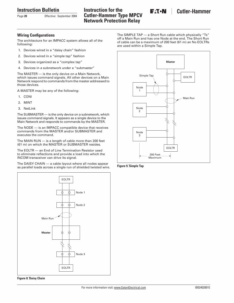
Wiring ConfigurationsThe architecture for an IMPACC system allows all of the following:
1. Devices wired in a “daisy chain” fashion
2. Devices wired in a “simple tap” fashion
3. Devices organized as a “complex tap”
4. Devices in a subnetwork under a “submaster”
The MASTER — is the only device on a Main Network, which issues command signals. All other devices on a Main Network respond to commands from the master addressed to those devices.
A MASTER may be any of the following:
1. CONI
2. MINT
3. NetLink
The SUBMASTER — is the only device on a subnetwork, which issues command signals. It appears as a single device to the Main Network and responds to commands by the MASTER.
The NODE — is an IMPACC compatible device that receives commands from the MASTER and/or SUBMASTER and executes the command.
The MAIN RUN — is a length of cable more than 200 feet (61 m) on which the MASTER or SUBMASTER resides.
The EOLTR — an End of Line Termination Resistor used to eliminate reflections and provide a load into which the INCOM transceiver can drive its signal.
The DAISY CHAIN — a cable layout where all nodes appear as parallel loads across a single run of shielded twisted wire.
Figure 8. Daisy Chain
The SIMPLE TAP — a Short Run cable which physically “Ts” off a Main Run and has one Node at the end. The Short Run of cable can be a maximum of 200 feet (61 m) an No EOLTRs are used within a Simple Tap.
Figure 9. Simple Tap
EOLTR
Node 1
Node 2
Node 3
EOLTR
Master
Main Run
Master
Node1
200 FeetMaximum
EOLTR
Main Run
EOLTRSimple Tap
Node2
Node3

IB02402001E For more information visit: www.EatonElectrical.com
Instruction BulletinEffective: September 2004 Page 21
Instruction for the Cutler-Hammer Type MPCVNetwork Protection Relay
The COMPLEX TAP — a Short Run cable which physically “Ts” off a Main Run and may have “sub Ts”. No EOLTRs are used within a Complex Tap.
Requirements:1. The total length of cable in the Complex Run must not
exceed 200 feet (61 m).
2. The total number of IMPACC devices must be equal or less than 64.
3. There are three levels of subtaps allowed with a restriction of 4 feet (1.2 m) on the third level.
Figure 10. Complex Tap
The MAIN NETWORK — consist of the Main Run connected to a MASTER as well as all the cabling in Simple Taps and Complex Taps connected to the Main Run.
The SUBNETWORK — consist of the Main Run connected to a SUBMASTER as well as all the cabling in Simple Taps and Complex Taps connected to the Main Run.
Figure 11. Main Network
Master
200 FeetMaximum
MainRun
EOLTR
Complex Tap
Node2
Node1
Node3
Node5
Node4
Node6
Node8
Node7
Level 3Sub-Tap
Level 1Sub-Tap
Level 2Sub-Tap
Node9
NodeN
EOLTR
Master
Main
Ru
n
EOLTR
Complex Tap
Node4
Node3
Node5
Daisy C
hain
EOLTR
EOLTR
EOLTR
NodeN
Sub-Network
Node1
Sub-Master
NodeN
Main Network
Main
Ru
n
No
de 1
No
de 2

For more information visit: www.EatonElectrical.com IB02402001E
Instruction BulletinPage 22 Effective: September 2004
Instruction for the Cutler-Hammer Type MPCVNetwork Protection Relay
The CABLE STAR — is created when the MASTER or SUBMASTER is connected to more than one Main Run.
Figure 12. Cable Star
The CABLE BRANCH — is created when splitting one or more Main Runs.
Figure 13. Cable Branch
Master
EOLTR
EOLTR
Simple TapMainRun
MainRun
EOLTR
EOLTR
Simple Tap
MainRun
MainRun
Node4
Node3
Node1
Node2
Node5
Node6
NodeN
Node7
EOLTR
Simple Tap
MainRun
MainRun
EOLTR
Simple Tap
MainRun
NodeN
Node3
Node4
Node2
Node1
200 Feet
200 Feet
Master
EOLTR

IB02402001E For more information visit: www.EatonElectrical.com
Instruction BulletinEffective: September 2004 Page 23
Instruction for the Cutler-Hammer Type MPCVNetwork Protection Relay
Installation RulesIn order to deliver a comprehensive and powerful energy management solution for use in electrical distribu-tion environments while ensuring affordability, flexibility, simplicity and noise immunity the following rules will allow the user to achieve the above advantages. These rules are expected to be followed as a starting point before troubleshooting is performed on a system.
1. Cable SelectionThe approved cable types are:
■ Any of the cable in the Belden 9463 family.■ IMPACABLE — a 600 volt rated custom designed for
IMPACC Style No. 2A95705G01.
2. Cable IntermixingAny of the above approved cables may be intermixed without compromising communication performance.
3. System Topology, Size and Capacity
Topology■ Bus or single star.■ Maximum number of long line from star: 5.■ No line termination for tap.■ Required EOLTR (100 ohms) at the end of long line.■ Maximum cable length between ends of longest lines:
10,000 feet (3,048 m)
Attenuation:■ Total system attenuation capacity: 25 dB.■ Attenuation per device: 0.01 dB.■ Attenuation of approved cables:
■ Attenuation at Star:
DefinitionSTAR — single point with a number of long lines emanating from it.
LONG LINE — greater than 200-foot (61 m) wire run.
4. Cable SplicingThe prime goal is to create a secure electrical connection while minimizing exposure to electrical transients.
■ Ferrules are used to dress cable ends in order to avoid problems associated with frayed and loose wires.
■ Use the device built-in two pole terminal blocks when splicing.
■ All devices, EOLTR, Simple Taps and Complex Taps should be placed in parallel across the cable.
5. Cable Shielding■ Cable shielding and outer jacket should not be stripped
longer than 1-1/2 inches (38.1 mm).■ Use the three pole terminal blocks at tap points to ensure
a continuous metallic shield ground path.■ Mechanically crimp sleeves on to the two-shield path
drain wires■ The cable shield ground path for a Main Network and
Subnetwork must not be joined together. Each should have a separate connection to earth ground reference.
6. Cable Grounding■ The shield ground path of a Main Network (and each
subnetwork) should be broken up into two separate isolated segments in such a way that a single, solid earth ground is available within 3,000 feet (914.4 m) of any point along the Main Network (or subnetwork).
■ Do not tie together drain wires of neighboring segments to achieve isolation.
■ Insulate unused drain wire to prevent accidental grounding.
■ Connect the shield ground path’s drain wire to a #14 AWG or larger multi-stranded wire that has an impedance path of 1 ohm or less to a known earth ground. Note that a new ground path will be required when the shield ground travel through many connections and considerable distances before reaching earth ground.
7. Cable TerminationThe Main Runs of the Main network and each Subnetwork require a pair of EOLTR, rated 100 ohms, _ watt carbon or metal film resistors. Do not use wirewound resistors.
■ The resistors should be placed in parallel across the splicing junction servicing the Complex Tap rather than at the far end within the Complex Tap.
■ Tap off from the Main Runs do not require EOLTR.
8. Device AddressTo avoid the possibility of devices in a Main Network having the same address as those in Subnetworks, set the Main Network device addresses to start at 100 or higher excluding 901 to 908.
Cable Type Attenuation per 1,000 ft. (304.8 m)
IMPACABLEBelden 9463
1.6 dB2.0 dB
No. of Long Lines Attenuation
345
3.5 dB6.0 dB8.0 dB

For more information visit: www.EatonElectrical.com IB02402001E
Instruction BulletinPage 24 Effective: September 2004
Instruction for the Cutler-Hammer Type MPCVNetwork Protection Relay
PowerNet Reason Descriptions on MPCV Relay StatusTable 7 provides descriptions of all of the possible Status and Reason states as reported by the MPCV Relay via Pow-erNet. Note that the status is a function of the Aux_B input contact to the MPCV in combination with any Trip or Close control from the MPCV and time. The first column shows network protector status based on the AUX B input contact, where “C” denotes the network protector is sensed to be CLOSED (physical Aux B contact is open). Similarly, an “O” indicates an OPEN protector (Aux B contact is closed).
It indicates that all of the following TRIP descriptions imply that the network protector has been sensed to be OPEN, prior to which a protective TRIP control was issued to the protector by the MPCV. The associated PowerNet Reason String attempts to detail what power system condition caused the MPCV to command a trip. The descriptions provided for the Trip states are also applicable for Time-Stamped Trip Events.
Note: Alarm Status has higher priority than Trip, Open or Close in Table 7 below.
Table 7. PowerNet Reason Descriptions on MPCV Relay StatusNWP Status
RelayStatus
Reason Description
C Closed Normal Sensed in the CLOSED position, Normal
O Open Normal Sensed in the OPEN position, Normal
O Open Remote OpenBlock Open
Sensed in the OPEN position, and MPCV was Remotely commanded to be Open/ Blocked Open (ROBO)
O Trip Phase Reversal Typically indicative of a reversed phase condition on the network side. An improper CBA rotation set point will also generate this reason. Bus voltages and the bus connections to the MPCV should also be verified.
O Trip Rolled Phase Typically indicative of a rolled phased power system condition. Bus voltages and the bus connections to the MPCV should also be verified.
O Trip Per Unit Voltage
Indicative of a reversed phase condition on the transformer, or a rolled phase on the transformer, or a rolled phase on the network. Bus voltages and the bus connections to the MPCV should also be verified.
O Trip Sensitive Reverse current exceeded RT set point for at least 2 power cycles (instantaneous), Watt Trip characteristic (WV=OFF), TD=0.
O Trip Time Delayed Sensitive
Reverse current exceeded RT set point for the duration of the non-zero TD setting, Watt Trip characteristic (WV=OFF).
O Trip De-energized The magnitudes of the positive sequence network voltage AND the positive sequence phasing voltage indicates a de-energized network and feeder system condition. Bus voltages and the bus connections to the MPCV should be verified.
O Trip Var Trip Reverse current exceeded RT set point for at least 2 power cycles (instantaneous), Watt-Var Trip characteristic (WV=ON), TD=0, and the reverse current phasor fell in the var region (60 degree portion) of the overall Watt-Var Trip curve.
O Trip BreakerPumping
Pump Protection is enabled, and the protector has cycled the programmed number of cycles within the pump time setting. The MPCV will continue to command a TRIP to protector, until expiration of the Reset Timer or a Remote command to clear the pumping fault.
O Trip Overcurrent Reverse current exceeded OC set point for at least 2 power cycles, Watt Trip characteristic (WV=OFF). Overcurrent OC is strictly an “instantaneous” setting.
O Trip Non-Sensitive Technically refers to the “Sensitive Plus Non-Sensitive” trip mode of the MPCV Relay. This mode is selected by setting TD=0, and OC>0, resulting in a trip characteristic with an intentional non-trip dead band region. This mode is NOT recommended for most applications.
O Trip Watt Trip Reverse current exceeded RT set point for at least 2 power cycles (instantaneous), Watt-Var Trip characteristic (WV=ON), TD=0, and the reverse current phasor fell in the Watt region (-5 deg portion) of the overall Watt-Var Trip curve.
O Trip Time DelayedWatt Trip
Reverse current exceeded RT set point for the duration of the non-zero TD setting, Watt-Var Trip characteristic (WV=ON).
O Trip OvercurrentWatt Trip
Reverse current exceeded OC set point for at least 2 power cycles, Watt-Var Trip characteristic (WV=ON). Overcurrent OC is strictly an “instantaneous” setting.
O Trip Set Point MPCV has detected a checksum problem with the programmed set points in non-volatile memory. Protector will trip and relay should be replaced.
O Trip RAM MPCV has detected a RAM memory problem on power-up. Protector will trip (for CH FW version V.1.016 and GE FW version V1.017 or newer) and relay should be replaced.
(C) Alarm Failed to Open MPCV has tried to TRIP the protector, but did NOT sense that the Aux B input contact closed within 10 seconds. May be a problem in the protector trip circuit or wiring of the Aux B contact.
(O) Alarm Failed to Close MPCV has tried to CLOSE the protector, but did NOT sense that the Aux B input contact opened within 10 seconds. May be a problem in the protector close circuitry or wiring of the Aux B contact
? Alarm Auxiliary 2Alarm
Auxiliary Channel 2 has been activated, has been set to alarm on activation, and the channel is currently in the active state.
? Alarm Auxiliary 3Alarm
Auxiliary Channel 3, as Aux 2 above.
? Alarm Auxiliary 4Alarm
Auxiliary Channel 4, as Aux 2 above.
? ? Not responding Possible loss of power, communication error, the relay is out of service or the wiring has been compromised.

IB02402001E For more information visit: www.EatonElectrical.com
Instruction BulletinEffective: September 2004 Page 25
Instruction for the Cutler-Hammer Type MPCVNetwork Protection Relay
Relay Replacement GuidelinesThe MPCV Relay is designed as a direct replacement for the EMMR (Electromechanical Master Relay), EMPR (Electro-mechanical Phasing Relay), SSNPR (Solid-State Network
Protector Relay), DNPR (Digital Network Protector Relay), MPCR (Microprocessor Network Protector Relay) relays without wiring modifications on the protector. Additional wirings are needed from the “b” contact of the protector to Aux –1 (points 7 and 8) of the relay when communications are used or when anti-pumping feature is activated.
A network protector manufactured by Eaton, Richards or GE can use the MPCV Relay without any wiring modifications. There are five different relay styles that can be used to match any protector style. The protective and safety features of the relay are still operational when used with other protectors made by other manufacturers.
1. MPCV-D (216 V) Style# 6417C82G01
2. MPCV-22 (216 V) Style# 6417C83G01
3. MPCV-2X (216 V) Style# 6417C83G03
4. MPCV-GE (216 V) Style# 6417C84G014
5. MPCV-P (216 V) Style# NAS0129G01
Kits include Relay, CNJ Jumper Plate, Wiring Kit and Instruction Book unless otherwise noted.
Table 8. MPCV-D (216 V) — Relay # 6417C82G01 — Kit # 8231A80G05For use in CMD Network Protectors having GRD-Y connected CTs. Relay will replace:
Table 9. MPCV-22 (216 V) — Relay # 6417C83G01 — Kit # 8231A80G08For use in CM-22 and CMR-8 Network Protectors having energized CTs. Relay will replace:
Table 10. MPCV-2X (216 V) — Relay # 6417C83G03 — Kit # 8231A80G03For use in CM-22 and CMR-8 Network Protectors having GRD-Y connected CTs. Relay will replace:
Note: Kit # 8231A80G07 is available for converting from 480 V Electromechanical Relays and includes the relay, CNJ Jumper Plate, Wiring Kit, Instruction Book, and 3-Phase Potential Transformer.
Note: Units with energized CTs can be changed to GRD-Y connected CTs based on instructions noted in Relay Conversion Guidelines on Page 26.
Table 11. MPCV-GE (216 V) — Relay # 6417C84G01 — Kit # 8231A80G06For use in GE MG-8, MG-9, MG14 and MG-14A Network Protectors using electromechanical Type CAN or CHN master and Type CAL or CHL phasing relays. Will also replace any GE network breaker wired for the solid-state analog type SSNPR relay. Relay will replace:
Table 12. MPCV-P (216 V) — Relay # NAS0129G01For use in MV Substation Breaker control. Wires are termi-nated in a two 9-pin terminal block. Relay will replace:Relay Style Number Description
CN-33MPCR-D Phase 4MPCR-D Phase 5
691B509A108312A12G018313A13G01
Wiring Modifications per IB 35-581BNo Wiring Modifications RequiredNo Wiring Modifications Required
SSNPR (Tempo)DNPR (Tempo)
651507DW-CMD64747D1000-5
No Wiring Modifications RequiredNo Wiring Modifications Required
Relay Style Number Description
CN-33 SSNPR (Tempo)DNPR (Tempo)
937184 or 1727403651507DW-CM22M 64747D1000-4
No Wiring Modifications RequiredNo Wiring Modifications RequiredNo Wiring Modifications Required
Relay Style Number Description
CN-33 Var 289B958A16 or 691B509A09
Also Requires 2 Relay Studs Style# 1043741 to Replace the E/M Relay Studs and CT Wiring Change to Watt Connection (13 to A, 23 to B, 33 to C)
MPCR-22 Phase 4MPCR-22 Phase 5
8314A14G018313A14G01
No Wiring Modifications RequiredNo Wiring Modifications Required
SSNPR (Tempo)DNPR (Tempo)
651507DW-CM2264747D1000-3
No Wiring Modifications RequiredNo Wiring Modifications Required
Relay Style Number Description
SSNPR (Tempo)DNPR (Tempo)
651507DGE-1 or -264747D1000-2
No Wiring Modifications RequiredNo Wiring Modifications Required
Relay Style Number Description
SSNPR (Tempo)DNPR (Tempo)
65196264747D1000-7
No Wiring Modifications RequiredNo Wiring Modifications Required

For more information visit: www.EatonElectrical.com IB02402001E
Instruction BulletinPage 26 Effective: September 2004
Instruction for the Cutler-Hammer Type MPCVNetwork Protection Relay
Relay Conversion Guidelines1. CNJ relay should be replaced with the CNJ dummy
plate Style No. 508B559G01.
2. BN Relay (if present) should be replaced with either a BN dummy plate Style No. 435D857G03 or BN Jack Plate Style No. 435D857G04. In the event that there is already a BN Dummy or Jack Plate present — DO NOT remove the plate.
3. The Aux 1 points 7 and 8 of the AUX I/O ports — need a breaker “b” contact (NC) input connected for communi-cations and the anti-pumping feature. This contact input gives the relay the status of the network protector — open or close. This wiring change is recommended but not required unless communications and anti-pumping features are required.
4. Additional wiring changes and components are required for 480 and 600 volt units. The MPCV Relay is designed to function at 125 volts Line-to-Ground.
Energized to GRD-Y Current Transformer Rewiring (216Y/125)A. To permit the relay to function properly requires that the
energized CTs be changed to a GRD-Y connected scheme.
B. Remove the leads from the transformer side bus con-nection to the CT.
C. Connect the three loose leads from the CTs together and splice them with two additional lengths of AWG-16 TeflonT coated wire. One wire should go to GROUND and the other wire should be connected to terminal 5 on the relay connector.
Note: If the relay responds during test in a close mode at 180 degrees (reverse current) or a trip mode in phase or at 60 degrees, then the CTs are connected in reverse polarity. Reverse the CT connections on all three phases to correct this situation.
Energized to GRD-Y Current Transformer Rewiring (480Y/277)A. To permit the relay to function properly requires that the
energized CTs be changed to a GRD-Y connected scheme.
B. Remove leads 12, 22 and 32 from the CT and insulate the free-end of the wire. If two or more wires are connected at the same point, remove all of them and connect them together. Insulate the connection.
C. Connect the CTs together and splice them with two addi-tional lengths of AWG-16 Teflon coated wire. One wire should go to GROUND and the other wire should be connected to terminal 5 on the relay connector.
Note: If the relay responds during test in a close mode at 180 degrees (reverse current) or a trip mode in phase or at 60 degrees, then the CTs are connected in reverse polarity. Reverse the CT connections on all three phases to correct this situation.
D. Wires T2 and T3 connected at the potential transformers must be on tap “B” and not tap “C.” If electromechanical relays are to be re-installed, these two leads must be reconnected to tap “C.”
Note: If the network protector is wired for an electromechanical watt-var relay, the wiring must be changed over to the watt trip characteristic. The MPCV can be set for a watt-var trip characteristic even though the input is connected as a watt characteristic.

IB02402001E For more information visit: www.EatonElectrical.com
Instruction BulletinEffective: September 2004 Page 27
Instruction for the Cutler-Hammer Type MPCVNetwork Protection Relay
Curve Drawings
Figure 14. Straight Closing Curve
Phasing Line
ML
0
27090
180
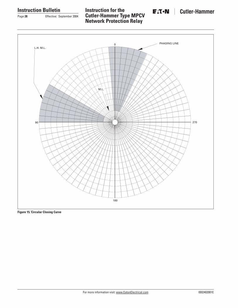
For more information visit: www.EatonElectrical.com IB02402001E
Instruction BulletinPage 28 Effective: September 2004
Instruction for the Cutler-Hammer Type MPCVNetwork Protection Relay
Figure 15. Circular Closing Curve
L.H. M.L.
PHASING LINE0
27090
180
M.L.

IB02402001E For more information visit: www.EatonElectrical.com
Instruction BulletinEffective: September 2004 Page 29
Instruction for the Cutler-Hammer Type MPCVNetwork Protection Relay
Figure 16. Reverse Trip — Sensitive Curve
Gull-wing TripThe new trip characteristic referred to as the “Gull-wing” watt trip is repre-sented by a broken line with a 5 degree slope towards the 90 degree line, while the solid line represents the traditional watt trip characteristic of Network Protector Relays, including earlier versions of the MPCV Relay.
The “Gull-wing” watt trip widens the trip region by additional 10 degrees to compensate for CT phase angle error during fault conditions and high trans-former X to R ratios, allowing the relay to trip whenever the positive-sequence component of the current leads the positive-sequence line-to-ground volt-
age by more than 85 degrees. In com-parison, the traditional watt trip characteristic would allow closure only if this angle is more than 95 degrees. With this additional trip region, the relay will dependably detect the simul-taneous fault and blown fuse condi-tions that would not be detected by the traditional watt trip.
Note that the MPCV-GE provides a similar functionality, but the slope of it's expanded tilt region is 0 degrees parallel to the 90 degree line due to the nature of the GE tertiary current trans-former.
A – “Gull-wing” trip line for Cutler-Hammer style relay firmware version V1.014 and for GE style relay firmware version V1.015.
0
27090
180
A

For more information visit: www.EatonElectrical.com IB02402001E
Instruction BulletinPage 30 Effective: September 2004
Instruction for the Cutler-Hammer Type MPCVNetwork Protection Relay
Figure 17. Watt Trip with Non-Sensitive Range
0
27090
180
A

IB02402001E For more information visit: www.EatonElectrical.com
Instruction BulletinEffective: September 2004 Page 31
Instruction for the Cutler-Hammer Type MPCVNetwork Protection Relay
Figure 18. Watt-Var with Non-Sensitive Trip
Non-Sensitive Trip Region
WV
0
27090
180

Instruction BulletinPage 32 Effective: September 2004
Instruction for the Cutler-Hammer Type MPCVNetwork Protection Relay
© 2004 Eaton CorporationAll Rights ReservedPrinted in USAPublication No. IB02402001E / Z2463September 2004
Cutler-Hammer is a federally registered trademark of Eaton Corporation. General Elec-tric is a federally registered trademark of General Electric Company. Teflon is a regis-tered trademark of E.I. DuPont de Nemours and Company. Microsoft and Windows are registered trademarks of Microsoft Corporation. National Electrical Code and NEC are registered trademarks of the National Fire Protection Association, Quincy, Mass. CSA is a registered trademark of the Canadian Standards Association. IBM is a registered trademark of International Business Machines, Inc. Phoenix is a registered trademark of Phoenix of Chicago, Inc. Westinghouse is a registered trademark of Westinghouse Electric Company LLC.
Eaton Electrical Inc.1000 Cherrington ParkwayMoon Township, PA 15108-4312USAtel: 1-800-525-2000www.EatonElectrical.com