Instruction book IQAN-MC2 - · PDF fileunits XA2, XS2, XT2, Lx and XR. By supporting SAE J1939...
37
Instruction book IQAN-MC2 Publ no HY17-8388-IB/UK Edition October, 2008 ®
Transcript of Instruction book IQAN-MC2 - · PDF fileunits XA2, XS2, XT2, Lx and XR. By supporting SAE J1939...

Instruction bookIQAN-MC2Publ no HY17-8388-IB/UKEdition October, 2008
®
II
Contents
Instruction book, IQAN-MC2
1 Introduction . . . . . . . . . . . . . . . . . . . . . . . . . . . . . . . . . . . . . . . . . . . . . . . . . . . . . . . . . . . . . . .1
2 Precautions . . . . . . . . . . . . . . . . . . . . . . . . . . . . . . . . . . . . . . . . . . . . . . . . . . . . . . . . . . . . . . . . 2General safety regulations . . . . . . . . . . . . . . . . . . . . . . . . . . . . . . . . . . . . . . . . . . . . . . . . . . . . . 2
3 Product description . . . . . . . . . . . . . . . . . . . . . . . . . . . . . . . . . . . . . . . . . . . . . . . . . . . . . . . . 4IQAN-MC2 . . . . . . . . . . . . . . . . . . . . . . . . . . . . . . . . . . . . . . . . . . . . . . . . . . . . . . . . . . . . . . . . . . . . . 4
4 Safety . . . . . . . . . . . . . . . . . . . . . . . . . . . . . . . . . . . . . . . . . . . . . . . . . . . . . . . . . . . . . . . . . . . . .7General . . . . . . . . . . . . . . . . . . . . . . . . . . . . . . . . . . . . . . . . . . . . . . . . . . . . . . . . . . . . . . . . . . . . . . . . 7
System Diagnostics . . . . . . . . . . . . . . . . . . . . . . . . . . . . . . . . . . . . . . . . . . . . . . . . . . . . . . . . . . . . 8
5 Mounting . . . . . . . . . . . . . . . . . . . . . . . . . . . . . . . . . . . . . . . . . . . . . . . . . . . . . . . . . . . . . . . . . .9Mounting the module . . . . . . . . . . . . . . . . . . . . . . . . . . . . . . . . . . . . . . . . . . . . . . . . . . . . . . . . . 9
6 Installation . . . . . . . . . . . . . . . . . . . . . . . . . . . . . . . . . . . . . . . . . . . . . . . . . . . . . . . . . . . . . . 10Supply voltage . . . . . . . . . . . . . . . . . . . . . . . . . . . . . . . . . . . . . . . . . . . . . . . . . . . . . . . . . . . . . . . 12
IQAN-MC2 addressing/terminating . . . . . . . . . . . . . . . . . . . . . . . . . . . . . . . . . . . . . . . . . . . . 14
USB connection . . . . . . . . . . . . . . . . . . . . . . . . . . . . . . . . . . . . . . . . . . . . . . . . . . . . . . . . . . . . . . . 16
Reference voltage, VREF . . . . . . . . . . . . . . . . . . . . . . . . . . . . . . . . . . . . . . . . . . . . . . . . . . . . . . 17
Voltage inputs . . . . . . . . . . . . . . . . . . . . . . . . . . . . . . . . . . . . . . . . . . . . . . . . . . . . . . . . . . . . . . . . 18
Frequency inputs . . . . . . . . . . . . . . . . . . . . . . . . . . . . . . . . . . . . . . . . . . . . . . . . . . . . . . . . . . . . . 22
Proportional outputs . . . . . . . . . . . . . . . . . . . . . . . . . . . . . . . . . . . . . . . . . . . . . . . . . . . . . . . . . . 23
Connecting loads to proportional outputs . . . . . . . . . . . . . . . . . . . . . . . . . . . . . . . . . . . . . 24
Digital outputs . . . . . . . . . . . . . . . . . . . . . . . . . . . . . . . . . . . . . . . . . . . . . . . . . . . . . . . . . . . . . . . 25
Low-side digital outputs . . . . . . . . . . . . . . . . . . . . . . . . . . . . . . . . . . . . . . . . . . . . . . . . . . . . . . 26
7 Start-up . . . . . . . . . . . . . . . . . . . . . . . . . . . . . . . . . . . . . . . . . . . . . . . . . . . . . . . . . . . . . . . . . 27Start-up procedures . . . . . . . . . . . . . . . . . . . . . . . . . . . . . . . . . . . . . . . . . . . . . . . . . . . . . . . . . . 27
Appendix A . . . . . . . . . . . . . . . . . . . . . . . . . . . . . . . . . . . . . . . . . . . . . . . . . . . . . . . . . . . . . . 29Appendix B . . . . . . . . . . . . . . . . . . . . . . . . . . . . . . . . . . . . . . . . . . . . . . . . . . . . . . . . . . . . . . 33
Error codes, messages and actions . . . . . . . . . . . . . . . . . . . . . . . . . . . . . . . . . . . . . . . . . . . . 33Appendix C . . . . . . . . . . . . . . . . . . . . . . . . . . . . . . . . . . . . . . . . . . . . . . . . . . . . . . . . . . . . . . 34
Dimensioning of the IQAN-MC2 module . . . . . . . . . . . . . . . . . . . . . . . . . . . . . . . . . . . . . . . 34

Safety symbols1 Introduction
1 Introduction
These instructions are to be used as a reference tool for the vehicle manufacturer’s design, production, and service personnel.
The user of these instructions should have basic knowledge in the handling of electronic equipment.
Safety symbolsSections regarding safety, marked with a symbol in the left margin, must be read and understood by everyone using the system, carrying out service work or making changes to hardware and software.
The different safety levels used in this manual are defined below.
WARNING
Sections marked with a warning symbol in the left margin, indicate that a hazardous situation exists. If precautions are not taken, this could result in death, serious injury or major property damage.
CAUTION
Sections marked with a caution symbol in the left margin, indicate that a potentially hazardous situation exists. If precautions are not taken, this could result in minor injury or property damage.
NOTICE
Sections marked with a notice symbol in the left margin, indicate there is important information about the product. Ignoring this could result in damage to the product.
Contact the manufacturer if there is anything you are not sure about or if you have any questions regarding the product and its handling or maintenance.
The term "manufacturer" refers to Parker Hannifin Corporation.
1Instruction book, IQAN- MC2

General safety regulations2 Precautions
2 Precautions
General safety regulationsWork on the hydraulics control electronics may only be carried out by trained personnel who are well-acquainted with the control system, the machine and its safety regulations.
WARNING
Mounting, modification, repair and maintenance must be carried out in accordance with the manufacturer's regulations. The manufacturer has no responsibility for any accidents caused by incorrectly mounted or incorrectly maintained equipment. The manufacturer does not assume any responsibility for the system being incorrectly applied, or the system being programmed in a manner that jeopardizes safety.
WARNING
Damaged product may not be used. If the control system shows error functions or if electronic modules, cabling or connectors are damaged, the system shall not be used.
WARNING
Electronic control systems in an inappropriate installation and in combination with strong electromagnetic interference fields can, in extreme cases, cause an unintentional change of speed of the output function.
NOTICE
As much as possible of the welding work on the chassis should be done before the installation of the system. If welding has to be done afterwards, the electrical connections on the system must be disconnected from other equipment. The negative cable must always be disconnected from the battery before disconnecting the positive cable. The ground wire of the welder shall be positioned as close as possible to the place of the welding. The cables on the welding unit shall never be placed near the electrical wires of the control system.
Construction regulations
CAUTION
The vehicle must be equipped with an emergency stop which disconnects the supply voltage to the control system's electrical units. The emergency stop must be easily accessible to the operator. The machine must be built if possible, so that the supply voltage to the control system's electrical units is disconnected when the operator leaves the operator’s station.
Safety during installation
CAUTION
Incorrectly positioned or mounted cabling can be influenced by radio signals which can interfere with the functions of the system.
2Instruction book, IQAN- MC2
General safety regulations2 Precautions
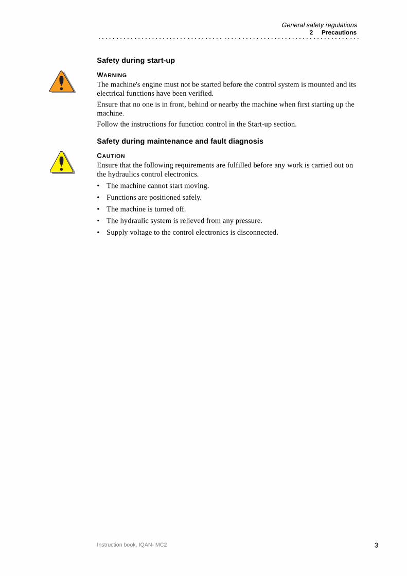
Safety during start-up
WARNING
The machine's engine must not be started before the control system is mounted and its electrical functions have been verified.
Ensure that no one is in front, behind or nearby the machine when first starting up the machine.
Follow the instructions for function control in the Start-up section.
Safety during maintenance and fault diagnosis
CAUTION
Ensure that the following requirements are fulfilled before any work is carried out on the hydraulics control electronics.
• The machine cannot start moving.
• Functions are positioned safely.
• The machine is turned off.
• The hydraulic system is relieved from any pressure.
• Supply voltage to the control electronics is disconnected.
3Instruction book, IQAN- MC2

IQAN-MC23 Product description
3 Product description
IQAN-MC2The IQAN-MC2 is designed for controlling hydraulic systems in vehicles and machinery, using 12/24 Vdc power supply.
IQAN-MC2 is a master unit capable of running applications created by IQANdesign. The MC2 has local I/O for input/output use and has two CAN busses that support ICP (IQAN CAN Protocol), SAE J1939 and Generic CAN. As a bus master the MC2 is able to control expansions units XA2, XS2, XT2, Lx and XR.
By supporting SAE J1939 and Generic CAN the MC2 can act as a sub-master when there is a need of higher performance in a sub-circuit or when there is an OEM supplied overall machine master.
This product is designed for the outdoor environment and comes with an IP6K9K protection for applications where high-pressure water and steam jet cleaning is used.
The IQAN-MC2 module.
I/O overview
+BAT ADDR-H
ADDR-L
CAN-H
CAN-L
PORT 1
-BAT
+VREF
-VREF
USB
MC2 CAN-H
CAN-L
PORT 0
4Instruction book, IQAN- MC2

IQAN-MC23 Product description
InputsThe IQAN-MC2 module has eight (5) voltage inputs VIN-A thru VIN-E for connection of 0-5 Vdc signals. The inputs are multi-purpose and for flexibility may be configured in other ways. The input pins VIN-A and VIN-E can be configured as on/off inputs for switches or as frequency inputs for measuring frequency. Voltage inputs, on/off inputs and frequency inputs share positions, see list.
Proportional outputsThe MC2 module has eight (8) double proportional outputs for controlling proportional valves. These outputs can control eight bi-directional valve sections or eight single solenoid devices (ie. proportional cartridge valves). The proportional outputs can be used in two different modes. Either Current mode (current closed loop) or PWM mode (voltage open loop) signals can be selected and the parameters configured using IQAN software.
For flexibility these outputs may also be configured as up to eight (8) on/off outputs and up to eight (8) on/off inputs or voltage inputs. Additional functionality for these positions is as up to sixteen (16 ) low-side on/off outputs. The proportional outputs, on/off outputs, on/off or voltage inputs and low-side on/off outputs share positions, see below.
In order to increase the performance of the proportional outputs when controlling proportional valves, the dither frequency can be adjusted.
(5) Voltage inputs VIN-A thru VIN-E
or
(5) Frequency inputs FIN-A thru FIN-E use positions VIN-A thru VIN-E.
or
(5) Digital inputs DIN-A thru DIN-E use positions VIN-A thru VIN-E.
(8) double proportional outputs COUT-A thru COUT-H
or
(8) double proportional outputs PWMOUT-A thru PWMOUT-H
or
(8) on/off outputs DOUT-A thru DOUT-H.Each pair of return pins may then be used as:(2) low-side digital output switches (16) total, DOUT(LS)-I thru DOUT(LS)-X.
It is recommended to use one or more of DOUT-A thru DOUT-H as source if used in this manner, for safety.The pairs of return pins associated with DOUT-E thru DOUT-H may also be used as:(2) on/off inputs, (8) total, DIN-F thru DIN-M.(2) voltage inputs, (8) total, VIN-F thru VIN-M.
5Instruction book, IQAN- MC2

IQAN-MC23 Product description
CAN related functionsThe MC2 uses the CAN-bus (CAN = Controller Area Network) to communicate with the modules. The CAN-bus is a robust communication protocol that is widely used and well proven within the automotive industry.
CommunicationThe communication interface is used for uploading/downloading applications or
diagnostics and typically are connected to a computer.
USBThe IQAN-MC2 has a USB1.1 (device only) connection in connector C1.
6Instruction book, IQAN- MC2
General4 Safety
4 Safety
GeneralIn order to fulfill the highest safety demands, the MC2 module uses a real-time operating system for fault tolerant embedded systems. The MC2 module has an internal watchdog function. If the RTOS (real time operating system) detects any software errors, necessary precautions will be activated and the watchdog will reset the module.
Polarity reversalThe MC2 module is protected against power supply polarity reversal and over-voltage, provided an external fuse, max 20 A (Fast) is being used.If this fuse is not used, polarity reversal can damage the unit.
CAN-bus interruptionThe MC2 module has special safety functions if the CAN-bus is interrupted. Each module checks for any interruptions in the CAN-bus communication. If an error occurs the master unit’s LED will show an appropriate error code ref, section System Diagnostics, on page 8.
Input/ output ProtectionAll inputs on the MC2 module are designed to withstand the maximum specified supply voltage. The outputs are protected against short circuit. Furthermore, an error on one input/output will not influence other inputs/outputs.
Current checkFor the proportional outputs when used in current mode, a current check is performed. If an error occurs the master unit’s LED will show an appropriate error code ref, section System Diagnostics, on page 8.
The MC2 module can detect open-circuit, short-circuit to +BAT/-BAT or short-circuit to other proportional output and return pins. In these cases the module will shut off the affected output in order to increase safety.
Built-in testThe MC2 module will execute a self-test during operation to verify the hardware and the software.
The test includes CAN- bus verification, memory integrity check and an internal signal verification. If any error is detected appropriate precautions will be activated.
7Instruction book, IQAN- MC2

System Diagnostics4 Safety
System DiagnosticsThe yellow blinking LED on the top of the module indicates normal status. If there is an error detected, the master will present a message on the display. The MC2 module also indicates error status through the red blinking LED.This gives an immediate diagnosis as to the nature of the error that has occurred.
The location of the LED indicators on the IQAN-MC2 module.
The green LED indicates power on. The yellow/red LED, will be blinking red when an error has been detected. To get futher information about the error messages, see Appendix B, on page 33
A small recommendation...You can use the internal diagnostics in the master to get more information about the MC2 module. The following values are supervised:
Internal temperature [°C]
Power supply [V]
Reference voltage [V]
Green, power on
Yellow/ red, status
8Instruction book, IQAN- MC2

Mounting the module5 Mounting
5 Mounting
Mounting the moduleThe IQAN-MC2 module should be mounted according to the following instructions:
• Locate the module eliminating the risk for the cabling to be folded, crushed or damaged in any way. Ensure the cabling cannot pull, twist or induce sideload on the connector.
• Locate the module so that severe physical impact is avoided, e.g impact from falling objects or the module being used as a step.
• Locate the module so that air can circulat to eliminate excess heat. Ensure that no external heat, e.g. from the engine or heater, is transferred to the module.
• Locate the module to protect it from high pressure washing or similar.
• Locate the module so that the cable connector is facing down .
• Locate the module so that the LEDs are visible.
Non approved placing.
NOTICE
The IQAN-MC2 module must not be placed in any marine related or similar continuously damp, salt-spray environment without external protection.
Assembling of the ID-TagThe ID-Tag will be placed in the connector in order to address/ terminate the module, ref section IQAN-MC2 addressing/terminating, on page 14.The ID-Tag will be mounted under the connector casing. Bend the ID-Tag’s wires toward the opposite side of where the other wires enter the connector.
Assembling of the Id-Tag.
9Instruction book, IQAN- MC2
Mounting the module6 Installation
6 Installation
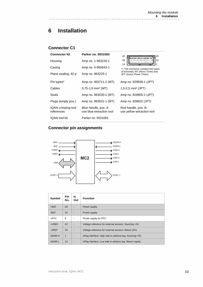
Connector C1
Connector pin assignments
Connector kit Parker no. 5031063
Housing Amp no. 1-963226-1
Casing Amp no. 0-965643-1
Plane sealing, 42 p Amp no. 963225-1
Pin types* Amp no. 963711-2 (MT) Amp no. 929938-1 (JPT)
Cables 0,75-1,0 mm² (MT) 1,5-2,5 mm² (JPT)
Seals Amp no. 963530-1 (MT) Amp no. 828905-1 (JPT)
Plugs (empty pos.) Amp no. 963531-1 (MT) Amp no. 828922 (JPT)
IQAN crimping tool references
Blue handle, pos. Ause blue extraction tool
Red handle, pos. Buse yellow extraction tool
IQAN tool kit Parker no. 5031061
SymbolPin No.
InOut
Function
+BAT 28 - Power supply
-BAT 15 - Power supply
+RTC 6 - Power supply for RTC.
+VREF 42 - Voltage reference for external sensors. Sourcing +5V.
-VREF 29 - Voltage reference for external sensors. Return (0V).
ADDR-H 1 - IdTag interface. High side to address tag. Sourcing +5V.
ADDR-L 14 - IdTag interface. Low side to address tag. Return signal.
*= The connector contains two types of terminals; MT (Micro Timer) and JPT (Junior Power Timer).
42
28
14
29
15
1
+BAT ADDR-H
ADDR-L
CAN-H
CAN-L
PORT 1
-BAT
+VREF
-VREF
USB
MC2 CAN-H
CAN-L
PORT 0
10Instruction book, IQAN- MC2
Mounting the module6 Installation
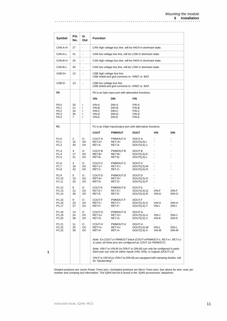
Shaded positions are Junior Power Timer pins. Unshaded positions are Micro Timer pins. See above for wire, seal, pin number and crimping tool information. The IQAN tool kit is found in the ’IQAN accessories’ datasheet.
CAN-A-H 27 - CAN high voltage bus line, will be HIGH in dominant state.
CAN-A-L 41 - CAN low voltage bus line, will be LOW in dominant state.
CAN-B-H 26 - CAN high voltage bus line, will be HIGH in dominant state.
CAN-B-L 40 - CAN low voltage bus line, will be LOW in dominant state.
USB-D+ 12 - USB high voltage bus line.USB shield and gnd connects to -VREF or -BAT.
USB-D- 13 - USB low voltage bus line.USB shield and gnd connects to -VREF or -BAT.
P0
P0.0P0.1P0.2P0.3P0.4
202134357
IIIII
P0 is an 5pin input port with alternative functions.
VIN DIN FIN
VIN-A DIN-A FIN-AVIN-B DIN-B FIN-BVIN-C DIN-C FIN-CVIN-D DIN-D FIN-DVIN-E DIN-E FIN-E
P1
P1.0P1.1P1.2
P1.3P1.4P1.5
P1.6P1.7P1.8
P1.9P1.10P1.11
P1.12P1.13P1.14
P1.15P1.16P1.17
P1.18P1.19P1.20
P1.21P1.22P1.23
21630
31731
41832
51933
82236
92337
102438
112539
OO/IO/I
OO/IO/I
OO/IO/I
OO/IO/I
OO/IO/I
OO/IO/I
OO/IO/I
OO/IO/I
P1 is an 24pin input/output port with alternative functions.
COUT PWMOUT DOUT VIN DIN
COUT-A PWMOUT-A DOUT-A - -RET-A+ RET-A+ DOUT(LS)-I - -RET-A- RET-A- DOUT(LS)-J - -
COUT-B PWMOUT-B DOUT-B - -RET-B+ RET-B+ DOUT(LS)-K - -RET-B- RET-B- DOUT(LS)-L - -
COUT-C PWMOUT-C DOUT-C - -RET-C+ RET-C+ DOUT(LS)-M - -RET-C- RET-C- DOUT(LS)-N - -
COUT-D PWMOUT-D DOUT-D - -RET-D+ RET-D+ DOUT(LS)-O - -RET-D- RET-D- DOUT(LS)-P - -
COUT-E PWMOUT-E DOUT-E - -RET-E+ RET-E+ DOUT(LS)-Q VIN-F DIN-FRET-E- RET-E- DOUT(LS)-R VIN-G DIN-G
COUT-F PWMOUT-F DOUT-F - -RET-F+ RET-F+ DOUT(LS)-S VIN-H DIN-HRET-F- RET-F- DOUT(LS)-T VIN-I DIN-I
COUT-G PWMOUT-G DOUT-G - -RET-G+ RET-G+ DOUT(LS)-U VIN-J DIN-JRET-G- RET-G- DOUT(LS)-V VIN-K DIN-K
COUT-H PWMOUT-H DOUT-H - -RET-H+ RET-H+ DOUT(LS)-W VIN-L DIN-LRET-H- RET-H- DOUT(LS)-X VIN-M DIN-M
Note: If a COUT or PWMOUT block (COUT-x/PWMOUT-x, RET-x+, RET-x-) is used, all three pins are configured as COUT (or PWMOUT).
Note: VIN-F to VIN-M (or DIN-F to DIN-M) can only be configured in pairs.Each pair can only be either inputs (VIN, DIN), or outputs (DOUT-LS)
VIN-F to VIN-M (or DIN-F to DIN-M) are equipped with clamping diodes, risk for “backending”.
SymbolPin No.
InOut
Function
11Instruction book, IQAN- MC2

Supply voltage6 Installation
Supply voltageBefore any installation of the IQAN system can take place, make sure the ignition lock is turned off and the battery is disconnected.
Emergency stopMake sure an Emergency Stop disconnecting the power supply, is easily accessible at any time. Further relevant regulations are to be found in Machinery Directives 9837/EC. The figure below shows how to connect the emergency stop.
Connecting of Supply VoltageThe supply voltage, should be within the operating interval, see Appendix A, on page 29. Connect the supply voltage to +BAT, position 28 and -BAT, position 15. Protect the module by using a fuse. Requisite fuse level should be 20 A, fast (F).
The real time clock, +RTC, requires a separate positive power connection. To reduce the risk for uncontrolled supply of the unit, i.e short circuit between +RTC cable and other cables, a resistor must be connected between the battery and the +RTC input. This is important as this supply line is not controlled by the emergency stop.
The resistor should be placed as close to the battery as possible to protect cables between the resistor and the unit. Parker address tag 5030043 (address 3) could be used since it has an encapsulated 1.5K ohm resistor.
Connecting the emergency stop and voltage supply.
NOTICE
Do not use the chassis as the negative terminal.
+ -
42
28
14Emergency Stop
29
15
1
+BAT, pos. 28 20 A
-BAT, pos.15
*
* Symbol for disconnecting switch for battery, ignition lock and other fuses.
+RTC, pos. 6 **
** 1,5K/1W resistor is recommended for current limitation in case of wire faults.
12Instruction book, IQAN- MC2
Supply voltage6 Installation
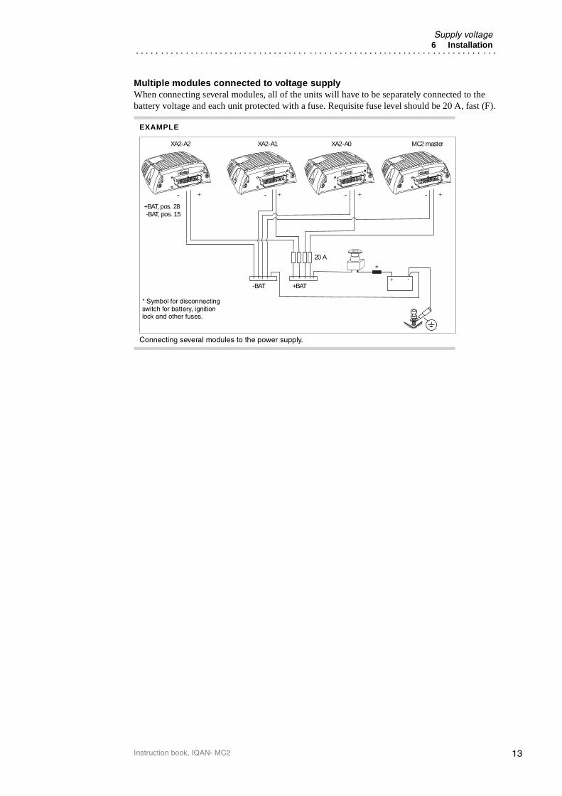
Multiple modules connected to voltage supplyWhen connecting several modules, all of the units will have to be separately connected to the battery voltage and each unit protected with a fuse. Requisite fuse level should be 20 A, fast (F).
EXAMPLE
Connecting several modules to the power supply.
+ -
XA2-A2 XA2-A1 XA2-A0 MC2 master
- + - + - + - +
+BAT, pos. 28-BAT, pos. 15
-BAT +BAT
20 A
* Symbol for disconnecting switch for battery, ignition lock and other fuses.
*
13Instruction book, IQAN- MC2

IQAN-MC2 addressing/terminating6 Installation
IQAN-MC2 addressing/terminating
Use of an ID-TagEach MC2 module can be configured by using an ID-Tag. The value of the ID-Tag will enable specific functions in the MC2 module if supported in an IQANdesign application file. This allows a single master application to be loaded into more than one MC2 and the functionality needed for the installed location is enabled by ID-tag. By default, if no ID-tag is installed the MC2 will be terminated internally to be the Bus master and will have no special configuration.
Configuration by addressConnection of an ID-Tag between address high and low will enable a numeric input to the application file in the MC2 master module. The desired functionality is built into the application file using IQANdesign software. For more information please refer to the IQANdesign user manual. For normal operation the ID-Tag is not used. It is only needed when a function has been implemented in the application file by using the address as an input.
The maximum number of addresses is eight, denoted as addresses 0, 1, 2, 3, 4, 5, 6, 7 respectively. In order to assign any MC2 module a unique address, an ID-Tag will have to be connected to the positions ADDR-H and ADDR-L.
Connecting of Id-Tag.
EXAMPLE
If having an MC2 module with an ID-Tag of address 0, the system will recognize a value of 0 to the application which will enable a user- specified functionality.
29
15
1
ADDR-H, pos.
42
28
14
ADDR-L, pos.
ID-Tag
14Instruction book, IQAN- MC2

IQAN-MC2 addressing/terminating6 Installation
TerminatingTo eliminate interference in the communications through the CAN-bus, the CAN-bus must be terminated. By default, if no ID-tag is installed the MC2 will be terminated internally to be the Bus master and will have no special configuration.
If an IQAN-MC2 is located at the end of the CAN-bus and is to be configured by address, then use an ID-tag having a combined address and terminating function. This is denoted with a "T" for terminating, after the appropriate address such as; 0T, 1T, 2T... etc. In the application, the same address value as the non-terminated ID-Tag with equivalent number will be transferred to the application.
Selecting appropriate ID-Tag• If an ID-tag is needed, check the address number used for the module.
• If the module is to be configured and is located at the end of the CAN-bus, then select the appropriate ID-Tag denoted with a "T".
NOTICE
The CAN-bus must not be terminated at the MC2 using an external regular terminating resistor, due to the fact that terminating is made from within the MC2 module by default or in conjunction with the ID-Tag.
Skip application loadingIf the ADDR_L voltage > 3.00V (ADDR_L pin shorted to ADDR_H) is detected when the unit starts (power up) the application will not be loaded. This is a special start-up mode that is used for master units and puts the MC2 in a safe state without starting any application. When this mode is desired, a jumper is put in place of an ID-Tag
15Instruction book, IQAN- MC2

USB connection6 Installation
USB connectionThe MC2 has an USB interface for communicating with the programming software, IQANdesign and for diagnostics. A flying lead cable, 5030124 may be connected to the MC2 to provide an USB type B connector interface. The connection from the module to PC can be made with a standard USB Type A male to Type B male cable.
Connection of Parker cable 5030124 is shown below.
Connecting for USB communication.
NOTICE
It is recommended that the two data wires, DATA+ and DATA-, be a twisted pair, 15 twists/meter. Use -VREF for the ground connection as shown.
USB and "ground loops" (differences in ground potential)Ground loops occur when different parts of the machine or system have different electrical grounds. When systems consisting of machines, modules, computers and other devices with different ground potentials are connected by a USB cable, a ground loop may be created. The grounds may only differ by a few millivolts, or by much more. This can be significant when compared to the low level voltage signals that are used in USB data transmission. This condition can cause problems in communicating and in extreme cases the amount of current flow can damage the USB transceiver in the PC or the module.
The best way to prevent ground loops is to ensure that your system includes isolation. Isolation protects your PC from damage and preserves the integrity of your data by physically separating the electrical connections between the PC and the unit.
Isolation can be provided by adding an isolated USB hub between the PC and the unit.
-VREF, pos 29DATA-, pos 13
DATA+, pos 12
29
15
1
42
28
14
16Instruction book, IQAN- MC2
Reference voltage, VREF6 Installation
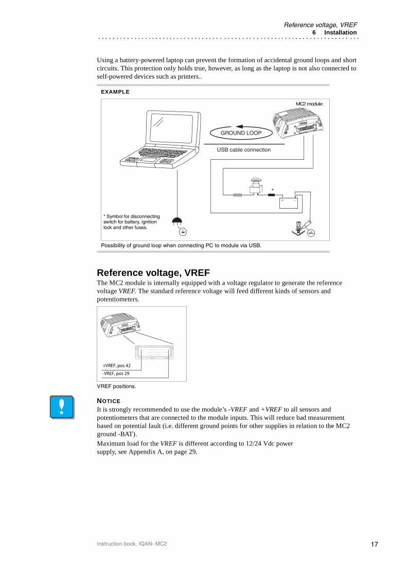
Using a battery-powered laptop can prevent the formation of accidental ground loops and short circuits. This protection only holds true, however, as long as the laptop is not also connected to self-powered devices such as printers..
Reference voltage, VREFThe MC2 module is internally equipped with a voltage regulator to generate the reference voltage VREF. The standard reference voltage will feed different kinds of sensors and potentiometers.
VREF positions.
NOTICE
It is strongly recommended to use the module’s -VREF and +VREF to all sensors and potentiometers that are connected to the module inputs. This will reduce bad measurement based on potential fault (i.e. different ground points for other supplies in relation to the MC2 ground -BAT).
Maximum load for the VREF is different according to 12/24 Vdc power supply, see Appendix A, on page 29.
EXAMPLE
Possibility of ground loop when connecting PC to module via USB.
+ -
USB cable connection
GROUND LOOP
MC2 module
* Symbol for disconnecting switch for battery, ignition lock and other fuses.
*
-VREF, pos 29
+VREF, pos 42
17Instruction book, IQAN- MC2

Voltage inputs6 Installation
Voltage inputs
Connecting sensors to the voltage inputsThe sensor signal range must be 0-5 Vdc. To detect signal errors such as short circuits or interruptions the active signal range be within 0.5-4.5 Vdc.
Active signal range.
The current consumption related to the voltage input is negligible.
The positive terminal of the sensor is connected to the +VREF position and the corresponding negative terminal to the -VREF position. The sensor signal is connected to appropriate VIN position.
NOTICE
The negative terminal of the sensor must not be connected to the chassis.Maximum load for VREF position: see Appendix A, on page 29.
EXAMPLE
Connect the positive and negative terminals of the position sensor to +VREF, position 42, and -VREF, position 29, respectively. Then connect the sensor signal to VIN-A, position 20.
Connecting VREF and sensor signal VIN-A.
0
5[V]
Active signal range
Error detection range
Error detection range
t
-VREF, pos. 29
+VREF, pos. 42
VIN-A, pos. 20
Position Sensor
42
28
14
29
15
1
18Instruction book, IQAN- MC2

Voltage inputs6 Installation
Connecting a 2-wire temperature sensor to voltage inWhen you connect a passive temperature sensor you may need to use a pull up resistor on the input signal. Please check the technical data for your specific temperature sensor.
EXAMPLE
Connect the negative terminal of the PTC (positive temperature coefficient) temperature sensor to -VREF, position 29, and the signal to VIN-A, position 20. The pull up resistor will be connected between VIN-A, position 20 and +VREF, position 42.
Connecting -VREF and temperature sensor signal VIN-A.
The pull up resistor value for a R=2000Ω PTC sensor is 4,7 KΩ.
VIN
VREF-
VREF+
Pull up
Pull up
4,7k
-VREF pos 29
VIN-A pos 20
+VREF pos 42
29
15
1
42
28
14
19Instruction book, IQAN- MC2

Voltage inputs6 Installation
Connecting switches to the voltage inputsSwitches could be connected to the voltage inputs, to create a digital on/off signal. The switches should be connected to +VREF and VIN/DIN respectively for 5V signal. The current consumption for the input is negligible.
NOTICE
Maximum load for VREF position, see Appendix A, on page 29.
It is recommended to connect system voltage +BAT to the input through a switch in order to reserve 5Vdc VREF for sensors and potentiometers.
DIN-A to DIN-EThese 5 digital inputs share pins with VIN-A to VIN-E and have high impedance characteristics. The above examples apply to these inputs.
DIN-F to DIN-MThese 8 digital inputs share pins with the RET pins of the proportional output channels E thru H. They have low impedance characteristics and an internal power clamping diode. If used they must be connected in a way that prevents "backending". See the following section for more information.
EXAMPLE
Connect the positive and negative terminals of the switch to +VREF, position 42, and VIN-A/DIN-A, position 20, respectively.
Connecting a switch to VIN-A/DIN-A and VREF.
EXAMPLE
Connect the positive and negative terminals of the switch to supply or the unit’s +BAT, position 28 and VIN-A/DIN-A, position 20, respectively.
Connecting a switch to VIN-A/DIN-A and +BAT.
VIN-A/DIN-A, pos. 20
+VREF, pos. 42
29
15
1
42
28
14
+BAT, pos. 28
29
15
1
42
28
14
VIN-A/DIN-A, pos. 20
20Instruction book, IQAN- MC2

Voltage inputs6 Installation
Connecting switches to the digital inputsWhen connecting switches to the digital inputs DIN-F thru DIN-M, extra precautions should be taken.
CAUTION
By sharing pins with the RET positions of the proportional outputs there is a possibility of ’backending’ the IQAN-MC2 unit when using those pins as digital inputs. The internal circuitry has power clamping diodes between RET pins and +BAT. This arrangement creates a risk of inadvertently supplying power to the unit by forward biasing the clamping diodes. There are two methods to avoid this:
1 The switch could be powered by the same source as the unit’s +BAT. This needs to be after any switch that would shut off power to the MC2.
2 The switch could be connected to DIN through a 1K ohm resistor to limitthe current source capability.
Remember that these flexible I/O pins must be configured in pairs of the same type, VIN, DIN or DOUT-LS.
EXAMPLE
Connect the positive and negative terminals of the switch to +BAT, position 28 and DIN-F, position 22, respectively.
Connecting a switch to DIN-F and +BAT.
EXAMPLE
Connect the positive and negative terminals of the switch to supply and DIN-F through a 1K resistor, to position 22, respectively.
Connecting a switch to DIN-F and supply thru a resistor.
+BAT, pos. 28
29
15
1
42
28
14
DIN-F, pos. 22
Supply
+ -
29
15
1
42
28
14
DIN-F, pos. 221K ohm
21Instruction book, IQAN- MC2

Frequency inputs6 Installation
Frequency inputs
Connecting sensors to the frequency inputsFrequency inputs can operate in 2 modes. Speed which is frequency and position which is a pulse count. For the frequency ranges and trigger levels, see Appendix A, on page 29.
Simple frequency sensorThe positive terminal of the frequency sensor is connected to the +VREF and the negative terminal to the -VREF respectively. The sensor signal is connected to the FIN position.
If the current consumption for the sensor exeeds the maximum load for the VREF, the sensor could be connected to the +BAT/-BAT positions.
NOTICE
The negative terminal of the sensor must not be connected to the chassis. Maximum load for VREF position, see Appendix A, on page 29.
EXAMPLE
Connect the positive and negative terminals of the frequency sensor to +VREF, position 42, and -VREF, position 29, respectively. Then connect the sensor signal to FIN-A, position 20.
Connecting of frequency sensor.
Frequency sensor
-VREF pos. 29
FIN-A pos. 20
+VREF pos. 42
29
15
1
42
28
14
22Instruction book, IQAN- MC2

Proportional outputs6 Installation
Proportional outputs The current /PWM outputs control proportional valves and devices. For the current range and loads, see Appendix A, on page 29.
FrequencyTo obtain the best performance from proportional valves the control produces a current mode (closed loop) output signal or a PWM voltage (open loop) output signal. The type of output is selectable in IQAN software. The units have an adjustable frequency which can be changed using IQAN software.
The table below shows the MC2 frequency possibilities. Any frequency may be entered in your application and is translated according to this table. The bold values are the actual frequencies in Hz output by the MC2 for proportional valve control..
Frequency (Hz) entered in appl.
Frequency (Hz) output by MC2
Frequency (Hz) entered in appl.
Frequency (Hz) output by MC2
25 25 50-52 50
26 26 53-55 53
27 27 56-58 56
28 28 59-62 59
29 29 63-66 63
30 30 67-70 67
31 31 71-76 71
32 32 77-82 77
33 33 83-90 83
34-35 34 91-99 91
36 36 100-110 100
37 37 111-124 111
38-39 38 125-142 125
40-41 40 143-166 143
42 42 167-199 167
43-44 43 200-249 200
45-47 45 250-332 250
48-49 48 333+ 333
23Instruction book, IQAN- MC2

Connecting loads to proportional outputs6 Installation
Connecting loads to proportional outputsConnecting a load, e.g. one proportional valve section, to the current mode or PWM mode outputs is done by using the COUT/CRET paired positions.
NOTICE
DO NOT install diodes across coils for Current or PWM modes!
EXAMPLE
Positive direction:Connect the proportional valve to the COUT-A, position 2 and the CRET-A+, position 16 respectively.Negative direction: Connect the proportional valve to the COUT-A, position 2 and the CRET-A- , position 30 respectively.
Connecting a load to a proportional output.
42
28
15
29
15
1
COUT-A
CRET-A-CRET-A+
Directional Valve
24Instruction book, IQAN- MC2
Digital outputs6 Installation
Digital outputs The digital outputs control relays and on/off valves. For the maximum load per output see Appendix A, on page 29.
Connecting loads to digital outputsConnecting of loads to the digital outputs such as on/off valves is done by using the DOUT-A thru DOUT-F positions and the negative battery terminal as ground.
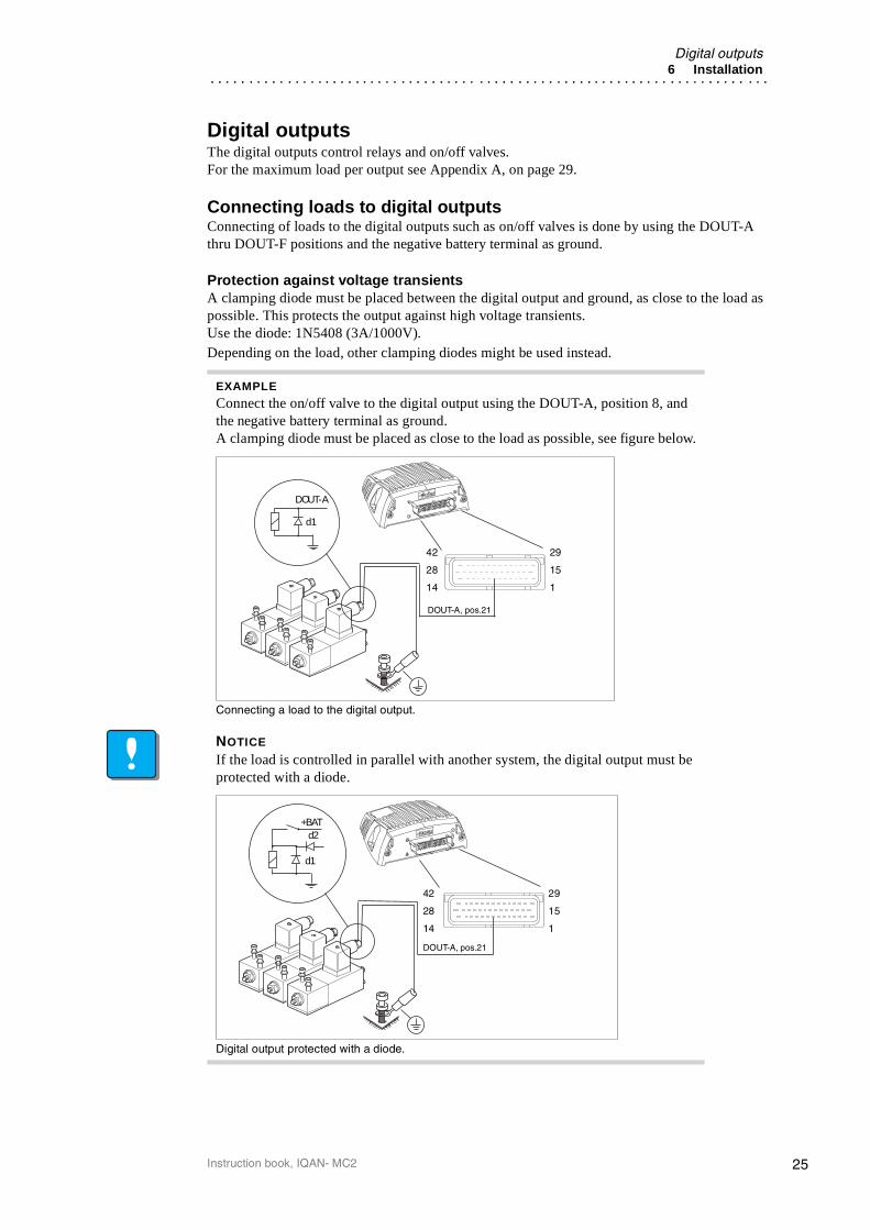
Protection against voltage transientsA clamping diode must be placed between the digital output and ground, as close to the load as possible. This protects the output against high voltage transients.Use the diode: 1N5408 (3A/1000V).Depending on the load, other clamping diodes might be used instead.
EXAMPLE
Connect the on/off valve to the digital output using the DOUT-A, position 8, and the negative battery terminal as ground.A clamping diode must be placed as close to the load as possible, see figure below.
Connecting a load to the digital output.
NOTICE
If the load is controlled in parallel with another system, the digital output must be protected with a diode.
Digital output protected with a diode.
29
15
1
d1
DOUT-A
DOUT-A, pos.21
42
28
14
DOUT-A, pos.21
+BATd2
d1
29
15
1
42
28
14
25Instruction book, IQAN- MC2

Low-side digital outputs6 Installation
Low-side digital outputs The low-side digital outputs may control relays and on/off valves. For the maximum load per output see Appendix A, on page 29.
Connecting loads to low-side digital outputsConnecting of loads to the low-side digital outputs such as on/off valves is done by using the DOUT(LS)-I thru DOUT(LS)-X positions and one or more DOUT channels as supply.
Protection against voltage transientsA clamping diode must be placed between the source and low-side digital output, as close to the load as possible. This protects the output against high voltage transients.Use the diode: 1N5408 (3A/1000V).Depending on the load, other clamping diodes might be used instead.
CAUTION
Loads on DOUT with Low-Side switch (DOUT[LS]-I to DOUT[LS]-X) must be controlled on the high-side by connection to a DOUT with High-Side switch (DOUT-A to DOUT-H) for safe function. The total sum of current supplied to the loads controlled by a number of DOUT[LS] is limited to 2000mA.
Remember that these flexible I/O pins must be configured in pairs of the same type, VIN, DIN or DOUT-LS.
EXAMPLE
Connect the on/off valves to the low-side digital outputs using the DOUT(LS)-I, position 16, DOUT(LS)-J, position 30 and the DOUT-A, position 2 as supply.A clamping diode must be placed as close to the load as possible, see figure below.
Connecting loads to the low-side digital outputs.
29
15
1
d1
DOUT-A
DOUT-A, pos.21
42
28
14
DOUT(LS)-I
DOUT(LS)-I, pos.16
DOUT(LS)-J, pos.30
26Instruction book, IQAN- MC2

Start-up procedures7 Start-up
7 Start-up
Start-up proceduresThis chapter contains instructions for action to be taken in connection with the initial start, for example, setting values, calibrating and testing the system.
WARNING
Risk of injury!If the control system is not fitted properly, the machine could move uncontrollably. The machine’s engine shall not be started before the control system is completely fitted and its signals are verified.
Starting the control system
Start the control system as follows:• Prior to start, all modules and cables are to be fitted correctly.
• Check fuses, i.e. make sure that the supply voltage to the modules is equipped with the cor-rect fuse.
• Make sure that connections for supply voltage and return lines are correct in the cable’s con-ductor joint.
• Make sure that the ID-tag is connected properly if used.
• Make sure the emergency stop works.
The emergency stop should disconnect the supply voltage to all modules.
Emergency stop.
Alternatively, the emergency stop may also shut off the diesel engine or a dump valve, and with that depressurize the hydraulic system.
+BATDump valve
27Instruction book, IQAN- MC2

Start-up procedures7 Start-up
Prepare for system start
WARNING
Make sure no one is in dangerous proximity to the vehicle to avoidinjuries when it starts.
Prepare for the initial system start as follows:• The engine for the hydraulic system’s pump shall be in off position.
• Make sure that all connectors are properly connected.
• Turn on the control system.
• Make sure that voltage is being supplied to all modules, the green diode shall be illuminated on all modules. Also make sure that master is in contact with all modules by checking the master’s status LED. Error codes are blinked if the master is not in contact with one or more of the modules.
• Make sure the emergency stop is functioning properly.
Start the system
Start the system as follows:• Start the engine for the hydraulic system’s pump, assuming that the above mentioned inspec-
tions have been carried out and shown correct values.
• Calibrate and adjust input and output signals according to the instructions related to the mas-ter menu system and check each and every output function carefully.
• In addition to these measures, the machine shall also meet the machine directives for the country in question.
28Instruction book, IQAN- MC2

IQAN-MC2 Technical OverviewAppendix A
Appendix A
IQAN-MC2 Technical Overview
Absolute Maximum Ratingsa
a.The “Absolute Maximum Ratings” table lists the maximum limits to which the device can be subjected without damage. This doesn´timply that the device will function at these extreme conditions, only that, when these conditions are removed and the device operated with-in the “Recommended Operating Conditions”, it will still be functional and its useful life wonít have been shortened.
ParameterLimit values
Unit Remarkmin. typ. max.
Ambient temperature, TA
Storage temperature
– 40– 40
+85+100
°C
Voltage supply on +BAT 6 34 V Reverse polarity pro-tected with 20A fuse.
Voltage on any pin withrespect to -BAT
34 V Max voltage on USBsignals D+ / D- is 3.5V
Maximum current into -VREF 2 A
Maximum current sourced or sinked by all outputs
20 A
Environmental ratings
ParameterLimit values
Unit Remarkmin. typ. max.
EMIISO 14982:1998EN 55025:2003ISO 11452-2:1995ISO 11452-4:2001ISO 7637-3:1995ISO 7637-2:1990
10015080
MHzMHzV/mmAVV
30-3000 MHz0.15-108 MHz20-1000 MHz1-200 MHz
1a,2,3a,3b,4,5
ESDISO 10605:2001 15
88
kV aircontacthandling
Mechanical environmentIEC 68-2-64:1993 FhIEC 68-2-29:1987 Eb
0.440
g2/Hzg
15- 250 Hz, 10 hours6 ms
Climate environmentIEC 600529:2001 IP66DIN 40050 Part 9:1993 IP6K9KIEC 60068-2-30:1985 DbIEC 60068-2-78:2001IEC 60068-2-2:1993-01 BbIEC 60068-2-1:1993-02 AbIEC 60068-2-14:1984 Nb
330621721610 x 6
minseccyclesdayshourhourhour
30 kPa, 12.5 l/min1000kPa, +80°C+55°C, 95% RH44°C, 93% RH70°C-40°C-40°C to 70°C
Chemical environmentIEC 68-2-52:1996 Kb 3 days
29Instruction book, IQAN-MC2

IQAN-MC2 Technical OverviewAppendix A
Recommended Operating Conditionsa
ParameterLimit values
Unit Remarkmin. typ. max.
Ambient temperature, TA – 30 +70 °C
Voltage supply, VBAT 11 32 V
Total load on COUT/PWMOUT/DOUT 16 A
a.Recommended operating conditions are given for maximum and minimum conditions where normal performance is still available fromthe device. Once the normal operating conditions are exceeded, the performance of the device may suffer.
SystemTA = +25 °C (unless otherwise specified)
ParameterLimit values
Unit Remarkmin. typ. max.
Start-up delay 250 ms Power to activated output
Dither frequency, DF 25 333 Hz
System cycle time 5 100 ms
Sample rate local I/O 5 100 ms System cycle time
Output voltage on VREF 4.95 5.00 5.05 V load < 50mA
Maximum load current on VREFVBAT =11V to 32V
150 mA
Current supplyVBAT =14VVBAT =28V
200160
mA outputs = offno load on VREF
Current supply RTC+RTC =14V+RTC =28V
48
mA Same supply current for VBAT=0V or VBAT > 11V
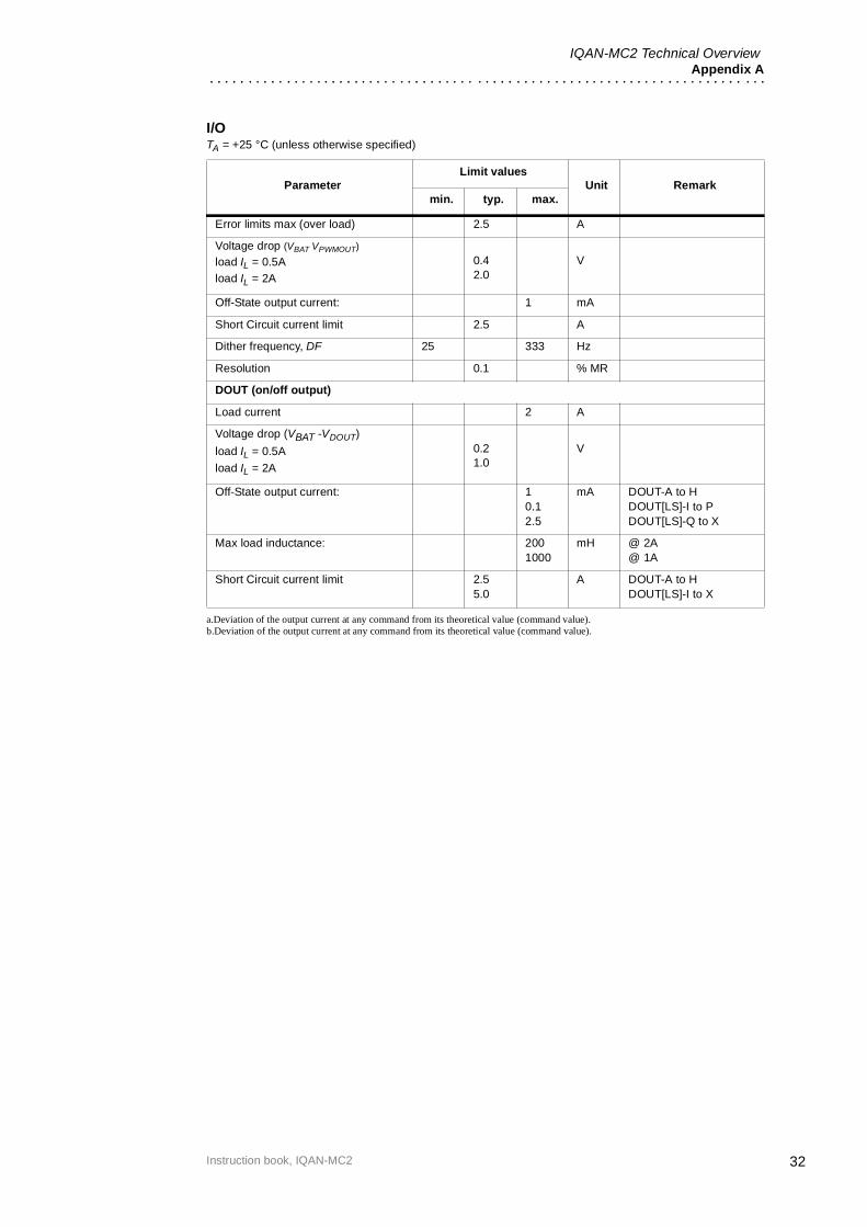
I/OTA = +25 °C (unless otherwise specified)
ParameterLimit values
Unit Remarkmin. typ. max.
VIN (Voltage input)
Signal range low 0 0.05 V
Signal range high 4.95 5.00 V
Input resistance 36 kΩ
Signal resolution 1.2 mV 5000/4095 = 1.2
Relative accuracya 10 mV
DIN (On/off input)
Input signal low 1.0 V
Input signal high 4.0 V
Input hysteresis 1.0 V
Input resistance 36 kΩ
FIN (Frequency input)
Input signal low 1.0 V
Input signal high 4.0 V
Input hysteresis 0.3 V
30Instruction book, IQAN-MC2

IQAN-MC2 Technical OverviewAppendix A
Input resistance 36 kΩ
Input frequency low 21/Tsc
0
Hz Speed mode - normalSpeed mode - fastPosition mode
Input frequency high 20.000 Hz
Step response time(Speed mode)
Tsc
Step response time(Position mode)
Tsc
Zero detection time(Speed mode, start or stop <20 Hz)
1.1Tsc
s Speed mode - normalSpeed mode - fast
COUT (closed-loop mode)
Signal range (IL) 100 2000 mA
Load 3.5 Ω
Error limit min.(open load) 50 us
Error limit max. (overload) T-500 us T = 1/fdither
Voltage drop (VBAT -VDOUT)
IL = 500mAIL = 2000mA
0.42.0
V
Off-State output current: 1 mA
Short Circuit current limit 2.5 A
Relative accuracyb 15 mA PVC25-12VPVC25-24VDF161-12VDF161-24Vpump/motor
Temperature error 15 mA TA= -40°C to 70°C
(nominal @ 25°C)IL = 500mA
Power supply rejectionVBAT= 11... 18V
VBAT= 24... 32V
22
mA PVC25-12/24VDF161-12/24V
Load regulationVBAT=14V, RL=4... 9 ΩVBAT=28V, RL=22... 34 Ω
22
mA Load=PVC25-12V, DF161-12VPVC25-24V, DF161-24V
Dither frequency, DF 25 333 Hz
Resolution 0.11.0
mAus
Dependent on load, power supply and dither frequency.
PWMOUT (open-loop mode)
Signal range 0 95 % MR
Load current 2 A
Pulse width low T/1000 s T = 1/fdither
Pulse width high T s
Error limits min (open load) - mA No open load detection
I/OTA = +25 °C (unless otherwise specified)
ParameterLimit values
Unit Remarkmin. typ. max.
31Instruction book, IQAN-MC2
IQAN-MC2 Technical OverviewAppendix A
Error limits max (over load) 2.5 A
Voltage drop (VBAT VPWMOUT)
load IL = 0.5Aload IL = 2A
0.42.0
V
Off-State output current: 1 mA
Short Circuit current limit 2.5 A
Dither frequency, DF 25 333 Hz
Resolution 0.1 % MR
DOUT (on/off output)
Load current 2 A
Voltage drop (VBAT -VDOUT)
load IL = 0.5A
load IL = 2A
0.21.0
V
Off-State output current: 10.12.5
mA DOUT-A to HDOUT[LS]-I to PDOUT[LS]-Q to X
Max load inductance: 2001000
mH @ 2A@ 1A
Short Circuit current limit 2.55.0
A DOUT-A to HDOUT[LS]-I to X
a.Deviation of the output current at any command from its theoretical value (command value).b.Deviation of the output current at any command from its theoretical value (command value).
I/OTA = +25 °C (unless otherwise specified)
ParameterLimit values
Unit Remarkmin. typ. max.
32Instruction book, IQAN-MC2
33
Error codes, messages and actionsAppendix B
Instruction book, IQAN-MC2
Appendix B
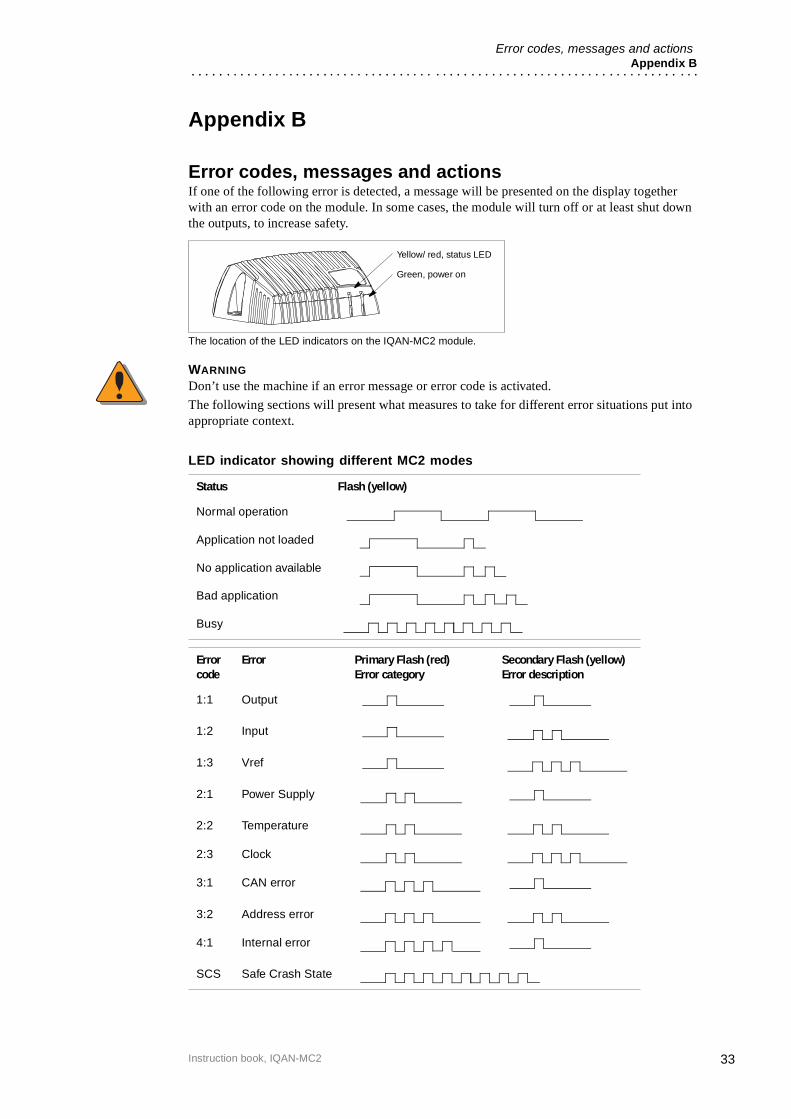
Error codes, messages and actionsIf one of the following error is detected, a message will be presented on the display together with an error code on the module. In some cases, the module will turn off or at least shut down the outputs, to increase safety.
The location of the LED indicators on the IQAN-MC2 module.
WARNING
Don’t use the machine if an error message or error code is activated.
The following sections will present what measures to take for different error situations put into appropriate context.
LED indicator showing different MC2 modes
Status Flash (yellow)
Normal operation
Application not loaded
No application available
Bad application
Busy
Error code
Error Primary Flash (red)Error category
Secondary Flash (yellow)Error description
1:1 Output
1:2 Input
1:3 Vref
2:1 Power Supply
2:2 Temperature
2:3 Clock
3:1 CAN error
3:2 Address error
4:1 Internal error
SCS Safe Crash State
Green, power on
Yellow/ red, status LED
34
Dimensioning of the IQAN-MC2 moduleAppendix C
Instruction book, IQAN-MC2
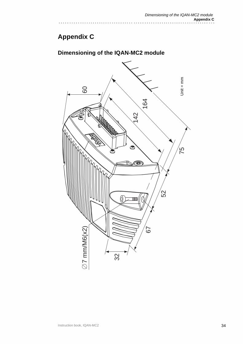
Appendix C
Dimensioning of the IQAN-MC2 module
7 m
m/M
6(x2
)
142
164
60
32
67
52
75U
nit =
mm

Parker HannifinMobile Controls DivisionSE-435 35 MölnlyckeSwedenTel +46 31 750 44 00Fax +46 31 750 44 21www.parker.com
Parker HannifinMobile Controls Division203 Pine StreetForest City, NC 28043USATel +1 828 245 3233Fax +1 828 248 9733
Publ. no HY17-8388-IB/UKEdition 10/2008
For the latest information visit our website www.iqan.com Information in this instructionbook is subject to change without notice