InstruCalc8 QuickStart Guide (1)
26
1 INSTRUCALC VERSION 8 QUICKSTA RT GUIDE March 2013 1.0 START MENU InstruCalc8 allows a range quite involved calculation s based on the applicable codes and standards. It requires that data be entered in a precise and orderly manner. The learning curve can be quite steep, but once familiarity is achieved, then the software is particularly useful providing calculations independent of suppliers' and manufacturers' own software. This QuickStart Guide covers only a fraction of the software's capabilities; a hardcopy manual of more than 300 pages is supplied with the software plus a comprehensive Help file. On opening InstruCalc Version 8 you will be presented with the following Main Menu giving you access to the four modules of the program: Clicking [More] displays the various sub-modules. Selecting the individual modules by clicking the header button shows the following start-up panes for each.
-
Upload
bari-ipung-guntur -
Category
Documents
-
view
241 -
download
0
Transcript of InstruCalc8 QuickStart Guide (1)

8/10/2019 InstruCalc8 QuickStart Guide (1)
http://slidepdf.com/reader/full/instrucalc8-quickstart-guide-1 1/26
1
INSTRUCALC VERSION 8QUICKSTART GUIDE
March 2013
1.0 START MENU
InstruCalc8 allows a range quite involved calculations based on the applicable codes and standards. It requires that data be entered in a preciseand orderly manner. The learning curve can be quite steep, but once familiarity is achieved, then the software is particularly useful providingcalculations independent of suppliers' and manufacturers' own software. This QuickStart Guide covers only a fraction of the software's capabilities;a hardcopy manual of more than 300 pages is supplied with the software plus a comprehensive Help file.
On opening InstruCalc Version 8 you will be presented with the following Main Menu giving you access to the four modules of the program:
Clicking [More] displays the various sub-modules.
Selecting the individual modules by clicking the header button shows the following start-up panes for each.

8/10/2019 InstruCalc8 QuickStart Guide (1)
http://slidepdf.com/reader/full/instrucalc8-quickstart-guide-1 2/26
2
CONTROL VALVE SIZING PROGRAMS FLOW ELEMENT SIZING PROGRAMS
Each module has a New Calculation option at the top of eachpane.
A selection here may take you immediately to a data entrydialog (eg Control Valves) or to another menu from where youselect the desired routine (eg Flow Element Sizing).
After this selection routine you will be in the appropriate dataentry dialog where first you must make your selection of unitsand other options.
For instance try:
Control Valve Sizing
Liquid
[New calc]
To return to the module menu use: File | Program menu
To return to the Main Menu use: File | Exit
Now try:
Flow Elements
[Gas flow]
ISO Orifice Plates
Concentric – Flange Taps [OK]
RELIEF VALVE SIZING PROGRAMS PROCESS DATA CALCULATIONS

8/10/2019 InstruCalc8 QuickStart Guide (1)
http://slidepdf.com/reader/full/instrucalc8-quickstart-guide-1 3/26
3
2.0 UNITS AND CALCULATION OPTIONS SELECTION
Once any of the four modules is activated, you need to preset your units and other data using the [Change setup] button which appears bottom right on all modules- as shown by the red arrow in the image below. It is recommended not to use the buttons on the calculation screen itself (see below) to set your initial units of choice. These buttons are for fine tuning each line after initial units selection is made on the [Change setup] screen.
The ‘Calculation Options’ dialogincludes:
Operating pressures, liquid densityoptions, available calculations, liquidor gas unit options, local or baseconditions, pressure tap location,drain hole, etc.
Options vary depending on thecalculation screen you are workingfrom.
Note: you can save your unitsselection as your default, but you will still have to access this dialog to set other conditions for the individual calculations.
Once you have selected your desired units for calculation on this screen, you may fine tune the individual input units on the calculation screen using the line item
buttons as shown below.

8/10/2019 InstruCalc8 QuickStart Guide (1)
http://slidepdf.com/reader/full/instrucalc8-quickstart-guide-1 4/26
4
Use these buttons on the Calculation screen for fine tuning after you have made your base unit selection from the Change setup options screen.
8/10/2019 InstruCalc8 QuickStart Guide (1)
http://slidepdf.com/reader/full/instrucalc8-quickstart-guide-1 5/26
5
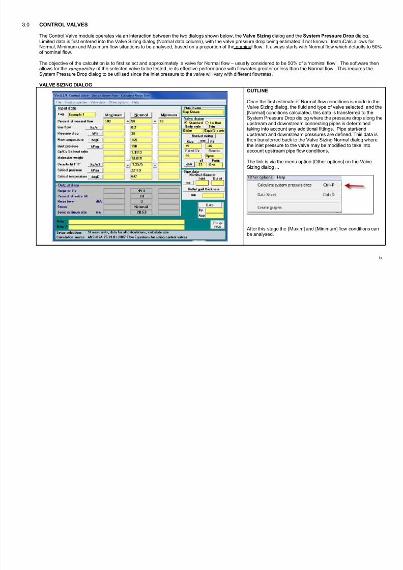
3.0 CONTROL VALVES
The Control Valve module operates via an interaction between the two dialogs shown below, the Valve Sizing dialog and the System Pressure Drop dialog.Limited data is first entered into the Valve Sizing dialog (Normal data column), with the valve pressure drop being estimated if not known. InstruCalc allows for Normal, Minimum and Maximum flow situations to be analysed, based on a proportion of the nominal flow. It always starts with Normal flow which defaults to 50%of nominal flow.
The objective of the calculation is to first select and approximately a valve for Normal flow – usually considered to be 50% of a ‘nominal flow’. The software then
allows for the rangeabil i ty of the selected valve to be tested, ie its effective performance with flowrates greater or less than the Normal flow. This requires theSystem Pressure Drop dialog to be utilised since the inlet pressure to the valve will vary with different flowrates.
VALVE SIZING DIALOG
OUTLINE
Once the first estimate of Normal flow conditions is made in theValve Sizing dialog, the fluid and type of valve selected, and the[Normal] conditions calculated, this data is transferred to theSystem Pressure Drop dialog where the pressure drop along theupstream and downstream connecting pipes is determinedtaking into account any additional fittings. Pipe start/endupstream and downstream pressures are defined. This data is
then transferred back to the Valve Sizing Normal dialog wherethe inlet pressure to the valve may be modified to take intoaccount upstream pipe flow conditions.
The link is via the menu option [Other options] on the ValveSizing dialog ...
After this stage the [Maxim] and [Minimum] flow conditions canbe analysed.

8/10/2019 InstruCalc8 QuickStart Guide (1)
http://slidepdf.com/reader/full/instrucalc8-quickstart-guide-1 6/26
6
SYSTEM PRESSURE DROP DIALOG
Data entered into this dialog determines upstream anddownstream pipe conditions and may amend the valve inletpressure accordingly. Calculation is via the [Normal] button atthe top of the data column.
Calculated data is returned to the Valve Sizing dialog via the
buttons shown below.
and returns to the Valve Sizing dialog where the[Normal] calculation needs to be repeated.
Here the valve inlet pressure will be amended dependent on thedefined connecting pipe flow conditions.

8/10/2019 InstruCalc8 QuickStart Guide (1)
http://slidepdf.com/reader/full/instrucalc8-quickstart-guide-1 7/26
7
Once the Normal conditions have been re-calculated, the scroll barsbecome active. Move them up or down to calculate variouspercentages of Normal.
The System Pressure Drop dialog is now automatically linked, so thatvariations in flowrate and system properties for both the valve and theadjoining pipework are simultaneously calculated – providing a guide
the rangeability of the selected valve.
N o t e – a lw a y s m o v e t h e M i n i m u m s c r o l l b a r f i r s t , t h e M a x i m u m
s c r o l l b a r s e c o n d .
SUMMARY
The objective of the calculation is to first size or select a valve for Normal flow – usually considered to be 50% of a ‘nominal flow’. The software then allows for therangeability of the selected valve to be tested, ie its effective performance with flowrates greater or less than the Normal flow. This requires system pressure dropdialog to be utilised since the inlet pressure to the valve will vary with different flowrates.

8/10/2019 InstruCalc8 QuickStart Guide (1)
http://slidepdf.com/reader/full/instrucalc8-quickstart-guide-1 8/26
8
3.1 CONTROL VALVE: EXAMPLE 1, STEAM FLOWSTEP-BY-STEP EXAMPLE
The steps described below must be followed precisely.
STEP ACTION IMAGE COMMENT
CONTROL VALVE SIZING – STAGE 1
1 Select Control Valves from theMain Menu and then select:
Gas, steam or vapor
[New calc]
2 Select units.
[OK]
Mass SI units will be used throughout thisQuickStart Guide.
3 Enter a Tag

8/10/2019 InstruCalc8 QuickStart Guide (1)
http://slidepdf.com/reader/full/instrucalc8-quickstart-guide-1 9/26
9
4 Input in the Normal datacolumn –
Gas flow rate
Pressure drop (best guess)
Flow temperature
Inlet pressure (best guess)
Pressures may be precisely known at this stageor may be refined later via the System PressureDrop dialog.
5 Define your Normal flow fluid
Select superheated steamand appropriate properties willbe displayed.

8/10/2019 InstruCalc8 QuickStart Guide (1)
http://slidepdf.com/reader/full/instrucalc8-quickstart-guide-1 10/26
10
6 Enter Valve Data This may be from the valve database as shown -Standard or Lo Flow - or directly entered.
Note: If selecting a valve from the database, youdo not specify Size, Rated Cv or Fd as thesoftware will determine this. Usually the valveselection will be one size less than the specified
pipe nominal size.
7 Enter pipe data or leave blank. Leave blank
8 Calculate using the [Normal]button at the top of the datacolumn.
Initial output data is calculated.
D o n o t u s e s c r o l l b a r s a t t h i s p o i n t .

8/10/2019 InstruCalc8 QuickStart Guide (1)
http://slidepdf.com/reader/full/instrucalc8-quickstart-guide-1 11/26
11
CONTROL VALVE SIZING – STAGE 2: SYSTEM PRESSURE DROP
Note this dialog must be completed beforeattempting to test the rangeability of the selectivevalve via the
and buttons.
9 Access the System PressureDrop dialog.
10 Enter the piping configurationdata in the left hand sidepanes.
This sets up the pipe system in which the valvesits and allows for the accurate calculation of inletpressure to the valve for the three calculations. –Normal, Minimum and Maximum.
Access accurate pipe size data from the
underlying database. Or pipe size can be entereddirectly.

8/10/2019 InstruCalc8 QuickStart Guide (1)
http://slidepdf.com/reader/full/instrucalc8-quickstart-guide-1 12/26
12
11 Enter the Source andDestination pressures for Normal flow only.
The Normal flow value is carried over from theValve Sizing dialog.
12 Enter any additional Inlet andOutlet equipment losses
None
13 Calculate the system for normalflow.
Use the button at the top of the data column.
Precise Normal output data is now calculated for transfer back to the Control Valve dialog
14 Transfer the Normal flow databack to the Valve Sizing dialog.
This will update the inlet pressure to the valve.

8/10/2019 InstruCalc8 QuickStart Guide (1)
http://slidepdf.com/reader/full/instrucalc8-quickstart-guide-1 13/26
13
15 Re-calculate the Normal values.

8/10/2019 InstruCalc8 QuickStart Guide (1)
http://slidepdf.com/reader/full/instrucalc8-quickstart-guide-1 14/26
14
16 Now activate the scroll bars usingthe Minimum data column first.
Always activate the Minimum scroll bar first.Scroll up on the Maximum data column to find themaximum flowrate the selected valve can take
Scroll the Minimum data column for the minimumallowable flow.
17 Test the rangeability of the valveby increasing the Maximum flowto a maximum.
At 72% of the nominal flow, the selected valve is toosmall.
[Cancel]

8/10/2019 InstruCalc8 QuickStart Guide (1)
http://slidepdf.com/reader/full/instrucalc8-quickstart-guide-1 15/26
15
18 Add some identifying data in theNotes rows and the date and plotthe valve charts.
Select different charts for themenu options at the top.
Cv Pressure Drop Linear Trim EqualPercent
Save your design.

8/10/2019 InstruCalc8 QuickStart Guide (1)
http://slidepdf.com/reader/full/instrucalc8-quickstart-guide-1 16/26
16
3.2 CONTROL VALVE: EXAMPLE 2, WATER FLOW
1 VALVE SIZING DIALOG
Select Liquid flow and [New calc]
Input in the Normal data column -
Liquid flow rate
Pressure drop (best guess)
Flow temperature
Inlet pressure (best guess)
Select water and a butterfly valve
Calculate [Normal] flow to get theimage shown opposite.

8/10/2019 InstruCalc8 QuickStart Guide (1)
http://slidepdf.com/reader/full/instrucalc8-quickstart-guide-1 17/26
17
2 SYSTEM PRESSURE DROPDIALOG
Enter upstream and downstreampipe data.
Transfer back to the Valve Sizingdialog.
3 Re-calculate Normal, maximum andMinimum conditions.
Note that InstruCalc has selected an appropriatevalve size for the conditions shown, viz 75mm.

8/10/2019 InstruCalc8 QuickStart Guide (1)
http://slidepdf.com/reader/full/instrucalc8-quickstart-guide-1 18/26
18
4 Increase the Maximum flow to 70%of nominal.
InstruCalc shows that the valve is too small.
Select the choice to use a larger valve…
[Yes]
Note the valve size has increased to 100mm.
5 Plot charts.
Save your work

8/10/2019 InstruCalc8 QuickStart Guide (1)
http://slidepdf.com/reader/full/instrucalc8-quickstart-guide-1 19/26
19
4.0 ORIFICE PLATE CALCULATION - LIQUID FLOW
1 Select the OrificeCalculation shownopposite.
2 [Change setup] Note the options here, particularly thechoice of three calculations available:
Calculate differential range
Calculate flowrate
Calculate orifice size

8/10/2019 InstruCalc8 QuickStart Guide (1)
http://slidepdf.com/reader/full/instrucalc8-quickstart-guide-1 20/26
20
3 Enter the data asshown then selectwater.
Note: the ‘fluid’ field is simply a textentry
4 Specify the pipe
material, ID andelement material andcalculate
5 Explore Options Save your work

8/10/2019 InstruCalc8 QuickStart Guide (1)
http://slidepdf.com/reader/full/instrucalc8-quickstart-guide-1 21/26
21
5.0 RELIEF VALVES
The Relief Valve module offers a variety of relief valve type calculations for determining the appropriate area of flow, viz:
The Relief Valve module operates via an interaction between the two dialogs shown below, the Area Sizing dialog on the left and the Pipe Loss dialog on the right.
The link is via the menu
option [Pipe losses] onthe Area Sizing dialog…
…and the Transfer button on the Pipe Lossdialog.

8/10/2019 InstruCalc8 QuickStart Guide (1)
http://slidepdf.com/reader/full/instrucalc8-quickstart-guide-1 22/26
22
The step-by-step process described below must be followed precisely and specifically applies to a Steam Relief – Known flow.
STEP ACTION IMAGE COMMENT
AREA SIZING
1
2 Select units
3 Input
Tag Fluid Name (Steam)
Text entry.

8/10/2019 InstruCalc8 QuickStart Guide (1)
http://slidepdf.com/reader/full/instrucalc8-quickstart-guide-1 23/26
23
4 Select ASME Section 8, BalancedBellows and no Rupture disk
5 Enter initial data. Note Percent Overpressure and Valve dischargecoefficient have default values. These can be over-written.
6 Calculate to display valve area.
7 ...and Output Data Note: InstruCalc calculates the Valve Capacity – it’s onthis value that the valve is sized.

8/10/2019 InstruCalc8 QuickStart Guide (1)
http://slidepdf.com/reader/full/instrucalc8-quickstart-guide-1 24/26
24
PIPE LOSS
8 Access the Pipe losses dialog.
9 Enter the piping configuration
data.
Calculate.
and calculate and transfer back tothe
Note: The Valve capacity is carried over
and used for the pipe loss calculations.
10 Transfer data back to the AreaSizing dialog.

8/10/2019 InstruCalc8 QuickStart Guide (1)
http://slidepdf.com/reader/full/instrucalc8-quickstart-guide-1 25/26
25
11 Re-calculate.
REGISTERING AND PURCHASING INSTRUCALC 8
If you have been supplied with a demo version of InstruCalc, it should run for 14+ days in fully-functional format. We can extend that period on request. In order toregister InstruCalc 8 for an extension of the trial or for a permanent licence, you need to follow these instructions
1
2

8/10/2019 InstruCalc8 QuickStart Guide (1)
http://slidepdf.com/reader/full/instrucalc8-quickstart-guide-1 26/26
26
DO NOT CONTACT GULF
CONTACT ACCUTECH ON
Send Accutech both codes and/or copy this image
IMPORTANT NOTE
You must leave this image displayed ie DO NOT EXIT THE SOFTWARE OR TURN OFF YOUR COMPUTER – otherwise the code numbers willchange and the Registration Key we issue will not work.
Enter the Registration Key and [OK]
Only Registration Key 1 is required.