Installer's Guide Programmable Zone Sensor for … Training/Trane RTU info/T-stats/Zone... ·...
16
Installers Guide Programmable Zone Sensor for Constant Volume (CV) Units and Heat Pump (HP) Units October 2004 ACC-SVN28A-EN 18-HD60D29-5 Models: Used With: BAYSENS019C 3 - 25 Ton Packaged Heat/Cool Units ASYSTAT666C 3 - 20 Ton Packaged Heat Pump Units 27.5 - 50 Ton Packaged Rooftop Units 20 - 130 Ton Packaged Rooftop Units 20 - 80 Ton Commercial Self Contained Units
Transcript of Installer's Guide Programmable Zone Sensor for … Training/Trane RTU info/T-stats/Zone... ·...

Installers Guide
Programmable Zone Sensor for Constant Volume (CV) Unitsand Heat Pump (HP) Units
October 2004
ACC-SVN28A-EN18-HD60D29-5
Models: Used With:BAYSENS019C 3 - 25 Ton Packaged Heat/Cool UnitsASYSTAT666C 3 - 20 Ton Packaged Heat Pump Units
27.5 - 50 Ton Packaged Rooftop Units20 - 130 Ton Packaged Rooftop Units20 - 80 Ton Commercial Self Contained Units
2 ACC-SVN28A-EN
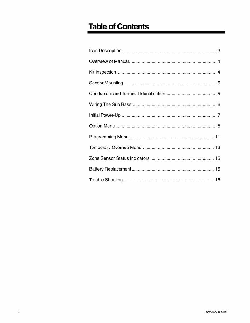
Table of Contents
Icon Description ........................................................................... 3
Overview of Manual...................................................................... 4
Kit Inspection ................................................................................ 4
Sensor Mounting .......................................................................... 5
Conductors and Terminal Identification ........................................ 5
Wiring The Sub Base ................................................................... 6
Initial Power-Up ............................................................................ 7
Option Menu ................................................................................. 8
Programming Menu .................................................................... 11
Temporary Override Menu ......................................................... 13
Zone Sensor Status Indicators ................................................... 15
Battery Replacement .................................................................. 15
Trouble Shooting ........................................................................ 15
3ACC-SVN28AEN
General Information
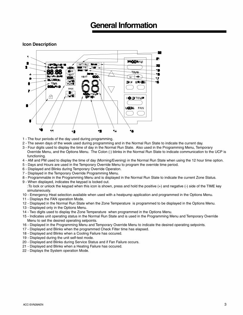
Icon Description
1 - The four periods of the day used during programming.2 - The seven days of the week used during programming and in the Normal Run State to indicate the current day.3 - Four digits used to display the time of day in the Normal Run State. Also used in the Programming Menu, Temporary
Override Menu, and the Options Menu. The Colon (:) blinks in the Normal Run State to indicate communication to the UCP isfunctioning.
4 - AM and PM used to display the time of day (Morning/Evening) in the Normal Run State when using the 12 hour time option.5 - Days and Hours are used in the Temporary Override Menu to program the override time period.6 - Displayed and Blinks during Temporary Override Operaton.7 - Displayed in the Temporary Override Programming Menu.8 - Programmable in the Programming Menu and is displayed in the Normal Run State to indicate the current Zone Status.9 - When displayed, indicates the keypad is locked out.
:To lock or unlock the keypad when this icon is shown, press and hold the positive (+) and negative (-) side of the TIME keysimutaneously.
10 - Emergency Heat selection available when used with a heatpump application and programmed in the Options Menu.11 - Displays the FAN operation Mode.12 - Displayed in the Normal Run State when the Zone Temperature is programmed to be displayed in the Options Menu.13 - Displayed only in the Options Menu.14 - Two digits used to display the Zone Temperature when programmed in the Options Menu.15 - Indicates unit operating status in the Normal Run State and is used in the Programming Menu and Temporary Override
Menu to set the desired operating setpoints.16 - Displayed in the Programming Menu and Temporary Override Menu to indicate the desired operating setpoints.17 - Displayed and Blinks when the programmed Check Filter time has elapsed.18 - Displayed and Blinks when a Cooling Failure has occured.19 - Displayed during the unit self-test mode.20 - Displayed and Blinks during Service Status and if Fan Failure occurs.21 - Displayed and Blinks when a Heating Failure has occured.22 - Displays the System operation Mode.
4 ACC-SVN28A-EN
General Information
Overview of Manual
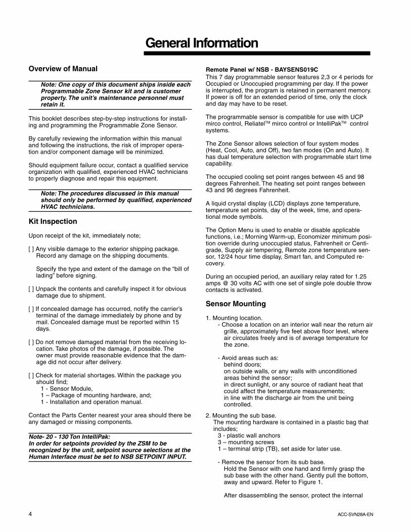
Note: One copy of this document ships inside eachProgrammable Zone Sensor kit and is customerproperty. The unit’s maintenance personnel mustretain it.
This booklet describes step-by-step instructions for install-ing and programming the Programmable Zone Sensor.
By carefully reviewing the information within this manualand following the instructions, the risk of improper opera-tion and/or component damage will be minimized.
Should equipment failure occur, contact a qualified serviceorganization with qualified, experienced HVAC techniciansto properly diagnose and repair this equipment.
Note: The procedures discussed in this manualshould only be performed by qualified, experiencedHVAC technicians.
Kit Inspection
Upon receipt of the kit, immediately note;
[ ] Any visible damage to the exterior shipping package.Record any damage on the shipping documents.
Specify the type and extent of the damage on the “bill oflading” before signing.
[ ] Unpack the contents and carefully inspect it for obviousdamage due to shipment.
[ ] If concealed damage has occurred, notify the carrier’sterminal of the damage immediately by phone and bymail. Concealed damage must be reported within 15days.
[ ] Do not remove damaged material from the receiving lo-cation. Take photos of the damage, if possible. Theowner must provide reasonable evidence that the dam-age did not occur after delivery.
[ ] Check for material shortages. Within the package youshould find;
1 - Sensor Module,1 – Package of mounting hardware, and;1 - Installation and operation manual.
Contact the Parts Center nearest your area should there beany damaged or missing components.
Note- 20 - 130 Ton IntelliPak:In order for setpoints provided by the ZSM to berecognized by the unit, setpoint source selections at theHuman Interface must be set to NSB SETPOINT INPUT.
Remote Panel w/ NSB - BAYSENS019CThis 7 day programmable sensor features 2,3 or 4 periods forOccupied or Unoccupied programming per day. If the poweris interrupted, the program is retained in permanent memory.If power is off for an extended period of time, only the clockand day may have to be reset.
The programmable sensor is compatible for use with UCPmirco control, ReliatelTM mirco control or IntelliPakTM controlsystems.
The Zone Sensor allows selection of four system modes(Heat, Cool, Auto, and Off), two fan modes (On and Auto). Ithas dual temperature selection with programmable start timecapability.
The occupied cooling set point ranges between 45 and 98degrees Fahrenheit. The heating set point ranges between43 and 96 degrees Fahrenheit.
A liquid crystal display (LCD) displays zone temperature,temperature set points, day of the week, time, and opera-tional mode symbols.
The Option Menu is used to enable or disable applicablefunctions, i.e.; Morning Warm-up, Economizer minimum posi-tion override during unoccupied status, Fahrenheit or Centi-grade, Supply air tempering, Remote zone temperature sen-sor, 12/24 hour time display, Smart fan, and Computed re-covery.
During an occupied period, an auxiliary relay rated for 1.25amps @ 30 volts AC with one set of single pole double throwcontacts is activated.
Sensor Mounting
1. Mounting location.- Choose a location on an interior wall near the return air
grille, approximately five feet above floor level, whereair circulates freely and is of average temperature forthe zone.
- Avoid areas such as:behind doors;on outside walls, or any walls with unconditionedareas behind the sensor;in direct sunlight, or any source of radiant heat thatcould affect the temperature measurements;in line with the discharge air from the unit beingcontrolled.
2. Mounting the sub base.The mounting hardware is contained in a plastic bag thatincludes;
3 - plastic wall anchors3 – mounting screws1 – terminal strip (TB), set aside for later use.
- Remove the sensor from its sub base.Hold the Sensor with one hand and firmly grasp thesub base with the other hand. Gently pull the bottom,away and upward. Refer to Figure 1.
After disassembling the sensor, protect the internal
5ACC-SVN28AEN
Installation
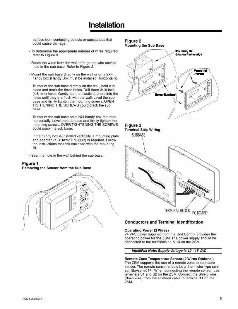
surface from contacting objects or substances thatcould cause damage.
- To determine the appropriate number of wires required,refer to Figure 3.
- Route the wires from the wall through the wire accesshole in the sub base. Refer to Figure 2.
- Mount the sub base directly on the wall or on a 2X4handy box (Handy Box must be installed Horizontally).
To mount the sub base directly on the wall, hold it inplace and mark the three holes. Drill three 3/16 inch(4.8 mm) holes. Gently tap the plastic anchors into theholes until they are flush with the wall. Level the subbase and firmly tighten the mounting screws. OVERTIGHTENING THE SCREWS could crack the subbase.
To mount the sub base on a 2X4 handy box mountedhorizontally, Level the sub base and firmly tighten themounting screws. OVER TIGHTENING THE SCREWScould crack the sub base.
If the handy box is installed vertically, a mounting plateand adapter kit (#BAYMTPL003B) is required. Followthe instructions that are enclosed with the mountingkit.
- Seal the hole in the wall behind the sub base.
Figure 1Removing the Sensor from the Sub Base
Figure 2Mounting the Sub Base
Figure 3Terminal Strip Wiring
O O
O O O
O O
O
O O
O O
A1 A2 A3 7 8 9 10 11 12 14 S1 S 2
SUBBASE
TERMINAL BLOCK PC BOARD
Conductors and Terminal Identification
Operating Power (2 Wires)24 VAC power supplied from the Unit Control provides theoperating power for the ZSM. The power supply should beconnected to the terminals 11 & 14 on the ZSM.
IntelliPak Note: Supply Voltage is 12 - 15 VAC
Remote Zone Temperature Sensor (2 Wires Optional)The ZSM supports the use of a remote zone temperaturesensor. The remote sensor should be a thermistor type sen-sor (Baysens017). When connecting the remote sensor, useterminals S1 and S2 on the ZSM. Connect the Shield wire(drain wire) from the shielded cable to terminal 11 on theZSM.

6 ACC-SVN28A-EN
Installation
Note: When using a remote sensor, Option # 11 inthe OPTION MENU must be set to “1”.
Communication (1 Wire)Data communication between the UCM and the ZSM is ac-complished over a serial link connected at terminal 12 onthe ZSM.
UCM Status Inputs (4 Wires Optional)The ZSM can be wired to receive four (4) operating statussignals from the UCM (HEAT, COOL, SYSTEM “ON”, SER-VICE). Four (4) wires from the UCM should be connectedto the appropriate terminals (7, 8, 9 & 10) on the ZSM.
Auxiliary Relay (3 Wires Optional)The auxiliary relay located on the ZSM is energized duringOCCUPIED periods. The auxiliary relay is form C, rated for1.25 Amps at 30 VAC. Figure 3 illustrates the terminal con-figuration.
Note: Guidelines for wire sizes and lengths areshown in Table 1. The total resistance of these lowvoltage wires must not exceed 2.5 ohms perconductor. Any resistance greater than 2.5 ohmsmay cause the control to malfunction due toexcessive voltage drop.
Note: Do not run low-voltage control wiring in sameconduit with high-voltage power wiring.
Table 1Zone Sensor Maximum Lengths and Wire Size
Feet Meters0 - 150 0 - 46 22 gauge 0.33 mm2
151 - 240 47 - 73 20 gauge 0.50 mm2
241 - 385 74 - 117 18 gauge 0.75 mm2
386 - 610 118 - 185 16 gauge 1.30 mm2
611 - 970 186 - 296 14 gauge 2.00 mm2
Area
Distance fromUnit to Control
RecommendedWire Size
Wiring The Sub Base
Connecting the wires1. Strip approximately ¼ inch of insulation from each wire
and connect the wiring to the appropriate terminals at theunit control panel.
2. Remove the Terminal Block from the hardware package andconnect the wiring to the appropriate terminals at theZone Sensor sub base. In general, zone sensor connec-tions use the convention of connecting Zone Sensor ter-minals to like numbered Unit terminals (1 to 1, 2 to 2,etc.). Refer to Figure 3.
3. Firmly tighten each screw terminal.
4. Attach the terminal block to the Sensor PC Board.
5. Fit the wires as close to the sub base as possible. Besure to push the excess wire into the wall and plug thehole with nonflammable insulation to prevent drafts fromaffecting the sensor.
Note: Do Not Coil Excess Wire Inside Sub Base!Push All Excess Wire Inside Handy Box Or InsideWall Cavity.
6. Replace cover. Place the zone sensor on the sub base byhooking the top two tabs on the Zone Sensor Module tothe slotted tabs on top of the sub base. Swing the ZSMstraight down onto the sub base until you hear the plasticlocking mechanism snap securely into place.
Note: If the wire bundle is large, it may cause theterminal strip to become disconnected. Secure thewires to the sub base using a small wire tie.
Figure 3Zone Sensor Connection Diagram
7ACC-SVN28AEN
Initial Power-Up
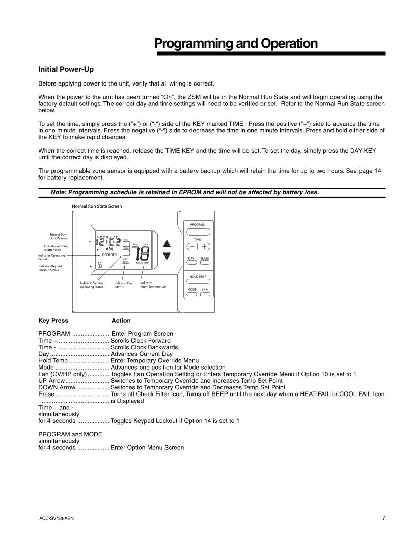
Before applying power to the unit, verify that all wiring is correct.
When the power to the unit has been turned “On”, the ZSM will be in the Normal Run State and will begin operating using thefactory default settings. The correct day and time settings will need to be verified or set. Refer to the Normal Run State screenbelow.
To set the time, simply press the (“+”) or (“-“) side of the KEY marked TIME. Press the positive (“+”) side to advance the timein one minute intervals. Press the negative (“-“) side to decrease the time in one minute intervals. Press and hold either side ofthe KEY to make rapid changes.
When the correct time is reached, release the TIME KEY and the time will be set. To set the day, simply press the DAY KEYuntil the correct day is displayed.
The programmable zone sensor is equipped with a battery backup which will retain the time for up to two hours. See page 14for battery replacement.
Note: Programming schedule is retained in EPROM and will not be affected by battery loss.
TIME
PROGRAM
DAY ERASE
HOLD TEMP
MODE FAN
ROOM TEMPAUTOFAN
HEAT COOL
MODE
COOL
OCCUPIED
Normal Run State Screen
Time of DayHour/Minute
AMIndicates morningor afternoon
Indicates OperatingPeriod
Indicates Keypad Lockout Status
Indicates SystemOperating Status
Indicates Fan Status
Indicates Room Temperature
Key Press Action
PROGRAM ...................... Enter Program ScreenTime + .............................. Scrolls Clock ForwardTime - ............................... Scrolls Clock BackwardsDay ................................... Advances Current DayHold Temp ........................ Enter Temporary Override MenuMode ................................ Advances one position for Mode selectionFan (CV/HP only) ............. Toggles Fan Operation Setting or Enters Temporary Override Menu if Option 10 is set to 1UP Arrow .......................... Switches to Temporary Override and Increases Temp Set PointDOWN Arrow ................... Switches to Temporary Override and Decreases Temp Set PointErase ................................ Turns off Check Filter Icon, Turns off BEEP until the next day when a HEAT FAIL or COOL FAIL Icon......................................... is Displayed
Time + and -simultaneouslyfor 4 seconds ................... Toggles Keypad Lockout if Option 14 is set to 1
PROGRAM and MODEsimultaneouslyfor 4 seconds ................... Enter Option Menu Screen
Programming and Operation
8 ACC-SVN28A-EN
Programming and Operation
Option Menu
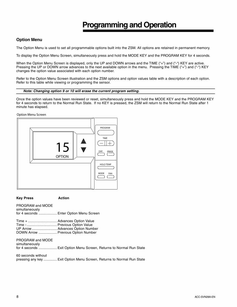
The Option Menu is used to set all programmable options built into the ZSM. All options are retained in permanent memory.
To display the Option Menu Screen, simultaneously press and hold the MODE KEY and the PROGRAM KEY for 4 seconds.
When the Option Menu Screen is displayed, only the UP and DOWN arrows and the TIME (“+”) and (“-“) KEY are active.Pressing the UP or DOWN arrow advances to the next available option in the menu. Pressing the TIME (“+”) and (“-“) KEYchanges the option value associated with each option number.
Refer to the Option Menu Screen illustration and the ZSM options and option values table with a description of each option.Refer to this table while viewing or programming the sensor.
Note: Changing option 9 or 10 will erase the current program setting.
Once the option values have been reviewed or reset, simultaneously press and hold the MODE KEY and the PROGRAM KEYfor 4 seconds to return to the Normal Run State. If no KEY is pressed, the ZSM will return to the Normal Run State after 1minute has elapsed.
TIME
PROGRAM
DAY ERASE
HOLD TEMP
MODE FAN
Option Menu Screen
15OPTION
Key Press Action
PROGRAM and MODEsimultaneouslyfor 4 seconds ................... Enter Option Menu Screen
Time + .............................. Advances Option ValueTime - ............................... Previous Option ValueUP Arrow.......................... Advances Option NumberDOWN Arrow ................... Previous Option Number
PROGRAM and MODEsimultaneouslyfor 4 seconds ................... Exit Option Menu Screen, Returns to Normal Run State
60 seconds withoutpressing any key .............. Exit Option Menu Screen, Returns to Normal Run State

9ACC-SVN28AEN
Option Function Option Value Default Description1 Morning warm-up 0 = Disabled
1 = Enabled0 When enabled, Heat is turned on if the Zone temperature is 2
degrees below the heat set point temperature when the program switches from unoccupied to occupied. The heat will terminate after 60 minutes regardless if the set point has been reached.
2 Economizer minimum position override
0 = Disabled1 = Enabled
1 When enabled, the minimum position of the economizer damper is overridden during the unoccupied period.
3 Temperature Scale 0 = Fahrenheit1 = Centigrade
0 Displays the temperature in the selected format.
4 Supply Air Tempering 0 = Disabled1 = Enabled
0 When enabled, sends the tempering signal to the UCP.
5 Time Clock 0 = 12 hour1 = 24 hour
0 Sets Clock to 12 hour format with AM and PM or 24 hour military time.
6 Smart Fan 0 = Disabled1 = Enabled
1 When enabled, the supply fan operates in the AUTO mode during unoccupied periods regardless of FAN setting.
7 Intelligent Temperature Recovery
0 = Disabled1 = Enabled
0 When enabled, offsets the set point temperature and starts the system before the scheduled occupied period to efficiently reach the occupied temperature set point. The time is calculated based on a recovery rate of 6 degrees per hour. If option 19 is set for HP, this option is disabled during EMERgency heat operation.
8 Programmable Days/Week
0 = 7 days (M, T, W, T, F, S, S)
1 = 3 days (M-F, S, S)2 = 2 days (M-F, S-S)3 = 1 day (Sun-Sat)
0 0 allows all 7 days to be individually programmed. 1 allows Mon - Fri, Sat & Sun to be programmed separately. 2 allows Mon - Fri and Sat - Sun to be programmed the same. 3 uses the same program for each day of the week.
9 Programmable Periods/Day
2, 3, 4 4 If 2 is selected, only Day and Nite periods can be programmed. If 3 is selected, Morn, Day, and Nite can be programmed. If 4 is selected, Morn, Day, Eve, and Nite can be programmed.
10 Programmable Fan Operation
0 = Disallowed1 = Allowed
0 If allowed, Supply Fan operation can be programmed for On or Auto operation for each programmed period.
11 Remote Sensor Installed 0 = No1 = Yes
0 Determines which source will supply the Room Temperature input for display.
12 Check Filter Interval 0 = Disabled3000 to 50 in 50 hour
increments
350 Adjustable in 50 hour increments. The CHECK FILTER icon will flash when the accumulated run time is greater than the interval setting.
13 Display Zone Temperature
0 = No1 = Yes
1 If ZSM is in a Normal Run State or in Temporary Override, the zone temperature will be displayed.
14 Keypad Lockout Enabled 0 = Disabled1 = Enabled
1 When Enabled, Keypad can be locked out.
15 Default Temporary Override Time
1, 2, 3, 4, 5 3 Sets the default override time in hours.
16 Buzzer Options 0 = Key Press Only1 = Key Press and Check
Filter2 = Key Press, Check
Filter, and System Failure
1 Buzzer will sound for a 1/2 sec for every minute if option is set for 1 or 2.
17 Zone Temperature Calibration
Zone Temperature Displayed
0 offset This allows for field calibration in 1.0 degree increments of either the internal sensor on the ZSM or the remote sensor if used.
18 Baud Rate 0 = 1024 baud1 = 1200 baud
1 Set to Zero for 3 - 25 Ton Voyager Units built before Jan. 1, 1996 that have the original UCP.
19 CV or HP Operation 0 = CV1 = HP
0 This sets the operation MODE for the ZSM. If HP is selected, EMERgency heat is available.
20 Default Cooling Set Point 45 to 98 74 If no set point has been programmed or the program is lost, the value set here becomes the operation set point.
21 Default Heating Set Point 43 to 96 68 If no set point has been programmed or the program is lost, the value set here becomes the operation set point.
22 Minimum Cooling Set Point
45 to 98 45 Sets the minimum programmable cooling temperature set point.
23 Maximum Heating Set Point
43 to 96 96 Sets the maximum programmable heating temperature set point.
Programming and Operation
10 ACC-SVN28A-EN
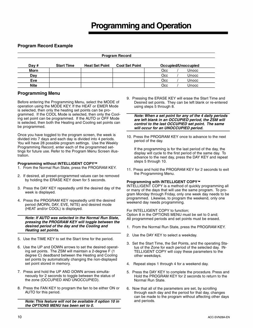
Program Record Example
Program Record
Day # Start Time Heat Set Point Cool Set Point Occupied/UnoccupiedMorn Occ / UnoccDay Occ / UnoccEve Occ / UnoccNite Occ / Unocc
Programming and Operation
Programming Menu
Before entering the Programming Menu, select the MODE ofoperation using the MODE KEY. If the HEAT or EMER Modeis selected, then only the heating set points can be pro-grammed. If the COOL Mode is selected, then only the Cool-ing set point can be programmed. If the AUTO or OFF Modeis selected, then both the Heating and Cooling set points canbe programmed.
Once you have toggled to the program screen, the week isdivided into 7 days and each day is divided into 4 periods.You will have 28 possible program settings. Use the WeeklyProgramming Record, enter each of the programmed set-tings for future use. Refer to the Program Menu Screen illus-tration.
Programming without INTELLIGENT COPY�1. From the Normal Run State, press the PROGRAM KEY.
2. If desired, all preset-programmed values can be removedby holding the ERASE KEY down for 5 seconds.
3. Press the DAY KEY repeatedly until the desired day of theweek is displayed.
4. Press the PROGRAM KEY repeatedly until the desiredperiod (MORN, DAY, EVE, NITE) and desired mode(HEAT and/or COOL) is displayed.
Note: If AUTO was selected in the Normal Run State,pressing the PROGRAM KEY will toggle between thedesired period of the day and the Cooling andHeating set points.
5. Use the TIME KEY to set the Start time for the period.
6. Use the UP and DOWN arrows to set the desired operat-ing set points. The ZSM will maintain a 2-degree F (1degree C) deadband between the Heating and Coolingset points by automatically changing the non-displayedset point stored in memory.
7. Press and hold the UP AND DOWN arrows simulta-neously for 2 seconds to toggle between the status ofthe zone (OCCUPIED AND UNOCCUPIED).
8. Press the FAN KEY to program the fan to be either ON orAUTO for this period.
Note: This feature will not be available if option 10 inthe OPTIONS MENU has been set to 0.
9. Pressing the ERASE KEY will erase the Start Time andDesired set points. They can be left blank or re-enteredusing steps 5 through 8.
Note: When a set point for any of the 4 daily periodsare left blank in an OCCUPIED period, the ZSM willcontrol to the last OCCUPIED set point. The samewill occur for an UNOCCUPIED period.
10. Press the PROGRAM KEY once to advance to the nextperiod of the day.
If the programming is for the last period of the day, thedisplay will cycle to the first period of the same day. Toadvance to the next day, press the DAY KEY and repeatsteps 5 through 10.
11. Press and hold the PROGRAM KEY for 2 seconds to exitthe Programming Menu.
Programming with INTELLIGENT COPY�INTELLIGENT COPY is a method of quickly programming allor many of the days that will use the same program. To pro-gram Monday through Friday, only one week day needs to beprogrammed. Likewise, to program the weekend, only oneweekend day needs programming.
For INTELLIGENT COPY to function;Option 8 in the OPTIONS MENU must be set to 0 and;All programmed periods and set points must be erased.
1. From the Normal Run State, press the PROGRAM KEY.
2. Use the DAY KEY to select a weekday.
3. Set the Start Time, the Set Points, and the operating Sta-tus of the Zone for each period of the selected day. IN-TELLIGENT COPY will copy these parameters to theother weekdays.
4. Repeat steps 1 through 4 for a weekend day.
5. Press the DAY KEY to complete the procedure. Press andHold the PROGRAM KEY for 2 seconds to return to theNormal Run State.
6. Now that all of the parameters are set, by scrollingthrough each day and the period for that day, changescan be made to the program without affecting other daysand periods.
11ACC-SVN28AEN
TIME
PROGRAM
DAY ERASE
HOLD TEMP
MODE FAN
ROOM TEMPAUTOFAN
HEAT
MODE
COOL
OCCUPIED
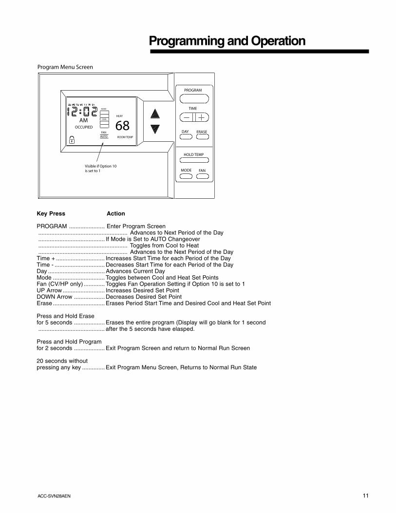
Program Menu Screen
AM
Visible if Option 10 is set to 1
68
Key Press Action
PROGRAM ...................... Enter Program Screen....................................................... Advances to Next Period of the Day......................................... If Mode is Set to AUTO Changeover....................................................... Toggles from Cool to Heat....................................................... Advances to the Next Period of the Day
Time + .............................. Increases Start Time for each Period of the DayTime - ............................... Decreases Start Time for each Period of the DayDay ................................... Advances Current DayMode ................................ Toggles between Cool and Heat Set PointsFan (CV/HP only) ............. Toggles Fan Operation Setting if Option 10 is set to 1UP Arrow .......................... Increases Desired Set PointDOWN Arrow ................... Decreases Desired Set PointErase ................................ Erases Period Start Time and Desired Cool and Heat Set Point
Press and Hold Erasefor 5 seconds ................... Erases the entire program (Display will go blank for 1 second......................................... after the 5 seconds have elasped.
Press and Hold Programfor 2 seconds ................... Exit Program Screen and return to Normal Run Screen
20 seconds withoutpressing any key .............. Exit Program Menu Screen, Returns to Normal Run State
Programming and Operation
12 ACC-SVN28A-EN
Temporary Override Menu
The Temporary Override Menu is used to change tempera-ture set points, Mode of Operation, and the Zone status (OC-CUPIED or UNOCCUPIED) for a designated length of timewithout having to change what typically would be the NormalProgram. If Option 10 is set to 1, then the Fan Mode will bedisplayed and programmable. Refer to the Temporary Over-ride Menu screen illustration.
Note: Changing option 9 or 10 will erase the currentprogram setting.
To enter the Temporary Override Menu;
1. From the Normal Run State, press the HOLD TEMP KEYor either the UP or DOWN KEY.
2. The HOURS icon located under the right two digits of theclock will be blinking. Press the Positive (“+”) side of theTIME KEY to increase the number of hours the overrideprogram will last. Press the Negative (“-”) side of theTIME KEY to decrease the number of hours.
3. Press the DAY KEY to toggle from the Hours icon to theDays icon. Press the Positive (“+”) side of the TIME KEYto increase the number of days the override program willlast. Press the Negative (“-”) side of the TIME KEY todecrease the number of days.
4. Press the UP or DOWN arrows to program the tempera-ture set points (HEAT and/or COOL). Use the MODEKEY to toggle between the Modes if applicable.
5. Press the FAN KEY to program the fan for ON or AUTOoperation during the override period.
6. Press and hold the UP and DOWN arrows simulta-neously for 2 seconds to toggle the zone status betweenOCCUPIED and UNOCCUPIED.
7. Pressing the ERASE KEY will cancel any override pro-gramming and return the sensor to the Normal RunState.
8. Press the HOLD TEMP KEY to confirm the program andto start Temporary Override. If no keys are pressed, thesensor will return to the Normal Run State and ignorethe override program.
9. Press and hold the Positive (“+”) and Negative (“-”) keyssimultaneously for 5 seconds to lock key pad.
Press and hold the Positive (“+”) and Negative (“-”) keyssimultaneously for 5 seconds to unlock key pad.
Programming and Operation
Entering the Temporary Override ScreenOnce the override program has begun and the Keypad Lock-out is disabled, the MODE KEY will allow the operator tochange the System Mode. The ERASE KEY can only beused to cancel the CHECK FILTER signal if displayed. TheFAN KEY will exit the Temporary Override Program and enterthe Temporary Override Menu screen. All other keys are dis-abled. Refer to the Temporary Override screen illustration.
To Exit the Temporary Override program;
1. Press either of the UP or DOWN arrows, the HOLD TEMPKEY, or the FAN KEY. (Returns sensor to the TemporaryOverride Menu)
2. To change the program parameters, refer to the previousprogramming steps 2 through 8.
3. To return to the Normal Run State from the TemporaryOverride Menu, press the ERASE KEY.
13ACC-SVN28AEN
Programming and Operation
TIME
PROGRAM
DAY ERASE
HOLD TEMP
MODE FAN
AUTOFAN
HEAT
MODE
COOL
OCCUPIED
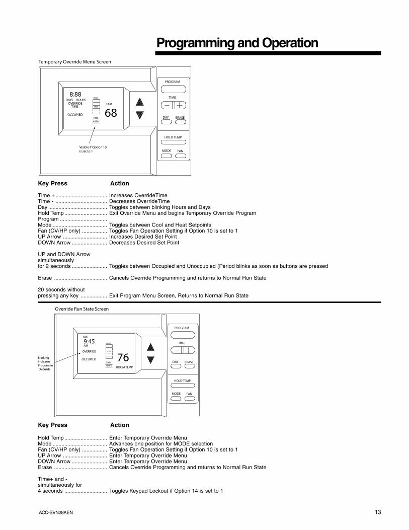
Temporary Override Menu Screen
Visible if Option 10 is set to 1
68
8:88DAYS HOURS
OVERRIDETIME
Key Press Action
Time + ................................... Increases OverrideTimeTime - ................................... Decreases OverrideTimeDay ........................................ Toggles between blinking Hours and DaysHold Temp............................. Exit Override Menu and begins Temporary Override ProgramProgram ................................Mode ..................................... Toggles between Cool and Heat SetpointsFan (CV/HP only) ................. Toggles Fan Operation Setting if Option 10 is set to 1UP Arrow .............................. Increases Desired Set PointDOWN Arrow ........................ Decreases Desired Set Point
UP and DOWN Arrowsimultaneouslyfor 2 seconds ........................ Toggles between Occupied and Unoccupied (Period blinks as soon as buttons are pressed
Erase .................................... Cancels Override Programming and returns to Normal Run State
20 seconds withoutpressing any key .................. Exit Program Menu Screen, Returns to Normal Run State
TIME
PROGRAM
DAY ERASE
HOLD TEMP
MODE FAN
AUTOFAN
MODE
COOL
OCCUPIED
Override Run State Screen
Blinking indicates Program in Override
76
9:45
OVERRIDE
ROOM TEMP
AM
Mo
Key Press Action
Hold Temp............................. Enter Temporary Override MenuMode ..................................... Advances one position for MODE selectionFan (CV/HP only) ................. Toggles Fan Operation Setting if Option 10 is set to 1UP Arrow .............................. Enter Temporary Override MenuDOWN Arrow ........................ Enter Temporary Override MenuErase .................................... Cancels Override Programming and returns to Normal Run State
Time+ and -simultaneously for4 seconds ............................. Toggles Keypad Lockout if Option 14 is set to 1
14 ACC-SVN28A-EN
Zone Sensor Status Indicators
The Unit Control Processor has the capability ofcommunicating four input signals (HEAT, COOL, ON,SERVICE) to the respective Zone Sensor Module (ZSM)icons when appropriately wired.
Each of these Zone Sensor icons will respond to theController in 1 of 3 conditions;
OFF – No icon will be displayed when the unit is notoperating.
ON – Indicates that the unit is operating in the Modereflected by the illuminated icon.
FLASHING – Indicates that the system is not operatingproperly and some type of service may be required.
The Controller Status Input conditions and the respectivezone sensor terminals are;
Terminal # 7 – (HEAT Icon)ON – Indicates by a continuously illuminated icon
that the unit is operating in the Heating Mode.FLASHING – The HEAT FAILURE icon indicates
that a system failure in the Heating Mode hasoccurred.
Terminal # 8 – (COOL Icon)ON – Indicates by a continuously illuminated icon
that the unit is operating in the Cooling Mode.FLASHING – The COOL FAILURE icon indicates
that a system failure in the Cooling Mode hasoccurred.
Terminal # 9 – (ON Icon)OFF – The Colon (:) displayed in the Clock is not
flashing, the System is OFF.ON – The Colon (:) displayed in the Clock is
flashing, the System is ON.FLASHING – The TEST icon indicates the System is
operating in the Test Mode.Terminal # 10 – (SERVICE Icon)
ON - Indicates by a continuously illuminated iconthat the unit requires service.
FLASHING – Indicates that a Fan Failure hasoccurred and service is required.
Note 1: Voyager 27.5 - 50 Ton - For CombinationDiagnostics (ie. Cool Fail plus Heat Fail) See Unit IOMor Diagnostics Label on the unit control box door.
If number 2 is selected for option 16 in the Options Menu,any of the FLASHING signals will sound an audible buzzer.To reset the buzzer, press the ERASE Key.
Programming and Operation
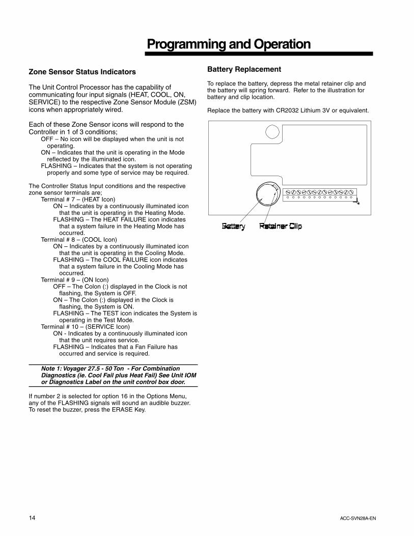
Battery Replacement
To replace the battery, depress the metal retainer clip andthe battery will spring forward. Refer to the illustration forbattery and clip location.
Replace the battery with CR2032 Lithium 3V or equivalent.
15ACC-SVN28AEN
Programming and Operation
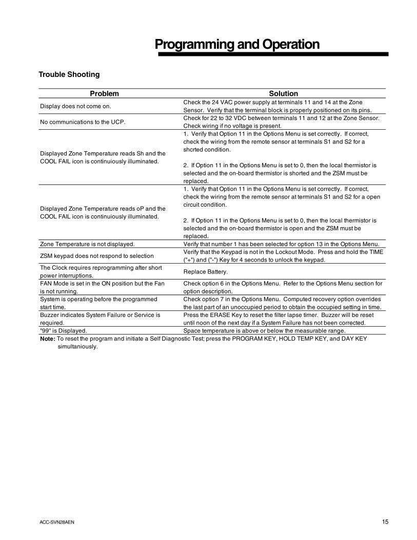
Trouble Shooting
Problem Solution
Display does not come on.Check the 24 VAC power supply at terminals 11 and 14 at the Zone Sensor. Verify that the terminal block is properly positioned on its pins.
No communications to the UCP.Check for 22 to 32 VDC between terminals 11 and 12 at the Zone Sensor. Check wiring if no voltage is present.
Displayed Zone Temperature reads Sh and the COOL FAIL icon is continuiously illuminated.
1. Verify that Option 11 in the Options Menu is set correctly. If correct, check the wiring from the remote sensor at terminals S1 and S2 for a shcrted condition.
2. If Option 11 in the Options Menu is set to 0, then the local thermistor is selected and the on-board thermistor is shorted and the ZSM must be replaced.
Displayed Zone Temperature reads oP and the COOL FAIL icon is continuiously illuminated.
1. Verify that Option 11 in the Options Menu is set correctly. If correct, check the wiring from the remote sensor at terminals S1 and S2 for a open circuit condition.
2. If Option 11 in the Options Menu is set to 0, then the local thermistor is selected and the on-board thermistor is open and the ZSM must be replaced.
Zone Temperature is not displayed. Verify that number 1 has been selected for option 13 in the Options Menu.
ZSM keypad does not respond to selectionVerify that the Keypad is not in the Lockout Mode. Press and hold the TIME ("+") and ("-") Key for 4 seconds to unlock the keypad.
The Clock requires reprogramming after short power interruptions.
Replace Battery.
FAN Mode is set in the ON position but the Fan is not running.
Check option 6 in the Options Menu. Refer to the Options Menu section for option description.
System is operating before the programmed start time.
Check option 7 in the Options Menu. Computed recovery option overrides the last part of an unoccupied period to obtain the occupied setting in time.
Buzzer indicates System Failure or Service is required.
Press the ERASE Key to reset the filter lapse timer. Buzzer will be reset until noon of the next day if a System Failure has not been corrected.
"99" is Displayed. Space temperature is above or below the measurable range.Note: To reset the program and initiate a Self Diagnostic Test; press the PROGRAM KEY, HOLD TEMP KEY, and DAY KEY simultaniously.

16 ACC-SVN28A-EN
The manufacturer has a policy of continuous product and product data improvement and reserves the rightto change design and specifications without notice.
Literature Order Number
File Number
Supersedes
Stocking Location
ACC-SVN28A-EN
SV-UN-ACC-ACC-SVN28A-EN
New
Webb Mason