INSTALLER MANUAL - satel.pl · detector is to occupy one or two positions on the list of wireless...
33
SATEL sp. z o.o. ul. Budowlanych 66 80-298 Gdańsk POLAND tel. + 48 58 320 94 00 www.satel.eu integra_i_en 05/17 Firmware version 1.17 Alarm Control Panels INSTALLER MANUAL
Transcript of INSTALLER MANUAL - satel.pl · detector is to occupy one or two positions on the list of wireless...

SATEL sp. z o.o. ul. Budowlanych 66
80-298 Gdańsk POLAND
tel. + 48 58 320 94 00 www.satel.eu
integra_i_en 05/17
Firm
war
e v
ersi
on 1
.17
A
larm
Con
trol
Pan
els
INSTALLER MANUAL

WARNINGS
The security alarm system should be installed by qualified personnel.
Prior to installation, please read carefully this manual in order to avoid mistakes that can lead to malfunction or even damage to the equipment.
Disconnect power before making any electrical connections.
Changes, modifications or repairs not authorized by the manufacturer shall void your rights under the warranty.
SATEL's goal is to continually upgrade the quality of its products, which may result in some changes of their technical specifications and firmware. The current information on
the introduced modifications is available on our website. Please visit us:
http://www.satel.eu
The declaration of conformity may be consulted at www.satel.eu/ce
The following symbols may be used in this manual:
- note;
- caution.

Changes made to the firmware version 1.17
Zones The output cut-off time can be programmed with an accuracy of up to 0.1 second.
Options Changed names of options:
DO NOT REPORT SATEL SERVER TROUBLE has been replaced with DO
NOT REPORT SATEL SERVER CONNECTION TROUBLE,
DO NOT REPORT TIME SERVER TROUBLE has been replaced with DO NOT
REPORT TIME SERVER CONNECTION TROUBLE.
Keypads Changed names of parameters:
SHOW ENTRY DELAY OF PARTITIONS has been replaced with DISPLAY
ENTRY DELAY OF PARTITIONS,
SHOW EXIT DELAY OF PARTITIONS has been replaced with DISPLAY EXIT
DELAY OF PARTITIONS.
New parameters:
SIGNAL ENTRY DELAY OF PARTITIONS,
SIGNAL EXIT DELAY OF PARTITIONS.
Deleted options:
SIGN. ENTRY DELAY,
SIGN. EXIT DELAY.
Wireless devices
If the ACU-120 / ACU-270 controller with firmware version 5.03 is connected to the control panel, you can select whether the AMD-101 detector is to occupy one or two positions on the list of wireless devices.

2 Installer Manual SATEL
CONTENTS
1. General .............................................................................................................................3 2. Features............................................................................................................................3 3. Keypads............................................................................................................................6
3.1 Features of keypads with mechanical keys ...............................................................6 4. Expansion modules...........................................................................................................7
4.1 Modules to be connected to the keypad bus .............................................................7 4.2 Modules to be connected to the expander bus ...........................................................7
5. System installation ............................................................................................................9 5.1 Installation plan..........................................................................................................9 5.2 Estimation of the system current consumption ..........................................................9 5.3 Cabling ....................................................................................................................10 5.4 Installation of control panel mainboard ....................................................................10
5.4.1 Description of the mainboards ..........................................................................11 5.5 Connecting devices to the keypad bus ....................................................................14
5.5.1 Addressing devices connected to the keypad bus............................................15 5.5.2 Numeration of keypad zones ............................................................................16 5.5.3 Connecting computer to the keypad RS-232 port.............................................17
5.6 Connecting devices to the expander bus.................................................................17 5.6.1 Connecting the INT-VG or INT-AV module or CA-64 SM expander .................18 5.6.2 Addressing devices connected to the expander bus ........................................18
5.7 Connecting the detectors.........................................................................................19 5.7.1 End-of-line resistors..........................................................................................20
5.8 Connecting the sirens ..............................................................................................20 5.9 Connecting the telephone line .................................................................................20 5.10 Connecting power supply ........................................................................................21
5.10.1 Main power supply............................................................................................21 5.10.2 Backup power supply .......................................................................................22 5.10.3 Control panel power-up / start-up procedure ....................................................22
5.11 First start-up of the control panel .............................................................................23 5.12 Emergency procedure of the control panel start-up .................................................23 5.13 Connecting computer to the control panel ...............................................................24 5.14 Connecting the external modem..............................................................................24
5.14.1 Configuring settings of the modem to be connected to control panel ...............26 5.15 Connecting the printer .............................................................................................27
6. Numeration of zones and outputs in the system .............................................................28 7. Specifications..................................................................................................................29
7.1 Control panel ...........................................................................................................29 7.2 INT-KLCD keypad....................................................................................................30 7.3 INT-KLCDR keypad .................................................................................................30 7.4 INT-KLCDL keypad..................................................................................................30 7.5 INT-KLCDS keypad .................................................................................................30 7.6 INT-KLCDK keypad .................................................................................................30 7.7 INT-KLFR keypad ....................................................................................................31
8. Manual update history.....................................................................................................31

SATEL INTEGRA 3
1. General
This manual applies to the control panels of the INTEGRA series:
– INTEGRA 24
– INTEGRA 32
– INTEGRA 64
– INTEGRA 128
The manual also describes keypads compatible with the INTEGRA control panels and other devices that may be included in the security alarm system.
The INTEGRA control panels meet the requirements of the following standards: – EN 50131-1 Grade 2, – EN 50131-3 Grade 2, – EN 50131-6 Grade 2, – EN 50130-4, – EN 50130-5 Class II.
2. Features
System structure Number of partitions:
– up to 4 (INTEGRA 24),
– up to 16 (INTEGRA 32),
– up to 32 (INTEGRA 64 and INTEGRA 128).
Number of objects (subsystems):
– 1 (INTEGRA 24),
– up to 4 (INTEGRA 32),
– up to 8 (INTEGRA 64 and INTEGRA 128).
Zones 4 (INTEGRA 24), 8 (INTEGRA 32) or 16 (INTEGRA 64 and INTEGRA 128) programmable
hardwired zones on the control panel mainboard:
– support for NO and NC type detectors, as well as roller shutter and vibration detectors,
– support for Single EOL and Double EOL configuration,
– several dozen zone types.
Maximum number of programmable zones:
– up to 24 (INTEGRA 24),
– up to 32 (INTEGRA 32),
– up to 64 (INTEGRA 64),
– up to 128 (INTEGRA 128).
Outputs 4 (INTEGRA 24), 8 (INTEGRA 32) or 16 (INTEGRA 64 and INTEGRA 128) programmable
hardwired outputs on the control panel mainboard:
– 2 (INTEGRA 24 and INTEGRA 32) or 4 (INTEGRA 64 and INTEGRA 128) high-current outputs,

4 Installer Manual SATEL
– 2 (INTEGRA 24), 6 (INTEGRA 32) or 12 (INTEGRA 64 and INTEGRA 128) low-current outputs, OC type,
– over 100 functions,
– execution of custom control functions due to the possibility of programming complex logic operations on the outputs.
Maximum number of programmable outputs: – 24 (INTEGRA 24) [20 physically available outputs (mainboard + expansion modules)
and 4 virtual outputs],
– 32 (INTEGRA 32),
– 64 (INTEGRA 64),
– 128 (INTEGRA 128).
Additional high-current outputs, functioning as power supply outputs:
– 3 (INTEGRA 24 and INTEGRA 32),
– 2 (INTEGRA 64 and INTEGRA 128) [the power supply output for powering the expanders has 2 terminals].
Communication buses Keypad bus for connecting:
– up to 4 devices (INTEGRA 24 and INTEGRA 32),
– up to 8 devices (INTEGRA 64 and INTEGRA 128).
1 (INTEGRA 24 and INTEGRA 32) or 2 (INTEGRA 64 and INTEGRA 128) expander buses for connecting:
– up to 32 devices (INTEGRA 24 and INTEGRA 32),
– up to 64 devices (INTEGRA 64 and INTEGRA 128) – 32 devices to each bus.
Communication Telephone dialer (communicator) to allow:
– events reporting,
– event messaging,
– checking the alarm system status by telephone (DTMF),
– remote control of the alarm system outputs by telephone (DTMF).
Built-in 300 bps modem to allow remote operation and programming of the alarm system.
Reporting events to two monitoring stations: – several communication formats (including Contact ID and SIA),
– 4 telephone numbers (2 main + 2 backup ones),
– 9 identifiers.
Alternative ways to report events available after additional modules are connected:
– Ethernet (TCP or UDP),
– GPRS (TCP lub UDP),
– GSM voice channel.
Event messaging to 4 (INTEGRA 24), 8 (INTEGRA 32) or 16 (INTEGRA 64 and INTEGRA 128) phone numbers in the form of:
– voice messages played back by an additional module (INT-VG, CA-64 SM or SM-2),
– text messages defined by the installer.

SATEL INTEGRA 5
Event log 439 (INTEGRA 24 and INTEGRA 32), 5887 (INTEGRA 64) or 22527 (INTEGRA 128)
events.
A separate memory space to store events required by the EN 50131 standard for Grade 2.
Event log printing capability.
Users 1 (INTEGRA 24), 4 (INTEGRA 32) or 8 (INTEGRA 64 and INTEGRA 128) master users
(administrators).
16 (INTEGRA 24), 64 (INTEGRA 32), 192 (INTEGRA 64) or 240 (INTEGRA 128) users.
Capability to assign to the user: – a code,
– a proximity card (125 kHz passive transponder, which may be in the form of a card, tag, etc.),
– DALLAS iButton (chip),
– keyfob.
Several user types.
Authority level determining the scope of access to the system.
Additional features Access control functions realized by means of additional modules.
16 (INTEGRA 24), 28 (INTEGRA 32) or 64 (INTEGRA 64 and INTEGRA 128) timers programmed by the installer to automatically:
– arm/disarm the partitions,
– control the outputs (switching the lights on/off, watering the garden, etc.).
Partition timers (1 for each partition) to automatically arm/disarm the partitions.
Programming Local programming:
– keypad,
– computer with the DLOADX program installed, connected to the control panel RS-232 port.
Remote programming: – computer with the DLOADX program installed, communicating via the telephone
network or via the Ethernet network (optionally, if the ETHM-1 / ETHM-1 Plus module is connected),
– internet browser (optionally, if the ETHM-1 / ETHM-1 Plus module is connected),
– mobile phone with suitable application installed (optionally, if the ETHM-1 / ETHM-1 Plus module is connected).
Mainboard RS-232 port (RJ type socket) to allow:
– local programming by means of a computer with the DLOADX program installed,
– local system administration by means of a computer with the GUARDX program installed,
– remote programming using the DLOADX program via Ethernet (TCP/IP), if the ETHM-1 / ETHM-1 Plus module is connected,

6 Installer Manual SATEL
– support for external analog, GSM or ISDN modem,
– serial printer connection (for printing current events).
Capability of the firmware updating without the need for disassembly of the control panel.
1 (INTEGRA 24 and INTEGRA 32) or 2 (INTEGRA 64 and INTEGRA 128) sockets for connecting the INT-VG voice module, CA-64 SM voice synthesizers expander or SM-2 synthesizer.
Real time clock with calendar and battery backup.
LEDs indicating the status of outputs, battery charging system and telephone dialer.
Electrical protection of all hardwired zones and outputs, and communication buses.
Switching power supply with short-circuit protection, provided with a battery status supervision and low battery disconnect system.
3. Keypads
The INTEGRA control panels support the following keypads:
INT-TSG – touchscreen keypad,
INT-TSH – touchscreen keypad,
INT-TSI – touchscreen keypad,
INT-KSG – LCD keypad with touch keys,
INT-KLCD – LCD keypad with mechanical keys,
INT-KLCDR – LCD keypad with mechanical keys and built-in proximity card reader,
INT-KLCDK – LCD keypad with mechanical keys,
INT-KLCDL – LCD keypad with mechanical keys,
INT-KLCDS – LCD keypad with mechanical keys,
INT-KLFR – LCD keypad with mechanical keys and built-in proximity card reader.
The recommended version of the keypad firmware (provides functionality consistent with the requirements of EN 50131 for Grade 2):
INT-KLCD / INT-KLCDR – 1.08 (or later),
INT-KLCDK / INT-KLCDL / INT-KLCDS – 6.08 (or later),
INT-KSG – 1.02 (or later).
The keypads are available in a variety of color options for the enclosure, display and key backlight. The color variant is indicated by the additional designation in the keypad name (e.g. INT-KLCD-GR – green display and key backlight; INT-KLCD-BL – blue display and key backlight).
For information on INT-KSG, INT-TSG, INT-TSH and INT-TSI keypads, please refer to the manuals delivered with respective keypads.
3.1 Features of keypads with mechanical keys
Display 2 x 16 characters with backlight.
LEDs indicating the status of the partitions and the system.
Backlit keys.
Built-in sounder.
2 programmable hardwired zones: – support for NO and NC detectors,
SATEL INTEGRA 7
– support for Single EOL and Double EOL configuration.
Tamper protection in 2 ways – cover removal and tearing enclosure from the wall.
RS-232 port (PIN-5 socket) for administration of the security alarm system by means of a computer with the GUARDX program installed.
4. Expansion modules
The expansion modules allow you to not only increase the number of available zones and outputs (wired and wireless), but also enhance the system with additional functionality.
Not all of the following modules meet the requirements of EN 50131 for Grade 2.
4.1 Modules to be connected to the keypad bus
CA-64 PTSA. Mimic board. Enables visualization of the status of the alarm system partitions and zones. The control panels support the mimic boards with electronics version 1.4 (or later) and firmware version 4.0 (or later).
ETHM-1 Plus / ETHM-1. Ethernet communication module. Enables reporting events as well as operating and programming the control panel via the Ethernet network. The recommended module version: 1.06 (or later).
INT-RS / INT-RS Plus. Interface for systems integration. Makes it possible to connect the computer with the GUARDX program installed in the same way as to the LCD keypad, report events through a special external device, or operate the control panel using software other than that offered by SATEL.
4.2 Modules to be connected to the expander bus
INT-RX / INT-RX-S. 433 MHz keyfobs receiver expansion module. Enables operation of the alarm system using the 433 MHz keyfobs.
INT-CR. Proximity card arm/disarm device. Enables arming / disarming and alarm clearing in many partitions by means of proximity cards, proximity tags and other passive transponders.
INT-S / INT-SF / INT-SK. Partition keypad. Enables arming / disarming and alarm clearing in one partition. Can perform access control functions.
INT-SCR. Multifunctional keypad. It can work as:
INT-S. Partition keypad. INT-SCR. Partition keypad with reader. Functionality similar to that of the partition
keypad.
INT-ENT. Entry keypad. The main task of the entry keypad is activation the delay for 3 INTERIOR DELAYED type zones. After expiry of the time period preset on the keypad, unless the system is disarmed, the interior delayed zones will again act as instant ones.
INT-SZ / INT-SZK. Code lock. Enables performance of the access control functions.
INT-R. Universal expander for card / chip readers. Supports the proximity card readers manufactured by SATEL, readers with WIEGAND 26 interface or DALLAS chip readers. Enables performance of the access control functions.
INT-E / CA-64 E / CA-64 EPS. Zone expander. Adds 8 programmable hardwired zones to the security system.
INT-ADR / CA-64 ADR. Addressable zone expander. Adds 48 addressable zones to the security system. Control panels support the addressable zone expanders with firmware version 1.5 (or later).

8 Installer Manual SATEL
Fig
. 1.
IN
TE
GR
A s
ecur
ity a
larm
sys
tem
.

SATEL INTEGRA 9
INT-O / INT-ORS / CA-64 O / CA-64 OPS. Output expander. Adds 8 programmable hardwired outputs to the security system.
INT-PP / INT-IORS / CA-64 PP. Zone/output expander. Adds 8 programmable hardwired zones and 8 programmable hardwired outputs to the security system.
ACU-120 / ACU-270 / ACU-100 / ACU-250. ABAX wireless system controller. Enables the alarm system to be operated using the ABAX keyfobs and the ABAX bidirectional wireless devices to be used in the alarm system.
INT-VG. Voice module. Allows remote operation of the control panel from the telephone keypad (interactive voice menu). It can store 16 voice messages for telephone messaging.
INT-VMG. Voice message generator. Plays back prerecorded messages when specified events occur in the system.
INT-AV. Audio alarm verification module. Enables remote audio alarm verification to eliminate false alarms.
INT-KNX / INT-KNX-2. KNX integration module. Enables interfacing of the control panel with the KNX system.
5. System installation
Disconnect power before making any electrical connections.
The following tools will be useful during installation:
blade screwdriver 2.5 mm,
Phillips screwdriver,
precision pliers,
flat nose pliers,
driller c/w a set of drill bits.
5.1 Installation plan
The installation must be preceded by preparation of a plan of the security alarm system. It is advisable to draw up a sketch of the premises and mark on it all the devices that are to be included in the alarm system: control panel, keypads, detectors, sirens, expansion modules etc. The control panel and other alarm system components should be installed within the protected area.
When writing data to FLASH memory and when the STARTER program is running (control panel firmware is being updated), the expander outputs are deactivated. The status of the control panel mainboard outputs remains unchanged. Keep that in mind when designing the system. It is recommended that devices whose operation must not be disturbed as a result of writing data to FLASH memory or after launching the STARTER program be connected to the mainboard outputs.
5.2 Estimation of the system current consumption
At the security system planning stage you should sum up the currents consumed by all devices included in the system (control panel mainboard, keypads, additional modules, detectors, sirens, etc.). The calculation should take into account the battery charging current. If the sum of currents exceeds the maximum output current of the control panel power supply, expander with power supply or an additional power supply unit should be used.

10 Installer Manual SATEL
The sum of currents consumed by the devices connected to the power supply unit (expander with power supply) must not exceed the power supply output current.
If you plan to connect devices to particular power outputs (of the control panel, expander with power supply, etc.), remember that the sum of currents consumed by these devices must not exceed the maximum current carrying capacity of those outputs.
5.3 Cabling
It is recommended that unscreened straight-through cable be used for making electric connections between devices included in the system (using the twisted-pair type of cable, e.g. UTP, STP, FTP, is not advisable).
If you use the twisted-pair type of cable, remember that the DTM and CKM / DT and CK / DT1 and CK1 / DT2 and CK2 (data and clock) signals must not be sent through one twisted-pair cable.
It is recommended that separate cables be used for keypad bus and expander bus.
Select cross-section of the power supply wires so that the supply voltage drop between the power supply and the supplied device should not exceed 1 V as against the output voltage.
In order to guarantee correct functioning of the system components it is important that resistance and capacitance of the signal wires be as low as possible. When the distances between the devices are greater, several wires connected in parallel may have to be used for each signal, in order to reduce conductor resistance. This, however, may lead in consequence to an increase in conductor capacitance. Too high resistance or capacitance of the cables connecting the control panel to keypads or expansion modules can prevent the devices from working correctly (e.g. the control panel will be unable to identify devices, absence of devices will be reported, etc.). When selecting the length of cables, follow recommendations set out in sections on connection of particular types of devices.
When making the cabling, remember that there must be sufficient distance between the low-voltage wires and the 230 V AC power supply wires. Avoid running the signal cables in parallel to and in close proximity of the 230 V AC supply cables.
5.4 Installation of control panel mainboard
The control panel mainboard contains electronic components sensitive to electric charges.
You must complete all wiring, connections and device installations before connecting the battery or applying AC mains to the control panel.
The control panel should be installed indoors, in spaces with normal humidity of air. The control panel must be protected against unauthorized access.
A 230 V AC power supply circuit with protective grounding must be available at the control panel installation place.

SATEL INTEGRA 11
5.4.1 Description of the mainboards
Fig. 2. INTEGRA 24 control panel mainboard (version 1.5 E).
Explanations for Fig. 2, 3 and 4:
fuse for the battery charging circuit.
battery connection cables (red +, black -).
pins for setting battery charging current:
pins shorted (jumper on) – 400 mA (INTEGRA 32) or 500 mA (INTEGRA 64, INTEGRA 128),
pins open (no jumper) – 800 mA (INTEGRA 32) or 1000 mA (INTEGRA 64, INTEGRA 128).
LEDs indicating the status of high-current outputs.
LED indicating the status of + KPD power supply output.
LED indicating the status of + EX1 / +EX2 power supply output.
RS-232 port (RJ type socket).
CHARGE LED indicating the battery charging.

12 Installer Manual SATEL
lithium battery for clock and RAM backup. Its removal will result in loss of the clock settings and all data stored in RAM.
Insert the battery in its socket just before starting the control panel (but not earlier).
After 5 years of operation, check the control panel battery status.
RESET pins for emergency starting the control panel (see: EMERGENCY PROCEDURE OF
THE CONTROL PANEL START-UP p. 23).
LEDs indicating the status of low-current outputs.
DIALER LED indicating the status of control panel dialer.
socket/sockets for connecting the INT-VG voice module, INT-AV audio alarm verification module, CA-64 SM voice synthesizer expander or SM-2 synthesizer.
Fig. 3. INTEGRA 32 control panel mainboard (version 1.4 F).

SATEL INTEGRA 13
Fig
. 4. I
NT
EG
RA
64/
INT
EG
RA
128
con
trol
pan
el m
ainb
oard
(ve
rsio
n 1.
4 G
).

14 Installer Manual SATEL
Description of terminals: AC - power supply inputs
COM - common ground
OUTn - programmable outputs (n=output number):
high-current: OUT1...OUT2 (INTEGRA 24 and INTEGRA 32)
OUT1...OUT4 (INTEGRA 64 and INTEGRA 128)
low-current: OUT3...OUT4 (INTEGRA24)
OUT3...OUT8 (INTEGRA 32)
OUT5...OUT16 (INTEGRA 64 and INTEGRA 128)
+KPD - power supply output for powering the devices connected to keypad bus (13.6...13.8 V DC)
DTM - keypad bus data
CKM - keypad bus clock
+EX / +EX1 / +EX2 - power supply output for powering the devices connected to expander bus (13.6...13.8 V DC)
DT / DT1 / DT2 - expander bus data
CK / CK1 / CK2 - expander bus clock
AUX - power supply output (13,6...13,8 V DC)
Zn - zones (n=zone number)
- protective terminal of telephone communicator (connect to protective circuit only)
TIP, RING - telephone line input (analog PSTN line)
T-1, R-1 - telephone line output (telephone set connection)
5.5 Connecting devices to the keypad bus
The bus wires must be run in one cable.
The distance between the keypad (or other device to be connected to keypad bus) and the control panel may be up to 300 m.
Devices installed far from the control panel may be supplied locally from a separate power source.
Supply voltage measured at the LCD keypad terminals, with the display and key backlight on, must not be lower than 11 V.
The Table 1 shows the number of wires required for correct connection of the device to the keypad bus if conductors with 0.5 mm diameter are used.
+KPD COM CKM DTM
Distance Number of wires
up to 100 m 1 1 1 1 100-200 m 2 2 1 1 200-300 m 4 4 2 2
Table 1.

SATEL INTEGRA 15
Fig. 5. Connection of keypads (other devices should be connected in a similar way).
5.5.1 Addressing devices connected to the keypad bus Each device to be connected to the keypad bus must have its own individual address from the 0 to 3 (INTEGRA 24 and INTEGRA 32) or from the 0 to 7 (INTEGRA 64 and INTEGRA 128) range. Addresses must not repeat (the control panel does not support devices having identical addresses). It is recommended that consecutive addresses be assigned starting from 0.
In keypads, the address is set by software means. By default, address 0 is set. When started with factory default settings, the control panel will support all keypads connected to the bus, irrespective of what addresses are set in them. Thus it is possible to set correct individual addresses in the keypads and perform identification of all devices connected to the bus.
In other devices to be connected to the keypad bus, the address is to be set using the DIP-switches or the pins.
Programming keypad address by means of the service function 1. Enter the service code (by default 12345) and press the key.
2. Using the or keys, find the SERVICE MODE item in the function list and press the or key.
3. Start the KEYPADS ADDR. function (STRUCTURE HARDWARE IDENTIFICATION KEYPADS ADDR.).
4. The message shown in Fig. 6 will appear on display of all keypads connected to the control panel.
5. Enter a proper address in the selected keypad(s). The address change will be confirmed by four short beeps followed by one long beep.

16 Installer Manual SATEL
n=0...7, currently set keypad address
Fig. 6. Programming the keypad address with the service function.
6. To terminate the address change function, press the key. The function will be
terminated automatically after 2 minutes from being started. Termination of the function is equivalent to restarting the keypad (the service mode menu will be displayed on the keypad with the lowest address).
Programming keypad address without entering the service mode This method of address programming is particularly useful when – due to repeating addresses – the keypad support has been disabled and entering the service mode is impossible.
1. Disconnect the keypad power supply (KPD) and the CKM and DTM signal wires.
2. Short-circuit the keypad CKM and DTM terminals.
3. Switch on keypad power supply.
4. A message indicating the current address will appear on the display.
5. Enter a new address. The keypad will confirm execution of the function by four short beeps followed by one long beep. If it is necessary to change the entered address, press the key (keypad restart will follow and a corresponding message will appear on the display).
6. Disconnect the keypad power supply.
7. Open the keypad CKM and DTM terminals.
8. Connect the keypad correctly to the control panel.
5.5.2 Numeration of keypad zones The address set in the keypad defines which numbers in the system will be assigned to the keypad zones (see Table 2). You can define for each keypad whether or not its zones will be used in the system. If the zone numbers of keypad and expander coincide, the keypad zones have priority (in such a case, the corresponding expander zones will not be supported).
Zone number in the system
INTEGRA 24 INTEGRA 32 INTEGRA 64 INTEGRA 128 Keypad address
Z1 Z2 Z1 Z2 Z1 Z2 Z1 Z2
0 5 6 25 26 49 50 113 114 1 7 8 27 28 51 52 115 116 2 21 22 29 30 53 54 117 118 3 23 24 31 32 55 56 119 120 4 57 58 121 122 5 59 60 123 124 6 61 62 125 126 7 63 64 127 128
Table 2.

SATEL INTEGRA 17
5.5.3 Connecting computer to the keypad RS-232 port In some keypads, the RS-232 port makes it possible to connect a computer with the GUARDX program installed (see Fig. 7). It is recommended that the straight-through unscreened cable be used for making the connection (using the twisted-pair type of cable, e.g. UTP, STP, FTP, is not advisable). The distance between computer and keypad can be up to 10 m.
123
5
2345
Fig. 7. Computer connection to the keypad RS-232 port. Shown on the right is the keypad
interface. Shown on the left is the DB-9 female connector from soldering points side.
Activate the COMMUNICATION RS option in keypads to which the computer with GUARDX program is connected. Data exchange with the computer will begin automatically as soon as the GUARDX program is started.
5.6 Connecting devices to the expander bus
Fig. 8. Connection of modules without power supply.

18 Installer Manual SATEL
The bus wires must be run in one cable.
The total length of the expander bus may not exceed 1000 m.
The module may be powered directly from the control panel if the distance between control panel and module does not exceed 300 m. Where the distance is greater, another source of power must be provided for the module (a power supply unit or an expander with power supply).
The Table 3 shows the number of wires required for correct connection of the device to the expander bus if conductors with 0.5 mm diameter are used.
CK1 / CK2 DT1 / DT2 COM
Distance Number of wires
up to 300 m 1 1 1 300 – 600 m 2 2 2 600 – 1000 m 2 2 4
Table 3.
Fig. 9. Connection of modules with power supply.
5.6.1 Connecting the INT-VG or INT-AV module or CA-64 SM expander When connecting the INT-VG voice module, INT-AV audio alarm verification module or the CA-64 SM voice synthesizer expander, the CLK and DTA wires only are to be connected to the bus. Each of these devices is additionally provided with the PIN5 connector, which is to be connected to the dedicated socket on the control panel electronics board.
Only one INT-VG module or CA-64 SM expander can be connected to the INTEGRA 64 control panel, because it allows not more than 16 voice messages to be played back.
5.6.2 Addressing devices connected to the expander bus Each device to be connected to the expander bus must have its own individual address from the 0 to 31 range. The addresses of devices connected to the same bus must not repeat (the control panel does not support devices having identical addresses). It is recommended that consecutive addresses be assigned starting from 0. In most devices, the address is set by means of DIP-switches.

SATEL INTEGRA 19
If the device is connected to the second bus, its address in the system can be determined by adding the number 32 to the address set in it.
The address affects numeration of zones and outputs in the system (see section NUMERATION OF ZONES AND OUTPUTS IN THE SYSTEM p. 28).
5.7 Connecting the detectors
How the detector is connected to the zone must be suitable for the configuration chosen for that zone. The zones on the control panel mainboard support the following configurations:
NC – the wiring type dedicated to connecting devices with the NC (normally closed) alarm output. Opening the circuit will trigger an alarm.
NO – the wiring type dedicated to connecting devices with the NO (normally open) alarm output. Closing the circuit will trigger an alarm.
EOL – this wiring type may be used to connect devices having the NC or NO alarm output. Closing or opening the circuit will trigger an alarm.
2EOL/NC – the wiring type recommended to connect detectors having the NC alarm output and a tamper output. The zone can recognize 3 states: normal, alarm and tamper.
2EOL/NO – the wiring type similar as 2EOL/NC, but for detectors with the NO alarm output.
Roller – the wiring type dedicated to connecting roller shutter detectors.
Vibration – the wiring type dedicated to connecting vibration detectors. The zone will also accept connection of a detector with the NC alarm output (e.g. a vibration detector and a magnetic contact can be connected in series).
Follow output – in case of this configuration the detector should not be connected. The zone status depends only on that of the selected output (the output is not to be physically connected to the zone).
Fig. 10. The ways to connect detectors to zones. The detector outputs are designated with
letters: A - alarm, T – tamper. R=R1+R2.

20 Installer Manual SATEL
5.7.1 End-of-line resistors For the control panel mainboard zones, use a 2.2 k resistor in Single EOL configuration and two 1.1 k resistors in Double EOL (2EOL) configuration. For some expanders, as well as for the INT-KSG keypad, the value of end-of-line resistors is programmable within the 500 to 15 k range (see PROGRAMMING manual).
If the resistor value in the keypad or expander is not programmable, in Single EOL configuration, the 2.2 k resistor is required, and in Double EOL (2EOL) configuration – two 1.1 k resistors.
5.8 Connecting the sirens
If high-current output is not used, the 2.2 k resistor should be connected between the output and common terminals.
Fig. 11. The way of connecting sirens. I – siren without own power supply – alarm signaling
triggered by high-current outputs. II - siren with own power supply – alarm signaling triggered by low-current outputs, the high-current serving as power supply output. The value of
resistors R is 2.2 k. In both cases, tamper circuit is connected to zone Z16.
5.9 Connecting the telephone line
Do not send telephone signals and alarm system signals by one multicore cable. This may cause damage to the system in case of a high-voltage punch-through coming from the telephone.
The control panel may only be connected to analog PSTN lines.

SATEL INTEGRA 21
The system installer should inform the user about the way of connecting the control panel to the telephone network.
The control panel must be connected directly to the telephone line (terminals marked TIP, RING). Other devices using the telephone line (e.g. telephone, fax) should be connected after the control panel (terminals marked T-1, R-1). Hence the telephone line should be connected to the control panel using a four-wire cable. When connected in this manner, the control panel will be able to completely capture the line for the time of making a call. This will prevent the control panel telephone dialer from being blocked, e.g. by lifting the telephone receiver (such a situation would take place, if the control panel was connected to the telephone line after the telephone set).
If the ADSL service is used on the premises where the control panel is installed, the control panel should be connected after the ADSL filter, and the other devices using the analog telephone line should be connected to the control panel.
For protection of the telephone dialer against voltage surges, the terminal should be connected to the 230 V AC network protective conductor (PE). Never connect the terminal to the neutral conductor (N).
Fig. 12. Connection of the analog telephone line to the control panel.
5.10 Connecting power supply
Complete all wiring to the control panel before connecting AC power or the battery.
Before connecting power supply, insert the clock and RAM backup battery into its socket on the mainboard.
5.10.1 Main power supply The INTEGRA 24 and INTEGRA 32 control panels require 18 V AC (±10%) power supply. It is recommended that a transformer with at least 40 VA rating be used.

22 Installer Manual SATEL
The INTEGRA 64 and INTEGRA 128 control panels require 20 V AC (±10%) power supply. It is recommended that a transformer with at least 60 VA rating be used.
Never connect two devices with power supply unit to one transformer.
Before connecting transformer to a circuit from which it will be powered, make sure the circuit is de-energized.
The transformer should be permanently connected to the 230 V AC mains supply. Before you make the cabling, familiarize yourself with the electrical installation of the facility. Make sure that the circuit you choose for powering the control panel will be always alive. The power supply circuit should be protected with a proper safety device. The owner or user of the alarm system should be instructed on how to disconnect the transformer from the mains (e.g. by indicating the fuse which protects the control panel supply circuit).
5.10.2 Backup power supply A 12 V lead-acid sealed battery should be connected to the control panel as a backup power source. The battery capacity must be adequately selected to match current consumption in the system. According to EN 50131 Grade 2, the battery must ensure operation of the system without mains supply for 12 hours.
Do not connect deeply discharged battery to the control panel (with voltage across unloaded terminals below 11 V). The battery should be precharged with a proper charger.
The used batteries must not be discarded, but should be disposed of in accordance with the existing rules for environment protection.
If the battery voltage drops below 11 V for longer than 12 minutes (3 battery tests), the control panel will indicate battery failure. When the voltage goes down to approx. 10.5 V, the battery will be disconnected.
5.10.3 Control panel power-up / start-up procedure 1. Deenergize the 230 V AC circuit to which the transformer is to be connected.
2. Connect the 230 V AC wires to the terminals of transformer primary winding.
3. Connect the terminals of transformer secondary winding to the AC terminals on control panel electronics board.
4. Connect the battery to the dedicated leads (positive terminal to RED lead, negative terminal to BLACK lead). The control panel will not start after connecting the battery alone. Included in the control panel set are adapters (matching connectors) for connection of battery with twisted cable ends, therefore the battery cable ends should not be cut off.
5. Turn on 230 V AC power supply in the circuit to which the transformer is connected. The control panel will start operating.
If you have any problems with starting the control panel, enter the service mode “from the pins” and restore the factory default settings (see EMERGENCY
PROCEDURE OF THE CONTROL PANEL START-UP p. 23).
The above mentioned power-up sequence (first the battery, then the 230 V AC mains) will ensure proper operation of the power supply unit and the electronic protection circuits, thus preventing damage to the alarm system components caused by installation mistakes, if any.
If the control panel power supply has to be disconnected, disconnect the mains first and then the battery. When reconnecting the power supply, observe the above mentioned sequence.

SATEL INTEGRA 23
5.11 First start-up of the control panel
After the first start-up of the control panel, it is advisable to restore the factory default settings using the CLEAR ALL function ([SERVICE CODE] SERVICE MODE RESTARTS CLEAR ALL), and then quit the service mode. When a prompt appears on the keypad display, whether the data should be saved to the FLASH memory, press the “1” key on the keypad.
The control panel with factory settings supports all keypads connected to the bus, irrespective of the addresses set in them. However, it does not allow you to program the system. You will be able to start programming after carrying out the following operations:
1. Setting individual, correct addresses in keypads (see p. 15).
2. Identification by the control panel of devices connected to the keypad bus. The identification can be performed by means of:
– the keypad ([SERVICE CODE] SERVICE MODE STRUCTURE HARDWARE IDENTIFICATION LCD KEYPADS ID.),
– DLOADX program (“Structure” window “Hardware” tab “Keypads” branch “Keypads identification” button).
3. Identification by the control panel of devices connected to the expander bus. The identification can be performed by means of:
– the keypad ([SERVICE CODE] SERVICE MODE STRUCTURE HARDWARE IDENTIFICATION EXPANDERS ID.),
– DLOADX program (“Structure” window “Hardware” tab “Expansion modules” branch “Exp. modules identification” button).
The identification function must be run every time when a new device is connected to the bus or the address of a device connected to the bus is changed.
Disconnecting the identified device from the communication bus will trigger a tamper alarm.
Any attempt to replace the identified device with another one having the same address will trigger a tamper alarm.
5.12 Emergency procedure of the control panel start-up
If the control panel fails to start properly, keypads are not supported, codes are not accepted by the control panel etc., despite all connections having been made correctly, follow the steps below:
1. Turn off the control panel power supply (first disconnect the AC power, and then the battery).
2. Put a jumper on the RESET pins located on the control panel mainboard.
3. Turn on the control panel power supply (first connect the battery and then the AC power). The DIALER LED will start blinking.
4. Wait a few seconds until the DIALER LED goes out and remove the jumper from the pins. The control panel will enter the service mode. The service mode menu will be displayed on the keypad with the lowest address.
If a computer with the DLOADX program running is connected to the RS-232 port, the service mode will not start (it will be possible to program the control panel locally from the computer).

24 Installer Manual SATEL
5. Restore the factory default settings using the CLEAR ALL function (RESTARTS CLEAR
ALL).
6. Start the KEYPADS ADDR. function (STRUCTURE HARDWARE IDENTIFICATION KEYPADS
ADDR.) and set individual addresses in the keypads (see p. 15).
7. Identify devices connected to the keypad bus (STRUCTURE HARDWARE IDENTIFICATION LCD KEYPADS ID.).
8. Identify devices connected to the expander bus (STRUCTURE HARDWARE IDENTIFICATION EXPANDERS ID.).
9. Exit the service mode using the END SERVICE function.
10. After a prompt appears on the keypad display whether to save the data to the FLASH memory, press the key with the number 1. By saving a copy of the settings to the FLASH memory, the control panel will be able to restore them from a backup copy if an error is detected in the data stored in the RAM memory.
11. After the data are saved to the FLASH memory, the control panel will restart (the keypad display will be blank for a moment). After the restart, the control panel should work properly and you can proceed to programming the system.
5.13 Connecting computer to the control panel
Using a computer, you can update the control panel firmware (FLASHX program), program the control panel (DLOADX program) and administer the security system (GUARDX program). Communication is encrypted. The computer can be connected to the control panel via the RS-232 port.
Fig. 13. Computer connection to control panel RS-232 port. Shown on the left is RJ plug to be connected into the control panel mainboard socket. Shown on the right is DB-9 female
plug (solder side view). A ready cable is offered in the DB9F/RJ-KPL set.
5.14 Connecting the external modem
The external modem enables remote programming of the control panel (computer with DLOADX program required) or remote administration of the security alarm system (computer with GUARDX program required). The communication is encrypted.
The control panel can work with any external modem (analog, ISDN or GSM) compatible with the Hayes AT standard and equipped with an RS-232 port.

SATEL INTEGRA 25
Fig. 14. Diagram of external analog modem connection to the control panel.
156 43
4
5
2RXD
COM
RTS
TXD 3
DSR 6
7
Fig. 15. Connection of the RS-232 ports of control panel and modem with the DB-9 socket.
Shown on the left is RJ plug to be connected into the control panel mainboard socket. Shown on the right is DB-9 male plug (solder side view).
Fig. 16. Diagram of MDM56 BO modem connection to the control panel.

26 Installer Manual SATEL
156 43 15 4 3 2
Fig. 17. Connection of the RS-232 ports of control panel and external modem with the PIN5
socket (the SATEL made ETHM-1 / ETHM-1 Plus and GSM modules are connected in a similar way). Shown on the left is RJ plug to be connected into the control panel mainboard
socket. Shown on the right is PIN5 plug. A ready cable is offered by SATEL company (RJ/PIN5).
5.14.1 Configuring settings of the modem to be connected to control panel
The MDM56 and MDM56 BO modems, manufactured by SATEL, do not require any configuration. The factory settings ensure correct work with the control panel.
Before connecting to the control panel, connect the modem to the computer and, using the Terminal type program, set the correct operating mode.
1. Enter the at command – the modem should respond with “OK”. Otherwise, enter ate1. If the modem fails to respond, check the modem connection to the computer, and make sure that the correct COM port is selected in the Terminal program settings.
2. Enter the at&v command. The modem will present a list of parameters to be programmed (see example in Fig. 18). The parameter block saved as the “profile 0” (in Fig. 18 “STORED PROFILE 0”) should include E1 Q0 V1 X4 &D2 &S0 and S00:000. In such a case the modem is ready for operation with the control panel.
3. If any parameter is set differently, it should be modified. The parameter setting command consists of a fixed AT prefix and the desired parameter setting (e.g., if E0 V0 is included in the profile, the command for setting the proper value will be ate1v1, after which the modem will answer “OK”).
4. Enter the at&w0 command o save the settings in the “profile 0”.
5. Enter the atz command followed by at&v to check that all parameters are saved correctly. The settings in ACTIVE PROFILE should be the same as in STORED PROFILE 0 (Note: Often the STORED PROFILE contains less parameters than the ACTIVE PROFILE, which is normal).
To set the S0 modem register, use the ats0=0 command (in Fig. 18, the modem register setting is shown in a slightly different notation S00: 000).
When restarting the modem, the control panel gives the ATZ command, which sets the parameters as stored in the “profile 0”. For this reason, the current setting of the parameters mentioned in it. 2 (“ACTIVE PROFILE”) is irrelevant, but it is important that they be set properly in the “profile 0”.

SATEL INTEGRA 27
Fig. 18. Proper setting of the external modem parameters.
5.15 Connecting the printer
The control panel RS-232 port makes it possible to connect a printer provided with serial port. The control panel may print events in a “compressed” format (single event is printed in a single line containing up to 80 characters) or “extended” format, with names of zones, partitions, users and modules (then, the event is printed in two lines, when the printer with up to 80 characters per line is used; the descriptions of a single event are printed in one line with printers printing 132 characters per line).
4
5
TXD
COM
DSR
156
2RXD
COM
DTR
Fig. 19. Connection of printer by means of DB-9 male plug (solder side view). Shown on the
left is RJ plug to be connected into the control panel mainboard socket.

28 Installer Manual SATEL
TXD
COM
DSR
156
RXD
COM
DTR
1
2
3
Fig. 20. Connection of printer by means of DIN 5-pin plug (solder side view). Shown on the
left is RJ plug to be connected into the control panel mainboard socket.
6. Numeration of zones and outputs in the system
Numbers are automatically assigned to the zones and outputs:
the hardwired zones and outputs on the control panel board are numbered:
– from 1 to 4 (INTEGRA 24),
– from 1 to 8 (INTEGRA 32),
– from 1 to 16 (INTEGRA 64 and INTEGRA 128).
the numbers of keypad zones are determined during the identification procedure, based on the keypad address (see section NUMERATION OF KEYPAD ZONES p. 16).
the numbers of zones and outputs in expanders and ACU-120 / ACU-270 / ACU-100 / ACU-250 controller are determined during the expander identification procedure. The numbering is dependent on the expansion module address in the system (zones in expansion module with a lower address will be given lower numbers than the zones in expansion module with a higher address).
The control panel reserves 8 zones in the system for each identified expander. The exceptions are the INT-ADR / CA-64 ADR expander and the ACU-120 / ACU-270 / ACU-100 / ACU-250 controller, for which up to 48 zones can be reserved. In case of the INT-ADR / CA-64 ADR expander, the number of reserved zones depends on the number of detectors with installed CA-64 ADR MOD module, which are connected to it. In case of the ACU-120 / ACU-270 / ACU-100 / ACU-250, the number of reserved zones depends on the number of registered wireless devices. In both cases, the number of reserved zones is a multiple of 8.
The DLOADX program allows you to change the numeration of zones and outputs in expanders (“Structure” window, “Hardware” tab, “Advanced” button for the selected expander). The changes in numeration will only be valid until you start the expander identification function again.

SATEL INTEGRA 29
7. Specifications
7.1 Control panel
INTEGRA 24 INTEGRA 32 INTEGRA 64 INTEGRA 128
Supply voltage 18 V AC ±15%, 50-60 Hz 20 V AC ±15%, 50-60 Hz
Recommended transformer 40 VA 60 VA
Standby current consumption 121 mA 127 mA 149 mA
Maximum current consumption 204 mA 234 mA 337 mA
Battery failure voltage threshold 11 V ±10%
Battery cut-off voltage 10.5 V ±10%
Battery charging current 350 mA 400/800 mA 500/1000 mA
Power supply output current 1.2 A 3 A
Power supply output voltage range 10.5…14 V DC
Current-carrying capacity, high-current programmable outputs
2 A 3 A
Current-carrying capacity, low-current programmable outputs
50 mA
Current-carrying capacity, +KPD output 0.5 A 2.5 A
Current-carrying capacity, +EX (+EX1 and +EX2) output
0.5 A 2.5 A
Current-carrying capacity, AUX output 0.5 A
Hardwired programmable zones 4 8 16
Maximum number of programmable zones 24 32 64 128
Hardwired programmable outputs 4 8 16
Maximum number of programmable outputs 20+4 32 64 128
Power supply outputs 3 2
Communication buses 1+1 1+2
Keypads 4 8
Expansion modules 32 64
Objects (subsystems) 1 4 8
Partitions 4 16 32
Telephone numbers for messaging 4 8 16
Voice messages 16 32
Text messages 16 32 64
Users + Masters 16 + 1 64 + 4 192 + 8 240 + 8
Timers 16 28 64
Event log 439 5887 22527
Security grade according to EN50131 Grade 2
Environmental class according to EN50130-5 II
Operating temperature range -10…+55 °C
Maximum humidity 93±3%
Electronics board dimensions 142 x 106 mm 173 x 106 mm 264 x 134 mm
Weight 178 g 211 g 341 g

30 Installer Manual SATEL
7.2 INT-KLCD keypad
Supply voltage ................................................................................................... 12 V DC ±15%
Standby current consumption ..........................................................................................17 mA
Maximum current consumption ......................................................................................101 mA
Environmental class according to EN50130-5 ......................................................................... II
Operating temperature range................................................................................. -10…+55 °C
Maximum humidity ..........................................................................................................93±3%
Enclosure dimensions................................................................................. 140 x 126 x 26 mm
Weight...............................................................................................................................231 g
7.3 INT-KLCDR keypad
Supply voltage ................................................................................................... 12 V DC ±15%
Standby current consumption ..........................................................................................60 mA
Maximum current consumption ......................................................................................156 mA
Environmental class according to EN50130-5 ......................................................................... II
Operating temperature range................................................................................. -10…+55 °C
Maximum humidity ..........................................................................................................93±3%
Enclosure dimensions................................................................................. 140 x 126 x 26 mm
Weight...............................................................................................................................236 g
7.4 INT-KLCDL keypad
Supply voltage ................................................................................................... 12 V DC ±15%
Standby current consumption ..........................................................................................61 mA
Maximum current consumption ......................................................................................147 mA
Environmental class according to EN50130-5 ......................................................................... II
Operating temperature range................................................................................. -10…+55 °C
Maximum humidity ..........................................................................................................93±3%
Enclosure dimensions................................................................................. 145 x 115 x 26 mm Weight...............................................................................................................................217 g
7.5 INT-KLCDS keypad
Supply voltage ................................................................................................... 12 V DC ±15%
Standby current consumption ..........................................................................................33 mA
Maximum current consumption ......................................................................................151 mA
Environmental class according to EN50130-5 ......................................................................... II
Operating temperature range................................................................................. -10…+55 °C
Maximum humidity ..........................................................................................................93±3%
Enclosure dimensions ................................................................................ 114 x 94 x 23.5 mm
Weight...............................................................................................................................141 g
7.6 INT-KLCDK keypad
Supply voltage ................................................................................................... 12 V DC ±15%
Standby current consumption ..........................................................................................30 mA
SATEL INTEGRA 31
Maximum current consumption......................................................................................110 mA
Environmental class according to EN50130-5 ......................................................................... II
Operating temperature range................................................................................. -10…+55 °C
Maximum humidity .......................................................................................................... 93±3%
Enclosure dimensions..................................................................................160 x 132 x 29 mm
Weight............................................................................................................................... 317 g
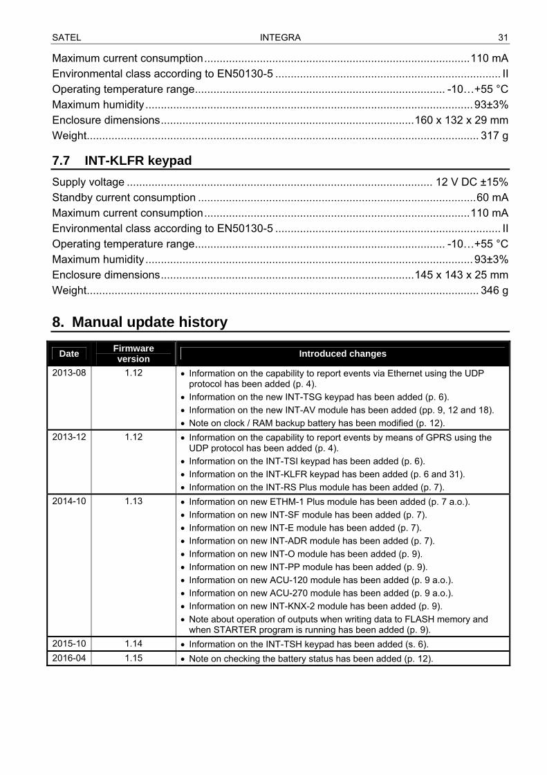
7.7 INT-KLFR keypad
Supply voltage ................................................................................................... 12 V DC ±15%
Standby current consumption ..........................................................................................60 mA
Maximum current consumption......................................................................................110 mA
Environmental class according to EN50130-5 ......................................................................... II
Operating temperature range................................................................................. -10…+55 °C
Maximum humidity .......................................................................................................... 93±3%
Enclosure dimensions..................................................................................145 x 143 x 25 mm
Weight............................................................................................................................... 346 g
8. Manual update history
Date Firmware version
Introduced changes
2013-08 1.12 Information on the capability to report events via Ethernet using the UDP protocol has been added (p. 4).
Information on the new INT-TSG keypad has been added (p. 6).
Information on the new INT-AV module has been added (pp. 9, 12 and 18).
Note on clock / RAM backup battery has been modified (p. 12).
2013-12 1.12 Information on the capability to report events by means of GPRS using the UDP protocol has been added (p. 4).
Information on the INT-TSI keypad has been added (p. 6).
Information on the INT-KLFR keypad has been added (p. 6 and 31).
Information on the INT-RS Plus module has been added (p. 7).
2014-10 1.13 Information on new ETHM-1 Plus module has been added (p. 7 a.o.).
Information on new INT-SF module has been added (p. 7).
Information on new INT-E module has been added (p. 7).
Information on new INT-ADR module has been added (p. 7).
Information on new INT-O module has been added (p. 9).
Information on new INT-PP module has been added (p. 9).
Information on new ACU-120 module has been added (p. 9 a.o.).
Information on new ACU-270 module has been added (p. 9 a.o.).
Information on new INT-KNX-2 module has been added (p. 9).
Note about operation of outputs when writing data to FLASH memory and when STARTER program is running has been added (p. 9).
2015-10 1.14 Information on the INT-TSH keypad has been added (s. 6).
2016-04 1.15 Note on checking the battery status has been added (p. 12).