
Installation, Use and Maintenance ManualIII Warnings Installation, Use and Maintenance Manual –...
52
Installation, Use and Maintenance Manual GAHP-GS/WS powered by gas and renewable energies water/water gas absorption heat pump
Transcript of Installation, Use and Maintenance ManualIII Warnings Installation, Use and Maintenance Manual –...
Installation, Use and Maintenance Manual
GAHP-GS/WS
powered by gas and renewable energies
water/water gas absorption heat pump

Revision: TCode: D-LBR509
This manual has been drawn up and printed by Robur S.p.A.; whole or partial reproduction of this manual is prohibited.The original is filed at Robur S.p.A.Any use of this manual other than for personal consultation must be previously authorised by Robur S.p.A.The rights of those who have legitimately filed the registered trademarks contained within this publication are not affected.With the aim of continuously improving the quality of its products, Robur S.p.A. reserves the right to modify the data and contents of this manual without prior notice.

Installation, Use and Maintenance Manual – GAHP-GS/WS 3
INDEX OF CONTENTS
I INTRODUCTION �����������������������������������������������4 II SYMBOLS AND DEFINITIONS �������������������������4
II.1 Key to symbols ......................................................................4 II.2 Terms and definitions .........................................................4
III WARNINGS �������������������������������������������������������4 III.1 General and safety warnings ...........................................4 III.2 Conformity .............................................................................6 III.3 Exclusions of liability and warranty ...............................6
1 FEATURES AND TECHNICAL DATA ����������������6 1.1 Features ...................................................................................6 1.2 Dimensions ............................................................................7 1.3 Components ..........................................................................9 1.4 Electrical wiring diagram ............................................... 12 1.5 Electronic boards .............................................................. 12 1.6 Operation mode ................................................................ 15 1.7 Controls ................................................................................ 15 1.8 Technical characteristics ................................................. 15
2 TRANSPORT AND POSITIONING �����������������17 2.1 Warnings .............................................................................. 17 2.2 Handling ............................................................................... 17 2.3 Appliance position (outdoor version) ....................... 18 2.4 Installation premises (indoor variant)........................ 18 2.5 Minimum clearance distances...................................... 18 2.6 Mounting base ................................................................... 19
3 HEATING ENGINEER ��������������������������������������19 3.1 Warnings .............................................................................. 19 3.2 Installation ........................................................................... 19 3.3 Hydraulic connections .................................................... 20 3.4 Water circulation pumps ................................................ 21 3.5 Anti-icing function............................................................ 21 3.6 Anti-icing liquid ................................................................. 21 3.7 System water quality ....................................................... 22
3.8 Installation filling .............................................................. 22 3.9 Fuel gas supply .................................................................. 22 3.10 Combustion products exhaust .................................... 23 3.11 Flue gas condensate discharge .................................... 28 3.12 Safety valve exhaust (indoor version) ........................ 29
4 ELECTRICAL INSTALLER �������������������������������29 4.1 Warnings .............................................................................. 29 4.2 Electrical systems .............................................................. 30 4.3 Electrical power supply ................................................... 31 4.4 Set-up and control ............................................................ 32 4.5 Water circulation pumps ................................................ 34
5 FIRST START-UP ��������������������������������������������37 5.1 Preliminary checks ............................................................ 37
6 NORMAL OPERATION �����������������������������������38 6.1 Warnings .............................................................................. 38 6.2 Switch on and off .............................................................. 38 6.3 Messages on the display ................................................ 38 6.4 Electronic adjustment on the machine – Menus
and parameters of the S61 board ............................... 39 6.5 Modifying settings ............................................................ 40 6.6 Restarting a locked-out unit - Reset ........................... 40 6.7 Efficiency .............................................................................. 41
7 MAINTENANCE ����������������������������������������������41 7.1 Warnings .............................................................................. 41 7.2 Pre-emptive maintenance ............................................. 41 7.3 Scheduled routine maintenance ................................. 41 7.4 Periods of inactivity .......................................................... 42
8 DIAGNOSTICS ������������������������������������������������42 8.1 Operative codes................................................................. 42
APPENDICES ��������������������������������������������������������45 1 Declaration of Conformity ............................................. 45 2 Product fiche....................................................................... 46

I Introduction
4
I INTRODUCTION
ManualThis Manual is an integral part of the GAHP-GS and GAHP-WS units and must be handed to the end user to-gether with the appliance.
RecipientsThis Manual is intended for:
▶ end user, for appropriate and safe use of the appliance;
▶ qualified installer, for correct appliance installation;
▶ planner, for specific information on the appliance.
Control deviceIn order to be able to work, the GAHP-GS/WS unit needs a con-trol device (DDC, CCP/CCI or external request), which must be connected by the installer.
II SYMBOLS AND DEFINITIONS
II�1 KEY TO SYMBOLS
DANGER
WARNING
NOTE
PROCEDURE
REFERENCE (to other document)
II�2 TERMS AND DEFINITIONSGAHP Appliance/Unit = equivalent terms, both used to des-ignate the gas powered absorption heat pump GAHP (Gas Ab-sorption Heat Pump).TAC = Technical Assistance Centre authorised by Robur.
External request =generic control device (e.g. thermostat, tim-er or any other system) equipped with a voltage-free NO contact and used as control to start/stop the GAHP unit.CCI Controller (Comfort Controller Interface) = optional Robur control device which lets you manage up to three modulating heat only GAHP units (A, WS, GS).CCP Controller(Comfort Control Panel) = Robur control device which lets you manage in modulation mode up to three GAHP units and all system components (probes, diverter/mixing valves, circulating pumps), including any integration boiler.DDC Control (Direct Digital Controller) = optional Robur device to control one or more Robur appliances (GAHP heat pumps, GA chillers and AY boilers) in ON/OFF mode.RB100/RB200 Devices (Robur Box) = optional interface devices complementary to DDC, which may be used to broaden its func-tions (heating/cooling/DHW production service demands, and control of system components such as third party generators, adjustment valves, circulating pumps, probes).Heat generator = equipment (e.g. boiler, heat pump, etc..) pro-ducing heating and/or DHW.GUE (Gas Utilization Efficiency) = efficiency index of gas heat pumps, equal to the ratio between the thermal energy pro-duced and the energy of the fuel used (relative to LCV, lower calorific value).First Switch-On = appliance commissioning operation which may only and exclusively be carried out by a TAC.S61/Mod10/W10 Boards = electronic boards on the GAHP unit, to control all functions and to provide interface with other devic-es and with the user.
III WARNINGS
III�1 GENERAL AND SAFETY WARNINGS
Installer's qualificationsInstallation must exclusively be performed by a Quali-fied Firm and by Skilled Personnel, with specific knowl-edge on heating, cooling, electrical systems and gas appliances, in compliance with the laws in force in the Country of installation.
Declaration of ConformityUpon completing installation, the installing firm shall issue to the owner/client the appliance's Workmanlike Conformity Declaration, according to national/local
regulations in force and the manufacturer's instructions/provisions.
MisuseThe appliance must only be used for the purposes for which it has been designed. Any other use is deemed hazardous. Incorrect use may affect operation, duration and safety of the appliance. Adhere to the manufactur-er's instructions.
Hazardous situations▶ Do not start the appliance in hazardous conditions,
such as: gas smell, problems with the plumbing/elec-trical/gas system, parts of the appliance under water

III Warnings
Installation, Use and Maintenance Manual – GAHP-GS/WS 5
or damaged, malfunctioning, disabling or bypassing control and safety devices.
▶ In case of danger, request intervention by skilled personnel.
▶ In case of danger, switch off the electrical power and gas supplies only if this can be done in total safety.
▶ Do not entrust children, persons with physical, senso-ry or mental disabilities or persons with poor knowl-edge and experience with use of the appliance.
Gas component tightness▶ Before performing any operation on gas ducting
components, close the gas cock.
▶ Upon completing any procedure, perform the tight-ness test according to regulations in force.
Gas smellIf you smell gas:
▶ Do not use electrical devices such as telephones, multimeters or other equipment that may cause sparks next to the appliance.
▶ Shut off the gas supply by turning the cock off.
▶ Disconnect electrical power supply by means of the external isolation switch in the power supply electri-cal panel.
▶ Use a telephone away from the appliance to ask for intervention from skilled personnel.
Poisoning▶ Ensure the flue gas ducts are tightness and compli-
ant with the regulations in force.
▶ Upon completing any procedure, ensure compo-nents are tightness.
Moving partsThe appliance contains moving parts.
▶ Do not remove guards during operation, and in any case prior to disconnecting the power supply.
Burn hazardThe appliance contains very hot parts.
▶ Do not open the appliance and do not touch internal components before the appliance has cooled down.
▶ Do not touch the flue gas exhaust before it has cooled down.
Pressure vesselsThe appliance has a sealed circuit classified as pres-sure vessel, the tightness of which is tested by the manufacturer.
▶ Do not carry out any intervention on the sealed cir-cuit or on the appliance's valves.
Water-ammonia solutionThe GAHP unit uses the ammonia-water absorption cycle. The water-ammonia solution is contained in the
sealed circuit. The solution is harmful for health if it is ingested, or comes in contact with the skin.
▶ In the event of coolant leak keep away and discon-nect the power and gas supply (only if it is possible to do so with no danger).
▶ Request assistance from the TAC.
Electrocution hazard▶ Disconnect the electrical power supply before any
work/procedure on appliance components..
▶ For electrical connections exclusively use compliant components and according to the specifications pro-vided by the manufacturer.
▶ Ensure the appliance cannot be accidentally switched back on.
EarthingElectrical safety depends on effective earthing system, correctly connected to the appliance and installed ac-cording to the regulations in force.
Distance from combustible or flammable materials▶ Do not store flammable materials (paper, solvents,
paint, etc.) in the vicinity of the appliance.
Limescale and corrosionDepending on the chemical/physical properties of the system water, limescale or corrosion may damage the appliance (Paragraph 3.7 p. 22).
▶ Check system tightness.
▶ Avoid frequent top-ups.
Chloride concentrationThe concentration of chlorides or free chlorine in the system water must not exceed the values in Table 3.2 p. 22.
Aggressive substances in airHalogenated hydrocarbons containing chlorine and flu-orine compounds cause corrosion. The supply air of the appliance must be free from aggressive substances.
Acid flue gas condensate▶ Discharge the acid condensate of combustion flue
gas, as indicated in Paragraph 3.11 p. 28, in com-pliance with current exhaust regulations.
Switching the appliance offDisconnecting the power supply while the appliance is running may cause permanent damage to internal components.
▶ Except in the case of danger, do not disconnect the power supply to switch off the appliance, but always and exclusively act through the control device pro-vided (DDC, CCP/CCI or external request).

1 Features and technical data
6
In the event of failureOperations on internal components and repairs may exclusively be carried out by a TAC, only using original parts.
▶ In the event of failure of the appliance and/or break-age of any component, do not attempt to repair and/or restore and immediately contact the TAC.
Routine maintenanceProper maintenance assures the efficiency and good operation of the appliance over time.
▶ Maintenance must be performed according to the manufacturer's instructions (see Chapter 7 p. 41) and in compliance with current regulations.
▶ Appliance maintenance and repairs may only be entrusted to firms legally authorised to work on gas appliances and systems.
▶ Enter into a maintenance contract with an author-ised specialised firm for routine maintenance and for servicing in case of need.
▶ Only use original parts.
Decommissioning and disposalIf the appliance is to be disposed of, contact the manu-facturer for its disposal.
Keep the ManualThis "Installation, Use and Maintenance Manual" must always accompany the appliance and must be hand-ed to the new owner or installer in the event of sale or removal.
III�2 CONFORMITY
EU Directives and standardsThe absorption heat pumps of the GAHP series are certified as conforming to standard EN 12309-1 and -2 and comply with the essential requirements of the following Directives:
▶ 2009/142/EC "Gas Appliances Directive" as amended and added.
▶ 2004/108/EC "Electromagnetic Compatibility Directive" as amended and added.
▶ 2006/95/EC "Low Voltage Directive" as amended and added.
▶ 2006/42/EC "Machine Directive" as amended and added.
▶ 97/23/EEC "Pressure Equipment Directive" as amended and added.
Furthermore, they comply with the requirements of the follow-ing standards:
▶ UNI EN 677 Specific requirements for condensing boilers with nominal heating capacity up to 70 kW.
▶ EN 378 Refrigerating systems and heat pumps.
Other applicable provisions and standardsThe design, installation, operation and maintenance of the sys-tems shall be carried out in compliance with current applicable regulations, depending on the Country and location, and in ac-cordance with the manufacturer's instructions. In particular, reg-ulations regarding the following shall be complied with:
▶ Gas systems and equipment.
▶ Electrical systems and equipment.
▶ Heating and air conditioning systems, and heat pumps.
▶ Environmental protection and combustion products ex-haust.
▶ Fire safety and prevention.
▶ Any other applicable law, standard and regulation.
III�3 EXCLUSIONS OF LIABILITY AND WARRANTY
Any contractual or extra-contractual liability of the manufacturer for any damage caused by incorrect in-stallation and/or improper use and/or failure to comply with regulations and with the manufacturer's direc-tions/instructions shall be disclaimed.
In particular, the warranty on the appliance may be ren-dered void by the following conditions:
▶ Incorrect installation.
▶ Misuse.
▶ Failure to comply with the manufacturer's indica-tions on installation, use and maintenance.
▶ Alteration or modification of the product or any part thereof.
▶ Extreme operational conditions or however out-side of the operational ranges set forth by the manufacturer.
▶ Damages caused by external agents such as salts, chlorine, sulphur or other chemical substances con-tained in the installation water or present in the air of the installation site.
▶ Abnormal actions transmitted by the plant or instal-lation to the appliance (mechanical stresses, pres-sure, vibrations, thermal dilations, power surges...).
▶ Accidental damages or due to force majeure.
1 FEATURES AND TECHNICAL DATA
1�1 FEATURES
OperationBased on the thermodynamic water-ammonia absorption cy-cle (H20–NH3), the appliance simultaneously produces hot wa-ter and chilled water, using the ground or well/ground/surface
water as a renewable energy source and natural gas (or LPG) as primary energy.The thermodynamic cycle takes place within a hermetically sealed circuit, in welded construction, perfectly tight, facto-ry-tested, which does not require any maintenance or refriger-ant top-ups.
1 Features and technical data
Installation, Use and Maintenance Manual – GAHP-GS/WS 7
Mechanical and thermo-hydraulic components ▶ steel sealed circuit, externally treated with epoxy paint;
▶ Sealed combustion chamber (type C);
▶ metal mesh radiant burner equipped with ignition and flame detection device, controlled by an electronic control unit;
▶ titanium stainless steel shell-and-tube water exchanger (condenser), externally insulated;
▶ titanium stainless steel shell-and-tube water exchanger (evaporator), externally insulated;
▶ stainless steel, shell and tube recovery exchanger of flue gas latent heat.
Control and safety devices ▶ S61 electronic board with microprocessor, LCD display and
knob;
▶ Mod10 additional electronic board (integrated in S61);
▶ auxiliary W10 electronic board
▶ installation water flow meter (hot side);
▶ installation water flow switch (cold side);
▶ generator limit thermostat, with manual reset;
▶ flue gas temperature thermostat, with manual reset;
▶ generator fin temperature sensor;
▶ sealed circuit safety relief valve;
▶ by-pass valve, between high and low pressure circuits;
▶ ionisation flame controller;
▶ gas solenoid valve with double shutter;
▶ condensate discharge obstruction sensor.
Indoor or outdoor versionsThe GS and WS units are available in two variants, indoor or out-door, according to the installation site.
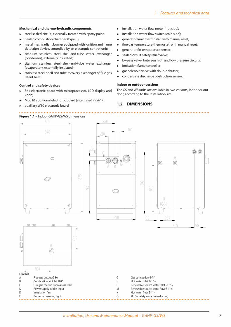
1�2 DIMENSIONS
Figure 1�1 – Indoor GAHP-GS/WS dimensions
LEGENDA Flue gas output Ø 80B Combustion air inlet Ø 80C Flue gas thermostat manual resetD Power supply cables inputE Ventilation fanF Burner on warning light
G Gas connection Ø ¾"H Hot water inlet Ø 1"¼L Renewable source water inlet Ø 1"¼M Renewable source water flow Ø 1"¼N Hot water flow Ø 1"¼Q Ø 1"¼ safety valve drain ducting

1 Features and technical data
8
Figure 1�2 – Outdoor GAHP-GS/WS dimensional drawing
LEGENDA Flue gas output Ø 80B Combustion air inlet Ø 80C Flue gas thermostat manual resetD Power supply cables inputE Ventilation fanF Appliance operation warning lightG Gas connection Ø ¾"H Hot water inlet Ø 1"¼L Renewable source water inlet Ø 1"¼M Renewable source water flow Ø 1"¼N Hot water flow Ø 1"¼P Condensate drain

1 Features and technical data
Installation, Use and Maintenance Manual – GAHP-GS/WS 9
1�3 COMPONENTS
Figure 1�3 – Internal components - front view
LEGEND1. Ventola di aerazione2. Gas valve3. Blower4. Tmix Probe5. Electrical panel6. Oil pump7. Flow meter (hot side)

1 Features and technical data
10
Figure 1�4 – Internal components - left side view
1
3
4
2
5
6
7
8
9
10
LEGEND1. Manual air vent (cold side)2. Flow switch (cold side))3. Flue gas thermostat reset4. Ø 80mm flue gas exhaust5. Flue gas thermostat sensor6. PT 1000 Flue gas Temperature Probe7. Condensate drain senso8. Ignitor and flame detector9. Condensate drain siphon10. Manual air vent valve (hot side)

1 Features and technical data
Installation, Use and Maintenance Manual – GAHP-GS/WS 11
Figure 1�5 – Internal components - right side view
LEGEND1. Safety valve2.TG Probe3. Limit thermostat4. Ignition transformer5. Flow temperature probe (hot side)

1 Features and technical data
12
1�4 ELECTRICAL WIRING DIAGRAM
Figure 1�6 – Appliance wiring diagram
LEGENDSCH1 S61 Electronic boardSCH2 W10 Electronic boardSCH3 Mod10 Electronic boardTER Appliance power supply terminal blockCNTBOX Flame controllerPWRTR Board transformerBLW BlowerPMP Oil pumpIGNTR Ignition transformerIGN Ignition electrodesFLS Flame sensor
LS Gas valve ON warning lightGV Gas solenoid valveTHMF Cold water flow temperature probeTHRF Cold water inlet temperature probeTMIX Combustion air temperature probeTA Ambient air temperature probeTG Generator temperature probeTHMC Hot water flow temperature probeTHRC Hot water inlet temperature probeREED Oil pump rotation sensor
TF Flue gas temperature probe or genera-tor fins probe
TC Manual flue gas thermostatTL Generator limit thermostatFM Hot side flow meterFL Renewable source water flow switchCWS Condensation water sensorMA Connecting terminal boardTK Condensate drain resistor thermostatFS Condensate drain resistor
1�5 ELECTRONIC BOARDS
Electronic boards (S61+Mod10)The unit's electrical board contains:
▶ Electronic Board S61 (Figure 1.7 p. 13), with micropro-cessor, it controls the appliance and displays data, messages and operative codes. The appliance is monitored and pro-grammed by interacting with the display and knob.
▶ Auxiliary Mod10 Electronic Board (Figure 1.8 p. 14), overlapping S61, controls power modulation of the burner and water circulation pump rate variation.
▶ Satellite W10 Electronic Board (Figure 1.9 p. 14), in-terconnected to the S61 board and located next to it, used mainly to control hot side circulating pump.

1 Features and technical data
Installation, Use and Maintenance Manual – GAHP-GS/WS 13
Figure 1�7 – Electronic board S61
LEGENDSCH1 S61 Electronic boardSCH3 Mod10 Electronic board (for more
details see specific figure)A1, A2 Auxiliary inputsENC KnobF1 Fuse T 2AF2 Fuse F 10AF3 Fuse T 2AF4 Fuse T 3.15AFAN (BK, WH, BR) Cooling fan outputFL Flow switch inputFS5 (24V AC) Board power supply 24-0-
24 VacIGN.BOX (L, N) Flame controller power
supply 230 VacJ1 Jumper CAN BUS
J10 Jumper N.O. contactJ82 Board connector W10 (on Mod10)JP10 6 pole flame controller connectorJP12 Flue gas probe or generator fin probe
inputJTAG Connector for board programming S61MAIN 230V (L,N) S61 Board power supply
230 VacN.O. CONTACT Normally open pump
contactP7 (R, W, Y, O) Request inputP8 (GND, L, H) CAN BUS ConnectorPUMP 230V (L,N) Oil pump power supply
outputSPI Mod10 Board communication portSRT1 Oil pump rotation sensor input
SRT2 Hot water flow meter inputTA Ambient air temperature probe inputTA1 Hot water flow temperature probe
inputTA2 Hot water inlet temperature probe
inputTCN Combustion air temperature probe
inputTF Flue gas thermostat inputTG Generator temperature probe inputTHMF Cold water inlet temperature probe
inputTHRF Cold water inlet temperature probe
inputTL Generator limit thermostat input

1 Features and technical data
14
Figure 1�8 – Mod10 controller
Mod10 controller
Figure 1�9 – W10 electronic controller
LEGENDHFLOW Not usedCFLOW Condensation water sensor controlJ51 SPI connectorHPMP Primary circuit hot water pump control
output (0-10 V) [A/GS/WS]CPMP Cold side water pump control output
[GS/WS]NC1-C1 Status indication of locking warnig/errorCN5 Blower controlJ82 W10 auxiliary controller connectorJ83 W10 cable shielding connection W10CN1 Inputs 0-10V (not used)
LEGENDJP1 Communication with S61/Mod10

1 Features and technical data
Installation, Use and Maintenance Manual – GAHP-GS/WS 15
1�6 OPERATION MODE
ON/OFF or modulating operationThe GAHP unit may work in two modes:
▶ mode (1) ON/OFF, i.e. On (at full power) or Off, with circulat-ing pumps at constant flow;
▶ mode (2) MODULATING, i.e. at variable load from 50% to 100% of power, with circulating pumps at variable flow (hot side) and constant flow (cold side).
For each mode, (1) o (2), specific control systems and devices are provided (Paragraph 1.5 p. 12).
1�7 CONTROLS
Control deviceThe appliance may only work if it is connected to a control de-vice, selected from:
▶ (1) DDC control ▶ (2) CCP/CCI control ▶ (3) external request
1�7�1 Adjustment system (1) with DDC (GAHP unit ON/OFF)The DDC controller is able to control appliances, a single GAHP unit, or even several GAHP/GA/AY units in cascade, only in ON/OFF mode(non modulating).For more details refer to the DDC, RB100, RB200 Manuals and the Design Manual.
DDC ControllerThe main functions are:
▶ setup and control of one (or more) Robur units of the ab-sorption line (GAHP, GA, AY);
▶ parameter figures display and setting;
▶ hourly programming;
▶ climate curve control;
▶ diagnostics;
▶ reset errors;
▶ possibility to interface with a BMS;
DDC functionality may be extended with auxiliary Robur devices RB100 and RB200 (e.g. service requests, DHW production, Third Party generator control, probe control, system valves or circulat-ing pumps, ...).
1�7�2 Adjustment system (2) with CCP/CCI (modulating GAHP unit)The CCP/CCI control is able to control in heating only (and pos-sibly passive cooling) up to 3 GAHP units in modulating mode (therefore A/WS/GS only, excluding AR/ACF/AY), plus any inte-gration ON/OFF boiler. For additional details and diagrams refer to the CCP/CCI Manual and the Planning Manual.
CCP/CCI ControlSee CCP/CCI device Booklet.
1�7�3 Control system (3) with external request (GAHP unit ON/OFF)The appliance may also be controlled via generic request de-vices (e.g. thermostat, timer, button, contactor...) fitted with voltage-free NO contact. This system only provides elementary control (on/off, with fixed set-point temperature), hence without the important functions of systems (1) and (2). It is advisable to possibly limit its use to simple applications only and with a sin-gle appliance.There are two control options: heating request or cooling request.
For connection of the selected device to the appliance's electronic board please refer to Paragraph 4.4 p. 32.
1�8 TECHNICAL CHARACTERISTICS(see Table 1.1 p. 15).
Table 1�1 – GS-HT, WS Technical data
GAHP GS HT GAHP WSHEATING MODESeasonal space heating energy efficien-cy class (ErP)
medium-temperature application (55 °C) A++low-temperature application (35 °C) A+
OPERATING POINT B0W50* (Brine inlet 0°C, hot Water outlet +50°C)
G.U.E. gas usage efficiency % 149 (1) --Thermal power delivered kW 37,6 (1) --Power recovered from renewable source kW 12,1 --
OPERATING POINT B0W35* (Brine inlet 0°C, hot Water outlet +35°C)
G.U.E. gas usage efficiency % 165 (1) --Thermal power delivered kW 41,6 (1) --Power recovered from renewable source kW --
OPERATING POINT B0W65* (Brine inlet 0°C, hot Water outlet +65°C)
G.U.E. gas usage efficiency % 125 (1) --Thermal power delivered kW 31,5 (1) --Power recovered from renewable source kW 7.0 --
OPERATING POINT W10W50G.U.E. gas usage efficiency % -- 165 (1)Thermal power delivered kW -- 41,6 (1)Power recovered from renewable source kW -- 16,6
OPERATING POINT W10W65G.U.E. gas usage efficiency % -- 143 (1)Thermal power delivered kW -- 35,8 (1)Power recovered from renewable source kW -- 11,5
Heating capacityNominal (1013 mbar - 15°C) kW 25,7true peak kW 25,2

1 Features and technical data
16
GAHP GS HT GAHP WS
Hot water delivery temperaturemaximum for heating °C 65maximum for DHW °C 70
Hot water inlet temperature
maximum heating °C 55maximum for DHW °C 60minimum temperature in continuous operation °C 20 (10)
Thermal differential nominal °C 10
Hot water flow ratenominal l/h 3170 3570maximum l/h 4000minimum l/h 1400
Hot water pressure lossfor nominal water flow (B0W50) bar 0,49 (2)for nominal water flow rate(W10W50) bar 0,57 (2)
Ambient air temperature (dry bulb)maximum °C 45minimum °C 0
RENEWABLE SOURCE OPERATING CONDITIONSRenewable source water return temperature maximum °C 45
Renewable source delivery water temperature minimum °C -5 3
Renewable source water flow rate (with 25% glycol)
nominal (B0W50) l/h 3020 --maximum l/h 4000 --minimum l/h 2000 --
Renewable source water flow ratenominal (W10W50) l/h -- 2850maximum l/h -- 4700minimum l/h -- 2300
Renewable source pressure drop at nominal flow rate bar 0,51 (2) 0,38 (2)ELECTRICAL SPECIFICATIONS
Power supplyVoltage V 230TYPE SINGLE PHASEFrequency 50 Hz supply 50
Electrical power absorption nominal kW 0,41 (5)Degree of protection IP X5DINSTALLATION DATA
gas consumption
methane G20 (nominal) m3/h 2,72 (3)methane G20 (min) m3/h 1,34G25 (nominal) m3/h 3,16G25 (min) m3/h 1,57G30 (nominal) kg/h 2,03 (4)G30 (min) kg/h 0,99G31 (nominal) kg/h 2,00 (4)G31 (min) kg/h 0,98
NOx emission class 5NOx emission ppm 25CO emission ppm 36Sound power Lw (max) dB(A) 66,1 (7)Sound pressure Lp at 5 metres (max) dB(A) 44,1 (8)Minimum storage temperature °C -30Maximum water pressure in operation bar 4Maximum flow flue condensate l/h 4,0
Water content inside the apparatusHOT SIDE l 4COLD SIDE l 3
Water fittingTYPE Fthread " G 1 1/4
Gas connectionTYPE Fthread " G 3/4
Safety valve outlet channel fitting " G 1"1/4 (9)
Fume outletDiameter (∅) mm 80Residual head Pa 80Product configuration C63
Dimensionswidth mm 848 (6)depth mm 690height mm 1278
Weight In operation kg 300GENERAL INFORMATIONINSTALLATION MODE C13, C33, C43, C53, C63, C83, B23P, B33
REFRIGERANT FLUIDAMMONIA R717 kg 7 7,7WATER H2O kg 10

2 Transport and positioning
Installation, Use and Maintenance Manual – GAHP-GS/WS 17
GAHP GS HT GAHP WS
MAXIMUM PRESSURE OF THE REFRIGERANT CIRCUIT bar 32
Note:
(1) As per standard EN12309-2(2)For flows other than nominal see Planning Manua(3) PCI (G20) 34,02 MJ/m3 (1013 mbar 15 °C).(4) PCI (G30/G31) 46.34 MJ/kg (1013 mbar 15 °C).(5) ± 10% according to the power supply voltage and tolerance on electrical motors consumption.(6) Overall dimensions without flue gas exhaust ducts.(7) Sound power values detected in compliance with the intensity measurement methodology set forth by standard EN ISO 9614; C13 type installation.(8) Maximum sound pressure levels in free field, with directionality factor 2, obtained from the sound power level in compliance with standard EN ISO 9614; C13 type installation.(9) Indoor version only. (10) In transient operation, lower temperatures are allowed.
Table 1�2 – PED data
GAHP GS HT GAHP WSPED data
COMPONENTS UNDER PRESSURE
Generator l 18,6Leveling chamber l 11,5Evaporator l 3,7Cooling volume transformer l 4,5Absorber/condenser l 3,7Cooling absorber solution l 6,3Solution pump l 3,3
TEST PRESSURE (IN AIR) bar g 55MAXIMUM PRESSURE OF THE REFRIGERANT CIRCUIT bar g 32FILLING RATIO kg of NH3/l 0,136 0,149FLUID GROUP GROUP 1°
2 TRANSPORT AND POSITIONING
2�1 WARNINGS
Damage from transport or installationThe manufacturer shall not be liable for any damage during appliance transport and installation.
On-site inspection▶ Upon arrival at the site, ensure there is no transport
damage on packing, metal panels.
▶ After removing the packing materials, ensure the ap-pliance is intact and complete.
Packing▶ Only remove the packing after placing the appliance
on site.
▶ Do not leave parts of the packing within the reach of children (plastic, polystyrene, nails...) since they are potentially dangerous.
Weight▶ The crane and lifting equipment must be suitable for
the load.
▶ Do not stand under suspended loads.
2�2 HANDLING
Handling and lifting ▶ Always handle the appliance in its packing, as delivered by
the factory.
▶ To lift the appliance use straps or slings inserted in the holes of the base (Figure 2.1 p. 18).
▶ Use hanging and spacing rods to avoid damaging the outer panels (Figure 2.1 p. 18).
▶ Comply with safety regulations at the installation site.

2 Transport and positioning
18
Figure 2�1 – Lift GS/WS
In the event of handling with forklift or pallet truck, comply with the handling instructions shown on the packing.
2�3 APPLIANCE POSITION (OUTDOOR VERSION)
Do not install the outdoor version inside a room, not even if it has openings. In no event the outdoor version may be started inside a room.
Where to install the applianceIn the outdoor version the appliance:
▶ May be only installed outside buildings, out of the dripping line of rain gutters or the like. It does not require protection from weathering.
▶ The appliance may be installed at ground level, on a terrace or on a roof, compatibly with its dimensions and weight.
▶ The appliance's flue gas exhaust must not be immediately close to openings or air intakes of buildings, and must com-ply with environmental regulations.
▶ Do not install near the exhaust of flues, chimneys or hot polluted air. In order to work correctly, the appliance needs clean air.
Acoustic issues ▶ Pre-emptively assess the appliance's sound effect in connec-
tion to the site, taking into account that building corners, en-closed courtyards, restricted spaces may amplify the acous-tic impact due to the reverberation phenomenon.
2�4 INSTALLATION PREMISES (INDOOR VARIANT)The installation premises must meet all the requirements set forth by laws, standards and regulations of the Country and place of installation regarding gas appliances and cooling appliances
Do not install in a room that has no aeration openings.
Features of the installation premises ▶ The premises must be provided with permanent and suffi-
ciently wide ventilation openings to permit even air flow for aeration and possibly for combustion (if type B installation).
▶ Combustion air intake may be ducted from the outside (type C installation).
▶ The flue gas exhaust must be ducted to the outside. The flue opening must not be immediately close to openings or air intakes of buildings, and must comply with environmental regulations.
2�5 MINIMUM CLEARANCE DISTANCESFor both the indoor and outdoor version:
Distances from combustible or flammable materials ▶ Keep the appliance away from combustible or flammable
materials or components, in compliance with applicable regulations.
Clearances around the applianceThe minimum clearance distances shown in Figure 2.2 p. 19 (bar any stricter regulations) are required for safety, operation and maintenance.

3 Heating engineer
Installation, Use and Maintenance Manual – GAHP-GS/WS 19
Figure 2�2 – Clearances
2�6 MOUNTING BASE
Base or floor construction features ▶ Place the appliance on a levelled flat surface made of fire-
proof material and able to withstand its weight.
For the outdoor version:
(1) - installation at ground level ▶ Failing a horizontal supporting base, make a flat and lev-
elled concrete base, at least 100-150 mm larger than the ap-pliance size per side.
(2) - installation on terrace or roof ▶ The structure of the building must support the total weight
of the appliance and the supporting base.
▶ If necessary, provide a maintenance walkway around the appliance.
Anti vibration mountingsAlthough the appliance's vibrations are minimal, resonance phenomena might occur in roof or terrace installations.
▶ Use anti-vibration mountings.
▶ Also provide anti-vibration connections between the appli-ance and water and gas pipes.
3 HEATING ENGINEER
3�1 WARNINGS
General warningsRead the warnings in Chapter III p. 4, providing im-portant information on regulations and on safety.
Compliance with installation standardsInstallation must comply with applicable regulations in force, based on the installation Country and site, in mat-ters of safety, design, implementation and maintenance of:
▶ heating systems;
▶ cooling systems;
▶ gas systems;
▶ flue gas exhaust;
▶ flue gas condensate discharge.
Installation must also comply with the manufacturer's provisions.
3�2 INSTALLATION
Primary and secondary circuit ▶ In many cases it is advisable to divide the water installation
(hot side) into two parts, primary and secondary circuit, un-coupled by a hydraulic separator, or possibly by a tank that also acts as inertial volume/thermal inertia.
Constant ot variable water flowThe GAHP unit is able to operate with constant water flow rate (always on the cold side) or variable (on hot side only), according to ON/OFF or modulating operative mode.System and components must be designed and installed consistently.
Minimum water contentHigh thermal inertia is conducive to efficient appliance opera-tion. Very short ON/OFF cycles are to be avoided.
3 Heating engineer
20
▶ If necessary, provide for an inertial volume (on hot side), to be suitably sized (see planning manual).
Heating and/or coolingIt may be required to alternatively or simultaneously produce hot water and/or chilled water. The selection of the type of op-eration may be performed by the control device, by suitably se-lecting the priority (cooling or heating).
3�3 HYDRAULIC CONNECTIONS
Plumbing fittingson the rear panel (Figure 1.1 p. 7 1.2 p. 8).
▶ N (= out) 1"1/4 F -WATER OUTPUT (hot) (m = flow to the in-stallation);
▶ H (= in) 1"1/4 F- WATER INPUT (hot) (r = inlet from the in-stallation).
▶ M (= out) 1"1/4 F - WATER OUTPUT (cold) (m = flow to the installation);
▶ L (= in) 1"1/4 F - WATER INPUT (cold) (r = inlet from the in-stallation).
Hydraulic pipes, materials and features ▶ Use pipes for heating/cooling installations, protected from
weathering, insulated for thermal losses, with vapour barrier to prevent condensation.
Pipe washing ▶ Before connecting the appliance, accurately clean
the water and gas piping and any other system com-ponent, removing any residue.
Minimum components of primary water circuits Always provide, near the applianceo,both on the hot side and cold side:on water piping, both output and input (m/r)
▶ 2 ANTIVIBRATION JOINTS on water fittings;
▶ 2 PRESSURE GAUGES;
▶ 2 ISOLATION BALL VALVES;
on the input water piping (r) ▶ 1 DIRT SEPARATOR FILTER
▶ 1 FLOW ADJUSTMENT VALVE, if the circulating pump is con-stant flow;
▶ 1 WATER CIRCULATION PUMP, towards the appliance;
on the output water piping (m) (hot side only) ▶ 1 SAFETY VALVE (3 bar);
▶ 1 EXPANSION TANK of the individual unit.
For GAHP-WS with open circuit the EXCHANGER is obligatory.
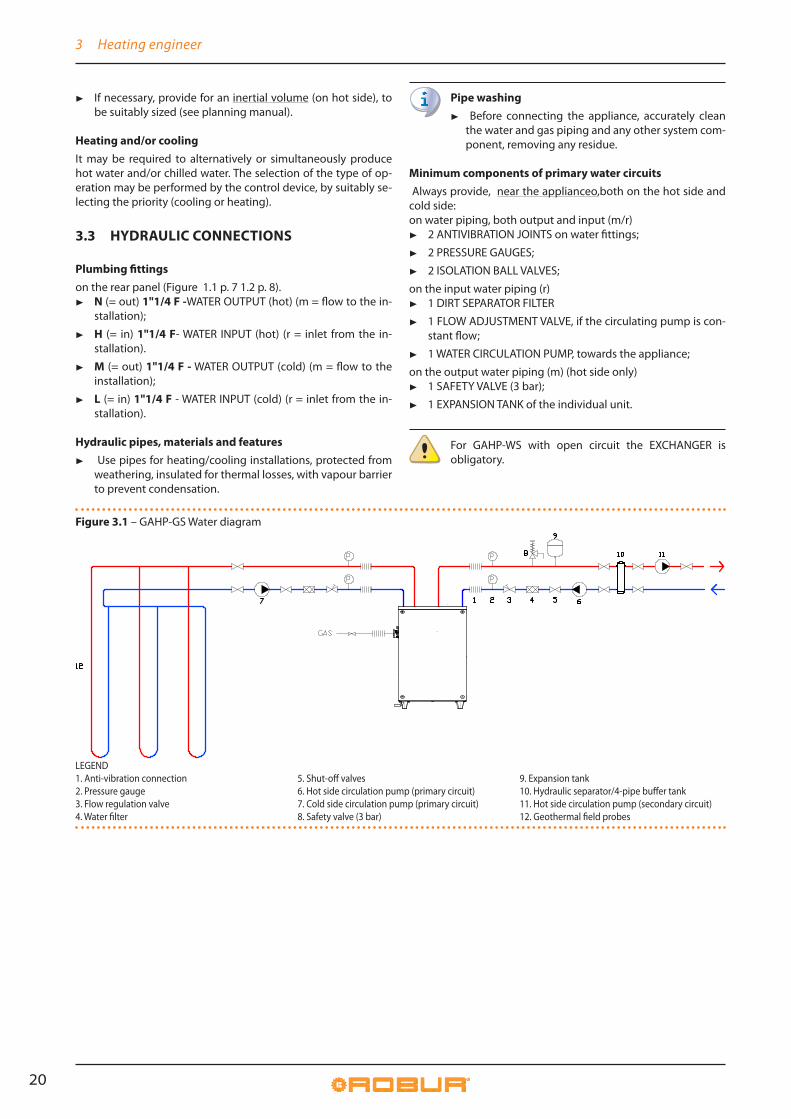
Figure 3�1 – GAHP-GS Water diagram
LEGEND1. Anti-vibration connection2. Pressure gauge3. Flow regulation valve4. Water filter
5. Shut-off valves6. Hot side circulation pump (primary circuit)7. Cold side circulation pump (primary circuit)8. Safety valve (3 bar)
9. Expansion tank10. Hydraulic separator/4-pipe buffer tank11. Hot side circulation pump (secondary circuit)12. Geothermal field probes

3 Heating engineer
Installation, Use and Maintenance Manual – GAHP-GS/WS 21
Figure 3�2 – GAHP-WS Water diagram
LEGEND1. Anti-vibration connection2. Pressure gauge3. Flow regulation valve4. Water filter5. Shut-off valves
6. Hot side circulation pump (primary circuit)7. Cold side circulation pump (primary circuit)8. Safety valve (3 bar)9. Expansion tank10. Hydraulic separator/4-pipe buffer tank
11. Hot side circulation pump (secondary circuit)12. Heat exchanger13. Pumping sump14. Drain sump15. Submersible pump
3�4 WATER CIRCULATION PUMPSThe appliance needs two water circulation pumps, one for the hot side and one for the cold side.The circulation pumps (flow and head) must be selected and in-stalled based on pressure losses of water/primary circuit (piping + components + exchange terminals + appliance).For the appliance's pressure losses refer to Table 1.1 p. 15 and Design Manual.
(1) CONSTANT FLOW circulating pumpsThe circulating pumps, primary on hot side and cold side, must obligatorily be controlled by the appliance's electronic board (S61) (see Paragraph 1.5 p. 12).
(2) VARIABLE FLOW circulating pumpFor variable flow,operation, hot side only (the cold side always runs on constant flow), it is obligatory to use Wilo Stratos Pa-ra pumps,supplied as accessory on demand, which must be connected to the electronic board Mod10 (see Paragraph 1.5 p. 12). Any other type of pump will give constant flow.Refer to the Design Manual for the features of the Wilo Stratos Para pump.
3�5 ANTI-ICING FUNCTION
Active anti-icing self-protection (hot side only)The appliance is equipped with an active anti-icing self-protec-tion system to prevent icing. The anti-icing function (activated by default) automatically starts primary circulation pumps and, if required, the burner too, when the outside temperature ap-proaches zero.
Electrical and gas continuityThe active anti-icing self-protection is only effective if the power and gas supplies are assured. Otherwise, an-ti-icing liquid might be required.
3�6 ANTI-ICING LIQUID
Precautions with glycolThe manufacturer disclaims any liability for any damage caused by improper glycol use.
▶ Always check product suitability and its expiry date with the glycol supplier. Periodically check the prod-uct's preservation state.
▶ Do not use car-grade anti-icing liquid (without inhib-itors), nor zinc-coated piping and fittings (incompat-ible with glycol).
▶ Glycol modifies the physical properties of water (density, viscosity, specific heat...). Size the piping, cir-culation pump and thermal generators accordingly.
▶ With automatic system water filling, a periodic check of the glycol content is required.
With high glycol percentage (> 20…30%)If the glycol percentage is ≥30% (for ethylene glycol) or ≥20% (for propylene glycol) the TAC must be alerted be-fore first start-up.
Hot side and cold side glycolAssess the need to add glycol on the hot side. On the cold side, glycol is recommended (in general) or indispensable (with chilled water operating temperatures lower than zero).
Type of anti-icing glycolInhibited type glycol is recommended to prevent oxidation phenomena.
Glycol effectsThe Table 3.1 p. 22 shows, indicatively, the effects of using a glycol depending on its %.

3 Heating engineer
22
Table 3�1 – Technical data for filling the hydraulic circuit
GLYCOL % 10 15 20 25 30 35 40WATER-GLYCOL MIXTURE FREEZING TEMPERATURE -3°C -5°C -8°C -12°C -15°C -20°C -25°CPERCENTAGE OF INCREASE IN PRESSURE DROPS -- 6% 8% 10% 12% 14% 16%LOSS OF EFFICIENCY OF UNIT -- 0,5% 1% 2% 2,5% 3% 4%
3�7 SYSTEM WATER QUALITY
Responsibility of the user/operator/installerThe installer, operator and user must assure system wa-ter quality (Table 3.2 p. 22). Failure to comply with the manufacturer's guidelines may affect operation, integri-ty and life of the appliance, voiding the warranty.
Table 3�2 – Chemical and physical parameters of water
CHEMICAL AND PHYSICAL PARAMETERS OF WATER IN HEATING/COOLING SYSTEMS
PARAMETER UNIT OF MEASUREMENT ALLOWABLE RANGE
pH \ >7 (1)
Chlorides mg/l < 125 (2)
Total hardness (CaCO3)°f < 15°d < 8.4
Iron mg/kg < 0.5 (3)
Copper mg/kg < 0.1 (3)
Aluminium mg/l < 1Langelier’s index \ 0-0,4HARMFUL SUBSTANCESFree chlorine mg/l < 0.2 (3)
Fluorides mg/l < 1Sulphides ABSENT
1 with aluminium or light alloys radiators, pH must also be lower than 8 (in compliance with applicable rules) 2 value referred to the maximum water temperature of 80 °C 3 in compliance with applicable rules
System water featuresFree chlorine or water hardness may damage the appliance.Adhere to the chemical-physical parameters in Table 3.2 p. 22 and the regulations on water treatment for residential and in-dustrial heating systems.
Water topping upThe chemical-physical properties of the system's water may alter over time, resulting in poor operation or excessive topping up.
▶ Ensure there are no leaks in the installation.
▶ Periodically check the chemical-physical parameters of the water, particularly in case of automatic topping up.
Chemical conditioning and washingWater treatment/conditioning or system washing car-ried out carelessly may result in risks for the appliance, the system, the environment and health.
▶ Contact specialised forms or professionals for water treatment or system washing.
▶ Check compatibility of treatment or washing prod-ucts with operating conditions.
▶ Do not use aggressive substances for stainless steel or copper.
▶ Do not leave washing residues.
3�8 INSTALLATION FILLING
How to fill up the system
After completing all water, electrical and gas connections:
1. Pressurise (at least 1.5 bar) and vent the hydraulic circuit.
2. Let water flow (with appliance off).
3. Check and clean the filter on the inlet pipe.
4. Repeat items 1, 2 and 3. until the pressure has stabi-lised (at least 1.5 bar).
To vent the system do not use the appliance's vent, ex-clusively intended for the internal exchanger.
3�9 FUEL GAS SUPPLY
Gas connection ▶ 3/4" F
on the left side, at the top, side panel (Detail G Figures 1.1 p. 7 1.2 p. 8).
▶ Install an anti-vibration connection between the appliance and the gas piping.
Mandatory shut-off valve ▶ Provide a gas shut-off valve (manual) on the gas supply line,
to isolate the appliance when required.
▶ Perform connection in compliance with applicable regula-tions.
Gas pipes sizingThe gas pipes must not cause excessive load losses and, conse-quently, insufficient gas pressure for the appliance.
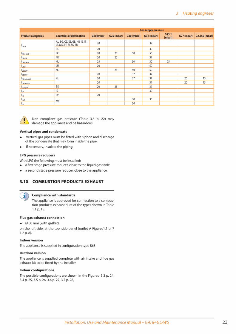
Supply gas pressureThe appliance's gas supply pressure, both static and dynamic, must comply with Table 3.3 p. 22, with tolerance ± 15%.
Table 3�3 – Network gas pressure
Gas supply pressure
Product categories Countries of destination G20 [mbar] G25 [mbar] G30 [mbar] G31 [mbar] G25�1 [mbar] G27 [mbar] G2,350 [mbar]
II2H3B/P
AL, BG, CY, CZ, DK, EE, FI, GR, HR, IT, LT, MK, NO, RO, SE, SI, SK, TR
20 30 30
AT, CH 20 50 50
3 Heating engineer
Installation, Use and Maintenance Manual – GAHP-GS/WS 23
Gas supply pressure
Product categories Countries of destination G20 [mbar] G25 [mbar] G30 [mbar] G31 [mbar] G25�1 [mbar] G27 [mbar] G2,350 [mbar]
II2H3P
AL, BG, CZ, ES, GB, HR, IE, IT, LT, MK, PT, SI, SK, TR 20 37
RO 20 30II2ELL3B/P DE 20 20 50 50II2Esi3P FR 20 25 37II2HS3B/P HU 25 30 30 25II2E3P LU 20 50II2L3B/P NL 25 50 50II2E3B/P
PL20 37 37
II2ELwLs3B/P 20 37 37 20 13II2ELwLs3P 20 37 20 13I2E(S); I3P BE 20 25 37I3P IS 30I2H LV 20I3B/P MT
30 30I3B 30
Non compliant gas pressure (Table 3.3 p. 22) may damage the appliance and be hazardous.
Vertical pipes and condensate ▶ Vertical gas pipes must be fitted with siphon and discharge
of the condensate that may form inside the pipe.
▶ If necessary, insulate the piping.
LPG pressure reducersWith LPG the following must be installed:
▶ a first stage pressure reducer, close to the liquid gas tank;
▶ a second stage pressure reducer, close to the appliance.
3�10 COMBUSTION PRODUCTS EXHAUST
Compliance with standardsThe appliance is approved for connection to a combus-tion products exhaust duct of the types shown in Table 1.1 p. 15.
Flue gas exhaust connection ▶ Ø 80 mm (with gasket),
on the left side, at the top, side panel (outlet A Figures1.1 p. 7 1.2 p. 8).
Indoor versionThe appliance is supplied in configuration type B63
Outdoor versionThe appliance is supplied complete with air intake and flue gas exhaust kit to be fitted by the installer
Indoor configurationsThe possible configurations are shown in the Figures 3.3 p. 24, 3.4 p. 25, 3.5 p. 26, 3.6 p. 27, 3.7 p. 28,

3 Heating engineer
24
Figure 3�3 – Type C13 coaxial flue gas exhaust
LEGEND80/125A Splitter DN80/125 2xDN80B Wall coaxial terminal DN80/125E Coaxial pipe 80/125 L= 1 m (o 2 m)F Coaxial elbow 90° (or 45°) 80/12560/100A Splitter DN60/100 2xDN80B Wall coaxial terminal DN60/100E Coaxial pipe 60/100 L= 1 m (o 2 m)F Coaxial elbow 90° (or 45°) 60/100

3 Heating engineer
Installation, Use and Maintenance Manual – GAHP-GS/WS 25
Figure 3�4 – Type C33 coaxial flue gas exhaust
LEGEND80/125A Splitter DN80/125 2xDN80B Roof coaxial terminal 80/125C Pitched roof tile terminal
D Flat roof tile terminalE Roof coaxial pipe 80/125 L= 1 m (or 2 m)F Coaxial elbow 90° (or 45°) 80/125
60/100A Splitter DN60/100 2xDN80B Roof coaxial terminal 60/100C Pitched roof tile terminalD Flat roof tile terminalE Roof coaxial pipe 60/100 L= 1 m (or 2 m)F Coaxial elbow 90° (or 45°) 60/100
3 Heating engineer
26
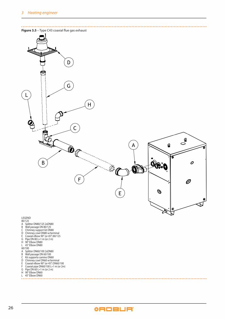
Figure 3�5 – Type C43 coaxial flue gas exhaust
LEGEND80/125A Splitter DN80/125 2xDN80B Wall passage DN 80/125C Chimney support kit DN80D Chimney cowl DN80 w/terminalE Coaxial elbow 90° (or 45°) 80/125G Pipe DN 80 L=1 m (or 2 m)H 90° Elbow DN80L 45° Elbow DN8060/100A Splitter DN60/100 2xDN80B Wall passage DN 60/100C Kit supporto camino DN60D Chimney cowl DN60 w/terminalE Coaxial elbow 90° (or 45°) DN60/100F Coaxial pipe DN60/100 L=1 m (or 2m)G Pipe DN 60 L=1 m (or 2 m)H 90° Elbow DN60L 45° Elbow DN60

3 Heating engineer
Installation, Use and Maintenance Manual – GAHP-GS/WS 27
Figure 3�6 – Type C53 roof flue gas exhaust
LEGEND80A B C Split exhaust intake kit DN80D Chimney cowl DN80 w/terminalE Chimney support kit DN80F Pipe DN80 L = 1 m (or 2 m)G 90° Elbow DN80H 45° Elbow DN80

3 Heating engineer
28
Figure 3�7 – Type C53 split wall flue gas exhaust
LEGEND80B C D Wall terminal kit DN80F Pipe DN80 L=1 m (or 2 m)G 90° Elbow DN80H 45° Elbow DN80
Any flueIf necessary, the appliance may be connected to a flue.
▶ To size the flue refer to Table 3.4 p. 28 and Design Manual.
▶ If several appliances are connected to a single flue, it is oblig-atory to install a check valve on the exhaust of each.
▶ The flue must be designed, sized, tested and constructed by a skilled form, with materials and components complying with the regulations in force in the country of installation.
▶ Always provide a socket for flue gas analysis, in an accessible position.
Table 3�4 – Fumes temperature and flow
Gas type Heating capacity CO2 (%) TF (C°) Fumes flow (kg/h) Residual head (Pa)
G20Nominal 9,10 65 42 80
Minimum 8,90 46 21 80
G25Nominal 9,10 63,6 42 80
Minimum 8,90 45,7 21 80
G25.1Nominal 10,10 65 45 80
Minimum 9,60 46 23 80
G27Nominal 9,0 64 42 80
Minimum 8,5 46 21 80
G2.350Nominal 9,00 62,7 42 80
Minimum 8,70 46,8 22 80
G30Nominal 10,40 65 43 80
Minimum 10,10 46 22 80
G31Nominal 9,10 65 48 80
Minimum 8,90 46 24 80
3�11 FLUE GAS CONDENSATE DISCHARGEThe GAHP-A unit is a condensing appliance and therefore pro-duces condensation water from combustion flue gases.
Condensate acidity and exhaust regulationsThe flue gas condensate contains aggressive acid sub-stances. Refer to applicable regulations in force for con-densate exhaust and disposal.
▶ If required, install an acidity neutraliser of adequate capacity.

4 Electrical installer
Installation, Use and Maintenance Manual – GAHP-GS/WS 29
Do not use gutters to discharge the condensate Do not discharge the fume condensate water in gutters, due to the risk of materials corrosion and ice formation.
Flue gas condensate connectionThe fitting for flue gas condensate discharge is located on the left side of the appliance (Figure 3.8 p. 29).
▶ The distance L between the sleeve and the base must not exceed 110 mm.
▶ The corrugated condensate discharge pipe must be con-nected to a suitable discharge manifold.
▶ The junction between the pipe and the manifold must re-main visible.
Flue gas condensate discharge manifoldTo make the condensate discharge manifold:
▶ Size the ducts for maximum condensation capacity (Table 1.1 p. 15).
▶ Use plastic materials resistant to acidity pH 3-5.
▶ Provide for min. 1% slope, i.e. 1 cm for each m of the length (otherwise a booster pump is required).
▶ Prevent freezing.
▶ Dilute, if possible, with domestic waste water (e.g. bath-rooms, washing machines, dish washers...), basic and neu-tralising.
Figure 3�8 – Flue gas condensate drain manifold
LEGENDA Condensate drain capD Corrugated hose
3�12 SAFETY VALVE EXHAUST (INDOOR VERSION)
The safety valve drain must be obligatorily ducted out-side. Failure to comply with this provision jeopardises first switch on.
Do not install any shut off device on the exhaust duct between the safety valve and the outside exhaust.
Safety valve drain ductingThe exhaust ducting, made in steel pipes (do not use copper or its alloys) must have the features set out in the Table 3.5 p. 29
Table 3�5 – Safety valve drain ducting
Diameter DN Maximum length (m)1" 1/4 32 302" 50 60
How to make the safety valve drain ducting1. Remove the plastic cap on the appliance's top panel
(Detail Q Figure 1.1 p. 7)
2. Connect the exhaust duct, which must have an initial straight section of at least 30 cm, to outlet Q;
3. Fasten the pipe to the nut on the safety valve outlet, taking care to place the Teflon seal supplied with the appliance in between;
4. Place the drain terminal outside the room, away from doors, windows and aeration vents, and at such a height that any coolant leaks cannot be inhaled by any people.
4 ELECTRICAL INSTALLER
4�1 WARNINGS
General warnings
Read the warnings in Chapter III p. 4, providing im-portant information on regulations and on safety.
Compliance with installation standards

4 Electrical installer
30
Installation must comply with applicable regulations in force, based on the installation Country and site, in mat-ters of safety, design, implementation and maintenance of electrical systems.
Installation must also comply with the manufacturer's provisions.
Live components▶ After placing the appliance in the final position, and
prior to making electrical connections, ensure not to work on live components.
Earthing▶ After placing the appliance in the final position, and
prior to making electrical connections, ensure not to work on live components.
▶ It is forbidden to use gas pipes as earthing.
Cable segregationKeep power cables physically separate from signal ones.
Do not use the power supply switch to turn the ap-pliance on/off�▶ Never use the external isolation switch (GS) to turn
the appliance on and off, since it may be damaged in the long run (occasional black outs are tolerated).
▶ To turn the appliance on and off, exclusively use the suitably provided control device (DDC, CCP/CCI or external request).
Control of water circulation pumpsThe two water circulation pumps of the hydraulic/pri-mary circuit, hot side and cold side, must mandatorily be controlled by the appliance's electronic boards (S61 + Mod10). It is not admissible to start/stop the circulat-ing pump with no request from the appliance.
4�2 ELECTRICAL SYSTEMSElectrical connections must provide:
▶ (a) power supply (Paragraph 4.3 p. 31);
▶ (b) control system (Paragraph 1.5 p. 12).
How to perform connectionsAll electrical connections must be made in the appli-ance's Electrical Board (Figure 4.1 p. 31):
1. Ensure the appliance's Electrical Panel is not live.
2. Remove the front panel of the appliance and the cover of the Electrical Board.
3. Insert the cables through the suitable holes in the rear panel, at the bottom left (Detail D Figure 1.1 p. 7, 1.2 p. 8).
4. Run the cables through the suitable cable glands in the Electrical Board.
5. Identify the appropriate connection terminals.
6. Perform the connections.
7. Close the Electrical Panel.and fit the front panel back on.
4 Electrical installer
Installation, Use and Maintenance Manual – GAHP-GS/WS 31
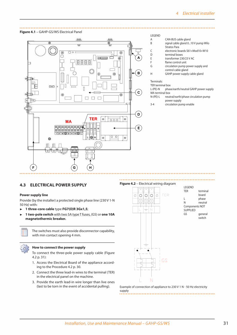
Figure 4�1 – GAHP-GS/WS Electrical Panel
4�3 ELECTRICAL POWER SUPPLY
Power supply lineProvide (by the installer) a protected single phase line (230 V 1-N 50 Hz) with:
▶ 1 three-core cable type FG7(O)R 3Gx1,5;
▶ 1 two-pole switch with two 5A type T fuses, (GS) or one 10A magnetothermic breaker�
The switches must also provide disconnector capability, with min contact opening 4 mm.
How to connect the power supplyTo connect the three-pole power supply cable (Figure 4.2 p. 31):
1. Access the Electrical Board of the appliance accord-ing to the Procedure 4.2 p. 30.
2. Connect the three lead-in wires to the terminal (TER) in the electrical panel on the machine.
3. Provide the earth lead-in wire longer than live ones (last to be torn in the event of accidental pulling).
Figure 4�2 – Electrical wiring diagram
Example of connection of appliance to 230 V 1 N - 50 Hz electricity supply
LEGENDA CAN-BUS cable glandB signal cable gland 0...10 V pump Wilo
Stratos ParaC electronic boards S61+Mod10+W10D terminal boxesE transformer 230/23 V ACF flame control unitG circulation pump power supply and
control cable glandH GAHP power supply cable gland
Terminals:TER terminal boxL-(PE)-N phase/earth/neutral GAHP power supplyMA terminal boxN-(PE)-L neutral/earth/phase circulation pump
power supply3-4 circulation pump enable
LEGENDTER terminal
boardL phaseN neutralComponents NOT SUPPLIEDGS general
switch

4 Electrical installer
32
4�4 SET-UP AND CONTROL
Control systems, options (1) (2) (3)Three separate adjustment systems are provided, each with specific features, components and diagrams (see 4.4 p. 33, 4.5 p. 34):
▶ System (1), with DDC control (with CAN-BUS connection).
▶ System (2), with CCP/CCI control (with CAN-BUS connection).
▶ System (3), with an external request.
CAN-BUS communication networkThe CAN-BUS communication network, implemented with the cable of the same name, makes it possible to connect and re-motely control one or more Robur appliances with the DDC or CCP/CCI control devices.
It entails a certain number of serial nodes, distinguished in: ▶ intermediate nodes, in variable number;
▶ terminal nodes, always and only two (beginning and end);
Each component of the Robur system, appliance (GAHP, GA, AY, ...) or control device (DDC, RB100, RB200, CCI, ...), corresponds to a node, connected to two more elements (if it is an intermedi-ate node) or to just one other element (if it is a terminal node) through two/one CAN-BUS cable section/s, forming an open lin-ear communication network (never star or loop-shaped).
CAN-BUS signal cableThe DDC or CCP/CCI controllers are connected to the appliance through the CAN-BUS signal cable, shielded, compliant to Table 4.1 p. 32 (admissible types and maximum distances).
Table 4�1 – CAN BUS cables type
CABLE NAME SIGNAL / COLOR MAX LENGTH NoteRobur
Ordering Code OCVO008ROBUR NETBUS H= BLACK L= WHITE GND= BROWN 450 mHoneywell SDS 1620
In all cases the fourth conductor should not be used
BELDEN 3086AH= BLACK L= WHITE GND= BROWN 450 m
TURCK type 530DeviceNet Mid CableTURCK type 5711 H= BLUE L= WHITE GND= BLACK 450 mHoneywell SDS 2022TURCK type 531 H= BLACK L= WHITE GND= BROWN 200 m
For lengths ≤200 m and max 4 nodes (e.g. 1 DDC + 3 GAHP), a simple 3x0.75 mm shielded cable may even be used.
How to connect the CAN BUS cable to the applianceTo connect the CAN-BUS cable to the S61 electronic board (Paragraph 1.5 p. 12), located in the Electrical Panel inside the unit, (Figure 4.3 p. 32 and 4.4 p. 33):
1. Access the Electrical Board of the appliance accord-ing to the Procedure 4.2 p. 30);
2. Connect the CAN-BUS cable to terminals GND, L and H (shielding/earthing + two signal conductors);
3. Place the CLOSED J10 Jumpers (Detail A) if the node is terminal (one connected CAN-BUS cable section only), or OPEN (Detail B) if the node is intermediate (two connected CAN-BUS cable sections);
4. Connect the DDC or the CCP/CCI to the CAN-BUS cable according to the instructions in the following Paragraphs and the DDC or CCP/CCI Manuals.
Figure 4�3 – Electrical wiring diagram
LEGENDSCH electronic boardGND Common dataL Data signal LOWH Data signal HIGHJ1 Jumper CAN-BUS in boardA Detail case "terminal node" (3 wires; J1=jumper "closed")B Detail case "intermediate node" (6 wires; J1=jumper "open")P8 Port can/connector
Connection cable CAN BUS to electronic board: detail A case "terminal node", detail B case "intermediate node"
GAHP Configuration (S61) + DDC or CCP/CCI(Systems (1) and (2) Figure 4.4 p. 33,see also Paragraph 1.7 p. 15.

4 Electrical installer
Installation, Use and Maintenance Manual – GAHP-GS/WS 33
Figure 4�4 – Connexion câble CAN BUS for plants with one unit
LEGENDDDC direct digital controlSCH electronic board S61J1 Jumper CAN-BUS in board S61J21 Jumper CAN-BUS in board DDCA terminal nodes connection - (3 wires; J1 e J21 = "closed")H,L,GND data signal wires (rif. cables table)
External request(System (3) Figure 4.5 p. 34, 4.6 p. 34,see also Paragraph 1.7 p. 15.It is required to arrange:
▶ request device (e.g. thermostat, clock, button, ...) fitted with a voltage-free NO contact.
How to connect the external requestConnection of external request is effected on the S61 board located in the Electrical Panel inside the appli-ance (Figure 4.5 p. 34 4.6 p. 34):
1. Access the Electrical Board of the appliance accord-ing to the Procedure 4.2 p. 30.
2. connect the voltage-free contact of the external device through two lead wires to terminals R and W of electronic board S61, respectively common 24 V AC and heating request, if the unit works with heating priority, or to terminals R andY, respective-ly common 24 V AC and cooling request, if the unit works with cooling priority (Detail CS).
4 Electrical installer
34
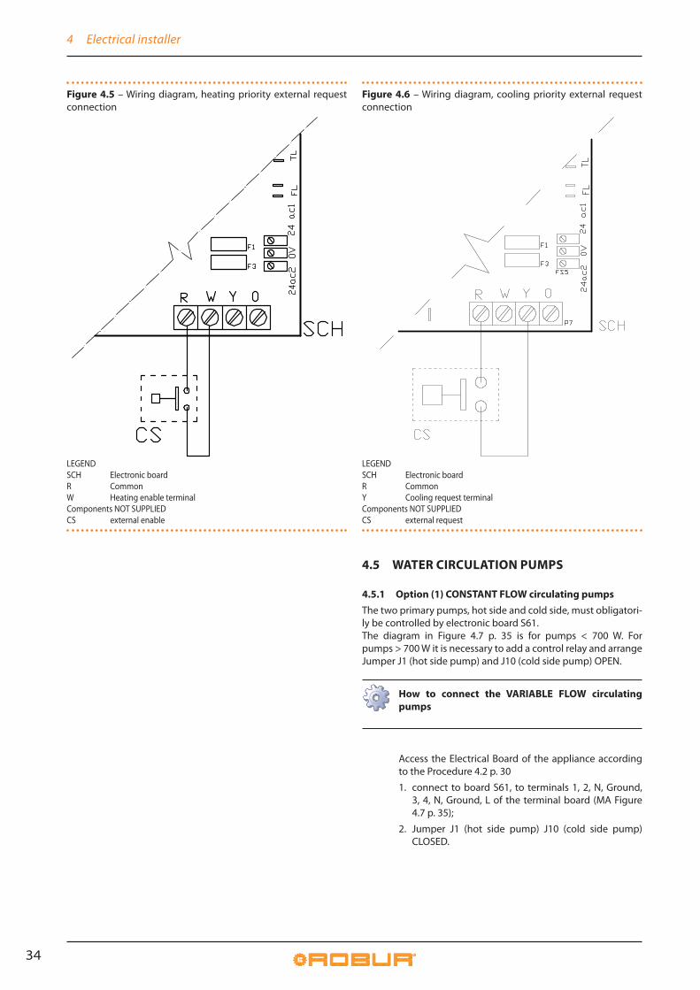
Figure 4�5 – Wiring diagram, heating priority external request connection
LEGENDSCH Electronic boardR CommonW Heating enable terminalComponents NOT SUPPLIEDCS external enable
Figure 4�6 – Wiring diagram, cooling priority external request connection
LEGENDSCH Electronic boardR CommonY Cooling request terminalComponents NOT SUPPLIEDCS external request
4�5 WATER CIRCULATION PUMPS
4�5�1 Option (1) CONSTANT FLOW circulating pumpsThe two primary pumps, hot side and cold side, must obligatori-ly be controlled by electronic board S61.The diagram in Figure 4.7 p. 35 is for pumps < 700 W. For pumps > 700 W it is necessary to add a control relay and arrange Jumper J1 (hot side pump) and J10 (cold side pump) OPEN.
How to connect the VARIABLE FLOW circulating pumps
Access the Electrical Board of the appliance according to the Procedure 4.2 p. 30
1. connect to board S61, to terminals 1, 2, N, Ground, 3, 4, N, Ground, L of the terminal board (MA Figure 4.7 p. 35);
2. Jumper J1 (hot side pump) J10 (cold side pump) CLOSED.

4 Electrical installer
Installation, Use and Maintenance Manual – GAHP-GS/WS 35
Figure 4�7 – Constant rate pumps connection wiring diagram
4�5�2 Option (2) VARIABLE FLOW circulating pumpsThe two primary pumps must obligatorily be controlled by elec-tronic board Mod10 (built into S61).
Only the hot side pump will actually be controlled with variable flow. The cold side pump will in any case be controlled with constant flow-
How to connect the VARIABLE FLOW circulating pumpsThe Wilo Stratos Para pump is already standard supplied with the power supply cable and signal cable, both 1.5m long.
For longer distances, use respectively cable FG7 3Gx-1.5mm² m and shielded cable 2x0.75 mm² suitable for 0-10V signal.
To connect the Wilo Stratos Para pumps (Figure 4.8 p. 36 J 45 or 4.9 p. 37 J 46)
1. Connect the brown wire of the hot side pump to terminal "-" HPMP and the white wire to terminal "+" HPMP of the Mod10 board.
2. Connect the brown wire of the cold side pump to terminal "-" CPMP and the white wire to terminal "+" CPMP of the Mod10 board.
3. Isolate the black wire and the blue one.
4. Protect the two pumps' supply line with a two-pole switch with 2 A delayed fuse (Detail IP, Figure 4.8 p. 36J 45), or connect it directly to the terminals inside the appliance's Electrical Board (Detail MA, Figure 4.9 p. 37 J 46).
LEGENDSCH electronic boardSCH2 electronic boardJ10 closed jumper (cold side pump)J1 closed jumper (hot side pump)N.O. CONTACT normally open voltage-free
contactsMA unit terminal boardL phaseN neutralComponents NOT SUPPLIEDPMW hot side water pump <700WPMY cold side water pump <700W

4 Electrical installer
36
Figure 4�8 – Wiring diagram for connection of Wilo Stratos Para variable rate pumps
LEGENDIP Two-position pump power switchF FusePMW Hot side water circulation pump (primary circuit)PMY Cold side water circulation pump
Pump signal 0-10V wire colours brown connect to -vewhite white connect to +ve black isolateblue isolate

5 First start-up
Installation, Use and Maintenance Manual – GAHP-GS/WS 37
Figure 4�9 – Wiring diagram for hooking up the Wilo Stratos Para variable rate pumps powered by the unit
5 FIRST START-UP
First Start-Up entails checking/setting up the combus-tion parameters and may exclusively be carried out by a Robur TAC. NEITHER the user NOR the installation tech-nician is authorised to perform such operations, under penalty of voiding the warranty.
5�1 PRELIMINARY CHECKS
Preliminary checks for First start-upUpon completing installation, before contacting the TAC the in-staller must check:
▶ correctly executed water-heating, electrical and gas sys-tems, suitable for the required capacities and equipped with all safety and control devices required by the regulations in force;
▶ absence of leaks in the water and gas systems;
▶ type of gas for which the appliance is designed (methane or LPG);
▶ supply gas pressure complying with the values of Table 3.3 p. 22, with max tolerance ±15%;
▶ Power supply mains complying with the appliance's rating plate data;
▶ correctly installed air/flue gas ducts;
▶ correctly installed flue gas condensate drain;
▶ appliance correctly installed, according to the manufactur-er's instructions;
▶ system installed in a workmanlike manner, according to na-tional and local regulations.
LEGENDPMW Hot side water circulation pump (primary
circuit)PMY Cold side water circulation pumpMA Unit terminal block
Pump signal 0-10V wire coloursbrown connect to -vewhite connect to +veblack isolateblue isolate

6 Normal operation
38
Abnormal or hazardous installation situationsShould any abnormal or hazardous installation situations be found, the TAC shall not perform First start-up and the appliance shall not be commissioned.These situations may be:
▶ appliance installed within premises without safety valve drain ducting;
▶ failed compliance with minimum clearances;
▶ insufficient distance from combustible or flammable mate-rials;
▶ conditions that do not warrant access and maintenance in safety;
▶ appliance switched on/off with the main switch, instead of the control device provided (DDC, CCP/CCI or external re-quest);
▶ appliance defects or faults caused during transport or instal-lation;
▶ gas smell;
▶ non-compliant mains gas pressure;
non-compliant flue gas exhaust; ▶ all situations that may involve operation abnormalities or are
potentially hazardous.
Non-compliant system and corrective actionsShould the TAC find any non conformities, the user/installer is bound to perform any corrective procedures required by the TAC.After performing the remedial actions (the installer's responsi-bility), if the TAC deems that safety and conformity conditions are in place, "First start-up" may be effected.
6 NORMAL OPERATIONThis section is for the end user.
6�1 WARNINGS
General warningsPrior to using the appliance carefully read the warnings in Chapter III p. 4, providing important information on regulations and on safety.
First start-up by TACFirst Switch-on must exclusively be carried out by a Ro-bur TAC (Chapter 5 p. 37).
Never power the appliance off while it is runningNEVER power the appliance off while it is running (ex-cept in the event of danger, Chapter III p. 4), since the appliance or system might be damaged.
6�2 SWITCH ON AND OFF
Routine switching on/offThe appliance may exclusively be switched on/off by means of the suitably provided control device (DDC, CCP/CCI or external requests).
Do not Switch On/Off with the power supply switchDo not switch the appliance on/off with the power sup-ply switch. This may be harmful and dangerous for the appliance and for the system.
Inspections before switching onBefore switching on the appliance, ensue that:
▶ gas cock open;
▶ appliance electrical power supply (main switch (GS) ON);
▶ DDC or CCP/CCI power supply (if present);
▶ water circuit ready.
How to switch on/off ▶ If the appliance is controlled by a DDC or by a CCP/CCI (sys-
tems (1) and (2) see Paragraph 1.7 p. 15), refer to the re-spective manuals.
▶ If the appliance is controlled by external request (e.g. ther-mostat, clock, button, ... with voltage-free NO contact), (sys-tem (3) see Paragraph 1.7 p. 15), the appliance is switched on/off by the ON/OFF positions of the external control de-vice.
After switching on with the control, in normal operating condi-tions, the appliance starts/stops automatically according to the user's thermal needs, supplying hot or cold water at the pro-grammed temperature.
Although the external request is in the "ON" position, this does not mean the appliance will start immediate-ly, but it will only start when there are actual service demands.
6�3 MESSAGES ON THE DISPLAY
4 digit displayThe S61 board of the appliance (Paragraph 1.5 p. 12, Figure 6.1 p. 39) is fitted with a 4-digit display, visible through the sight glass of the front panel.
▶ When the appliance is powered on, all the LEDs switch on for 3 sec, then the S61 board name is displayed.
▶ After another 15 sec, the appliance is ready to operate.
Signals in normal operation ▶ During normal operation, water temperature values alter-
nate on the display: output,input and the difference be-tween the two.
Signals in the event of faultIn the event of fault the display blinks indicating an operational code (first letter on the display: "E" = error, or "U" = warning)
▶ If it is only a temporary warning, the appliance may continue working.
▶ If it is a permanent error or warning the appliance stops
(Table 8.1 p. 42).
6 Normal operation
Installation, Use and Maintenance Manual – GAHP-GS/WS 39
6�4 ELECTRONIC ADJUSTMENT ON THE MACHINE – MENUS AND PARAMETERS OF THE S61 BOARD
Firmware
The instructions on the use of the S61 electronic board concern the firmware version 3�028.
The appliance's electronic board (S61)
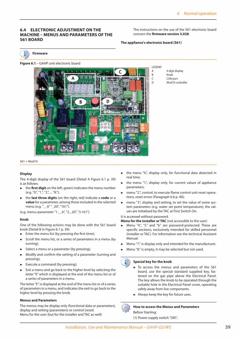
Figure 6�1 – GAHP unit electronic board
S61 + Mod10
DisplayThe 4-digit display of the S61 board (Detail A Figure 6.1 p. 39) is as follows:
▶ the first digit on the left, green) indicates the menu number (e.g. "0.", "1.", "2.", ... "8.");
▶ the last three digits (on the right, red) indicate a code or a value for a parameter, among those included in the selected menu (e.g. "__6" "_20", "161").
(e.g. menu+parameter "1.__6", "2._20", "3.161").
KnobOne of the following actions may be done with the S61 board knob (Detail B in Figure 6.1 p. 39):
▶ Enter the menu list (by pressing the first time);
▶ Scroll the menu list, or a series of parameters in a menu (by turning);
▶ Select a menu or a parameter (by pressing);
▶ Modify and confirm the setting of a parameter (turning and pressing);
▶ Execute a command (by pressing);
▶ Exit a menu and go back to the higher level by selecting the letter “E” which is displayed at the end of the menu list or of a series of parameters in a menu.
The letter "E" is displayed at the end of the menu list or of a series of parameters in a menu, and indicates the exit to go back to the higher level by pressing the knob.
Menus and ParametersThe menus may be display only (functional data or parameters), display and setting (parameters) or control (reset)Menu for the user (but for the installer and TAC as well)
▶ the menu "0.", display only, for functional data detected in real time;
▶ the menu "1.", display only, for current values of appliance parameters;
▶ menu "2.", control, to execute flame control unit reset opera-tions, reset errors (Paragraph 6.6 p. 40);
▶ menu "3.", display and setting, to set the value of some sys-tem parameters (e.g. water set point temperature); the val-ues are initialised by the TAC at First Switch-On.
It is accessed without password.Menu for the installer or TAC (not accessible to the user)
▶ Menu "4.", "5." and "6." are password-protected. These are specific sections, exclusively intended for skilled personnel (installer or TAC). For information see the technical Assistant Manual.
▶ Menu "7." is display only and intended for the manufacturer.
▶ Menu "8." is empty, it may be selected but not used.
Special key for the knob▶ To access the menus and parameters of the S61
board, use the special standard supplied key, fas-tened on the gas pipe above the Electrical Panel. The key allows the knob to be operated through the suitable hole in the Electrical Panel cover, operating safely away from live components.
▶ Always keep the key for future uses.
How to access the Menus and ParametersBefore Starting:
(1) Power supply switch "ON";
LEGENDA 4 digit displayB KnobC CAN portD Mod10 controller

6 Normal operation
40
(2) Display of the S61 board showing in sequence the detected water temperature data (if the appliance is in normal operation), or the flashing malfunction and fail-ure codes (if the appliance is in failure).
To access the menus and parameters of the S61 board, proceed as follows (see also Figure 6.1 p. 39):
1. Remove the front panel by removing the fixing screws.
2. Remove the cover of the electrical board to access the S61 board knob.
3. Act on the knob by means of the special key through the suitable hole.
4. Press the knob once to display the menus: the first menu is displayed, "0." (= menu 0).
5. Turn the knob clockwise to scroll down and display the other/subsequent menus; the menu numbers will be displayed in order, "1.", "2.", ... , "6." ... or "E" (= exit).
6. Select the menu of interest (e.g. display "2.___" = menu 2) by pressing the knob; the first parameter code will be displayed, in menu order (e.g. display "2._20" = parameter 20 in menu 2).
7. Turn the knob clockwise to scroll down the other pa-rameters in the menu; the codes will be displayed in order (e.g. display "2._20", "2._21", ... "2._25" = param-eters 20, 21, ... 25 in menu 2), or letter "E" (= exit) at the end of the list. "
8. Select the parameter of interest (e.g. with code 161 in menu 3) by pressing the knob; the figure previous-ly assigned to the parameter will be displayed, read only or to be set (e.g. the figure "45" for parameter 161 in menu 3 = water temperature set-point at 45 °C); if instead of a figure/setting it is a command, a flashing code is displayed (e.g. "reS1" for the flame block reset command).
9. Press the knob to reconfirm the figure; or rotate the knob to modify the figure, and press at the end to confirm or set the new figure; if however, it is a mat-ter of controlling an appliance operation, press the knob to execute it.
10. To exit a parameter menu or the menu list and go back to the higher level, turn the knob to display the letter "E" for exit, then press the knob again.
11. Place the cover back on the electrical panel opening and fit the appliance's front panel back on.
6�5 MODIFYING SETTINGS
Modify the settings through the DDC or CCP/CCIIf the appliance is connected to the DDC or to the CCP/CCI control, refer to the relevant manual to modify settings.
How to raise/lower the water temperature set-pointThe water temperature set-point establishes the delivery tem-perature to the system (water output from the appliance), or return from the system (water input in the appliance). The tem-perature is pre-set by the TAC upon First Switch-On.
If the appliance is not connected to a DDC or CCP/CCI control, to raise/lower the water temperature set-point with the S61 board, proceed as follows:
1. Access menu 3 under parameter 161 (= hot wa-ter temperature set-point) or 075 (cold water temperature set-point) by rotating and pressing the knob; "3.161" must be displayed (procedure Paragraph6.4 p. 39);
2. Display the parameter value by pressing the knob; the previously set value is displayed (from 10 to 65 °C for hot water); to reconfirm the pre-existing value press the knob again, otherwise go to point 3.
3. Turn the knob to modify the value, increasing or de-creasing it, and press it to set the new value;
4. Exit menu 3, and from the menu list, by selecting and pressing letter "E" twice, and go back to the normal display of detected temperature data.
Do not modify complex settingsSpecific technical and system knowledge is required for complex settings. Contact a TAC.
6�6 RESTARTING A LOCKED-OUT UNIT - RESET
Fault signals on the displayIn the event of locked-down appliance, an operational code flashes on the display (first green figure on the left, letter "U" = warning or "E" = error).
▶ To restart the appliance you must know and perform the procedure concerning the issue signalled and identified by the code (Paragraph 8.1 p. 42).
▶ Only act if you are familiar with the issue and with the pro-cedure (technical expertise and professional qualifications might be required).
▶ If you do not know the code, the problem, or the procedure, or you do not have sufficient skills, and in any case of doubt, contact the TAC.
Locked-down applianceAn external intervention (reset or repair) is required due to an appliance fault or problem with the system.
▶ A reset may be enough for a temporary and provisional anomaly.
▶ For a fault or breakdown, alert the maintenance technician or TAC.
ResetTo reset a fault (e.g. "E.212" due to an extant flame controller lockout), there are two possibilities:(1) If the appliance is connected to a DDC or to a CCP/CCI you may act through the control device, as described in the relevant manual.(2) You may act directly from the S61 board as described below (if the appliance is controlled with external request, this is the only option).
How to perform reset from the S61 boardTo perform the reset directly from the S61 board:
1. Access Menu 2 under Parameter "__0", to reset flame lockout (Error E212), or Parameter "__1" for any other generic reset, turning and pressing the knob;

7 Maintenance
Installation, Use and Maintenance Manual – GAHP-GS/WS 41
"2.__0"/"2.__1" must be displayed (procedure Para-graph 6.4 p. 39);
2. Press the knob to display the flashing reset request (e.g. "reS1" to reset flame block).
3. Press the knob again (the second time) to perform the reset; the reset request stops blinking, then "2.__X" is displayed again (e.g. "2.__0"). The reset op-eration has been performed.
4. Exit menu 2 and the menu list, by selecting and pressing letter "E" twice, and go back to the normal display of detected temperature data.
6�7 EFFICIENCYFor increased appliance efficiency:
▶ Set the maximum hot water temperature or the minimum cold water temperature at the actual installation require-ment;
▶ Reduce repeated switch-ons to the minimum (low loads);
▶ Program appliance activation for actual periods of use;
▶ Keep water and air filters on plumbing and ventilation sys-tems clean.
7 MAINTENANCE
7�1 WARNINGS
Correct maintenance prevents problems, assures effi-ciency and keeps running costs low.
Maintenance operations described herein may exclu-sively be performed by the TAC or skilled maintenance technician.
Any operation on internal components may exclusively be performed by the TAC.
Before performing any operation, switch off the appli-ance by means of the control device (DDC, CCP/CCI or external request) and wait for the end of the switching off cycle, then disconnect power and gas supply, by act-ing on the electrical disconnecter and gas cock.
The efficiency checks and every other "check and maintenance operation" (see Tables 7.1 p. 41 and 7.2 p. 42) must be performed with a frequency ac-cording to current regulations or, if more restrictive, ac-cording to the provisions set forth by the manufacturer, installer or TAC.
Responsibility for efficiency checks, to be carried out for the aims of restricting energy consumption, lies with the system manager.
Heavy-duty useIf the unit is subject to heavy duty use (for example in process plants or in other conditions of continuous operation), maintenance operations must be more frequent.
7�2 PRE-EMPTIVE MAINTENANCE ▶ For pre-emptive maintenance, comply with the recommen-
dations in Table 7.1 p. 41.
Table 7�1
GUIDELINES FOR THE PREVENTIVE MAINTENANCE OPERATIONSCheck of the unit GAHP-A GAHP-GS/WS AY ACF GAHP-ARVisually check of the general condition of the unit and of its air heat exchanger (1) √ √ √Check the correct operation of the device used for monitoring the water flow √ √ √ √ √Check the % value of CO2 √ √ √check gas pressure to the burners √ √Check that the condensate discharge is clean[If necessary, frequency of the maintenace operation must be increased] √ √ √
Replace the belts after 6 years or 12,000 hours of operation √ √ √ √Check/restore the pressure of the primary hydronic circuit √Check/restore the air pressure inside of the expansion vessel of the primary hydronic circuit √Check for every DDC or CCI DDC or CCICheck that the plant is able to achive the setpoint temperature √Download the hystorical events √
1 - It is suggested the cleaning of the air heat exchanger once every 4 years [the optimal frequency of this operation is in any case a consequence of the installation site].
7�3 SCHEDULED ROUTINE MAINTENANCE ▶ For scheduled routine maintenance, perform the operations
in Table 7.2 p. 42, at least once every 2 years.

8 Diagnostics
42
Table 7�2
SCHEDULED MAINTENANCE OPERATIONS TO BE PERFORMED AT LEAST ONE EVERY TWO YEARSCheck of the unit GAHP-A GAHP-GS/WS AY ACF GAHP-ARClean the combustion chamber √* √* √ √ √*Clean the burner √* √* √ √ √*Clean the electrodes of ignition and flame sensing √ √ √ √ √
Check that the condensate discharge is clean √ √ √
Replace the silicone gasket between the front plate and the exchanger √
*Only in case the analysis of combustion products is non-compliant
7�4 PERIODS OF INACTIVITY
Avoid emptying the installation
Emptying the system may cause damage due to corro-sion of the water pipes.
Deactivate the system in winter
Should you intend to stop the appliance in the winter season, ensure at least one of the following conditions:
1. anti-icing function active (Paragraph 3.5 p. 21);
2. sufficient anti-icing glycol (Paragraph 3.6 p. 21).
Prolonged periods of inactivity ▶ Should you foresee to leave the appliance inactive for a long
period of time, disconnect it from the electrical and gas mains. These operations must be performed by Qualified Personnel.
How to deactivate the appliance for long periods of time
1. Switch the appliance off (6.2 p. 38).
2. Only when the appliance is completely off, power it off with the main switch/disconnector switch (Detail GS in Figure 4.2 p. 31).
3. Close the gas valve
4. If necessary, add water with glycol (if the appliance is disconnected from the power and gas mains, the active anti-icing protection is missing, Paragraph 3.5 p. 21).
How to reactivate the appliance after long periods of inactivity
Before reactivating the appliance, the operator/mainte-nance technician of the system must first of all:
▶ Check whether any maintenance operations are re-quired (contact the TAC; see Paragraphs 7.2 p. 41 and 7.3 p. 41).
▶ Check content and quality of the water in the system, and if necessary top it up (Paragraphs 3.8 p. 22, 3.7 p. 22 and 3.6 p. 21 ).
▶ Ensure the flue gas exhaust duct is not obstructed, and that the condensate drain is clean.
After completing the above checks:
1. Open the gas cock and ensure there are no leaks; should gas smell be noticed, close the gas cock again, do not switch any electrical devices on and request intervention by Skilled Personnel.
2. Power on with the main power supply switch (GS, Figure 4.2 p. 31).
3. Switch on the appliance by means of the provided control device (DDC, CCP/CCI or external request, Paragraph 4.4 p. 32).
8 DIAGNOSTICS
8�1 OPERATIVE CODES
Table 8�1 – Operative Codes
CODE DESCRIPTION Warning (u) Error (E)
200 FAULT ON RESET CIRCUIT OF FLAME CONTROLLER NA
• Power cycle the appliance.
If the code persists, shows up again or in case of doubt, contact the TAC.
201 GENERATOR LIMIT THERMOSTAT TRIP Contact authorised Technical Assistance.202 FLUE GAS THERMOSTAT TRIP Contact authorised Technical Assistance.
203 COLD WATER ANTI-FREEZE THERMOSTAT TRIPPED
Reset is automatic when the triggering condi-tion ceases. NA
205 AMBIENT TEMPERATURE EXCEEDING OPERATIVE LIMITS NA Reset is automatic when the triggering condi-
tion ceases.
206 AMBIENT TEMPERATURE LOWER THAN OPERA-TIVE LIMITS
Warning non bloccante (codice informativo).
The code is reset automatically when the trigger-ing condition ceases.
NA
207 GENERATOR TEMPERATURE HIGH Reset is automatic when the triggering condi-tion ceases.
Reset may be performed from the DDC/CCI or from the S61 board (menu 2, parameter 1).If the code persists, shows up again or in case of doubt, contact the TAC.
208 FLAME CONTROL UNIT ERROR NA Contact authorised Technical Assistance.

8 Diagnostics
Installation, Use and Maintenance Manual – GAHP-GS/WS 43
CODE DESCRIPTION Warning (u) Error (E)
210 INSUFFICIENT COLD WATER FLOW Reset is automatic when the triggering condi-tion ceases.
• Check and clean water filters on the system.• Check for air in the system.• Check water flow pump.• Power cycle the appliance.
Reset may be performed from the DDC/CCI or from the S61 board (menu 2, parameter 1). If the code persists, shows up again or in case of doubt, contact the TAC.
211 INSUFFICIENT ROTATION OF OIL PUMP
Reset occurs automatically 20 minutes after the code is generated.
Reset may be performed from the DDC/CCI or from the S61 board (menu 2, parameter 1).If the code persists, shows up again or in case of doubt, contact the TAC.
212 FLAME CONTROLLER UNIT ARREST Reset is automatic up to 4 attempts (in about 5 minutes).
• Gas supply check.
Reset may be performed from the DDC/CCI or from the S61 board (menu 2, parameter 0). If the code persists or in case of doubt, contact the TAC.
216 COLD OUTLET WATER TEMPERATURE PROBE FAULT NA
Reset may be performed from the DDC/CCI or from the S61 board (menu 2, parameter 1).If the code persists, shows up again or in case of doubt, contact the TAC.
217 COLD INLET WATER TEMPERATUREPROBE FAULT NA
Reset may be performed from the DDC/CCI or from the S61 board (menu 2, parameter 1).If the code persists, shows up again or in case of doubt, contact the TAC.
220 FAULTY GENERATOR TEMPERATURE PROBE NAReset may be performed from the DDC/CCI or from the S61 board (menu 2, parameter 1).If the code persists, shows up again or in case of doubt, contact the TAC.
222 WATER /FLOWMETER SWITCH FAULT NA
Reset may be performed from the DDC/CCI or from the S61 board (menu 2, parameter 1).If the code persists, shows up again or in case of doubt, contact the TAC.
223 FAULTY AIR/GAS MIXTURE TEMPERATURE PROBE NAReset may be performed from the DDC/CCI or from the S61 board (menu 2, parameter 1).If the code persists, shows up again or in case of doubt, contact the TAC.
224 FLUE GAS TEMPERATURE PROBE FAULT
Reset is automatic when the triggering condi-tion ceases.
Reset may be performed from the DDC/CCI or from the S61 board (menu 2, parameter 1).If the code persists, shows up again or in case of doubt, contact the TAC.
225 CONDENSATE DISCHARGE CLOGGED NA
• Check and clean condensate discharge.
Reset may be performed from the DDC/CCI or from the S61 board (menu 2, parameter 1). If the code persists, shows up again or in case of doubt, contact the TAC.
226 GENERATOR FIN TEMPERATURE PROBE FAULT
Reset is automatic when the triggering condi-tion ceases.
Reset may be performed from the DDC/CCI or from the S61 board (menu 2, parameter 1).If the code persists, shows up again or in case of doubt, contact the TAC.
228GAS SOLENOID VALVE EXCITED DURING FLAME CONTROLLER LOCK OUT
NA• Power off the appliance.
Contact the TAC.
229 GAS SOLENOID VALVE WITHOUT ELECTRICAL POWER
Reset occurs automatically if the gas solenoid valve switches on again within 10 minutes (with central flame control unit on).
Reset may be performed from the DDC/CCI or from the S61 board (menu 2, parameter 1).If the code persists, shows up again or in case of doubt, contact the TAC.
230 GENERATOR FINS TEMPERATURE HIGH Reset is automatic when the triggering condi-tion ceases.
Reset may be performed from the DDC/CCI or from the S61 board (menu 2, parameter 1).If the code persists, shows up again or in case of doubt, contact the TAC.
231 HOT WATER TEMPERATURE EXCEEDING OPERA-TIVE LIMITS
• Check configuration of other heat generators on the system.
• Check water flow.• Check system thermal load.
Reset is automatic when the triggering condi-tion ceases.
NA
232 COLD WATER TEMPERATURE LOWER THAN OPERATIVE LIMITS
• Check configuration of other chillers on the system.
• Check water flow.• Check system's chilling load.
Reset is automatic when the triggering condi-tion ceases.
NA

8 Diagnostics
44
CODE DESCRIPTION Warning (u) Error (E)
233 COLD WATER TEMPERATURE LOWER THAN OPER-ATIVE LIMITS (HEAT ONLY UNIT)
• Check configuration of other chillers on the system.
• Check water flow.• Check system's chilling load.
Reset is automatic when the triggering condi-tion ceases.
NA
234 POSSIBLE SOURCE ANOMALY • Check water circulation on renewable source side NA
236 BLOWER FAULT Reset occurs automatically 20 minutes after the code is generated.
Reset may be performed from the DDC/CCI or from the S61 board (menu 2, parameter 1).If the code persists, shows up again or in case of doubt, contact the TAC.
246 HIGH HOT INLET WATER TEMPERATURE
• Check configuration of other heat generators on the system.
Reset is automatic and occurs if the generating condition ceases with circulating pump on or 20 minutes after the code is generated with circulating pump off.
NA
247 HOT INLET WATER TEMPERATURE LOWER THAN OPERATIVE LIMITS
Reset occurs automatically when the generating cause resolves or 430 seconds after the code is generated.
Reset occurs automatically when the condition that generated the code ceases. If the code shows up again or in case of doubt contact the TAC.
248 HIGH HOT WATER DIFFERENTIAL TEMPERATURE• Check water flow.
Reset occurs automatically 20 minutes after the code is generated.
Reset occurs automatically when the condition that generated the code ceases. If the code shows up again or in case of doubt contact the TAC.
249 SATELLITE BOARD NOT PRESENT NA Contact authorised Technical Assistance.
251 ANTIFREEZE FUNCTION ACTIVATED - COLD SIDENon-blocking Warning (informative code).
The code clears automatically when antifreeze function execution ends.
NA
275 INSUFFICIENT HOT WATER FLOW Reset is automatic when the triggering condi-tion ceases.
• Check and clean water filters on the system.• Check for air in the system.• Check water flow pump.• Power cycle the appliance.
Reset may be performed from the DDC/CCI or from the S61 board (menu 2, parameter 1). If the code persists, shows up again or in case of doubt, contact the TAC.
276 HOT OUTLET WATER TEMPERATURE PROBE FAUL NA
Reset may be performed from the DDC/CCI or from the S61 board (menu 2, parameter 1).If the code persists, shows up again or in case of doubt, contact the TAC.
277 HOT INLET WATER TEMPERATURE PROBE FAULT NA
Reset may be performed from the DDC/CCI or from the S61 board (menu 2, parameter 1).If the code persists, shows up again or in case of doubt, contact the TAC.
278 HIGH HOT OUTLET WATER TEMPERATURE Reset is automatic when the triggering condi-tion ceases. NA
279 DEFROST FUNCTION ACTIVATED - HOT SIDENon-blocking Warning (informative code).
The code clears automatically when antifreeze function execution ends.
NA
80/280 INCOMPLETE OR INVALID PARAMETERS Contact authorised Technical Assistance.
281 INVALID P0 PARAMETERS Reset is automatic when the triggering condi-tion ceases. Contact authorised Technical Assistance.
282 INVALID P1 PARAMETERS Reset is automatic when the triggering condi-tion ceases. Contact authorised Technical Assistance.
284 FAULTY TRANSFORMER CONNECTIONSOR 24 V AC FUSES NA Contact authorised Technical Assistance.
285 INCORRECT MODULE TYPES NA Contact authorised Technical Assistance.286 FAULTY BOARD, ROM NA Contact authorised Technical Assistance.287 FAULTY BOARD, pRAM NA Contact authorised Technical Assistance.288 FAULTY BOARD, xRAM NA Contact authorised Technical Assistance.289 FAULTY BOARD, REG. NA Contact authorised Technical Assistance.
290 FAULTY AMBIENT TEMPERATURE PROBE NA
Reset may be performed from the DDC/CCI or from the S61 board (menu 2, parameter 1).If the code persists, shows up again or in case of doubt, contact the TAC.
291 CONTROLLER DEFECTIVE NA Contact authorised Technical Assistance.

Appendices
Installation, Use and Maintenance Manual – GAHP-GS/WS 45
APPENDICES
1 DECLARATION OF CONFORMITY
Figure 1
coscienza ecologica caring for the environment
Robur S.p.A. tecnologie avanzate per la climatizzazione advanced heating and cooling technologies www.robur.it [email protected]
via Parigi 4/6 24040 Verdellino/Zingonia (BG) Italy T +39 035 888111 F +39 035 884165 capitale sociale € 2.028.000,00 i.v. iscritta al Registro
Imprese di Bergamo n. 154968 codice fiscale/partita iva 00373210160 V.A.T. code IT 00373210160 società soggetta all’attività di direzione e
coordinamento di Fin Robur S.a.p.A. di Benito Guerra & C.
EC – DECLARATION OF CONFORMITY
Manufacturer : Robur S.p.A.
Address : Via Parigi 4/6
City, Country : Verdellino/Zingonia 24040 (Bg), Italy
This is to declare that the ROBUR Gas Absortion Heat Pump (GAHP) are in conformity with the following EC-
Directives:
2006/42/EC Machinery Directive with subsequent amendments and integrations.
2004/108/EC Electromagnetic Compatibility with subsequent amendments and integrations.Tested and examined according to the following norms: EN55014-1, EN55014-2, EN61000-3-2, EN61000-3-3, EN62233.
2006/95/EC Low Voltage Directive with subsequent amendments and integrations. Tested and examined according to the following norms: EN50165, EN60335-2-102, EN60335-1.
2009/142/EC Gas Appliance Directive with subsequent amendments and integrations.Tested and examined according to the following norms: EN 12309-1. EN 12309-2, EN 483. As proved whit EC certification number 0964, issued by KIWA Italia S.p.A Via G. Carducci,5 Milan-Italy
97/23/EC Pressure Equipment Directive with subsequent amendments and integrations.As proved with EC Certification number 1370 of all the components under pressure of the III° category, issued by BUREAU VERITAS Italia S.p.A. Via Miramare, 15 Milan-Italy
Jvan Benzoni
R&D Director Robur S.p.A.

Appendices
46
2 PRODUCT FICHE
Figure 2
Model(s): GAHP-GS
Air-to-water heat pump: no
Water-to-water heat pump: no
Brine-to-water heat pump: yes
Low-temperature heat pump: no
Equipped with a supplementary heater: no
Heat pump combination heater: no
Item Symbol Value Unit Item Symbol Value Unit
Rated heat output (*) Prated 37,4 kW Seasonal space heating
energy efficiency
η s 125 %
Tj = -7 °C Pdh 32,9 kW Tj = -7 °C PERd 128 %
Tj = +2 °C Pdh 20,2 kW Tj = +2 °C PERd 130 %
Tj = +7 °C Pdh 13,1 kW Tj = +7 °C PERd 128 %
Tj = +12 °C Pdh 5,6 kW Tj = +12 °C PERd 123 %
Tj = bivalent temperature Pdh - kW Tj = bivalent temperature PERd - %
Annual energy consumption Q HE 223 GJ
Rated heat output (*) Prated 37,4 kW Seasonal space heating
energy efficiency
η s 124 %
Tj = -7 °C Pdh 22,8 kW Tj = -7 °C PERd 129 %
Tj = +2 °C Pdh 13,8 kW Tj = +2 °C PERd 128 %
Tj = +7 °C Pdh 9,0 kW Tj = +7 °C PERd 126 %
Tj = +12 °C Pdh 4,1 kW Tj = +12 °C PERd 122 %
Tj = bivalent temperature Pdh - kW Tj = bivalent temperature PERd - %
Tj = operation limit
temperature
Pdh 37,4 kW Tj = operation limit
temperature
PERd 128 %
For air-to-water heat pumps:
Tj = –15 °C (if TOL < –20 °C)
Pdh 30,7 kW For air-to-water heat pumps:
Tj = –15 °C (if TOL < –20 °C)
PERd 128 %
Annual energy consumption Q HE 268 GJ
Rated heat output (*) Prated 37,4 kW Seasonal space heating
energy efficiency
η s 124 %
Tj = +2 °C Pdh 37,4 kW Tj = +2 °C PERd 128 %
Tj = +7 °C Pdh 23,9 kW Tj = +7 °C PERd 129 %
Tj = +12 °C Pdh 10,9 kW Tj = +12 °C PERd 127 %
Tj = bivalent temperature Pdh - kW Tj = bivalent temperature PERd - %
Annual energy consumption Q HE 145 GJ
Table 8
COMMISSION DELEGATED REGULATION (EU) No 811/2013
Parameters shall be declared for average, colder and warmer climate conditions.
Technical parameters for heat pump space heaters and heat pump combination heaters
Parameters shall be declared for medium-temperature application.
Declared capacity for heating for part load at indoor
temperature 20 °C and outdoor temperature Tj
Declared coefficient of performance or primary energy
ratio for part load at indoor temperature 20 °C and
outdoor temperature Tj
AVERAGE CLIMATE CONDITIONS
Declared capacity for heating for part load at indoor
temperature 20 °C and outdoor temperature Tj
Declared coefficient of performance or primary energy
ratio for part load at indoor temperature 20 °C and
outdoor temperature Tj
COLDER CLIMATE CONDITIONS
Declared capacity for heating for part load at indoor
temperature 20 °C and outdoor temperature Tj
Declared coefficient of performance or primary energy
ratio for part load at indoor temperature 20 °C and
outdoor temperature Tj
WARMER CLIMATE CONDITIONS

Appendices
Installation, Use and Maintenance Manual – GAHP-GS/WS 47
Figure 3
Bivalent temperature T biv TOL <
Tdesignh
°C For air-to-water heat pumps:
Operation limit temperature
TOL - °C
Heating water operating limit WTOL 65 °C
Off mode P OFF 0,000 kW Rated heat output Psup - kW
Thermostat-off mode P TO 0,019 kW Type of energy input
Standby mode P SB 0,005 kW
Crankcase heater mode P CK - kW
Other items
Capacity control For air-to-water heat pumps:
Rated air flow rate, outdoors
__ - m³/h
Sound power level, indoors/
outdoors
L WA 66 / - dB For water- or brine-to-water
heat pumps: Rated brine or
water flow rate, outdoor heat
exchanger
__ 3,0 m³/h
Additional information required by COMMISSION REGULATION (EU) No 813/2013, Table 2:
Emissions of nitrogen oxides: NO x 40 mg/
kWh
monovalent
(*) For heat pump space heaters and heat pump combination heaters, the rated heat output Prated is equal to the design load for
heating Pdesignh , and the rated heat output of a supplementary heater Psup is equal to the supplementary capacity for heating
sup(Tj) .
Power consumption in modes other than active mode Supplementary heater
variable
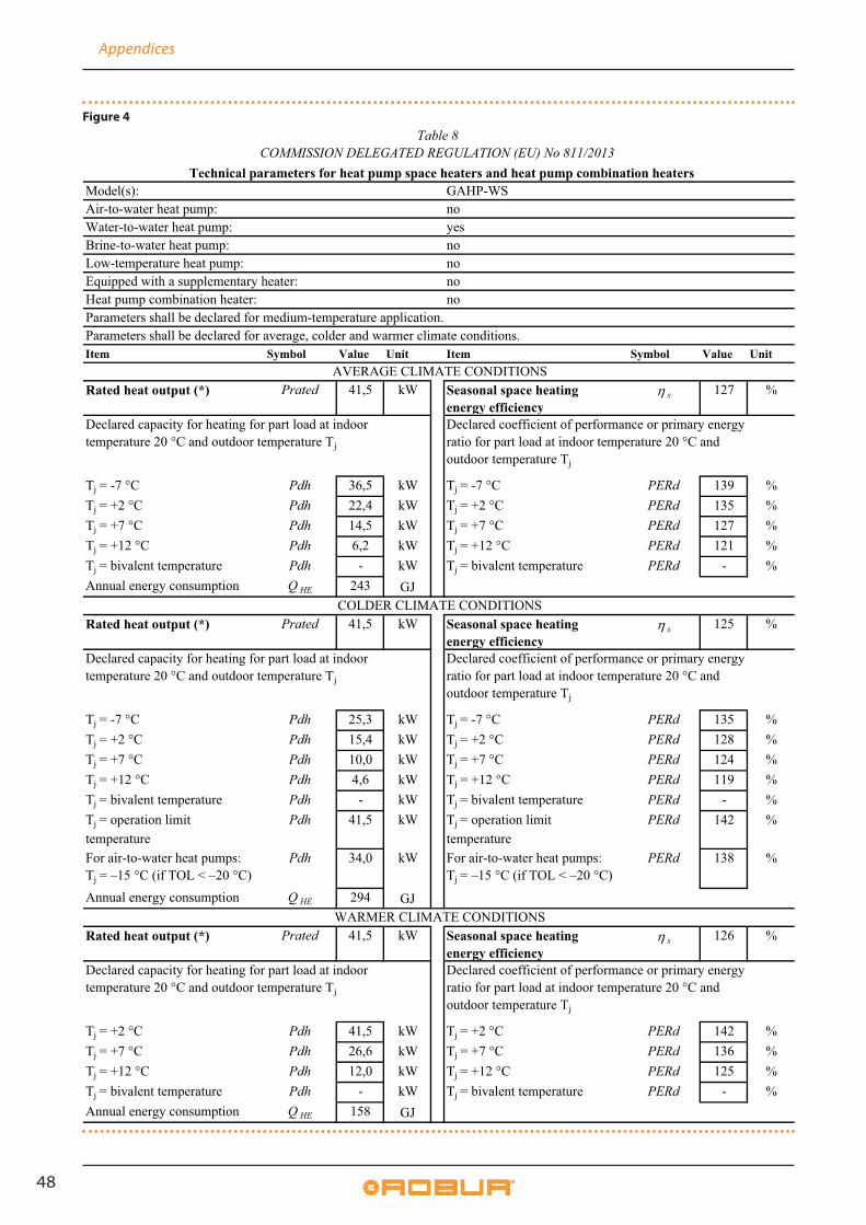
Appendices
48
Figure 4
Model(s): GAHP-WS
Air-to-water heat pump: no
Water-to-water heat pump: yes
Brine-to-water heat pump: no
Low-temperature heat pump: no
Equipped with a supplementary heater: no
Heat pump combination heater: no
Item Symbol Value Unit Item Symbol Value Unit
Rated heat output (*) Prated 41,5 kW Seasonal space heating
energy efficiency
η s 127 %
Tj = -7 °C Pdh 36,5 kW Tj = -7 °C PERd 139 %
Tj = +2 °C Pdh 22,4 kW Tj = +2 °C PERd 135 %
Tj = +7 °C Pdh 14,5 kW Tj = +7 °C PERd 127 %
Tj = +12 °C Pdh 6,2 kW Tj = +12 °C PERd 121 %
Tj = bivalent temperature Pdh - kW Tj = bivalent temperature PERd - %
Annual energy consumption Q HE 243 GJ
Rated heat output (*) Prated 41,5 kW Seasonal space heating
energy efficiency
η s 125 %
Tj = -7 °C Pdh 25,3 kW Tj = -7 °C PERd 135 %
Tj = +2 °C Pdh 15,4 kW Tj = +2 °C PERd 128 %
Tj = +7 °C Pdh 10,0 kW Tj = +7 °C PERd 124 %
Tj = +12 °C Pdh 4,6 kW Tj = +12 °C PERd 119 %
Tj = bivalent temperature Pdh - kW Tj = bivalent temperature PERd - %
Tj = operation limit
temperature
Pdh 41,5 kW Tj = operation limit
temperature
PERd 142 %
For air-to-water heat pumps:
Tj = –15 °C (if TOL < –20 °C)
Pdh 34,0 kW For air-to-water heat pumps:
Tj = –15 °C (if TOL < –20 °C)
PERd 138 %
Annual energy consumption Q HE 294 GJ
Rated heat output (*) Prated 41,5 kW Seasonal space heating
energy efficiency
η s 126 %
Tj = +2 °C Pdh 41,5 kW Tj = +2 °C PERd 142 %
Tj = +7 °C Pdh 26,6 kW Tj = +7 °C PERd 136 %
Tj = +12 °C Pdh 12,0 kW Tj = +12 °C PERd 125 %
Tj = bivalent temperature Pdh - kW Tj = bivalent temperature PERd - %
Annual energy consumption Q HE 158 GJ
Table 8
COMMISSION DELEGATED REGULATION (EU) No 811/2013
Parameters shall be declared for average, colder and warmer climate conditions.
Technical parameters for heat pump space heaters and heat pump combination heaters
Parameters shall be declared for medium-temperature application.
Declared capacity for heating for part load at indoor
temperature 20 °C and outdoor temperature Tj
Declared coefficient of performance or primary energy
ratio for part load at indoor temperature 20 °C and
outdoor temperature Tj
AVERAGE CLIMATE CONDITIONS
Declared capacity for heating for part load at indoor
temperature 20 °C and outdoor temperature Tj
Declared coefficient of performance or primary energy
ratio for part load at indoor temperature 20 °C and
outdoor temperature Tj
COLDER CLIMATE CONDITIONS
Declared capacity for heating for part load at indoor
temperature 20 °C and outdoor temperature Tj
Declared coefficient of performance or primary energy
ratio for part load at indoor temperature 20 °C and
outdoor temperature Tj
WARMER CLIMATE CONDITIONS
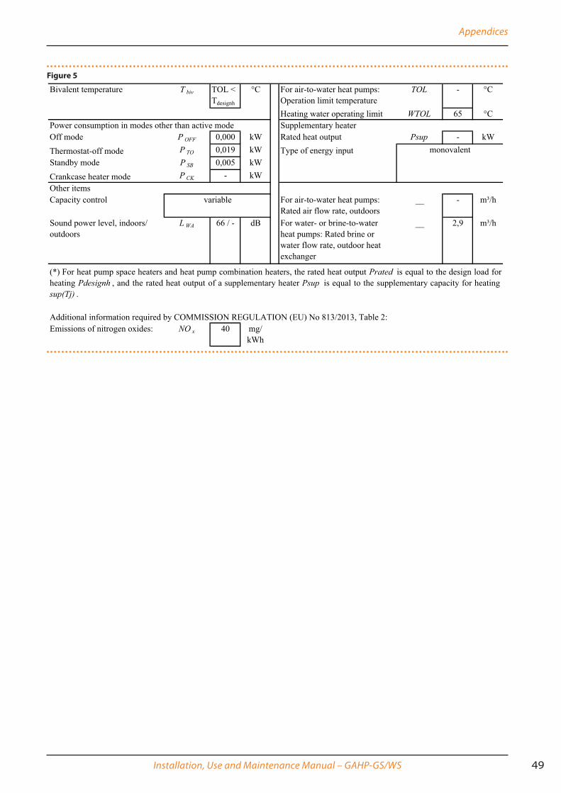
Appendices
Installation, Use and Maintenance Manual – GAHP-GS/WS 49
Figure 5
Bivalent temperature T biv TOL <
Tdesignh
°C For air-to-water heat pumps:
Operation limit temperature
TOL - °C
Heating water operating limit WTOL 65 °C
Off mode P OFF 0,000 kW Rated heat output Psup - kW
Thermostat-off mode P TO 0,019 kW Type of energy input
Standby mode P SB 0,005 kW
Crankcase heater mode P CK - kW
Other items
Capacity control For air-to-water heat pumps:
Rated air flow rate, outdoors
__ - m³/h
Sound power level, indoors/
outdoors
L WA 66 / - dB For water- or brine-to-water
heat pumps: Rated brine or
water flow rate, outdoor heat
exchanger
__ 2,9 m³/h
Additional information required by COMMISSION REGULATION (EU) No 813/2013, Table 2:
Emissions of nitrogen oxides: NO x 40 mg/
kWh
(*) For heat pump space heaters and heat pump combination heaters, the rated heat output Prated is equal to the design load for
heating Pdesignh , and the rated heat output of a supplementary heater Psup is equal to the supplementary capacity for heating
sup(Tj) .
Power consumption in modes other than active mode Supplementary heater
variable
monovalent

Appendices
50


Robur mission
Robur Spaadvanced climatecontrol technologiesVia Parigi 4/624040 Verdellino/Zingonia (Bg) ItalyT +39 035 888111∅F +39 035 884165www.robur.it [email protected]
Robur is dedicated to dynamic progressionin research, development and promotionof safe, environmentally-friendly, energy-efficiency products,through the commitment and caringof its employees and partners.
Re
visi
on: T
Co
de: D
-LBR
509
15M
CMSD
C013
25
/08/
2015


