Installation Practices* 11 Installation Practices.pdfSection III Covered and Insulated Aluminum Wire...
28
Section III Covered and Insulated Aluminum Wire and Cable Chapter 11 Installation Practices* Aluminum was first used on an overhead transmission line more than 85 years ago. Today virtually all overhead transmission lines have conductors of aluminum or alu- minum reinforced with steel (ACSR). The performance record of aluminum on overhead transmission lines led to its use in conductors of other types so that today most overhead distribution, service drop, and service entrance cables are aluminum. More recently, insulated aluminum cable has corne into wide- spread use in underground distribution and building wire applications. Aluminum building wire installation procedures are basically the same as those for copper. However, because aluminum is a different metal "ith different properties, several differences in installation practices must be fol- lowed. Connectors tested and approved for aluminum conductors must be employed and equipment to which aluminum conductors are to be connected must have terminals intended for use with aluminum conductors. Aluminum wire and cable are available in sizes to meet all needs and with the same types of insulation as copper (See Table lI-l). Connectors for all types and sizes of aluminum conductors and equipment with suitable ter- minals are available. Such equipment, UL-listed and designated for use with aluminum or copper conductor (ALlCU), and connectors designated "AL7CU" or "AL9CU" are available as stock merchandise in leading supply houses. The types and electrical properties of wires and cables used in secondary distribution and interior wiring circuits are listed in previous chapters. However, the dimensions for a wide range of sizes and various types of insulation are listed, for convenience, in Table 11-1. The method of '" FOr further infonnation On the installation of aJuminum building wire see the AA bookIet "Aluminum Building Wire Instailation Manual and Design Guide." connecting** a single wire or cable (or the individual conductors of a multi-conductor cable) to other conduc- tors or to switch-gear depends on the size of the con- ductor, the type of connector, and whether the compo- nents to be joined are both aluminum or one is of another metal such as copper. Aluminum Conductor Connectioll$ The electrical conductor has no functional value until it has been properly connected to complete the electrical circuit. Experience indicates that, apart from damage due to faulty installation or operation, most of the problems encountered in the field are at connections. Therefore, it is apparent that care taken in making a proper termination or splice is time well spent. A· similar record can be attained with insulated alu- minum conductors if there is proper attention to the connecting methods. The basic function of extending the conducting path is the same whether the conductor is bare or insulated, overhead or underground, inside build- ing walls, Or in cable trays or conduit. In the joining process, the oxide film on the contact surface of the aluminum must be ruptured to expose base metal. This fissured contact surface must be entrapped and collapsed against the adjoining contact member to establish metal-to-metal conducting areas. In addition, the joining process must protect these conducting areas against the degrading effects of service. In this respect the use of joint compound is most important. Its main function is to prevent the entry of moisture. Electrical connections are particularly vulnerable to this when the $>/I For purposes oftbis discussion, splicing and terminating will refer to conductors in circuits above 1000 volts which require not only connecting the separate conductor elements. but also the restoration of sometimes complex installation systems over tbe splice or terminal and, under some circumstances, application of added protection, Splicing and terminating are described separately. page 11-11 et. seq. ,,-,
Transcript of Installation Practices* 11 Installation Practices.pdfSection III Covered and Insulated Aluminum Wire...

Section III Covered and Insulated Aluminum Wire and Cable
Chapter 11
Installation Practices
Aluminum was first used on an overhead transmission line more than 85 years ago Today virtually all overhead transmission lines have conductors of aluminum or alushyminum reinforced with steel (ACSR)
The performance record of aluminum on overhead transmission lines led to its use in conductors of other types so that today most overhead distribution service drop and service entrance cables are aluminum More recently insulated aluminum cable has corne into wideshyspread use in underground distribution and building wire applications
Aluminum building wire installation procedures are basically the same as those for copper However because aluminum is a different metal ith different properties several differences in installation practices must be folshylowed Connectors tested and approved for aluminum conductors must be employed and equipment to which aluminum conductors are to be connected must have terminals intended for use with aluminum conductors
Aluminum wire and cable are available in sizes to meet all needs and with the same types of insulation as copper (See Table lI-l) Connectors for all types and sizes of aluminum conductors and equipment with suitable tershyminals are available Such equipment UL-listed and designated for use with aluminum or copper conductor (ALlCU) and connectors designated AL7CU or AL9CU are available as stock merchandise in leading supply houses
The types and electrical properties of wires and cables used in secondary distribution and interior wiring circuits are listed in previous chapters However the dimensions for a wide range of sizes and various types of insulation are listed for convenience in Table 11-1 The method of
FOr further infonnation On the installation of aJuminum building wire see the AA bookIet Aluminum Building Wire Instailation Manual and Design Guide
connecting a single wire or cable (or the individual conductors of a multi-conductor cable) to other conducshytors or to switch-gear depends on the size of the conshyductor the type of connector and whether the composhynents to be joined are both aluminum or one is of another metal such as copper
Aluminum Conductor Connectioll$
The electrical conductor has no functional value until it has been properly connected to complete the electrical circuit Experience indicates that apart from damage due to faulty installation or operation most of the problems encountered in the field are at connections Therefore it is apparent that care taken in making a proper termination or splice is time well spent
Amiddot similar record can be attained with insulated alushyminum conductors if there is proper attention to the connecting methods The basic function of extending the conducting path is the same whether the conductor is bare or insulated overhead or underground inside buildshying walls Or in cable trays or conduit
In the joining process the oxide film on the contact surface of the aluminum must be ruptured to expose base metal This fissured contact surface must be entrapped and collapsed against the adjoining contact member to establish metal-to-metal conducting areas In addition the joining process must protect these conducting areas against the degrading effects of service In this respect the use of joint compound is most important Its main function is to prevent the entry of moisture Electrical connections are particularly vulnerable to this when the
$gtI For purposes oftbis discussion splicing and terminating will refer to conductors in circuits above 1000 volts which require not only connecting the separate conductor elements but also the restoration of sometimes complex installation systems over tbe splice or terminal and under some circumstances application of added protection Splicing and terminating are described separately page 11-11 et seq
-
covered and insulated aluminum Wire and cable
TABLE 11-1 Nominal Dimensionsmiddot and Areas Aluminum Building Wire (Taken From 1987 NEe)
Bare Conductor TypeTHW TypeTHHN TypeXHHW Size
AWGor KCMIL
Size Number AWGor of KCMIL Strands
Oiam Inches
Approx Oiam Inches
Approx Approx Area Oiam
Sq In Inches
Approx Area
Sq In
Approx
I
Approx Diam Area Inches Sq In
8 7 134 255 0510 - - 224 0394 8 6 7 169 290 0660 240 0452 260 0530 6 4 7 213 335 0881 305 0730 305 0730 4 2 7 268 390 1194 360 1017 360 1017 2 1 19 299 465 1698 415 1352 415 1352 1
110 19 336 500 1963 450 1590 450 1590 liD 20 19 376 545 2332 495 1924 490 1885 210 30 19 423 590 2733 540 2290 540 2290 310 410 19 475 645 3267 595 2780 590 2733 40
250 37 520 725 4128 670 3525 660 3421 250 300 37 570 775 4717 720 4071 715 4015 300 350 37 616 820 5281 770 4656 760 4536 350 400 37 659 865 5876 815 5216 800 5026 400 500 600
37 61
736 940
613 1050 6939 8659
685
985 6151 I 860 7620 960
6082 600
7542 600 700 61 877 1110 9676 1050 8659 1050 6859 700 750 61 908 1150 10386 1075 9076 1060 9331 750
1000 61 1060 1285 12968 1255 12370 1230 11682 1000
Oullensioos are from industry $OUrces uCompact conductor per ASTM B 400 Artide 310-14 of the 1987 NEe calls for AA 8000 series electfical grade aluminum aHoy conductor material
power is off and the conductors are cool To the extent these are accomplished the connection will have low and stable contact resistance during its service life (For more information on electrical contact theory the reader is referred to the bibliography at the end of Chapter 13)
In this as in preceding chapters we will first consider conductors for secondary circuits (0 to 1000 volts) and the installation practices associates with them
Building Wire Connectors
Only pressure-type connectors marked AL7CU or AL9CU to indicate they have been tested and are listed by UL for aluminum copper or aluminum to copper connections interchangeably should be used The conshynectors are usually plated to avoid the formation of oxide and to resist corrosion
Pressure connectors are of two basic types--mechanshyical screw type and compression type applied with a tool and die
Both types are designed to apply sufficient pressure to shatter the brittle aluminum oxide from the strand surshyfaces and provide low resistance metal to metal eontact
Both basic types are suitable for usc with aluminum although many contractors believe that compression conshynectors are less susceptible to installation error
UL Slandard 486 covering connectors for use with aluminum wire has been revised A number ofconnectors have already been tested under the more stringent reshyquirements of the new standard UL 486B and are currently available
Installers are cautioned to avoid mechanical pressure connectors with too wide a range of wire sizes because the screw may not adequately engage the strands of the smaller conductors Installers are also advised to contact conductor manufacturers for recommendations concernshying specific connectors for use with their products
Connectors for every conceivable need are available Some typical connectors are shown in Fig 11-1 Whichshyever type you use follow the mannfacturers instructions carefully
Compression Connectors Aluminum conductors are particularly suitable for conshy
necting to each other or to an equipment terminal by use of solderless compression type sleeves because the conshyductor strands tend to weld together as a result of high compression pressure
Compression connectors similar to those used for bare conductors (see Chapter 5) arc widely used for conshynecting insulated conductors (Fig 11-1) Various styles are available along with special tools representing the system of a particular manufacturer Depending on
11-2
Compression Connectors
rEs
SPLICE
MECHANICAL COHHpoundCTOR$
TfES
CROSSOVER TEE OF PARALLEL TAP
TAPS
Fig 11-1 Connectors have been deshysigned and manufactured for every conceivable contingency Make sure connector is UL listed for alumishynum
the size of the conductors compression is obtained by use of hand tools Or from hydraulic pressure
Mechanical Connectors Pressure connectors of the setscrew or bolted mechanshy
ical type Fig 11-2 also provide a rapid means of making connections particularly where space is limited and where many taps are taken from a main as in panel boards or junction boxes Aluminum connector bodies are mashychined from extruded high-strength aluminum such as 6061-T6 The setscrews are of the Allen head type and tightening of screws or bolts by wrench compresses the aluminum conductor strands against the side wall of the
installation practices
recess causing the strands to intermingle Fig 11-l Mechanical connectors should be tightened to manufacshyturers recommended torque levels In the absence of manufacturers recommended torque levels values in Table JI-2 should be followed
Connector Plating UL standards require that connectors for use with
aluminum conductors be plated with tin or some other suitable contact metal and the face of any pad or lug that is plated should not be scratch-brushed but merely cleaned with a suitable solvent cleaner Scratching the plated surface is likely to remove the plating It should be noted that zinc plated connectors have an adverse effect on aluminum and should never be used on systems where aluminum wire is used
Building Wire Terminations
UL-listed terminal lugs marked AL7CU or AL9CU are used to connect aluminum conductors to transformers switches bus bar motors and other equipment Alumishynum terminals are usually plated and plated connectors should not be scratch-brushed or abraided
Like connectors they are of two basic types-meshychanical screw type and compression type applied by tool and die Some typical terminal lugs are shown in Fig 11-2 They are applied to the conductor ends in the same manner as described under Connectors
All equipment should be furnished with CL-listed all aluminum terminals Mechanical terminal lugs that are copper bodied and tin plated should not be used with aluminum conductors larger than 6 unless they have passed the 500-cycle requirements of new UL Standard 486B
Care should be taken that the conductor temperature and ampacity ratings are compatible with the terminals and equipment to which they are to be connected
When all components are aluminum (bus sluds lugs) only aluminum bolts should be used to make the conshynections
The following procedures should be used I Aluminum bolts should be anodized alloy 2024-T4 and
conform to ANSI BI821 specifications and to ASTM B 211 or B 221 chemical and mechanical property limits
2 Nuts should be aluminum alloy 606I-T6 or 6262-T9 and conform to ANSI B 1822
3 Washers should be fiat aluminum alloy Alclad 2024shyT4 Type A plain standard wide series conforming to ANSI B272 SAE or narrow series washers should not be used
4 Hardware should be assembled as shown in Fig IJ-3
11-3
--
covered and insulated aluminum wire and cable
Terminals
SCREWmiddotTVPE TERMINAL LUGS
reg
e ~o
COMPRESSION TERMINAL LUGS
c ~1f p~ ~ ~ ~ DiaMond
eire um1erefltl a HellgoflL Inderlted CompreSSIOII VersamiddotCrirnp
Fig 11-2 Typical plated aluminum terminal lugs corne in variety of styles
TABLE 11-2 STANDARD PRESSURE-CONNECTOR TORQUE TABLES
Tightening Torque For Scrsws
Toraue Pound-lnehe$ Slotted Head No 1 Q
and Lar98rb Hexagonal Headmiddot Slot Width-Inches External Drive
Socket Wrench To 3164 Over 364 Split-Bolt OthsrSfo~length-Inches
To 1 4 Over 14 Connectors~ Connectors
Torque For Slotted Head Screws Smatter Than No 10 For Use With Torque For No 10 AWG or Smaller Conductol$ Socket Head Screws
Torque-Lbmiddotlnches
Screwshy Screww$lot Wklth-lnche5 Slot
Longth- Less More Inchesc Than 3164 Than middot364
To 5132 5132 3116 7132 114 9132 932 +
7 9 7 12 7 12 7 12 9 12 - 15
- 20
Socket Size Across Torque
Flats~ Pound-Inchesnehss
45 5132 18
100 316 120 7132 150 114 200
275 318 5116
375 112 500 916 600
a Clamping screws with mutiple tightening means for example for a slotted hexagonal head screw use the highest torQue value associated with the different tightening means
b For values of slot width or length other than those specified select the largest torque value associated with conductor size
c For slot lengths of intermediate values select torQues pertajn~ ing to next shorter slot length
20 35 6018middot10 AWG 40 608 25 45 165356 45 1654 -
2753 50-275-2 60 2751 50-38510 50-38550210
50- 500310 50- 500410
- 65050250 komi 300 350 400 500 500 700 750 600 900 1000 1250 1500 1750 2000
65050-50 650 50
-625
50 625 100050-
50 1000 50
-1000 110050-110050-
- shy
1100 1100
50 -1100- -1100 1100
- --
75 75
110 110 150 150 150 160 160 250 250 325 325 325 325 375 375 375 375 500 500 500 500 600 600 600
Note The torque abes presented here are taken from UL Standard 4868 but are representative of Ihose pLbllshed in other UL Standards in NEMA equipment installation instruction publications and In the Canadian Electrical Code The same values apply to pressure connectors tor both copper (UL Standard 486A) and aluminum conductors
11-4
1 AlumInum Bolt 2 Alummum Washer 3 Aluminum Bus 4 Aommum tug 5 AlumllHJm Wbshel 6 Alumitlum Nut
installation practices
TABLE 11-3
Lug Bolting Torque
Bolt Diameter
nth
Tightening Torque PoundmiddotFeet
14 or less
516 318 7116
112 58 or more
6 11
19
30 40 55
Fig 11-3 When all components are aluminum aluminum hardware should be used and installed as above
5 All hardware should be suitably lubricated before tightening
6 Bolts securing lugs should be tightened to the manushyfacturer-s recommended torque In the absence of such recommendations torque values listed in UL 486 Standards should be used (See Table 1I-3)
If adding to an existing installation containing copper bus or studs or if it is impossible to obtain the required equipment with aluminum terminations then a steel bolt should be used with a Belleville spring washer to allow for the differing rates of thermal expansion of the mateshyrials The following procedures should be used
1 The steel bolt should be plated or galvanized medium carbon steel heat treated quenched and tempered equal to ASTM A 325 or SAE grade 5
From Ut 4S6 Standards
HOTE Ii bOilS are nOllubricaled with sUiton spray Cf clner suitable lubricant torques may fary widely atld resu Igt high (lon-tacl resistance lt11 joinls
2 Nuts should be heavy semi-finished hexagon conshyforming to ANSI BI822 threads to be unified coarse series (UNC) class 28
3 Flat washers should be steel Type A plain standard wide series conforming to ANSI B272 SAE or narrow series washers should not be used
4 Belleville conical spring washers come in sizes for use with bolts ranging in sizes indicated in Table 11-4
5 Hardware should be assembled as shown in Fig 11-5
6 All hardware should be suitably lubricated before tightening
7 In the absence of specific manufacturers instructions bolts should be tightened sufficiently to flatten the spirng washer and left in that position
TABLE 11-4
BELLEVILLE SPRING WASHERS
Bolt size 00
Thickshyness
Lb nom load
to flat
In-Ibs torque to flat
li4
516
38
12
58
1116
1316
1516
1middot316
1middot12
050 060 070
085
100
800 WOO
1400
2700
4000
50middot75 125-150
150middot175 17520C
222middot250
Note Torque valueS to be used as guides only Actual installation conditiQns will vary considerably Bolt should be tightened until a sudden increase in torque 1$ felt In this manner no torque wrench is required and washer will be flaHened
Materia Hardened Steel Table Courtesy of Thomas amp Betts Co
11-5
covered and insulated aluminum wire and cable
Fig 11-5 Belleville washer is used to make an aluminum-ta-copper or steel joint Note Crown of Belleshyville washer should be under the nut
With equipment having terminals that will accommoshy aluminum bolts and nuts are used only the heavy washer date only copper conductors a gutter splice may be bearing on the aluminum lug is necessary used to connect the aluminum conductor The aluminum Figures 11-7 to 11-12 show some typical connections conductor is spliced to a short length ofcopper conductor of aluminum conductors to equipment terminals and the copper conductor stub is then connected to the
Because of the differing rates of thermal expansion ofequipment terminal (Fig 11-4) An AL7CU or AL9CU aluminum and other conducting or support metals it is compression type connector is used to make the splice preferable to have all parts of the circuit including studs
Instead of a gutter splice onc of the many UL-listed and clamp bolts of aluminum The aluminum bolts should AL7CU or AL9CU adaptor fittings specifically designed be of alloy 2024-T4 and the nuts compatible though for this purpose may be used (Fig 11-6) preferably not of identical alloy and temper Bolts and
For connecting large aluminum conductors (500 kcmil nuts should be of heavy series design to reduce stress and up) to heavy equipment having copper terminal studs beneath the head NC (coarse) threads are preferred for andor pads large compression type lugs preferably with the 2024-T4 aluminum bolts Components should be two holes should be used in making such a connection assembled as shown in Fig 11-9 More information about (Fig 5-2) With other than aluminum bolts Belleville aluminum bolted connections will be found in Chapter spring washers and heavy flat washers in consecutive 13 arrangement as shOm in Fig 11-5 must be used If
Fig 11-7 Where possible current transformer terminals should be reshyplaced with compression type (B) If not possible 0 remove section of copper cable should be spliced to aluminum (AJ
Fig 11-8 Power transformer ter- minals ifcopper must employ short copper stub spliced to aluminum L___~~~~~=-_Jcable
Fig JI-4 Gutter splice is used when terminal lugs are not removable and are approved for copper cable connection only
~lO ~ t 2 3 fi5
Crown Facu ut
t Aluminum IY ~ BlI$ (or stud) 2 Sfe1l1 or CQPper St 3 AIminvM Lug 4 St~iJl Flat Washef 5 Steel Selleville 6 Sleel Nut
Fig 11-6 There are a number of UL-listed adaptor jittings available for use with terminals not suitable for direct connection of aluminum conductors
11-6
installation practices
Fig 11-9 When connecting alushyminum conductors to a unit subshystalion with copper bus use compression type aluminum lugs attached with a steel bolt a fiat washer and a Belleville washer (A) Copper primary leads on transshyformer are connected to aluminum feeders in aluminum connectors and bolted back-to-back using a steel bolt a fiat washer and a Belleville washer (B)
Basic Installation Techniques
Fig 11-10 Three methods of makshying motor connections are shown in detail A All terminals are prefshyerably aluminum Where bolt is steel or copper Belleville washer is necshyessary (B)
Fig 11-12 Copper lug connections on switchgear are repaced with equivalent aluminum connectors Belleville washer is used with copshyper or steel studs
1 Stripping Insulation
Never use a knife or pliers to ring a conductor when stripping insulation One way to avoid this is to pencil or whittle the insulation (Fig 11-13)
Another method is to skin the insulation back from the cut end of the conductor and then cut outward (Fig 11-14)
Several types of insulation stripper are available for quick easy removal of insulation One of these useful for small size conductors is shown in Fig 11-15
2 Making Connections
Preparation of aluminum conductors for connection to an equipment terminal or another conductor requires stripping of the insulation and rupture and dispersal of the nonconducting oxide film that appears quickly on a fresh aluminum surface exposed to air Care must be taken not to nick the wires when removing insulation in order to avoid broken strands in installation or service Seveltl types of insulation stripper are available for quick easy penciling or square-cut removal of insulation One type is shovn in Fig 11-16
Abrading the conductor strands with a wire brush or other appropriate tool will serve to clean the conductor
and disperse the oxide coating prior to application of joint compound
The conductor end is then inserted into a compression sleeve of adequate thickness or a suitable mechanical type pressure connector If the connector does not come factory-filled with an acceptable joint compound such paste should be applied to the conductor end before insertion into the connector (Some manufacturers conshynectors may not require the use of compound but it should be used in the absence of specific instructions to the contrary) The compression sleeve should then be compressed with a hydraulic compression device or the setscrew of a mechanical connector tightened in a manner prescribed by the connector manufacturer Excess comshypound should be removed from the conductor insulation but not from the joint itself where it will serve to prevent air from entering
Solid aluminum wires are prepared in a similar manner and the smaller sizes may be fastened under a bindingshyhead screw (without joint compound) after looping in a clockwise direction
Note The ALiCU or AL9CU marking is not required on equipment connectors However the equipment in which they are installed must indicate suitability for use with aluminum and connector tightening torques
11-7
covered and insulated aluminum wire and cable
Fig 11middot13 Never ring a cable-it may lead to a break Insulation should be removed as one would sharpen a pencil
Fig 11-14 Another safe way of removing insulation from conducshytor is to peel the insulation back and then cut outward
Fig 11-15 Use wire stripper for removing insulation from smaller wire sizes Match stripper notch to wire size
Fig 11-16 Penciling tool for removal of insulation in bevel configuration by rotation Several sizes are availshyable which by proper selection ofbushing are applicable to all usual sizes of cables This tool is particularly suitable for primary cables which have comparatively thick insulation
In making connections first strip the insulation as instructed heretofore Then apply joint compound if it is not already contained in the connector
If the connector is a mechanical screw type appJy the manufacturers recommended torque (Fig 11-17) In absence of specific torque recommendations use UL 468B torque values shown in Table II-I Ifacompression type crimp it as recommended by the manufacturer (Fig 11-18) Be sure to select the correct size die and close the tool completely for full compression Wipe off any excess compound Then tape the joint as instructed under Section BZ Or apply the inSUlating enclosure that comes with some types of connectors
3 Pulling Conductors in Conduit or Electrical Tubing
The following procedures are applicable to conduit of all types including aluminum
a Run a fish line through the conduit This may be done by attaching the line to a piston-type device which is propelled through the conduit by compressed air Another method is to push a round flexible speedometer type steel wire through the conduit Polyethylene fish tapes may be used for shorter runsshyup to about 100 feet
b Attach a clean-out brush to the fish line and behind it attach the pull line then pull both through the conduit by means of the fish line
c Attach the pull line to the conductor or conductors A basket grip over the insulation may be used for this purpose (Fig 11-19)
11-8
installation practices
Fig 11-18 Crimping tool must be fully closed Failure to close crimpshying 1001 will lead to an unsatisfacshytory and weak joint
Fig 11-17 Proper torque is imporshytant-over-tightening may sever the Fig 11-19 Basket grip wires Or break the filling undershytightening may lead to overheating and failure (See Table 11-2)
d Where conductors are pulled with a rope stagger j When conductor ends are prepared for pUlling be sUre the conductor ends and anchor in position with tape not to nick the stranded aluminum conductor during to provide maximum lIexibility around bends (Fig insulation removal Damaged strands can reduce the 11-20) pulling tension capabilities of the conductor To avoid
this pencil the insulation for removal as described above do not ring cut the insulation
k Follow all NEC requirements
Fora detailed description ofcalculating pulling tensions see the example given on page 11-11 on underground installations See Chapter 17 for a complete treatment of aluminum conductors in conduit
Fig 11-20 When a rope pull has to be used skin the cable ends and stagger them after locking with tape 4 Installation of Cables in Trays This will hold tie to a minimum Where aluminum cable is to be pulled in trays or cablecross section racks take the following precautions plus those applishy
cable to conduit e Try to feed conductors into conduit end closest to the a Where pulling attachments are used on the conductors
sharpest bend to reduce pulling tension cover them with rubber-like or plastic tapes to prevent pound Have pulling equipment with adequate power available scoring of the trays and installation sheaves during a
to make a steady pull on the cables without jerks conductor pull during the pulling operations b Use large-radius sheaves around bends and smaller
g Use pulling compound compatible with the conductor sheaves on the straight sections of cable support trays insulation as the conductors are fed into the conduit to facilitate cable installations to reduce the required to reduce coefficient of friction and required pulling pulling tensions and to prevent damage to stranded tension conductors or insulations
h For single conductors on a reel stagger reels one c Where cables are anchored on trays be sure straps behind the other while feeding in conduit to maintain or other cable anchoring devices do not cut into the equal pulling tensions and prevent conductors from insulation crossing over and jamming in the conduit d Cables installed in trays should follow the requireshy
I Wherever possible pull conductors in a downward ments of NEC Article 318 for the aUowable number direction to allow gravity to assist in pulling with of cables permitted in trays and their respective reduced tension ampacities
11middot9
covered and insulated aluminum wire and cable
e Straight cable tray runs may often be installed by simply laying thelightweight aluminum cables in place
f Be sure tray supports are capable of handling maxishymum weight of conductors and planned conductor additions in the future
5 Minimum Training Radii
Where permanent bends are made at terminations using aluminum building wire Table 11-5 indicates the minishymum bending radius as a multiple of the overall cable diameter Such bends should be made before the terminal is applied to minimize electrical contact distortion
6 Conductors in Vertical Raceways
The NEC under section 3()()19 stipulates that conducshytors in vertical raceways shall be supported As a general rule one cable support shall be provided at the top of the vertical raceway or as close to the top as is practical plus an additional support for each interval of spacing as shown in Table 11-6 An exception to this rule is that if the vertical riser is less than 25 of the spacing listed in the Table nO cable support shall be required
Installing Cable in Conduit or Duct
Theprocedures forinsertinga fish line or tape through a conduit or duct followed by a pull line andlor cable as required for the pull are well known and established as field practice and do not need extensive description here Aluminum conductors may be attached to pull line or cable by means of a factory-installed pulling eye by placing a basket grip around the conductors insulation (Fig 11-21) or by tying the line to a loop in the uninsulated part of the conductor (Fig 11-20) Steel pull cables used to pull conductors around bends in aluminum conduit runs may damage the conduit at the bend This is often avoided by using steel elbows with aluminum conduit or by use of a pull line that will not damage aluminum elbows
Pulls should be accomplished with steady tension and pulling speeds not exceeding 50 feet per minute Hard pulls can be eased if the reel if hand controlled and slack cable is guided into the conduit
Pulling tensions may be reduced by lubricating the cable surface However SOme lubricating materials have been found to adversely affect cable insulations or outer jackets In addition to cable pulling compounds this
TABLE 11-5 TRAINING RADII
For 600 V Cable Not in Conduit on Sheaves or While Under Tension
POWER CABLES WITHOUT METALLIC SHIELDING ON ARMOR The minimum recommended bending radii as muHiplies of 1I1e overall cable diameter given in the following tabulation are for both single and multi-conductor cable with or without lead sheath and without metallic shielding or armor
Minimum Training Radius Thickness of as multiple of cable diameter
Conductor Insulation Overall Diameter of CAble-Inches mils 1000 and Less 1001 to 2000 2001 and over
155 and less 4 5 6 170 to 310 5 6 7 325 and over 7 8 I
POWER CABLES WITH METALLIC SHIELDING OR ARMOR (a) Interlocked Armored Cables
The minimum recommended bending radius for all interlocked armored cables is in accordance with table above but not less than 7 times the overall diameter of the cable except as noted below (c) for tape shielded cable
(b) Flat Tape and Wire Armored Cables The minimum recommended bending radius for all flat tape armored and all wire armored cables is 12 times the overall diameter of cable
(c) Tape Chielded Cables For ali cables having metallic shielding tapes the minimum recommended bending radius is 12 times 1I1e overall diameter of the completed cable
(d) Wire Shielded Cables Wire Shielded Cables should have the same bending radius as power cables without metallic shielding tape Aepfilted loon ICEA 5-66-524 NpoundWA WC-7
11-10
instollation practices
TABLE 11-6
SUPPORTING CONDUCTORS IN VERTICAL RACEWAYS From 1987 NEe Table 300middot19 (a)
Conduelors
Aluminum Copper
No 18 to No B Not greater than 100 feet 100 feet
NO6 to No 0 Not greater than 200 feel 100 feel
No 00 to No 0000 Not greater than 180 feel 80 feet
2116 kernil to 350 kernil Not greater than 135 feet 60 feet
350 kernil to 500 kernil Not greater than 120 feet 50 feet
500 kernil to 750 kernil Not greater than 95 feet 40 feet
Above 750 kernil Not greater than 85 feet 35 feet
applies to potting and joint compounds adhesives tapes etc If in doubt compatibility of materials foreign to the insulation should be cleared through the cable manufacmiddot turer
A number of proprietary wire puUing lubricants and compounds are UL-listed and labeled to indicate the compounds compatibility with conductor coverings In all cases the manufacturers instructions should be obmiddot served
Allowable Pulling Tension
The following formulas can be used to calculate the maximum allowable tension that should be applied to the cables Note that these allowable tensions assume the pullshying eye is attached to the conductor Where the pulling line is attached to a basket grip that surrounds the insulation the pulling tension should not exceed 1000 100 It should be kept in mind that tension developed for straight runs per unit length is less than that for the portion of the cable in bends
L The maximum aJ~owable pulling tension if the pulling eye is aHached to the conductor
(Eq Hmiddotl)
where Pm Maximum allowable tension lb N Number of conductors being pulled simultaneously A Circular mil area of each conductor
(If conductors are of various sizes add the individshyual NA values)
K = Conductor stress factor
2 The maximum allowable pulling tension (Pm) cannot exceed 1000 Ib where cables are pulled with a basket grip however the tension per Eqs 11-1 or 1t-2 should nOL be exceeded
3 The matimum allowable pulling tension for cable in conduit
or duct bends (to prevent cable damage becallse of rubbing on sides of bend) must not exceed the following
Ib = 100 r (Eq Hmiddot2)
where Ptgt = Maximum allowable bend tension Ib r = Radius of curvature of the conduit or duct bend ft
Note The maximum aIIowable tension determined from Eqs 11-1 or 1l~2 should not be exceeded
4 For straight section of conduit or duct the pulling tension (lb) likely to be developed can be determined as follows
P=L w t (Eq Hmiddot3)
where p~ = Pulling tension in straight section Ib L Length of conduit or duct straight section ft 1 = Weight of cable (or cables) lb per ft t = Coefficient of friction
Note For a wen constructed conduit or duct with a lubricated cable f approximates 05 For less favorable conditions or with considerable curvature f may approximate 075
5 For curved sections of conduit or duct the pulling tension (lb) likely to be developed can be determined as follows
Ic =1 + 1 eta CEq 1l-4) where Pc = Total pulling tension Ib
Ps = Tension for straight section at pulling end Ib PI = Tension for straight section at feeding end Ib = Angle of bend in radians (I radian = 573 deg) e = Base of Naperian logarithms (2718) f = Coefficient of friction
Example Determine the maximum pulling tension required to install three single-conductor cables in a duct according to the arrangement in Fig 11-22 The cable specifications are
Three single conductor 40 AWG 600-volt aluminum cables with cross-linked PE insulation
Weight 3 290 IbM It = 087 Ib per ft Cable diameter each 0690 in
Coefficietlt of friction=O5 K valueQOOSshy
middotK 0008 for ~ hard aluminum conductors or 0004 for Y2 or J4II
hard aluminum
iIgtiFfR ~o 5 11-11
covered and insulated aluminum wire and cable
A Condttj~ or Doct Ckan)Ot Brush
B Kellems Grip
C Job Famianed Pulling BlUket
Fig 11middot21 Pulling cable in duct Pulling cable between junction boxes of conduit installations is similar
Using a single pulling eye attached to the three conductors and applyshying Eq 11~1 the maximum allowable pulling tension is
Pm=0008 X 3 X 211600=5078 Ib per Sq IImiddot I For the entire run from pull-box (I) to pull box (6) the tension
increments are as follows Sq
11middot3 At box (2) p == L X w X t == 100 X 087 X 05 == 435 Ib
f 0 05 X 1S71 11-4 At box (3) p == P X e = 435 X e
435 x 2194=954
11middot3 At box (4) P = 954 + (4 X w X tJ == 954 + (SO X 087 X 05) = )J72 Ib
0$ X 1571 114 At box (5) p == 1172 bull = 1172 X 2194 =
257llb
11middot3 At box (6) P 2571 + (4 X w X f) = 2571 + (15 X 087 X 05) = 2637 Ib
The total puning tension of 254 lb is far below the 5080 Ib limitation and the tension at each bend is far below the
11-12
recommendation per Eq 11-2 of 100 x 10 or 1000 lb Study of such examples shows that there is an advantage in puning cables from the pull box or manhole closest to the first bend This aids in reducing tension on the installed cable In this instance if the pull started at box (6) the final tension would be about half the above-found value
For a more complete treatment of cable puning in conshyduit the reader is referred to RC Rifenberg AlEE Tranmiddot sactions Dec 1953
Installing Directly Buried Power Cables
If cable placement can be started Defore sidewalks and other obstructions are installed the plowing-in method usually is the most economical method of burying power cable If soil conditions are unsuitable for plowing the
See also Aluminum Underground Distribution Reference Book
PULL BOX
50
PULL BOX
Fig 11-22 Diagram ocircuit layout to illustrate method of computing pulling tension
use of trenchers back hoes Or manual digging is custoshymary If the soil is rocky it should be screened to prevent cable damage Int is not sufficiently fine to closely cover the cable surface a four-inch thickness of sandy loam placed under and over the cable will improve the heat radiating quality of the soil
Duct Or conduit also should be used under streets or where access by digging to a buried cable is not practicable
Sufficient cable slack should be provided at risers and terminals to permit earth movement that may occur because of conductor thermal expansion frost and also as an allowance for future repair
Boards or slabs placed over the cable for mechanical protection should not be directly in contact with the cable but should be laid on an earth fill over the cable
Depth of burial ranges from about 30 to 48 inches for primary cable and from about 24 to 42 inches for secshyondary cable when buried separately On many systems both primary and secondary cables are buried in the same trench with no separation In many areas the trenches are shared jointly with other utilities notably communishycations-both telephone and television cables Joint use of trenches requires close collaboration on installation schedules but offers substantial economies to the sharing utilities
Initially a separation of one foot was required between primary power and communication cables and many comshypanies still require this separation An amendment to the NESC however permits random-lay (no deliberate separation) installation of communication and power cables in the same trenches with grounded wye power systems operating at voltages not in excess of 22 leV to
installation practices
ground ordelta systems operating at voltages not in excess of 53 kV phase to phase under certain conditions describshyed in NESC Section 35 Article 354 However joint use with very long single-phase primary circuits is not recomshymended because of the inductive pickUp of harmonics by the communication cables from the power cables
Care exercised in handling the cable during installation will help to avoid trouble later for damage sustained by the cable during installation has proved to be a major cause of subsequent cable failure
Many of these precautions have to do with making sure there is no insulation damage The cable is not susceptible to corrosion failure when insulation is unbroken even where moisture has gained entry into the conductor is some manner this fact has been determined in cable manufacshyturer laboratory tests and from research by utilities Migrashytion of moisture through damaged insulation in the presence of ac potential concentrates ions and promotes ac electrolysis
Cable transitions between overhead and underground usually employ the conventional factory-molded pothead of which special types are available for use in URD systems A termination is not reqnired however if the insulated aerial cable is also suitable for direct burial Such a cable can be carried directly down the pole Riser shields or conduit should be used to protect the cable on the riser pole to a point at least eight feet above ground level and should extend at least 12 inches below ground The riser shield must be solidly grounded to the system neutral and bonded to the lightning arrester to avoid transient potentials
Many other practices relating to buried cables and their connection to transformers to service entrances and tap connections in junction boxes and vaults are described in industry manuals Practice is gradually becoming standshyardized in the direction of increasing reliability and lowershying installation and maintenance costs in this most imshyportant segment of power distribution
The following suggestions will help to avoid failures from this cause they apply equally to cable and cable in pipe
1 Make sure that end seals are intact both while the cable is stored and installed to avoid entrance of water into the strands
2 If plowing is not used cables if at all possible should be payed out along the side of the trench from moving reels or carefully laid in the trench from stationary reels
3 The trench should not be dug before final grading is determined so cable will not be exposed or be too close to the surface
bull See also IEEE Conference Record 31C35 Special Technical Conference on Underground Distribution Sept 27~29 1966
11-13
covered and insulated aluminum wire and cable
TABLE 11middot7
I ICEA MINIMUM BENDING RADII FOR POWER CABLES
WlTHOtIT METAlliC SHIELDINGmiddot
I Minimum Bendine RHii as a Multiple of Cable Diameter
I cabl DO Inchbullbull
Tlllcimess of 1000 1001 2001 i
Insulation Inch I and less tD 2000 and OYer
0156 and Ie 4 5 6
I 0157 to 0312 5
i 6
7 0313 and over - 7 S
bull Only applicable for cable training bearing pressure limitation may require larger bending radii for cable tension
Data apply to single and multiple conductor cable also to wire-shielded cable Minimum bending radius for cables with metallic shielding tape is 12 Urnes the completed cable 00 The National Elecshytrical Code Section 300-34 requires 8 times fot non-Shielded and 12 times for shielded medium voltage cable bending radiI
4 In rocky soil areas use screened backfill Or sand to protect direct buried cable A 2-inch bedding is sufficient below but there should be a minimum cover of about 4 inches (The bedding and cover can be omitted when duct in conduit is used)
5 If boards concrete slabs etc are used above the cable for mechanical protection they should not be in direct contact to avoid shearing action when the soil settles Make sure boards are treated with preshyservatives that will not harm the cables insulation
6 Check the cable visually for damage before burial or installation in duct
7 When primaries are pulled into ducts or open trenches the use of a pulling grip over the cable is common rather than a pulling eye or other attachment conshynected directly to the conductor Duct should be carefully cleaned by pulling a plug through it to remove all burrs and obstructions To keep the cableshypulling tension within safe limits a lubricant approved for use with the specific insulation and insulation shield should be used
8 When doing permanent training make sure that the minimum bending radii are observed (see Table 11-7) Make every effort to provide more radius than these values at reel payout risers plow guides duct bend etc
9 Make sure splices and other connections are made in accordance with manufacturers recommendashytions
10 Double check to make sure proper backfilling is done Rock fill should be kept away from the cables to
prevent damage Compacting should be carefully done and air spaces minimized
11 Proof test the cable after installation to insure integshyrity of insulation and splices (See Table 11-8)
12 Dont overfuse the cable Because of the paucity of failures many utilities prefer to use one-shot fuses as an added protective measure for the cable
Many of these precautions have to do with making sure there is nO insulation damage The conductor in 600 volt cables is not susceptible to corrosion failure when insulation is unbroken and moisture has not gained entry into the conductor When moisture enters a break in insulation however ac electrolysis begins
Splicing and Terminating in Underground Systems
The revolution in underground distribution system design has included the devices and methods used for making splices connections and terminations The obshyjective here has been to reduce the amount of skill and time required in the field so as to reduce the installation costs More prefabrication is being done under factoryshycontrolled conditions and the need for heating and pouring of insulating compounds or extensive taping in the field has been greatly reduced
Aluminum connectors and terminating devices should be used with aluminum conductors so as to avoid differshyential thermal expansion and contraction upon heating and cooling that could result from the use of connectors of dissimilar metals Compression type connectors and lugs applied with a tool and die are widely used It is
11-14
instolation practices
TABLE 11middot8
ICEA RECOMMENDED de PRooFmiddotTEST VOLTAGES (15 Minute Test)
Polyethylene or CrossmiddotLinked Polyethylene Insulatd cables
ProofmiddotTestRated Insulation Voltage 1mCircuit Thicllnm (Mils)Voltage Installation
i
25 5001middot 8000 115 2001middot 5000 90
35 8001middot15000 175 55
15001 middot25000 80 25001 middot28000
260 85280
28001middot 35000 345 100
important in installing these devices that a die of the correct size be used and full pressure be applied in order to obtain permanently sound connections
600 Voll Secondary Clrcuils
In this regard connector manufacturers have made important advances in the design of connection devices for secondary circuits There are far too many types to describe them all in this handbook However a couple of examples are given below to indicate the types of premiddot molded splices and terminations that are currently availmiddot able for this type of service
(a) Underground Direct Burial Splice 600 volt insulated cable splices are available for conductor sizes 6 AWG stranded through 1000 kcmil and can be completely installed and sealed without taping or compound filling Typical installation procedure is (Fig 11middot23) as follows
Step A
Lubricate both insulating splice caps by applying a small amount of the supplied lubricant to the inside diameter of the cap at both the housing end and also to the inside diameter at the conductor hole end For easier assembly of the insulating caps to the conshyductor jt is recommended that the insulation at the end of the conductor be penciled before stripping Then place the proper caps over each conductor end
Step B
Strip correct length of conductor insulation for the splice connector being used Place splice housing over end of conductor and assemble one cap to housing Large end of cap should cover the knurled line of the housing body
Step C
Wire brush exposed cable ends and then immediately
insert cables into connector Start crimping splice onto conductor as per manufacturers instructions Continue crimping to ends of splice overlapping crimps 118 inch minimum Wipe away all excess oxide inhibitor
Step D Place housing with the assembled cap over splice connection and snap remaining cap in place on housing to complete the sealed splice When caps are correctly installed the large ends should cover the knurled lines on both ends of the housing body
(b) Secondary 600 V Underground Terminations There are several different designs of connector products which are approved for use in underground 600 V electric power systems They supply the needs of connectors required for residential or commercial use direct burial below grade vaults pedestal or pad mounted equipment bolted or compression fittings and in any combination
Fig 11-24 shows a representative group of these fittings which are designed to accommodate a wide range of conductors Their installation is straightforward and reshyquires no field cutting or hand taping for insulation or environmental sealing The threaded stud connector for transformers is such that the connector can be detached from the transformer without disconnecting the conducmiddot tors
Primary Circuits
Termination of primary underground cables requires some type of stress relief Initially these were made up by taping a stress cone which proved to be one of the most tedious and time-consuming jobs for the field man Today most utilities use some form of preshaped Or prefabricated stress cone which can be installed in a fraction of the time
11-15
-----------
covered and insulated aluminum wire and coble
B IN4fyenSUIATlNGCAP rNO PENCILING
__ bull ( REQUIRED
- -f -- -~I L
c - ~ _shy
D
STRIP os lENGTH
INSUATINi CAP KNURLED LINES
- - - - -HHH+shy~ SPUCE HOUSING
~~~-~~~-$PUCE CONNECTOR INSULATING CAP bull----- E--- KNURLEO
LINES
l__________________________________________________________~c~ou_n_e~~8~la~Ok~b_ria~n~C~O~_J Fig 11middot23 Secondary 600 V Underground Splice Kit showing sequence of assembly steps
Typical terminations for primary cables indicate that molded precut tape and porcelain types are used indoors while porcelain units are most often used outdoors One of the most significant developments in primary cable terminations has been the introduction of plugmiddotin conmiddot nectors for joining the cables to equipment or other cables With these devices it is almost as easy to conncct a primary cable as to plug in or remove an appliance cord from a convenience outlet
11middot16
The concept of premolded stress relief takes the fabshyrication of a stress relief COre away from the field and into the factory with its controlled environment leaving just the assembly to the field installer Elastomeric conshynections form a very convenient inexpensive and reliable method of connecting or terminating high voltage cables Power cable loadbreak elbows in the 35 kV class were introduced to the industry in 1983 with designs for 15 kV and 25 kV following in 1985
installation practices
CAP for porcelain bushings
Set screw s In seu connector are light shyened dow n on flat side 01 Adapter pressure deforms Adapter to lock Ad~pter and seu conneCtor to threaded stud un screws can be b8 C k~d -ofl Adapter and seu conn eCt or removed from transformer without remo ving conductor from connector
Thr eaded Stud Secondary Bush ing
l Adapter Scr6W5 on threaded tud of bllshing Iat side 01 Adapter mUSt be oriented to receive sel Ic rews
seu connector slips o ver Ad apUlr All Adapters have ~
0-ring5 In Sealing Cep same 0 0 all seu con shyseal arond Bushing neclors ho ve seme Adepter Neck and seu connector cavit y 10
Fig -24 Some typical 600 V underground termination fillings
Through the combined efforts of the connector and Some typical applications of premolded products are apparatus manufacturers and the utilities there is availshy at pulling or junction boxes cable to equipment connecshyabte today an array of premolded products that exhibit a tons and cable to cable connections All of these comshyhigh degree of safety reliability and flexibility ponents are designed and tested to be in compliance with
ANSUIEEE Standard 386-1985 Separable Insulated middotSee James W Fitzhughs paper Exploring the Application of Connectors for Power Distribution Systems above 600 Premolded Products for High Voltage Power Systems Volts
11-17
covered and insulated aluminum WIre and cable
Prlo(o counesy 01 ELASTIMQLO
Fig -25 Power cable joint for use af 15 k V or 25 kV
Primal( Voltage Circuits
A cutaway view of an up-to-date power cable j0i nt is shown in Fig 11-25 The cloverleaf design allows the joint to operate at lower temperatures
While installation of premolded devices are si milar conditions may vary depending on the device the cable and the manufacturer of the splice or termination In all cases full instructions will be provided and should be followed Additional typical designs are shown in Fig 11-26
Development work in splicing connecting and tershymina ting devices is still proceeding Users thus are ad vised to keep posted on the latest designs being offered by the connector manufacturers in order to achieve greatest economies in making cable splices connections a nd terminations
Though recent trends have been toward the use of premolded splicing and terminating devices it is still necessary or desirable in some circumstances to make hand-taped joints by traditional methods Because of this the details of making a hand-taped concentric neutral st raight splice are given below Details of the joint are shown in Fig 11 -27
The following are the in struction s to be generally based in making the joint illustrated in Fig 11-27 They are for a typical hand-taped primary cable splice All splices and terminations should be made by a qualified cable splicer in accordance with the manufacturers instructions and recommendations
I Study splice drawing and instructions
2 Train cables into final position and overlap for 18 inches to afford enough excess concentric wire for final jointing
11-18
3 Tem porarily wrap a number of turn s of tape over the outer concentric wires at least 18 inches from the centerline of the splice
4 Carefully unwrap outer concent ric wires and temshyporarily remove them out of the splice area being sure not to damage or kink them
TABLE -9 Recommending Taping Dimensions
Inlull-Ok A B C 0 K
Thkkmiddot u
15KV
175P One- Iall
Connector Zmiddot 4 2A oj- 14~ 38 220 lenglh
25KV
One-tlall 2so Connecl0r 2W 514 2A + 1112 716
length
35KV
One-hall 916~345 7Connector 2A + 22
length 5 Cut off excess cable at splice centerine
6 Remove outer semiconducting jacket for a di stance of (A + I + B + C) inches from each cable making sure th~t the insulation is not damaged during the removal operation All traces of the semiconducting jacket must be removed by a nonconductive abrasive or rasp
7 Remove the insulation from each conductor for a distance of (A + I) inches making sure that the conductor is not nicked during the removal operation
installation practices
Assembly of Tee Splice and Tap Devices
bull Straight Line Splice
Disconnectible Straight Line Splice
Loadbreak Elbow
Connectors
Modular Cable Terminator
Fig 11-26 Some typical primary voltage premolded splicing and terminating devices
11-19
covered and insulated aluminum wire and cable
Splicing-15kV-25kV-35kV Primary Cables-Hand Taped Splice Single conductor with concentriC neutral straight splice (conventional or crossmiddotlinked polyethylene insulated solid or stranded) for grounded neutral service
Concentric Wires TwiSled amp Spliced in Connector
One Hlfmiddotlapped Laye Friction Tape Halfmiddotlapped layer SemlmiddotConducting SelfmiddotFusing Tape
Self-Vulcanizing Tape One Halfmiddotlapped layer 10 K Thickn Tinned Copper Mesh Braid
Two Half-Lapped layers Self-Fusing middotA = OnemiddotHalf Connector lengthRubber-Like Tape
Fig 11middot27 Details ofa taped primary cable joint
Penciling tools will remove the insulation as well as provide smooth penciled surface
8 Apply the required compression connector on each cable following the connector manufacturers recmiddot ommended procedure Note It is recommended that a smooth surface type connector be used--not an indented type If an indented type is used fill the indents with a pliable insulation putty
9 Remove all sharp edges from compressed connector using a file Or heavy abrasive cloth
10 Pencil the ends of the polyethylene insulation for a distance of (B) inches Be sure not to cut into the insulation or damage the conductor during the penshyciling procedure Buff the insulation pencils if they are not smooth with a nonconductive abrasive or rasp This step would be completed with a penciling tool (See Step 7 above)
II Clean all exposed surfaces with a nontoxic and nonflammable solvent and allow to dry Care must be taken in wiping the black conductingjackets since this may smear over the insulation surface
12 Apply one half-lapped layer of semiconducting tape (Bishop Tape No 17 or equivalent) over the exposed conductor and connector Tape should just contact the edge of the cable insulation and be applied with enough tension to conform to the connector
13 Apply halflapped layer of high voltage selfmiddotfusing tape with manufacturers recommended tension starting at connector centerline and building up to the level of be connector in areas between insulation pencil and connector by evenly wrapping tape back and forth across the connector Apply splice tape buildup to a thickness of K inches over the connector and for a longitudinal distance of D inches tapering at the ends
14 Apply one hulf-Iapped layer of selfmiddotfusing semiconshyducting tape over insulating tape buildup extending I inch beyond insulating tape onto be semiconducting jacket on each side of splice The semiconducting tape should be applied with adequate tension
15 Apply one half-lapped layer of tinned copper mesh braid over the semiconducting tape and extend I inch at each end of splice The tinned copper mesh braid
11-20
Insulating Tope
Fflction Tape
Rain Shield
r-h~bj--Insulaling Tope
Melol Grounding Strap
installation practices
should be wrapped as tight as possible and taping should be started at the centerline of tbe splice using two portions of tinned copper mesh braid
16 Apply two solder lines 180 degrees apart for the full length of the mesh braid making sure that the heat does not remian in one spot too long to damage the cable insulation or tapes
17 Tie the concentric outer wires in place using wraps of No 14 AWG tinned or bare copper wire and tack solder in place
18 Apply two half-lapped layers of a self-fusing high voltage tape OVer the outer braid with minimum tension
19 Apply one half-lapped layer of jacket tape over tbe mesb braid to the edge of the concentric wires at each end of the splice
20 Twist the concentric wires together and cut off excess length Place the formed wires into the proper sized mechanical (or compression) connector and splice in place to form low resistance joint following the connector manufacturers recommended procedure
o Insuloling Tope --IO~
Conduclor --+0
Coble Insulolion --1~
Insuloling Tope
Friclion Tope
Rain S~ield
Bios-Cui I nsuloting Tope
Mesh Shielding Braid
Friction Tope
1t1--Stress-Re lie Cone
Coble Shielding Tope --Hic1--J
Jacket
A Single conductor outdoor termination
Terminal Lug
Mesh Shielding Braid
+----Jackel
B 3-Conductor outdoor termination
Terminating Detail
The construction details of secondary or primary cable terminations depend on whether the termination is outshydoor indoor or from underground and wbether it is horizontal for connection to an equipment terminal or vershytical for connection to another conductor Trifurcating assemblies are also used for terminating a three-conductor cable so the urunsulated terminals are well separated (Fig 11-28)
Terminations usually are either of the pothead type or the built-up stress-relief type Both types provide extra insulation close to the actual termination ofthe conductor to provide protection against the extra voltage at these locations
Primarily potheads of plastic insulating materials are used with primary and secondary URD systems altbough porcelain potheads and semi-assembled built-ut sess relief cones (or kits that facilitate tbeir qllick assemt) _e still used for this application (Fig ll-16)
Stress-relief cones are also required in cable splices
Terminal Lug o o
Ilir--Conductor It-lt-Insulang Tope
Fig 11-28 Typical terminations S-lSkV
11-21
covered and insulated aluminum WIre and cable
where there is a change of conductor size the variation of current density in the adjacent conductors creates dielectric stress variations that occur when a cable is terminated
The detailed methods of terminating shielded and nonshyshielded cables closely resemble those used for splicing except that the termination process requires the inclusion of a stress-relief cone or a pothead and if the installation is outdoor and vertical the addition of a rain shield to shed water from the cable insulation is customary Descriptive details are supplied by cable and accessory manufacturers with dimensions for various sizes and voltages The accomshypanying illustrations list the successive operations The precautionary recommendations mentioned in relation to cable splicing also apply to terminating procedure subject
1 TERMINAL CONNECTOR The universal rod connector attaches to the power source
2 MOLDED RUBBER CAP Presses over top of tenninator with an intershyference fit to provide complete wsterseal in~ tegrity
3 RETAINING WASHER Mechanically prevents any cable slippage within terminator
4 TERMINATOR HOUSING Molded of special EPDM compounds lor funcshytional reliability and long life Actual creep distance is 18 (457 em)
5 CABLE INSULATION Primary insulation is provided since cable insulation carries through the terminator
6 INTERFERENCE FIT Molded insulating EPDM exerts unffonn conshycentric pressure on insulation of cable to provide required creepmiddotpatl1 length and washyterseat
7 MOLDED STRESS RELIEF Factory-tested molded stress relief assures proper stress relief for terminating cable A patented Elastimold feature
8 GROUND STRAP Provides a convenient point to connet a ground wire to the molded conductive shield and places the molded shield at ground potential
Courtesy Amerace Corp Elastimold Div
to such changes as appear in manufacturers instructional manuals
The cross-section of a molded terminal connector is shown in Fig 11-29 illustrating the component part ofa connector designed for conductors up to 25 kV It is suitable for uSe on solid dielectric cables and can be applied directly on cables with extruded semi-conductive shields including full neutral concentric It will accomshymodate aluminum conductors in the range of No 6 to 410 AWG with an insulation thickness of 0495 to 1115 Mter proper cable preparation the terminal connector is slid down over the bared cable insulation until it bottoms On the cable shield No special tools or potting compounds are required for the assembly of this type of fitting
Fig 11-29 Typical single conductor molded pothead for cable termination
11-22
Installing Aerial Insulated Cables
Single insulated or covered overhead primary aluminum conductors suspended from insulators sometimes are used in tree areas or similar locations Their installation is simishylar to that of bare conductors as described in Chapter 5 The span lengths usually are moderate so that sag and tension values generally are obtained from tables Howshyever for unusual spans sag-tension charts can be comshyputed or are available from conductor suppliers For aluminum 1350 conductors or less than hard tempers adjustment must be made for reduction of strength
For economic reasons however most overhead spans of insulated power conductors are in the form of preasshysembled or field-assembled multi-conductor cables susshypended from a bare messenger Insulator support is not required and space is saved by using a single-multi-conshyductor cable The conductors may be spiraled around the messenger or arranged paraliel to it as described 10
Chapter 7 Messenger supported cables are in two groups
Preassembled aerial cables (to 35 kV) Aerial cable assemblies (0 to 600 volts)
Primary Aerial Cables
The messenger size for primary cables is determined by the required strength except that for single-phase prishymary circuits (No 2 A WG or smaller) where the messhysenger also serves as a neutral conductor the conductance of the messenger must equal that of the insulated conshyductor Bare messengers not used as neutral conductors are often used also as a part of relaying circuits as a part of the grounding circuit for the insulation shielding and as an auxiliary to a common-neutral For these reasons specifications for multi-conductor primary cables with bare messengers usually specify the ohmic resistance of the messenger The combination of strength and moderate electrical resistance requirements of such non-neutral messhysengers has led to wide acceptance of composites of aluminum and of steel (Alumoweld) for the make-up of the messenger
Messenger sizes are such that the normal initial sagging tension at 60F will not exceed 30 of its rated strength and its maximum tension will not exceed 50 of its rated strength at the fully loaded condition Physical details of the cables used for the messengers listed in Tables 11-10 and II-II can be found in Tables 4-5 (1350-Hl9) 4-12 (6201-T81) and 4-14 (ACSR) These messenger sizes conform to the ICBA recommendation that the initial sag be such that the final sag be not less than 1667 of the span length
Stringing sag and tension charts are supplied by cable manufacturers as an aid to circuit design for light medium or heavy loading conditions (NESC see Table 5-1) for use as described in Chapter 5 However in most instances the spans are of moderate length so suitable sag-tension values may be obtained directly or interpolated from manushy
installation practices
faeturer-supplied tables that Jist initial and final values for 100 125 and 150 ft spans
For the installer of the cable the most useful tabular values are those for initial sag and tension usually for 60degF but a correction factor is applied if the installation temperature differs from 60F The final sag and tension values for the various NESC loading districts then will meet requirements as to the percent that messenger tension bears to its ultimate breaking strength and the manufacshyturers table will confirm this if required The messengers for preassembled primary cables are not neutral conducshytors but high conductance is useful for grounding or signal purposes hence the equivalent conductor rating is usually listed for the messenger For this reason various combinashytions of steel 1350 aluminum and high-strength alloy aluminum are often used for primary aerial messengers
Table 11-10 is extracted from more complete tables in order to show the form in which such tables are supplied Although this table shows use of a combination messenger made of 1350 aluminum strands assembled with strands of aluminum-clad steel other messengers are similarly used of high strength ACSR as well as combinations of 6201 aluminum with steel reinforcement (AACSR)
Fig 11-30 depicts several kinds of fittings and accesshysories used when installing messengers and preassembled aerial cables some of which also apply to preassembled secondary and service-drop cables
Neutral-Supported Secondary and Service-Drop Cables
Preassembled aluminum insulated multi-conductor cables supported by bare neutral messenger conductors have practically become standard for secondary aerial cirshycuits and service drops Subject to the NEC limitation of 300 volts to ground for bare neutrals the triplex form (two insulated conductors preassembled with a bare neushytral) supplies the usual single-phase three-wire circuits Similar quadruplex cables (three insulated conductors) if conneeted to a three-phase Y source supplies low-voltage three-phase loads
The neutral messengers of such cables are selected on basis of strength and conductivity either with conducshytivity equal to that ofa phase conductor or as a reduced neutral having conductivity not less than one-half that of a phase conductor depending on service requirements Tables in Chapter 4 show as mentioned above data regarding bare neutral messengers for such cables Chapshyter 10 describes various types ofcables Fig 11-31 depicts installation details for usual conditions of installation of the secondary cable and the service-drop taps extending from it Initial sag-and-tension data for preassembled triplex aluminum cables with full- and reduced-size neushytrals are in Table 11-11 for the various NESC loadings for 125 ft spans
11-23
3 Bolt Guy Clamp
2 Bott Unieurorsal GUY CHp
Split Bolt Connector
covered and insulated aluminum wire and cable
3 Bolt GUY Clamp
Oval Eye Bolt
Vise Type Connectors
The notation on Table 1I-1I with regard to initial sag values for other spans than 125 ft is based on Eq 5-2 but it is only approximate hence it is available to obtain correct values from the cable manufacturer
The sag-tension values of Table 11-11 are for initial unshyloaded conditions at 60F The sag eventually will inshycrease to the final value and the tension correspondingly will decrease as a result of long-time creep When fully loaded according to NESC values the sag and tension both will increase and as temperature drops to OCF under Heavy-Loading conditions the sag decreases and tension
F
2 Bolt Universal GUY Clip
B
E
Strand Connector
increase~ Thus for 20-20 cable with aluminum-alloy 6201 me nger the initial stringing sag-tension of 13 inshy865 Ib becomes 24 in-1955 Ib (see Chapter 5)
The sag-tension values under conditions of maximum NESC loading are useful for circuit design because they indicate minimum clearances under the cable and also verify that there is the specified margin between actual tension and the rated breaking strength of the messenger However tables imilar to Table H-ll for initial stringing conditions are us~d as a basis for installation which is the subject considered in this chapter
o
c
Fig 11-30 Typical details for supporting and dead-ending cables messengers and guy wires on poles
11-24
installation praclices
A
Prelcftllel
~ A V vv
Insulated Clevs
ToPIt
o
DeltldEno tor EQuol)
1 I
B
I Messger Suspesion CImp
Connector (Before Tpig)
c
Plastic Guard Plastic Guard
Messenger Suspension
Clomp
Fig 11-31 Typical installation details for secondary triplex cables neutral-messenger-supported showing service-drop taps and other details
A-Dead-end at pole shuwing also application of serviceshydrop span clamp
B-Double service-drop taps at service-drop span clamp and messenger suspension clamp at pole
C--Service-drop T tap near pole
Tope or Clip
C(lmp(e$$iO_~h~~Connettor_
I I I Prefarmed Oeoo~End (or EquOI )
D-Clevis support at pole for directional change of less than 45deg
E-Dead-end support at pole for directional change of mOre than 45deg
Notes Compression connections are to be taped even though not so shuwn Poles are to be suitably guyed to resist unbalanced forces Armor rods are used where abraSion is likely See Chapter 5 for additional details of armor rods and the like
11-25
covered and insulated aluminum wire and cable
TABLE 11-10
Representative Values extracted from Tables Supplied by
Cable Manufacturer for Initial Sag-and-Tension Values at
60F suitable for Light or Heavy NESC Districtgt
For Preassembled Primary AerialSmiddotIC Cables with AWAC Messenger
Conductor I Calgtl Span Length in FeetI ISize AWG or Kcmi
I
Messe
ISize
nger
Rated Strength
Assembly (2) Diam
in Weight 100 125 150 Ibltt Satinches (3)
100 i 125 I 150 Tensionmiddotlb (11
5000 Volt Unshielded (Class B concentric stranded aluminum cross-linked polyethylene insulation)
6 3-34 1
20 40 350 500 3middot25 750 2middot215
1000 10-25
UbI 7700
11300 13500 19500
1251 0421 19
1575 1770 2007 2374 2693 3215 3695
0645 I 0827 1100 19 1600 2158 3076 4053
23
23
28 337 428 509 516 780655
662 840 1000 27 1118 1364880
1280 1626 1983 21931726 2675
2461 i 3126 3813 3242 I 4119 5024
15()(J( Volt Shielded Grounded Neutral (Class B concentric stranded aluminum semi-con tape strand shield 0175 in XLPE insulation extruded semimiddotcon PE No 22 AWG copper concentric Mylar tape PVC jacket)
2 3-34 110 40 3middot25 350 10-215 500 750 55650()j307)
1000
7700
11300 19500
26900
2459 1379 19 2618 1606 3006 2215 3504 3075
3789 3696
4575 5039 5_079 6390
23 27
28
27
28
31
1122 11418 1739 1306 1645 2024
1801 2269 2679
2500 3151 3720 3005 3787 4659
4032 5040 6048
5031 J64()()~ 1 Initial tension lS such that the final temiion will not exceed 25 percent of rated strength at 60degF I for
light or Heavy NESC loading districts 2 Includes weight of messenger and binder tape
3 Initial sag is such that final sag approximately conforms to ICEA recommendation of 1667 percent of span length
11-26
instollation practices
TABLE 11-11
Typical Initial Stringing Sag and Tension Values for
Three-Conductor Sell-Supported Polyethylene Service-Drop and
Secondary Cable (Triplexl lor 125 ft span at 60degF
lor Various NESC Loading Districts (see Table 5-1
Note For roughly approximate value for spans of 100 ft and 150 ft multiply the initial sag values for 125 ft span by 064 for l00ft
span and by 145 for 150-ft span retaining the initial tension values for 125 ft span These approximations are less accurate for
the Heavy Loading District More accu rate values for spans other than for 125 ft are obtainable from cable manufacturer
I Neutral
Messenger I NESC Light-Loading
NiSC Medium-Loading
NESC
Heavy-loading Con- I Oistrict District District
ductor Size Rated Size AWG Initial Inital Initial Initial Initial InitialStrellgth r
AWG (or EquivJ Ib Sag Tension Sag Tension Sag Tension
ALUMINUM ALLOY 6201 NEUTRAL MESSENGER
4
2 10
20
4 2
IO 20
1760 2800 4460 5390
8 8 8 8
467 750
1195 1415
10 10 8
10
410 680
1060 1255
16 12 1 I
13
250 553 875 865
ACSR NEUTRAL MESSENGER
6 1190 10 2906 10 305 4 18604 10 445 8 415 2 2 11 5752850 10 660
4380IO10 10 1005 12 865 20 531020 10 1255 12 1070
REDUCED ACSR NEUTRAL MESSENGER
12 350 2 4 6 1190 12 295
4 13 445 13 435 110 2
1860 2850 13 670 14 600
20 3550 13 835 16 730I I ALUMINUM NEUTRAL MESSENGER (Aluminum 1350)
54 44
19 195 19 295 23 410
6 6 560 4 4 881 2 2 1350
10 110 1990
26 91 19 195 17 385 19 485
29 98 11 375 1 I 600 12 840 13 975
34 17 13 14
104 72 49 40
105 330 655 755
23 53
115 230
These jnitial sag-tension values are based on NESC loading limits for REA systems that is loaded tension is not to exceed 5000 of messenger rated strength final stringing tension is not to exceed 251 Of rated strength and initial stringing tension is not to exceed 33~13 Of rated strength
11-27
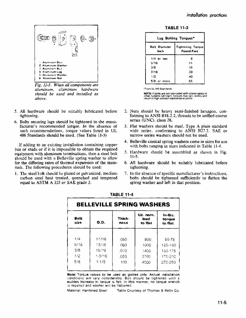

covered and insulated aluminum wire and cable
Fig 11-5 Belleville washer is used to make an aluminum-ta-copper or steel joint Note Crown of Belleshyville washer should be under the nut
With equipment having terminals that will accommoshy aluminum bolts and nuts are used only the heavy washer date only copper conductors a gutter splice may be bearing on the aluminum lug is necessary used to connect the aluminum conductor The aluminum Figures 11-7 to 11-12 show some typical connections conductor is spliced to a short length ofcopper conductor of aluminum conductors to equipment terminals and the copper conductor stub is then connected to the
Because of the differing rates of thermal expansion ofequipment terminal (Fig 11-4) An AL7CU or AL9CU aluminum and other conducting or support metals it is compression type connector is used to make the splice preferable to have all parts of the circuit including studs
Instead of a gutter splice onc of the many UL-listed and clamp bolts of aluminum The aluminum bolts should AL7CU or AL9CU adaptor fittings specifically designed be of alloy 2024-T4 and the nuts compatible though for this purpose may be used (Fig 11-6) preferably not of identical alloy and temper Bolts and
For connecting large aluminum conductors (500 kcmil nuts should be of heavy series design to reduce stress and up) to heavy equipment having copper terminal studs beneath the head NC (coarse) threads are preferred for andor pads large compression type lugs preferably with the 2024-T4 aluminum bolts Components should be two holes should be used in making such a connection assembled as shown in Fig 11-9 More information about (Fig 5-2) With other than aluminum bolts Belleville aluminum bolted connections will be found in Chapter spring washers and heavy flat washers in consecutive 13 arrangement as shOm in Fig 11-5 must be used If
Fig 11-7 Where possible current transformer terminals should be reshyplaced with compression type (B) If not possible 0 remove section of copper cable should be spliced to aluminum (AJ
Fig 11-8 Power transformer ter- minals ifcopper must employ short copper stub spliced to aluminum L___~~~~~=-_Jcable
Fig JI-4 Gutter splice is used when terminal lugs are not removable and are approved for copper cable connection only
~lO ~ t 2 3 fi5
Crown Facu ut
t Aluminum IY ~ BlI$ (or stud) 2 Sfe1l1 or CQPper St 3 AIminvM Lug 4 St~iJl Flat Washef 5 Steel Selleville 6 Sleel Nut
Fig 11-6 There are a number of UL-listed adaptor jittings available for use with terminals not suitable for direct connection of aluminum conductors
11-6
installation practices
Fig 11-9 When connecting alushyminum conductors to a unit subshystalion with copper bus use compression type aluminum lugs attached with a steel bolt a fiat washer and a Belleville washer (A) Copper primary leads on transshyformer are connected to aluminum feeders in aluminum connectors and bolted back-to-back using a steel bolt a fiat washer and a Belleville washer (B)
Basic Installation Techniques
Fig 11-10 Three methods of makshying motor connections are shown in detail A All terminals are prefshyerably aluminum Where bolt is steel or copper Belleville washer is necshyessary (B)
Fig 11-12 Copper lug connections on switchgear are repaced with equivalent aluminum connectors Belleville washer is used with copshyper or steel studs
1 Stripping Insulation
Never use a knife or pliers to ring a conductor when stripping insulation One way to avoid this is to pencil or whittle the insulation (Fig 11-13)
Another method is to skin the insulation back from the cut end of the conductor and then cut outward (Fig 11-14)
Several types of insulation stripper are available for quick easy removal of insulation One of these useful for small size conductors is shown in Fig 11-15
2 Making Connections
Preparation of aluminum conductors for connection to an equipment terminal or another conductor requires stripping of the insulation and rupture and dispersal of the nonconducting oxide film that appears quickly on a fresh aluminum surface exposed to air Care must be taken not to nick the wires when removing insulation in order to avoid broken strands in installation or service Seveltl types of insulation stripper are available for quick easy penciling or square-cut removal of insulation One type is shovn in Fig 11-16
Abrading the conductor strands with a wire brush or other appropriate tool will serve to clean the conductor
and disperse the oxide coating prior to application of joint compound
The conductor end is then inserted into a compression sleeve of adequate thickness or a suitable mechanical type pressure connector If the connector does not come factory-filled with an acceptable joint compound such paste should be applied to the conductor end before insertion into the connector (Some manufacturers conshynectors may not require the use of compound but it should be used in the absence of specific instructions to the contrary) The compression sleeve should then be compressed with a hydraulic compression device or the setscrew of a mechanical connector tightened in a manner prescribed by the connector manufacturer Excess comshypound should be removed from the conductor insulation but not from the joint itself where it will serve to prevent air from entering
Solid aluminum wires are prepared in a similar manner and the smaller sizes may be fastened under a bindingshyhead screw (without joint compound) after looping in a clockwise direction
Note The ALiCU or AL9CU marking is not required on equipment connectors However the equipment in which they are installed must indicate suitability for use with aluminum and connector tightening torques
11-7
covered and insulated aluminum wire and cable
Fig 11middot13 Never ring a cable-it may lead to a break Insulation should be removed as one would sharpen a pencil
Fig 11-14 Another safe way of removing insulation from conducshytor is to peel the insulation back and then cut outward
Fig 11-15 Use wire stripper for removing insulation from smaller wire sizes Match stripper notch to wire size
Fig 11-16 Penciling tool for removal of insulation in bevel configuration by rotation Several sizes are availshyable which by proper selection ofbushing are applicable to all usual sizes of cables This tool is particularly suitable for primary cables which have comparatively thick insulation
In making connections first strip the insulation as instructed heretofore Then apply joint compound if it is not already contained in the connector
If the connector is a mechanical screw type appJy the manufacturers recommended torque (Fig 11-17) In absence of specific torque recommendations use UL 468B torque values shown in Table II-I Ifacompression type crimp it as recommended by the manufacturer (Fig 11-18) Be sure to select the correct size die and close the tool completely for full compression Wipe off any excess compound Then tape the joint as instructed under Section BZ Or apply the inSUlating enclosure that comes with some types of connectors
3 Pulling Conductors in Conduit or Electrical Tubing
The following procedures are applicable to conduit of all types including aluminum
a Run a fish line through the conduit This may be done by attaching the line to a piston-type device which is propelled through the conduit by compressed air Another method is to push a round flexible speedometer type steel wire through the conduit Polyethylene fish tapes may be used for shorter runsshyup to about 100 feet
b Attach a clean-out brush to the fish line and behind it attach the pull line then pull both through the conduit by means of the fish line
c Attach the pull line to the conductor or conductors A basket grip over the insulation may be used for this purpose (Fig 11-19)
11-8
installation practices
Fig 11-18 Crimping tool must be fully closed Failure to close crimpshying 1001 will lead to an unsatisfacshytory and weak joint
Fig 11-17 Proper torque is imporshytant-over-tightening may sever the Fig 11-19 Basket grip wires Or break the filling undershytightening may lead to overheating and failure (See Table 11-2)
d Where conductors are pulled with a rope stagger j When conductor ends are prepared for pUlling be sUre the conductor ends and anchor in position with tape not to nick the stranded aluminum conductor during to provide maximum lIexibility around bends (Fig insulation removal Damaged strands can reduce the 11-20) pulling tension capabilities of the conductor To avoid
this pencil the insulation for removal as described above do not ring cut the insulation
k Follow all NEC requirements
Fora detailed description ofcalculating pulling tensions see the example given on page 11-11 on underground installations See Chapter 17 for a complete treatment of aluminum conductors in conduit
Fig 11-20 When a rope pull has to be used skin the cable ends and stagger them after locking with tape 4 Installation of Cables in Trays This will hold tie to a minimum Where aluminum cable is to be pulled in trays or cablecross section racks take the following precautions plus those applishy
cable to conduit e Try to feed conductors into conduit end closest to the a Where pulling attachments are used on the conductors
sharpest bend to reduce pulling tension cover them with rubber-like or plastic tapes to prevent pound Have pulling equipment with adequate power available scoring of the trays and installation sheaves during a
to make a steady pull on the cables without jerks conductor pull during the pulling operations b Use large-radius sheaves around bends and smaller
g Use pulling compound compatible with the conductor sheaves on the straight sections of cable support trays insulation as the conductors are fed into the conduit to facilitate cable installations to reduce the required to reduce coefficient of friction and required pulling pulling tensions and to prevent damage to stranded tension conductors or insulations
h For single conductors on a reel stagger reels one c Where cables are anchored on trays be sure straps behind the other while feeding in conduit to maintain or other cable anchoring devices do not cut into the equal pulling tensions and prevent conductors from insulation crossing over and jamming in the conduit d Cables installed in trays should follow the requireshy
I Wherever possible pull conductors in a downward ments of NEC Article 318 for the aUowable number direction to allow gravity to assist in pulling with of cables permitted in trays and their respective reduced tension ampacities
11middot9
covered and insulated aluminum wire and cable
e Straight cable tray runs may often be installed by simply laying thelightweight aluminum cables in place
f Be sure tray supports are capable of handling maxishymum weight of conductors and planned conductor additions in the future
5 Minimum Training Radii
Where permanent bends are made at terminations using aluminum building wire Table 11-5 indicates the minishymum bending radius as a multiple of the overall cable diameter Such bends should be made before the terminal is applied to minimize electrical contact distortion
6 Conductors in Vertical Raceways
The NEC under section 3()()19 stipulates that conducshytors in vertical raceways shall be supported As a general rule one cable support shall be provided at the top of the vertical raceway or as close to the top as is practical plus an additional support for each interval of spacing as shown in Table 11-6 An exception to this rule is that if the vertical riser is less than 25 of the spacing listed in the Table nO cable support shall be required
Installing Cable in Conduit or Duct
Theprocedures forinsertinga fish line or tape through a conduit or duct followed by a pull line andlor cable as required for the pull are well known and established as field practice and do not need extensive description here Aluminum conductors may be attached to pull line or cable by means of a factory-installed pulling eye by placing a basket grip around the conductors insulation (Fig 11-21) or by tying the line to a loop in the uninsulated part of the conductor (Fig 11-20) Steel pull cables used to pull conductors around bends in aluminum conduit runs may damage the conduit at the bend This is often avoided by using steel elbows with aluminum conduit or by use of a pull line that will not damage aluminum elbows
Pulls should be accomplished with steady tension and pulling speeds not exceeding 50 feet per minute Hard pulls can be eased if the reel if hand controlled and slack cable is guided into the conduit
Pulling tensions may be reduced by lubricating the cable surface However SOme lubricating materials have been found to adversely affect cable insulations or outer jackets In addition to cable pulling compounds this
TABLE 11-5 TRAINING RADII
For 600 V Cable Not in Conduit on Sheaves or While Under Tension
POWER CABLES WITHOUT METALLIC SHIELDING ON ARMOR The minimum recommended bending radii as muHiplies of 1I1e overall cable diameter given in the following tabulation are for both single and multi-conductor cable with or without lead sheath and without metallic shielding or armor
Minimum Training Radius Thickness of as multiple of cable diameter
Conductor Insulation Overall Diameter of CAble-Inches mils 1000 and Less 1001 to 2000 2001 and over
155 and less 4 5 6 170 to 310 5 6 7 325 and over 7 8 I
POWER CABLES WITH METALLIC SHIELDING OR ARMOR (a) Interlocked Armored Cables
The minimum recommended bending radius for all interlocked armored cables is in accordance with table above but not less than 7 times the overall diameter of the cable except as noted below (c) for tape shielded cable
(b) Flat Tape and Wire Armored Cables The minimum recommended bending radius for all flat tape armored and all wire armored cables is 12 times the overall diameter of cable
(c) Tape Chielded Cables For ali cables having metallic shielding tapes the minimum recommended bending radius is 12 times 1I1e overall diameter of the completed cable
(d) Wire Shielded Cables Wire Shielded Cables should have the same bending radius as power cables without metallic shielding tape Aepfilted loon ICEA 5-66-524 NpoundWA WC-7
11-10
instollation practices
TABLE 11-6
SUPPORTING CONDUCTORS IN VERTICAL RACEWAYS From 1987 NEe Table 300middot19 (a)
Conduelors
Aluminum Copper
No 18 to No B Not greater than 100 feet 100 feet
NO6 to No 0 Not greater than 200 feel 100 feel
No 00 to No 0000 Not greater than 180 feel 80 feet
2116 kernil to 350 kernil Not greater than 135 feet 60 feet
350 kernil to 500 kernil Not greater than 120 feet 50 feet
500 kernil to 750 kernil Not greater than 95 feet 40 feet
Above 750 kernil Not greater than 85 feet 35 feet
applies to potting and joint compounds adhesives tapes etc If in doubt compatibility of materials foreign to the insulation should be cleared through the cable manufacmiddot turer
A number of proprietary wire puUing lubricants and compounds are UL-listed and labeled to indicate the compounds compatibility with conductor coverings In all cases the manufacturers instructions should be obmiddot served
Allowable Pulling Tension
The following formulas can be used to calculate the maximum allowable tension that should be applied to the cables Note that these allowable tensions assume the pullshying eye is attached to the conductor Where the pulling line is attached to a basket grip that surrounds the insulation the pulling tension should not exceed 1000 100 It should be kept in mind that tension developed for straight runs per unit length is less than that for the portion of the cable in bends
L The maximum aJ~owable pulling tension if the pulling eye is aHached to the conductor
(Eq Hmiddotl)
where Pm Maximum allowable tension lb N Number of conductors being pulled simultaneously A Circular mil area of each conductor
(If conductors are of various sizes add the individshyual NA values)
K = Conductor stress factor
2 The maximum allowable pulling tension (Pm) cannot exceed 1000 Ib where cables are pulled with a basket grip however the tension per Eqs 11-1 or 1t-2 should nOL be exceeded
3 The matimum allowable pulling tension for cable in conduit
or duct bends (to prevent cable damage becallse of rubbing on sides of bend) must not exceed the following
Ib = 100 r (Eq Hmiddot2)
where Ptgt = Maximum allowable bend tension Ib r = Radius of curvature of the conduit or duct bend ft
Note The maximum aIIowable tension determined from Eqs 11-1 or 1l~2 should not be exceeded
4 For straight section of conduit or duct the pulling tension (lb) likely to be developed can be determined as follows
P=L w t (Eq Hmiddot3)
where p~ = Pulling tension in straight section Ib L Length of conduit or duct straight section ft 1 = Weight of cable (or cables) lb per ft t = Coefficient of friction
Note For a wen constructed conduit or duct with a lubricated cable f approximates 05 For less favorable conditions or with considerable curvature f may approximate 075
5 For curved sections of conduit or duct the pulling tension (lb) likely to be developed can be determined as follows
Ic =1 + 1 eta CEq 1l-4) where Pc = Total pulling tension Ib
Ps = Tension for straight section at pulling end Ib PI = Tension for straight section at feeding end Ib = Angle of bend in radians (I radian = 573 deg) e = Base of Naperian logarithms (2718) f = Coefficient of friction
Example Determine the maximum pulling tension required to install three single-conductor cables in a duct according to the arrangement in Fig 11-22 The cable specifications are
Three single conductor 40 AWG 600-volt aluminum cables with cross-linked PE insulation
Weight 3 290 IbM It = 087 Ib per ft Cable diameter each 0690 in
Coefficietlt of friction=O5 K valueQOOSshy
middotK 0008 for ~ hard aluminum conductors or 0004 for Y2 or J4II
hard aluminum
iIgtiFfR ~o 5 11-11
covered and insulated aluminum wire and cable
A Condttj~ or Doct Ckan)Ot Brush
B Kellems Grip
C Job Famianed Pulling BlUket
Fig 11middot21 Pulling cable in duct Pulling cable between junction boxes of conduit installations is similar
Using a single pulling eye attached to the three conductors and applyshying Eq 11~1 the maximum allowable pulling tension is
Pm=0008 X 3 X 211600=5078 Ib per Sq IImiddot I For the entire run from pull-box (I) to pull box (6) the tension
increments are as follows Sq
11middot3 At box (2) p == L X w X t == 100 X 087 X 05 == 435 Ib
f 0 05 X 1S71 11-4 At box (3) p == P X e = 435 X e
435 x 2194=954
11middot3 At box (4) P = 954 + (4 X w X tJ == 954 + (SO X 087 X 05) = )J72 Ib
0$ X 1571 114 At box (5) p == 1172 bull = 1172 X 2194 =
257llb
11middot3 At box (6) P 2571 + (4 X w X f) = 2571 + (15 X 087 X 05) = 2637 Ib
The total puning tension of 254 lb is far below the 5080 Ib limitation and the tension at each bend is far below the
11-12
recommendation per Eq 11-2 of 100 x 10 or 1000 lb Study of such examples shows that there is an advantage in puning cables from the pull box or manhole closest to the first bend This aids in reducing tension on the installed cable In this instance if the pull started at box (6) the final tension would be about half the above-found value
For a more complete treatment of cable puning in conshyduit the reader is referred to RC Rifenberg AlEE Tranmiddot sactions Dec 1953
Installing Directly Buried Power Cables
If cable placement can be started Defore sidewalks and other obstructions are installed the plowing-in method usually is the most economical method of burying power cable If soil conditions are unsuitable for plowing the
See also Aluminum Underground Distribution Reference Book
PULL BOX
50
PULL BOX
Fig 11-22 Diagram ocircuit layout to illustrate method of computing pulling tension
use of trenchers back hoes Or manual digging is custoshymary If the soil is rocky it should be screened to prevent cable damage Int is not sufficiently fine to closely cover the cable surface a four-inch thickness of sandy loam placed under and over the cable will improve the heat radiating quality of the soil
Duct Or conduit also should be used under streets or where access by digging to a buried cable is not practicable
Sufficient cable slack should be provided at risers and terminals to permit earth movement that may occur because of conductor thermal expansion frost and also as an allowance for future repair
Boards or slabs placed over the cable for mechanical protection should not be directly in contact with the cable but should be laid on an earth fill over the cable
Depth of burial ranges from about 30 to 48 inches for primary cable and from about 24 to 42 inches for secshyondary cable when buried separately On many systems both primary and secondary cables are buried in the same trench with no separation In many areas the trenches are shared jointly with other utilities notably communishycations-both telephone and television cables Joint use of trenches requires close collaboration on installation schedules but offers substantial economies to the sharing utilities
Initially a separation of one foot was required between primary power and communication cables and many comshypanies still require this separation An amendment to the NESC however permits random-lay (no deliberate separation) installation of communication and power cables in the same trenches with grounded wye power systems operating at voltages not in excess of 22 leV to
installation practices
ground ordelta systems operating at voltages not in excess of 53 kV phase to phase under certain conditions describshyed in NESC Section 35 Article 354 However joint use with very long single-phase primary circuits is not recomshymended because of the inductive pickUp of harmonics by the communication cables from the power cables
Care exercised in handling the cable during installation will help to avoid trouble later for damage sustained by the cable during installation has proved to be a major cause of subsequent cable failure
Many of these precautions have to do with making sure there is no insulation damage The cable is not susceptible to corrosion failure when insulation is unbroken even where moisture has gained entry into the conductor is some manner this fact has been determined in cable manufacshyturer laboratory tests and from research by utilities Migrashytion of moisture through damaged insulation in the presence of ac potential concentrates ions and promotes ac electrolysis
Cable transitions between overhead and underground usually employ the conventional factory-molded pothead of which special types are available for use in URD systems A termination is not reqnired however if the insulated aerial cable is also suitable for direct burial Such a cable can be carried directly down the pole Riser shields or conduit should be used to protect the cable on the riser pole to a point at least eight feet above ground level and should extend at least 12 inches below ground The riser shield must be solidly grounded to the system neutral and bonded to the lightning arrester to avoid transient potentials
Many other practices relating to buried cables and their connection to transformers to service entrances and tap connections in junction boxes and vaults are described in industry manuals Practice is gradually becoming standshyardized in the direction of increasing reliability and lowershying installation and maintenance costs in this most imshyportant segment of power distribution
The following suggestions will help to avoid failures from this cause they apply equally to cable and cable in pipe
1 Make sure that end seals are intact both while the cable is stored and installed to avoid entrance of water into the strands
2 If plowing is not used cables if at all possible should be payed out along the side of the trench from moving reels or carefully laid in the trench from stationary reels
3 The trench should not be dug before final grading is determined so cable will not be exposed or be too close to the surface
bull See also IEEE Conference Record 31C35 Special Technical Conference on Underground Distribution Sept 27~29 1966
11-13
covered and insulated aluminum wire and cable
TABLE 11middot7
I ICEA MINIMUM BENDING RADII FOR POWER CABLES
WlTHOtIT METAlliC SHIELDINGmiddot
I Minimum Bendine RHii as a Multiple of Cable Diameter
I cabl DO Inchbullbull
Tlllcimess of 1000 1001 2001 i
Insulation Inch I and less tD 2000 and OYer
0156 and Ie 4 5 6
I 0157 to 0312 5
i 6
7 0313 and over - 7 S
bull Only applicable for cable training bearing pressure limitation may require larger bending radii for cable tension
Data apply to single and multiple conductor cable also to wire-shielded cable Minimum bending radius for cables with metallic shielding tape is 12 Urnes the completed cable 00 The National Elecshytrical Code Section 300-34 requires 8 times fot non-Shielded and 12 times for shielded medium voltage cable bending radiI
4 In rocky soil areas use screened backfill Or sand to protect direct buried cable A 2-inch bedding is sufficient below but there should be a minimum cover of about 4 inches (The bedding and cover can be omitted when duct in conduit is used)
5 If boards concrete slabs etc are used above the cable for mechanical protection they should not be in direct contact to avoid shearing action when the soil settles Make sure boards are treated with preshyservatives that will not harm the cables insulation
6 Check the cable visually for damage before burial or installation in duct
7 When primaries are pulled into ducts or open trenches the use of a pulling grip over the cable is common rather than a pulling eye or other attachment conshynected directly to the conductor Duct should be carefully cleaned by pulling a plug through it to remove all burrs and obstructions To keep the cableshypulling tension within safe limits a lubricant approved for use with the specific insulation and insulation shield should be used
8 When doing permanent training make sure that the minimum bending radii are observed (see Table 11-7) Make every effort to provide more radius than these values at reel payout risers plow guides duct bend etc
9 Make sure splices and other connections are made in accordance with manufacturers recommendashytions
10 Double check to make sure proper backfilling is done Rock fill should be kept away from the cables to
prevent damage Compacting should be carefully done and air spaces minimized
11 Proof test the cable after installation to insure integshyrity of insulation and splices (See Table 11-8)
12 Dont overfuse the cable Because of the paucity of failures many utilities prefer to use one-shot fuses as an added protective measure for the cable
Many of these precautions have to do with making sure there is nO insulation damage The conductor in 600 volt cables is not susceptible to corrosion failure when insulation is unbroken and moisture has not gained entry into the conductor When moisture enters a break in insulation however ac electrolysis begins
Splicing and Terminating in Underground Systems
The revolution in underground distribution system design has included the devices and methods used for making splices connections and terminations The obshyjective here has been to reduce the amount of skill and time required in the field so as to reduce the installation costs More prefabrication is being done under factoryshycontrolled conditions and the need for heating and pouring of insulating compounds or extensive taping in the field has been greatly reduced
Aluminum connectors and terminating devices should be used with aluminum conductors so as to avoid differshyential thermal expansion and contraction upon heating and cooling that could result from the use of connectors of dissimilar metals Compression type connectors and lugs applied with a tool and die are widely used It is
11-14
instolation practices
TABLE 11middot8
ICEA RECOMMENDED de PRooFmiddotTEST VOLTAGES (15 Minute Test)
Polyethylene or CrossmiddotLinked Polyethylene Insulatd cables
ProofmiddotTestRated Insulation Voltage 1mCircuit Thicllnm (Mils)Voltage Installation
i
25 5001middot 8000 115 2001middot 5000 90
35 8001middot15000 175 55
15001 middot25000 80 25001 middot28000
260 85280
28001middot 35000 345 100
important in installing these devices that a die of the correct size be used and full pressure be applied in order to obtain permanently sound connections
600 Voll Secondary Clrcuils
In this regard connector manufacturers have made important advances in the design of connection devices for secondary circuits There are far too many types to describe them all in this handbook However a couple of examples are given below to indicate the types of premiddot molded splices and terminations that are currently availmiddot able for this type of service
(a) Underground Direct Burial Splice 600 volt insulated cable splices are available for conductor sizes 6 AWG stranded through 1000 kcmil and can be completely installed and sealed without taping or compound filling Typical installation procedure is (Fig 11middot23) as follows
Step A
Lubricate both insulating splice caps by applying a small amount of the supplied lubricant to the inside diameter of the cap at both the housing end and also to the inside diameter at the conductor hole end For easier assembly of the insulating caps to the conshyductor jt is recommended that the insulation at the end of the conductor be penciled before stripping Then place the proper caps over each conductor end
Step B
Strip correct length of conductor insulation for the splice connector being used Place splice housing over end of conductor and assemble one cap to housing Large end of cap should cover the knurled line of the housing body
Step C
Wire brush exposed cable ends and then immediately
insert cables into connector Start crimping splice onto conductor as per manufacturers instructions Continue crimping to ends of splice overlapping crimps 118 inch minimum Wipe away all excess oxide inhibitor
Step D Place housing with the assembled cap over splice connection and snap remaining cap in place on housing to complete the sealed splice When caps are correctly installed the large ends should cover the knurled lines on both ends of the housing body
(b) Secondary 600 V Underground Terminations There are several different designs of connector products which are approved for use in underground 600 V electric power systems They supply the needs of connectors required for residential or commercial use direct burial below grade vaults pedestal or pad mounted equipment bolted or compression fittings and in any combination
Fig 11-24 shows a representative group of these fittings which are designed to accommodate a wide range of conductors Their installation is straightforward and reshyquires no field cutting or hand taping for insulation or environmental sealing The threaded stud connector for transformers is such that the connector can be detached from the transformer without disconnecting the conducmiddot tors
Primary Circuits
Termination of primary underground cables requires some type of stress relief Initially these were made up by taping a stress cone which proved to be one of the most tedious and time-consuming jobs for the field man Today most utilities use some form of preshaped Or prefabricated stress cone which can be installed in a fraction of the time
11-15
-----------
covered and insulated aluminum wire and coble
B IN4fyenSUIATlNGCAP rNO PENCILING
__ bull ( REQUIRED
- -f -- -~I L
c - ~ _shy
D
STRIP os lENGTH
INSUATINi CAP KNURLED LINES
- - - - -HHH+shy~ SPUCE HOUSING
~~~-~~~-$PUCE CONNECTOR INSULATING CAP bull----- E--- KNURLEO
LINES
l__________________________________________________________~c~ou_n_e~~8~la~Ok~b_ria~n~C~O~_J Fig 11middot23 Secondary 600 V Underground Splice Kit showing sequence of assembly steps
Typical terminations for primary cables indicate that molded precut tape and porcelain types are used indoors while porcelain units are most often used outdoors One of the most significant developments in primary cable terminations has been the introduction of plugmiddotin conmiddot nectors for joining the cables to equipment or other cables With these devices it is almost as easy to conncct a primary cable as to plug in or remove an appliance cord from a convenience outlet
11middot16
The concept of premolded stress relief takes the fabshyrication of a stress relief COre away from the field and into the factory with its controlled environment leaving just the assembly to the field installer Elastomeric conshynections form a very convenient inexpensive and reliable method of connecting or terminating high voltage cables Power cable loadbreak elbows in the 35 kV class were introduced to the industry in 1983 with designs for 15 kV and 25 kV following in 1985
installation practices
CAP for porcelain bushings
Set screw s In seu connector are light shyened dow n on flat side 01 Adapter pressure deforms Adapter to lock Ad~pter and seu conneCtor to threaded stud un screws can be b8 C k~d -ofl Adapter and seu conn eCt or removed from transformer without remo ving conductor from connector
Thr eaded Stud Secondary Bush ing
l Adapter Scr6W5 on threaded tud of bllshing Iat side 01 Adapter mUSt be oriented to receive sel Ic rews
seu connector slips o ver Ad apUlr All Adapters have ~
0-ring5 In Sealing Cep same 0 0 all seu con shyseal arond Bushing neclors ho ve seme Adepter Neck and seu connector cavit y 10
Fig -24 Some typical 600 V underground termination fillings
Through the combined efforts of the connector and Some typical applications of premolded products are apparatus manufacturers and the utilities there is availshy at pulling or junction boxes cable to equipment connecshyabte today an array of premolded products that exhibit a tons and cable to cable connections All of these comshyhigh degree of safety reliability and flexibility ponents are designed and tested to be in compliance with
ANSUIEEE Standard 386-1985 Separable Insulated middotSee James W Fitzhughs paper Exploring the Application of Connectors for Power Distribution Systems above 600 Premolded Products for High Voltage Power Systems Volts
11-17
covered and insulated aluminum WIre and cable
Prlo(o counesy 01 ELASTIMQLO
Fig -25 Power cable joint for use af 15 k V or 25 kV
Primal( Voltage Circuits
A cutaway view of an up-to-date power cable j0i nt is shown in Fig 11-25 The cloverleaf design allows the joint to operate at lower temperatures
While installation of premolded devices are si milar conditions may vary depending on the device the cable and the manufacturer of the splice or termination In all cases full instructions will be provided and should be followed Additional typical designs are shown in Fig 11-26
Development work in splicing connecting and tershymina ting devices is still proceeding Users thus are ad vised to keep posted on the latest designs being offered by the connector manufacturers in order to achieve greatest economies in making cable splices connections a nd terminations
Though recent trends have been toward the use of premolded splicing and terminating devices it is still necessary or desirable in some circumstances to make hand-taped joints by traditional methods Because of this the details of making a hand-taped concentric neutral st raight splice are given below Details of the joint are shown in Fig 11 -27
The following are the in struction s to be generally based in making the joint illustrated in Fig 11-27 They are for a typical hand-taped primary cable splice All splices and terminations should be made by a qualified cable splicer in accordance with the manufacturers instructions and recommendations
I Study splice drawing and instructions
2 Train cables into final position and overlap for 18 inches to afford enough excess concentric wire for final jointing
11-18
3 Tem porarily wrap a number of turn s of tape over the outer concentric wires at least 18 inches from the centerline of the splice
4 Carefully unwrap outer concent ric wires and temshyporarily remove them out of the splice area being sure not to damage or kink them
TABLE -9 Recommending Taping Dimensions
Inlull-Ok A B C 0 K
Thkkmiddot u
15KV
175P One- Iall
Connector Zmiddot 4 2A oj- 14~ 38 220 lenglh
25KV
One-tlall 2so Connecl0r 2W 514 2A + 1112 716
length
35KV
One-hall 916~345 7Connector 2A + 22
length 5 Cut off excess cable at splice centerine
6 Remove outer semiconducting jacket for a di stance of (A + I + B + C) inches from each cable making sure th~t the insulation is not damaged during the removal operation All traces of the semiconducting jacket must be removed by a nonconductive abrasive or rasp
7 Remove the insulation from each conductor for a distance of (A + I) inches making sure that the conductor is not nicked during the removal operation
installation practices
Assembly of Tee Splice and Tap Devices
bull Straight Line Splice
Disconnectible Straight Line Splice
Loadbreak Elbow
Connectors
Modular Cable Terminator
Fig 11-26 Some typical primary voltage premolded splicing and terminating devices
11-19
covered and insulated aluminum wire and cable
Splicing-15kV-25kV-35kV Primary Cables-Hand Taped Splice Single conductor with concentriC neutral straight splice (conventional or crossmiddotlinked polyethylene insulated solid or stranded) for grounded neutral service
Concentric Wires TwiSled amp Spliced in Connector
One Hlfmiddotlapped Laye Friction Tape Halfmiddotlapped layer SemlmiddotConducting SelfmiddotFusing Tape
Self-Vulcanizing Tape One Halfmiddotlapped layer 10 K Thickn Tinned Copper Mesh Braid
Two Half-Lapped layers Self-Fusing middotA = OnemiddotHalf Connector lengthRubber-Like Tape
Fig 11middot27 Details ofa taped primary cable joint
Penciling tools will remove the insulation as well as provide smooth penciled surface
8 Apply the required compression connector on each cable following the connector manufacturers recmiddot ommended procedure Note It is recommended that a smooth surface type connector be used--not an indented type If an indented type is used fill the indents with a pliable insulation putty
9 Remove all sharp edges from compressed connector using a file Or heavy abrasive cloth
10 Pencil the ends of the polyethylene insulation for a distance of (B) inches Be sure not to cut into the insulation or damage the conductor during the penshyciling procedure Buff the insulation pencils if they are not smooth with a nonconductive abrasive or rasp This step would be completed with a penciling tool (See Step 7 above)
II Clean all exposed surfaces with a nontoxic and nonflammable solvent and allow to dry Care must be taken in wiping the black conductingjackets since this may smear over the insulation surface
12 Apply one half-lapped layer of semiconducting tape (Bishop Tape No 17 or equivalent) over the exposed conductor and connector Tape should just contact the edge of the cable insulation and be applied with enough tension to conform to the connector
13 Apply halflapped layer of high voltage selfmiddotfusing tape with manufacturers recommended tension starting at connector centerline and building up to the level of be connector in areas between insulation pencil and connector by evenly wrapping tape back and forth across the connector Apply splice tape buildup to a thickness of K inches over the connector and for a longitudinal distance of D inches tapering at the ends
14 Apply one hulf-Iapped layer of selfmiddotfusing semiconshyducting tape over insulating tape buildup extending I inch beyond insulating tape onto be semiconducting jacket on each side of splice The semiconducting tape should be applied with adequate tension
15 Apply one half-lapped layer of tinned copper mesh braid over the semiconducting tape and extend I inch at each end of splice The tinned copper mesh braid
11-20
Insulating Tope
Fflction Tape
Rain Shield
r-h~bj--Insulaling Tope
Melol Grounding Strap
installation practices
should be wrapped as tight as possible and taping should be started at the centerline of tbe splice using two portions of tinned copper mesh braid
16 Apply two solder lines 180 degrees apart for the full length of the mesh braid making sure that the heat does not remian in one spot too long to damage the cable insulation or tapes
17 Tie the concentric outer wires in place using wraps of No 14 AWG tinned or bare copper wire and tack solder in place
18 Apply two half-lapped layers of a self-fusing high voltage tape OVer the outer braid with minimum tension
19 Apply one half-lapped layer of jacket tape over tbe mesb braid to the edge of the concentric wires at each end of the splice
20 Twist the concentric wires together and cut off excess length Place the formed wires into the proper sized mechanical (or compression) connector and splice in place to form low resistance joint following the connector manufacturers recommended procedure
o Insuloling Tope --IO~
Conduclor --+0
Coble Insulolion --1~
Insuloling Tope
Friclion Tope
Rain S~ield
Bios-Cui I nsuloting Tope
Mesh Shielding Braid
Friction Tope
1t1--Stress-Re lie Cone
Coble Shielding Tope --Hic1--J
Jacket
A Single conductor outdoor termination
Terminal Lug
Mesh Shielding Braid
+----Jackel
B 3-Conductor outdoor termination
Terminating Detail
The construction details of secondary or primary cable terminations depend on whether the termination is outshydoor indoor or from underground and wbether it is horizontal for connection to an equipment terminal or vershytical for connection to another conductor Trifurcating assemblies are also used for terminating a three-conductor cable so the urunsulated terminals are well separated (Fig 11-28)
Terminations usually are either of the pothead type or the built-up stress-relief type Both types provide extra insulation close to the actual termination ofthe conductor to provide protection against the extra voltage at these locations
Primarily potheads of plastic insulating materials are used with primary and secondary URD systems altbough porcelain potheads and semi-assembled built-ut sess relief cones (or kits that facilitate tbeir qllick assemt) _e still used for this application (Fig ll-16)
Stress-relief cones are also required in cable splices
Terminal Lug o o
Ilir--Conductor It-lt-Insulang Tope
Fig 11-28 Typical terminations S-lSkV
11-21
covered and insulated aluminum WIre and cable
where there is a change of conductor size the variation of current density in the adjacent conductors creates dielectric stress variations that occur when a cable is terminated
The detailed methods of terminating shielded and nonshyshielded cables closely resemble those used for splicing except that the termination process requires the inclusion of a stress-relief cone or a pothead and if the installation is outdoor and vertical the addition of a rain shield to shed water from the cable insulation is customary Descriptive details are supplied by cable and accessory manufacturers with dimensions for various sizes and voltages The accomshypanying illustrations list the successive operations The precautionary recommendations mentioned in relation to cable splicing also apply to terminating procedure subject
1 TERMINAL CONNECTOR The universal rod connector attaches to the power source
2 MOLDED RUBBER CAP Presses over top of tenninator with an intershyference fit to provide complete wsterseal in~ tegrity
3 RETAINING WASHER Mechanically prevents any cable slippage within terminator
4 TERMINATOR HOUSING Molded of special EPDM compounds lor funcshytional reliability and long life Actual creep distance is 18 (457 em)
5 CABLE INSULATION Primary insulation is provided since cable insulation carries through the terminator
6 INTERFERENCE FIT Molded insulating EPDM exerts unffonn conshycentric pressure on insulation of cable to provide required creepmiddotpatl1 length and washyterseat
7 MOLDED STRESS RELIEF Factory-tested molded stress relief assures proper stress relief for terminating cable A patented Elastimold feature
8 GROUND STRAP Provides a convenient point to connet a ground wire to the molded conductive shield and places the molded shield at ground potential
Courtesy Amerace Corp Elastimold Div
to such changes as appear in manufacturers instructional manuals
The cross-section of a molded terminal connector is shown in Fig 11-29 illustrating the component part ofa connector designed for conductors up to 25 kV It is suitable for uSe on solid dielectric cables and can be applied directly on cables with extruded semi-conductive shields including full neutral concentric It will accomshymodate aluminum conductors in the range of No 6 to 410 AWG with an insulation thickness of 0495 to 1115 Mter proper cable preparation the terminal connector is slid down over the bared cable insulation until it bottoms On the cable shield No special tools or potting compounds are required for the assembly of this type of fitting
Fig 11-29 Typical single conductor molded pothead for cable termination
11-22
Installing Aerial Insulated Cables
Single insulated or covered overhead primary aluminum conductors suspended from insulators sometimes are used in tree areas or similar locations Their installation is simishylar to that of bare conductors as described in Chapter 5 The span lengths usually are moderate so that sag and tension values generally are obtained from tables Howshyever for unusual spans sag-tension charts can be comshyputed or are available from conductor suppliers For aluminum 1350 conductors or less than hard tempers adjustment must be made for reduction of strength
For economic reasons however most overhead spans of insulated power conductors are in the form of preasshysembled or field-assembled multi-conductor cables susshypended from a bare messenger Insulator support is not required and space is saved by using a single-multi-conshyductor cable The conductors may be spiraled around the messenger or arranged paraliel to it as described 10
Chapter 7 Messenger supported cables are in two groups
Preassembled aerial cables (to 35 kV) Aerial cable assemblies (0 to 600 volts)
Primary Aerial Cables
The messenger size for primary cables is determined by the required strength except that for single-phase prishymary circuits (No 2 A WG or smaller) where the messhysenger also serves as a neutral conductor the conductance of the messenger must equal that of the insulated conshyductor Bare messengers not used as neutral conductors are often used also as a part of relaying circuits as a part of the grounding circuit for the insulation shielding and as an auxiliary to a common-neutral For these reasons specifications for multi-conductor primary cables with bare messengers usually specify the ohmic resistance of the messenger The combination of strength and moderate electrical resistance requirements of such non-neutral messhysengers has led to wide acceptance of composites of aluminum and of steel (Alumoweld) for the make-up of the messenger
Messenger sizes are such that the normal initial sagging tension at 60F will not exceed 30 of its rated strength and its maximum tension will not exceed 50 of its rated strength at the fully loaded condition Physical details of the cables used for the messengers listed in Tables 11-10 and II-II can be found in Tables 4-5 (1350-Hl9) 4-12 (6201-T81) and 4-14 (ACSR) These messenger sizes conform to the ICBA recommendation that the initial sag be such that the final sag be not less than 1667 of the span length
Stringing sag and tension charts are supplied by cable manufacturers as an aid to circuit design for light medium or heavy loading conditions (NESC see Table 5-1) for use as described in Chapter 5 However in most instances the spans are of moderate length so suitable sag-tension values may be obtained directly or interpolated from manushy
installation practices
faeturer-supplied tables that Jist initial and final values for 100 125 and 150 ft spans
For the installer of the cable the most useful tabular values are those for initial sag and tension usually for 60degF but a correction factor is applied if the installation temperature differs from 60F The final sag and tension values for the various NESC loading districts then will meet requirements as to the percent that messenger tension bears to its ultimate breaking strength and the manufacshyturers table will confirm this if required The messengers for preassembled primary cables are not neutral conducshytors but high conductance is useful for grounding or signal purposes hence the equivalent conductor rating is usually listed for the messenger For this reason various combinashytions of steel 1350 aluminum and high-strength alloy aluminum are often used for primary aerial messengers
Table 11-10 is extracted from more complete tables in order to show the form in which such tables are supplied Although this table shows use of a combination messenger made of 1350 aluminum strands assembled with strands of aluminum-clad steel other messengers are similarly used of high strength ACSR as well as combinations of 6201 aluminum with steel reinforcement (AACSR)
Fig 11-30 depicts several kinds of fittings and accesshysories used when installing messengers and preassembled aerial cables some of which also apply to preassembled secondary and service-drop cables
Neutral-Supported Secondary and Service-Drop Cables
Preassembled aluminum insulated multi-conductor cables supported by bare neutral messenger conductors have practically become standard for secondary aerial cirshycuits and service drops Subject to the NEC limitation of 300 volts to ground for bare neutrals the triplex form (two insulated conductors preassembled with a bare neushytral) supplies the usual single-phase three-wire circuits Similar quadruplex cables (three insulated conductors) if conneeted to a three-phase Y source supplies low-voltage three-phase loads
The neutral messengers of such cables are selected on basis of strength and conductivity either with conducshytivity equal to that ofa phase conductor or as a reduced neutral having conductivity not less than one-half that of a phase conductor depending on service requirements Tables in Chapter 4 show as mentioned above data regarding bare neutral messengers for such cables Chapshyter 10 describes various types ofcables Fig 11-31 depicts installation details for usual conditions of installation of the secondary cable and the service-drop taps extending from it Initial sag-and-tension data for preassembled triplex aluminum cables with full- and reduced-size neushytrals are in Table 11-11 for the various NESC loadings for 125 ft spans
11-23
3 Bolt Guy Clamp
2 Bott Unieurorsal GUY CHp
Split Bolt Connector
covered and insulated aluminum wire and cable
3 Bolt GUY Clamp
Oval Eye Bolt
Vise Type Connectors
The notation on Table 1I-1I with regard to initial sag values for other spans than 125 ft is based on Eq 5-2 but it is only approximate hence it is available to obtain correct values from the cable manufacturer
The sag-tension values of Table 11-11 are for initial unshyloaded conditions at 60F The sag eventually will inshycrease to the final value and the tension correspondingly will decrease as a result of long-time creep When fully loaded according to NESC values the sag and tension both will increase and as temperature drops to OCF under Heavy-Loading conditions the sag decreases and tension
F
2 Bolt Universal GUY Clip
B
E
Strand Connector
increase~ Thus for 20-20 cable with aluminum-alloy 6201 me nger the initial stringing sag-tension of 13 inshy865 Ib becomes 24 in-1955 Ib (see Chapter 5)
The sag-tension values under conditions of maximum NESC loading are useful for circuit design because they indicate minimum clearances under the cable and also verify that there is the specified margin between actual tension and the rated breaking strength of the messenger However tables imilar to Table H-ll for initial stringing conditions are us~d as a basis for installation which is the subject considered in this chapter
o
c
Fig 11-30 Typical details for supporting and dead-ending cables messengers and guy wires on poles
11-24
installation praclices
A
Prelcftllel
~ A V vv
Insulated Clevs
ToPIt
o
DeltldEno tor EQuol)
1 I
B
I Messger Suspesion CImp
Connector (Before Tpig)
c
Plastic Guard Plastic Guard
Messenger Suspension
Clomp
Fig 11-31 Typical installation details for secondary triplex cables neutral-messenger-supported showing service-drop taps and other details
A-Dead-end at pole shuwing also application of serviceshydrop span clamp
B-Double service-drop taps at service-drop span clamp and messenger suspension clamp at pole
C--Service-drop T tap near pole
Tope or Clip
C(lmp(e$$iO_~h~~Connettor_
I I I Prefarmed Oeoo~End (or EquOI )
D-Clevis support at pole for directional change of less than 45deg
E-Dead-end support at pole for directional change of mOre than 45deg
Notes Compression connections are to be taped even though not so shuwn Poles are to be suitably guyed to resist unbalanced forces Armor rods are used where abraSion is likely See Chapter 5 for additional details of armor rods and the like
11-25
covered and insulated aluminum wire and cable
TABLE 11-10
Representative Values extracted from Tables Supplied by
Cable Manufacturer for Initial Sag-and-Tension Values at
60F suitable for Light or Heavy NESC Districtgt
For Preassembled Primary AerialSmiddotIC Cables with AWAC Messenger
Conductor I Calgtl Span Length in FeetI ISize AWG or Kcmi
I
Messe
ISize
nger
Rated Strength
Assembly (2) Diam
in Weight 100 125 150 Ibltt Satinches (3)
100 i 125 I 150 Tensionmiddotlb (11
5000 Volt Unshielded (Class B concentric stranded aluminum cross-linked polyethylene insulation)
6 3-34 1
20 40 350 500 3middot25 750 2middot215
1000 10-25
UbI 7700
11300 13500 19500
1251 0421 19
1575 1770 2007 2374 2693 3215 3695
0645 I 0827 1100 19 1600 2158 3076 4053
23
23
28 337 428 509 516 780655
662 840 1000 27 1118 1364880
1280 1626 1983 21931726 2675
2461 i 3126 3813 3242 I 4119 5024
15()(J( Volt Shielded Grounded Neutral (Class B concentric stranded aluminum semi-con tape strand shield 0175 in XLPE insulation extruded semimiddotcon PE No 22 AWG copper concentric Mylar tape PVC jacket)
2 3-34 110 40 3middot25 350 10-215 500 750 55650()j307)
1000
7700
11300 19500
26900
2459 1379 19 2618 1606 3006 2215 3504 3075
3789 3696
4575 5039 5_079 6390
23 27
28
27
28
31
1122 11418 1739 1306 1645 2024
1801 2269 2679
2500 3151 3720 3005 3787 4659
4032 5040 6048
5031 J64()()~ 1 Initial tension lS such that the final temiion will not exceed 25 percent of rated strength at 60degF I for
light or Heavy NESC loading districts 2 Includes weight of messenger and binder tape
3 Initial sag is such that final sag approximately conforms to ICEA recommendation of 1667 percent of span length
11-26
instollation practices
TABLE 11-11
Typical Initial Stringing Sag and Tension Values for
Three-Conductor Sell-Supported Polyethylene Service-Drop and
Secondary Cable (Triplexl lor 125 ft span at 60degF
lor Various NESC Loading Districts (see Table 5-1
Note For roughly approximate value for spans of 100 ft and 150 ft multiply the initial sag values for 125 ft span by 064 for l00ft
span and by 145 for 150-ft span retaining the initial tension values for 125 ft span These approximations are less accurate for
the Heavy Loading District More accu rate values for spans other than for 125 ft are obtainable from cable manufacturer
I Neutral
Messenger I NESC Light-Loading
NiSC Medium-Loading
NESC
Heavy-loading Con- I Oistrict District District
ductor Size Rated Size AWG Initial Inital Initial Initial Initial InitialStrellgth r
AWG (or EquivJ Ib Sag Tension Sag Tension Sag Tension
ALUMINUM ALLOY 6201 NEUTRAL MESSENGER
4
2 10
20
4 2
IO 20
1760 2800 4460 5390
8 8 8 8
467 750
1195 1415
10 10 8
10
410 680
1060 1255
16 12 1 I
13
250 553 875 865
ACSR NEUTRAL MESSENGER
6 1190 10 2906 10 305 4 18604 10 445 8 415 2 2 11 5752850 10 660
4380IO10 10 1005 12 865 20 531020 10 1255 12 1070
REDUCED ACSR NEUTRAL MESSENGER
12 350 2 4 6 1190 12 295
4 13 445 13 435 110 2
1860 2850 13 670 14 600
20 3550 13 835 16 730I I ALUMINUM NEUTRAL MESSENGER (Aluminum 1350)
54 44
19 195 19 295 23 410
6 6 560 4 4 881 2 2 1350
10 110 1990
26 91 19 195 17 385 19 485
29 98 11 375 1 I 600 12 840 13 975
34 17 13 14
104 72 49 40
105 330 655 755
23 53
115 230
These jnitial sag-tension values are based on NESC loading limits for REA systems that is loaded tension is not to exceed 5000 of messenger rated strength final stringing tension is not to exceed 251 Of rated strength and initial stringing tension is not to exceed 33~13 Of rated strength
11-27
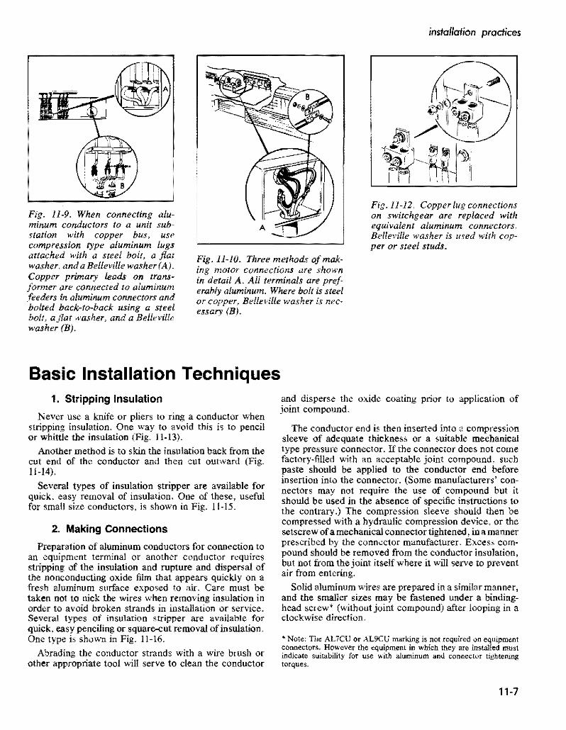
installation practices
Fig 11-9 When connecting alushyminum conductors to a unit subshystalion with copper bus use compression type aluminum lugs attached with a steel bolt a fiat washer and a Belleville washer (A) Copper primary leads on transshyformer are connected to aluminum feeders in aluminum connectors and bolted back-to-back using a steel bolt a fiat washer and a Belleville washer (B)
Basic Installation Techniques
Fig 11-10 Three methods of makshying motor connections are shown in detail A All terminals are prefshyerably aluminum Where bolt is steel or copper Belleville washer is necshyessary (B)
Fig 11-12 Copper lug connections on switchgear are repaced with equivalent aluminum connectors Belleville washer is used with copshyper or steel studs
1 Stripping Insulation
Never use a knife or pliers to ring a conductor when stripping insulation One way to avoid this is to pencil or whittle the insulation (Fig 11-13)
Another method is to skin the insulation back from the cut end of the conductor and then cut outward (Fig 11-14)
Several types of insulation stripper are available for quick easy removal of insulation One of these useful for small size conductors is shown in Fig 11-15
2 Making Connections
Preparation of aluminum conductors for connection to an equipment terminal or another conductor requires stripping of the insulation and rupture and dispersal of the nonconducting oxide film that appears quickly on a fresh aluminum surface exposed to air Care must be taken not to nick the wires when removing insulation in order to avoid broken strands in installation or service Seveltl types of insulation stripper are available for quick easy penciling or square-cut removal of insulation One type is shovn in Fig 11-16
Abrading the conductor strands with a wire brush or other appropriate tool will serve to clean the conductor
and disperse the oxide coating prior to application of joint compound
The conductor end is then inserted into a compression sleeve of adequate thickness or a suitable mechanical type pressure connector If the connector does not come factory-filled with an acceptable joint compound such paste should be applied to the conductor end before insertion into the connector (Some manufacturers conshynectors may not require the use of compound but it should be used in the absence of specific instructions to the contrary) The compression sleeve should then be compressed with a hydraulic compression device or the setscrew of a mechanical connector tightened in a manner prescribed by the connector manufacturer Excess comshypound should be removed from the conductor insulation but not from the joint itself where it will serve to prevent air from entering
Solid aluminum wires are prepared in a similar manner and the smaller sizes may be fastened under a bindingshyhead screw (without joint compound) after looping in a clockwise direction
Note The ALiCU or AL9CU marking is not required on equipment connectors However the equipment in which they are installed must indicate suitability for use with aluminum and connector tightening torques
11-7
covered and insulated aluminum wire and cable
Fig 11middot13 Never ring a cable-it may lead to a break Insulation should be removed as one would sharpen a pencil
Fig 11-14 Another safe way of removing insulation from conducshytor is to peel the insulation back and then cut outward
Fig 11-15 Use wire stripper for removing insulation from smaller wire sizes Match stripper notch to wire size
Fig 11-16 Penciling tool for removal of insulation in bevel configuration by rotation Several sizes are availshyable which by proper selection ofbushing are applicable to all usual sizes of cables This tool is particularly suitable for primary cables which have comparatively thick insulation
In making connections first strip the insulation as instructed heretofore Then apply joint compound if it is not already contained in the connector
If the connector is a mechanical screw type appJy the manufacturers recommended torque (Fig 11-17) In absence of specific torque recommendations use UL 468B torque values shown in Table II-I Ifacompression type crimp it as recommended by the manufacturer (Fig 11-18) Be sure to select the correct size die and close the tool completely for full compression Wipe off any excess compound Then tape the joint as instructed under Section BZ Or apply the inSUlating enclosure that comes with some types of connectors
3 Pulling Conductors in Conduit or Electrical Tubing
The following procedures are applicable to conduit of all types including aluminum
a Run a fish line through the conduit This may be done by attaching the line to a piston-type device which is propelled through the conduit by compressed air Another method is to push a round flexible speedometer type steel wire through the conduit Polyethylene fish tapes may be used for shorter runsshyup to about 100 feet
b Attach a clean-out brush to the fish line and behind it attach the pull line then pull both through the conduit by means of the fish line
c Attach the pull line to the conductor or conductors A basket grip over the insulation may be used for this purpose (Fig 11-19)
11-8
installation practices
Fig 11-18 Crimping tool must be fully closed Failure to close crimpshying 1001 will lead to an unsatisfacshytory and weak joint
Fig 11-17 Proper torque is imporshytant-over-tightening may sever the Fig 11-19 Basket grip wires Or break the filling undershytightening may lead to overheating and failure (See Table 11-2)
d Where conductors are pulled with a rope stagger j When conductor ends are prepared for pUlling be sUre the conductor ends and anchor in position with tape not to nick the stranded aluminum conductor during to provide maximum lIexibility around bends (Fig insulation removal Damaged strands can reduce the 11-20) pulling tension capabilities of the conductor To avoid
this pencil the insulation for removal as described above do not ring cut the insulation
k Follow all NEC requirements
Fora detailed description ofcalculating pulling tensions see the example given on page 11-11 on underground installations See Chapter 17 for a complete treatment of aluminum conductors in conduit
Fig 11-20 When a rope pull has to be used skin the cable ends and stagger them after locking with tape 4 Installation of Cables in Trays This will hold tie to a minimum Where aluminum cable is to be pulled in trays or cablecross section racks take the following precautions plus those applishy
cable to conduit e Try to feed conductors into conduit end closest to the a Where pulling attachments are used on the conductors
sharpest bend to reduce pulling tension cover them with rubber-like or plastic tapes to prevent pound Have pulling equipment with adequate power available scoring of the trays and installation sheaves during a
to make a steady pull on the cables without jerks conductor pull during the pulling operations b Use large-radius sheaves around bends and smaller
g Use pulling compound compatible with the conductor sheaves on the straight sections of cable support trays insulation as the conductors are fed into the conduit to facilitate cable installations to reduce the required to reduce coefficient of friction and required pulling pulling tensions and to prevent damage to stranded tension conductors or insulations
h For single conductors on a reel stagger reels one c Where cables are anchored on trays be sure straps behind the other while feeding in conduit to maintain or other cable anchoring devices do not cut into the equal pulling tensions and prevent conductors from insulation crossing over and jamming in the conduit d Cables installed in trays should follow the requireshy
I Wherever possible pull conductors in a downward ments of NEC Article 318 for the aUowable number direction to allow gravity to assist in pulling with of cables permitted in trays and their respective reduced tension ampacities
11middot9
covered and insulated aluminum wire and cable
e Straight cable tray runs may often be installed by simply laying thelightweight aluminum cables in place
f Be sure tray supports are capable of handling maxishymum weight of conductors and planned conductor additions in the future
5 Minimum Training Radii
Where permanent bends are made at terminations using aluminum building wire Table 11-5 indicates the minishymum bending radius as a multiple of the overall cable diameter Such bends should be made before the terminal is applied to minimize electrical contact distortion
6 Conductors in Vertical Raceways
The NEC under section 3()()19 stipulates that conducshytors in vertical raceways shall be supported As a general rule one cable support shall be provided at the top of the vertical raceway or as close to the top as is practical plus an additional support for each interval of spacing as shown in Table 11-6 An exception to this rule is that if the vertical riser is less than 25 of the spacing listed in the Table nO cable support shall be required
Installing Cable in Conduit or Duct
Theprocedures forinsertinga fish line or tape through a conduit or duct followed by a pull line andlor cable as required for the pull are well known and established as field practice and do not need extensive description here Aluminum conductors may be attached to pull line or cable by means of a factory-installed pulling eye by placing a basket grip around the conductors insulation (Fig 11-21) or by tying the line to a loop in the uninsulated part of the conductor (Fig 11-20) Steel pull cables used to pull conductors around bends in aluminum conduit runs may damage the conduit at the bend This is often avoided by using steel elbows with aluminum conduit or by use of a pull line that will not damage aluminum elbows
Pulls should be accomplished with steady tension and pulling speeds not exceeding 50 feet per minute Hard pulls can be eased if the reel if hand controlled and slack cable is guided into the conduit
Pulling tensions may be reduced by lubricating the cable surface However SOme lubricating materials have been found to adversely affect cable insulations or outer jackets In addition to cable pulling compounds this
TABLE 11-5 TRAINING RADII
For 600 V Cable Not in Conduit on Sheaves or While Under Tension
POWER CABLES WITHOUT METALLIC SHIELDING ON ARMOR The minimum recommended bending radii as muHiplies of 1I1e overall cable diameter given in the following tabulation are for both single and multi-conductor cable with or without lead sheath and without metallic shielding or armor
Minimum Training Radius Thickness of as multiple of cable diameter
Conductor Insulation Overall Diameter of CAble-Inches mils 1000 and Less 1001 to 2000 2001 and over
155 and less 4 5 6 170 to 310 5 6 7 325 and over 7 8 I
POWER CABLES WITH METALLIC SHIELDING OR ARMOR (a) Interlocked Armored Cables
The minimum recommended bending radius for all interlocked armored cables is in accordance with table above but not less than 7 times the overall diameter of the cable except as noted below (c) for tape shielded cable
(b) Flat Tape and Wire Armored Cables The minimum recommended bending radius for all flat tape armored and all wire armored cables is 12 times the overall diameter of cable
(c) Tape Chielded Cables For ali cables having metallic shielding tapes the minimum recommended bending radius is 12 times 1I1e overall diameter of the completed cable
(d) Wire Shielded Cables Wire Shielded Cables should have the same bending radius as power cables without metallic shielding tape Aepfilted loon ICEA 5-66-524 NpoundWA WC-7
11-10
instollation practices
TABLE 11-6
SUPPORTING CONDUCTORS IN VERTICAL RACEWAYS From 1987 NEe Table 300middot19 (a)
Conduelors
Aluminum Copper
No 18 to No B Not greater than 100 feet 100 feet
NO6 to No 0 Not greater than 200 feel 100 feel
No 00 to No 0000 Not greater than 180 feel 80 feet
2116 kernil to 350 kernil Not greater than 135 feet 60 feet
350 kernil to 500 kernil Not greater than 120 feet 50 feet
500 kernil to 750 kernil Not greater than 95 feet 40 feet
Above 750 kernil Not greater than 85 feet 35 feet
applies to potting and joint compounds adhesives tapes etc If in doubt compatibility of materials foreign to the insulation should be cleared through the cable manufacmiddot turer
A number of proprietary wire puUing lubricants and compounds are UL-listed and labeled to indicate the compounds compatibility with conductor coverings In all cases the manufacturers instructions should be obmiddot served
Allowable Pulling Tension
The following formulas can be used to calculate the maximum allowable tension that should be applied to the cables Note that these allowable tensions assume the pullshying eye is attached to the conductor Where the pulling line is attached to a basket grip that surrounds the insulation the pulling tension should not exceed 1000 100 It should be kept in mind that tension developed for straight runs per unit length is less than that for the portion of the cable in bends
L The maximum aJ~owable pulling tension if the pulling eye is aHached to the conductor
(Eq Hmiddotl)
where Pm Maximum allowable tension lb N Number of conductors being pulled simultaneously A Circular mil area of each conductor
(If conductors are of various sizes add the individshyual NA values)
K = Conductor stress factor
2 The maximum allowable pulling tension (Pm) cannot exceed 1000 Ib where cables are pulled with a basket grip however the tension per Eqs 11-1 or 1t-2 should nOL be exceeded
3 The matimum allowable pulling tension for cable in conduit
or duct bends (to prevent cable damage becallse of rubbing on sides of bend) must not exceed the following
Ib = 100 r (Eq Hmiddot2)
where Ptgt = Maximum allowable bend tension Ib r = Radius of curvature of the conduit or duct bend ft
Note The maximum aIIowable tension determined from Eqs 11-1 or 1l~2 should not be exceeded
4 For straight section of conduit or duct the pulling tension (lb) likely to be developed can be determined as follows
P=L w t (Eq Hmiddot3)
where p~ = Pulling tension in straight section Ib L Length of conduit or duct straight section ft 1 = Weight of cable (or cables) lb per ft t = Coefficient of friction
Note For a wen constructed conduit or duct with a lubricated cable f approximates 05 For less favorable conditions or with considerable curvature f may approximate 075
5 For curved sections of conduit or duct the pulling tension (lb) likely to be developed can be determined as follows
Ic =1 + 1 eta CEq 1l-4) where Pc = Total pulling tension Ib
Ps = Tension for straight section at pulling end Ib PI = Tension for straight section at feeding end Ib = Angle of bend in radians (I radian = 573 deg) e = Base of Naperian logarithms (2718) f = Coefficient of friction
Example Determine the maximum pulling tension required to install three single-conductor cables in a duct according to the arrangement in Fig 11-22 The cable specifications are
Three single conductor 40 AWG 600-volt aluminum cables with cross-linked PE insulation
Weight 3 290 IbM It = 087 Ib per ft Cable diameter each 0690 in
Coefficietlt of friction=O5 K valueQOOSshy
middotK 0008 for ~ hard aluminum conductors or 0004 for Y2 or J4II
hard aluminum
iIgtiFfR ~o 5 11-11
covered and insulated aluminum wire and cable
A Condttj~ or Doct Ckan)Ot Brush
B Kellems Grip
C Job Famianed Pulling BlUket
Fig 11middot21 Pulling cable in duct Pulling cable between junction boxes of conduit installations is similar
Using a single pulling eye attached to the three conductors and applyshying Eq 11~1 the maximum allowable pulling tension is
Pm=0008 X 3 X 211600=5078 Ib per Sq IImiddot I For the entire run from pull-box (I) to pull box (6) the tension
increments are as follows Sq
11middot3 At box (2) p == L X w X t == 100 X 087 X 05 == 435 Ib
f 0 05 X 1S71 11-4 At box (3) p == P X e = 435 X e
435 x 2194=954
11middot3 At box (4) P = 954 + (4 X w X tJ == 954 + (SO X 087 X 05) = )J72 Ib
0$ X 1571 114 At box (5) p == 1172 bull = 1172 X 2194 =
257llb
11middot3 At box (6) P 2571 + (4 X w X f) = 2571 + (15 X 087 X 05) = 2637 Ib
The total puning tension of 254 lb is far below the 5080 Ib limitation and the tension at each bend is far below the
11-12
recommendation per Eq 11-2 of 100 x 10 or 1000 lb Study of such examples shows that there is an advantage in puning cables from the pull box or manhole closest to the first bend This aids in reducing tension on the installed cable In this instance if the pull started at box (6) the final tension would be about half the above-found value
For a more complete treatment of cable puning in conshyduit the reader is referred to RC Rifenberg AlEE Tranmiddot sactions Dec 1953
Installing Directly Buried Power Cables
If cable placement can be started Defore sidewalks and other obstructions are installed the plowing-in method usually is the most economical method of burying power cable If soil conditions are unsuitable for plowing the
See also Aluminum Underground Distribution Reference Book
PULL BOX
50
PULL BOX
Fig 11-22 Diagram ocircuit layout to illustrate method of computing pulling tension
use of trenchers back hoes Or manual digging is custoshymary If the soil is rocky it should be screened to prevent cable damage Int is not sufficiently fine to closely cover the cable surface a four-inch thickness of sandy loam placed under and over the cable will improve the heat radiating quality of the soil
Duct Or conduit also should be used under streets or where access by digging to a buried cable is not practicable
Sufficient cable slack should be provided at risers and terminals to permit earth movement that may occur because of conductor thermal expansion frost and also as an allowance for future repair
Boards or slabs placed over the cable for mechanical protection should not be directly in contact with the cable but should be laid on an earth fill over the cable
Depth of burial ranges from about 30 to 48 inches for primary cable and from about 24 to 42 inches for secshyondary cable when buried separately On many systems both primary and secondary cables are buried in the same trench with no separation In many areas the trenches are shared jointly with other utilities notably communishycations-both telephone and television cables Joint use of trenches requires close collaboration on installation schedules but offers substantial economies to the sharing utilities
Initially a separation of one foot was required between primary power and communication cables and many comshypanies still require this separation An amendment to the NESC however permits random-lay (no deliberate separation) installation of communication and power cables in the same trenches with grounded wye power systems operating at voltages not in excess of 22 leV to
installation practices
ground ordelta systems operating at voltages not in excess of 53 kV phase to phase under certain conditions describshyed in NESC Section 35 Article 354 However joint use with very long single-phase primary circuits is not recomshymended because of the inductive pickUp of harmonics by the communication cables from the power cables
Care exercised in handling the cable during installation will help to avoid trouble later for damage sustained by the cable during installation has proved to be a major cause of subsequent cable failure
Many of these precautions have to do with making sure there is no insulation damage The cable is not susceptible to corrosion failure when insulation is unbroken even where moisture has gained entry into the conductor is some manner this fact has been determined in cable manufacshyturer laboratory tests and from research by utilities Migrashytion of moisture through damaged insulation in the presence of ac potential concentrates ions and promotes ac electrolysis
Cable transitions between overhead and underground usually employ the conventional factory-molded pothead of which special types are available for use in URD systems A termination is not reqnired however if the insulated aerial cable is also suitable for direct burial Such a cable can be carried directly down the pole Riser shields or conduit should be used to protect the cable on the riser pole to a point at least eight feet above ground level and should extend at least 12 inches below ground The riser shield must be solidly grounded to the system neutral and bonded to the lightning arrester to avoid transient potentials
Many other practices relating to buried cables and their connection to transformers to service entrances and tap connections in junction boxes and vaults are described in industry manuals Practice is gradually becoming standshyardized in the direction of increasing reliability and lowershying installation and maintenance costs in this most imshyportant segment of power distribution
The following suggestions will help to avoid failures from this cause they apply equally to cable and cable in pipe
1 Make sure that end seals are intact both while the cable is stored and installed to avoid entrance of water into the strands
2 If plowing is not used cables if at all possible should be payed out along the side of the trench from moving reels or carefully laid in the trench from stationary reels
3 The trench should not be dug before final grading is determined so cable will not be exposed or be too close to the surface
bull See also IEEE Conference Record 31C35 Special Technical Conference on Underground Distribution Sept 27~29 1966
11-13
covered and insulated aluminum wire and cable
TABLE 11middot7
I ICEA MINIMUM BENDING RADII FOR POWER CABLES
WlTHOtIT METAlliC SHIELDINGmiddot
I Minimum Bendine RHii as a Multiple of Cable Diameter
I cabl DO Inchbullbull
Tlllcimess of 1000 1001 2001 i
Insulation Inch I and less tD 2000 and OYer
0156 and Ie 4 5 6
I 0157 to 0312 5
i 6
7 0313 and over - 7 S
bull Only applicable for cable training bearing pressure limitation may require larger bending radii for cable tension
Data apply to single and multiple conductor cable also to wire-shielded cable Minimum bending radius for cables with metallic shielding tape is 12 Urnes the completed cable 00 The National Elecshytrical Code Section 300-34 requires 8 times fot non-Shielded and 12 times for shielded medium voltage cable bending radiI
4 In rocky soil areas use screened backfill Or sand to protect direct buried cable A 2-inch bedding is sufficient below but there should be a minimum cover of about 4 inches (The bedding and cover can be omitted when duct in conduit is used)
5 If boards concrete slabs etc are used above the cable for mechanical protection they should not be in direct contact to avoid shearing action when the soil settles Make sure boards are treated with preshyservatives that will not harm the cables insulation
6 Check the cable visually for damage before burial or installation in duct
7 When primaries are pulled into ducts or open trenches the use of a pulling grip over the cable is common rather than a pulling eye or other attachment conshynected directly to the conductor Duct should be carefully cleaned by pulling a plug through it to remove all burrs and obstructions To keep the cableshypulling tension within safe limits a lubricant approved for use with the specific insulation and insulation shield should be used
8 When doing permanent training make sure that the minimum bending radii are observed (see Table 11-7) Make every effort to provide more radius than these values at reel payout risers plow guides duct bend etc
9 Make sure splices and other connections are made in accordance with manufacturers recommendashytions
10 Double check to make sure proper backfilling is done Rock fill should be kept away from the cables to
prevent damage Compacting should be carefully done and air spaces minimized
11 Proof test the cable after installation to insure integshyrity of insulation and splices (See Table 11-8)
12 Dont overfuse the cable Because of the paucity of failures many utilities prefer to use one-shot fuses as an added protective measure for the cable
Many of these precautions have to do with making sure there is nO insulation damage The conductor in 600 volt cables is not susceptible to corrosion failure when insulation is unbroken and moisture has not gained entry into the conductor When moisture enters a break in insulation however ac electrolysis begins
Splicing and Terminating in Underground Systems
The revolution in underground distribution system design has included the devices and methods used for making splices connections and terminations The obshyjective here has been to reduce the amount of skill and time required in the field so as to reduce the installation costs More prefabrication is being done under factoryshycontrolled conditions and the need for heating and pouring of insulating compounds or extensive taping in the field has been greatly reduced
Aluminum connectors and terminating devices should be used with aluminum conductors so as to avoid differshyential thermal expansion and contraction upon heating and cooling that could result from the use of connectors of dissimilar metals Compression type connectors and lugs applied with a tool and die are widely used It is
11-14
instolation practices
TABLE 11middot8
ICEA RECOMMENDED de PRooFmiddotTEST VOLTAGES (15 Minute Test)
Polyethylene or CrossmiddotLinked Polyethylene Insulatd cables
ProofmiddotTestRated Insulation Voltage 1mCircuit Thicllnm (Mils)Voltage Installation
i
25 5001middot 8000 115 2001middot 5000 90
35 8001middot15000 175 55
15001 middot25000 80 25001 middot28000
260 85280
28001middot 35000 345 100
important in installing these devices that a die of the correct size be used and full pressure be applied in order to obtain permanently sound connections
600 Voll Secondary Clrcuils
In this regard connector manufacturers have made important advances in the design of connection devices for secondary circuits There are far too many types to describe them all in this handbook However a couple of examples are given below to indicate the types of premiddot molded splices and terminations that are currently availmiddot able for this type of service
(a) Underground Direct Burial Splice 600 volt insulated cable splices are available for conductor sizes 6 AWG stranded through 1000 kcmil and can be completely installed and sealed without taping or compound filling Typical installation procedure is (Fig 11middot23) as follows
Step A
Lubricate both insulating splice caps by applying a small amount of the supplied lubricant to the inside diameter of the cap at both the housing end and also to the inside diameter at the conductor hole end For easier assembly of the insulating caps to the conshyductor jt is recommended that the insulation at the end of the conductor be penciled before stripping Then place the proper caps over each conductor end
Step B
Strip correct length of conductor insulation for the splice connector being used Place splice housing over end of conductor and assemble one cap to housing Large end of cap should cover the knurled line of the housing body
Step C
Wire brush exposed cable ends and then immediately
insert cables into connector Start crimping splice onto conductor as per manufacturers instructions Continue crimping to ends of splice overlapping crimps 118 inch minimum Wipe away all excess oxide inhibitor
Step D Place housing with the assembled cap over splice connection and snap remaining cap in place on housing to complete the sealed splice When caps are correctly installed the large ends should cover the knurled lines on both ends of the housing body
(b) Secondary 600 V Underground Terminations There are several different designs of connector products which are approved for use in underground 600 V electric power systems They supply the needs of connectors required for residential or commercial use direct burial below grade vaults pedestal or pad mounted equipment bolted or compression fittings and in any combination
Fig 11-24 shows a representative group of these fittings which are designed to accommodate a wide range of conductors Their installation is straightforward and reshyquires no field cutting or hand taping for insulation or environmental sealing The threaded stud connector for transformers is such that the connector can be detached from the transformer without disconnecting the conducmiddot tors
Primary Circuits
Termination of primary underground cables requires some type of stress relief Initially these were made up by taping a stress cone which proved to be one of the most tedious and time-consuming jobs for the field man Today most utilities use some form of preshaped Or prefabricated stress cone which can be installed in a fraction of the time
11-15
-----------
covered and insulated aluminum wire and coble
B IN4fyenSUIATlNGCAP rNO PENCILING
__ bull ( REQUIRED
- -f -- -~I L
c - ~ _shy
D
STRIP os lENGTH
INSUATINi CAP KNURLED LINES
- - - - -HHH+shy~ SPUCE HOUSING
~~~-~~~-$PUCE CONNECTOR INSULATING CAP bull----- E--- KNURLEO
LINES
l__________________________________________________________~c~ou_n_e~~8~la~Ok~b_ria~n~C~O~_J Fig 11middot23 Secondary 600 V Underground Splice Kit showing sequence of assembly steps
Typical terminations for primary cables indicate that molded precut tape and porcelain types are used indoors while porcelain units are most often used outdoors One of the most significant developments in primary cable terminations has been the introduction of plugmiddotin conmiddot nectors for joining the cables to equipment or other cables With these devices it is almost as easy to conncct a primary cable as to plug in or remove an appliance cord from a convenience outlet
11middot16
The concept of premolded stress relief takes the fabshyrication of a stress relief COre away from the field and into the factory with its controlled environment leaving just the assembly to the field installer Elastomeric conshynections form a very convenient inexpensive and reliable method of connecting or terminating high voltage cables Power cable loadbreak elbows in the 35 kV class were introduced to the industry in 1983 with designs for 15 kV and 25 kV following in 1985
installation practices
CAP for porcelain bushings
Set screw s In seu connector are light shyened dow n on flat side 01 Adapter pressure deforms Adapter to lock Ad~pter and seu conneCtor to threaded stud un screws can be b8 C k~d -ofl Adapter and seu conn eCt or removed from transformer without remo ving conductor from connector
Thr eaded Stud Secondary Bush ing
l Adapter Scr6W5 on threaded tud of bllshing Iat side 01 Adapter mUSt be oriented to receive sel Ic rews
seu connector slips o ver Ad apUlr All Adapters have ~
0-ring5 In Sealing Cep same 0 0 all seu con shyseal arond Bushing neclors ho ve seme Adepter Neck and seu connector cavit y 10
Fig -24 Some typical 600 V underground termination fillings
Through the combined efforts of the connector and Some typical applications of premolded products are apparatus manufacturers and the utilities there is availshy at pulling or junction boxes cable to equipment connecshyabte today an array of premolded products that exhibit a tons and cable to cable connections All of these comshyhigh degree of safety reliability and flexibility ponents are designed and tested to be in compliance with
ANSUIEEE Standard 386-1985 Separable Insulated middotSee James W Fitzhughs paper Exploring the Application of Connectors for Power Distribution Systems above 600 Premolded Products for High Voltage Power Systems Volts
11-17
covered and insulated aluminum WIre and cable
Prlo(o counesy 01 ELASTIMQLO
Fig -25 Power cable joint for use af 15 k V or 25 kV
Primal( Voltage Circuits
A cutaway view of an up-to-date power cable j0i nt is shown in Fig 11-25 The cloverleaf design allows the joint to operate at lower temperatures
While installation of premolded devices are si milar conditions may vary depending on the device the cable and the manufacturer of the splice or termination In all cases full instructions will be provided and should be followed Additional typical designs are shown in Fig 11-26
Development work in splicing connecting and tershymina ting devices is still proceeding Users thus are ad vised to keep posted on the latest designs being offered by the connector manufacturers in order to achieve greatest economies in making cable splices connections a nd terminations
Though recent trends have been toward the use of premolded splicing and terminating devices it is still necessary or desirable in some circumstances to make hand-taped joints by traditional methods Because of this the details of making a hand-taped concentric neutral st raight splice are given below Details of the joint are shown in Fig 11 -27
The following are the in struction s to be generally based in making the joint illustrated in Fig 11-27 They are for a typical hand-taped primary cable splice All splices and terminations should be made by a qualified cable splicer in accordance with the manufacturers instructions and recommendations
I Study splice drawing and instructions
2 Train cables into final position and overlap for 18 inches to afford enough excess concentric wire for final jointing
11-18
3 Tem porarily wrap a number of turn s of tape over the outer concentric wires at least 18 inches from the centerline of the splice
4 Carefully unwrap outer concent ric wires and temshyporarily remove them out of the splice area being sure not to damage or kink them
TABLE -9 Recommending Taping Dimensions
Inlull-Ok A B C 0 K
Thkkmiddot u
15KV
175P One- Iall
Connector Zmiddot 4 2A oj- 14~ 38 220 lenglh
25KV
One-tlall 2so Connecl0r 2W 514 2A + 1112 716
length
35KV
One-hall 916~345 7Connector 2A + 22
length 5 Cut off excess cable at splice centerine
6 Remove outer semiconducting jacket for a di stance of (A + I + B + C) inches from each cable making sure th~t the insulation is not damaged during the removal operation All traces of the semiconducting jacket must be removed by a nonconductive abrasive or rasp
7 Remove the insulation from each conductor for a distance of (A + I) inches making sure that the conductor is not nicked during the removal operation
installation practices
Assembly of Tee Splice and Tap Devices
bull Straight Line Splice
Disconnectible Straight Line Splice
Loadbreak Elbow
Connectors
Modular Cable Terminator
Fig 11-26 Some typical primary voltage premolded splicing and terminating devices
11-19
covered and insulated aluminum wire and cable
Splicing-15kV-25kV-35kV Primary Cables-Hand Taped Splice Single conductor with concentriC neutral straight splice (conventional or crossmiddotlinked polyethylene insulated solid or stranded) for grounded neutral service
Concentric Wires TwiSled amp Spliced in Connector
One Hlfmiddotlapped Laye Friction Tape Halfmiddotlapped layer SemlmiddotConducting SelfmiddotFusing Tape
Self-Vulcanizing Tape One Halfmiddotlapped layer 10 K Thickn Tinned Copper Mesh Braid
Two Half-Lapped layers Self-Fusing middotA = OnemiddotHalf Connector lengthRubber-Like Tape
Fig 11middot27 Details ofa taped primary cable joint
Penciling tools will remove the insulation as well as provide smooth penciled surface
8 Apply the required compression connector on each cable following the connector manufacturers recmiddot ommended procedure Note It is recommended that a smooth surface type connector be used--not an indented type If an indented type is used fill the indents with a pliable insulation putty
9 Remove all sharp edges from compressed connector using a file Or heavy abrasive cloth
10 Pencil the ends of the polyethylene insulation for a distance of (B) inches Be sure not to cut into the insulation or damage the conductor during the penshyciling procedure Buff the insulation pencils if they are not smooth with a nonconductive abrasive or rasp This step would be completed with a penciling tool (See Step 7 above)
II Clean all exposed surfaces with a nontoxic and nonflammable solvent and allow to dry Care must be taken in wiping the black conductingjackets since this may smear over the insulation surface
12 Apply one half-lapped layer of semiconducting tape (Bishop Tape No 17 or equivalent) over the exposed conductor and connector Tape should just contact the edge of the cable insulation and be applied with enough tension to conform to the connector
13 Apply halflapped layer of high voltage selfmiddotfusing tape with manufacturers recommended tension starting at connector centerline and building up to the level of be connector in areas between insulation pencil and connector by evenly wrapping tape back and forth across the connector Apply splice tape buildup to a thickness of K inches over the connector and for a longitudinal distance of D inches tapering at the ends
14 Apply one hulf-Iapped layer of selfmiddotfusing semiconshyducting tape over insulating tape buildup extending I inch beyond insulating tape onto be semiconducting jacket on each side of splice The semiconducting tape should be applied with adequate tension
15 Apply one half-lapped layer of tinned copper mesh braid over the semiconducting tape and extend I inch at each end of splice The tinned copper mesh braid
11-20
Insulating Tope
Fflction Tape
Rain Shield
r-h~bj--Insulaling Tope
Melol Grounding Strap
installation practices
should be wrapped as tight as possible and taping should be started at the centerline of tbe splice using two portions of tinned copper mesh braid
16 Apply two solder lines 180 degrees apart for the full length of the mesh braid making sure that the heat does not remian in one spot too long to damage the cable insulation or tapes
17 Tie the concentric outer wires in place using wraps of No 14 AWG tinned or bare copper wire and tack solder in place
18 Apply two half-lapped layers of a self-fusing high voltage tape OVer the outer braid with minimum tension
19 Apply one half-lapped layer of jacket tape over tbe mesb braid to the edge of the concentric wires at each end of the splice
20 Twist the concentric wires together and cut off excess length Place the formed wires into the proper sized mechanical (or compression) connector and splice in place to form low resistance joint following the connector manufacturers recommended procedure
o Insuloling Tope --IO~
Conduclor --+0
Coble Insulolion --1~
Insuloling Tope
Friclion Tope
Rain S~ield
Bios-Cui I nsuloting Tope
Mesh Shielding Braid
Friction Tope
1t1--Stress-Re lie Cone
Coble Shielding Tope --Hic1--J
Jacket
A Single conductor outdoor termination
Terminal Lug
Mesh Shielding Braid
+----Jackel
B 3-Conductor outdoor termination
Terminating Detail
The construction details of secondary or primary cable terminations depend on whether the termination is outshydoor indoor or from underground and wbether it is horizontal for connection to an equipment terminal or vershytical for connection to another conductor Trifurcating assemblies are also used for terminating a three-conductor cable so the urunsulated terminals are well separated (Fig 11-28)
Terminations usually are either of the pothead type or the built-up stress-relief type Both types provide extra insulation close to the actual termination ofthe conductor to provide protection against the extra voltage at these locations
Primarily potheads of plastic insulating materials are used with primary and secondary URD systems altbough porcelain potheads and semi-assembled built-ut sess relief cones (or kits that facilitate tbeir qllick assemt) _e still used for this application (Fig ll-16)
Stress-relief cones are also required in cable splices
Terminal Lug o o
Ilir--Conductor It-lt-Insulang Tope
Fig 11-28 Typical terminations S-lSkV
11-21
covered and insulated aluminum WIre and cable
where there is a change of conductor size the variation of current density in the adjacent conductors creates dielectric stress variations that occur when a cable is terminated
The detailed methods of terminating shielded and nonshyshielded cables closely resemble those used for splicing except that the termination process requires the inclusion of a stress-relief cone or a pothead and if the installation is outdoor and vertical the addition of a rain shield to shed water from the cable insulation is customary Descriptive details are supplied by cable and accessory manufacturers with dimensions for various sizes and voltages The accomshypanying illustrations list the successive operations The precautionary recommendations mentioned in relation to cable splicing also apply to terminating procedure subject
1 TERMINAL CONNECTOR The universal rod connector attaches to the power source
2 MOLDED RUBBER CAP Presses over top of tenninator with an intershyference fit to provide complete wsterseal in~ tegrity
3 RETAINING WASHER Mechanically prevents any cable slippage within terminator
4 TERMINATOR HOUSING Molded of special EPDM compounds lor funcshytional reliability and long life Actual creep distance is 18 (457 em)
5 CABLE INSULATION Primary insulation is provided since cable insulation carries through the terminator
6 INTERFERENCE FIT Molded insulating EPDM exerts unffonn conshycentric pressure on insulation of cable to provide required creepmiddotpatl1 length and washyterseat
7 MOLDED STRESS RELIEF Factory-tested molded stress relief assures proper stress relief for terminating cable A patented Elastimold feature
8 GROUND STRAP Provides a convenient point to connet a ground wire to the molded conductive shield and places the molded shield at ground potential
Courtesy Amerace Corp Elastimold Div
to such changes as appear in manufacturers instructional manuals
The cross-section of a molded terminal connector is shown in Fig 11-29 illustrating the component part ofa connector designed for conductors up to 25 kV It is suitable for uSe on solid dielectric cables and can be applied directly on cables with extruded semi-conductive shields including full neutral concentric It will accomshymodate aluminum conductors in the range of No 6 to 410 AWG with an insulation thickness of 0495 to 1115 Mter proper cable preparation the terminal connector is slid down over the bared cable insulation until it bottoms On the cable shield No special tools or potting compounds are required for the assembly of this type of fitting
Fig 11-29 Typical single conductor molded pothead for cable termination
11-22
Installing Aerial Insulated Cables
Single insulated or covered overhead primary aluminum conductors suspended from insulators sometimes are used in tree areas or similar locations Their installation is simishylar to that of bare conductors as described in Chapter 5 The span lengths usually are moderate so that sag and tension values generally are obtained from tables Howshyever for unusual spans sag-tension charts can be comshyputed or are available from conductor suppliers For aluminum 1350 conductors or less than hard tempers adjustment must be made for reduction of strength
For economic reasons however most overhead spans of insulated power conductors are in the form of preasshysembled or field-assembled multi-conductor cables susshypended from a bare messenger Insulator support is not required and space is saved by using a single-multi-conshyductor cable The conductors may be spiraled around the messenger or arranged paraliel to it as described 10
Chapter 7 Messenger supported cables are in two groups
Preassembled aerial cables (to 35 kV) Aerial cable assemblies (0 to 600 volts)
Primary Aerial Cables
The messenger size for primary cables is determined by the required strength except that for single-phase prishymary circuits (No 2 A WG or smaller) where the messhysenger also serves as a neutral conductor the conductance of the messenger must equal that of the insulated conshyductor Bare messengers not used as neutral conductors are often used also as a part of relaying circuits as a part of the grounding circuit for the insulation shielding and as an auxiliary to a common-neutral For these reasons specifications for multi-conductor primary cables with bare messengers usually specify the ohmic resistance of the messenger The combination of strength and moderate electrical resistance requirements of such non-neutral messhysengers has led to wide acceptance of composites of aluminum and of steel (Alumoweld) for the make-up of the messenger
Messenger sizes are such that the normal initial sagging tension at 60F will not exceed 30 of its rated strength and its maximum tension will not exceed 50 of its rated strength at the fully loaded condition Physical details of the cables used for the messengers listed in Tables 11-10 and II-II can be found in Tables 4-5 (1350-Hl9) 4-12 (6201-T81) and 4-14 (ACSR) These messenger sizes conform to the ICBA recommendation that the initial sag be such that the final sag be not less than 1667 of the span length
Stringing sag and tension charts are supplied by cable manufacturers as an aid to circuit design for light medium or heavy loading conditions (NESC see Table 5-1) for use as described in Chapter 5 However in most instances the spans are of moderate length so suitable sag-tension values may be obtained directly or interpolated from manushy
installation practices
faeturer-supplied tables that Jist initial and final values for 100 125 and 150 ft spans
For the installer of the cable the most useful tabular values are those for initial sag and tension usually for 60degF but a correction factor is applied if the installation temperature differs from 60F The final sag and tension values for the various NESC loading districts then will meet requirements as to the percent that messenger tension bears to its ultimate breaking strength and the manufacshyturers table will confirm this if required The messengers for preassembled primary cables are not neutral conducshytors but high conductance is useful for grounding or signal purposes hence the equivalent conductor rating is usually listed for the messenger For this reason various combinashytions of steel 1350 aluminum and high-strength alloy aluminum are often used for primary aerial messengers
Table 11-10 is extracted from more complete tables in order to show the form in which such tables are supplied Although this table shows use of a combination messenger made of 1350 aluminum strands assembled with strands of aluminum-clad steel other messengers are similarly used of high strength ACSR as well as combinations of 6201 aluminum with steel reinforcement (AACSR)
Fig 11-30 depicts several kinds of fittings and accesshysories used when installing messengers and preassembled aerial cables some of which also apply to preassembled secondary and service-drop cables
Neutral-Supported Secondary and Service-Drop Cables
Preassembled aluminum insulated multi-conductor cables supported by bare neutral messenger conductors have practically become standard for secondary aerial cirshycuits and service drops Subject to the NEC limitation of 300 volts to ground for bare neutrals the triplex form (two insulated conductors preassembled with a bare neushytral) supplies the usual single-phase three-wire circuits Similar quadruplex cables (three insulated conductors) if conneeted to a three-phase Y source supplies low-voltage three-phase loads
The neutral messengers of such cables are selected on basis of strength and conductivity either with conducshytivity equal to that ofa phase conductor or as a reduced neutral having conductivity not less than one-half that of a phase conductor depending on service requirements Tables in Chapter 4 show as mentioned above data regarding bare neutral messengers for such cables Chapshyter 10 describes various types ofcables Fig 11-31 depicts installation details for usual conditions of installation of the secondary cable and the service-drop taps extending from it Initial sag-and-tension data for preassembled triplex aluminum cables with full- and reduced-size neushytrals are in Table 11-11 for the various NESC loadings for 125 ft spans
11-23
3 Bolt Guy Clamp
2 Bott Unieurorsal GUY CHp
Split Bolt Connector
covered and insulated aluminum wire and cable
3 Bolt GUY Clamp
Oval Eye Bolt
Vise Type Connectors
The notation on Table 1I-1I with regard to initial sag values for other spans than 125 ft is based on Eq 5-2 but it is only approximate hence it is available to obtain correct values from the cable manufacturer
The sag-tension values of Table 11-11 are for initial unshyloaded conditions at 60F The sag eventually will inshycrease to the final value and the tension correspondingly will decrease as a result of long-time creep When fully loaded according to NESC values the sag and tension both will increase and as temperature drops to OCF under Heavy-Loading conditions the sag decreases and tension
F
2 Bolt Universal GUY Clip
B
E
Strand Connector
increase~ Thus for 20-20 cable with aluminum-alloy 6201 me nger the initial stringing sag-tension of 13 inshy865 Ib becomes 24 in-1955 Ib (see Chapter 5)
The sag-tension values under conditions of maximum NESC loading are useful for circuit design because they indicate minimum clearances under the cable and also verify that there is the specified margin between actual tension and the rated breaking strength of the messenger However tables imilar to Table H-ll for initial stringing conditions are us~d as a basis for installation which is the subject considered in this chapter
o
c
Fig 11-30 Typical details for supporting and dead-ending cables messengers and guy wires on poles
11-24
installation praclices
A
Prelcftllel
~ A V vv
Insulated Clevs
ToPIt
o
DeltldEno tor EQuol)
1 I
B
I Messger Suspesion CImp
Connector (Before Tpig)
c
Plastic Guard Plastic Guard
Messenger Suspension
Clomp
Fig 11-31 Typical installation details for secondary triplex cables neutral-messenger-supported showing service-drop taps and other details
A-Dead-end at pole shuwing also application of serviceshydrop span clamp
B-Double service-drop taps at service-drop span clamp and messenger suspension clamp at pole
C--Service-drop T tap near pole
Tope or Clip
C(lmp(e$$iO_~h~~Connettor_
I I I Prefarmed Oeoo~End (or EquOI )
D-Clevis support at pole for directional change of less than 45deg
E-Dead-end support at pole for directional change of mOre than 45deg
Notes Compression connections are to be taped even though not so shuwn Poles are to be suitably guyed to resist unbalanced forces Armor rods are used where abraSion is likely See Chapter 5 for additional details of armor rods and the like
11-25
covered and insulated aluminum wire and cable
TABLE 11-10
Representative Values extracted from Tables Supplied by
Cable Manufacturer for Initial Sag-and-Tension Values at
60F suitable for Light or Heavy NESC Districtgt
For Preassembled Primary AerialSmiddotIC Cables with AWAC Messenger
Conductor I Calgtl Span Length in FeetI ISize AWG or Kcmi
I
Messe
ISize
nger
Rated Strength
Assembly (2) Diam
in Weight 100 125 150 Ibltt Satinches (3)
100 i 125 I 150 Tensionmiddotlb (11
5000 Volt Unshielded (Class B concentric stranded aluminum cross-linked polyethylene insulation)
6 3-34 1
20 40 350 500 3middot25 750 2middot215
1000 10-25
UbI 7700
11300 13500 19500
1251 0421 19
1575 1770 2007 2374 2693 3215 3695
0645 I 0827 1100 19 1600 2158 3076 4053
23
23
28 337 428 509 516 780655
662 840 1000 27 1118 1364880
1280 1626 1983 21931726 2675
2461 i 3126 3813 3242 I 4119 5024
15()(J( Volt Shielded Grounded Neutral (Class B concentric stranded aluminum semi-con tape strand shield 0175 in XLPE insulation extruded semimiddotcon PE No 22 AWG copper concentric Mylar tape PVC jacket)
2 3-34 110 40 3middot25 350 10-215 500 750 55650()j307)
1000
7700
11300 19500
26900
2459 1379 19 2618 1606 3006 2215 3504 3075
3789 3696
4575 5039 5_079 6390
23 27
28
27
28
31
1122 11418 1739 1306 1645 2024
1801 2269 2679
2500 3151 3720 3005 3787 4659
4032 5040 6048
5031 J64()()~ 1 Initial tension lS such that the final temiion will not exceed 25 percent of rated strength at 60degF I for
light or Heavy NESC loading districts 2 Includes weight of messenger and binder tape
3 Initial sag is such that final sag approximately conforms to ICEA recommendation of 1667 percent of span length
11-26
instollation practices
TABLE 11-11
Typical Initial Stringing Sag and Tension Values for
Three-Conductor Sell-Supported Polyethylene Service-Drop and
Secondary Cable (Triplexl lor 125 ft span at 60degF
lor Various NESC Loading Districts (see Table 5-1
Note For roughly approximate value for spans of 100 ft and 150 ft multiply the initial sag values for 125 ft span by 064 for l00ft
span and by 145 for 150-ft span retaining the initial tension values for 125 ft span These approximations are less accurate for
the Heavy Loading District More accu rate values for spans other than for 125 ft are obtainable from cable manufacturer
I Neutral
Messenger I NESC Light-Loading
NiSC Medium-Loading
NESC
Heavy-loading Con- I Oistrict District District
ductor Size Rated Size AWG Initial Inital Initial Initial Initial InitialStrellgth r
AWG (or EquivJ Ib Sag Tension Sag Tension Sag Tension
ALUMINUM ALLOY 6201 NEUTRAL MESSENGER
4
2 10
20
4 2
IO 20
1760 2800 4460 5390
8 8 8 8
467 750
1195 1415
10 10 8
10
410 680
1060 1255
16 12 1 I
13
250 553 875 865
ACSR NEUTRAL MESSENGER
6 1190 10 2906 10 305 4 18604 10 445 8 415 2 2 11 5752850 10 660
4380IO10 10 1005 12 865 20 531020 10 1255 12 1070
REDUCED ACSR NEUTRAL MESSENGER
12 350 2 4 6 1190 12 295
4 13 445 13 435 110 2
1860 2850 13 670 14 600
20 3550 13 835 16 730I I ALUMINUM NEUTRAL MESSENGER (Aluminum 1350)
54 44
19 195 19 295 23 410
6 6 560 4 4 881 2 2 1350
10 110 1990
26 91 19 195 17 385 19 485
29 98 11 375 1 I 600 12 840 13 975
34 17 13 14
104 72 49 40
105 330 655 755
23 53
115 230
These jnitial sag-tension values are based on NESC loading limits for REA systems that is loaded tension is not to exceed 5000 of messenger rated strength final stringing tension is not to exceed 251 Of rated strength and initial stringing tension is not to exceed 33~13 Of rated strength
11-27
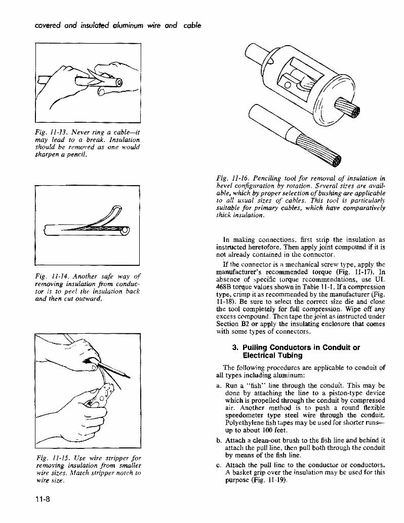
covered and insulated aluminum wire and cable
Fig 11middot13 Never ring a cable-it may lead to a break Insulation should be removed as one would sharpen a pencil
Fig 11-14 Another safe way of removing insulation from conducshytor is to peel the insulation back and then cut outward
Fig 11-15 Use wire stripper for removing insulation from smaller wire sizes Match stripper notch to wire size
Fig 11-16 Penciling tool for removal of insulation in bevel configuration by rotation Several sizes are availshyable which by proper selection ofbushing are applicable to all usual sizes of cables This tool is particularly suitable for primary cables which have comparatively thick insulation
In making connections first strip the insulation as instructed heretofore Then apply joint compound if it is not already contained in the connector
If the connector is a mechanical screw type appJy the manufacturers recommended torque (Fig 11-17) In absence of specific torque recommendations use UL 468B torque values shown in Table II-I Ifacompression type crimp it as recommended by the manufacturer (Fig 11-18) Be sure to select the correct size die and close the tool completely for full compression Wipe off any excess compound Then tape the joint as instructed under Section BZ Or apply the inSUlating enclosure that comes with some types of connectors
3 Pulling Conductors in Conduit or Electrical Tubing
The following procedures are applicable to conduit of all types including aluminum
a Run a fish line through the conduit This may be done by attaching the line to a piston-type device which is propelled through the conduit by compressed air Another method is to push a round flexible speedometer type steel wire through the conduit Polyethylene fish tapes may be used for shorter runsshyup to about 100 feet
b Attach a clean-out brush to the fish line and behind it attach the pull line then pull both through the conduit by means of the fish line
c Attach the pull line to the conductor or conductors A basket grip over the insulation may be used for this purpose (Fig 11-19)
11-8
installation practices
Fig 11-18 Crimping tool must be fully closed Failure to close crimpshying 1001 will lead to an unsatisfacshytory and weak joint
Fig 11-17 Proper torque is imporshytant-over-tightening may sever the Fig 11-19 Basket grip wires Or break the filling undershytightening may lead to overheating and failure (See Table 11-2)
d Where conductors are pulled with a rope stagger j When conductor ends are prepared for pUlling be sUre the conductor ends and anchor in position with tape not to nick the stranded aluminum conductor during to provide maximum lIexibility around bends (Fig insulation removal Damaged strands can reduce the 11-20) pulling tension capabilities of the conductor To avoid
this pencil the insulation for removal as described above do not ring cut the insulation
k Follow all NEC requirements
Fora detailed description ofcalculating pulling tensions see the example given on page 11-11 on underground installations See Chapter 17 for a complete treatment of aluminum conductors in conduit
Fig 11-20 When a rope pull has to be used skin the cable ends and stagger them after locking with tape 4 Installation of Cables in Trays This will hold tie to a minimum Where aluminum cable is to be pulled in trays or cablecross section racks take the following precautions plus those applishy
cable to conduit e Try to feed conductors into conduit end closest to the a Where pulling attachments are used on the conductors
sharpest bend to reduce pulling tension cover them with rubber-like or plastic tapes to prevent pound Have pulling equipment with adequate power available scoring of the trays and installation sheaves during a
to make a steady pull on the cables without jerks conductor pull during the pulling operations b Use large-radius sheaves around bends and smaller
g Use pulling compound compatible with the conductor sheaves on the straight sections of cable support trays insulation as the conductors are fed into the conduit to facilitate cable installations to reduce the required to reduce coefficient of friction and required pulling pulling tensions and to prevent damage to stranded tension conductors or insulations
h For single conductors on a reel stagger reels one c Where cables are anchored on trays be sure straps behind the other while feeding in conduit to maintain or other cable anchoring devices do not cut into the equal pulling tensions and prevent conductors from insulation crossing over and jamming in the conduit d Cables installed in trays should follow the requireshy
I Wherever possible pull conductors in a downward ments of NEC Article 318 for the aUowable number direction to allow gravity to assist in pulling with of cables permitted in trays and their respective reduced tension ampacities
11middot9
covered and insulated aluminum wire and cable
e Straight cable tray runs may often be installed by simply laying thelightweight aluminum cables in place
f Be sure tray supports are capable of handling maxishymum weight of conductors and planned conductor additions in the future
5 Minimum Training Radii
Where permanent bends are made at terminations using aluminum building wire Table 11-5 indicates the minishymum bending radius as a multiple of the overall cable diameter Such bends should be made before the terminal is applied to minimize electrical contact distortion
6 Conductors in Vertical Raceways
The NEC under section 3()()19 stipulates that conducshytors in vertical raceways shall be supported As a general rule one cable support shall be provided at the top of the vertical raceway or as close to the top as is practical plus an additional support for each interval of spacing as shown in Table 11-6 An exception to this rule is that if the vertical riser is less than 25 of the spacing listed in the Table nO cable support shall be required
Installing Cable in Conduit or Duct
Theprocedures forinsertinga fish line or tape through a conduit or duct followed by a pull line andlor cable as required for the pull are well known and established as field practice and do not need extensive description here Aluminum conductors may be attached to pull line or cable by means of a factory-installed pulling eye by placing a basket grip around the conductors insulation (Fig 11-21) or by tying the line to a loop in the uninsulated part of the conductor (Fig 11-20) Steel pull cables used to pull conductors around bends in aluminum conduit runs may damage the conduit at the bend This is often avoided by using steel elbows with aluminum conduit or by use of a pull line that will not damage aluminum elbows
Pulls should be accomplished with steady tension and pulling speeds not exceeding 50 feet per minute Hard pulls can be eased if the reel if hand controlled and slack cable is guided into the conduit
Pulling tensions may be reduced by lubricating the cable surface However SOme lubricating materials have been found to adversely affect cable insulations or outer jackets In addition to cable pulling compounds this
TABLE 11-5 TRAINING RADII
For 600 V Cable Not in Conduit on Sheaves or While Under Tension
POWER CABLES WITHOUT METALLIC SHIELDING ON ARMOR The minimum recommended bending radii as muHiplies of 1I1e overall cable diameter given in the following tabulation are for both single and multi-conductor cable with or without lead sheath and without metallic shielding or armor
Minimum Training Radius Thickness of as multiple of cable diameter
Conductor Insulation Overall Diameter of CAble-Inches mils 1000 and Less 1001 to 2000 2001 and over
155 and less 4 5 6 170 to 310 5 6 7 325 and over 7 8 I
POWER CABLES WITH METALLIC SHIELDING OR ARMOR (a) Interlocked Armored Cables
The minimum recommended bending radius for all interlocked armored cables is in accordance with table above but not less than 7 times the overall diameter of the cable except as noted below (c) for tape shielded cable
(b) Flat Tape and Wire Armored Cables The minimum recommended bending radius for all flat tape armored and all wire armored cables is 12 times the overall diameter of cable
(c) Tape Chielded Cables For ali cables having metallic shielding tapes the minimum recommended bending radius is 12 times 1I1e overall diameter of the completed cable
(d) Wire Shielded Cables Wire Shielded Cables should have the same bending radius as power cables without metallic shielding tape Aepfilted loon ICEA 5-66-524 NpoundWA WC-7
11-10
instollation practices
TABLE 11-6
SUPPORTING CONDUCTORS IN VERTICAL RACEWAYS From 1987 NEe Table 300middot19 (a)
Conduelors
Aluminum Copper
No 18 to No B Not greater than 100 feet 100 feet
NO6 to No 0 Not greater than 200 feel 100 feel
No 00 to No 0000 Not greater than 180 feel 80 feet
2116 kernil to 350 kernil Not greater than 135 feet 60 feet
350 kernil to 500 kernil Not greater than 120 feet 50 feet
500 kernil to 750 kernil Not greater than 95 feet 40 feet
Above 750 kernil Not greater than 85 feet 35 feet
applies to potting and joint compounds adhesives tapes etc If in doubt compatibility of materials foreign to the insulation should be cleared through the cable manufacmiddot turer
A number of proprietary wire puUing lubricants and compounds are UL-listed and labeled to indicate the compounds compatibility with conductor coverings In all cases the manufacturers instructions should be obmiddot served
Allowable Pulling Tension
The following formulas can be used to calculate the maximum allowable tension that should be applied to the cables Note that these allowable tensions assume the pullshying eye is attached to the conductor Where the pulling line is attached to a basket grip that surrounds the insulation the pulling tension should not exceed 1000 100 It should be kept in mind that tension developed for straight runs per unit length is less than that for the portion of the cable in bends
L The maximum aJ~owable pulling tension if the pulling eye is aHached to the conductor
(Eq Hmiddotl)
where Pm Maximum allowable tension lb N Number of conductors being pulled simultaneously A Circular mil area of each conductor
(If conductors are of various sizes add the individshyual NA values)
K = Conductor stress factor
2 The maximum allowable pulling tension (Pm) cannot exceed 1000 Ib where cables are pulled with a basket grip however the tension per Eqs 11-1 or 1t-2 should nOL be exceeded
3 The matimum allowable pulling tension for cable in conduit
or duct bends (to prevent cable damage becallse of rubbing on sides of bend) must not exceed the following
Ib = 100 r (Eq Hmiddot2)
where Ptgt = Maximum allowable bend tension Ib r = Radius of curvature of the conduit or duct bend ft
Note The maximum aIIowable tension determined from Eqs 11-1 or 1l~2 should not be exceeded
4 For straight section of conduit or duct the pulling tension (lb) likely to be developed can be determined as follows
P=L w t (Eq Hmiddot3)
where p~ = Pulling tension in straight section Ib L Length of conduit or duct straight section ft 1 = Weight of cable (or cables) lb per ft t = Coefficient of friction
Note For a wen constructed conduit or duct with a lubricated cable f approximates 05 For less favorable conditions or with considerable curvature f may approximate 075
5 For curved sections of conduit or duct the pulling tension (lb) likely to be developed can be determined as follows
Ic =1 + 1 eta CEq 1l-4) where Pc = Total pulling tension Ib
Ps = Tension for straight section at pulling end Ib PI = Tension for straight section at feeding end Ib = Angle of bend in radians (I radian = 573 deg) e = Base of Naperian logarithms (2718) f = Coefficient of friction
Example Determine the maximum pulling tension required to install three single-conductor cables in a duct according to the arrangement in Fig 11-22 The cable specifications are
Three single conductor 40 AWG 600-volt aluminum cables with cross-linked PE insulation
Weight 3 290 IbM It = 087 Ib per ft Cable diameter each 0690 in
Coefficietlt of friction=O5 K valueQOOSshy
middotK 0008 for ~ hard aluminum conductors or 0004 for Y2 or J4II
hard aluminum
iIgtiFfR ~o 5 11-11
covered and insulated aluminum wire and cable
A Condttj~ or Doct Ckan)Ot Brush
B Kellems Grip
C Job Famianed Pulling BlUket
Fig 11middot21 Pulling cable in duct Pulling cable between junction boxes of conduit installations is similar
Using a single pulling eye attached to the three conductors and applyshying Eq 11~1 the maximum allowable pulling tension is
Pm=0008 X 3 X 211600=5078 Ib per Sq IImiddot I For the entire run from pull-box (I) to pull box (6) the tension
increments are as follows Sq
11middot3 At box (2) p == L X w X t == 100 X 087 X 05 == 435 Ib
f 0 05 X 1S71 11-4 At box (3) p == P X e = 435 X e
435 x 2194=954
11middot3 At box (4) P = 954 + (4 X w X tJ == 954 + (SO X 087 X 05) = )J72 Ib
0$ X 1571 114 At box (5) p == 1172 bull = 1172 X 2194 =
257llb
11middot3 At box (6) P 2571 + (4 X w X f) = 2571 + (15 X 087 X 05) = 2637 Ib
The total puning tension of 254 lb is far below the 5080 Ib limitation and the tension at each bend is far below the
11-12
recommendation per Eq 11-2 of 100 x 10 or 1000 lb Study of such examples shows that there is an advantage in puning cables from the pull box or manhole closest to the first bend This aids in reducing tension on the installed cable In this instance if the pull started at box (6) the final tension would be about half the above-found value
For a more complete treatment of cable puning in conshyduit the reader is referred to RC Rifenberg AlEE Tranmiddot sactions Dec 1953
Installing Directly Buried Power Cables
If cable placement can be started Defore sidewalks and other obstructions are installed the plowing-in method usually is the most economical method of burying power cable If soil conditions are unsuitable for plowing the
See also Aluminum Underground Distribution Reference Book
PULL BOX
50
PULL BOX
Fig 11-22 Diagram ocircuit layout to illustrate method of computing pulling tension
use of trenchers back hoes Or manual digging is custoshymary If the soil is rocky it should be screened to prevent cable damage Int is not sufficiently fine to closely cover the cable surface a four-inch thickness of sandy loam placed under and over the cable will improve the heat radiating quality of the soil
Duct Or conduit also should be used under streets or where access by digging to a buried cable is not practicable
Sufficient cable slack should be provided at risers and terminals to permit earth movement that may occur because of conductor thermal expansion frost and also as an allowance for future repair
Boards or slabs placed over the cable for mechanical protection should not be directly in contact with the cable but should be laid on an earth fill over the cable
Depth of burial ranges from about 30 to 48 inches for primary cable and from about 24 to 42 inches for secshyondary cable when buried separately On many systems both primary and secondary cables are buried in the same trench with no separation In many areas the trenches are shared jointly with other utilities notably communishycations-both telephone and television cables Joint use of trenches requires close collaboration on installation schedules but offers substantial economies to the sharing utilities
Initially a separation of one foot was required between primary power and communication cables and many comshypanies still require this separation An amendment to the NESC however permits random-lay (no deliberate separation) installation of communication and power cables in the same trenches with grounded wye power systems operating at voltages not in excess of 22 leV to
installation practices
ground ordelta systems operating at voltages not in excess of 53 kV phase to phase under certain conditions describshyed in NESC Section 35 Article 354 However joint use with very long single-phase primary circuits is not recomshymended because of the inductive pickUp of harmonics by the communication cables from the power cables
Care exercised in handling the cable during installation will help to avoid trouble later for damage sustained by the cable during installation has proved to be a major cause of subsequent cable failure
Many of these precautions have to do with making sure there is no insulation damage The cable is not susceptible to corrosion failure when insulation is unbroken even where moisture has gained entry into the conductor is some manner this fact has been determined in cable manufacshyturer laboratory tests and from research by utilities Migrashytion of moisture through damaged insulation in the presence of ac potential concentrates ions and promotes ac electrolysis
Cable transitions between overhead and underground usually employ the conventional factory-molded pothead of which special types are available for use in URD systems A termination is not reqnired however if the insulated aerial cable is also suitable for direct burial Such a cable can be carried directly down the pole Riser shields or conduit should be used to protect the cable on the riser pole to a point at least eight feet above ground level and should extend at least 12 inches below ground The riser shield must be solidly grounded to the system neutral and bonded to the lightning arrester to avoid transient potentials
Many other practices relating to buried cables and their connection to transformers to service entrances and tap connections in junction boxes and vaults are described in industry manuals Practice is gradually becoming standshyardized in the direction of increasing reliability and lowershying installation and maintenance costs in this most imshyportant segment of power distribution
The following suggestions will help to avoid failures from this cause they apply equally to cable and cable in pipe
1 Make sure that end seals are intact both while the cable is stored and installed to avoid entrance of water into the strands
2 If plowing is not used cables if at all possible should be payed out along the side of the trench from moving reels or carefully laid in the trench from stationary reels
3 The trench should not be dug before final grading is determined so cable will not be exposed or be too close to the surface
bull See also IEEE Conference Record 31C35 Special Technical Conference on Underground Distribution Sept 27~29 1966
11-13
covered and insulated aluminum wire and cable
TABLE 11middot7
I ICEA MINIMUM BENDING RADII FOR POWER CABLES
WlTHOtIT METAlliC SHIELDINGmiddot
I Minimum Bendine RHii as a Multiple of Cable Diameter
I cabl DO Inchbullbull
Tlllcimess of 1000 1001 2001 i
Insulation Inch I and less tD 2000 and OYer
0156 and Ie 4 5 6
I 0157 to 0312 5
i 6
7 0313 and over - 7 S
bull Only applicable for cable training bearing pressure limitation may require larger bending radii for cable tension
Data apply to single and multiple conductor cable also to wire-shielded cable Minimum bending radius for cables with metallic shielding tape is 12 Urnes the completed cable 00 The National Elecshytrical Code Section 300-34 requires 8 times fot non-Shielded and 12 times for shielded medium voltage cable bending radiI
4 In rocky soil areas use screened backfill Or sand to protect direct buried cable A 2-inch bedding is sufficient below but there should be a minimum cover of about 4 inches (The bedding and cover can be omitted when duct in conduit is used)
5 If boards concrete slabs etc are used above the cable for mechanical protection they should not be in direct contact to avoid shearing action when the soil settles Make sure boards are treated with preshyservatives that will not harm the cables insulation
6 Check the cable visually for damage before burial or installation in duct
7 When primaries are pulled into ducts or open trenches the use of a pulling grip over the cable is common rather than a pulling eye or other attachment conshynected directly to the conductor Duct should be carefully cleaned by pulling a plug through it to remove all burrs and obstructions To keep the cableshypulling tension within safe limits a lubricant approved for use with the specific insulation and insulation shield should be used
8 When doing permanent training make sure that the minimum bending radii are observed (see Table 11-7) Make every effort to provide more radius than these values at reel payout risers plow guides duct bend etc
9 Make sure splices and other connections are made in accordance with manufacturers recommendashytions
10 Double check to make sure proper backfilling is done Rock fill should be kept away from the cables to
prevent damage Compacting should be carefully done and air spaces minimized
11 Proof test the cable after installation to insure integshyrity of insulation and splices (See Table 11-8)
12 Dont overfuse the cable Because of the paucity of failures many utilities prefer to use one-shot fuses as an added protective measure for the cable
Many of these precautions have to do with making sure there is nO insulation damage The conductor in 600 volt cables is not susceptible to corrosion failure when insulation is unbroken and moisture has not gained entry into the conductor When moisture enters a break in insulation however ac electrolysis begins
Splicing and Terminating in Underground Systems
The revolution in underground distribution system design has included the devices and methods used for making splices connections and terminations The obshyjective here has been to reduce the amount of skill and time required in the field so as to reduce the installation costs More prefabrication is being done under factoryshycontrolled conditions and the need for heating and pouring of insulating compounds or extensive taping in the field has been greatly reduced
Aluminum connectors and terminating devices should be used with aluminum conductors so as to avoid differshyential thermal expansion and contraction upon heating and cooling that could result from the use of connectors of dissimilar metals Compression type connectors and lugs applied with a tool and die are widely used It is
11-14
instolation practices
TABLE 11middot8
ICEA RECOMMENDED de PRooFmiddotTEST VOLTAGES (15 Minute Test)
Polyethylene or CrossmiddotLinked Polyethylene Insulatd cables
ProofmiddotTestRated Insulation Voltage 1mCircuit Thicllnm (Mils)Voltage Installation
i
25 5001middot 8000 115 2001middot 5000 90
35 8001middot15000 175 55
15001 middot25000 80 25001 middot28000
260 85280
28001middot 35000 345 100
important in installing these devices that a die of the correct size be used and full pressure be applied in order to obtain permanently sound connections
600 Voll Secondary Clrcuils
In this regard connector manufacturers have made important advances in the design of connection devices for secondary circuits There are far too many types to describe them all in this handbook However a couple of examples are given below to indicate the types of premiddot molded splices and terminations that are currently availmiddot able for this type of service
(a) Underground Direct Burial Splice 600 volt insulated cable splices are available for conductor sizes 6 AWG stranded through 1000 kcmil and can be completely installed and sealed without taping or compound filling Typical installation procedure is (Fig 11middot23) as follows
Step A
Lubricate both insulating splice caps by applying a small amount of the supplied lubricant to the inside diameter of the cap at both the housing end and also to the inside diameter at the conductor hole end For easier assembly of the insulating caps to the conshyductor jt is recommended that the insulation at the end of the conductor be penciled before stripping Then place the proper caps over each conductor end
Step B
Strip correct length of conductor insulation for the splice connector being used Place splice housing over end of conductor and assemble one cap to housing Large end of cap should cover the knurled line of the housing body
Step C
Wire brush exposed cable ends and then immediately
insert cables into connector Start crimping splice onto conductor as per manufacturers instructions Continue crimping to ends of splice overlapping crimps 118 inch minimum Wipe away all excess oxide inhibitor
Step D Place housing with the assembled cap over splice connection and snap remaining cap in place on housing to complete the sealed splice When caps are correctly installed the large ends should cover the knurled lines on both ends of the housing body
(b) Secondary 600 V Underground Terminations There are several different designs of connector products which are approved for use in underground 600 V electric power systems They supply the needs of connectors required for residential or commercial use direct burial below grade vaults pedestal or pad mounted equipment bolted or compression fittings and in any combination
Fig 11-24 shows a representative group of these fittings which are designed to accommodate a wide range of conductors Their installation is straightforward and reshyquires no field cutting or hand taping for insulation or environmental sealing The threaded stud connector for transformers is such that the connector can be detached from the transformer without disconnecting the conducmiddot tors
Primary Circuits
Termination of primary underground cables requires some type of stress relief Initially these were made up by taping a stress cone which proved to be one of the most tedious and time-consuming jobs for the field man Today most utilities use some form of preshaped Or prefabricated stress cone which can be installed in a fraction of the time
11-15
-----------
covered and insulated aluminum wire and coble
B IN4fyenSUIATlNGCAP rNO PENCILING
__ bull ( REQUIRED
- -f -- -~I L
c - ~ _shy
D
STRIP os lENGTH
INSUATINi CAP KNURLED LINES
- - - - -HHH+shy~ SPUCE HOUSING
~~~-~~~-$PUCE CONNECTOR INSULATING CAP bull----- E--- KNURLEO
LINES
l__________________________________________________________~c~ou_n_e~~8~la~Ok~b_ria~n~C~O~_J Fig 11middot23 Secondary 600 V Underground Splice Kit showing sequence of assembly steps
Typical terminations for primary cables indicate that molded precut tape and porcelain types are used indoors while porcelain units are most often used outdoors One of the most significant developments in primary cable terminations has been the introduction of plugmiddotin conmiddot nectors for joining the cables to equipment or other cables With these devices it is almost as easy to conncct a primary cable as to plug in or remove an appliance cord from a convenience outlet
11middot16
The concept of premolded stress relief takes the fabshyrication of a stress relief COre away from the field and into the factory with its controlled environment leaving just the assembly to the field installer Elastomeric conshynections form a very convenient inexpensive and reliable method of connecting or terminating high voltage cables Power cable loadbreak elbows in the 35 kV class were introduced to the industry in 1983 with designs for 15 kV and 25 kV following in 1985
installation practices
CAP for porcelain bushings
Set screw s In seu connector are light shyened dow n on flat side 01 Adapter pressure deforms Adapter to lock Ad~pter and seu conneCtor to threaded stud un screws can be b8 C k~d -ofl Adapter and seu conn eCt or removed from transformer without remo ving conductor from connector
Thr eaded Stud Secondary Bush ing
l Adapter Scr6W5 on threaded tud of bllshing Iat side 01 Adapter mUSt be oriented to receive sel Ic rews
seu connector slips o ver Ad apUlr All Adapters have ~
0-ring5 In Sealing Cep same 0 0 all seu con shyseal arond Bushing neclors ho ve seme Adepter Neck and seu connector cavit y 10
Fig -24 Some typical 600 V underground termination fillings
Through the combined efforts of the connector and Some typical applications of premolded products are apparatus manufacturers and the utilities there is availshy at pulling or junction boxes cable to equipment connecshyabte today an array of premolded products that exhibit a tons and cable to cable connections All of these comshyhigh degree of safety reliability and flexibility ponents are designed and tested to be in compliance with
ANSUIEEE Standard 386-1985 Separable Insulated middotSee James W Fitzhughs paper Exploring the Application of Connectors for Power Distribution Systems above 600 Premolded Products for High Voltage Power Systems Volts
11-17
covered and insulated aluminum WIre and cable
Prlo(o counesy 01 ELASTIMQLO
Fig -25 Power cable joint for use af 15 k V or 25 kV
Primal( Voltage Circuits
A cutaway view of an up-to-date power cable j0i nt is shown in Fig 11-25 The cloverleaf design allows the joint to operate at lower temperatures
While installation of premolded devices are si milar conditions may vary depending on the device the cable and the manufacturer of the splice or termination In all cases full instructions will be provided and should be followed Additional typical designs are shown in Fig 11-26
Development work in splicing connecting and tershymina ting devices is still proceeding Users thus are ad vised to keep posted on the latest designs being offered by the connector manufacturers in order to achieve greatest economies in making cable splices connections a nd terminations
Though recent trends have been toward the use of premolded splicing and terminating devices it is still necessary or desirable in some circumstances to make hand-taped joints by traditional methods Because of this the details of making a hand-taped concentric neutral st raight splice are given below Details of the joint are shown in Fig 11 -27
The following are the in struction s to be generally based in making the joint illustrated in Fig 11-27 They are for a typical hand-taped primary cable splice All splices and terminations should be made by a qualified cable splicer in accordance with the manufacturers instructions and recommendations
I Study splice drawing and instructions
2 Train cables into final position and overlap for 18 inches to afford enough excess concentric wire for final jointing
11-18
3 Tem porarily wrap a number of turn s of tape over the outer concentric wires at least 18 inches from the centerline of the splice
4 Carefully unwrap outer concent ric wires and temshyporarily remove them out of the splice area being sure not to damage or kink them
TABLE -9 Recommending Taping Dimensions
Inlull-Ok A B C 0 K
Thkkmiddot u
15KV
175P One- Iall
Connector Zmiddot 4 2A oj- 14~ 38 220 lenglh
25KV
One-tlall 2so Connecl0r 2W 514 2A + 1112 716
length
35KV
One-hall 916~345 7Connector 2A + 22
length 5 Cut off excess cable at splice centerine
6 Remove outer semiconducting jacket for a di stance of (A + I + B + C) inches from each cable making sure th~t the insulation is not damaged during the removal operation All traces of the semiconducting jacket must be removed by a nonconductive abrasive or rasp
7 Remove the insulation from each conductor for a distance of (A + I) inches making sure that the conductor is not nicked during the removal operation
installation practices
Assembly of Tee Splice and Tap Devices
bull Straight Line Splice
Disconnectible Straight Line Splice
Loadbreak Elbow
Connectors
Modular Cable Terminator
Fig 11-26 Some typical primary voltage premolded splicing and terminating devices
11-19
covered and insulated aluminum wire and cable
Splicing-15kV-25kV-35kV Primary Cables-Hand Taped Splice Single conductor with concentriC neutral straight splice (conventional or crossmiddotlinked polyethylene insulated solid or stranded) for grounded neutral service
Concentric Wires TwiSled amp Spliced in Connector
One Hlfmiddotlapped Laye Friction Tape Halfmiddotlapped layer SemlmiddotConducting SelfmiddotFusing Tape
Self-Vulcanizing Tape One Halfmiddotlapped layer 10 K Thickn Tinned Copper Mesh Braid
Two Half-Lapped layers Self-Fusing middotA = OnemiddotHalf Connector lengthRubber-Like Tape
Fig 11middot27 Details ofa taped primary cable joint
Penciling tools will remove the insulation as well as provide smooth penciled surface
8 Apply the required compression connector on each cable following the connector manufacturers recmiddot ommended procedure Note It is recommended that a smooth surface type connector be used--not an indented type If an indented type is used fill the indents with a pliable insulation putty
9 Remove all sharp edges from compressed connector using a file Or heavy abrasive cloth
10 Pencil the ends of the polyethylene insulation for a distance of (B) inches Be sure not to cut into the insulation or damage the conductor during the penshyciling procedure Buff the insulation pencils if they are not smooth with a nonconductive abrasive or rasp This step would be completed with a penciling tool (See Step 7 above)
II Clean all exposed surfaces with a nontoxic and nonflammable solvent and allow to dry Care must be taken in wiping the black conductingjackets since this may smear over the insulation surface
12 Apply one half-lapped layer of semiconducting tape (Bishop Tape No 17 or equivalent) over the exposed conductor and connector Tape should just contact the edge of the cable insulation and be applied with enough tension to conform to the connector
13 Apply halflapped layer of high voltage selfmiddotfusing tape with manufacturers recommended tension starting at connector centerline and building up to the level of be connector in areas between insulation pencil and connector by evenly wrapping tape back and forth across the connector Apply splice tape buildup to a thickness of K inches over the connector and for a longitudinal distance of D inches tapering at the ends
14 Apply one hulf-Iapped layer of selfmiddotfusing semiconshyducting tape over insulating tape buildup extending I inch beyond insulating tape onto be semiconducting jacket on each side of splice The semiconducting tape should be applied with adequate tension
15 Apply one half-lapped layer of tinned copper mesh braid over the semiconducting tape and extend I inch at each end of splice The tinned copper mesh braid
11-20
Insulating Tope
Fflction Tape
Rain Shield
r-h~bj--Insulaling Tope
Melol Grounding Strap
installation practices
should be wrapped as tight as possible and taping should be started at the centerline of tbe splice using two portions of tinned copper mesh braid
16 Apply two solder lines 180 degrees apart for the full length of the mesh braid making sure that the heat does not remian in one spot too long to damage the cable insulation or tapes
17 Tie the concentric outer wires in place using wraps of No 14 AWG tinned or bare copper wire and tack solder in place
18 Apply two half-lapped layers of a self-fusing high voltage tape OVer the outer braid with minimum tension
19 Apply one half-lapped layer of jacket tape over tbe mesb braid to the edge of the concentric wires at each end of the splice
20 Twist the concentric wires together and cut off excess length Place the formed wires into the proper sized mechanical (or compression) connector and splice in place to form low resistance joint following the connector manufacturers recommended procedure
o Insuloling Tope --IO~
Conduclor --+0
Coble Insulolion --1~
Insuloling Tope
Friclion Tope
Rain S~ield
Bios-Cui I nsuloting Tope
Mesh Shielding Braid
Friction Tope
1t1--Stress-Re lie Cone
Coble Shielding Tope --Hic1--J
Jacket
A Single conductor outdoor termination
Terminal Lug
Mesh Shielding Braid
+----Jackel
B 3-Conductor outdoor termination
Terminating Detail
The construction details of secondary or primary cable terminations depend on whether the termination is outshydoor indoor or from underground and wbether it is horizontal for connection to an equipment terminal or vershytical for connection to another conductor Trifurcating assemblies are also used for terminating a three-conductor cable so the urunsulated terminals are well separated (Fig 11-28)
Terminations usually are either of the pothead type or the built-up stress-relief type Both types provide extra insulation close to the actual termination ofthe conductor to provide protection against the extra voltage at these locations
Primarily potheads of plastic insulating materials are used with primary and secondary URD systems altbough porcelain potheads and semi-assembled built-ut sess relief cones (or kits that facilitate tbeir qllick assemt) _e still used for this application (Fig ll-16)
Stress-relief cones are also required in cable splices
Terminal Lug o o
Ilir--Conductor It-lt-Insulang Tope
Fig 11-28 Typical terminations S-lSkV
11-21
covered and insulated aluminum WIre and cable
where there is a change of conductor size the variation of current density in the adjacent conductors creates dielectric stress variations that occur when a cable is terminated
The detailed methods of terminating shielded and nonshyshielded cables closely resemble those used for splicing except that the termination process requires the inclusion of a stress-relief cone or a pothead and if the installation is outdoor and vertical the addition of a rain shield to shed water from the cable insulation is customary Descriptive details are supplied by cable and accessory manufacturers with dimensions for various sizes and voltages The accomshypanying illustrations list the successive operations The precautionary recommendations mentioned in relation to cable splicing also apply to terminating procedure subject
1 TERMINAL CONNECTOR The universal rod connector attaches to the power source
2 MOLDED RUBBER CAP Presses over top of tenninator with an intershyference fit to provide complete wsterseal in~ tegrity
3 RETAINING WASHER Mechanically prevents any cable slippage within terminator
4 TERMINATOR HOUSING Molded of special EPDM compounds lor funcshytional reliability and long life Actual creep distance is 18 (457 em)
5 CABLE INSULATION Primary insulation is provided since cable insulation carries through the terminator
6 INTERFERENCE FIT Molded insulating EPDM exerts unffonn conshycentric pressure on insulation of cable to provide required creepmiddotpatl1 length and washyterseat
7 MOLDED STRESS RELIEF Factory-tested molded stress relief assures proper stress relief for terminating cable A patented Elastimold feature
8 GROUND STRAP Provides a convenient point to connet a ground wire to the molded conductive shield and places the molded shield at ground potential
Courtesy Amerace Corp Elastimold Div
to such changes as appear in manufacturers instructional manuals
The cross-section of a molded terminal connector is shown in Fig 11-29 illustrating the component part ofa connector designed for conductors up to 25 kV It is suitable for uSe on solid dielectric cables and can be applied directly on cables with extruded semi-conductive shields including full neutral concentric It will accomshymodate aluminum conductors in the range of No 6 to 410 AWG with an insulation thickness of 0495 to 1115 Mter proper cable preparation the terminal connector is slid down over the bared cable insulation until it bottoms On the cable shield No special tools or potting compounds are required for the assembly of this type of fitting
Fig 11-29 Typical single conductor molded pothead for cable termination
11-22
Installing Aerial Insulated Cables
Single insulated or covered overhead primary aluminum conductors suspended from insulators sometimes are used in tree areas or similar locations Their installation is simishylar to that of bare conductors as described in Chapter 5 The span lengths usually are moderate so that sag and tension values generally are obtained from tables Howshyever for unusual spans sag-tension charts can be comshyputed or are available from conductor suppliers For aluminum 1350 conductors or less than hard tempers adjustment must be made for reduction of strength
For economic reasons however most overhead spans of insulated power conductors are in the form of preasshysembled or field-assembled multi-conductor cables susshypended from a bare messenger Insulator support is not required and space is saved by using a single-multi-conshyductor cable The conductors may be spiraled around the messenger or arranged paraliel to it as described 10
Chapter 7 Messenger supported cables are in two groups
Preassembled aerial cables (to 35 kV) Aerial cable assemblies (0 to 600 volts)
Primary Aerial Cables
The messenger size for primary cables is determined by the required strength except that for single-phase prishymary circuits (No 2 A WG or smaller) where the messhysenger also serves as a neutral conductor the conductance of the messenger must equal that of the insulated conshyductor Bare messengers not used as neutral conductors are often used also as a part of relaying circuits as a part of the grounding circuit for the insulation shielding and as an auxiliary to a common-neutral For these reasons specifications for multi-conductor primary cables with bare messengers usually specify the ohmic resistance of the messenger The combination of strength and moderate electrical resistance requirements of such non-neutral messhysengers has led to wide acceptance of composites of aluminum and of steel (Alumoweld) for the make-up of the messenger
Messenger sizes are such that the normal initial sagging tension at 60F will not exceed 30 of its rated strength and its maximum tension will not exceed 50 of its rated strength at the fully loaded condition Physical details of the cables used for the messengers listed in Tables 11-10 and II-II can be found in Tables 4-5 (1350-Hl9) 4-12 (6201-T81) and 4-14 (ACSR) These messenger sizes conform to the ICBA recommendation that the initial sag be such that the final sag be not less than 1667 of the span length
Stringing sag and tension charts are supplied by cable manufacturers as an aid to circuit design for light medium or heavy loading conditions (NESC see Table 5-1) for use as described in Chapter 5 However in most instances the spans are of moderate length so suitable sag-tension values may be obtained directly or interpolated from manushy
installation practices
faeturer-supplied tables that Jist initial and final values for 100 125 and 150 ft spans
For the installer of the cable the most useful tabular values are those for initial sag and tension usually for 60degF but a correction factor is applied if the installation temperature differs from 60F The final sag and tension values for the various NESC loading districts then will meet requirements as to the percent that messenger tension bears to its ultimate breaking strength and the manufacshyturers table will confirm this if required The messengers for preassembled primary cables are not neutral conducshytors but high conductance is useful for grounding or signal purposes hence the equivalent conductor rating is usually listed for the messenger For this reason various combinashytions of steel 1350 aluminum and high-strength alloy aluminum are often used for primary aerial messengers
Table 11-10 is extracted from more complete tables in order to show the form in which such tables are supplied Although this table shows use of a combination messenger made of 1350 aluminum strands assembled with strands of aluminum-clad steel other messengers are similarly used of high strength ACSR as well as combinations of 6201 aluminum with steel reinforcement (AACSR)
Fig 11-30 depicts several kinds of fittings and accesshysories used when installing messengers and preassembled aerial cables some of which also apply to preassembled secondary and service-drop cables
Neutral-Supported Secondary and Service-Drop Cables
Preassembled aluminum insulated multi-conductor cables supported by bare neutral messenger conductors have practically become standard for secondary aerial cirshycuits and service drops Subject to the NEC limitation of 300 volts to ground for bare neutrals the triplex form (two insulated conductors preassembled with a bare neushytral) supplies the usual single-phase three-wire circuits Similar quadruplex cables (three insulated conductors) if conneeted to a three-phase Y source supplies low-voltage three-phase loads
The neutral messengers of such cables are selected on basis of strength and conductivity either with conducshytivity equal to that ofa phase conductor or as a reduced neutral having conductivity not less than one-half that of a phase conductor depending on service requirements Tables in Chapter 4 show as mentioned above data regarding bare neutral messengers for such cables Chapshyter 10 describes various types ofcables Fig 11-31 depicts installation details for usual conditions of installation of the secondary cable and the service-drop taps extending from it Initial sag-and-tension data for preassembled triplex aluminum cables with full- and reduced-size neushytrals are in Table 11-11 for the various NESC loadings for 125 ft spans
11-23
3 Bolt Guy Clamp
2 Bott Unieurorsal GUY CHp
Split Bolt Connector
covered and insulated aluminum wire and cable
3 Bolt GUY Clamp
Oval Eye Bolt
Vise Type Connectors
The notation on Table 1I-1I with regard to initial sag values for other spans than 125 ft is based on Eq 5-2 but it is only approximate hence it is available to obtain correct values from the cable manufacturer
The sag-tension values of Table 11-11 are for initial unshyloaded conditions at 60F The sag eventually will inshycrease to the final value and the tension correspondingly will decrease as a result of long-time creep When fully loaded according to NESC values the sag and tension both will increase and as temperature drops to OCF under Heavy-Loading conditions the sag decreases and tension
F
2 Bolt Universal GUY Clip
B
E
Strand Connector
increase~ Thus for 20-20 cable with aluminum-alloy 6201 me nger the initial stringing sag-tension of 13 inshy865 Ib becomes 24 in-1955 Ib (see Chapter 5)
The sag-tension values under conditions of maximum NESC loading are useful for circuit design because they indicate minimum clearances under the cable and also verify that there is the specified margin between actual tension and the rated breaking strength of the messenger However tables imilar to Table H-ll for initial stringing conditions are us~d as a basis for installation which is the subject considered in this chapter
o
c
Fig 11-30 Typical details for supporting and dead-ending cables messengers and guy wires on poles
11-24
installation praclices
A
Prelcftllel
~ A V vv
Insulated Clevs
ToPIt
o
DeltldEno tor EQuol)
1 I
B
I Messger Suspesion CImp
Connector (Before Tpig)
c
Plastic Guard Plastic Guard
Messenger Suspension
Clomp
Fig 11-31 Typical installation details for secondary triplex cables neutral-messenger-supported showing service-drop taps and other details
A-Dead-end at pole shuwing also application of serviceshydrop span clamp
B-Double service-drop taps at service-drop span clamp and messenger suspension clamp at pole
C--Service-drop T tap near pole
Tope or Clip
C(lmp(e$$iO_~h~~Connettor_
I I I Prefarmed Oeoo~End (or EquOI )
D-Clevis support at pole for directional change of less than 45deg
E-Dead-end support at pole for directional change of mOre than 45deg
Notes Compression connections are to be taped even though not so shuwn Poles are to be suitably guyed to resist unbalanced forces Armor rods are used where abraSion is likely See Chapter 5 for additional details of armor rods and the like
11-25
covered and insulated aluminum wire and cable
TABLE 11-10
Representative Values extracted from Tables Supplied by
Cable Manufacturer for Initial Sag-and-Tension Values at
60F suitable for Light or Heavy NESC Districtgt
For Preassembled Primary AerialSmiddotIC Cables with AWAC Messenger
Conductor I Calgtl Span Length in FeetI ISize AWG or Kcmi
I
Messe
ISize
nger
Rated Strength
Assembly (2) Diam
in Weight 100 125 150 Ibltt Satinches (3)
100 i 125 I 150 Tensionmiddotlb (11
5000 Volt Unshielded (Class B concentric stranded aluminum cross-linked polyethylene insulation)
6 3-34 1
20 40 350 500 3middot25 750 2middot215
1000 10-25
UbI 7700
11300 13500 19500
1251 0421 19
1575 1770 2007 2374 2693 3215 3695
0645 I 0827 1100 19 1600 2158 3076 4053
23
23
28 337 428 509 516 780655
662 840 1000 27 1118 1364880
1280 1626 1983 21931726 2675
2461 i 3126 3813 3242 I 4119 5024
15()(J( Volt Shielded Grounded Neutral (Class B concentric stranded aluminum semi-con tape strand shield 0175 in XLPE insulation extruded semimiddotcon PE No 22 AWG copper concentric Mylar tape PVC jacket)
2 3-34 110 40 3middot25 350 10-215 500 750 55650()j307)
1000
7700
11300 19500
26900
2459 1379 19 2618 1606 3006 2215 3504 3075
3789 3696
4575 5039 5_079 6390
23 27
28
27
28
31
1122 11418 1739 1306 1645 2024
1801 2269 2679
2500 3151 3720 3005 3787 4659
4032 5040 6048
5031 J64()()~ 1 Initial tension lS such that the final temiion will not exceed 25 percent of rated strength at 60degF I for
light or Heavy NESC loading districts 2 Includes weight of messenger and binder tape
3 Initial sag is such that final sag approximately conforms to ICEA recommendation of 1667 percent of span length
11-26
instollation practices
TABLE 11-11
Typical Initial Stringing Sag and Tension Values for
Three-Conductor Sell-Supported Polyethylene Service-Drop and
Secondary Cable (Triplexl lor 125 ft span at 60degF
lor Various NESC Loading Districts (see Table 5-1
Note For roughly approximate value for spans of 100 ft and 150 ft multiply the initial sag values for 125 ft span by 064 for l00ft
span and by 145 for 150-ft span retaining the initial tension values for 125 ft span These approximations are less accurate for
the Heavy Loading District More accu rate values for spans other than for 125 ft are obtainable from cable manufacturer
I Neutral
Messenger I NESC Light-Loading
NiSC Medium-Loading
NESC
Heavy-loading Con- I Oistrict District District
ductor Size Rated Size AWG Initial Inital Initial Initial Initial InitialStrellgth r
AWG (or EquivJ Ib Sag Tension Sag Tension Sag Tension
ALUMINUM ALLOY 6201 NEUTRAL MESSENGER
4
2 10
20
4 2
IO 20
1760 2800 4460 5390
8 8 8 8
467 750
1195 1415
10 10 8
10
410 680
1060 1255
16 12 1 I
13
250 553 875 865
ACSR NEUTRAL MESSENGER
6 1190 10 2906 10 305 4 18604 10 445 8 415 2 2 11 5752850 10 660
4380IO10 10 1005 12 865 20 531020 10 1255 12 1070
REDUCED ACSR NEUTRAL MESSENGER
12 350 2 4 6 1190 12 295
4 13 445 13 435 110 2
1860 2850 13 670 14 600
20 3550 13 835 16 730I I ALUMINUM NEUTRAL MESSENGER (Aluminum 1350)
54 44
19 195 19 295 23 410
6 6 560 4 4 881 2 2 1350
10 110 1990
26 91 19 195 17 385 19 485
29 98 11 375 1 I 600 12 840 13 975
34 17 13 14
104 72 49 40
105 330 655 755
23 53
115 230
These jnitial sag-tension values are based on NESC loading limits for REA systems that is loaded tension is not to exceed 5000 of messenger rated strength final stringing tension is not to exceed 251 Of rated strength and initial stringing tension is not to exceed 33~13 Of rated strength
11-27

installation practices
Fig 11-18 Crimping tool must be fully closed Failure to close crimpshying 1001 will lead to an unsatisfacshytory and weak joint
Fig 11-17 Proper torque is imporshytant-over-tightening may sever the Fig 11-19 Basket grip wires Or break the filling undershytightening may lead to overheating and failure (See Table 11-2)
d Where conductors are pulled with a rope stagger j When conductor ends are prepared for pUlling be sUre the conductor ends and anchor in position with tape not to nick the stranded aluminum conductor during to provide maximum lIexibility around bends (Fig insulation removal Damaged strands can reduce the 11-20) pulling tension capabilities of the conductor To avoid
this pencil the insulation for removal as described above do not ring cut the insulation
k Follow all NEC requirements
Fora detailed description ofcalculating pulling tensions see the example given on page 11-11 on underground installations See Chapter 17 for a complete treatment of aluminum conductors in conduit
Fig 11-20 When a rope pull has to be used skin the cable ends and stagger them after locking with tape 4 Installation of Cables in Trays This will hold tie to a minimum Where aluminum cable is to be pulled in trays or cablecross section racks take the following precautions plus those applishy
cable to conduit e Try to feed conductors into conduit end closest to the a Where pulling attachments are used on the conductors
sharpest bend to reduce pulling tension cover them with rubber-like or plastic tapes to prevent pound Have pulling equipment with adequate power available scoring of the trays and installation sheaves during a
to make a steady pull on the cables without jerks conductor pull during the pulling operations b Use large-radius sheaves around bends and smaller
g Use pulling compound compatible with the conductor sheaves on the straight sections of cable support trays insulation as the conductors are fed into the conduit to facilitate cable installations to reduce the required to reduce coefficient of friction and required pulling pulling tensions and to prevent damage to stranded tension conductors or insulations
h For single conductors on a reel stagger reels one c Where cables are anchored on trays be sure straps behind the other while feeding in conduit to maintain or other cable anchoring devices do not cut into the equal pulling tensions and prevent conductors from insulation crossing over and jamming in the conduit d Cables installed in trays should follow the requireshy
I Wherever possible pull conductors in a downward ments of NEC Article 318 for the aUowable number direction to allow gravity to assist in pulling with of cables permitted in trays and their respective reduced tension ampacities
11middot9
covered and insulated aluminum wire and cable
e Straight cable tray runs may often be installed by simply laying thelightweight aluminum cables in place
f Be sure tray supports are capable of handling maxishymum weight of conductors and planned conductor additions in the future
5 Minimum Training Radii
Where permanent bends are made at terminations using aluminum building wire Table 11-5 indicates the minishymum bending radius as a multiple of the overall cable diameter Such bends should be made before the terminal is applied to minimize electrical contact distortion
6 Conductors in Vertical Raceways
The NEC under section 3()()19 stipulates that conducshytors in vertical raceways shall be supported As a general rule one cable support shall be provided at the top of the vertical raceway or as close to the top as is practical plus an additional support for each interval of spacing as shown in Table 11-6 An exception to this rule is that if the vertical riser is less than 25 of the spacing listed in the Table nO cable support shall be required
Installing Cable in Conduit or Duct
Theprocedures forinsertinga fish line or tape through a conduit or duct followed by a pull line andlor cable as required for the pull are well known and established as field practice and do not need extensive description here Aluminum conductors may be attached to pull line or cable by means of a factory-installed pulling eye by placing a basket grip around the conductors insulation (Fig 11-21) or by tying the line to a loop in the uninsulated part of the conductor (Fig 11-20) Steel pull cables used to pull conductors around bends in aluminum conduit runs may damage the conduit at the bend This is often avoided by using steel elbows with aluminum conduit or by use of a pull line that will not damage aluminum elbows
Pulls should be accomplished with steady tension and pulling speeds not exceeding 50 feet per minute Hard pulls can be eased if the reel if hand controlled and slack cable is guided into the conduit
Pulling tensions may be reduced by lubricating the cable surface However SOme lubricating materials have been found to adversely affect cable insulations or outer jackets In addition to cable pulling compounds this
TABLE 11-5 TRAINING RADII
For 600 V Cable Not in Conduit on Sheaves or While Under Tension
POWER CABLES WITHOUT METALLIC SHIELDING ON ARMOR The minimum recommended bending radii as muHiplies of 1I1e overall cable diameter given in the following tabulation are for both single and multi-conductor cable with or without lead sheath and without metallic shielding or armor
Minimum Training Radius Thickness of as multiple of cable diameter
Conductor Insulation Overall Diameter of CAble-Inches mils 1000 and Less 1001 to 2000 2001 and over
155 and less 4 5 6 170 to 310 5 6 7 325 and over 7 8 I
POWER CABLES WITH METALLIC SHIELDING OR ARMOR (a) Interlocked Armored Cables
The minimum recommended bending radius for all interlocked armored cables is in accordance with table above but not less than 7 times the overall diameter of the cable except as noted below (c) for tape shielded cable
(b) Flat Tape and Wire Armored Cables The minimum recommended bending radius for all flat tape armored and all wire armored cables is 12 times the overall diameter of cable
(c) Tape Chielded Cables For ali cables having metallic shielding tapes the minimum recommended bending radius is 12 times 1I1e overall diameter of the completed cable
(d) Wire Shielded Cables Wire Shielded Cables should have the same bending radius as power cables without metallic shielding tape Aepfilted loon ICEA 5-66-524 NpoundWA WC-7
11-10
instollation practices
TABLE 11-6
SUPPORTING CONDUCTORS IN VERTICAL RACEWAYS From 1987 NEe Table 300middot19 (a)
Conduelors
Aluminum Copper
No 18 to No B Not greater than 100 feet 100 feet
NO6 to No 0 Not greater than 200 feel 100 feel
No 00 to No 0000 Not greater than 180 feel 80 feet
2116 kernil to 350 kernil Not greater than 135 feet 60 feet
350 kernil to 500 kernil Not greater than 120 feet 50 feet
500 kernil to 750 kernil Not greater than 95 feet 40 feet
Above 750 kernil Not greater than 85 feet 35 feet
applies to potting and joint compounds adhesives tapes etc If in doubt compatibility of materials foreign to the insulation should be cleared through the cable manufacmiddot turer
A number of proprietary wire puUing lubricants and compounds are UL-listed and labeled to indicate the compounds compatibility with conductor coverings In all cases the manufacturers instructions should be obmiddot served
Allowable Pulling Tension
The following formulas can be used to calculate the maximum allowable tension that should be applied to the cables Note that these allowable tensions assume the pullshying eye is attached to the conductor Where the pulling line is attached to a basket grip that surrounds the insulation the pulling tension should not exceed 1000 100 It should be kept in mind that tension developed for straight runs per unit length is less than that for the portion of the cable in bends
L The maximum aJ~owable pulling tension if the pulling eye is aHached to the conductor
(Eq Hmiddotl)
where Pm Maximum allowable tension lb N Number of conductors being pulled simultaneously A Circular mil area of each conductor
(If conductors are of various sizes add the individshyual NA values)
K = Conductor stress factor
2 The maximum allowable pulling tension (Pm) cannot exceed 1000 Ib where cables are pulled with a basket grip however the tension per Eqs 11-1 or 1t-2 should nOL be exceeded
3 The matimum allowable pulling tension for cable in conduit
or duct bends (to prevent cable damage becallse of rubbing on sides of bend) must not exceed the following
Ib = 100 r (Eq Hmiddot2)
where Ptgt = Maximum allowable bend tension Ib r = Radius of curvature of the conduit or duct bend ft
Note The maximum aIIowable tension determined from Eqs 11-1 or 1l~2 should not be exceeded
4 For straight section of conduit or duct the pulling tension (lb) likely to be developed can be determined as follows
P=L w t (Eq Hmiddot3)
where p~ = Pulling tension in straight section Ib L Length of conduit or duct straight section ft 1 = Weight of cable (or cables) lb per ft t = Coefficient of friction
Note For a wen constructed conduit or duct with a lubricated cable f approximates 05 For less favorable conditions or with considerable curvature f may approximate 075
5 For curved sections of conduit or duct the pulling tension (lb) likely to be developed can be determined as follows
Ic =1 + 1 eta CEq 1l-4) where Pc = Total pulling tension Ib
Ps = Tension for straight section at pulling end Ib PI = Tension for straight section at feeding end Ib = Angle of bend in radians (I radian = 573 deg) e = Base of Naperian logarithms (2718) f = Coefficient of friction
Example Determine the maximum pulling tension required to install three single-conductor cables in a duct according to the arrangement in Fig 11-22 The cable specifications are
Three single conductor 40 AWG 600-volt aluminum cables with cross-linked PE insulation
Weight 3 290 IbM It = 087 Ib per ft Cable diameter each 0690 in
Coefficietlt of friction=O5 K valueQOOSshy
middotK 0008 for ~ hard aluminum conductors or 0004 for Y2 or J4II
hard aluminum
iIgtiFfR ~o 5 11-11
covered and insulated aluminum wire and cable
A Condttj~ or Doct Ckan)Ot Brush
B Kellems Grip
C Job Famianed Pulling BlUket
Fig 11middot21 Pulling cable in duct Pulling cable between junction boxes of conduit installations is similar
Using a single pulling eye attached to the three conductors and applyshying Eq 11~1 the maximum allowable pulling tension is
Pm=0008 X 3 X 211600=5078 Ib per Sq IImiddot I For the entire run from pull-box (I) to pull box (6) the tension
increments are as follows Sq
11middot3 At box (2) p == L X w X t == 100 X 087 X 05 == 435 Ib
f 0 05 X 1S71 11-4 At box (3) p == P X e = 435 X e
435 x 2194=954
11middot3 At box (4) P = 954 + (4 X w X tJ == 954 + (SO X 087 X 05) = )J72 Ib
0$ X 1571 114 At box (5) p == 1172 bull = 1172 X 2194 =
257llb
11middot3 At box (6) P 2571 + (4 X w X f) = 2571 + (15 X 087 X 05) = 2637 Ib
The total puning tension of 254 lb is far below the 5080 Ib limitation and the tension at each bend is far below the
11-12
recommendation per Eq 11-2 of 100 x 10 or 1000 lb Study of such examples shows that there is an advantage in puning cables from the pull box or manhole closest to the first bend This aids in reducing tension on the installed cable In this instance if the pull started at box (6) the final tension would be about half the above-found value
For a more complete treatment of cable puning in conshyduit the reader is referred to RC Rifenberg AlEE Tranmiddot sactions Dec 1953
Installing Directly Buried Power Cables
If cable placement can be started Defore sidewalks and other obstructions are installed the plowing-in method usually is the most economical method of burying power cable If soil conditions are unsuitable for plowing the
See also Aluminum Underground Distribution Reference Book
PULL BOX
50
PULL BOX
Fig 11-22 Diagram ocircuit layout to illustrate method of computing pulling tension
use of trenchers back hoes Or manual digging is custoshymary If the soil is rocky it should be screened to prevent cable damage Int is not sufficiently fine to closely cover the cable surface a four-inch thickness of sandy loam placed under and over the cable will improve the heat radiating quality of the soil
Duct Or conduit also should be used under streets or where access by digging to a buried cable is not practicable
Sufficient cable slack should be provided at risers and terminals to permit earth movement that may occur because of conductor thermal expansion frost and also as an allowance for future repair
Boards or slabs placed over the cable for mechanical protection should not be directly in contact with the cable but should be laid on an earth fill over the cable
Depth of burial ranges from about 30 to 48 inches for primary cable and from about 24 to 42 inches for secshyondary cable when buried separately On many systems both primary and secondary cables are buried in the same trench with no separation In many areas the trenches are shared jointly with other utilities notably communishycations-both telephone and television cables Joint use of trenches requires close collaboration on installation schedules but offers substantial economies to the sharing utilities
Initially a separation of one foot was required between primary power and communication cables and many comshypanies still require this separation An amendment to the NESC however permits random-lay (no deliberate separation) installation of communication and power cables in the same trenches with grounded wye power systems operating at voltages not in excess of 22 leV to
installation practices
ground ordelta systems operating at voltages not in excess of 53 kV phase to phase under certain conditions describshyed in NESC Section 35 Article 354 However joint use with very long single-phase primary circuits is not recomshymended because of the inductive pickUp of harmonics by the communication cables from the power cables
Care exercised in handling the cable during installation will help to avoid trouble later for damage sustained by the cable during installation has proved to be a major cause of subsequent cable failure
Many of these precautions have to do with making sure there is no insulation damage The cable is not susceptible to corrosion failure when insulation is unbroken even where moisture has gained entry into the conductor is some manner this fact has been determined in cable manufacshyturer laboratory tests and from research by utilities Migrashytion of moisture through damaged insulation in the presence of ac potential concentrates ions and promotes ac electrolysis
Cable transitions between overhead and underground usually employ the conventional factory-molded pothead of which special types are available for use in URD systems A termination is not reqnired however if the insulated aerial cable is also suitable for direct burial Such a cable can be carried directly down the pole Riser shields or conduit should be used to protect the cable on the riser pole to a point at least eight feet above ground level and should extend at least 12 inches below ground The riser shield must be solidly grounded to the system neutral and bonded to the lightning arrester to avoid transient potentials
Many other practices relating to buried cables and their connection to transformers to service entrances and tap connections in junction boxes and vaults are described in industry manuals Practice is gradually becoming standshyardized in the direction of increasing reliability and lowershying installation and maintenance costs in this most imshyportant segment of power distribution
The following suggestions will help to avoid failures from this cause they apply equally to cable and cable in pipe
1 Make sure that end seals are intact both while the cable is stored and installed to avoid entrance of water into the strands
2 If plowing is not used cables if at all possible should be payed out along the side of the trench from moving reels or carefully laid in the trench from stationary reels
3 The trench should not be dug before final grading is determined so cable will not be exposed or be too close to the surface
bull See also IEEE Conference Record 31C35 Special Technical Conference on Underground Distribution Sept 27~29 1966
11-13
covered and insulated aluminum wire and cable
TABLE 11middot7
I ICEA MINIMUM BENDING RADII FOR POWER CABLES
WlTHOtIT METAlliC SHIELDINGmiddot
I Minimum Bendine RHii as a Multiple of Cable Diameter
I cabl DO Inchbullbull
Tlllcimess of 1000 1001 2001 i
Insulation Inch I and less tD 2000 and OYer
0156 and Ie 4 5 6
I 0157 to 0312 5
i 6
7 0313 and over - 7 S
bull Only applicable for cable training bearing pressure limitation may require larger bending radii for cable tension
Data apply to single and multiple conductor cable also to wire-shielded cable Minimum bending radius for cables with metallic shielding tape is 12 Urnes the completed cable 00 The National Elecshytrical Code Section 300-34 requires 8 times fot non-Shielded and 12 times for shielded medium voltage cable bending radiI
4 In rocky soil areas use screened backfill Or sand to protect direct buried cable A 2-inch bedding is sufficient below but there should be a minimum cover of about 4 inches (The bedding and cover can be omitted when duct in conduit is used)
5 If boards concrete slabs etc are used above the cable for mechanical protection they should not be in direct contact to avoid shearing action when the soil settles Make sure boards are treated with preshyservatives that will not harm the cables insulation
6 Check the cable visually for damage before burial or installation in duct
7 When primaries are pulled into ducts or open trenches the use of a pulling grip over the cable is common rather than a pulling eye or other attachment conshynected directly to the conductor Duct should be carefully cleaned by pulling a plug through it to remove all burrs and obstructions To keep the cableshypulling tension within safe limits a lubricant approved for use with the specific insulation and insulation shield should be used
8 When doing permanent training make sure that the minimum bending radii are observed (see Table 11-7) Make every effort to provide more radius than these values at reel payout risers plow guides duct bend etc
9 Make sure splices and other connections are made in accordance with manufacturers recommendashytions
10 Double check to make sure proper backfilling is done Rock fill should be kept away from the cables to
prevent damage Compacting should be carefully done and air spaces minimized
11 Proof test the cable after installation to insure integshyrity of insulation and splices (See Table 11-8)
12 Dont overfuse the cable Because of the paucity of failures many utilities prefer to use one-shot fuses as an added protective measure for the cable
Many of these precautions have to do with making sure there is nO insulation damage The conductor in 600 volt cables is not susceptible to corrosion failure when insulation is unbroken and moisture has not gained entry into the conductor When moisture enters a break in insulation however ac electrolysis begins
Splicing and Terminating in Underground Systems
The revolution in underground distribution system design has included the devices and methods used for making splices connections and terminations The obshyjective here has been to reduce the amount of skill and time required in the field so as to reduce the installation costs More prefabrication is being done under factoryshycontrolled conditions and the need for heating and pouring of insulating compounds or extensive taping in the field has been greatly reduced
Aluminum connectors and terminating devices should be used with aluminum conductors so as to avoid differshyential thermal expansion and contraction upon heating and cooling that could result from the use of connectors of dissimilar metals Compression type connectors and lugs applied with a tool and die are widely used It is
11-14
instolation practices
TABLE 11middot8
ICEA RECOMMENDED de PRooFmiddotTEST VOLTAGES (15 Minute Test)
Polyethylene or CrossmiddotLinked Polyethylene Insulatd cables
ProofmiddotTestRated Insulation Voltage 1mCircuit Thicllnm (Mils)Voltage Installation
i
25 5001middot 8000 115 2001middot 5000 90
35 8001middot15000 175 55
15001 middot25000 80 25001 middot28000
260 85280
28001middot 35000 345 100
important in installing these devices that a die of the correct size be used and full pressure be applied in order to obtain permanently sound connections
600 Voll Secondary Clrcuils
In this regard connector manufacturers have made important advances in the design of connection devices for secondary circuits There are far too many types to describe them all in this handbook However a couple of examples are given below to indicate the types of premiddot molded splices and terminations that are currently availmiddot able for this type of service
(a) Underground Direct Burial Splice 600 volt insulated cable splices are available for conductor sizes 6 AWG stranded through 1000 kcmil and can be completely installed and sealed without taping or compound filling Typical installation procedure is (Fig 11middot23) as follows
Step A
Lubricate both insulating splice caps by applying a small amount of the supplied lubricant to the inside diameter of the cap at both the housing end and also to the inside diameter at the conductor hole end For easier assembly of the insulating caps to the conshyductor jt is recommended that the insulation at the end of the conductor be penciled before stripping Then place the proper caps over each conductor end
Step B
Strip correct length of conductor insulation for the splice connector being used Place splice housing over end of conductor and assemble one cap to housing Large end of cap should cover the knurled line of the housing body
Step C
Wire brush exposed cable ends and then immediately
insert cables into connector Start crimping splice onto conductor as per manufacturers instructions Continue crimping to ends of splice overlapping crimps 118 inch minimum Wipe away all excess oxide inhibitor
Step D Place housing with the assembled cap over splice connection and snap remaining cap in place on housing to complete the sealed splice When caps are correctly installed the large ends should cover the knurled lines on both ends of the housing body
(b) Secondary 600 V Underground Terminations There are several different designs of connector products which are approved for use in underground 600 V electric power systems They supply the needs of connectors required for residential or commercial use direct burial below grade vaults pedestal or pad mounted equipment bolted or compression fittings and in any combination
Fig 11-24 shows a representative group of these fittings which are designed to accommodate a wide range of conductors Their installation is straightforward and reshyquires no field cutting or hand taping for insulation or environmental sealing The threaded stud connector for transformers is such that the connector can be detached from the transformer without disconnecting the conducmiddot tors
Primary Circuits
Termination of primary underground cables requires some type of stress relief Initially these were made up by taping a stress cone which proved to be one of the most tedious and time-consuming jobs for the field man Today most utilities use some form of preshaped Or prefabricated stress cone which can be installed in a fraction of the time
11-15
-----------
covered and insulated aluminum wire and coble
B IN4fyenSUIATlNGCAP rNO PENCILING
__ bull ( REQUIRED
- -f -- -~I L
c - ~ _shy
D
STRIP os lENGTH
INSUATINi CAP KNURLED LINES
- - - - -HHH+shy~ SPUCE HOUSING
~~~-~~~-$PUCE CONNECTOR INSULATING CAP bull----- E--- KNURLEO
LINES
l__________________________________________________________~c~ou_n_e~~8~la~Ok~b_ria~n~C~O~_J Fig 11middot23 Secondary 600 V Underground Splice Kit showing sequence of assembly steps
Typical terminations for primary cables indicate that molded precut tape and porcelain types are used indoors while porcelain units are most often used outdoors One of the most significant developments in primary cable terminations has been the introduction of plugmiddotin conmiddot nectors for joining the cables to equipment or other cables With these devices it is almost as easy to conncct a primary cable as to plug in or remove an appliance cord from a convenience outlet
11middot16
The concept of premolded stress relief takes the fabshyrication of a stress relief COre away from the field and into the factory with its controlled environment leaving just the assembly to the field installer Elastomeric conshynections form a very convenient inexpensive and reliable method of connecting or terminating high voltage cables Power cable loadbreak elbows in the 35 kV class were introduced to the industry in 1983 with designs for 15 kV and 25 kV following in 1985
installation practices
CAP for porcelain bushings
Set screw s In seu connector are light shyened dow n on flat side 01 Adapter pressure deforms Adapter to lock Ad~pter and seu conneCtor to threaded stud un screws can be b8 C k~d -ofl Adapter and seu conn eCt or removed from transformer without remo ving conductor from connector
Thr eaded Stud Secondary Bush ing
l Adapter Scr6W5 on threaded tud of bllshing Iat side 01 Adapter mUSt be oriented to receive sel Ic rews
seu connector slips o ver Ad apUlr All Adapters have ~
0-ring5 In Sealing Cep same 0 0 all seu con shyseal arond Bushing neclors ho ve seme Adepter Neck and seu connector cavit y 10
Fig -24 Some typical 600 V underground termination fillings
Through the combined efforts of the connector and Some typical applications of premolded products are apparatus manufacturers and the utilities there is availshy at pulling or junction boxes cable to equipment connecshyabte today an array of premolded products that exhibit a tons and cable to cable connections All of these comshyhigh degree of safety reliability and flexibility ponents are designed and tested to be in compliance with
ANSUIEEE Standard 386-1985 Separable Insulated middotSee James W Fitzhughs paper Exploring the Application of Connectors for Power Distribution Systems above 600 Premolded Products for High Voltage Power Systems Volts
11-17
covered and insulated aluminum WIre and cable
Prlo(o counesy 01 ELASTIMQLO
Fig -25 Power cable joint for use af 15 k V or 25 kV
Primal( Voltage Circuits
A cutaway view of an up-to-date power cable j0i nt is shown in Fig 11-25 The cloverleaf design allows the joint to operate at lower temperatures
While installation of premolded devices are si milar conditions may vary depending on the device the cable and the manufacturer of the splice or termination In all cases full instructions will be provided and should be followed Additional typical designs are shown in Fig 11-26
Development work in splicing connecting and tershymina ting devices is still proceeding Users thus are ad vised to keep posted on the latest designs being offered by the connector manufacturers in order to achieve greatest economies in making cable splices connections a nd terminations
Though recent trends have been toward the use of premolded splicing and terminating devices it is still necessary or desirable in some circumstances to make hand-taped joints by traditional methods Because of this the details of making a hand-taped concentric neutral st raight splice are given below Details of the joint are shown in Fig 11 -27
The following are the in struction s to be generally based in making the joint illustrated in Fig 11-27 They are for a typical hand-taped primary cable splice All splices and terminations should be made by a qualified cable splicer in accordance with the manufacturers instructions and recommendations
I Study splice drawing and instructions
2 Train cables into final position and overlap for 18 inches to afford enough excess concentric wire for final jointing
11-18
3 Tem porarily wrap a number of turn s of tape over the outer concentric wires at least 18 inches from the centerline of the splice
4 Carefully unwrap outer concent ric wires and temshyporarily remove them out of the splice area being sure not to damage or kink them
TABLE -9 Recommending Taping Dimensions
Inlull-Ok A B C 0 K
Thkkmiddot u
15KV
175P One- Iall
Connector Zmiddot 4 2A oj- 14~ 38 220 lenglh
25KV
One-tlall 2so Connecl0r 2W 514 2A + 1112 716
length
35KV
One-hall 916~345 7Connector 2A + 22
length 5 Cut off excess cable at splice centerine
6 Remove outer semiconducting jacket for a di stance of (A + I + B + C) inches from each cable making sure th~t the insulation is not damaged during the removal operation All traces of the semiconducting jacket must be removed by a nonconductive abrasive or rasp
7 Remove the insulation from each conductor for a distance of (A + I) inches making sure that the conductor is not nicked during the removal operation
installation practices
Assembly of Tee Splice and Tap Devices
bull Straight Line Splice
Disconnectible Straight Line Splice
Loadbreak Elbow
Connectors
Modular Cable Terminator
Fig 11-26 Some typical primary voltage premolded splicing and terminating devices
11-19
covered and insulated aluminum wire and cable
Splicing-15kV-25kV-35kV Primary Cables-Hand Taped Splice Single conductor with concentriC neutral straight splice (conventional or crossmiddotlinked polyethylene insulated solid or stranded) for grounded neutral service
Concentric Wires TwiSled amp Spliced in Connector
One Hlfmiddotlapped Laye Friction Tape Halfmiddotlapped layer SemlmiddotConducting SelfmiddotFusing Tape
Self-Vulcanizing Tape One Halfmiddotlapped layer 10 K Thickn Tinned Copper Mesh Braid
Two Half-Lapped layers Self-Fusing middotA = OnemiddotHalf Connector lengthRubber-Like Tape
Fig 11middot27 Details ofa taped primary cable joint
Penciling tools will remove the insulation as well as provide smooth penciled surface
8 Apply the required compression connector on each cable following the connector manufacturers recmiddot ommended procedure Note It is recommended that a smooth surface type connector be used--not an indented type If an indented type is used fill the indents with a pliable insulation putty
9 Remove all sharp edges from compressed connector using a file Or heavy abrasive cloth
10 Pencil the ends of the polyethylene insulation for a distance of (B) inches Be sure not to cut into the insulation or damage the conductor during the penshyciling procedure Buff the insulation pencils if they are not smooth with a nonconductive abrasive or rasp This step would be completed with a penciling tool (See Step 7 above)
II Clean all exposed surfaces with a nontoxic and nonflammable solvent and allow to dry Care must be taken in wiping the black conductingjackets since this may smear over the insulation surface
12 Apply one half-lapped layer of semiconducting tape (Bishop Tape No 17 or equivalent) over the exposed conductor and connector Tape should just contact the edge of the cable insulation and be applied with enough tension to conform to the connector
13 Apply halflapped layer of high voltage selfmiddotfusing tape with manufacturers recommended tension starting at connector centerline and building up to the level of be connector in areas between insulation pencil and connector by evenly wrapping tape back and forth across the connector Apply splice tape buildup to a thickness of K inches over the connector and for a longitudinal distance of D inches tapering at the ends
14 Apply one hulf-Iapped layer of selfmiddotfusing semiconshyducting tape over insulating tape buildup extending I inch beyond insulating tape onto be semiconducting jacket on each side of splice The semiconducting tape should be applied with adequate tension
15 Apply one half-lapped layer of tinned copper mesh braid over the semiconducting tape and extend I inch at each end of splice The tinned copper mesh braid
11-20
Insulating Tope
Fflction Tape
Rain Shield
r-h~bj--Insulaling Tope
Melol Grounding Strap
installation practices
should be wrapped as tight as possible and taping should be started at the centerline of tbe splice using two portions of tinned copper mesh braid
16 Apply two solder lines 180 degrees apart for the full length of the mesh braid making sure that the heat does not remian in one spot too long to damage the cable insulation or tapes
17 Tie the concentric outer wires in place using wraps of No 14 AWG tinned or bare copper wire and tack solder in place
18 Apply two half-lapped layers of a self-fusing high voltage tape OVer the outer braid with minimum tension
19 Apply one half-lapped layer of jacket tape over tbe mesb braid to the edge of the concentric wires at each end of the splice
20 Twist the concentric wires together and cut off excess length Place the formed wires into the proper sized mechanical (or compression) connector and splice in place to form low resistance joint following the connector manufacturers recommended procedure
o Insuloling Tope --IO~
Conduclor --+0
Coble Insulolion --1~
Insuloling Tope
Friclion Tope
Rain S~ield
Bios-Cui I nsuloting Tope
Mesh Shielding Braid
Friction Tope
1t1--Stress-Re lie Cone
Coble Shielding Tope --Hic1--J
Jacket
A Single conductor outdoor termination
Terminal Lug
Mesh Shielding Braid
+----Jackel
B 3-Conductor outdoor termination
Terminating Detail
The construction details of secondary or primary cable terminations depend on whether the termination is outshydoor indoor or from underground and wbether it is horizontal for connection to an equipment terminal or vershytical for connection to another conductor Trifurcating assemblies are also used for terminating a three-conductor cable so the urunsulated terminals are well separated (Fig 11-28)
Terminations usually are either of the pothead type or the built-up stress-relief type Both types provide extra insulation close to the actual termination ofthe conductor to provide protection against the extra voltage at these locations
Primarily potheads of plastic insulating materials are used with primary and secondary URD systems altbough porcelain potheads and semi-assembled built-ut sess relief cones (or kits that facilitate tbeir qllick assemt) _e still used for this application (Fig ll-16)
Stress-relief cones are also required in cable splices
Terminal Lug o o
Ilir--Conductor It-lt-Insulang Tope
Fig 11-28 Typical terminations S-lSkV
11-21
covered and insulated aluminum WIre and cable
where there is a change of conductor size the variation of current density in the adjacent conductors creates dielectric stress variations that occur when a cable is terminated
The detailed methods of terminating shielded and nonshyshielded cables closely resemble those used for splicing except that the termination process requires the inclusion of a stress-relief cone or a pothead and if the installation is outdoor and vertical the addition of a rain shield to shed water from the cable insulation is customary Descriptive details are supplied by cable and accessory manufacturers with dimensions for various sizes and voltages The accomshypanying illustrations list the successive operations The precautionary recommendations mentioned in relation to cable splicing also apply to terminating procedure subject
1 TERMINAL CONNECTOR The universal rod connector attaches to the power source
2 MOLDED RUBBER CAP Presses over top of tenninator with an intershyference fit to provide complete wsterseal in~ tegrity
3 RETAINING WASHER Mechanically prevents any cable slippage within terminator
4 TERMINATOR HOUSING Molded of special EPDM compounds lor funcshytional reliability and long life Actual creep distance is 18 (457 em)
5 CABLE INSULATION Primary insulation is provided since cable insulation carries through the terminator
6 INTERFERENCE FIT Molded insulating EPDM exerts unffonn conshycentric pressure on insulation of cable to provide required creepmiddotpatl1 length and washyterseat
7 MOLDED STRESS RELIEF Factory-tested molded stress relief assures proper stress relief for terminating cable A patented Elastimold feature
8 GROUND STRAP Provides a convenient point to connet a ground wire to the molded conductive shield and places the molded shield at ground potential
Courtesy Amerace Corp Elastimold Div
to such changes as appear in manufacturers instructional manuals
The cross-section of a molded terminal connector is shown in Fig 11-29 illustrating the component part ofa connector designed for conductors up to 25 kV It is suitable for uSe on solid dielectric cables and can be applied directly on cables with extruded semi-conductive shields including full neutral concentric It will accomshymodate aluminum conductors in the range of No 6 to 410 AWG with an insulation thickness of 0495 to 1115 Mter proper cable preparation the terminal connector is slid down over the bared cable insulation until it bottoms On the cable shield No special tools or potting compounds are required for the assembly of this type of fitting
Fig 11-29 Typical single conductor molded pothead for cable termination
11-22
Installing Aerial Insulated Cables
Single insulated or covered overhead primary aluminum conductors suspended from insulators sometimes are used in tree areas or similar locations Their installation is simishylar to that of bare conductors as described in Chapter 5 The span lengths usually are moderate so that sag and tension values generally are obtained from tables Howshyever for unusual spans sag-tension charts can be comshyputed or are available from conductor suppliers For aluminum 1350 conductors or less than hard tempers adjustment must be made for reduction of strength
For economic reasons however most overhead spans of insulated power conductors are in the form of preasshysembled or field-assembled multi-conductor cables susshypended from a bare messenger Insulator support is not required and space is saved by using a single-multi-conshyductor cable The conductors may be spiraled around the messenger or arranged paraliel to it as described 10
Chapter 7 Messenger supported cables are in two groups
Preassembled aerial cables (to 35 kV) Aerial cable assemblies (0 to 600 volts)
Primary Aerial Cables
The messenger size for primary cables is determined by the required strength except that for single-phase prishymary circuits (No 2 A WG or smaller) where the messhysenger also serves as a neutral conductor the conductance of the messenger must equal that of the insulated conshyductor Bare messengers not used as neutral conductors are often used also as a part of relaying circuits as a part of the grounding circuit for the insulation shielding and as an auxiliary to a common-neutral For these reasons specifications for multi-conductor primary cables with bare messengers usually specify the ohmic resistance of the messenger The combination of strength and moderate electrical resistance requirements of such non-neutral messhysengers has led to wide acceptance of composites of aluminum and of steel (Alumoweld) for the make-up of the messenger
Messenger sizes are such that the normal initial sagging tension at 60F will not exceed 30 of its rated strength and its maximum tension will not exceed 50 of its rated strength at the fully loaded condition Physical details of the cables used for the messengers listed in Tables 11-10 and II-II can be found in Tables 4-5 (1350-Hl9) 4-12 (6201-T81) and 4-14 (ACSR) These messenger sizes conform to the ICBA recommendation that the initial sag be such that the final sag be not less than 1667 of the span length
Stringing sag and tension charts are supplied by cable manufacturers as an aid to circuit design for light medium or heavy loading conditions (NESC see Table 5-1) for use as described in Chapter 5 However in most instances the spans are of moderate length so suitable sag-tension values may be obtained directly or interpolated from manushy
installation practices
faeturer-supplied tables that Jist initial and final values for 100 125 and 150 ft spans
For the installer of the cable the most useful tabular values are those for initial sag and tension usually for 60degF but a correction factor is applied if the installation temperature differs from 60F The final sag and tension values for the various NESC loading districts then will meet requirements as to the percent that messenger tension bears to its ultimate breaking strength and the manufacshyturers table will confirm this if required The messengers for preassembled primary cables are not neutral conducshytors but high conductance is useful for grounding or signal purposes hence the equivalent conductor rating is usually listed for the messenger For this reason various combinashytions of steel 1350 aluminum and high-strength alloy aluminum are often used for primary aerial messengers
Table 11-10 is extracted from more complete tables in order to show the form in which such tables are supplied Although this table shows use of a combination messenger made of 1350 aluminum strands assembled with strands of aluminum-clad steel other messengers are similarly used of high strength ACSR as well as combinations of 6201 aluminum with steel reinforcement (AACSR)
Fig 11-30 depicts several kinds of fittings and accesshysories used when installing messengers and preassembled aerial cables some of which also apply to preassembled secondary and service-drop cables
Neutral-Supported Secondary and Service-Drop Cables
Preassembled aluminum insulated multi-conductor cables supported by bare neutral messenger conductors have practically become standard for secondary aerial cirshycuits and service drops Subject to the NEC limitation of 300 volts to ground for bare neutrals the triplex form (two insulated conductors preassembled with a bare neushytral) supplies the usual single-phase three-wire circuits Similar quadruplex cables (three insulated conductors) if conneeted to a three-phase Y source supplies low-voltage three-phase loads
The neutral messengers of such cables are selected on basis of strength and conductivity either with conducshytivity equal to that ofa phase conductor or as a reduced neutral having conductivity not less than one-half that of a phase conductor depending on service requirements Tables in Chapter 4 show as mentioned above data regarding bare neutral messengers for such cables Chapshyter 10 describes various types ofcables Fig 11-31 depicts installation details for usual conditions of installation of the secondary cable and the service-drop taps extending from it Initial sag-and-tension data for preassembled triplex aluminum cables with full- and reduced-size neushytrals are in Table 11-11 for the various NESC loadings for 125 ft spans
11-23
3 Bolt Guy Clamp
2 Bott Unieurorsal GUY CHp
Split Bolt Connector
covered and insulated aluminum wire and cable
3 Bolt GUY Clamp
Oval Eye Bolt
Vise Type Connectors
The notation on Table 1I-1I with regard to initial sag values for other spans than 125 ft is based on Eq 5-2 but it is only approximate hence it is available to obtain correct values from the cable manufacturer
The sag-tension values of Table 11-11 are for initial unshyloaded conditions at 60F The sag eventually will inshycrease to the final value and the tension correspondingly will decrease as a result of long-time creep When fully loaded according to NESC values the sag and tension both will increase and as temperature drops to OCF under Heavy-Loading conditions the sag decreases and tension
F
2 Bolt Universal GUY Clip
B
E
Strand Connector
increase~ Thus for 20-20 cable with aluminum-alloy 6201 me nger the initial stringing sag-tension of 13 inshy865 Ib becomes 24 in-1955 Ib (see Chapter 5)
The sag-tension values under conditions of maximum NESC loading are useful for circuit design because they indicate minimum clearances under the cable and also verify that there is the specified margin between actual tension and the rated breaking strength of the messenger However tables imilar to Table H-ll for initial stringing conditions are us~d as a basis for installation which is the subject considered in this chapter
o
c
Fig 11-30 Typical details for supporting and dead-ending cables messengers and guy wires on poles
11-24
installation praclices
A
Prelcftllel
~ A V vv
Insulated Clevs
ToPIt
o
DeltldEno tor EQuol)
1 I
B
I Messger Suspesion CImp
Connector (Before Tpig)
c
Plastic Guard Plastic Guard
Messenger Suspension
Clomp
Fig 11-31 Typical installation details for secondary triplex cables neutral-messenger-supported showing service-drop taps and other details
A-Dead-end at pole shuwing also application of serviceshydrop span clamp
B-Double service-drop taps at service-drop span clamp and messenger suspension clamp at pole
C--Service-drop T tap near pole
Tope or Clip
C(lmp(e$$iO_~h~~Connettor_
I I I Prefarmed Oeoo~End (or EquOI )
D-Clevis support at pole for directional change of less than 45deg
E-Dead-end support at pole for directional change of mOre than 45deg
Notes Compression connections are to be taped even though not so shuwn Poles are to be suitably guyed to resist unbalanced forces Armor rods are used where abraSion is likely See Chapter 5 for additional details of armor rods and the like
11-25
covered and insulated aluminum wire and cable
TABLE 11-10
Representative Values extracted from Tables Supplied by
Cable Manufacturer for Initial Sag-and-Tension Values at
60F suitable for Light or Heavy NESC Districtgt
For Preassembled Primary AerialSmiddotIC Cables with AWAC Messenger
Conductor I Calgtl Span Length in FeetI ISize AWG or Kcmi
I
Messe
ISize
nger
Rated Strength
Assembly (2) Diam
in Weight 100 125 150 Ibltt Satinches (3)
100 i 125 I 150 Tensionmiddotlb (11
5000 Volt Unshielded (Class B concentric stranded aluminum cross-linked polyethylene insulation)
6 3-34 1
20 40 350 500 3middot25 750 2middot215
1000 10-25
UbI 7700
11300 13500 19500
1251 0421 19
1575 1770 2007 2374 2693 3215 3695
0645 I 0827 1100 19 1600 2158 3076 4053
23
23
28 337 428 509 516 780655
662 840 1000 27 1118 1364880
1280 1626 1983 21931726 2675
2461 i 3126 3813 3242 I 4119 5024
15()(J( Volt Shielded Grounded Neutral (Class B concentric stranded aluminum semi-con tape strand shield 0175 in XLPE insulation extruded semimiddotcon PE No 22 AWG copper concentric Mylar tape PVC jacket)
2 3-34 110 40 3middot25 350 10-215 500 750 55650()j307)
1000
7700
11300 19500
26900
2459 1379 19 2618 1606 3006 2215 3504 3075
3789 3696
4575 5039 5_079 6390
23 27
28
27
28
31
1122 11418 1739 1306 1645 2024
1801 2269 2679
2500 3151 3720 3005 3787 4659
4032 5040 6048
5031 J64()()~ 1 Initial tension lS such that the final temiion will not exceed 25 percent of rated strength at 60degF I for
light or Heavy NESC loading districts 2 Includes weight of messenger and binder tape
3 Initial sag is such that final sag approximately conforms to ICEA recommendation of 1667 percent of span length
11-26
instollation practices
TABLE 11-11
Typical Initial Stringing Sag and Tension Values for
Three-Conductor Sell-Supported Polyethylene Service-Drop and
Secondary Cable (Triplexl lor 125 ft span at 60degF
lor Various NESC Loading Districts (see Table 5-1
Note For roughly approximate value for spans of 100 ft and 150 ft multiply the initial sag values for 125 ft span by 064 for l00ft
span and by 145 for 150-ft span retaining the initial tension values for 125 ft span These approximations are less accurate for
the Heavy Loading District More accu rate values for spans other than for 125 ft are obtainable from cable manufacturer
I Neutral
Messenger I NESC Light-Loading
NiSC Medium-Loading
NESC
Heavy-loading Con- I Oistrict District District
ductor Size Rated Size AWG Initial Inital Initial Initial Initial InitialStrellgth r
AWG (or EquivJ Ib Sag Tension Sag Tension Sag Tension
ALUMINUM ALLOY 6201 NEUTRAL MESSENGER
4
2 10
20
4 2
IO 20
1760 2800 4460 5390
8 8 8 8
467 750
1195 1415
10 10 8
10
410 680
1060 1255
16 12 1 I
13
250 553 875 865
ACSR NEUTRAL MESSENGER
6 1190 10 2906 10 305 4 18604 10 445 8 415 2 2 11 5752850 10 660
4380IO10 10 1005 12 865 20 531020 10 1255 12 1070
REDUCED ACSR NEUTRAL MESSENGER
12 350 2 4 6 1190 12 295
4 13 445 13 435 110 2
1860 2850 13 670 14 600
20 3550 13 835 16 730I I ALUMINUM NEUTRAL MESSENGER (Aluminum 1350)
54 44
19 195 19 295 23 410
6 6 560 4 4 881 2 2 1350
10 110 1990
26 91 19 195 17 385 19 485
29 98 11 375 1 I 600 12 840 13 975
34 17 13 14
104 72 49 40
105 330 655 755
23 53
115 230
These jnitial sag-tension values are based on NESC loading limits for REA systems that is loaded tension is not to exceed 5000 of messenger rated strength final stringing tension is not to exceed 251 Of rated strength and initial stringing tension is not to exceed 33~13 Of rated strength
11-27

covered and insulated aluminum wire and cable
e Straight cable tray runs may often be installed by simply laying thelightweight aluminum cables in place
f Be sure tray supports are capable of handling maxishymum weight of conductors and planned conductor additions in the future
5 Minimum Training Radii
Where permanent bends are made at terminations using aluminum building wire Table 11-5 indicates the minishymum bending radius as a multiple of the overall cable diameter Such bends should be made before the terminal is applied to minimize electrical contact distortion
6 Conductors in Vertical Raceways
The NEC under section 3()()19 stipulates that conducshytors in vertical raceways shall be supported As a general rule one cable support shall be provided at the top of the vertical raceway or as close to the top as is practical plus an additional support for each interval of spacing as shown in Table 11-6 An exception to this rule is that if the vertical riser is less than 25 of the spacing listed in the Table nO cable support shall be required
Installing Cable in Conduit or Duct
Theprocedures forinsertinga fish line or tape through a conduit or duct followed by a pull line andlor cable as required for the pull are well known and established as field practice and do not need extensive description here Aluminum conductors may be attached to pull line or cable by means of a factory-installed pulling eye by placing a basket grip around the conductors insulation (Fig 11-21) or by tying the line to a loop in the uninsulated part of the conductor (Fig 11-20) Steel pull cables used to pull conductors around bends in aluminum conduit runs may damage the conduit at the bend This is often avoided by using steel elbows with aluminum conduit or by use of a pull line that will not damage aluminum elbows
Pulls should be accomplished with steady tension and pulling speeds not exceeding 50 feet per minute Hard pulls can be eased if the reel if hand controlled and slack cable is guided into the conduit
Pulling tensions may be reduced by lubricating the cable surface However SOme lubricating materials have been found to adversely affect cable insulations or outer jackets In addition to cable pulling compounds this
TABLE 11-5 TRAINING RADII
For 600 V Cable Not in Conduit on Sheaves or While Under Tension
POWER CABLES WITHOUT METALLIC SHIELDING ON ARMOR The minimum recommended bending radii as muHiplies of 1I1e overall cable diameter given in the following tabulation are for both single and multi-conductor cable with or without lead sheath and without metallic shielding or armor
Minimum Training Radius Thickness of as multiple of cable diameter
Conductor Insulation Overall Diameter of CAble-Inches mils 1000 and Less 1001 to 2000 2001 and over
155 and less 4 5 6 170 to 310 5 6 7 325 and over 7 8 I
POWER CABLES WITH METALLIC SHIELDING OR ARMOR (a) Interlocked Armored Cables
The minimum recommended bending radius for all interlocked armored cables is in accordance with table above but not less than 7 times the overall diameter of the cable except as noted below (c) for tape shielded cable
(b) Flat Tape and Wire Armored Cables The minimum recommended bending radius for all flat tape armored and all wire armored cables is 12 times the overall diameter of cable
(c) Tape Chielded Cables For ali cables having metallic shielding tapes the minimum recommended bending radius is 12 times 1I1e overall diameter of the completed cable
(d) Wire Shielded Cables Wire Shielded Cables should have the same bending radius as power cables without metallic shielding tape Aepfilted loon ICEA 5-66-524 NpoundWA WC-7
11-10
instollation practices
TABLE 11-6
SUPPORTING CONDUCTORS IN VERTICAL RACEWAYS From 1987 NEe Table 300middot19 (a)
Conduelors
Aluminum Copper
No 18 to No B Not greater than 100 feet 100 feet
NO6 to No 0 Not greater than 200 feel 100 feel
No 00 to No 0000 Not greater than 180 feel 80 feet
2116 kernil to 350 kernil Not greater than 135 feet 60 feet
350 kernil to 500 kernil Not greater than 120 feet 50 feet
500 kernil to 750 kernil Not greater than 95 feet 40 feet
Above 750 kernil Not greater than 85 feet 35 feet
applies to potting and joint compounds adhesives tapes etc If in doubt compatibility of materials foreign to the insulation should be cleared through the cable manufacmiddot turer
A number of proprietary wire puUing lubricants and compounds are UL-listed and labeled to indicate the compounds compatibility with conductor coverings In all cases the manufacturers instructions should be obmiddot served
Allowable Pulling Tension
The following formulas can be used to calculate the maximum allowable tension that should be applied to the cables Note that these allowable tensions assume the pullshying eye is attached to the conductor Where the pulling line is attached to a basket grip that surrounds the insulation the pulling tension should not exceed 1000 100 It should be kept in mind that tension developed for straight runs per unit length is less than that for the portion of the cable in bends
L The maximum aJ~owable pulling tension if the pulling eye is aHached to the conductor
(Eq Hmiddotl)
where Pm Maximum allowable tension lb N Number of conductors being pulled simultaneously A Circular mil area of each conductor
(If conductors are of various sizes add the individshyual NA values)
K = Conductor stress factor
2 The maximum allowable pulling tension (Pm) cannot exceed 1000 Ib where cables are pulled with a basket grip however the tension per Eqs 11-1 or 1t-2 should nOL be exceeded
3 The matimum allowable pulling tension for cable in conduit
or duct bends (to prevent cable damage becallse of rubbing on sides of bend) must not exceed the following
Ib = 100 r (Eq Hmiddot2)
where Ptgt = Maximum allowable bend tension Ib r = Radius of curvature of the conduit or duct bend ft
Note The maximum aIIowable tension determined from Eqs 11-1 or 1l~2 should not be exceeded
4 For straight section of conduit or duct the pulling tension (lb) likely to be developed can be determined as follows
P=L w t (Eq Hmiddot3)
where p~ = Pulling tension in straight section Ib L Length of conduit or duct straight section ft 1 = Weight of cable (or cables) lb per ft t = Coefficient of friction
Note For a wen constructed conduit or duct with a lubricated cable f approximates 05 For less favorable conditions or with considerable curvature f may approximate 075
5 For curved sections of conduit or duct the pulling tension (lb) likely to be developed can be determined as follows
Ic =1 + 1 eta CEq 1l-4) where Pc = Total pulling tension Ib
Ps = Tension for straight section at pulling end Ib PI = Tension for straight section at feeding end Ib = Angle of bend in radians (I radian = 573 deg) e = Base of Naperian logarithms (2718) f = Coefficient of friction
Example Determine the maximum pulling tension required to install three single-conductor cables in a duct according to the arrangement in Fig 11-22 The cable specifications are
Three single conductor 40 AWG 600-volt aluminum cables with cross-linked PE insulation
Weight 3 290 IbM It = 087 Ib per ft Cable diameter each 0690 in
Coefficietlt of friction=O5 K valueQOOSshy
middotK 0008 for ~ hard aluminum conductors or 0004 for Y2 or J4II
hard aluminum
iIgtiFfR ~o 5 11-11
covered and insulated aluminum wire and cable
A Condttj~ or Doct Ckan)Ot Brush
B Kellems Grip
C Job Famianed Pulling BlUket
Fig 11middot21 Pulling cable in duct Pulling cable between junction boxes of conduit installations is similar
Using a single pulling eye attached to the three conductors and applyshying Eq 11~1 the maximum allowable pulling tension is
Pm=0008 X 3 X 211600=5078 Ib per Sq IImiddot I For the entire run from pull-box (I) to pull box (6) the tension
increments are as follows Sq
11middot3 At box (2) p == L X w X t == 100 X 087 X 05 == 435 Ib
f 0 05 X 1S71 11-4 At box (3) p == P X e = 435 X e
435 x 2194=954
11middot3 At box (4) P = 954 + (4 X w X tJ == 954 + (SO X 087 X 05) = )J72 Ib
0$ X 1571 114 At box (5) p == 1172 bull = 1172 X 2194 =
257llb
11middot3 At box (6) P 2571 + (4 X w X f) = 2571 + (15 X 087 X 05) = 2637 Ib
The total puning tension of 254 lb is far below the 5080 Ib limitation and the tension at each bend is far below the
11-12
recommendation per Eq 11-2 of 100 x 10 or 1000 lb Study of such examples shows that there is an advantage in puning cables from the pull box or manhole closest to the first bend This aids in reducing tension on the installed cable In this instance if the pull started at box (6) the final tension would be about half the above-found value
For a more complete treatment of cable puning in conshyduit the reader is referred to RC Rifenberg AlEE Tranmiddot sactions Dec 1953
Installing Directly Buried Power Cables
If cable placement can be started Defore sidewalks and other obstructions are installed the plowing-in method usually is the most economical method of burying power cable If soil conditions are unsuitable for plowing the
See also Aluminum Underground Distribution Reference Book
PULL BOX
50
PULL BOX
Fig 11-22 Diagram ocircuit layout to illustrate method of computing pulling tension
use of trenchers back hoes Or manual digging is custoshymary If the soil is rocky it should be screened to prevent cable damage Int is not sufficiently fine to closely cover the cable surface a four-inch thickness of sandy loam placed under and over the cable will improve the heat radiating quality of the soil
Duct Or conduit also should be used under streets or where access by digging to a buried cable is not practicable
Sufficient cable slack should be provided at risers and terminals to permit earth movement that may occur because of conductor thermal expansion frost and also as an allowance for future repair
Boards or slabs placed over the cable for mechanical protection should not be directly in contact with the cable but should be laid on an earth fill over the cable
Depth of burial ranges from about 30 to 48 inches for primary cable and from about 24 to 42 inches for secshyondary cable when buried separately On many systems both primary and secondary cables are buried in the same trench with no separation In many areas the trenches are shared jointly with other utilities notably communishycations-both telephone and television cables Joint use of trenches requires close collaboration on installation schedules but offers substantial economies to the sharing utilities
Initially a separation of one foot was required between primary power and communication cables and many comshypanies still require this separation An amendment to the NESC however permits random-lay (no deliberate separation) installation of communication and power cables in the same trenches with grounded wye power systems operating at voltages not in excess of 22 leV to
installation practices
ground ordelta systems operating at voltages not in excess of 53 kV phase to phase under certain conditions describshyed in NESC Section 35 Article 354 However joint use with very long single-phase primary circuits is not recomshymended because of the inductive pickUp of harmonics by the communication cables from the power cables
Care exercised in handling the cable during installation will help to avoid trouble later for damage sustained by the cable during installation has proved to be a major cause of subsequent cable failure
Many of these precautions have to do with making sure there is no insulation damage The cable is not susceptible to corrosion failure when insulation is unbroken even where moisture has gained entry into the conductor is some manner this fact has been determined in cable manufacshyturer laboratory tests and from research by utilities Migrashytion of moisture through damaged insulation in the presence of ac potential concentrates ions and promotes ac electrolysis
Cable transitions between overhead and underground usually employ the conventional factory-molded pothead of which special types are available for use in URD systems A termination is not reqnired however if the insulated aerial cable is also suitable for direct burial Such a cable can be carried directly down the pole Riser shields or conduit should be used to protect the cable on the riser pole to a point at least eight feet above ground level and should extend at least 12 inches below ground The riser shield must be solidly grounded to the system neutral and bonded to the lightning arrester to avoid transient potentials
Many other practices relating to buried cables and their connection to transformers to service entrances and tap connections in junction boxes and vaults are described in industry manuals Practice is gradually becoming standshyardized in the direction of increasing reliability and lowershying installation and maintenance costs in this most imshyportant segment of power distribution
The following suggestions will help to avoid failures from this cause they apply equally to cable and cable in pipe
1 Make sure that end seals are intact both while the cable is stored and installed to avoid entrance of water into the strands
2 If plowing is not used cables if at all possible should be payed out along the side of the trench from moving reels or carefully laid in the trench from stationary reels
3 The trench should not be dug before final grading is determined so cable will not be exposed or be too close to the surface
bull See also IEEE Conference Record 31C35 Special Technical Conference on Underground Distribution Sept 27~29 1966
11-13
covered and insulated aluminum wire and cable
TABLE 11middot7
I ICEA MINIMUM BENDING RADII FOR POWER CABLES
WlTHOtIT METAlliC SHIELDINGmiddot
I Minimum Bendine RHii as a Multiple of Cable Diameter
I cabl DO Inchbullbull
Tlllcimess of 1000 1001 2001 i
Insulation Inch I and less tD 2000 and OYer
0156 and Ie 4 5 6
I 0157 to 0312 5
i 6
7 0313 and over - 7 S
bull Only applicable for cable training bearing pressure limitation may require larger bending radii for cable tension
Data apply to single and multiple conductor cable also to wire-shielded cable Minimum bending radius for cables with metallic shielding tape is 12 Urnes the completed cable 00 The National Elecshytrical Code Section 300-34 requires 8 times fot non-Shielded and 12 times for shielded medium voltage cable bending radiI
4 In rocky soil areas use screened backfill Or sand to protect direct buried cable A 2-inch bedding is sufficient below but there should be a minimum cover of about 4 inches (The bedding and cover can be omitted when duct in conduit is used)
5 If boards concrete slabs etc are used above the cable for mechanical protection they should not be in direct contact to avoid shearing action when the soil settles Make sure boards are treated with preshyservatives that will not harm the cables insulation
6 Check the cable visually for damage before burial or installation in duct
7 When primaries are pulled into ducts or open trenches the use of a pulling grip over the cable is common rather than a pulling eye or other attachment conshynected directly to the conductor Duct should be carefully cleaned by pulling a plug through it to remove all burrs and obstructions To keep the cableshypulling tension within safe limits a lubricant approved for use with the specific insulation and insulation shield should be used
8 When doing permanent training make sure that the minimum bending radii are observed (see Table 11-7) Make every effort to provide more radius than these values at reel payout risers plow guides duct bend etc
9 Make sure splices and other connections are made in accordance with manufacturers recommendashytions
10 Double check to make sure proper backfilling is done Rock fill should be kept away from the cables to
prevent damage Compacting should be carefully done and air spaces minimized
11 Proof test the cable after installation to insure integshyrity of insulation and splices (See Table 11-8)
12 Dont overfuse the cable Because of the paucity of failures many utilities prefer to use one-shot fuses as an added protective measure for the cable
Many of these precautions have to do with making sure there is nO insulation damage The conductor in 600 volt cables is not susceptible to corrosion failure when insulation is unbroken and moisture has not gained entry into the conductor When moisture enters a break in insulation however ac electrolysis begins
Splicing and Terminating in Underground Systems
The revolution in underground distribution system design has included the devices and methods used for making splices connections and terminations The obshyjective here has been to reduce the amount of skill and time required in the field so as to reduce the installation costs More prefabrication is being done under factoryshycontrolled conditions and the need for heating and pouring of insulating compounds or extensive taping in the field has been greatly reduced
Aluminum connectors and terminating devices should be used with aluminum conductors so as to avoid differshyential thermal expansion and contraction upon heating and cooling that could result from the use of connectors of dissimilar metals Compression type connectors and lugs applied with a tool and die are widely used It is
11-14
instolation practices
TABLE 11middot8
ICEA RECOMMENDED de PRooFmiddotTEST VOLTAGES (15 Minute Test)
Polyethylene or CrossmiddotLinked Polyethylene Insulatd cables
ProofmiddotTestRated Insulation Voltage 1mCircuit Thicllnm (Mils)Voltage Installation
i
25 5001middot 8000 115 2001middot 5000 90
35 8001middot15000 175 55
15001 middot25000 80 25001 middot28000
260 85280
28001middot 35000 345 100
important in installing these devices that a die of the correct size be used and full pressure be applied in order to obtain permanently sound connections
600 Voll Secondary Clrcuils
In this regard connector manufacturers have made important advances in the design of connection devices for secondary circuits There are far too many types to describe them all in this handbook However a couple of examples are given below to indicate the types of premiddot molded splices and terminations that are currently availmiddot able for this type of service
(a) Underground Direct Burial Splice 600 volt insulated cable splices are available for conductor sizes 6 AWG stranded through 1000 kcmil and can be completely installed and sealed without taping or compound filling Typical installation procedure is (Fig 11middot23) as follows
Step A
Lubricate both insulating splice caps by applying a small amount of the supplied lubricant to the inside diameter of the cap at both the housing end and also to the inside diameter at the conductor hole end For easier assembly of the insulating caps to the conshyductor jt is recommended that the insulation at the end of the conductor be penciled before stripping Then place the proper caps over each conductor end
Step B
Strip correct length of conductor insulation for the splice connector being used Place splice housing over end of conductor and assemble one cap to housing Large end of cap should cover the knurled line of the housing body
Step C
Wire brush exposed cable ends and then immediately
insert cables into connector Start crimping splice onto conductor as per manufacturers instructions Continue crimping to ends of splice overlapping crimps 118 inch minimum Wipe away all excess oxide inhibitor
Step D Place housing with the assembled cap over splice connection and snap remaining cap in place on housing to complete the sealed splice When caps are correctly installed the large ends should cover the knurled lines on both ends of the housing body
(b) Secondary 600 V Underground Terminations There are several different designs of connector products which are approved for use in underground 600 V electric power systems They supply the needs of connectors required for residential or commercial use direct burial below grade vaults pedestal or pad mounted equipment bolted or compression fittings and in any combination
Fig 11-24 shows a representative group of these fittings which are designed to accommodate a wide range of conductors Their installation is straightforward and reshyquires no field cutting or hand taping for insulation or environmental sealing The threaded stud connector for transformers is such that the connector can be detached from the transformer without disconnecting the conducmiddot tors
Primary Circuits
Termination of primary underground cables requires some type of stress relief Initially these were made up by taping a stress cone which proved to be one of the most tedious and time-consuming jobs for the field man Today most utilities use some form of preshaped Or prefabricated stress cone which can be installed in a fraction of the time
11-15
-----------
covered and insulated aluminum wire and coble
B IN4fyenSUIATlNGCAP rNO PENCILING
__ bull ( REQUIRED
- -f -- -~I L
c - ~ _shy
D
STRIP os lENGTH
INSUATINi CAP KNURLED LINES
- - - - -HHH+shy~ SPUCE HOUSING
~~~-~~~-$PUCE CONNECTOR INSULATING CAP bull----- E--- KNURLEO
LINES
l__________________________________________________________~c~ou_n_e~~8~la~Ok~b_ria~n~C~O~_J Fig 11middot23 Secondary 600 V Underground Splice Kit showing sequence of assembly steps
Typical terminations for primary cables indicate that molded precut tape and porcelain types are used indoors while porcelain units are most often used outdoors One of the most significant developments in primary cable terminations has been the introduction of plugmiddotin conmiddot nectors for joining the cables to equipment or other cables With these devices it is almost as easy to conncct a primary cable as to plug in or remove an appliance cord from a convenience outlet
11middot16
The concept of premolded stress relief takes the fabshyrication of a stress relief COre away from the field and into the factory with its controlled environment leaving just the assembly to the field installer Elastomeric conshynections form a very convenient inexpensive and reliable method of connecting or terminating high voltage cables Power cable loadbreak elbows in the 35 kV class were introduced to the industry in 1983 with designs for 15 kV and 25 kV following in 1985
installation practices
CAP for porcelain bushings
Set screw s In seu connector are light shyened dow n on flat side 01 Adapter pressure deforms Adapter to lock Ad~pter and seu conneCtor to threaded stud un screws can be b8 C k~d -ofl Adapter and seu conn eCt or removed from transformer without remo ving conductor from connector
Thr eaded Stud Secondary Bush ing
l Adapter Scr6W5 on threaded tud of bllshing Iat side 01 Adapter mUSt be oriented to receive sel Ic rews
seu connector slips o ver Ad apUlr All Adapters have ~
0-ring5 In Sealing Cep same 0 0 all seu con shyseal arond Bushing neclors ho ve seme Adepter Neck and seu connector cavit y 10
Fig -24 Some typical 600 V underground termination fillings
Through the combined efforts of the connector and Some typical applications of premolded products are apparatus manufacturers and the utilities there is availshy at pulling or junction boxes cable to equipment connecshyabte today an array of premolded products that exhibit a tons and cable to cable connections All of these comshyhigh degree of safety reliability and flexibility ponents are designed and tested to be in compliance with
ANSUIEEE Standard 386-1985 Separable Insulated middotSee James W Fitzhughs paper Exploring the Application of Connectors for Power Distribution Systems above 600 Premolded Products for High Voltage Power Systems Volts
11-17
covered and insulated aluminum WIre and cable
Prlo(o counesy 01 ELASTIMQLO
Fig -25 Power cable joint for use af 15 k V or 25 kV
Primal( Voltage Circuits
A cutaway view of an up-to-date power cable j0i nt is shown in Fig 11-25 The cloverleaf design allows the joint to operate at lower temperatures
While installation of premolded devices are si milar conditions may vary depending on the device the cable and the manufacturer of the splice or termination In all cases full instructions will be provided and should be followed Additional typical designs are shown in Fig 11-26
Development work in splicing connecting and tershymina ting devices is still proceeding Users thus are ad vised to keep posted on the latest designs being offered by the connector manufacturers in order to achieve greatest economies in making cable splices connections a nd terminations
Though recent trends have been toward the use of premolded splicing and terminating devices it is still necessary or desirable in some circumstances to make hand-taped joints by traditional methods Because of this the details of making a hand-taped concentric neutral st raight splice are given below Details of the joint are shown in Fig 11 -27
The following are the in struction s to be generally based in making the joint illustrated in Fig 11-27 They are for a typical hand-taped primary cable splice All splices and terminations should be made by a qualified cable splicer in accordance with the manufacturers instructions and recommendations
I Study splice drawing and instructions
2 Train cables into final position and overlap for 18 inches to afford enough excess concentric wire for final jointing
11-18
3 Tem porarily wrap a number of turn s of tape over the outer concentric wires at least 18 inches from the centerline of the splice
4 Carefully unwrap outer concent ric wires and temshyporarily remove them out of the splice area being sure not to damage or kink them
TABLE -9 Recommending Taping Dimensions
Inlull-Ok A B C 0 K
Thkkmiddot u
15KV
175P One- Iall
Connector Zmiddot 4 2A oj- 14~ 38 220 lenglh
25KV
One-tlall 2so Connecl0r 2W 514 2A + 1112 716
length
35KV
One-hall 916~345 7Connector 2A + 22
length 5 Cut off excess cable at splice centerine
6 Remove outer semiconducting jacket for a di stance of (A + I + B + C) inches from each cable making sure th~t the insulation is not damaged during the removal operation All traces of the semiconducting jacket must be removed by a nonconductive abrasive or rasp
7 Remove the insulation from each conductor for a distance of (A + I) inches making sure that the conductor is not nicked during the removal operation
installation practices
Assembly of Tee Splice and Tap Devices
bull Straight Line Splice
Disconnectible Straight Line Splice
Loadbreak Elbow
Connectors
Modular Cable Terminator
Fig 11-26 Some typical primary voltage premolded splicing and terminating devices
11-19
covered and insulated aluminum wire and cable
Splicing-15kV-25kV-35kV Primary Cables-Hand Taped Splice Single conductor with concentriC neutral straight splice (conventional or crossmiddotlinked polyethylene insulated solid or stranded) for grounded neutral service
Concentric Wires TwiSled amp Spliced in Connector
One Hlfmiddotlapped Laye Friction Tape Halfmiddotlapped layer SemlmiddotConducting SelfmiddotFusing Tape
Self-Vulcanizing Tape One Halfmiddotlapped layer 10 K Thickn Tinned Copper Mesh Braid
Two Half-Lapped layers Self-Fusing middotA = OnemiddotHalf Connector lengthRubber-Like Tape
Fig 11middot27 Details ofa taped primary cable joint
Penciling tools will remove the insulation as well as provide smooth penciled surface
8 Apply the required compression connector on each cable following the connector manufacturers recmiddot ommended procedure Note It is recommended that a smooth surface type connector be used--not an indented type If an indented type is used fill the indents with a pliable insulation putty
9 Remove all sharp edges from compressed connector using a file Or heavy abrasive cloth
10 Pencil the ends of the polyethylene insulation for a distance of (B) inches Be sure not to cut into the insulation or damage the conductor during the penshyciling procedure Buff the insulation pencils if they are not smooth with a nonconductive abrasive or rasp This step would be completed with a penciling tool (See Step 7 above)
II Clean all exposed surfaces with a nontoxic and nonflammable solvent and allow to dry Care must be taken in wiping the black conductingjackets since this may smear over the insulation surface
12 Apply one half-lapped layer of semiconducting tape (Bishop Tape No 17 or equivalent) over the exposed conductor and connector Tape should just contact the edge of the cable insulation and be applied with enough tension to conform to the connector
13 Apply halflapped layer of high voltage selfmiddotfusing tape with manufacturers recommended tension starting at connector centerline and building up to the level of be connector in areas between insulation pencil and connector by evenly wrapping tape back and forth across the connector Apply splice tape buildup to a thickness of K inches over the connector and for a longitudinal distance of D inches tapering at the ends
14 Apply one hulf-Iapped layer of selfmiddotfusing semiconshyducting tape over insulating tape buildup extending I inch beyond insulating tape onto be semiconducting jacket on each side of splice The semiconducting tape should be applied with adequate tension
15 Apply one half-lapped layer of tinned copper mesh braid over the semiconducting tape and extend I inch at each end of splice The tinned copper mesh braid
11-20
Insulating Tope
Fflction Tape
Rain Shield
r-h~bj--Insulaling Tope
Melol Grounding Strap
installation practices
should be wrapped as tight as possible and taping should be started at the centerline of tbe splice using two portions of tinned copper mesh braid
16 Apply two solder lines 180 degrees apart for the full length of the mesh braid making sure that the heat does not remian in one spot too long to damage the cable insulation or tapes
17 Tie the concentric outer wires in place using wraps of No 14 AWG tinned or bare copper wire and tack solder in place
18 Apply two half-lapped layers of a self-fusing high voltage tape OVer the outer braid with minimum tension
19 Apply one half-lapped layer of jacket tape over tbe mesb braid to the edge of the concentric wires at each end of the splice
20 Twist the concentric wires together and cut off excess length Place the formed wires into the proper sized mechanical (or compression) connector and splice in place to form low resistance joint following the connector manufacturers recommended procedure
o Insuloling Tope --IO~
Conduclor --+0
Coble Insulolion --1~
Insuloling Tope
Friclion Tope
Rain S~ield
Bios-Cui I nsuloting Tope
Mesh Shielding Braid
Friction Tope
1t1--Stress-Re lie Cone
Coble Shielding Tope --Hic1--J
Jacket
A Single conductor outdoor termination
Terminal Lug
Mesh Shielding Braid
+----Jackel
B 3-Conductor outdoor termination
Terminating Detail
The construction details of secondary or primary cable terminations depend on whether the termination is outshydoor indoor or from underground and wbether it is horizontal for connection to an equipment terminal or vershytical for connection to another conductor Trifurcating assemblies are also used for terminating a three-conductor cable so the urunsulated terminals are well separated (Fig 11-28)
Terminations usually are either of the pothead type or the built-up stress-relief type Both types provide extra insulation close to the actual termination ofthe conductor to provide protection against the extra voltage at these locations
Primarily potheads of plastic insulating materials are used with primary and secondary URD systems altbough porcelain potheads and semi-assembled built-ut sess relief cones (or kits that facilitate tbeir qllick assemt) _e still used for this application (Fig ll-16)
Stress-relief cones are also required in cable splices
Terminal Lug o o
Ilir--Conductor It-lt-Insulang Tope
Fig 11-28 Typical terminations S-lSkV
11-21
covered and insulated aluminum WIre and cable
where there is a change of conductor size the variation of current density in the adjacent conductors creates dielectric stress variations that occur when a cable is terminated
The detailed methods of terminating shielded and nonshyshielded cables closely resemble those used for splicing except that the termination process requires the inclusion of a stress-relief cone or a pothead and if the installation is outdoor and vertical the addition of a rain shield to shed water from the cable insulation is customary Descriptive details are supplied by cable and accessory manufacturers with dimensions for various sizes and voltages The accomshypanying illustrations list the successive operations The precautionary recommendations mentioned in relation to cable splicing also apply to terminating procedure subject
1 TERMINAL CONNECTOR The universal rod connector attaches to the power source
2 MOLDED RUBBER CAP Presses over top of tenninator with an intershyference fit to provide complete wsterseal in~ tegrity
3 RETAINING WASHER Mechanically prevents any cable slippage within terminator
4 TERMINATOR HOUSING Molded of special EPDM compounds lor funcshytional reliability and long life Actual creep distance is 18 (457 em)
5 CABLE INSULATION Primary insulation is provided since cable insulation carries through the terminator
6 INTERFERENCE FIT Molded insulating EPDM exerts unffonn conshycentric pressure on insulation of cable to provide required creepmiddotpatl1 length and washyterseat
7 MOLDED STRESS RELIEF Factory-tested molded stress relief assures proper stress relief for terminating cable A patented Elastimold feature
8 GROUND STRAP Provides a convenient point to connet a ground wire to the molded conductive shield and places the molded shield at ground potential
Courtesy Amerace Corp Elastimold Div
to such changes as appear in manufacturers instructional manuals
The cross-section of a molded terminal connector is shown in Fig 11-29 illustrating the component part ofa connector designed for conductors up to 25 kV It is suitable for uSe on solid dielectric cables and can be applied directly on cables with extruded semi-conductive shields including full neutral concentric It will accomshymodate aluminum conductors in the range of No 6 to 410 AWG with an insulation thickness of 0495 to 1115 Mter proper cable preparation the terminal connector is slid down over the bared cable insulation until it bottoms On the cable shield No special tools or potting compounds are required for the assembly of this type of fitting
Fig 11-29 Typical single conductor molded pothead for cable termination
11-22
Installing Aerial Insulated Cables
Single insulated or covered overhead primary aluminum conductors suspended from insulators sometimes are used in tree areas or similar locations Their installation is simishylar to that of bare conductors as described in Chapter 5 The span lengths usually are moderate so that sag and tension values generally are obtained from tables Howshyever for unusual spans sag-tension charts can be comshyputed or are available from conductor suppliers For aluminum 1350 conductors or less than hard tempers adjustment must be made for reduction of strength
For economic reasons however most overhead spans of insulated power conductors are in the form of preasshysembled or field-assembled multi-conductor cables susshypended from a bare messenger Insulator support is not required and space is saved by using a single-multi-conshyductor cable The conductors may be spiraled around the messenger or arranged paraliel to it as described 10
Chapter 7 Messenger supported cables are in two groups
Preassembled aerial cables (to 35 kV) Aerial cable assemblies (0 to 600 volts)
Primary Aerial Cables
The messenger size for primary cables is determined by the required strength except that for single-phase prishymary circuits (No 2 A WG or smaller) where the messhysenger also serves as a neutral conductor the conductance of the messenger must equal that of the insulated conshyductor Bare messengers not used as neutral conductors are often used also as a part of relaying circuits as a part of the grounding circuit for the insulation shielding and as an auxiliary to a common-neutral For these reasons specifications for multi-conductor primary cables with bare messengers usually specify the ohmic resistance of the messenger The combination of strength and moderate electrical resistance requirements of such non-neutral messhysengers has led to wide acceptance of composites of aluminum and of steel (Alumoweld) for the make-up of the messenger
Messenger sizes are such that the normal initial sagging tension at 60F will not exceed 30 of its rated strength and its maximum tension will not exceed 50 of its rated strength at the fully loaded condition Physical details of the cables used for the messengers listed in Tables 11-10 and II-II can be found in Tables 4-5 (1350-Hl9) 4-12 (6201-T81) and 4-14 (ACSR) These messenger sizes conform to the ICBA recommendation that the initial sag be such that the final sag be not less than 1667 of the span length
Stringing sag and tension charts are supplied by cable manufacturers as an aid to circuit design for light medium or heavy loading conditions (NESC see Table 5-1) for use as described in Chapter 5 However in most instances the spans are of moderate length so suitable sag-tension values may be obtained directly or interpolated from manushy
installation practices
faeturer-supplied tables that Jist initial and final values for 100 125 and 150 ft spans
For the installer of the cable the most useful tabular values are those for initial sag and tension usually for 60degF but a correction factor is applied if the installation temperature differs from 60F The final sag and tension values for the various NESC loading districts then will meet requirements as to the percent that messenger tension bears to its ultimate breaking strength and the manufacshyturers table will confirm this if required The messengers for preassembled primary cables are not neutral conducshytors but high conductance is useful for grounding or signal purposes hence the equivalent conductor rating is usually listed for the messenger For this reason various combinashytions of steel 1350 aluminum and high-strength alloy aluminum are often used for primary aerial messengers
Table 11-10 is extracted from more complete tables in order to show the form in which such tables are supplied Although this table shows use of a combination messenger made of 1350 aluminum strands assembled with strands of aluminum-clad steel other messengers are similarly used of high strength ACSR as well as combinations of 6201 aluminum with steel reinforcement (AACSR)
Fig 11-30 depicts several kinds of fittings and accesshysories used when installing messengers and preassembled aerial cables some of which also apply to preassembled secondary and service-drop cables
Neutral-Supported Secondary and Service-Drop Cables
Preassembled aluminum insulated multi-conductor cables supported by bare neutral messenger conductors have practically become standard for secondary aerial cirshycuits and service drops Subject to the NEC limitation of 300 volts to ground for bare neutrals the triplex form (two insulated conductors preassembled with a bare neushytral) supplies the usual single-phase three-wire circuits Similar quadruplex cables (three insulated conductors) if conneeted to a three-phase Y source supplies low-voltage three-phase loads
The neutral messengers of such cables are selected on basis of strength and conductivity either with conducshytivity equal to that ofa phase conductor or as a reduced neutral having conductivity not less than one-half that of a phase conductor depending on service requirements Tables in Chapter 4 show as mentioned above data regarding bare neutral messengers for such cables Chapshyter 10 describes various types ofcables Fig 11-31 depicts installation details for usual conditions of installation of the secondary cable and the service-drop taps extending from it Initial sag-and-tension data for preassembled triplex aluminum cables with full- and reduced-size neushytrals are in Table 11-11 for the various NESC loadings for 125 ft spans
11-23
3 Bolt Guy Clamp
2 Bott Unieurorsal GUY CHp
Split Bolt Connector
covered and insulated aluminum wire and cable
3 Bolt GUY Clamp
Oval Eye Bolt
Vise Type Connectors
The notation on Table 1I-1I with regard to initial sag values for other spans than 125 ft is based on Eq 5-2 but it is only approximate hence it is available to obtain correct values from the cable manufacturer
The sag-tension values of Table 11-11 are for initial unshyloaded conditions at 60F The sag eventually will inshycrease to the final value and the tension correspondingly will decrease as a result of long-time creep When fully loaded according to NESC values the sag and tension both will increase and as temperature drops to OCF under Heavy-Loading conditions the sag decreases and tension
F
2 Bolt Universal GUY Clip
B
E
Strand Connector
increase~ Thus for 20-20 cable with aluminum-alloy 6201 me nger the initial stringing sag-tension of 13 inshy865 Ib becomes 24 in-1955 Ib (see Chapter 5)
The sag-tension values under conditions of maximum NESC loading are useful for circuit design because they indicate minimum clearances under the cable and also verify that there is the specified margin between actual tension and the rated breaking strength of the messenger However tables imilar to Table H-ll for initial stringing conditions are us~d as a basis for installation which is the subject considered in this chapter
o
c
Fig 11-30 Typical details for supporting and dead-ending cables messengers and guy wires on poles
11-24
installation praclices
A
Prelcftllel
~ A V vv
Insulated Clevs
ToPIt
o
DeltldEno tor EQuol)
1 I
B
I Messger Suspesion CImp
Connector (Before Tpig)
c
Plastic Guard Plastic Guard
Messenger Suspension
Clomp
Fig 11-31 Typical installation details for secondary triplex cables neutral-messenger-supported showing service-drop taps and other details
A-Dead-end at pole shuwing also application of serviceshydrop span clamp
B-Double service-drop taps at service-drop span clamp and messenger suspension clamp at pole
C--Service-drop T tap near pole
Tope or Clip
C(lmp(e$$iO_~h~~Connettor_
I I I Prefarmed Oeoo~End (or EquOI )
D-Clevis support at pole for directional change of less than 45deg
E-Dead-end support at pole for directional change of mOre than 45deg
Notes Compression connections are to be taped even though not so shuwn Poles are to be suitably guyed to resist unbalanced forces Armor rods are used where abraSion is likely See Chapter 5 for additional details of armor rods and the like
11-25
covered and insulated aluminum wire and cable
TABLE 11-10
Representative Values extracted from Tables Supplied by
Cable Manufacturer for Initial Sag-and-Tension Values at
60F suitable for Light or Heavy NESC Districtgt
For Preassembled Primary AerialSmiddotIC Cables with AWAC Messenger
Conductor I Calgtl Span Length in FeetI ISize AWG or Kcmi
I
Messe
ISize
nger
Rated Strength
Assembly (2) Diam
in Weight 100 125 150 Ibltt Satinches (3)
100 i 125 I 150 Tensionmiddotlb (11
5000 Volt Unshielded (Class B concentric stranded aluminum cross-linked polyethylene insulation)
6 3-34 1
20 40 350 500 3middot25 750 2middot215
1000 10-25
UbI 7700
11300 13500 19500
1251 0421 19
1575 1770 2007 2374 2693 3215 3695
0645 I 0827 1100 19 1600 2158 3076 4053
23
23
28 337 428 509 516 780655
662 840 1000 27 1118 1364880
1280 1626 1983 21931726 2675
2461 i 3126 3813 3242 I 4119 5024
15()(J( Volt Shielded Grounded Neutral (Class B concentric stranded aluminum semi-con tape strand shield 0175 in XLPE insulation extruded semimiddotcon PE No 22 AWG copper concentric Mylar tape PVC jacket)
2 3-34 110 40 3middot25 350 10-215 500 750 55650()j307)
1000
7700
11300 19500
26900
2459 1379 19 2618 1606 3006 2215 3504 3075
3789 3696
4575 5039 5_079 6390
23 27
28
27
28
31
1122 11418 1739 1306 1645 2024
1801 2269 2679
2500 3151 3720 3005 3787 4659
4032 5040 6048
5031 J64()()~ 1 Initial tension lS such that the final temiion will not exceed 25 percent of rated strength at 60degF I for
light or Heavy NESC loading districts 2 Includes weight of messenger and binder tape
3 Initial sag is such that final sag approximately conforms to ICEA recommendation of 1667 percent of span length
11-26
instollation practices
TABLE 11-11
Typical Initial Stringing Sag and Tension Values for
Three-Conductor Sell-Supported Polyethylene Service-Drop and
Secondary Cable (Triplexl lor 125 ft span at 60degF
lor Various NESC Loading Districts (see Table 5-1
Note For roughly approximate value for spans of 100 ft and 150 ft multiply the initial sag values for 125 ft span by 064 for l00ft
span and by 145 for 150-ft span retaining the initial tension values for 125 ft span These approximations are less accurate for
the Heavy Loading District More accu rate values for spans other than for 125 ft are obtainable from cable manufacturer
I Neutral
Messenger I NESC Light-Loading
NiSC Medium-Loading
NESC
Heavy-loading Con- I Oistrict District District
ductor Size Rated Size AWG Initial Inital Initial Initial Initial InitialStrellgth r
AWG (or EquivJ Ib Sag Tension Sag Tension Sag Tension
ALUMINUM ALLOY 6201 NEUTRAL MESSENGER
4
2 10
20
4 2
IO 20
1760 2800 4460 5390
8 8 8 8
467 750
1195 1415
10 10 8
10
410 680
1060 1255
16 12 1 I
13
250 553 875 865
ACSR NEUTRAL MESSENGER
6 1190 10 2906 10 305 4 18604 10 445 8 415 2 2 11 5752850 10 660
4380IO10 10 1005 12 865 20 531020 10 1255 12 1070
REDUCED ACSR NEUTRAL MESSENGER
12 350 2 4 6 1190 12 295
4 13 445 13 435 110 2
1860 2850 13 670 14 600
20 3550 13 835 16 730I I ALUMINUM NEUTRAL MESSENGER (Aluminum 1350)
54 44
19 195 19 295 23 410
6 6 560 4 4 881 2 2 1350
10 110 1990
26 91 19 195 17 385 19 485
29 98 11 375 1 I 600 12 840 13 975
34 17 13 14
104 72 49 40
105 330 655 755
23 53
115 230
These jnitial sag-tension values are based on NESC loading limits for REA systems that is loaded tension is not to exceed 5000 of messenger rated strength final stringing tension is not to exceed 251 Of rated strength and initial stringing tension is not to exceed 33~13 Of rated strength
11-27
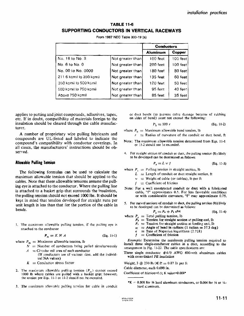
instollation practices
TABLE 11-6
SUPPORTING CONDUCTORS IN VERTICAL RACEWAYS From 1987 NEe Table 300middot19 (a)
Conduelors
Aluminum Copper
No 18 to No B Not greater than 100 feet 100 feet
NO6 to No 0 Not greater than 200 feel 100 feel
No 00 to No 0000 Not greater than 180 feel 80 feet
2116 kernil to 350 kernil Not greater than 135 feet 60 feet
350 kernil to 500 kernil Not greater than 120 feet 50 feet
500 kernil to 750 kernil Not greater than 95 feet 40 feet
Above 750 kernil Not greater than 85 feet 35 feet
applies to potting and joint compounds adhesives tapes etc If in doubt compatibility of materials foreign to the insulation should be cleared through the cable manufacmiddot turer
A number of proprietary wire puUing lubricants and compounds are UL-listed and labeled to indicate the compounds compatibility with conductor coverings In all cases the manufacturers instructions should be obmiddot served
Allowable Pulling Tension
The following formulas can be used to calculate the maximum allowable tension that should be applied to the cables Note that these allowable tensions assume the pullshying eye is attached to the conductor Where the pulling line is attached to a basket grip that surrounds the insulation the pulling tension should not exceed 1000 100 It should be kept in mind that tension developed for straight runs per unit length is less than that for the portion of the cable in bends
L The maximum aJ~owable pulling tension if the pulling eye is aHached to the conductor
(Eq Hmiddotl)
where Pm Maximum allowable tension lb N Number of conductors being pulled simultaneously A Circular mil area of each conductor
(If conductors are of various sizes add the individshyual NA values)
K = Conductor stress factor
2 The maximum allowable pulling tension (Pm) cannot exceed 1000 Ib where cables are pulled with a basket grip however the tension per Eqs 11-1 or 1t-2 should nOL be exceeded
3 The matimum allowable pulling tension for cable in conduit
or duct bends (to prevent cable damage becallse of rubbing on sides of bend) must not exceed the following
Ib = 100 r (Eq Hmiddot2)
where Ptgt = Maximum allowable bend tension Ib r = Radius of curvature of the conduit or duct bend ft
Note The maximum aIIowable tension determined from Eqs 11-1 or 1l~2 should not be exceeded
4 For straight section of conduit or duct the pulling tension (lb) likely to be developed can be determined as follows
P=L w t (Eq Hmiddot3)
where p~ = Pulling tension in straight section Ib L Length of conduit or duct straight section ft 1 = Weight of cable (or cables) lb per ft t = Coefficient of friction
Note For a wen constructed conduit or duct with a lubricated cable f approximates 05 For less favorable conditions or with considerable curvature f may approximate 075
5 For curved sections of conduit or duct the pulling tension (lb) likely to be developed can be determined as follows
Ic =1 + 1 eta CEq 1l-4) where Pc = Total pulling tension Ib
Ps = Tension for straight section at pulling end Ib PI = Tension for straight section at feeding end Ib = Angle of bend in radians (I radian = 573 deg) e = Base of Naperian logarithms (2718) f = Coefficient of friction
Example Determine the maximum pulling tension required to install three single-conductor cables in a duct according to the arrangement in Fig 11-22 The cable specifications are
Three single conductor 40 AWG 600-volt aluminum cables with cross-linked PE insulation
Weight 3 290 IbM It = 087 Ib per ft Cable diameter each 0690 in
Coefficietlt of friction=O5 K valueQOOSshy
middotK 0008 for ~ hard aluminum conductors or 0004 for Y2 or J4II
hard aluminum
iIgtiFfR ~o 5 11-11
covered and insulated aluminum wire and cable
A Condttj~ or Doct Ckan)Ot Brush
B Kellems Grip
C Job Famianed Pulling BlUket
Fig 11middot21 Pulling cable in duct Pulling cable between junction boxes of conduit installations is similar
Using a single pulling eye attached to the three conductors and applyshying Eq 11~1 the maximum allowable pulling tension is
Pm=0008 X 3 X 211600=5078 Ib per Sq IImiddot I For the entire run from pull-box (I) to pull box (6) the tension
increments are as follows Sq
11middot3 At box (2) p == L X w X t == 100 X 087 X 05 == 435 Ib
f 0 05 X 1S71 11-4 At box (3) p == P X e = 435 X e
435 x 2194=954
11middot3 At box (4) P = 954 + (4 X w X tJ == 954 + (SO X 087 X 05) = )J72 Ib
0$ X 1571 114 At box (5) p == 1172 bull = 1172 X 2194 =
257llb
11middot3 At box (6) P 2571 + (4 X w X f) = 2571 + (15 X 087 X 05) = 2637 Ib
The total puning tension of 254 lb is far below the 5080 Ib limitation and the tension at each bend is far below the
11-12
recommendation per Eq 11-2 of 100 x 10 or 1000 lb Study of such examples shows that there is an advantage in puning cables from the pull box or manhole closest to the first bend This aids in reducing tension on the installed cable In this instance if the pull started at box (6) the final tension would be about half the above-found value
For a more complete treatment of cable puning in conshyduit the reader is referred to RC Rifenberg AlEE Tranmiddot sactions Dec 1953
Installing Directly Buried Power Cables
If cable placement can be started Defore sidewalks and other obstructions are installed the plowing-in method usually is the most economical method of burying power cable If soil conditions are unsuitable for plowing the
See also Aluminum Underground Distribution Reference Book
PULL BOX
50
PULL BOX
Fig 11-22 Diagram ocircuit layout to illustrate method of computing pulling tension
use of trenchers back hoes Or manual digging is custoshymary If the soil is rocky it should be screened to prevent cable damage Int is not sufficiently fine to closely cover the cable surface a four-inch thickness of sandy loam placed under and over the cable will improve the heat radiating quality of the soil
Duct Or conduit also should be used under streets or where access by digging to a buried cable is not practicable
Sufficient cable slack should be provided at risers and terminals to permit earth movement that may occur because of conductor thermal expansion frost and also as an allowance for future repair
Boards or slabs placed over the cable for mechanical protection should not be directly in contact with the cable but should be laid on an earth fill over the cable
Depth of burial ranges from about 30 to 48 inches for primary cable and from about 24 to 42 inches for secshyondary cable when buried separately On many systems both primary and secondary cables are buried in the same trench with no separation In many areas the trenches are shared jointly with other utilities notably communishycations-both telephone and television cables Joint use of trenches requires close collaboration on installation schedules but offers substantial economies to the sharing utilities
Initially a separation of one foot was required between primary power and communication cables and many comshypanies still require this separation An amendment to the NESC however permits random-lay (no deliberate separation) installation of communication and power cables in the same trenches with grounded wye power systems operating at voltages not in excess of 22 leV to
installation practices
ground ordelta systems operating at voltages not in excess of 53 kV phase to phase under certain conditions describshyed in NESC Section 35 Article 354 However joint use with very long single-phase primary circuits is not recomshymended because of the inductive pickUp of harmonics by the communication cables from the power cables
Care exercised in handling the cable during installation will help to avoid trouble later for damage sustained by the cable during installation has proved to be a major cause of subsequent cable failure
Many of these precautions have to do with making sure there is no insulation damage The cable is not susceptible to corrosion failure when insulation is unbroken even where moisture has gained entry into the conductor is some manner this fact has been determined in cable manufacshyturer laboratory tests and from research by utilities Migrashytion of moisture through damaged insulation in the presence of ac potential concentrates ions and promotes ac electrolysis
Cable transitions between overhead and underground usually employ the conventional factory-molded pothead of which special types are available for use in URD systems A termination is not reqnired however if the insulated aerial cable is also suitable for direct burial Such a cable can be carried directly down the pole Riser shields or conduit should be used to protect the cable on the riser pole to a point at least eight feet above ground level and should extend at least 12 inches below ground The riser shield must be solidly grounded to the system neutral and bonded to the lightning arrester to avoid transient potentials
Many other practices relating to buried cables and their connection to transformers to service entrances and tap connections in junction boxes and vaults are described in industry manuals Practice is gradually becoming standshyardized in the direction of increasing reliability and lowershying installation and maintenance costs in this most imshyportant segment of power distribution
The following suggestions will help to avoid failures from this cause they apply equally to cable and cable in pipe
1 Make sure that end seals are intact both while the cable is stored and installed to avoid entrance of water into the strands
2 If plowing is not used cables if at all possible should be payed out along the side of the trench from moving reels or carefully laid in the trench from stationary reels
3 The trench should not be dug before final grading is determined so cable will not be exposed or be too close to the surface
bull See also IEEE Conference Record 31C35 Special Technical Conference on Underground Distribution Sept 27~29 1966
11-13
covered and insulated aluminum wire and cable
TABLE 11middot7
I ICEA MINIMUM BENDING RADII FOR POWER CABLES
WlTHOtIT METAlliC SHIELDINGmiddot
I Minimum Bendine RHii as a Multiple of Cable Diameter
I cabl DO Inchbullbull
Tlllcimess of 1000 1001 2001 i
Insulation Inch I and less tD 2000 and OYer
0156 and Ie 4 5 6
I 0157 to 0312 5
i 6
7 0313 and over - 7 S
bull Only applicable for cable training bearing pressure limitation may require larger bending radii for cable tension
Data apply to single and multiple conductor cable also to wire-shielded cable Minimum bending radius for cables with metallic shielding tape is 12 Urnes the completed cable 00 The National Elecshytrical Code Section 300-34 requires 8 times fot non-Shielded and 12 times for shielded medium voltage cable bending radiI
4 In rocky soil areas use screened backfill Or sand to protect direct buried cable A 2-inch bedding is sufficient below but there should be a minimum cover of about 4 inches (The bedding and cover can be omitted when duct in conduit is used)
5 If boards concrete slabs etc are used above the cable for mechanical protection they should not be in direct contact to avoid shearing action when the soil settles Make sure boards are treated with preshyservatives that will not harm the cables insulation
6 Check the cable visually for damage before burial or installation in duct
7 When primaries are pulled into ducts or open trenches the use of a pulling grip over the cable is common rather than a pulling eye or other attachment conshynected directly to the conductor Duct should be carefully cleaned by pulling a plug through it to remove all burrs and obstructions To keep the cableshypulling tension within safe limits a lubricant approved for use with the specific insulation and insulation shield should be used
8 When doing permanent training make sure that the minimum bending radii are observed (see Table 11-7) Make every effort to provide more radius than these values at reel payout risers plow guides duct bend etc
9 Make sure splices and other connections are made in accordance with manufacturers recommendashytions
10 Double check to make sure proper backfilling is done Rock fill should be kept away from the cables to
prevent damage Compacting should be carefully done and air spaces minimized
11 Proof test the cable after installation to insure integshyrity of insulation and splices (See Table 11-8)
12 Dont overfuse the cable Because of the paucity of failures many utilities prefer to use one-shot fuses as an added protective measure for the cable
Many of these precautions have to do with making sure there is nO insulation damage The conductor in 600 volt cables is not susceptible to corrosion failure when insulation is unbroken and moisture has not gained entry into the conductor When moisture enters a break in insulation however ac electrolysis begins
Splicing and Terminating in Underground Systems
The revolution in underground distribution system design has included the devices and methods used for making splices connections and terminations The obshyjective here has been to reduce the amount of skill and time required in the field so as to reduce the installation costs More prefabrication is being done under factoryshycontrolled conditions and the need for heating and pouring of insulating compounds or extensive taping in the field has been greatly reduced
Aluminum connectors and terminating devices should be used with aluminum conductors so as to avoid differshyential thermal expansion and contraction upon heating and cooling that could result from the use of connectors of dissimilar metals Compression type connectors and lugs applied with a tool and die are widely used It is
11-14
instolation practices
TABLE 11middot8
ICEA RECOMMENDED de PRooFmiddotTEST VOLTAGES (15 Minute Test)
Polyethylene or CrossmiddotLinked Polyethylene Insulatd cables
ProofmiddotTestRated Insulation Voltage 1mCircuit Thicllnm (Mils)Voltage Installation
i
25 5001middot 8000 115 2001middot 5000 90
35 8001middot15000 175 55
15001 middot25000 80 25001 middot28000
260 85280
28001middot 35000 345 100
important in installing these devices that a die of the correct size be used and full pressure be applied in order to obtain permanently sound connections
600 Voll Secondary Clrcuils
In this regard connector manufacturers have made important advances in the design of connection devices for secondary circuits There are far too many types to describe them all in this handbook However a couple of examples are given below to indicate the types of premiddot molded splices and terminations that are currently availmiddot able for this type of service
(a) Underground Direct Burial Splice 600 volt insulated cable splices are available for conductor sizes 6 AWG stranded through 1000 kcmil and can be completely installed and sealed without taping or compound filling Typical installation procedure is (Fig 11middot23) as follows
Step A
Lubricate both insulating splice caps by applying a small amount of the supplied lubricant to the inside diameter of the cap at both the housing end and also to the inside diameter at the conductor hole end For easier assembly of the insulating caps to the conshyductor jt is recommended that the insulation at the end of the conductor be penciled before stripping Then place the proper caps over each conductor end
Step B
Strip correct length of conductor insulation for the splice connector being used Place splice housing over end of conductor and assemble one cap to housing Large end of cap should cover the knurled line of the housing body
Step C
Wire brush exposed cable ends and then immediately
insert cables into connector Start crimping splice onto conductor as per manufacturers instructions Continue crimping to ends of splice overlapping crimps 118 inch minimum Wipe away all excess oxide inhibitor
Step D Place housing with the assembled cap over splice connection and snap remaining cap in place on housing to complete the sealed splice When caps are correctly installed the large ends should cover the knurled lines on both ends of the housing body
(b) Secondary 600 V Underground Terminations There are several different designs of connector products which are approved for use in underground 600 V electric power systems They supply the needs of connectors required for residential or commercial use direct burial below grade vaults pedestal or pad mounted equipment bolted or compression fittings and in any combination
Fig 11-24 shows a representative group of these fittings which are designed to accommodate a wide range of conductors Their installation is straightforward and reshyquires no field cutting or hand taping for insulation or environmental sealing The threaded stud connector for transformers is such that the connector can be detached from the transformer without disconnecting the conducmiddot tors
Primary Circuits
Termination of primary underground cables requires some type of stress relief Initially these were made up by taping a stress cone which proved to be one of the most tedious and time-consuming jobs for the field man Today most utilities use some form of preshaped Or prefabricated stress cone which can be installed in a fraction of the time
11-15
-----------
covered and insulated aluminum wire and coble
B IN4fyenSUIATlNGCAP rNO PENCILING
__ bull ( REQUIRED
- -f -- -~I L
c - ~ _shy
D
STRIP os lENGTH
INSUATINi CAP KNURLED LINES
- - - - -HHH+shy~ SPUCE HOUSING
~~~-~~~-$PUCE CONNECTOR INSULATING CAP bull----- E--- KNURLEO
LINES
l__________________________________________________________~c~ou_n_e~~8~la~Ok~b_ria~n~C~O~_J Fig 11middot23 Secondary 600 V Underground Splice Kit showing sequence of assembly steps
Typical terminations for primary cables indicate that molded precut tape and porcelain types are used indoors while porcelain units are most often used outdoors One of the most significant developments in primary cable terminations has been the introduction of plugmiddotin conmiddot nectors for joining the cables to equipment or other cables With these devices it is almost as easy to conncct a primary cable as to plug in or remove an appliance cord from a convenience outlet
11middot16
The concept of premolded stress relief takes the fabshyrication of a stress relief COre away from the field and into the factory with its controlled environment leaving just the assembly to the field installer Elastomeric conshynections form a very convenient inexpensive and reliable method of connecting or terminating high voltage cables Power cable loadbreak elbows in the 35 kV class were introduced to the industry in 1983 with designs for 15 kV and 25 kV following in 1985
installation practices
CAP for porcelain bushings
Set screw s In seu connector are light shyened dow n on flat side 01 Adapter pressure deforms Adapter to lock Ad~pter and seu conneCtor to threaded stud un screws can be b8 C k~d -ofl Adapter and seu conn eCt or removed from transformer without remo ving conductor from connector
Thr eaded Stud Secondary Bush ing
l Adapter Scr6W5 on threaded tud of bllshing Iat side 01 Adapter mUSt be oriented to receive sel Ic rews
seu connector slips o ver Ad apUlr All Adapters have ~
0-ring5 In Sealing Cep same 0 0 all seu con shyseal arond Bushing neclors ho ve seme Adepter Neck and seu connector cavit y 10
Fig -24 Some typical 600 V underground termination fillings
Through the combined efforts of the connector and Some typical applications of premolded products are apparatus manufacturers and the utilities there is availshy at pulling or junction boxes cable to equipment connecshyabte today an array of premolded products that exhibit a tons and cable to cable connections All of these comshyhigh degree of safety reliability and flexibility ponents are designed and tested to be in compliance with
ANSUIEEE Standard 386-1985 Separable Insulated middotSee James W Fitzhughs paper Exploring the Application of Connectors for Power Distribution Systems above 600 Premolded Products for High Voltage Power Systems Volts
11-17
covered and insulated aluminum WIre and cable
Prlo(o counesy 01 ELASTIMQLO
Fig -25 Power cable joint for use af 15 k V or 25 kV
Primal( Voltage Circuits
A cutaway view of an up-to-date power cable j0i nt is shown in Fig 11-25 The cloverleaf design allows the joint to operate at lower temperatures
While installation of premolded devices are si milar conditions may vary depending on the device the cable and the manufacturer of the splice or termination In all cases full instructions will be provided and should be followed Additional typical designs are shown in Fig 11-26
Development work in splicing connecting and tershymina ting devices is still proceeding Users thus are ad vised to keep posted on the latest designs being offered by the connector manufacturers in order to achieve greatest economies in making cable splices connections a nd terminations
Though recent trends have been toward the use of premolded splicing and terminating devices it is still necessary or desirable in some circumstances to make hand-taped joints by traditional methods Because of this the details of making a hand-taped concentric neutral st raight splice are given below Details of the joint are shown in Fig 11 -27
The following are the in struction s to be generally based in making the joint illustrated in Fig 11-27 They are for a typical hand-taped primary cable splice All splices and terminations should be made by a qualified cable splicer in accordance with the manufacturers instructions and recommendations
I Study splice drawing and instructions
2 Train cables into final position and overlap for 18 inches to afford enough excess concentric wire for final jointing
11-18
3 Tem porarily wrap a number of turn s of tape over the outer concentric wires at least 18 inches from the centerline of the splice
4 Carefully unwrap outer concent ric wires and temshyporarily remove them out of the splice area being sure not to damage or kink them
TABLE -9 Recommending Taping Dimensions
Inlull-Ok A B C 0 K
Thkkmiddot u
15KV
175P One- Iall
Connector Zmiddot 4 2A oj- 14~ 38 220 lenglh
25KV
One-tlall 2so Connecl0r 2W 514 2A + 1112 716
length
35KV
One-hall 916~345 7Connector 2A + 22
length 5 Cut off excess cable at splice centerine
6 Remove outer semiconducting jacket for a di stance of (A + I + B + C) inches from each cable making sure th~t the insulation is not damaged during the removal operation All traces of the semiconducting jacket must be removed by a nonconductive abrasive or rasp
7 Remove the insulation from each conductor for a distance of (A + I) inches making sure that the conductor is not nicked during the removal operation
installation practices
Assembly of Tee Splice and Tap Devices
bull Straight Line Splice
Disconnectible Straight Line Splice
Loadbreak Elbow
Connectors
Modular Cable Terminator
Fig 11-26 Some typical primary voltage premolded splicing and terminating devices
11-19
covered and insulated aluminum wire and cable
Splicing-15kV-25kV-35kV Primary Cables-Hand Taped Splice Single conductor with concentriC neutral straight splice (conventional or crossmiddotlinked polyethylene insulated solid or stranded) for grounded neutral service
Concentric Wires TwiSled amp Spliced in Connector
One Hlfmiddotlapped Laye Friction Tape Halfmiddotlapped layer SemlmiddotConducting SelfmiddotFusing Tape
Self-Vulcanizing Tape One Halfmiddotlapped layer 10 K Thickn Tinned Copper Mesh Braid
Two Half-Lapped layers Self-Fusing middotA = OnemiddotHalf Connector lengthRubber-Like Tape
Fig 11middot27 Details ofa taped primary cable joint
Penciling tools will remove the insulation as well as provide smooth penciled surface
8 Apply the required compression connector on each cable following the connector manufacturers recmiddot ommended procedure Note It is recommended that a smooth surface type connector be used--not an indented type If an indented type is used fill the indents with a pliable insulation putty
9 Remove all sharp edges from compressed connector using a file Or heavy abrasive cloth
10 Pencil the ends of the polyethylene insulation for a distance of (B) inches Be sure not to cut into the insulation or damage the conductor during the penshyciling procedure Buff the insulation pencils if they are not smooth with a nonconductive abrasive or rasp This step would be completed with a penciling tool (See Step 7 above)
II Clean all exposed surfaces with a nontoxic and nonflammable solvent and allow to dry Care must be taken in wiping the black conductingjackets since this may smear over the insulation surface
12 Apply one half-lapped layer of semiconducting tape (Bishop Tape No 17 or equivalent) over the exposed conductor and connector Tape should just contact the edge of the cable insulation and be applied with enough tension to conform to the connector
13 Apply halflapped layer of high voltage selfmiddotfusing tape with manufacturers recommended tension starting at connector centerline and building up to the level of be connector in areas between insulation pencil and connector by evenly wrapping tape back and forth across the connector Apply splice tape buildup to a thickness of K inches over the connector and for a longitudinal distance of D inches tapering at the ends
14 Apply one hulf-Iapped layer of selfmiddotfusing semiconshyducting tape over insulating tape buildup extending I inch beyond insulating tape onto be semiconducting jacket on each side of splice The semiconducting tape should be applied with adequate tension
15 Apply one half-lapped layer of tinned copper mesh braid over the semiconducting tape and extend I inch at each end of splice The tinned copper mesh braid
11-20
Insulating Tope
Fflction Tape
Rain Shield
r-h~bj--Insulaling Tope
Melol Grounding Strap
installation practices
should be wrapped as tight as possible and taping should be started at the centerline of tbe splice using two portions of tinned copper mesh braid
16 Apply two solder lines 180 degrees apart for the full length of the mesh braid making sure that the heat does not remian in one spot too long to damage the cable insulation or tapes
17 Tie the concentric outer wires in place using wraps of No 14 AWG tinned or bare copper wire and tack solder in place
18 Apply two half-lapped layers of a self-fusing high voltage tape OVer the outer braid with minimum tension
19 Apply one half-lapped layer of jacket tape over tbe mesb braid to the edge of the concentric wires at each end of the splice
20 Twist the concentric wires together and cut off excess length Place the formed wires into the proper sized mechanical (or compression) connector and splice in place to form low resistance joint following the connector manufacturers recommended procedure
o Insuloling Tope --IO~
Conduclor --+0
Coble Insulolion --1~
Insuloling Tope
Friclion Tope
Rain S~ield
Bios-Cui I nsuloting Tope
Mesh Shielding Braid
Friction Tope
1t1--Stress-Re lie Cone
Coble Shielding Tope --Hic1--J
Jacket
A Single conductor outdoor termination
Terminal Lug
Mesh Shielding Braid
+----Jackel
B 3-Conductor outdoor termination
Terminating Detail
The construction details of secondary or primary cable terminations depend on whether the termination is outshydoor indoor or from underground and wbether it is horizontal for connection to an equipment terminal or vershytical for connection to another conductor Trifurcating assemblies are also used for terminating a three-conductor cable so the urunsulated terminals are well separated (Fig 11-28)
Terminations usually are either of the pothead type or the built-up stress-relief type Both types provide extra insulation close to the actual termination ofthe conductor to provide protection against the extra voltage at these locations
Primarily potheads of plastic insulating materials are used with primary and secondary URD systems altbough porcelain potheads and semi-assembled built-ut sess relief cones (or kits that facilitate tbeir qllick assemt) _e still used for this application (Fig ll-16)
Stress-relief cones are also required in cable splices
Terminal Lug o o
Ilir--Conductor It-lt-Insulang Tope
Fig 11-28 Typical terminations S-lSkV
11-21
covered and insulated aluminum WIre and cable
where there is a change of conductor size the variation of current density in the adjacent conductors creates dielectric stress variations that occur when a cable is terminated
The detailed methods of terminating shielded and nonshyshielded cables closely resemble those used for splicing except that the termination process requires the inclusion of a stress-relief cone or a pothead and if the installation is outdoor and vertical the addition of a rain shield to shed water from the cable insulation is customary Descriptive details are supplied by cable and accessory manufacturers with dimensions for various sizes and voltages The accomshypanying illustrations list the successive operations The precautionary recommendations mentioned in relation to cable splicing also apply to terminating procedure subject
1 TERMINAL CONNECTOR The universal rod connector attaches to the power source
2 MOLDED RUBBER CAP Presses over top of tenninator with an intershyference fit to provide complete wsterseal in~ tegrity
3 RETAINING WASHER Mechanically prevents any cable slippage within terminator
4 TERMINATOR HOUSING Molded of special EPDM compounds lor funcshytional reliability and long life Actual creep distance is 18 (457 em)
5 CABLE INSULATION Primary insulation is provided since cable insulation carries through the terminator
6 INTERFERENCE FIT Molded insulating EPDM exerts unffonn conshycentric pressure on insulation of cable to provide required creepmiddotpatl1 length and washyterseat
7 MOLDED STRESS RELIEF Factory-tested molded stress relief assures proper stress relief for terminating cable A patented Elastimold feature
8 GROUND STRAP Provides a convenient point to connet a ground wire to the molded conductive shield and places the molded shield at ground potential
Courtesy Amerace Corp Elastimold Div
to such changes as appear in manufacturers instructional manuals
The cross-section of a molded terminal connector is shown in Fig 11-29 illustrating the component part ofa connector designed for conductors up to 25 kV It is suitable for uSe on solid dielectric cables and can be applied directly on cables with extruded semi-conductive shields including full neutral concentric It will accomshymodate aluminum conductors in the range of No 6 to 410 AWG with an insulation thickness of 0495 to 1115 Mter proper cable preparation the terminal connector is slid down over the bared cable insulation until it bottoms On the cable shield No special tools or potting compounds are required for the assembly of this type of fitting
Fig 11-29 Typical single conductor molded pothead for cable termination
11-22
Installing Aerial Insulated Cables
Single insulated or covered overhead primary aluminum conductors suspended from insulators sometimes are used in tree areas or similar locations Their installation is simishylar to that of bare conductors as described in Chapter 5 The span lengths usually are moderate so that sag and tension values generally are obtained from tables Howshyever for unusual spans sag-tension charts can be comshyputed or are available from conductor suppliers For aluminum 1350 conductors or less than hard tempers adjustment must be made for reduction of strength
For economic reasons however most overhead spans of insulated power conductors are in the form of preasshysembled or field-assembled multi-conductor cables susshypended from a bare messenger Insulator support is not required and space is saved by using a single-multi-conshyductor cable The conductors may be spiraled around the messenger or arranged paraliel to it as described 10
Chapter 7 Messenger supported cables are in two groups
Preassembled aerial cables (to 35 kV) Aerial cable assemblies (0 to 600 volts)
Primary Aerial Cables
The messenger size for primary cables is determined by the required strength except that for single-phase prishymary circuits (No 2 A WG or smaller) where the messhysenger also serves as a neutral conductor the conductance of the messenger must equal that of the insulated conshyductor Bare messengers not used as neutral conductors are often used also as a part of relaying circuits as a part of the grounding circuit for the insulation shielding and as an auxiliary to a common-neutral For these reasons specifications for multi-conductor primary cables with bare messengers usually specify the ohmic resistance of the messenger The combination of strength and moderate electrical resistance requirements of such non-neutral messhysengers has led to wide acceptance of composites of aluminum and of steel (Alumoweld) for the make-up of the messenger
Messenger sizes are such that the normal initial sagging tension at 60F will not exceed 30 of its rated strength and its maximum tension will not exceed 50 of its rated strength at the fully loaded condition Physical details of the cables used for the messengers listed in Tables 11-10 and II-II can be found in Tables 4-5 (1350-Hl9) 4-12 (6201-T81) and 4-14 (ACSR) These messenger sizes conform to the ICBA recommendation that the initial sag be such that the final sag be not less than 1667 of the span length
Stringing sag and tension charts are supplied by cable manufacturers as an aid to circuit design for light medium or heavy loading conditions (NESC see Table 5-1) for use as described in Chapter 5 However in most instances the spans are of moderate length so suitable sag-tension values may be obtained directly or interpolated from manushy
installation practices
faeturer-supplied tables that Jist initial and final values for 100 125 and 150 ft spans
For the installer of the cable the most useful tabular values are those for initial sag and tension usually for 60degF but a correction factor is applied if the installation temperature differs from 60F The final sag and tension values for the various NESC loading districts then will meet requirements as to the percent that messenger tension bears to its ultimate breaking strength and the manufacshyturers table will confirm this if required The messengers for preassembled primary cables are not neutral conducshytors but high conductance is useful for grounding or signal purposes hence the equivalent conductor rating is usually listed for the messenger For this reason various combinashytions of steel 1350 aluminum and high-strength alloy aluminum are often used for primary aerial messengers
Table 11-10 is extracted from more complete tables in order to show the form in which such tables are supplied Although this table shows use of a combination messenger made of 1350 aluminum strands assembled with strands of aluminum-clad steel other messengers are similarly used of high strength ACSR as well as combinations of 6201 aluminum with steel reinforcement (AACSR)
Fig 11-30 depicts several kinds of fittings and accesshysories used when installing messengers and preassembled aerial cables some of which also apply to preassembled secondary and service-drop cables
Neutral-Supported Secondary and Service-Drop Cables
Preassembled aluminum insulated multi-conductor cables supported by bare neutral messenger conductors have practically become standard for secondary aerial cirshycuits and service drops Subject to the NEC limitation of 300 volts to ground for bare neutrals the triplex form (two insulated conductors preassembled with a bare neushytral) supplies the usual single-phase three-wire circuits Similar quadruplex cables (three insulated conductors) if conneeted to a three-phase Y source supplies low-voltage three-phase loads
The neutral messengers of such cables are selected on basis of strength and conductivity either with conducshytivity equal to that ofa phase conductor or as a reduced neutral having conductivity not less than one-half that of a phase conductor depending on service requirements Tables in Chapter 4 show as mentioned above data regarding bare neutral messengers for such cables Chapshyter 10 describes various types ofcables Fig 11-31 depicts installation details for usual conditions of installation of the secondary cable and the service-drop taps extending from it Initial sag-and-tension data for preassembled triplex aluminum cables with full- and reduced-size neushytrals are in Table 11-11 for the various NESC loadings for 125 ft spans
11-23
3 Bolt Guy Clamp
2 Bott Unieurorsal GUY CHp
Split Bolt Connector
covered and insulated aluminum wire and cable
3 Bolt GUY Clamp
Oval Eye Bolt
Vise Type Connectors
The notation on Table 1I-1I with regard to initial sag values for other spans than 125 ft is based on Eq 5-2 but it is only approximate hence it is available to obtain correct values from the cable manufacturer
The sag-tension values of Table 11-11 are for initial unshyloaded conditions at 60F The sag eventually will inshycrease to the final value and the tension correspondingly will decrease as a result of long-time creep When fully loaded according to NESC values the sag and tension both will increase and as temperature drops to OCF under Heavy-Loading conditions the sag decreases and tension
F
2 Bolt Universal GUY Clip
B
E
Strand Connector
increase~ Thus for 20-20 cable with aluminum-alloy 6201 me nger the initial stringing sag-tension of 13 inshy865 Ib becomes 24 in-1955 Ib (see Chapter 5)
The sag-tension values under conditions of maximum NESC loading are useful for circuit design because they indicate minimum clearances under the cable and also verify that there is the specified margin between actual tension and the rated breaking strength of the messenger However tables imilar to Table H-ll for initial stringing conditions are us~d as a basis for installation which is the subject considered in this chapter
o
c
Fig 11-30 Typical details for supporting and dead-ending cables messengers and guy wires on poles
11-24
installation praclices
A
Prelcftllel
~ A V vv
Insulated Clevs
ToPIt
o
DeltldEno tor EQuol)
1 I
B
I Messger Suspesion CImp
Connector (Before Tpig)
c
Plastic Guard Plastic Guard
Messenger Suspension
Clomp
Fig 11-31 Typical installation details for secondary triplex cables neutral-messenger-supported showing service-drop taps and other details
A-Dead-end at pole shuwing also application of serviceshydrop span clamp
B-Double service-drop taps at service-drop span clamp and messenger suspension clamp at pole
C--Service-drop T tap near pole
Tope or Clip
C(lmp(e$$iO_~h~~Connettor_
I I I Prefarmed Oeoo~End (or EquOI )
D-Clevis support at pole for directional change of less than 45deg
E-Dead-end support at pole for directional change of mOre than 45deg
Notes Compression connections are to be taped even though not so shuwn Poles are to be suitably guyed to resist unbalanced forces Armor rods are used where abraSion is likely See Chapter 5 for additional details of armor rods and the like
11-25
covered and insulated aluminum wire and cable
TABLE 11-10
Representative Values extracted from Tables Supplied by
Cable Manufacturer for Initial Sag-and-Tension Values at
60F suitable for Light or Heavy NESC Districtgt
For Preassembled Primary AerialSmiddotIC Cables with AWAC Messenger
Conductor I Calgtl Span Length in FeetI ISize AWG or Kcmi
I
Messe
ISize
nger
Rated Strength
Assembly (2) Diam
in Weight 100 125 150 Ibltt Satinches (3)
100 i 125 I 150 Tensionmiddotlb (11
5000 Volt Unshielded (Class B concentric stranded aluminum cross-linked polyethylene insulation)
6 3-34 1
20 40 350 500 3middot25 750 2middot215
1000 10-25
UbI 7700
11300 13500 19500
1251 0421 19
1575 1770 2007 2374 2693 3215 3695
0645 I 0827 1100 19 1600 2158 3076 4053
23
23
28 337 428 509 516 780655
662 840 1000 27 1118 1364880
1280 1626 1983 21931726 2675
2461 i 3126 3813 3242 I 4119 5024
15()(J( Volt Shielded Grounded Neutral (Class B concentric stranded aluminum semi-con tape strand shield 0175 in XLPE insulation extruded semimiddotcon PE No 22 AWG copper concentric Mylar tape PVC jacket)
2 3-34 110 40 3middot25 350 10-215 500 750 55650()j307)
1000
7700
11300 19500
26900
2459 1379 19 2618 1606 3006 2215 3504 3075
3789 3696
4575 5039 5_079 6390
23 27
28
27
28
31
1122 11418 1739 1306 1645 2024
1801 2269 2679
2500 3151 3720 3005 3787 4659
4032 5040 6048
5031 J64()()~ 1 Initial tension lS such that the final temiion will not exceed 25 percent of rated strength at 60degF I for
light or Heavy NESC loading districts 2 Includes weight of messenger and binder tape
3 Initial sag is such that final sag approximately conforms to ICEA recommendation of 1667 percent of span length
11-26
instollation practices
TABLE 11-11
Typical Initial Stringing Sag and Tension Values for
Three-Conductor Sell-Supported Polyethylene Service-Drop and
Secondary Cable (Triplexl lor 125 ft span at 60degF
lor Various NESC Loading Districts (see Table 5-1
Note For roughly approximate value for spans of 100 ft and 150 ft multiply the initial sag values for 125 ft span by 064 for l00ft
span and by 145 for 150-ft span retaining the initial tension values for 125 ft span These approximations are less accurate for
the Heavy Loading District More accu rate values for spans other than for 125 ft are obtainable from cable manufacturer
I Neutral
Messenger I NESC Light-Loading
NiSC Medium-Loading
NESC
Heavy-loading Con- I Oistrict District District
ductor Size Rated Size AWG Initial Inital Initial Initial Initial InitialStrellgth r
AWG (or EquivJ Ib Sag Tension Sag Tension Sag Tension
ALUMINUM ALLOY 6201 NEUTRAL MESSENGER
4
2 10
20
4 2
IO 20
1760 2800 4460 5390
8 8 8 8
467 750
1195 1415
10 10 8
10
410 680
1060 1255
16 12 1 I
13
250 553 875 865
ACSR NEUTRAL MESSENGER
6 1190 10 2906 10 305 4 18604 10 445 8 415 2 2 11 5752850 10 660
4380IO10 10 1005 12 865 20 531020 10 1255 12 1070
REDUCED ACSR NEUTRAL MESSENGER
12 350 2 4 6 1190 12 295
4 13 445 13 435 110 2
1860 2850 13 670 14 600
20 3550 13 835 16 730I I ALUMINUM NEUTRAL MESSENGER (Aluminum 1350)
54 44
19 195 19 295 23 410
6 6 560 4 4 881 2 2 1350
10 110 1990
26 91 19 195 17 385 19 485
29 98 11 375 1 I 600 12 840 13 975
34 17 13 14
104 72 49 40
105 330 655 755
23 53
115 230
These jnitial sag-tension values are based on NESC loading limits for REA systems that is loaded tension is not to exceed 5000 of messenger rated strength final stringing tension is not to exceed 251 Of rated strength and initial stringing tension is not to exceed 33~13 Of rated strength
11-27

covered and insulated aluminum wire and cable
A Condttj~ or Doct Ckan)Ot Brush
B Kellems Grip
C Job Famianed Pulling BlUket
Fig 11middot21 Pulling cable in duct Pulling cable between junction boxes of conduit installations is similar
Using a single pulling eye attached to the three conductors and applyshying Eq 11~1 the maximum allowable pulling tension is
Pm=0008 X 3 X 211600=5078 Ib per Sq IImiddot I For the entire run from pull-box (I) to pull box (6) the tension
increments are as follows Sq
11middot3 At box (2) p == L X w X t == 100 X 087 X 05 == 435 Ib
f 0 05 X 1S71 11-4 At box (3) p == P X e = 435 X e
435 x 2194=954
11middot3 At box (4) P = 954 + (4 X w X tJ == 954 + (SO X 087 X 05) = )J72 Ib
0$ X 1571 114 At box (5) p == 1172 bull = 1172 X 2194 =
257llb
11middot3 At box (6) P 2571 + (4 X w X f) = 2571 + (15 X 087 X 05) = 2637 Ib
The total puning tension of 254 lb is far below the 5080 Ib limitation and the tension at each bend is far below the
11-12
recommendation per Eq 11-2 of 100 x 10 or 1000 lb Study of such examples shows that there is an advantage in puning cables from the pull box or manhole closest to the first bend This aids in reducing tension on the installed cable In this instance if the pull started at box (6) the final tension would be about half the above-found value
For a more complete treatment of cable puning in conshyduit the reader is referred to RC Rifenberg AlEE Tranmiddot sactions Dec 1953
Installing Directly Buried Power Cables
If cable placement can be started Defore sidewalks and other obstructions are installed the plowing-in method usually is the most economical method of burying power cable If soil conditions are unsuitable for plowing the
See also Aluminum Underground Distribution Reference Book
PULL BOX
50
PULL BOX
Fig 11-22 Diagram ocircuit layout to illustrate method of computing pulling tension
use of trenchers back hoes Or manual digging is custoshymary If the soil is rocky it should be screened to prevent cable damage Int is not sufficiently fine to closely cover the cable surface a four-inch thickness of sandy loam placed under and over the cable will improve the heat radiating quality of the soil
Duct Or conduit also should be used under streets or where access by digging to a buried cable is not practicable
Sufficient cable slack should be provided at risers and terminals to permit earth movement that may occur because of conductor thermal expansion frost and also as an allowance for future repair
Boards or slabs placed over the cable for mechanical protection should not be directly in contact with the cable but should be laid on an earth fill over the cable
Depth of burial ranges from about 30 to 48 inches for primary cable and from about 24 to 42 inches for secshyondary cable when buried separately On many systems both primary and secondary cables are buried in the same trench with no separation In many areas the trenches are shared jointly with other utilities notably communishycations-both telephone and television cables Joint use of trenches requires close collaboration on installation schedules but offers substantial economies to the sharing utilities
Initially a separation of one foot was required between primary power and communication cables and many comshypanies still require this separation An amendment to the NESC however permits random-lay (no deliberate separation) installation of communication and power cables in the same trenches with grounded wye power systems operating at voltages not in excess of 22 leV to
installation practices
ground ordelta systems operating at voltages not in excess of 53 kV phase to phase under certain conditions describshyed in NESC Section 35 Article 354 However joint use with very long single-phase primary circuits is not recomshymended because of the inductive pickUp of harmonics by the communication cables from the power cables
Care exercised in handling the cable during installation will help to avoid trouble later for damage sustained by the cable during installation has proved to be a major cause of subsequent cable failure
Many of these precautions have to do with making sure there is no insulation damage The cable is not susceptible to corrosion failure when insulation is unbroken even where moisture has gained entry into the conductor is some manner this fact has been determined in cable manufacshyturer laboratory tests and from research by utilities Migrashytion of moisture through damaged insulation in the presence of ac potential concentrates ions and promotes ac electrolysis
Cable transitions between overhead and underground usually employ the conventional factory-molded pothead of which special types are available for use in URD systems A termination is not reqnired however if the insulated aerial cable is also suitable for direct burial Such a cable can be carried directly down the pole Riser shields or conduit should be used to protect the cable on the riser pole to a point at least eight feet above ground level and should extend at least 12 inches below ground The riser shield must be solidly grounded to the system neutral and bonded to the lightning arrester to avoid transient potentials
Many other practices relating to buried cables and their connection to transformers to service entrances and tap connections in junction boxes and vaults are described in industry manuals Practice is gradually becoming standshyardized in the direction of increasing reliability and lowershying installation and maintenance costs in this most imshyportant segment of power distribution
The following suggestions will help to avoid failures from this cause they apply equally to cable and cable in pipe
1 Make sure that end seals are intact both while the cable is stored and installed to avoid entrance of water into the strands
2 If plowing is not used cables if at all possible should be payed out along the side of the trench from moving reels or carefully laid in the trench from stationary reels
3 The trench should not be dug before final grading is determined so cable will not be exposed or be too close to the surface
bull See also IEEE Conference Record 31C35 Special Technical Conference on Underground Distribution Sept 27~29 1966
11-13
covered and insulated aluminum wire and cable
TABLE 11middot7
I ICEA MINIMUM BENDING RADII FOR POWER CABLES
WlTHOtIT METAlliC SHIELDINGmiddot
I Minimum Bendine RHii as a Multiple of Cable Diameter
I cabl DO Inchbullbull
Tlllcimess of 1000 1001 2001 i
Insulation Inch I and less tD 2000 and OYer
0156 and Ie 4 5 6
I 0157 to 0312 5
i 6
7 0313 and over - 7 S
bull Only applicable for cable training bearing pressure limitation may require larger bending radii for cable tension
Data apply to single and multiple conductor cable also to wire-shielded cable Minimum bending radius for cables with metallic shielding tape is 12 Urnes the completed cable 00 The National Elecshytrical Code Section 300-34 requires 8 times fot non-Shielded and 12 times for shielded medium voltage cable bending radiI
4 In rocky soil areas use screened backfill Or sand to protect direct buried cable A 2-inch bedding is sufficient below but there should be a minimum cover of about 4 inches (The bedding and cover can be omitted when duct in conduit is used)
5 If boards concrete slabs etc are used above the cable for mechanical protection they should not be in direct contact to avoid shearing action when the soil settles Make sure boards are treated with preshyservatives that will not harm the cables insulation
6 Check the cable visually for damage before burial or installation in duct
7 When primaries are pulled into ducts or open trenches the use of a pulling grip over the cable is common rather than a pulling eye or other attachment conshynected directly to the conductor Duct should be carefully cleaned by pulling a plug through it to remove all burrs and obstructions To keep the cableshypulling tension within safe limits a lubricant approved for use with the specific insulation and insulation shield should be used
8 When doing permanent training make sure that the minimum bending radii are observed (see Table 11-7) Make every effort to provide more radius than these values at reel payout risers plow guides duct bend etc
9 Make sure splices and other connections are made in accordance with manufacturers recommendashytions
10 Double check to make sure proper backfilling is done Rock fill should be kept away from the cables to
prevent damage Compacting should be carefully done and air spaces minimized
11 Proof test the cable after installation to insure integshyrity of insulation and splices (See Table 11-8)
12 Dont overfuse the cable Because of the paucity of failures many utilities prefer to use one-shot fuses as an added protective measure for the cable
Many of these precautions have to do with making sure there is nO insulation damage The conductor in 600 volt cables is not susceptible to corrosion failure when insulation is unbroken and moisture has not gained entry into the conductor When moisture enters a break in insulation however ac electrolysis begins
Splicing and Terminating in Underground Systems
The revolution in underground distribution system design has included the devices and methods used for making splices connections and terminations The obshyjective here has been to reduce the amount of skill and time required in the field so as to reduce the installation costs More prefabrication is being done under factoryshycontrolled conditions and the need for heating and pouring of insulating compounds or extensive taping in the field has been greatly reduced
Aluminum connectors and terminating devices should be used with aluminum conductors so as to avoid differshyential thermal expansion and contraction upon heating and cooling that could result from the use of connectors of dissimilar metals Compression type connectors and lugs applied with a tool and die are widely used It is
11-14
instolation practices
TABLE 11middot8
ICEA RECOMMENDED de PRooFmiddotTEST VOLTAGES (15 Minute Test)
Polyethylene or CrossmiddotLinked Polyethylene Insulatd cables
ProofmiddotTestRated Insulation Voltage 1mCircuit Thicllnm (Mils)Voltage Installation
i
25 5001middot 8000 115 2001middot 5000 90
35 8001middot15000 175 55
15001 middot25000 80 25001 middot28000
260 85280
28001middot 35000 345 100
important in installing these devices that a die of the correct size be used and full pressure be applied in order to obtain permanently sound connections
600 Voll Secondary Clrcuils
In this regard connector manufacturers have made important advances in the design of connection devices for secondary circuits There are far too many types to describe them all in this handbook However a couple of examples are given below to indicate the types of premiddot molded splices and terminations that are currently availmiddot able for this type of service
(a) Underground Direct Burial Splice 600 volt insulated cable splices are available for conductor sizes 6 AWG stranded through 1000 kcmil and can be completely installed and sealed without taping or compound filling Typical installation procedure is (Fig 11middot23) as follows
Step A
Lubricate both insulating splice caps by applying a small amount of the supplied lubricant to the inside diameter of the cap at both the housing end and also to the inside diameter at the conductor hole end For easier assembly of the insulating caps to the conshyductor jt is recommended that the insulation at the end of the conductor be penciled before stripping Then place the proper caps over each conductor end
Step B
Strip correct length of conductor insulation for the splice connector being used Place splice housing over end of conductor and assemble one cap to housing Large end of cap should cover the knurled line of the housing body
Step C
Wire brush exposed cable ends and then immediately
insert cables into connector Start crimping splice onto conductor as per manufacturers instructions Continue crimping to ends of splice overlapping crimps 118 inch minimum Wipe away all excess oxide inhibitor
Step D Place housing with the assembled cap over splice connection and snap remaining cap in place on housing to complete the sealed splice When caps are correctly installed the large ends should cover the knurled lines on both ends of the housing body
(b) Secondary 600 V Underground Terminations There are several different designs of connector products which are approved for use in underground 600 V electric power systems They supply the needs of connectors required for residential or commercial use direct burial below grade vaults pedestal or pad mounted equipment bolted or compression fittings and in any combination
Fig 11-24 shows a representative group of these fittings which are designed to accommodate a wide range of conductors Their installation is straightforward and reshyquires no field cutting or hand taping for insulation or environmental sealing The threaded stud connector for transformers is such that the connector can be detached from the transformer without disconnecting the conducmiddot tors
Primary Circuits
Termination of primary underground cables requires some type of stress relief Initially these were made up by taping a stress cone which proved to be one of the most tedious and time-consuming jobs for the field man Today most utilities use some form of preshaped Or prefabricated stress cone which can be installed in a fraction of the time
11-15
-----------
covered and insulated aluminum wire and coble
B IN4fyenSUIATlNGCAP rNO PENCILING
__ bull ( REQUIRED
- -f -- -~I L
c - ~ _shy
D
STRIP os lENGTH
INSUATINi CAP KNURLED LINES
- - - - -HHH+shy~ SPUCE HOUSING
~~~-~~~-$PUCE CONNECTOR INSULATING CAP bull----- E--- KNURLEO
LINES
l__________________________________________________________~c~ou_n_e~~8~la~Ok~b_ria~n~C~O~_J Fig 11middot23 Secondary 600 V Underground Splice Kit showing sequence of assembly steps
Typical terminations for primary cables indicate that molded precut tape and porcelain types are used indoors while porcelain units are most often used outdoors One of the most significant developments in primary cable terminations has been the introduction of plugmiddotin conmiddot nectors for joining the cables to equipment or other cables With these devices it is almost as easy to conncct a primary cable as to plug in or remove an appliance cord from a convenience outlet
11middot16
The concept of premolded stress relief takes the fabshyrication of a stress relief COre away from the field and into the factory with its controlled environment leaving just the assembly to the field installer Elastomeric conshynections form a very convenient inexpensive and reliable method of connecting or terminating high voltage cables Power cable loadbreak elbows in the 35 kV class were introduced to the industry in 1983 with designs for 15 kV and 25 kV following in 1985
installation practices
CAP for porcelain bushings
Set screw s In seu connector are light shyened dow n on flat side 01 Adapter pressure deforms Adapter to lock Ad~pter and seu conneCtor to threaded stud un screws can be b8 C k~d -ofl Adapter and seu conn eCt or removed from transformer without remo ving conductor from connector
Thr eaded Stud Secondary Bush ing
l Adapter Scr6W5 on threaded tud of bllshing Iat side 01 Adapter mUSt be oriented to receive sel Ic rews
seu connector slips o ver Ad apUlr All Adapters have ~
0-ring5 In Sealing Cep same 0 0 all seu con shyseal arond Bushing neclors ho ve seme Adepter Neck and seu connector cavit y 10
Fig -24 Some typical 600 V underground termination fillings
Through the combined efforts of the connector and Some typical applications of premolded products are apparatus manufacturers and the utilities there is availshy at pulling or junction boxes cable to equipment connecshyabte today an array of premolded products that exhibit a tons and cable to cable connections All of these comshyhigh degree of safety reliability and flexibility ponents are designed and tested to be in compliance with
ANSUIEEE Standard 386-1985 Separable Insulated middotSee James W Fitzhughs paper Exploring the Application of Connectors for Power Distribution Systems above 600 Premolded Products for High Voltage Power Systems Volts
11-17
covered and insulated aluminum WIre and cable
Prlo(o counesy 01 ELASTIMQLO
Fig -25 Power cable joint for use af 15 k V or 25 kV
Primal( Voltage Circuits
A cutaway view of an up-to-date power cable j0i nt is shown in Fig 11-25 The cloverleaf design allows the joint to operate at lower temperatures
While installation of premolded devices are si milar conditions may vary depending on the device the cable and the manufacturer of the splice or termination In all cases full instructions will be provided and should be followed Additional typical designs are shown in Fig 11-26
Development work in splicing connecting and tershymina ting devices is still proceeding Users thus are ad vised to keep posted on the latest designs being offered by the connector manufacturers in order to achieve greatest economies in making cable splices connections a nd terminations
Though recent trends have been toward the use of premolded splicing and terminating devices it is still necessary or desirable in some circumstances to make hand-taped joints by traditional methods Because of this the details of making a hand-taped concentric neutral st raight splice are given below Details of the joint are shown in Fig 11 -27
The following are the in struction s to be generally based in making the joint illustrated in Fig 11-27 They are for a typical hand-taped primary cable splice All splices and terminations should be made by a qualified cable splicer in accordance with the manufacturers instructions and recommendations
I Study splice drawing and instructions
2 Train cables into final position and overlap for 18 inches to afford enough excess concentric wire for final jointing
11-18
3 Tem porarily wrap a number of turn s of tape over the outer concentric wires at least 18 inches from the centerline of the splice
4 Carefully unwrap outer concent ric wires and temshyporarily remove them out of the splice area being sure not to damage or kink them
TABLE -9 Recommending Taping Dimensions
Inlull-Ok A B C 0 K
Thkkmiddot u
15KV
175P One- Iall
Connector Zmiddot 4 2A oj- 14~ 38 220 lenglh
25KV
One-tlall 2so Connecl0r 2W 514 2A + 1112 716
length
35KV
One-hall 916~345 7Connector 2A + 22
length 5 Cut off excess cable at splice centerine
6 Remove outer semiconducting jacket for a di stance of (A + I + B + C) inches from each cable making sure th~t the insulation is not damaged during the removal operation All traces of the semiconducting jacket must be removed by a nonconductive abrasive or rasp
7 Remove the insulation from each conductor for a distance of (A + I) inches making sure that the conductor is not nicked during the removal operation
installation practices
Assembly of Tee Splice and Tap Devices
bull Straight Line Splice
Disconnectible Straight Line Splice
Loadbreak Elbow
Connectors
Modular Cable Terminator
Fig 11-26 Some typical primary voltage premolded splicing and terminating devices
11-19
covered and insulated aluminum wire and cable
Splicing-15kV-25kV-35kV Primary Cables-Hand Taped Splice Single conductor with concentriC neutral straight splice (conventional or crossmiddotlinked polyethylene insulated solid or stranded) for grounded neutral service
Concentric Wires TwiSled amp Spliced in Connector
One Hlfmiddotlapped Laye Friction Tape Halfmiddotlapped layer SemlmiddotConducting SelfmiddotFusing Tape
Self-Vulcanizing Tape One Halfmiddotlapped layer 10 K Thickn Tinned Copper Mesh Braid
Two Half-Lapped layers Self-Fusing middotA = OnemiddotHalf Connector lengthRubber-Like Tape
Fig 11middot27 Details ofa taped primary cable joint
Penciling tools will remove the insulation as well as provide smooth penciled surface
8 Apply the required compression connector on each cable following the connector manufacturers recmiddot ommended procedure Note It is recommended that a smooth surface type connector be used--not an indented type If an indented type is used fill the indents with a pliable insulation putty
9 Remove all sharp edges from compressed connector using a file Or heavy abrasive cloth
10 Pencil the ends of the polyethylene insulation for a distance of (B) inches Be sure not to cut into the insulation or damage the conductor during the penshyciling procedure Buff the insulation pencils if they are not smooth with a nonconductive abrasive or rasp This step would be completed with a penciling tool (See Step 7 above)
II Clean all exposed surfaces with a nontoxic and nonflammable solvent and allow to dry Care must be taken in wiping the black conductingjackets since this may smear over the insulation surface
12 Apply one half-lapped layer of semiconducting tape (Bishop Tape No 17 or equivalent) over the exposed conductor and connector Tape should just contact the edge of the cable insulation and be applied with enough tension to conform to the connector
13 Apply halflapped layer of high voltage selfmiddotfusing tape with manufacturers recommended tension starting at connector centerline and building up to the level of be connector in areas between insulation pencil and connector by evenly wrapping tape back and forth across the connector Apply splice tape buildup to a thickness of K inches over the connector and for a longitudinal distance of D inches tapering at the ends
14 Apply one hulf-Iapped layer of selfmiddotfusing semiconshyducting tape over insulating tape buildup extending I inch beyond insulating tape onto be semiconducting jacket on each side of splice The semiconducting tape should be applied with adequate tension
15 Apply one half-lapped layer of tinned copper mesh braid over the semiconducting tape and extend I inch at each end of splice The tinned copper mesh braid
11-20
Insulating Tope
Fflction Tape
Rain Shield
r-h~bj--Insulaling Tope
Melol Grounding Strap
installation practices
should be wrapped as tight as possible and taping should be started at the centerline of tbe splice using two portions of tinned copper mesh braid
16 Apply two solder lines 180 degrees apart for the full length of the mesh braid making sure that the heat does not remian in one spot too long to damage the cable insulation or tapes
17 Tie the concentric outer wires in place using wraps of No 14 AWG tinned or bare copper wire and tack solder in place
18 Apply two half-lapped layers of a self-fusing high voltage tape OVer the outer braid with minimum tension
19 Apply one half-lapped layer of jacket tape over tbe mesb braid to the edge of the concentric wires at each end of the splice
20 Twist the concentric wires together and cut off excess length Place the formed wires into the proper sized mechanical (or compression) connector and splice in place to form low resistance joint following the connector manufacturers recommended procedure
o Insuloling Tope --IO~
Conduclor --+0
Coble Insulolion --1~
Insuloling Tope
Friclion Tope
Rain S~ield
Bios-Cui I nsuloting Tope
Mesh Shielding Braid
Friction Tope
1t1--Stress-Re lie Cone
Coble Shielding Tope --Hic1--J
Jacket
A Single conductor outdoor termination
Terminal Lug
Mesh Shielding Braid
+----Jackel
B 3-Conductor outdoor termination
Terminating Detail
The construction details of secondary or primary cable terminations depend on whether the termination is outshydoor indoor or from underground and wbether it is horizontal for connection to an equipment terminal or vershytical for connection to another conductor Trifurcating assemblies are also used for terminating a three-conductor cable so the urunsulated terminals are well separated (Fig 11-28)
Terminations usually are either of the pothead type or the built-up stress-relief type Both types provide extra insulation close to the actual termination ofthe conductor to provide protection against the extra voltage at these locations
Primarily potheads of plastic insulating materials are used with primary and secondary URD systems altbough porcelain potheads and semi-assembled built-ut sess relief cones (or kits that facilitate tbeir qllick assemt) _e still used for this application (Fig ll-16)
Stress-relief cones are also required in cable splices
Terminal Lug o o
Ilir--Conductor It-lt-Insulang Tope
Fig 11-28 Typical terminations S-lSkV
11-21
covered and insulated aluminum WIre and cable
where there is a change of conductor size the variation of current density in the adjacent conductors creates dielectric stress variations that occur when a cable is terminated
The detailed methods of terminating shielded and nonshyshielded cables closely resemble those used for splicing except that the termination process requires the inclusion of a stress-relief cone or a pothead and if the installation is outdoor and vertical the addition of a rain shield to shed water from the cable insulation is customary Descriptive details are supplied by cable and accessory manufacturers with dimensions for various sizes and voltages The accomshypanying illustrations list the successive operations The precautionary recommendations mentioned in relation to cable splicing also apply to terminating procedure subject
1 TERMINAL CONNECTOR The universal rod connector attaches to the power source
2 MOLDED RUBBER CAP Presses over top of tenninator with an intershyference fit to provide complete wsterseal in~ tegrity
3 RETAINING WASHER Mechanically prevents any cable slippage within terminator
4 TERMINATOR HOUSING Molded of special EPDM compounds lor funcshytional reliability and long life Actual creep distance is 18 (457 em)
5 CABLE INSULATION Primary insulation is provided since cable insulation carries through the terminator
6 INTERFERENCE FIT Molded insulating EPDM exerts unffonn conshycentric pressure on insulation of cable to provide required creepmiddotpatl1 length and washyterseat
7 MOLDED STRESS RELIEF Factory-tested molded stress relief assures proper stress relief for terminating cable A patented Elastimold feature
8 GROUND STRAP Provides a convenient point to connet a ground wire to the molded conductive shield and places the molded shield at ground potential
Courtesy Amerace Corp Elastimold Div
to such changes as appear in manufacturers instructional manuals
The cross-section of a molded terminal connector is shown in Fig 11-29 illustrating the component part ofa connector designed for conductors up to 25 kV It is suitable for uSe on solid dielectric cables and can be applied directly on cables with extruded semi-conductive shields including full neutral concentric It will accomshymodate aluminum conductors in the range of No 6 to 410 AWG with an insulation thickness of 0495 to 1115 Mter proper cable preparation the terminal connector is slid down over the bared cable insulation until it bottoms On the cable shield No special tools or potting compounds are required for the assembly of this type of fitting
Fig 11-29 Typical single conductor molded pothead for cable termination
11-22
Installing Aerial Insulated Cables
Single insulated or covered overhead primary aluminum conductors suspended from insulators sometimes are used in tree areas or similar locations Their installation is simishylar to that of bare conductors as described in Chapter 5 The span lengths usually are moderate so that sag and tension values generally are obtained from tables Howshyever for unusual spans sag-tension charts can be comshyputed or are available from conductor suppliers For aluminum 1350 conductors or less than hard tempers adjustment must be made for reduction of strength
For economic reasons however most overhead spans of insulated power conductors are in the form of preasshysembled or field-assembled multi-conductor cables susshypended from a bare messenger Insulator support is not required and space is saved by using a single-multi-conshyductor cable The conductors may be spiraled around the messenger or arranged paraliel to it as described 10
Chapter 7 Messenger supported cables are in two groups
Preassembled aerial cables (to 35 kV) Aerial cable assemblies (0 to 600 volts)
Primary Aerial Cables
The messenger size for primary cables is determined by the required strength except that for single-phase prishymary circuits (No 2 A WG or smaller) where the messhysenger also serves as a neutral conductor the conductance of the messenger must equal that of the insulated conshyductor Bare messengers not used as neutral conductors are often used also as a part of relaying circuits as a part of the grounding circuit for the insulation shielding and as an auxiliary to a common-neutral For these reasons specifications for multi-conductor primary cables with bare messengers usually specify the ohmic resistance of the messenger The combination of strength and moderate electrical resistance requirements of such non-neutral messhysengers has led to wide acceptance of composites of aluminum and of steel (Alumoweld) for the make-up of the messenger
Messenger sizes are such that the normal initial sagging tension at 60F will not exceed 30 of its rated strength and its maximum tension will not exceed 50 of its rated strength at the fully loaded condition Physical details of the cables used for the messengers listed in Tables 11-10 and II-II can be found in Tables 4-5 (1350-Hl9) 4-12 (6201-T81) and 4-14 (ACSR) These messenger sizes conform to the ICBA recommendation that the initial sag be such that the final sag be not less than 1667 of the span length
Stringing sag and tension charts are supplied by cable manufacturers as an aid to circuit design for light medium or heavy loading conditions (NESC see Table 5-1) for use as described in Chapter 5 However in most instances the spans are of moderate length so suitable sag-tension values may be obtained directly or interpolated from manushy
installation practices
faeturer-supplied tables that Jist initial and final values for 100 125 and 150 ft spans
For the installer of the cable the most useful tabular values are those for initial sag and tension usually for 60degF but a correction factor is applied if the installation temperature differs from 60F The final sag and tension values for the various NESC loading districts then will meet requirements as to the percent that messenger tension bears to its ultimate breaking strength and the manufacshyturers table will confirm this if required The messengers for preassembled primary cables are not neutral conducshytors but high conductance is useful for grounding or signal purposes hence the equivalent conductor rating is usually listed for the messenger For this reason various combinashytions of steel 1350 aluminum and high-strength alloy aluminum are often used for primary aerial messengers
Table 11-10 is extracted from more complete tables in order to show the form in which such tables are supplied Although this table shows use of a combination messenger made of 1350 aluminum strands assembled with strands of aluminum-clad steel other messengers are similarly used of high strength ACSR as well as combinations of 6201 aluminum with steel reinforcement (AACSR)
Fig 11-30 depicts several kinds of fittings and accesshysories used when installing messengers and preassembled aerial cables some of which also apply to preassembled secondary and service-drop cables
Neutral-Supported Secondary and Service-Drop Cables
Preassembled aluminum insulated multi-conductor cables supported by bare neutral messenger conductors have practically become standard for secondary aerial cirshycuits and service drops Subject to the NEC limitation of 300 volts to ground for bare neutrals the triplex form (two insulated conductors preassembled with a bare neushytral) supplies the usual single-phase three-wire circuits Similar quadruplex cables (three insulated conductors) if conneeted to a three-phase Y source supplies low-voltage three-phase loads
The neutral messengers of such cables are selected on basis of strength and conductivity either with conducshytivity equal to that ofa phase conductor or as a reduced neutral having conductivity not less than one-half that of a phase conductor depending on service requirements Tables in Chapter 4 show as mentioned above data regarding bare neutral messengers for such cables Chapshyter 10 describes various types ofcables Fig 11-31 depicts installation details for usual conditions of installation of the secondary cable and the service-drop taps extending from it Initial sag-and-tension data for preassembled triplex aluminum cables with full- and reduced-size neushytrals are in Table 11-11 for the various NESC loadings for 125 ft spans
11-23
3 Bolt Guy Clamp
2 Bott Unieurorsal GUY CHp
Split Bolt Connector
covered and insulated aluminum wire and cable
3 Bolt GUY Clamp
Oval Eye Bolt
Vise Type Connectors
The notation on Table 1I-1I with regard to initial sag values for other spans than 125 ft is based on Eq 5-2 but it is only approximate hence it is available to obtain correct values from the cable manufacturer
The sag-tension values of Table 11-11 are for initial unshyloaded conditions at 60F The sag eventually will inshycrease to the final value and the tension correspondingly will decrease as a result of long-time creep When fully loaded according to NESC values the sag and tension both will increase and as temperature drops to OCF under Heavy-Loading conditions the sag decreases and tension
F
2 Bolt Universal GUY Clip
B
E
Strand Connector
increase~ Thus for 20-20 cable with aluminum-alloy 6201 me nger the initial stringing sag-tension of 13 inshy865 Ib becomes 24 in-1955 Ib (see Chapter 5)
The sag-tension values under conditions of maximum NESC loading are useful for circuit design because they indicate minimum clearances under the cable and also verify that there is the specified margin between actual tension and the rated breaking strength of the messenger However tables imilar to Table H-ll for initial stringing conditions are us~d as a basis for installation which is the subject considered in this chapter
o
c
Fig 11-30 Typical details for supporting and dead-ending cables messengers and guy wires on poles
11-24
installation praclices
A
Prelcftllel
~ A V vv
Insulated Clevs
ToPIt
o
DeltldEno tor EQuol)
1 I
B
I Messger Suspesion CImp
Connector (Before Tpig)
c
Plastic Guard Plastic Guard
Messenger Suspension
Clomp
Fig 11-31 Typical installation details for secondary triplex cables neutral-messenger-supported showing service-drop taps and other details
A-Dead-end at pole shuwing also application of serviceshydrop span clamp
B-Double service-drop taps at service-drop span clamp and messenger suspension clamp at pole
C--Service-drop T tap near pole
Tope or Clip
C(lmp(e$$iO_~h~~Connettor_
I I I Prefarmed Oeoo~End (or EquOI )
D-Clevis support at pole for directional change of less than 45deg
E-Dead-end support at pole for directional change of mOre than 45deg
Notes Compression connections are to be taped even though not so shuwn Poles are to be suitably guyed to resist unbalanced forces Armor rods are used where abraSion is likely See Chapter 5 for additional details of armor rods and the like
11-25
covered and insulated aluminum wire and cable
TABLE 11-10
Representative Values extracted from Tables Supplied by
Cable Manufacturer for Initial Sag-and-Tension Values at
60F suitable for Light or Heavy NESC Districtgt
For Preassembled Primary AerialSmiddotIC Cables with AWAC Messenger
Conductor I Calgtl Span Length in FeetI ISize AWG or Kcmi
I
Messe
ISize
nger
Rated Strength
Assembly (2) Diam
in Weight 100 125 150 Ibltt Satinches (3)
100 i 125 I 150 Tensionmiddotlb (11
5000 Volt Unshielded (Class B concentric stranded aluminum cross-linked polyethylene insulation)
6 3-34 1
20 40 350 500 3middot25 750 2middot215
1000 10-25
UbI 7700
11300 13500 19500
1251 0421 19
1575 1770 2007 2374 2693 3215 3695
0645 I 0827 1100 19 1600 2158 3076 4053
23
23
28 337 428 509 516 780655
662 840 1000 27 1118 1364880
1280 1626 1983 21931726 2675
2461 i 3126 3813 3242 I 4119 5024
15()(J( Volt Shielded Grounded Neutral (Class B concentric stranded aluminum semi-con tape strand shield 0175 in XLPE insulation extruded semimiddotcon PE No 22 AWG copper concentric Mylar tape PVC jacket)
2 3-34 110 40 3middot25 350 10-215 500 750 55650()j307)
1000
7700
11300 19500
26900
2459 1379 19 2618 1606 3006 2215 3504 3075
3789 3696
4575 5039 5_079 6390
23 27
28
27
28
31
1122 11418 1739 1306 1645 2024
1801 2269 2679
2500 3151 3720 3005 3787 4659
4032 5040 6048
5031 J64()()~ 1 Initial tension lS such that the final temiion will not exceed 25 percent of rated strength at 60degF I for
light or Heavy NESC loading districts 2 Includes weight of messenger and binder tape
3 Initial sag is such that final sag approximately conforms to ICEA recommendation of 1667 percent of span length
11-26
instollation practices
TABLE 11-11
Typical Initial Stringing Sag and Tension Values for
Three-Conductor Sell-Supported Polyethylene Service-Drop and
Secondary Cable (Triplexl lor 125 ft span at 60degF
lor Various NESC Loading Districts (see Table 5-1
Note For roughly approximate value for spans of 100 ft and 150 ft multiply the initial sag values for 125 ft span by 064 for l00ft
span and by 145 for 150-ft span retaining the initial tension values for 125 ft span These approximations are less accurate for
the Heavy Loading District More accu rate values for spans other than for 125 ft are obtainable from cable manufacturer
I Neutral
Messenger I NESC Light-Loading
NiSC Medium-Loading
NESC
Heavy-loading Con- I Oistrict District District
ductor Size Rated Size AWG Initial Inital Initial Initial Initial InitialStrellgth r
AWG (or EquivJ Ib Sag Tension Sag Tension Sag Tension
ALUMINUM ALLOY 6201 NEUTRAL MESSENGER
4
2 10
20
4 2
IO 20
1760 2800 4460 5390
8 8 8 8
467 750
1195 1415
10 10 8
10
410 680
1060 1255
16 12 1 I
13
250 553 875 865
ACSR NEUTRAL MESSENGER
6 1190 10 2906 10 305 4 18604 10 445 8 415 2 2 11 5752850 10 660
4380IO10 10 1005 12 865 20 531020 10 1255 12 1070
REDUCED ACSR NEUTRAL MESSENGER
12 350 2 4 6 1190 12 295
4 13 445 13 435 110 2
1860 2850 13 670 14 600
20 3550 13 835 16 730I I ALUMINUM NEUTRAL MESSENGER (Aluminum 1350)
54 44
19 195 19 295 23 410
6 6 560 4 4 881 2 2 1350
10 110 1990
26 91 19 195 17 385 19 485
29 98 11 375 1 I 600 12 840 13 975
34 17 13 14
104 72 49 40
105 330 655 755
23 53
115 230
These jnitial sag-tension values are based on NESC loading limits for REA systems that is loaded tension is not to exceed 5000 of messenger rated strength final stringing tension is not to exceed 251 Of rated strength and initial stringing tension is not to exceed 33~13 Of rated strength
11-27

PULL BOX
50
PULL BOX
Fig 11-22 Diagram ocircuit layout to illustrate method of computing pulling tension
use of trenchers back hoes Or manual digging is custoshymary If the soil is rocky it should be screened to prevent cable damage Int is not sufficiently fine to closely cover the cable surface a four-inch thickness of sandy loam placed under and over the cable will improve the heat radiating quality of the soil
Duct Or conduit also should be used under streets or where access by digging to a buried cable is not practicable
Sufficient cable slack should be provided at risers and terminals to permit earth movement that may occur because of conductor thermal expansion frost and also as an allowance for future repair
Boards or slabs placed over the cable for mechanical protection should not be directly in contact with the cable but should be laid on an earth fill over the cable
Depth of burial ranges from about 30 to 48 inches for primary cable and from about 24 to 42 inches for secshyondary cable when buried separately On many systems both primary and secondary cables are buried in the same trench with no separation In many areas the trenches are shared jointly with other utilities notably communishycations-both telephone and television cables Joint use of trenches requires close collaboration on installation schedules but offers substantial economies to the sharing utilities
Initially a separation of one foot was required between primary power and communication cables and many comshypanies still require this separation An amendment to the NESC however permits random-lay (no deliberate separation) installation of communication and power cables in the same trenches with grounded wye power systems operating at voltages not in excess of 22 leV to
installation practices
ground ordelta systems operating at voltages not in excess of 53 kV phase to phase under certain conditions describshyed in NESC Section 35 Article 354 However joint use with very long single-phase primary circuits is not recomshymended because of the inductive pickUp of harmonics by the communication cables from the power cables
Care exercised in handling the cable during installation will help to avoid trouble later for damage sustained by the cable during installation has proved to be a major cause of subsequent cable failure
Many of these precautions have to do with making sure there is no insulation damage The cable is not susceptible to corrosion failure when insulation is unbroken even where moisture has gained entry into the conductor is some manner this fact has been determined in cable manufacshyturer laboratory tests and from research by utilities Migrashytion of moisture through damaged insulation in the presence of ac potential concentrates ions and promotes ac electrolysis
Cable transitions between overhead and underground usually employ the conventional factory-molded pothead of which special types are available for use in URD systems A termination is not reqnired however if the insulated aerial cable is also suitable for direct burial Such a cable can be carried directly down the pole Riser shields or conduit should be used to protect the cable on the riser pole to a point at least eight feet above ground level and should extend at least 12 inches below ground The riser shield must be solidly grounded to the system neutral and bonded to the lightning arrester to avoid transient potentials
Many other practices relating to buried cables and their connection to transformers to service entrances and tap connections in junction boxes and vaults are described in industry manuals Practice is gradually becoming standshyardized in the direction of increasing reliability and lowershying installation and maintenance costs in this most imshyportant segment of power distribution
The following suggestions will help to avoid failures from this cause they apply equally to cable and cable in pipe
1 Make sure that end seals are intact both while the cable is stored and installed to avoid entrance of water into the strands
2 If plowing is not used cables if at all possible should be payed out along the side of the trench from moving reels or carefully laid in the trench from stationary reels
3 The trench should not be dug before final grading is determined so cable will not be exposed or be too close to the surface
bull See also IEEE Conference Record 31C35 Special Technical Conference on Underground Distribution Sept 27~29 1966
11-13
covered and insulated aluminum wire and cable
TABLE 11middot7
I ICEA MINIMUM BENDING RADII FOR POWER CABLES
WlTHOtIT METAlliC SHIELDINGmiddot
I Minimum Bendine RHii as a Multiple of Cable Diameter
I cabl DO Inchbullbull
Tlllcimess of 1000 1001 2001 i
Insulation Inch I and less tD 2000 and OYer
0156 and Ie 4 5 6
I 0157 to 0312 5
i 6
7 0313 and over - 7 S
bull Only applicable for cable training bearing pressure limitation may require larger bending radii for cable tension
Data apply to single and multiple conductor cable also to wire-shielded cable Minimum bending radius for cables with metallic shielding tape is 12 Urnes the completed cable 00 The National Elecshytrical Code Section 300-34 requires 8 times fot non-Shielded and 12 times for shielded medium voltage cable bending radiI
4 In rocky soil areas use screened backfill Or sand to protect direct buried cable A 2-inch bedding is sufficient below but there should be a minimum cover of about 4 inches (The bedding and cover can be omitted when duct in conduit is used)
5 If boards concrete slabs etc are used above the cable for mechanical protection they should not be in direct contact to avoid shearing action when the soil settles Make sure boards are treated with preshyservatives that will not harm the cables insulation
6 Check the cable visually for damage before burial or installation in duct
7 When primaries are pulled into ducts or open trenches the use of a pulling grip over the cable is common rather than a pulling eye or other attachment conshynected directly to the conductor Duct should be carefully cleaned by pulling a plug through it to remove all burrs and obstructions To keep the cableshypulling tension within safe limits a lubricant approved for use with the specific insulation and insulation shield should be used
8 When doing permanent training make sure that the minimum bending radii are observed (see Table 11-7) Make every effort to provide more radius than these values at reel payout risers plow guides duct bend etc
9 Make sure splices and other connections are made in accordance with manufacturers recommendashytions
10 Double check to make sure proper backfilling is done Rock fill should be kept away from the cables to
prevent damage Compacting should be carefully done and air spaces minimized
11 Proof test the cable after installation to insure integshyrity of insulation and splices (See Table 11-8)
12 Dont overfuse the cable Because of the paucity of failures many utilities prefer to use one-shot fuses as an added protective measure for the cable
Many of these precautions have to do with making sure there is nO insulation damage The conductor in 600 volt cables is not susceptible to corrosion failure when insulation is unbroken and moisture has not gained entry into the conductor When moisture enters a break in insulation however ac electrolysis begins
Splicing and Terminating in Underground Systems
The revolution in underground distribution system design has included the devices and methods used for making splices connections and terminations The obshyjective here has been to reduce the amount of skill and time required in the field so as to reduce the installation costs More prefabrication is being done under factoryshycontrolled conditions and the need for heating and pouring of insulating compounds or extensive taping in the field has been greatly reduced
Aluminum connectors and terminating devices should be used with aluminum conductors so as to avoid differshyential thermal expansion and contraction upon heating and cooling that could result from the use of connectors of dissimilar metals Compression type connectors and lugs applied with a tool and die are widely used It is
11-14
instolation practices
TABLE 11middot8
ICEA RECOMMENDED de PRooFmiddotTEST VOLTAGES (15 Minute Test)
Polyethylene or CrossmiddotLinked Polyethylene Insulatd cables
ProofmiddotTestRated Insulation Voltage 1mCircuit Thicllnm (Mils)Voltage Installation
i
25 5001middot 8000 115 2001middot 5000 90
35 8001middot15000 175 55
15001 middot25000 80 25001 middot28000
260 85280
28001middot 35000 345 100
important in installing these devices that a die of the correct size be used and full pressure be applied in order to obtain permanently sound connections
600 Voll Secondary Clrcuils
In this regard connector manufacturers have made important advances in the design of connection devices for secondary circuits There are far too many types to describe them all in this handbook However a couple of examples are given below to indicate the types of premiddot molded splices and terminations that are currently availmiddot able for this type of service
(a) Underground Direct Burial Splice 600 volt insulated cable splices are available for conductor sizes 6 AWG stranded through 1000 kcmil and can be completely installed and sealed without taping or compound filling Typical installation procedure is (Fig 11middot23) as follows
Step A
Lubricate both insulating splice caps by applying a small amount of the supplied lubricant to the inside diameter of the cap at both the housing end and also to the inside diameter at the conductor hole end For easier assembly of the insulating caps to the conshyductor jt is recommended that the insulation at the end of the conductor be penciled before stripping Then place the proper caps over each conductor end
Step B
Strip correct length of conductor insulation for the splice connector being used Place splice housing over end of conductor and assemble one cap to housing Large end of cap should cover the knurled line of the housing body
Step C
Wire brush exposed cable ends and then immediately
insert cables into connector Start crimping splice onto conductor as per manufacturers instructions Continue crimping to ends of splice overlapping crimps 118 inch minimum Wipe away all excess oxide inhibitor
Step D Place housing with the assembled cap over splice connection and snap remaining cap in place on housing to complete the sealed splice When caps are correctly installed the large ends should cover the knurled lines on both ends of the housing body
(b) Secondary 600 V Underground Terminations There are several different designs of connector products which are approved for use in underground 600 V electric power systems They supply the needs of connectors required for residential or commercial use direct burial below grade vaults pedestal or pad mounted equipment bolted or compression fittings and in any combination
Fig 11-24 shows a representative group of these fittings which are designed to accommodate a wide range of conductors Their installation is straightforward and reshyquires no field cutting or hand taping for insulation or environmental sealing The threaded stud connector for transformers is such that the connector can be detached from the transformer without disconnecting the conducmiddot tors
Primary Circuits
Termination of primary underground cables requires some type of stress relief Initially these were made up by taping a stress cone which proved to be one of the most tedious and time-consuming jobs for the field man Today most utilities use some form of preshaped Or prefabricated stress cone which can be installed in a fraction of the time
11-15
-----------
covered and insulated aluminum wire and coble
B IN4fyenSUIATlNGCAP rNO PENCILING
__ bull ( REQUIRED
- -f -- -~I L
c - ~ _shy
D
STRIP os lENGTH
INSUATINi CAP KNURLED LINES
- - - - -HHH+shy~ SPUCE HOUSING
~~~-~~~-$PUCE CONNECTOR INSULATING CAP bull----- E--- KNURLEO
LINES
l__________________________________________________________~c~ou_n_e~~8~la~Ok~b_ria~n~C~O~_J Fig 11middot23 Secondary 600 V Underground Splice Kit showing sequence of assembly steps
Typical terminations for primary cables indicate that molded precut tape and porcelain types are used indoors while porcelain units are most often used outdoors One of the most significant developments in primary cable terminations has been the introduction of plugmiddotin conmiddot nectors for joining the cables to equipment or other cables With these devices it is almost as easy to conncct a primary cable as to plug in or remove an appliance cord from a convenience outlet
11middot16
The concept of premolded stress relief takes the fabshyrication of a stress relief COre away from the field and into the factory with its controlled environment leaving just the assembly to the field installer Elastomeric conshynections form a very convenient inexpensive and reliable method of connecting or terminating high voltage cables Power cable loadbreak elbows in the 35 kV class were introduced to the industry in 1983 with designs for 15 kV and 25 kV following in 1985
installation practices
CAP for porcelain bushings
Set screw s In seu connector are light shyened dow n on flat side 01 Adapter pressure deforms Adapter to lock Ad~pter and seu conneCtor to threaded stud un screws can be b8 C k~d -ofl Adapter and seu conn eCt or removed from transformer without remo ving conductor from connector
Thr eaded Stud Secondary Bush ing
l Adapter Scr6W5 on threaded tud of bllshing Iat side 01 Adapter mUSt be oriented to receive sel Ic rews
seu connector slips o ver Ad apUlr All Adapters have ~
0-ring5 In Sealing Cep same 0 0 all seu con shyseal arond Bushing neclors ho ve seme Adepter Neck and seu connector cavit y 10
Fig -24 Some typical 600 V underground termination fillings
Through the combined efforts of the connector and Some typical applications of premolded products are apparatus manufacturers and the utilities there is availshy at pulling or junction boxes cable to equipment connecshyabte today an array of premolded products that exhibit a tons and cable to cable connections All of these comshyhigh degree of safety reliability and flexibility ponents are designed and tested to be in compliance with
ANSUIEEE Standard 386-1985 Separable Insulated middotSee James W Fitzhughs paper Exploring the Application of Connectors for Power Distribution Systems above 600 Premolded Products for High Voltage Power Systems Volts
11-17
covered and insulated aluminum WIre and cable
Prlo(o counesy 01 ELASTIMQLO
Fig -25 Power cable joint for use af 15 k V or 25 kV
Primal( Voltage Circuits
A cutaway view of an up-to-date power cable j0i nt is shown in Fig 11-25 The cloverleaf design allows the joint to operate at lower temperatures
While installation of premolded devices are si milar conditions may vary depending on the device the cable and the manufacturer of the splice or termination In all cases full instructions will be provided and should be followed Additional typical designs are shown in Fig 11-26
Development work in splicing connecting and tershymina ting devices is still proceeding Users thus are ad vised to keep posted on the latest designs being offered by the connector manufacturers in order to achieve greatest economies in making cable splices connections a nd terminations
Though recent trends have been toward the use of premolded splicing and terminating devices it is still necessary or desirable in some circumstances to make hand-taped joints by traditional methods Because of this the details of making a hand-taped concentric neutral st raight splice are given below Details of the joint are shown in Fig 11 -27
The following are the in struction s to be generally based in making the joint illustrated in Fig 11-27 They are for a typical hand-taped primary cable splice All splices and terminations should be made by a qualified cable splicer in accordance with the manufacturers instructions and recommendations
I Study splice drawing and instructions
2 Train cables into final position and overlap for 18 inches to afford enough excess concentric wire for final jointing
11-18
3 Tem porarily wrap a number of turn s of tape over the outer concentric wires at least 18 inches from the centerline of the splice
4 Carefully unwrap outer concent ric wires and temshyporarily remove them out of the splice area being sure not to damage or kink them
TABLE -9 Recommending Taping Dimensions
Inlull-Ok A B C 0 K
Thkkmiddot u
15KV
175P One- Iall
Connector Zmiddot 4 2A oj- 14~ 38 220 lenglh
25KV
One-tlall 2so Connecl0r 2W 514 2A + 1112 716
length
35KV
One-hall 916~345 7Connector 2A + 22
length 5 Cut off excess cable at splice centerine
6 Remove outer semiconducting jacket for a di stance of (A + I + B + C) inches from each cable making sure th~t the insulation is not damaged during the removal operation All traces of the semiconducting jacket must be removed by a nonconductive abrasive or rasp
7 Remove the insulation from each conductor for a distance of (A + I) inches making sure that the conductor is not nicked during the removal operation
installation practices
Assembly of Tee Splice and Tap Devices
bull Straight Line Splice
Disconnectible Straight Line Splice
Loadbreak Elbow
Connectors
Modular Cable Terminator
Fig 11-26 Some typical primary voltage premolded splicing and terminating devices
11-19
covered and insulated aluminum wire and cable
Splicing-15kV-25kV-35kV Primary Cables-Hand Taped Splice Single conductor with concentriC neutral straight splice (conventional or crossmiddotlinked polyethylene insulated solid or stranded) for grounded neutral service
Concentric Wires TwiSled amp Spliced in Connector
One Hlfmiddotlapped Laye Friction Tape Halfmiddotlapped layer SemlmiddotConducting SelfmiddotFusing Tape
Self-Vulcanizing Tape One Halfmiddotlapped layer 10 K Thickn Tinned Copper Mesh Braid
Two Half-Lapped layers Self-Fusing middotA = OnemiddotHalf Connector lengthRubber-Like Tape
Fig 11middot27 Details ofa taped primary cable joint
Penciling tools will remove the insulation as well as provide smooth penciled surface
8 Apply the required compression connector on each cable following the connector manufacturers recmiddot ommended procedure Note It is recommended that a smooth surface type connector be used--not an indented type If an indented type is used fill the indents with a pliable insulation putty
9 Remove all sharp edges from compressed connector using a file Or heavy abrasive cloth
10 Pencil the ends of the polyethylene insulation for a distance of (B) inches Be sure not to cut into the insulation or damage the conductor during the penshyciling procedure Buff the insulation pencils if they are not smooth with a nonconductive abrasive or rasp This step would be completed with a penciling tool (See Step 7 above)
II Clean all exposed surfaces with a nontoxic and nonflammable solvent and allow to dry Care must be taken in wiping the black conductingjackets since this may smear over the insulation surface
12 Apply one half-lapped layer of semiconducting tape (Bishop Tape No 17 or equivalent) over the exposed conductor and connector Tape should just contact the edge of the cable insulation and be applied with enough tension to conform to the connector
13 Apply halflapped layer of high voltage selfmiddotfusing tape with manufacturers recommended tension starting at connector centerline and building up to the level of be connector in areas between insulation pencil and connector by evenly wrapping tape back and forth across the connector Apply splice tape buildup to a thickness of K inches over the connector and for a longitudinal distance of D inches tapering at the ends
14 Apply one hulf-Iapped layer of selfmiddotfusing semiconshyducting tape over insulating tape buildup extending I inch beyond insulating tape onto be semiconducting jacket on each side of splice The semiconducting tape should be applied with adequate tension
15 Apply one half-lapped layer of tinned copper mesh braid over the semiconducting tape and extend I inch at each end of splice The tinned copper mesh braid
11-20
Insulating Tope
Fflction Tape
Rain Shield
r-h~bj--Insulaling Tope
Melol Grounding Strap
installation practices
should be wrapped as tight as possible and taping should be started at the centerline of tbe splice using two portions of tinned copper mesh braid
16 Apply two solder lines 180 degrees apart for the full length of the mesh braid making sure that the heat does not remian in one spot too long to damage the cable insulation or tapes
17 Tie the concentric outer wires in place using wraps of No 14 AWG tinned or bare copper wire and tack solder in place
18 Apply two half-lapped layers of a self-fusing high voltage tape OVer the outer braid with minimum tension
19 Apply one half-lapped layer of jacket tape over tbe mesb braid to the edge of the concentric wires at each end of the splice
20 Twist the concentric wires together and cut off excess length Place the formed wires into the proper sized mechanical (or compression) connector and splice in place to form low resistance joint following the connector manufacturers recommended procedure
o Insuloling Tope --IO~
Conduclor --+0
Coble Insulolion --1~
Insuloling Tope
Friclion Tope
Rain S~ield
Bios-Cui I nsuloting Tope
Mesh Shielding Braid
Friction Tope
1t1--Stress-Re lie Cone
Coble Shielding Tope --Hic1--J
Jacket
A Single conductor outdoor termination
Terminal Lug
Mesh Shielding Braid
+----Jackel
B 3-Conductor outdoor termination
Terminating Detail
The construction details of secondary or primary cable terminations depend on whether the termination is outshydoor indoor or from underground and wbether it is horizontal for connection to an equipment terminal or vershytical for connection to another conductor Trifurcating assemblies are also used for terminating a three-conductor cable so the urunsulated terminals are well separated (Fig 11-28)
Terminations usually are either of the pothead type or the built-up stress-relief type Both types provide extra insulation close to the actual termination ofthe conductor to provide protection against the extra voltage at these locations
Primarily potheads of plastic insulating materials are used with primary and secondary URD systems altbough porcelain potheads and semi-assembled built-ut sess relief cones (or kits that facilitate tbeir qllick assemt) _e still used for this application (Fig ll-16)
Stress-relief cones are also required in cable splices
Terminal Lug o o
Ilir--Conductor It-lt-Insulang Tope
Fig 11-28 Typical terminations S-lSkV
11-21
covered and insulated aluminum WIre and cable
where there is a change of conductor size the variation of current density in the adjacent conductors creates dielectric stress variations that occur when a cable is terminated
The detailed methods of terminating shielded and nonshyshielded cables closely resemble those used for splicing except that the termination process requires the inclusion of a stress-relief cone or a pothead and if the installation is outdoor and vertical the addition of a rain shield to shed water from the cable insulation is customary Descriptive details are supplied by cable and accessory manufacturers with dimensions for various sizes and voltages The accomshypanying illustrations list the successive operations The precautionary recommendations mentioned in relation to cable splicing also apply to terminating procedure subject
1 TERMINAL CONNECTOR The universal rod connector attaches to the power source
2 MOLDED RUBBER CAP Presses over top of tenninator with an intershyference fit to provide complete wsterseal in~ tegrity
3 RETAINING WASHER Mechanically prevents any cable slippage within terminator
4 TERMINATOR HOUSING Molded of special EPDM compounds lor funcshytional reliability and long life Actual creep distance is 18 (457 em)
5 CABLE INSULATION Primary insulation is provided since cable insulation carries through the terminator
6 INTERFERENCE FIT Molded insulating EPDM exerts unffonn conshycentric pressure on insulation of cable to provide required creepmiddotpatl1 length and washyterseat
7 MOLDED STRESS RELIEF Factory-tested molded stress relief assures proper stress relief for terminating cable A patented Elastimold feature
8 GROUND STRAP Provides a convenient point to connet a ground wire to the molded conductive shield and places the molded shield at ground potential
Courtesy Amerace Corp Elastimold Div
to such changes as appear in manufacturers instructional manuals
The cross-section of a molded terminal connector is shown in Fig 11-29 illustrating the component part ofa connector designed for conductors up to 25 kV It is suitable for uSe on solid dielectric cables and can be applied directly on cables with extruded semi-conductive shields including full neutral concentric It will accomshymodate aluminum conductors in the range of No 6 to 410 AWG with an insulation thickness of 0495 to 1115 Mter proper cable preparation the terminal connector is slid down over the bared cable insulation until it bottoms On the cable shield No special tools or potting compounds are required for the assembly of this type of fitting
Fig 11-29 Typical single conductor molded pothead for cable termination
11-22
Installing Aerial Insulated Cables
Single insulated or covered overhead primary aluminum conductors suspended from insulators sometimes are used in tree areas or similar locations Their installation is simishylar to that of bare conductors as described in Chapter 5 The span lengths usually are moderate so that sag and tension values generally are obtained from tables Howshyever for unusual spans sag-tension charts can be comshyputed or are available from conductor suppliers For aluminum 1350 conductors or less than hard tempers adjustment must be made for reduction of strength
For economic reasons however most overhead spans of insulated power conductors are in the form of preasshysembled or field-assembled multi-conductor cables susshypended from a bare messenger Insulator support is not required and space is saved by using a single-multi-conshyductor cable The conductors may be spiraled around the messenger or arranged paraliel to it as described 10
Chapter 7 Messenger supported cables are in two groups
Preassembled aerial cables (to 35 kV) Aerial cable assemblies (0 to 600 volts)
Primary Aerial Cables
The messenger size for primary cables is determined by the required strength except that for single-phase prishymary circuits (No 2 A WG or smaller) where the messhysenger also serves as a neutral conductor the conductance of the messenger must equal that of the insulated conshyductor Bare messengers not used as neutral conductors are often used also as a part of relaying circuits as a part of the grounding circuit for the insulation shielding and as an auxiliary to a common-neutral For these reasons specifications for multi-conductor primary cables with bare messengers usually specify the ohmic resistance of the messenger The combination of strength and moderate electrical resistance requirements of such non-neutral messhysengers has led to wide acceptance of composites of aluminum and of steel (Alumoweld) for the make-up of the messenger
Messenger sizes are such that the normal initial sagging tension at 60F will not exceed 30 of its rated strength and its maximum tension will not exceed 50 of its rated strength at the fully loaded condition Physical details of the cables used for the messengers listed in Tables 11-10 and II-II can be found in Tables 4-5 (1350-Hl9) 4-12 (6201-T81) and 4-14 (ACSR) These messenger sizes conform to the ICBA recommendation that the initial sag be such that the final sag be not less than 1667 of the span length
Stringing sag and tension charts are supplied by cable manufacturers as an aid to circuit design for light medium or heavy loading conditions (NESC see Table 5-1) for use as described in Chapter 5 However in most instances the spans are of moderate length so suitable sag-tension values may be obtained directly or interpolated from manushy
installation practices
faeturer-supplied tables that Jist initial and final values for 100 125 and 150 ft spans
For the installer of the cable the most useful tabular values are those for initial sag and tension usually for 60degF but a correction factor is applied if the installation temperature differs from 60F The final sag and tension values for the various NESC loading districts then will meet requirements as to the percent that messenger tension bears to its ultimate breaking strength and the manufacshyturers table will confirm this if required The messengers for preassembled primary cables are not neutral conducshytors but high conductance is useful for grounding or signal purposes hence the equivalent conductor rating is usually listed for the messenger For this reason various combinashytions of steel 1350 aluminum and high-strength alloy aluminum are often used for primary aerial messengers
Table 11-10 is extracted from more complete tables in order to show the form in which such tables are supplied Although this table shows use of a combination messenger made of 1350 aluminum strands assembled with strands of aluminum-clad steel other messengers are similarly used of high strength ACSR as well as combinations of 6201 aluminum with steel reinforcement (AACSR)
Fig 11-30 depicts several kinds of fittings and accesshysories used when installing messengers and preassembled aerial cables some of which also apply to preassembled secondary and service-drop cables
Neutral-Supported Secondary and Service-Drop Cables
Preassembled aluminum insulated multi-conductor cables supported by bare neutral messenger conductors have practically become standard for secondary aerial cirshycuits and service drops Subject to the NEC limitation of 300 volts to ground for bare neutrals the triplex form (two insulated conductors preassembled with a bare neushytral) supplies the usual single-phase three-wire circuits Similar quadruplex cables (three insulated conductors) if conneeted to a three-phase Y source supplies low-voltage three-phase loads
The neutral messengers of such cables are selected on basis of strength and conductivity either with conducshytivity equal to that ofa phase conductor or as a reduced neutral having conductivity not less than one-half that of a phase conductor depending on service requirements Tables in Chapter 4 show as mentioned above data regarding bare neutral messengers for such cables Chapshyter 10 describes various types ofcables Fig 11-31 depicts installation details for usual conditions of installation of the secondary cable and the service-drop taps extending from it Initial sag-and-tension data for preassembled triplex aluminum cables with full- and reduced-size neushytrals are in Table 11-11 for the various NESC loadings for 125 ft spans
11-23
3 Bolt Guy Clamp
2 Bott Unieurorsal GUY CHp
Split Bolt Connector
covered and insulated aluminum wire and cable
3 Bolt GUY Clamp
Oval Eye Bolt
Vise Type Connectors
The notation on Table 1I-1I with regard to initial sag values for other spans than 125 ft is based on Eq 5-2 but it is only approximate hence it is available to obtain correct values from the cable manufacturer
The sag-tension values of Table 11-11 are for initial unshyloaded conditions at 60F The sag eventually will inshycrease to the final value and the tension correspondingly will decrease as a result of long-time creep When fully loaded according to NESC values the sag and tension both will increase and as temperature drops to OCF under Heavy-Loading conditions the sag decreases and tension
F
2 Bolt Universal GUY Clip
B
E
Strand Connector
increase~ Thus for 20-20 cable with aluminum-alloy 6201 me nger the initial stringing sag-tension of 13 inshy865 Ib becomes 24 in-1955 Ib (see Chapter 5)
The sag-tension values under conditions of maximum NESC loading are useful for circuit design because they indicate minimum clearances under the cable and also verify that there is the specified margin between actual tension and the rated breaking strength of the messenger However tables imilar to Table H-ll for initial stringing conditions are us~d as a basis for installation which is the subject considered in this chapter
o
c
Fig 11-30 Typical details for supporting and dead-ending cables messengers and guy wires on poles
11-24
installation praclices
A
Prelcftllel
~ A V vv
Insulated Clevs
ToPIt
o
DeltldEno tor EQuol)
1 I
B
I Messger Suspesion CImp
Connector (Before Tpig)
c
Plastic Guard Plastic Guard
Messenger Suspension
Clomp
Fig 11-31 Typical installation details for secondary triplex cables neutral-messenger-supported showing service-drop taps and other details
A-Dead-end at pole shuwing also application of serviceshydrop span clamp
B-Double service-drop taps at service-drop span clamp and messenger suspension clamp at pole
C--Service-drop T tap near pole
Tope or Clip
C(lmp(e$$iO_~h~~Connettor_
I I I Prefarmed Oeoo~End (or EquOI )
D-Clevis support at pole for directional change of less than 45deg
E-Dead-end support at pole for directional change of mOre than 45deg
Notes Compression connections are to be taped even though not so shuwn Poles are to be suitably guyed to resist unbalanced forces Armor rods are used where abraSion is likely See Chapter 5 for additional details of armor rods and the like
11-25
covered and insulated aluminum wire and cable
TABLE 11-10
Representative Values extracted from Tables Supplied by
Cable Manufacturer for Initial Sag-and-Tension Values at
60F suitable for Light or Heavy NESC Districtgt
For Preassembled Primary AerialSmiddotIC Cables with AWAC Messenger
Conductor I Calgtl Span Length in FeetI ISize AWG or Kcmi
I
Messe
ISize
nger
Rated Strength
Assembly (2) Diam
in Weight 100 125 150 Ibltt Satinches (3)
100 i 125 I 150 Tensionmiddotlb (11
5000 Volt Unshielded (Class B concentric stranded aluminum cross-linked polyethylene insulation)
6 3-34 1
20 40 350 500 3middot25 750 2middot215
1000 10-25
UbI 7700
11300 13500 19500
1251 0421 19
1575 1770 2007 2374 2693 3215 3695
0645 I 0827 1100 19 1600 2158 3076 4053
23
23
28 337 428 509 516 780655
662 840 1000 27 1118 1364880
1280 1626 1983 21931726 2675
2461 i 3126 3813 3242 I 4119 5024
15()(J( Volt Shielded Grounded Neutral (Class B concentric stranded aluminum semi-con tape strand shield 0175 in XLPE insulation extruded semimiddotcon PE No 22 AWG copper concentric Mylar tape PVC jacket)
2 3-34 110 40 3middot25 350 10-215 500 750 55650()j307)
1000
7700
11300 19500
26900
2459 1379 19 2618 1606 3006 2215 3504 3075
3789 3696
4575 5039 5_079 6390
23 27
28
27
28
31
1122 11418 1739 1306 1645 2024
1801 2269 2679
2500 3151 3720 3005 3787 4659
4032 5040 6048
5031 J64()()~ 1 Initial tension lS such that the final temiion will not exceed 25 percent of rated strength at 60degF I for
light or Heavy NESC loading districts 2 Includes weight of messenger and binder tape
3 Initial sag is such that final sag approximately conforms to ICEA recommendation of 1667 percent of span length
11-26
instollation practices
TABLE 11-11
Typical Initial Stringing Sag and Tension Values for
Three-Conductor Sell-Supported Polyethylene Service-Drop and
Secondary Cable (Triplexl lor 125 ft span at 60degF
lor Various NESC Loading Districts (see Table 5-1
Note For roughly approximate value for spans of 100 ft and 150 ft multiply the initial sag values for 125 ft span by 064 for l00ft
span and by 145 for 150-ft span retaining the initial tension values for 125 ft span These approximations are less accurate for
the Heavy Loading District More accu rate values for spans other than for 125 ft are obtainable from cable manufacturer
I Neutral
Messenger I NESC Light-Loading
NiSC Medium-Loading
NESC
Heavy-loading Con- I Oistrict District District
ductor Size Rated Size AWG Initial Inital Initial Initial Initial InitialStrellgth r
AWG (or EquivJ Ib Sag Tension Sag Tension Sag Tension
ALUMINUM ALLOY 6201 NEUTRAL MESSENGER
4
2 10
20
4 2
IO 20
1760 2800 4460 5390
8 8 8 8
467 750
1195 1415
10 10 8
10
410 680
1060 1255
16 12 1 I
13
250 553 875 865
ACSR NEUTRAL MESSENGER
6 1190 10 2906 10 305 4 18604 10 445 8 415 2 2 11 5752850 10 660
4380IO10 10 1005 12 865 20 531020 10 1255 12 1070
REDUCED ACSR NEUTRAL MESSENGER
12 350 2 4 6 1190 12 295
4 13 445 13 435 110 2
1860 2850 13 670 14 600
20 3550 13 835 16 730I I ALUMINUM NEUTRAL MESSENGER (Aluminum 1350)
54 44
19 195 19 295 23 410
6 6 560 4 4 881 2 2 1350
10 110 1990
26 91 19 195 17 385 19 485
29 98 11 375 1 I 600 12 840 13 975
34 17 13 14
104 72 49 40
105 330 655 755
23 53
115 230
These jnitial sag-tension values are based on NESC loading limits for REA systems that is loaded tension is not to exceed 5000 of messenger rated strength final stringing tension is not to exceed 251 Of rated strength and initial stringing tension is not to exceed 33~13 Of rated strength
11-27

covered and insulated aluminum wire and cable
TABLE 11middot7
I ICEA MINIMUM BENDING RADII FOR POWER CABLES
WlTHOtIT METAlliC SHIELDINGmiddot
I Minimum Bendine RHii as a Multiple of Cable Diameter
I cabl DO Inchbullbull
Tlllcimess of 1000 1001 2001 i
Insulation Inch I and less tD 2000 and OYer
0156 and Ie 4 5 6
I 0157 to 0312 5
i 6
7 0313 and over - 7 S
bull Only applicable for cable training bearing pressure limitation may require larger bending radii for cable tension
Data apply to single and multiple conductor cable also to wire-shielded cable Minimum bending radius for cables with metallic shielding tape is 12 Urnes the completed cable 00 The National Elecshytrical Code Section 300-34 requires 8 times fot non-Shielded and 12 times for shielded medium voltage cable bending radiI
4 In rocky soil areas use screened backfill Or sand to protect direct buried cable A 2-inch bedding is sufficient below but there should be a minimum cover of about 4 inches (The bedding and cover can be omitted when duct in conduit is used)
5 If boards concrete slabs etc are used above the cable for mechanical protection they should not be in direct contact to avoid shearing action when the soil settles Make sure boards are treated with preshyservatives that will not harm the cables insulation
6 Check the cable visually for damage before burial or installation in duct
7 When primaries are pulled into ducts or open trenches the use of a pulling grip over the cable is common rather than a pulling eye or other attachment conshynected directly to the conductor Duct should be carefully cleaned by pulling a plug through it to remove all burrs and obstructions To keep the cableshypulling tension within safe limits a lubricant approved for use with the specific insulation and insulation shield should be used
8 When doing permanent training make sure that the minimum bending radii are observed (see Table 11-7) Make every effort to provide more radius than these values at reel payout risers plow guides duct bend etc
9 Make sure splices and other connections are made in accordance with manufacturers recommendashytions
10 Double check to make sure proper backfilling is done Rock fill should be kept away from the cables to
prevent damage Compacting should be carefully done and air spaces minimized
11 Proof test the cable after installation to insure integshyrity of insulation and splices (See Table 11-8)
12 Dont overfuse the cable Because of the paucity of failures many utilities prefer to use one-shot fuses as an added protective measure for the cable
Many of these precautions have to do with making sure there is nO insulation damage The conductor in 600 volt cables is not susceptible to corrosion failure when insulation is unbroken and moisture has not gained entry into the conductor When moisture enters a break in insulation however ac electrolysis begins
Splicing and Terminating in Underground Systems
The revolution in underground distribution system design has included the devices and methods used for making splices connections and terminations The obshyjective here has been to reduce the amount of skill and time required in the field so as to reduce the installation costs More prefabrication is being done under factoryshycontrolled conditions and the need for heating and pouring of insulating compounds or extensive taping in the field has been greatly reduced
Aluminum connectors and terminating devices should be used with aluminum conductors so as to avoid differshyential thermal expansion and contraction upon heating and cooling that could result from the use of connectors of dissimilar metals Compression type connectors and lugs applied with a tool and die are widely used It is
11-14
instolation practices
TABLE 11middot8
ICEA RECOMMENDED de PRooFmiddotTEST VOLTAGES (15 Minute Test)
Polyethylene or CrossmiddotLinked Polyethylene Insulatd cables
ProofmiddotTestRated Insulation Voltage 1mCircuit Thicllnm (Mils)Voltage Installation
i
25 5001middot 8000 115 2001middot 5000 90
35 8001middot15000 175 55
15001 middot25000 80 25001 middot28000
260 85280
28001middot 35000 345 100
important in installing these devices that a die of the correct size be used and full pressure be applied in order to obtain permanently sound connections
600 Voll Secondary Clrcuils
In this regard connector manufacturers have made important advances in the design of connection devices for secondary circuits There are far too many types to describe them all in this handbook However a couple of examples are given below to indicate the types of premiddot molded splices and terminations that are currently availmiddot able for this type of service
(a) Underground Direct Burial Splice 600 volt insulated cable splices are available for conductor sizes 6 AWG stranded through 1000 kcmil and can be completely installed and sealed without taping or compound filling Typical installation procedure is (Fig 11middot23) as follows
Step A
Lubricate both insulating splice caps by applying a small amount of the supplied lubricant to the inside diameter of the cap at both the housing end and also to the inside diameter at the conductor hole end For easier assembly of the insulating caps to the conshyductor jt is recommended that the insulation at the end of the conductor be penciled before stripping Then place the proper caps over each conductor end
Step B
Strip correct length of conductor insulation for the splice connector being used Place splice housing over end of conductor and assemble one cap to housing Large end of cap should cover the knurled line of the housing body
Step C
Wire brush exposed cable ends and then immediately
insert cables into connector Start crimping splice onto conductor as per manufacturers instructions Continue crimping to ends of splice overlapping crimps 118 inch minimum Wipe away all excess oxide inhibitor
Step D Place housing with the assembled cap over splice connection and snap remaining cap in place on housing to complete the sealed splice When caps are correctly installed the large ends should cover the knurled lines on both ends of the housing body
(b) Secondary 600 V Underground Terminations There are several different designs of connector products which are approved for use in underground 600 V electric power systems They supply the needs of connectors required for residential or commercial use direct burial below grade vaults pedestal or pad mounted equipment bolted or compression fittings and in any combination
Fig 11-24 shows a representative group of these fittings which are designed to accommodate a wide range of conductors Their installation is straightforward and reshyquires no field cutting or hand taping for insulation or environmental sealing The threaded stud connector for transformers is such that the connector can be detached from the transformer without disconnecting the conducmiddot tors
Primary Circuits
Termination of primary underground cables requires some type of stress relief Initially these were made up by taping a stress cone which proved to be one of the most tedious and time-consuming jobs for the field man Today most utilities use some form of preshaped Or prefabricated stress cone which can be installed in a fraction of the time
11-15
-----------
covered and insulated aluminum wire and coble
B IN4fyenSUIATlNGCAP rNO PENCILING
__ bull ( REQUIRED
- -f -- -~I L
c - ~ _shy
D
STRIP os lENGTH
INSUATINi CAP KNURLED LINES
- - - - -HHH+shy~ SPUCE HOUSING
~~~-~~~-$PUCE CONNECTOR INSULATING CAP bull----- E--- KNURLEO
LINES
l__________________________________________________________~c~ou_n_e~~8~la~Ok~b_ria~n~C~O~_J Fig 11middot23 Secondary 600 V Underground Splice Kit showing sequence of assembly steps
Typical terminations for primary cables indicate that molded precut tape and porcelain types are used indoors while porcelain units are most often used outdoors One of the most significant developments in primary cable terminations has been the introduction of plugmiddotin conmiddot nectors for joining the cables to equipment or other cables With these devices it is almost as easy to conncct a primary cable as to plug in or remove an appliance cord from a convenience outlet
11middot16
The concept of premolded stress relief takes the fabshyrication of a stress relief COre away from the field and into the factory with its controlled environment leaving just the assembly to the field installer Elastomeric conshynections form a very convenient inexpensive and reliable method of connecting or terminating high voltage cables Power cable loadbreak elbows in the 35 kV class were introduced to the industry in 1983 with designs for 15 kV and 25 kV following in 1985
installation practices
CAP for porcelain bushings
Set screw s In seu connector are light shyened dow n on flat side 01 Adapter pressure deforms Adapter to lock Ad~pter and seu conneCtor to threaded stud un screws can be b8 C k~d -ofl Adapter and seu conn eCt or removed from transformer without remo ving conductor from connector
Thr eaded Stud Secondary Bush ing
l Adapter Scr6W5 on threaded tud of bllshing Iat side 01 Adapter mUSt be oriented to receive sel Ic rews
seu connector slips o ver Ad apUlr All Adapters have ~
0-ring5 In Sealing Cep same 0 0 all seu con shyseal arond Bushing neclors ho ve seme Adepter Neck and seu connector cavit y 10
Fig -24 Some typical 600 V underground termination fillings
Through the combined efforts of the connector and Some typical applications of premolded products are apparatus manufacturers and the utilities there is availshy at pulling or junction boxes cable to equipment connecshyabte today an array of premolded products that exhibit a tons and cable to cable connections All of these comshyhigh degree of safety reliability and flexibility ponents are designed and tested to be in compliance with
ANSUIEEE Standard 386-1985 Separable Insulated middotSee James W Fitzhughs paper Exploring the Application of Connectors for Power Distribution Systems above 600 Premolded Products for High Voltage Power Systems Volts
11-17
covered and insulated aluminum WIre and cable
Prlo(o counesy 01 ELASTIMQLO
Fig -25 Power cable joint for use af 15 k V or 25 kV
Primal( Voltage Circuits
A cutaway view of an up-to-date power cable j0i nt is shown in Fig 11-25 The cloverleaf design allows the joint to operate at lower temperatures
While installation of premolded devices are si milar conditions may vary depending on the device the cable and the manufacturer of the splice or termination In all cases full instructions will be provided and should be followed Additional typical designs are shown in Fig 11-26
Development work in splicing connecting and tershymina ting devices is still proceeding Users thus are ad vised to keep posted on the latest designs being offered by the connector manufacturers in order to achieve greatest economies in making cable splices connections a nd terminations
Though recent trends have been toward the use of premolded splicing and terminating devices it is still necessary or desirable in some circumstances to make hand-taped joints by traditional methods Because of this the details of making a hand-taped concentric neutral st raight splice are given below Details of the joint are shown in Fig 11 -27
The following are the in struction s to be generally based in making the joint illustrated in Fig 11-27 They are for a typical hand-taped primary cable splice All splices and terminations should be made by a qualified cable splicer in accordance with the manufacturers instructions and recommendations
I Study splice drawing and instructions
2 Train cables into final position and overlap for 18 inches to afford enough excess concentric wire for final jointing
11-18
3 Tem porarily wrap a number of turn s of tape over the outer concentric wires at least 18 inches from the centerline of the splice
4 Carefully unwrap outer concent ric wires and temshyporarily remove them out of the splice area being sure not to damage or kink them
TABLE -9 Recommending Taping Dimensions
Inlull-Ok A B C 0 K
Thkkmiddot u
15KV
175P One- Iall
Connector Zmiddot 4 2A oj- 14~ 38 220 lenglh
25KV
One-tlall 2so Connecl0r 2W 514 2A + 1112 716
length
35KV
One-hall 916~345 7Connector 2A + 22
length 5 Cut off excess cable at splice centerine
6 Remove outer semiconducting jacket for a di stance of (A + I + B + C) inches from each cable making sure th~t the insulation is not damaged during the removal operation All traces of the semiconducting jacket must be removed by a nonconductive abrasive or rasp
7 Remove the insulation from each conductor for a distance of (A + I) inches making sure that the conductor is not nicked during the removal operation
installation practices
Assembly of Tee Splice and Tap Devices
bull Straight Line Splice
Disconnectible Straight Line Splice
Loadbreak Elbow
Connectors
Modular Cable Terminator
Fig 11-26 Some typical primary voltage premolded splicing and terminating devices
11-19
covered and insulated aluminum wire and cable
Splicing-15kV-25kV-35kV Primary Cables-Hand Taped Splice Single conductor with concentriC neutral straight splice (conventional or crossmiddotlinked polyethylene insulated solid or stranded) for grounded neutral service
Concentric Wires TwiSled amp Spliced in Connector
One Hlfmiddotlapped Laye Friction Tape Halfmiddotlapped layer SemlmiddotConducting SelfmiddotFusing Tape
Self-Vulcanizing Tape One Halfmiddotlapped layer 10 K Thickn Tinned Copper Mesh Braid
Two Half-Lapped layers Self-Fusing middotA = OnemiddotHalf Connector lengthRubber-Like Tape
Fig 11middot27 Details ofa taped primary cable joint
Penciling tools will remove the insulation as well as provide smooth penciled surface
8 Apply the required compression connector on each cable following the connector manufacturers recmiddot ommended procedure Note It is recommended that a smooth surface type connector be used--not an indented type If an indented type is used fill the indents with a pliable insulation putty
9 Remove all sharp edges from compressed connector using a file Or heavy abrasive cloth
10 Pencil the ends of the polyethylene insulation for a distance of (B) inches Be sure not to cut into the insulation or damage the conductor during the penshyciling procedure Buff the insulation pencils if they are not smooth with a nonconductive abrasive or rasp This step would be completed with a penciling tool (See Step 7 above)
II Clean all exposed surfaces with a nontoxic and nonflammable solvent and allow to dry Care must be taken in wiping the black conductingjackets since this may smear over the insulation surface
12 Apply one half-lapped layer of semiconducting tape (Bishop Tape No 17 or equivalent) over the exposed conductor and connector Tape should just contact the edge of the cable insulation and be applied with enough tension to conform to the connector
13 Apply halflapped layer of high voltage selfmiddotfusing tape with manufacturers recommended tension starting at connector centerline and building up to the level of be connector in areas between insulation pencil and connector by evenly wrapping tape back and forth across the connector Apply splice tape buildup to a thickness of K inches over the connector and for a longitudinal distance of D inches tapering at the ends
14 Apply one hulf-Iapped layer of selfmiddotfusing semiconshyducting tape over insulating tape buildup extending I inch beyond insulating tape onto be semiconducting jacket on each side of splice The semiconducting tape should be applied with adequate tension
15 Apply one half-lapped layer of tinned copper mesh braid over the semiconducting tape and extend I inch at each end of splice The tinned copper mesh braid
11-20
Insulating Tope
Fflction Tape
Rain Shield
r-h~bj--Insulaling Tope
Melol Grounding Strap
installation practices
should be wrapped as tight as possible and taping should be started at the centerline of tbe splice using two portions of tinned copper mesh braid
16 Apply two solder lines 180 degrees apart for the full length of the mesh braid making sure that the heat does not remian in one spot too long to damage the cable insulation or tapes
17 Tie the concentric outer wires in place using wraps of No 14 AWG tinned or bare copper wire and tack solder in place
18 Apply two half-lapped layers of a self-fusing high voltage tape OVer the outer braid with minimum tension
19 Apply one half-lapped layer of jacket tape over tbe mesb braid to the edge of the concentric wires at each end of the splice
20 Twist the concentric wires together and cut off excess length Place the formed wires into the proper sized mechanical (or compression) connector and splice in place to form low resistance joint following the connector manufacturers recommended procedure
o Insuloling Tope --IO~
Conduclor --+0
Coble Insulolion --1~
Insuloling Tope
Friclion Tope
Rain S~ield
Bios-Cui I nsuloting Tope
Mesh Shielding Braid
Friction Tope
1t1--Stress-Re lie Cone
Coble Shielding Tope --Hic1--J
Jacket
A Single conductor outdoor termination
Terminal Lug
Mesh Shielding Braid
+----Jackel
B 3-Conductor outdoor termination
Terminating Detail
The construction details of secondary or primary cable terminations depend on whether the termination is outshydoor indoor or from underground and wbether it is horizontal for connection to an equipment terminal or vershytical for connection to another conductor Trifurcating assemblies are also used for terminating a three-conductor cable so the urunsulated terminals are well separated (Fig 11-28)
Terminations usually are either of the pothead type or the built-up stress-relief type Both types provide extra insulation close to the actual termination ofthe conductor to provide protection against the extra voltage at these locations
Primarily potheads of plastic insulating materials are used with primary and secondary URD systems altbough porcelain potheads and semi-assembled built-ut sess relief cones (or kits that facilitate tbeir qllick assemt) _e still used for this application (Fig ll-16)
Stress-relief cones are also required in cable splices
Terminal Lug o o
Ilir--Conductor It-lt-Insulang Tope
Fig 11-28 Typical terminations S-lSkV
11-21
covered and insulated aluminum WIre and cable
where there is a change of conductor size the variation of current density in the adjacent conductors creates dielectric stress variations that occur when a cable is terminated
The detailed methods of terminating shielded and nonshyshielded cables closely resemble those used for splicing except that the termination process requires the inclusion of a stress-relief cone or a pothead and if the installation is outdoor and vertical the addition of a rain shield to shed water from the cable insulation is customary Descriptive details are supplied by cable and accessory manufacturers with dimensions for various sizes and voltages The accomshypanying illustrations list the successive operations The precautionary recommendations mentioned in relation to cable splicing also apply to terminating procedure subject
1 TERMINAL CONNECTOR The universal rod connector attaches to the power source
2 MOLDED RUBBER CAP Presses over top of tenninator with an intershyference fit to provide complete wsterseal in~ tegrity
3 RETAINING WASHER Mechanically prevents any cable slippage within terminator
4 TERMINATOR HOUSING Molded of special EPDM compounds lor funcshytional reliability and long life Actual creep distance is 18 (457 em)
5 CABLE INSULATION Primary insulation is provided since cable insulation carries through the terminator
6 INTERFERENCE FIT Molded insulating EPDM exerts unffonn conshycentric pressure on insulation of cable to provide required creepmiddotpatl1 length and washyterseat
7 MOLDED STRESS RELIEF Factory-tested molded stress relief assures proper stress relief for terminating cable A patented Elastimold feature
8 GROUND STRAP Provides a convenient point to connet a ground wire to the molded conductive shield and places the molded shield at ground potential
Courtesy Amerace Corp Elastimold Div
to such changes as appear in manufacturers instructional manuals
The cross-section of a molded terminal connector is shown in Fig 11-29 illustrating the component part ofa connector designed for conductors up to 25 kV It is suitable for uSe on solid dielectric cables and can be applied directly on cables with extruded semi-conductive shields including full neutral concentric It will accomshymodate aluminum conductors in the range of No 6 to 410 AWG with an insulation thickness of 0495 to 1115 Mter proper cable preparation the terminal connector is slid down over the bared cable insulation until it bottoms On the cable shield No special tools or potting compounds are required for the assembly of this type of fitting
Fig 11-29 Typical single conductor molded pothead for cable termination
11-22
Installing Aerial Insulated Cables
Single insulated or covered overhead primary aluminum conductors suspended from insulators sometimes are used in tree areas or similar locations Their installation is simishylar to that of bare conductors as described in Chapter 5 The span lengths usually are moderate so that sag and tension values generally are obtained from tables Howshyever for unusual spans sag-tension charts can be comshyputed or are available from conductor suppliers For aluminum 1350 conductors or less than hard tempers adjustment must be made for reduction of strength
For economic reasons however most overhead spans of insulated power conductors are in the form of preasshysembled or field-assembled multi-conductor cables susshypended from a bare messenger Insulator support is not required and space is saved by using a single-multi-conshyductor cable The conductors may be spiraled around the messenger or arranged paraliel to it as described 10
Chapter 7 Messenger supported cables are in two groups
Preassembled aerial cables (to 35 kV) Aerial cable assemblies (0 to 600 volts)
Primary Aerial Cables
The messenger size for primary cables is determined by the required strength except that for single-phase prishymary circuits (No 2 A WG or smaller) where the messhysenger also serves as a neutral conductor the conductance of the messenger must equal that of the insulated conshyductor Bare messengers not used as neutral conductors are often used also as a part of relaying circuits as a part of the grounding circuit for the insulation shielding and as an auxiliary to a common-neutral For these reasons specifications for multi-conductor primary cables with bare messengers usually specify the ohmic resistance of the messenger The combination of strength and moderate electrical resistance requirements of such non-neutral messhysengers has led to wide acceptance of composites of aluminum and of steel (Alumoweld) for the make-up of the messenger
Messenger sizes are such that the normal initial sagging tension at 60F will not exceed 30 of its rated strength and its maximum tension will not exceed 50 of its rated strength at the fully loaded condition Physical details of the cables used for the messengers listed in Tables 11-10 and II-II can be found in Tables 4-5 (1350-Hl9) 4-12 (6201-T81) and 4-14 (ACSR) These messenger sizes conform to the ICBA recommendation that the initial sag be such that the final sag be not less than 1667 of the span length
Stringing sag and tension charts are supplied by cable manufacturers as an aid to circuit design for light medium or heavy loading conditions (NESC see Table 5-1) for use as described in Chapter 5 However in most instances the spans are of moderate length so suitable sag-tension values may be obtained directly or interpolated from manushy
installation practices
faeturer-supplied tables that Jist initial and final values for 100 125 and 150 ft spans
For the installer of the cable the most useful tabular values are those for initial sag and tension usually for 60degF but a correction factor is applied if the installation temperature differs from 60F The final sag and tension values for the various NESC loading districts then will meet requirements as to the percent that messenger tension bears to its ultimate breaking strength and the manufacshyturers table will confirm this if required The messengers for preassembled primary cables are not neutral conducshytors but high conductance is useful for grounding or signal purposes hence the equivalent conductor rating is usually listed for the messenger For this reason various combinashytions of steel 1350 aluminum and high-strength alloy aluminum are often used for primary aerial messengers
Table 11-10 is extracted from more complete tables in order to show the form in which such tables are supplied Although this table shows use of a combination messenger made of 1350 aluminum strands assembled with strands of aluminum-clad steel other messengers are similarly used of high strength ACSR as well as combinations of 6201 aluminum with steel reinforcement (AACSR)
Fig 11-30 depicts several kinds of fittings and accesshysories used when installing messengers and preassembled aerial cables some of which also apply to preassembled secondary and service-drop cables
Neutral-Supported Secondary and Service-Drop Cables
Preassembled aluminum insulated multi-conductor cables supported by bare neutral messenger conductors have practically become standard for secondary aerial cirshycuits and service drops Subject to the NEC limitation of 300 volts to ground for bare neutrals the triplex form (two insulated conductors preassembled with a bare neushytral) supplies the usual single-phase three-wire circuits Similar quadruplex cables (three insulated conductors) if conneeted to a three-phase Y source supplies low-voltage three-phase loads
The neutral messengers of such cables are selected on basis of strength and conductivity either with conducshytivity equal to that ofa phase conductor or as a reduced neutral having conductivity not less than one-half that of a phase conductor depending on service requirements Tables in Chapter 4 show as mentioned above data regarding bare neutral messengers for such cables Chapshyter 10 describes various types ofcables Fig 11-31 depicts installation details for usual conditions of installation of the secondary cable and the service-drop taps extending from it Initial sag-and-tension data for preassembled triplex aluminum cables with full- and reduced-size neushytrals are in Table 11-11 for the various NESC loadings for 125 ft spans
11-23
3 Bolt Guy Clamp
2 Bott Unieurorsal GUY CHp
Split Bolt Connector
covered and insulated aluminum wire and cable
3 Bolt GUY Clamp
Oval Eye Bolt
Vise Type Connectors
The notation on Table 1I-1I with regard to initial sag values for other spans than 125 ft is based on Eq 5-2 but it is only approximate hence it is available to obtain correct values from the cable manufacturer
The sag-tension values of Table 11-11 are for initial unshyloaded conditions at 60F The sag eventually will inshycrease to the final value and the tension correspondingly will decrease as a result of long-time creep When fully loaded according to NESC values the sag and tension both will increase and as temperature drops to OCF under Heavy-Loading conditions the sag decreases and tension
F
2 Bolt Universal GUY Clip
B
E
Strand Connector
increase~ Thus for 20-20 cable with aluminum-alloy 6201 me nger the initial stringing sag-tension of 13 inshy865 Ib becomes 24 in-1955 Ib (see Chapter 5)
The sag-tension values under conditions of maximum NESC loading are useful for circuit design because they indicate minimum clearances under the cable and also verify that there is the specified margin between actual tension and the rated breaking strength of the messenger However tables imilar to Table H-ll for initial stringing conditions are us~d as a basis for installation which is the subject considered in this chapter
o
c
Fig 11-30 Typical details for supporting and dead-ending cables messengers and guy wires on poles
11-24
installation praclices
A
Prelcftllel
~ A V vv
Insulated Clevs
ToPIt
o
DeltldEno tor EQuol)
1 I
B
I Messger Suspesion CImp
Connector (Before Tpig)
c
Plastic Guard Plastic Guard
Messenger Suspension
Clomp
Fig 11-31 Typical installation details for secondary triplex cables neutral-messenger-supported showing service-drop taps and other details
A-Dead-end at pole shuwing also application of serviceshydrop span clamp
B-Double service-drop taps at service-drop span clamp and messenger suspension clamp at pole
C--Service-drop T tap near pole
Tope or Clip
C(lmp(e$$iO_~h~~Connettor_
I I I Prefarmed Oeoo~End (or EquOI )
D-Clevis support at pole for directional change of less than 45deg
E-Dead-end support at pole for directional change of mOre than 45deg
Notes Compression connections are to be taped even though not so shuwn Poles are to be suitably guyed to resist unbalanced forces Armor rods are used where abraSion is likely See Chapter 5 for additional details of armor rods and the like
11-25
covered and insulated aluminum wire and cable
TABLE 11-10
Representative Values extracted from Tables Supplied by
Cable Manufacturer for Initial Sag-and-Tension Values at
60F suitable for Light or Heavy NESC Districtgt
For Preassembled Primary AerialSmiddotIC Cables with AWAC Messenger
Conductor I Calgtl Span Length in FeetI ISize AWG or Kcmi
I
Messe
ISize
nger
Rated Strength
Assembly (2) Diam
in Weight 100 125 150 Ibltt Satinches (3)
100 i 125 I 150 Tensionmiddotlb (11
5000 Volt Unshielded (Class B concentric stranded aluminum cross-linked polyethylene insulation)
6 3-34 1
20 40 350 500 3middot25 750 2middot215
1000 10-25
UbI 7700
11300 13500 19500
1251 0421 19
1575 1770 2007 2374 2693 3215 3695
0645 I 0827 1100 19 1600 2158 3076 4053
23
23
28 337 428 509 516 780655
662 840 1000 27 1118 1364880
1280 1626 1983 21931726 2675
2461 i 3126 3813 3242 I 4119 5024
15()(J( Volt Shielded Grounded Neutral (Class B concentric stranded aluminum semi-con tape strand shield 0175 in XLPE insulation extruded semimiddotcon PE No 22 AWG copper concentric Mylar tape PVC jacket)
2 3-34 110 40 3middot25 350 10-215 500 750 55650()j307)
1000
7700
11300 19500
26900
2459 1379 19 2618 1606 3006 2215 3504 3075
3789 3696
4575 5039 5_079 6390
23 27
28
27
28
31
1122 11418 1739 1306 1645 2024
1801 2269 2679
2500 3151 3720 3005 3787 4659
4032 5040 6048
5031 J64()()~ 1 Initial tension lS such that the final temiion will not exceed 25 percent of rated strength at 60degF I for
light or Heavy NESC loading districts 2 Includes weight of messenger and binder tape
3 Initial sag is such that final sag approximately conforms to ICEA recommendation of 1667 percent of span length
11-26
instollation practices
TABLE 11-11
Typical Initial Stringing Sag and Tension Values for
Three-Conductor Sell-Supported Polyethylene Service-Drop and
Secondary Cable (Triplexl lor 125 ft span at 60degF
lor Various NESC Loading Districts (see Table 5-1
Note For roughly approximate value for spans of 100 ft and 150 ft multiply the initial sag values for 125 ft span by 064 for l00ft
span and by 145 for 150-ft span retaining the initial tension values for 125 ft span These approximations are less accurate for
the Heavy Loading District More accu rate values for spans other than for 125 ft are obtainable from cable manufacturer
I Neutral
Messenger I NESC Light-Loading
NiSC Medium-Loading
NESC
Heavy-loading Con- I Oistrict District District
ductor Size Rated Size AWG Initial Inital Initial Initial Initial InitialStrellgth r
AWG (or EquivJ Ib Sag Tension Sag Tension Sag Tension
ALUMINUM ALLOY 6201 NEUTRAL MESSENGER
4
2 10
20
4 2
IO 20
1760 2800 4460 5390
8 8 8 8
467 750
1195 1415
10 10 8
10
410 680
1060 1255
16 12 1 I
13
250 553 875 865
ACSR NEUTRAL MESSENGER
6 1190 10 2906 10 305 4 18604 10 445 8 415 2 2 11 5752850 10 660
4380IO10 10 1005 12 865 20 531020 10 1255 12 1070
REDUCED ACSR NEUTRAL MESSENGER
12 350 2 4 6 1190 12 295
4 13 445 13 435 110 2
1860 2850 13 670 14 600
20 3550 13 835 16 730I I ALUMINUM NEUTRAL MESSENGER (Aluminum 1350)
54 44
19 195 19 295 23 410
6 6 560 4 4 881 2 2 1350
10 110 1990
26 91 19 195 17 385 19 485
29 98 11 375 1 I 600 12 840 13 975
34 17 13 14
104 72 49 40
105 330 655 755
23 53
115 230
These jnitial sag-tension values are based on NESC loading limits for REA systems that is loaded tension is not to exceed 5000 of messenger rated strength final stringing tension is not to exceed 251 Of rated strength and initial stringing tension is not to exceed 33~13 Of rated strength
11-27

installation practices
CAP for porcelain bushings
Set screw s In seu connector are light shyened dow n on flat side 01 Adapter pressure deforms Adapter to lock Ad~pter and seu conneCtor to threaded stud un screws can be b8 C k~d -ofl Adapter and seu conn eCt or removed from transformer without remo ving conductor from connector
Thr eaded Stud Secondary Bush ing
l Adapter Scr6W5 on threaded tud of bllshing Iat side 01 Adapter mUSt be oriented to receive sel Ic rews
seu connector slips o ver Ad apUlr All Adapters have ~
0-ring5 In Sealing Cep same 0 0 all seu con shyseal arond Bushing neclors ho ve seme Adepter Neck and seu connector cavit y 10
Fig -24 Some typical 600 V underground termination fillings
Through the combined efforts of the connector and Some typical applications of premolded products are apparatus manufacturers and the utilities there is availshy at pulling or junction boxes cable to equipment connecshyabte today an array of premolded products that exhibit a tons and cable to cable connections All of these comshyhigh degree of safety reliability and flexibility ponents are designed and tested to be in compliance with
ANSUIEEE Standard 386-1985 Separable Insulated middotSee James W Fitzhughs paper Exploring the Application of Connectors for Power Distribution Systems above 600 Premolded Products for High Voltage Power Systems Volts
11-17
covered and insulated aluminum WIre and cable
Prlo(o counesy 01 ELASTIMQLO
Fig -25 Power cable joint for use af 15 k V or 25 kV
Primal( Voltage Circuits
A cutaway view of an up-to-date power cable j0i nt is shown in Fig 11-25 The cloverleaf design allows the joint to operate at lower temperatures
While installation of premolded devices are si milar conditions may vary depending on the device the cable and the manufacturer of the splice or termination In all cases full instructions will be provided and should be followed Additional typical designs are shown in Fig 11-26
Development work in splicing connecting and tershymina ting devices is still proceeding Users thus are ad vised to keep posted on the latest designs being offered by the connector manufacturers in order to achieve greatest economies in making cable splices connections a nd terminations
Though recent trends have been toward the use of premolded splicing and terminating devices it is still necessary or desirable in some circumstances to make hand-taped joints by traditional methods Because of this the details of making a hand-taped concentric neutral st raight splice are given below Details of the joint are shown in Fig 11 -27
The following are the in struction s to be generally based in making the joint illustrated in Fig 11-27 They are for a typical hand-taped primary cable splice All splices and terminations should be made by a qualified cable splicer in accordance with the manufacturers instructions and recommendations
I Study splice drawing and instructions
2 Train cables into final position and overlap for 18 inches to afford enough excess concentric wire for final jointing
11-18
3 Tem porarily wrap a number of turn s of tape over the outer concentric wires at least 18 inches from the centerline of the splice
4 Carefully unwrap outer concent ric wires and temshyporarily remove them out of the splice area being sure not to damage or kink them
TABLE -9 Recommending Taping Dimensions
Inlull-Ok A B C 0 K
Thkkmiddot u
15KV
175P One- Iall
Connector Zmiddot 4 2A oj- 14~ 38 220 lenglh
25KV
One-tlall 2so Connecl0r 2W 514 2A + 1112 716
length
35KV
One-hall 916~345 7Connector 2A + 22
length 5 Cut off excess cable at splice centerine
6 Remove outer semiconducting jacket for a di stance of (A + I + B + C) inches from each cable making sure th~t the insulation is not damaged during the removal operation All traces of the semiconducting jacket must be removed by a nonconductive abrasive or rasp
7 Remove the insulation from each conductor for a distance of (A + I) inches making sure that the conductor is not nicked during the removal operation
installation practices
Assembly of Tee Splice and Tap Devices
bull Straight Line Splice
Disconnectible Straight Line Splice
Loadbreak Elbow
Connectors
Modular Cable Terminator
Fig 11-26 Some typical primary voltage premolded splicing and terminating devices
11-19
covered and insulated aluminum wire and cable
Splicing-15kV-25kV-35kV Primary Cables-Hand Taped Splice Single conductor with concentriC neutral straight splice (conventional or crossmiddotlinked polyethylene insulated solid or stranded) for grounded neutral service
Concentric Wires TwiSled amp Spliced in Connector
One Hlfmiddotlapped Laye Friction Tape Halfmiddotlapped layer SemlmiddotConducting SelfmiddotFusing Tape
Self-Vulcanizing Tape One Halfmiddotlapped layer 10 K Thickn Tinned Copper Mesh Braid
Two Half-Lapped layers Self-Fusing middotA = OnemiddotHalf Connector lengthRubber-Like Tape
Fig 11middot27 Details ofa taped primary cable joint
Penciling tools will remove the insulation as well as provide smooth penciled surface
8 Apply the required compression connector on each cable following the connector manufacturers recmiddot ommended procedure Note It is recommended that a smooth surface type connector be used--not an indented type If an indented type is used fill the indents with a pliable insulation putty
9 Remove all sharp edges from compressed connector using a file Or heavy abrasive cloth
10 Pencil the ends of the polyethylene insulation for a distance of (B) inches Be sure not to cut into the insulation or damage the conductor during the penshyciling procedure Buff the insulation pencils if they are not smooth with a nonconductive abrasive or rasp This step would be completed with a penciling tool (See Step 7 above)
II Clean all exposed surfaces with a nontoxic and nonflammable solvent and allow to dry Care must be taken in wiping the black conductingjackets since this may smear over the insulation surface
12 Apply one half-lapped layer of semiconducting tape (Bishop Tape No 17 or equivalent) over the exposed conductor and connector Tape should just contact the edge of the cable insulation and be applied with enough tension to conform to the connector
13 Apply halflapped layer of high voltage selfmiddotfusing tape with manufacturers recommended tension starting at connector centerline and building up to the level of be connector in areas between insulation pencil and connector by evenly wrapping tape back and forth across the connector Apply splice tape buildup to a thickness of K inches over the connector and for a longitudinal distance of D inches tapering at the ends
14 Apply one hulf-Iapped layer of selfmiddotfusing semiconshyducting tape over insulating tape buildup extending I inch beyond insulating tape onto be semiconducting jacket on each side of splice The semiconducting tape should be applied with adequate tension
15 Apply one half-lapped layer of tinned copper mesh braid over the semiconducting tape and extend I inch at each end of splice The tinned copper mesh braid
11-20
Insulating Tope
Fflction Tape
Rain Shield
r-h~bj--Insulaling Tope
Melol Grounding Strap
installation practices
should be wrapped as tight as possible and taping should be started at the centerline of tbe splice using two portions of tinned copper mesh braid
16 Apply two solder lines 180 degrees apart for the full length of the mesh braid making sure that the heat does not remian in one spot too long to damage the cable insulation or tapes
17 Tie the concentric outer wires in place using wraps of No 14 AWG tinned or bare copper wire and tack solder in place
18 Apply two half-lapped layers of a self-fusing high voltage tape OVer the outer braid with minimum tension
19 Apply one half-lapped layer of jacket tape over tbe mesb braid to the edge of the concentric wires at each end of the splice
20 Twist the concentric wires together and cut off excess length Place the formed wires into the proper sized mechanical (or compression) connector and splice in place to form low resistance joint following the connector manufacturers recommended procedure
o Insuloling Tope --IO~
Conduclor --+0
Coble Insulolion --1~
Insuloling Tope
Friclion Tope
Rain S~ield
Bios-Cui I nsuloting Tope
Mesh Shielding Braid
Friction Tope
1t1--Stress-Re lie Cone
Coble Shielding Tope --Hic1--J
Jacket
A Single conductor outdoor termination
Terminal Lug
Mesh Shielding Braid
+----Jackel
B 3-Conductor outdoor termination
Terminating Detail
The construction details of secondary or primary cable terminations depend on whether the termination is outshydoor indoor or from underground and wbether it is horizontal for connection to an equipment terminal or vershytical for connection to another conductor Trifurcating assemblies are also used for terminating a three-conductor cable so the urunsulated terminals are well separated (Fig 11-28)
Terminations usually are either of the pothead type or the built-up stress-relief type Both types provide extra insulation close to the actual termination ofthe conductor to provide protection against the extra voltage at these locations
Primarily potheads of plastic insulating materials are used with primary and secondary URD systems altbough porcelain potheads and semi-assembled built-ut sess relief cones (or kits that facilitate tbeir qllick assemt) _e still used for this application (Fig ll-16)
Stress-relief cones are also required in cable splices
Terminal Lug o o
Ilir--Conductor It-lt-Insulang Tope
Fig 11-28 Typical terminations S-lSkV
11-21
covered and insulated aluminum WIre and cable
where there is a change of conductor size the variation of current density in the adjacent conductors creates dielectric stress variations that occur when a cable is terminated
The detailed methods of terminating shielded and nonshyshielded cables closely resemble those used for splicing except that the termination process requires the inclusion of a stress-relief cone or a pothead and if the installation is outdoor and vertical the addition of a rain shield to shed water from the cable insulation is customary Descriptive details are supplied by cable and accessory manufacturers with dimensions for various sizes and voltages The accomshypanying illustrations list the successive operations The precautionary recommendations mentioned in relation to cable splicing also apply to terminating procedure subject
1 TERMINAL CONNECTOR The universal rod connector attaches to the power source
2 MOLDED RUBBER CAP Presses over top of tenninator with an intershyference fit to provide complete wsterseal in~ tegrity
3 RETAINING WASHER Mechanically prevents any cable slippage within terminator
4 TERMINATOR HOUSING Molded of special EPDM compounds lor funcshytional reliability and long life Actual creep distance is 18 (457 em)
5 CABLE INSULATION Primary insulation is provided since cable insulation carries through the terminator
6 INTERFERENCE FIT Molded insulating EPDM exerts unffonn conshycentric pressure on insulation of cable to provide required creepmiddotpatl1 length and washyterseat
7 MOLDED STRESS RELIEF Factory-tested molded stress relief assures proper stress relief for terminating cable A patented Elastimold feature
8 GROUND STRAP Provides a convenient point to connet a ground wire to the molded conductive shield and places the molded shield at ground potential
Courtesy Amerace Corp Elastimold Div
to such changes as appear in manufacturers instructional manuals
The cross-section of a molded terminal connector is shown in Fig 11-29 illustrating the component part ofa connector designed for conductors up to 25 kV It is suitable for uSe on solid dielectric cables and can be applied directly on cables with extruded semi-conductive shields including full neutral concentric It will accomshymodate aluminum conductors in the range of No 6 to 410 AWG with an insulation thickness of 0495 to 1115 Mter proper cable preparation the terminal connector is slid down over the bared cable insulation until it bottoms On the cable shield No special tools or potting compounds are required for the assembly of this type of fitting
Fig 11-29 Typical single conductor molded pothead for cable termination
11-22
Installing Aerial Insulated Cables
Single insulated or covered overhead primary aluminum conductors suspended from insulators sometimes are used in tree areas or similar locations Their installation is simishylar to that of bare conductors as described in Chapter 5 The span lengths usually are moderate so that sag and tension values generally are obtained from tables Howshyever for unusual spans sag-tension charts can be comshyputed or are available from conductor suppliers For aluminum 1350 conductors or less than hard tempers adjustment must be made for reduction of strength
For economic reasons however most overhead spans of insulated power conductors are in the form of preasshysembled or field-assembled multi-conductor cables susshypended from a bare messenger Insulator support is not required and space is saved by using a single-multi-conshyductor cable The conductors may be spiraled around the messenger or arranged paraliel to it as described 10
Chapter 7 Messenger supported cables are in two groups
Preassembled aerial cables (to 35 kV) Aerial cable assemblies (0 to 600 volts)
Primary Aerial Cables
The messenger size for primary cables is determined by the required strength except that for single-phase prishymary circuits (No 2 A WG or smaller) where the messhysenger also serves as a neutral conductor the conductance of the messenger must equal that of the insulated conshyductor Bare messengers not used as neutral conductors are often used also as a part of relaying circuits as a part of the grounding circuit for the insulation shielding and as an auxiliary to a common-neutral For these reasons specifications for multi-conductor primary cables with bare messengers usually specify the ohmic resistance of the messenger The combination of strength and moderate electrical resistance requirements of such non-neutral messhysengers has led to wide acceptance of composites of aluminum and of steel (Alumoweld) for the make-up of the messenger
Messenger sizes are such that the normal initial sagging tension at 60F will not exceed 30 of its rated strength and its maximum tension will not exceed 50 of its rated strength at the fully loaded condition Physical details of the cables used for the messengers listed in Tables 11-10 and II-II can be found in Tables 4-5 (1350-Hl9) 4-12 (6201-T81) and 4-14 (ACSR) These messenger sizes conform to the ICBA recommendation that the initial sag be such that the final sag be not less than 1667 of the span length
Stringing sag and tension charts are supplied by cable manufacturers as an aid to circuit design for light medium or heavy loading conditions (NESC see Table 5-1) for use as described in Chapter 5 However in most instances the spans are of moderate length so suitable sag-tension values may be obtained directly or interpolated from manushy
installation practices
faeturer-supplied tables that Jist initial and final values for 100 125 and 150 ft spans
For the installer of the cable the most useful tabular values are those for initial sag and tension usually for 60degF but a correction factor is applied if the installation temperature differs from 60F The final sag and tension values for the various NESC loading districts then will meet requirements as to the percent that messenger tension bears to its ultimate breaking strength and the manufacshyturers table will confirm this if required The messengers for preassembled primary cables are not neutral conducshytors but high conductance is useful for grounding or signal purposes hence the equivalent conductor rating is usually listed for the messenger For this reason various combinashytions of steel 1350 aluminum and high-strength alloy aluminum are often used for primary aerial messengers
Table 11-10 is extracted from more complete tables in order to show the form in which such tables are supplied Although this table shows use of a combination messenger made of 1350 aluminum strands assembled with strands of aluminum-clad steel other messengers are similarly used of high strength ACSR as well as combinations of 6201 aluminum with steel reinforcement (AACSR)
Fig 11-30 depicts several kinds of fittings and accesshysories used when installing messengers and preassembled aerial cables some of which also apply to preassembled secondary and service-drop cables
Neutral-Supported Secondary and Service-Drop Cables
Preassembled aluminum insulated multi-conductor cables supported by bare neutral messenger conductors have practically become standard for secondary aerial cirshycuits and service drops Subject to the NEC limitation of 300 volts to ground for bare neutrals the triplex form (two insulated conductors preassembled with a bare neushytral) supplies the usual single-phase three-wire circuits Similar quadruplex cables (three insulated conductors) if conneeted to a three-phase Y source supplies low-voltage three-phase loads
The neutral messengers of such cables are selected on basis of strength and conductivity either with conducshytivity equal to that ofa phase conductor or as a reduced neutral having conductivity not less than one-half that of a phase conductor depending on service requirements Tables in Chapter 4 show as mentioned above data regarding bare neutral messengers for such cables Chapshyter 10 describes various types ofcables Fig 11-31 depicts installation details for usual conditions of installation of the secondary cable and the service-drop taps extending from it Initial sag-and-tension data for preassembled triplex aluminum cables with full- and reduced-size neushytrals are in Table 11-11 for the various NESC loadings for 125 ft spans
11-23
3 Bolt Guy Clamp
2 Bott Unieurorsal GUY CHp
Split Bolt Connector
covered and insulated aluminum wire and cable
3 Bolt GUY Clamp
Oval Eye Bolt
Vise Type Connectors
The notation on Table 1I-1I with regard to initial sag values for other spans than 125 ft is based on Eq 5-2 but it is only approximate hence it is available to obtain correct values from the cable manufacturer
The sag-tension values of Table 11-11 are for initial unshyloaded conditions at 60F The sag eventually will inshycrease to the final value and the tension correspondingly will decrease as a result of long-time creep When fully loaded according to NESC values the sag and tension both will increase and as temperature drops to OCF under Heavy-Loading conditions the sag decreases and tension
F
2 Bolt Universal GUY Clip
B
E
Strand Connector
increase~ Thus for 20-20 cable with aluminum-alloy 6201 me nger the initial stringing sag-tension of 13 inshy865 Ib becomes 24 in-1955 Ib (see Chapter 5)
The sag-tension values under conditions of maximum NESC loading are useful for circuit design because they indicate minimum clearances under the cable and also verify that there is the specified margin between actual tension and the rated breaking strength of the messenger However tables imilar to Table H-ll for initial stringing conditions are us~d as a basis for installation which is the subject considered in this chapter
o
c
Fig 11-30 Typical details for supporting and dead-ending cables messengers and guy wires on poles
11-24
installation praclices
A
Prelcftllel
~ A V vv
Insulated Clevs
ToPIt
o
DeltldEno tor EQuol)
1 I
B
I Messger Suspesion CImp
Connector (Before Tpig)
c
Plastic Guard Plastic Guard
Messenger Suspension
Clomp
Fig 11-31 Typical installation details for secondary triplex cables neutral-messenger-supported showing service-drop taps and other details
A-Dead-end at pole shuwing also application of serviceshydrop span clamp
B-Double service-drop taps at service-drop span clamp and messenger suspension clamp at pole
C--Service-drop T tap near pole
Tope or Clip
C(lmp(e$$iO_~h~~Connettor_
I I I Prefarmed Oeoo~End (or EquOI )
D-Clevis support at pole for directional change of less than 45deg
E-Dead-end support at pole for directional change of mOre than 45deg
Notes Compression connections are to be taped even though not so shuwn Poles are to be suitably guyed to resist unbalanced forces Armor rods are used where abraSion is likely See Chapter 5 for additional details of armor rods and the like
11-25
covered and insulated aluminum wire and cable
TABLE 11-10
Representative Values extracted from Tables Supplied by
Cable Manufacturer for Initial Sag-and-Tension Values at
60F suitable for Light or Heavy NESC Districtgt
For Preassembled Primary AerialSmiddotIC Cables with AWAC Messenger
Conductor I Calgtl Span Length in FeetI ISize AWG or Kcmi
I
Messe
ISize
nger
Rated Strength
Assembly (2) Diam
in Weight 100 125 150 Ibltt Satinches (3)
100 i 125 I 150 Tensionmiddotlb (11
5000 Volt Unshielded (Class B concentric stranded aluminum cross-linked polyethylene insulation)
6 3-34 1
20 40 350 500 3middot25 750 2middot215
1000 10-25
UbI 7700
11300 13500 19500
1251 0421 19
1575 1770 2007 2374 2693 3215 3695
0645 I 0827 1100 19 1600 2158 3076 4053
23
23
28 337 428 509 516 780655
662 840 1000 27 1118 1364880
1280 1626 1983 21931726 2675
2461 i 3126 3813 3242 I 4119 5024
15()(J( Volt Shielded Grounded Neutral (Class B concentric stranded aluminum semi-con tape strand shield 0175 in XLPE insulation extruded semimiddotcon PE No 22 AWG copper concentric Mylar tape PVC jacket)
2 3-34 110 40 3middot25 350 10-215 500 750 55650()j307)
1000
7700
11300 19500
26900
2459 1379 19 2618 1606 3006 2215 3504 3075
3789 3696
4575 5039 5_079 6390
23 27
28
27
28
31
1122 11418 1739 1306 1645 2024
1801 2269 2679
2500 3151 3720 3005 3787 4659
4032 5040 6048
5031 J64()()~ 1 Initial tension lS such that the final temiion will not exceed 25 percent of rated strength at 60degF I for
light or Heavy NESC loading districts 2 Includes weight of messenger and binder tape
3 Initial sag is such that final sag approximately conforms to ICEA recommendation of 1667 percent of span length
11-26
instollation practices
TABLE 11-11
Typical Initial Stringing Sag and Tension Values for
Three-Conductor Sell-Supported Polyethylene Service-Drop and
Secondary Cable (Triplexl lor 125 ft span at 60degF
lor Various NESC Loading Districts (see Table 5-1
Note For roughly approximate value for spans of 100 ft and 150 ft multiply the initial sag values for 125 ft span by 064 for l00ft
span and by 145 for 150-ft span retaining the initial tension values for 125 ft span These approximations are less accurate for
the Heavy Loading District More accu rate values for spans other than for 125 ft are obtainable from cable manufacturer
I Neutral
Messenger I NESC Light-Loading
NiSC Medium-Loading
NESC
Heavy-loading Con- I Oistrict District District
ductor Size Rated Size AWG Initial Inital Initial Initial Initial InitialStrellgth r
AWG (or EquivJ Ib Sag Tension Sag Tension Sag Tension
ALUMINUM ALLOY 6201 NEUTRAL MESSENGER
4
2 10
20
4 2
IO 20
1760 2800 4460 5390
8 8 8 8
467 750
1195 1415
10 10 8
10
410 680
1060 1255
16 12 1 I
13
250 553 875 865
ACSR NEUTRAL MESSENGER
6 1190 10 2906 10 305 4 18604 10 445 8 415 2 2 11 5752850 10 660
4380IO10 10 1005 12 865 20 531020 10 1255 12 1070
REDUCED ACSR NEUTRAL MESSENGER
12 350 2 4 6 1190 12 295
4 13 445 13 435 110 2
1860 2850 13 670 14 600
20 3550 13 835 16 730I I ALUMINUM NEUTRAL MESSENGER (Aluminum 1350)
54 44
19 195 19 295 23 410
6 6 560 4 4 881 2 2 1350
10 110 1990
26 91 19 195 17 385 19 485
29 98 11 375 1 I 600 12 840 13 975
34 17 13 14
104 72 49 40
105 330 655 755
23 53
115 230
These jnitial sag-tension values are based on NESC loading limits for REA systems that is loaded tension is not to exceed 5000 of messenger rated strength final stringing tension is not to exceed 251 Of rated strength and initial stringing tension is not to exceed 33~13 Of rated strength
11-27

covered and insulated aluminum WIre and cable
Prlo(o counesy 01 ELASTIMQLO
Fig -25 Power cable joint for use af 15 k V or 25 kV
Primal( Voltage Circuits
A cutaway view of an up-to-date power cable j0i nt is shown in Fig 11-25 The cloverleaf design allows the joint to operate at lower temperatures
While installation of premolded devices are si milar conditions may vary depending on the device the cable and the manufacturer of the splice or termination In all cases full instructions will be provided and should be followed Additional typical designs are shown in Fig 11-26
Development work in splicing connecting and tershymina ting devices is still proceeding Users thus are ad vised to keep posted on the latest designs being offered by the connector manufacturers in order to achieve greatest economies in making cable splices connections a nd terminations
Though recent trends have been toward the use of premolded splicing and terminating devices it is still necessary or desirable in some circumstances to make hand-taped joints by traditional methods Because of this the details of making a hand-taped concentric neutral st raight splice are given below Details of the joint are shown in Fig 11 -27
The following are the in struction s to be generally based in making the joint illustrated in Fig 11-27 They are for a typical hand-taped primary cable splice All splices and terminations should be made by a qualified cable splicer in accordance with the manufacturers instructions and recommendations
I Study splice drawing and instructions
2 Train cables into final position and overlap for 18 inches to afford enough excess concentric wire for final jointing
11-18
3 Tem porarily wrap a number of turn s of tape over the outer concentric wires at least 18 inches from the centerline of the splice
4 Carefully unwrap outer concent ric wires and temshyporarily remove them out of the splice area being sure not to damage or kink them
TABLE -9 Recommending Taping Dimensions
Inlull-Ok A B C 0 K
Thkkmiddot u
15KV
175P One- Iall
Connector Zmiddot 4 2A oj- 14~ 38 220 lenglh
25KV
One-tlall 2so Connecl0r 2W 514 2A + 1112 716
length
35KV
One-hall 916~345 7Connector 2A + 22
length 5 Cut off excess cable at splice centerine
6 Remove outer semiconducting jacket for a di stance of (A + I + B + C) inches from each cable making sure th~t the insulation is not damaged during the removal operation All traces of the semiconducting jacket must be removed by a nonconductive abrasive or rasp
7 Remove the insulation from each conductor for a distance of (A + I) inches making sure that the conductor is not nicked during the removal operation
installation practices
Assembly of Tee Splice and Tap Devices
bull Straight Line Splice
Disconnectible Straight Line Splice
Loadbreak Elbow
Connectors
Modular Cable Terminator
Fig 11-26 Some typical primary voltage premolded splicing and terminating devices
11-19
covered and insulated aluminum wire and cable
Splicing-15kV-25kV-35kV Primary Cables-Hand Taped Splice Single conductor with concentriC neutral straight splice (conventional or crossmiddotlinked polyethylene insulated solid or stranded) for grounded neutral service
Concentric Wires TwiSled amp Spliced in Connector
One Hlfmiddotlapped Laye Friction Tape Halfmiddotlapped layer SemlmiddotConducting SelfmiddotFusing Tape
Self-Vulcanizing Tape One Halfmiddotlapped layer 10 K Thickn Tinned Copper Mesh Braid
Two Half-Lapped layers Self-Fusing middotA = OnemiddotHalf Connector lengthRubber-Like Tape
Fig 11middot27 Details ofa taped primary cable joint
Penciling tools will remove the insulation as well as provide smooth penciled surface
8 Apply the required compression connector on each cable following the connector manufacturers recmiddot ommended procedure Note It is recommended that a smooth surface type connector be used--not an indented type If an indented type is used fill the indents with a pliable insulation putty
9 Remove all sharp edges from compressed connector using a file Or heavy abrasive cloth
10 Pencil the ends of the polyethylene insulation for a distance of (B) inches Be sure not to cut into the insulation or damage the conductor during the penshyciling procedure Buff the insulation pencils if they are not smooth with a nonconductive abrasive or rasp This step would be completed with a penciling tool (See Step 7 above)
II Clean all exposed surfaces with a nontoxic and nonflammable solvent and allow to dry Care must be taken in wiping the black conductingjackets since this may smear over the insulation surface
12 Apply one half-lapped layer of semiconducting tape (Bishop Tape No 17 or equivalent) over the exposed conductor and connector Tape should just contact the edge of the cable insulation and be applied with enough tension to conform to the connector
13 Apply halflapped layer of high voltage selfmiddotfusing tape with manufacturers recommended tension starting at connector centerline and building up to the level of be connector in areas between insulation pencil and connector by evenly wrapping tape back and forth across the connector Apply splice tape buildup to a thickness of K inches over the connector and for a longitudinal distance of D inches tapering at the ends
14 Apply one hulf-Iapped layer of selfmiddotfusing semiconshyducting tape over insulating tape buildup extending I inch beyond insulating tape onto be semiconducting jacket on each side of splice The semiconducting tape should be applied with adequate tension
15 Apply one half-lapped layer of tinned copper mesh braid over the semiconducting tape and extend I inch at each end of splice The tinned copper mesh braid
11-20
Insulating Tope
Fflction Tape
Rain Shield
r-h~bj--Insulaling Tope
Melol Grounding Strap
installation practices
should be wrapped as tight as possible and taping should be started at the centerline of tbe splice using two portions of tinned copper mesh braid
16 Apply two solder lines 180 degrees apart for the full length of the mesh braid making sure that the heat does not remian in one spot too long to damage the cable insulation or tapes
17 Tie the concentric outer wires in place using wraps of No 14 AWG tinned or bare copper wire and tack solder in place
18 Apply two half-lapped layers of a self-fusing high voltage tape OVer the outer braid with minimum tension
19 Apply one half-lapped layer of jacket tape over tbe mesb braid to the edge of the concentric wires at each end of the splice
20 Twist the concentric wires together and cut off excess length Place the formed wires into the proper sized mechanical (or compression) connector and splice in place to form low resistance joint following the connector manufacturers recommended procedure
o Insuloling Tope --IO~
Conduclor --+0
Coble Insulolion --1~
Insuloling Tope
Friclion Tope
Rain S~ield
Bios-Cui I nsuloting Tope
Mesh Shielding Braid
Friction Tope
1t1--Stress-Re lie Cone
Coble Shielding Tope --Hic1--J
Jacket
A Single conductor outdoor termination
Terminal Lug
Mesh Shielding Braid
+----Jackel
B 3-Conductor outdoor termination
Terminating Detail
The construction details of secondary or primary cable terminations depend on whether the termination is outshydoor indoor or from underground and wbether it is horizontal for connection to an equipment terminal or vershytical for connection to another conductor Trifurcating assemblies are also used for terminating a three-conductor cable so the urunsulated terminals are well separated (Fig 11-28)
Terminations usually are either of the pothead type or the built-up stress-relief type Both types provide extra insulation close to the actual termination ofthe conductor to provide protection against the extra voltage at these locations
Primarily potheads of plastic insulating materials are used with primary and secondary URD systems altbough porcelain potheads and semi-assembled built-ut sess relief cones (or kits that facilitate tbeir qllick assemt) _e still used for this application (Fig ll-16)
Stress-relief cones are also required in cable splices
Terminal Lug o o
Ilir--Conductor It-lt-Insulang Tope
Fig 11-28 Typical terminations S-lSkV
11-21
covered and insulated aluminum WIre and cable
where there is a change of conductor size the variation of current density in the adjacent conductors creates dielectric stress variations that occur when a cable is terminated
The detailed methods of terminating shielded and nonshyshielded cables closely resemble those used for splicing except that the termination process requires the inclusion of a stress-relief cone or a pothead and if the installation is outdoor and vertical the addition of a rain shield to shed water from the cable insulation is customary Descriptive details are supplied by cable and accessory manufacturers with dimensions for various sizes and voltages The accomshypanying illustrations list the successive operations The precautionary recommendations mentioned in relation to cable splicing also apply to terminating procedure subject
1 TERMINAL CONNECTOR The universal rod connector attaches to the power source
2 MOLDED RUBBER CAP Presses over top of tenninator with an intershyference fit to provide complete wsterseal in~ tegrity
3 RETAINING WASHER Mechanically prevents any cable slippage within terminator
4 TERMINATOR HOUSING Molded of special EPDM compounds lor funcshytional reliability and long life Actual creep distance is 18 (457 em)
5 CABLE INSULATION Primary insulation is provided since cable insulation carries through the terminator
6 INTERFERENCE FIT Molded insulating EPDM exerts unffonn conshycentric pressure on insulation of cable to provide required creepmiddotpatl1 length and washyterseat
7 MOLDED STRESS RELIEF Factory-tested molded stress relief assures proper stress relief for terminating cable A patented Elastimold feature
8 GROUND STRAP Provides a convenient point to connet a ground wire to the molded conductive shield and places the molded shield at ground potential
Courtesy Amerace Corp Elastimold Div
to such changes as appear in manufacturers instructional manuals
The cross-section of a molded terminal connector is shown in Fig 11-29 illustrating the component part ofa connector designed for conductors up to 25 kV It is suitable for uSe on solid dielectric cables and can be applied directly on cables with extruded semi-conductive shields including full neutral concentric It will accomshymodate aluminum conductors in the range of No 6 to 410 AWG with an insulation thickness of 0495 to 1115 Mter proper cable preparation the terminal connector is slid down over the bared cable insulation until it bottoms On the cable shield No special tools or potting compounds are required for the assembly of this type of fitting
Fig 11-29 Typical single conductor molded pothead for cable termination
11-22
Installing Aerial Insulated Cables
Single insulated or covered overhead primary aluminum conductors suspended from insulators sometimes are used in tree areas or similar locations Their installation is simishylar to that of bare conductors as described in Chapter 5 The span lengths usually are moderate so that sag and tension values generally are obtained from tables Howshyever for unusual spans sag-tension charts can be comshyputed or are available from conductor suppliers For aluminum 1350 conductors or less than hard tempers adjustment must be made for reduction of strength
For economic reasons however most overhead spans of insulated power conductors are in the form of preasshysembled or field-assembled multi-conductor cables susshypended from a bare messenger Insulator support is not required and space is saved by using a single-multi-conshyductor cable The conductors may be spiraled around the messenger or arranged paraliel to it as described 10
Chapter 7 Messenger supported cables are in two groups
Preassembled aerial cables (to 35 kV) Aerial cable assemblies (0 to 600 volts)
Primary Aerial Cables
The messenger size for primary cables is determined by the required strength except that for single-phase prishymary circuits (No 2 A WG or smaller) where the messhysenger also serves as a neutral conductor the conductance of the messenger must equal that of the insulated conshyductor Bare messengers not used as neutral conductors are often used also as a part of relaying circuits as a part of the grounding circuit for the insulation shielding and as an auxiliary to a common-neutral For these reasons specifications for multi-conductor primary cables with bare messengers usually specify the ohmic resistance of the messenger The combination of strength and moderate electrical resistance requirements of such non-neutral messhysengers has led to wide acceptance of composites of aluminum and of steel (Alumoweld) for the make-up of the messenger
Messenger sizes are such that the normal initial sagging tension at 60F will not exceed 30 of its rated strength and its maximum tension will not exceed 50 of its rated strength at the fully loaded condition Physical details of the cables used for the messengers listed in Tables 11-10 and II-II can be found in Tables 4-5 (1350-Hl9) 4-12 (6201-T81) and 4-14 (ACSR) These messenger sizes conform to the ICBA recommendation that the initial sag be such that the final sag be not less than 1667 of the span length
Stringing sag and tension charts are supplied by cable manufacturers as an aid to circuit design for light medium or heavy loading conditions (NESC see Table 5-1) for use as described in Chapter 5 However in most instances the spans are of moderate length so suitable sag-tension values may be obtained directly or interpolated from manushy
installation practices
faeturer-supplied tables that Jist initial and final values for 100 125 and 150 ft spans
For the installer of the cable the most useful tabular values are those for initial sag and tension usually for 60degF but a correction factor is applied if the installation temperature differs from 60F The final sag and tension values for the various NESC loading districts then will meet requirements as to the percent that messenger tension bears to its ultimate breaking strength and the manufacshyturers table will confirm this if required The messengers for preassembled primary cables are not neutral conducshytors but high conductance is useful for grounding or signal purposes hence the equivalent conductor rating is usually listed for the messenger For this reason various combinashytions of steel 1350 aluminum and high-strength alloy aluminum are often used for primary aerial messengers
Table 11-10 is extracted from more complete tables in order to show the form in which such tables are supplied Although this table shows use of a combination messenger made of 1350 aluminum strands assembled with strands of aluminum-clad steel other messengers are similarly used of high strength ACSR as well as combinations of 6201 aluminum with steel reinforcement (AACSR)
Fig 11-30 depicts several kinds of fittings and accesshysories used when installing messengers and preassembled aerial cables some of which also apply to preassembled secondary and service-drop cables
Neutral-Supported Secondary and Service-Drop Cables
Preassembled aluminum insulated multi-conductor cables supported by bare neutral messenger conductors have practically become standard for secondary aerial cirshycuits and service drops Subject to the NEC limitation of 300 volts to ground for bare neutrals the triplex form (two insulated conductors preassembled with a bare neushytral) supplies the usual single-phase three-wire circuits Similar quadruplex cables (three insulated conductors) if conneeted to a three-phase Y source supplies low-voltage three-phase loads
The neutral messengers of such cables are selected on basis of strength and conductivity either with conducshytivity equal to that ofa phase conductor or as a reduced neutral having conductivity not less than one-half that of a phase conductor depending on service requirements Tables in Chapter 4 show as mentioned above data regarding bare neutral messengers for such cables Chapshyter 10 describes various types ofcables Fig 11-31 depicts installation details for usual conditions of installation of the secondary cable and the service-drop taps extending from it Initial sag-and-tension data for preassembled triplex aluminum cables with full- and reduced-size neushytrals are in Table 11-11 for the various NESC loadings for 125 ft spans
11-23
3 Bolt Guy Clamp
2 Bott Unieurorsal GUY CHp
Split Bolt Connector
covered and insulated aluminum wire and cable
3 Bolt GUY Clamp
Oval Eye Bolt
Vise Type Connectors
The notation on Table 1I-1I with regard to initial sag values for other spans than 125 ft is based on Eq 5-2 but it is only approximate hence it is available to obtain correct values from the cable manufacturer
The sag-tension values of Table 11-11 are for initial unshyloaded conditions at 60F The sag eventually will inshycrease to the final value and the tension correspondingly will decrease as a result of long-time creep When fully loaded according to NESC values the sag and tension both will increase and as temperature drops to OCF under Heavy-Loading conditions the sag decreases and tension
F
2 Bolt Universal GUY Clip
B
E
Strand Connector
increase~ Thus for 20-20 cable with aluminum-alloy 6201 me nger the initial stringing sag-tension of 13 inshy865 Ib becomes 24 in-1955 Ib (see Chapter 5)
The sag-tension values under conditions of maximum NESC loading are useful for circuit design because they indicate minimum clearances under the cable and also verify that there is the specified margin between actual tension and the rated breaking strength of the messenger However tables imilar to Table H-ll for initial stringing conditions are us~d as a basis for installation which is the subject considered in this chapter
o
c
Fig 11-30 Typical details for supporting and dead-ending cables messengers and guy wires on poles
11-24
installation praclices
A
Prelcftllel
~ A V vv
Insulated Clevs
ToPIt
o
DeltldEno tor EQuol)
1 I
B
I Messger Suspesion CImp
Connector (Before Tpig)
c
Plastic Guard Plastic Guard
Messenger Suspension
Clomp
Fig 11-31 Typical installation details for secondary triplex cables neutral-messenger-supported showing service-drop taps and other details
A-Dead-end at pole shuwing also application of serviceshydrop span clamp
B-Double service-drop taps at service-drop span clamp and messenger suspension clamp at pole
C--Service-drop T tap near pole
Tope or Clip
C(lmp(e$$iO_~h~~Connettor_
I I I Prefarmed Oeoo~End (or EquOI )
D-Clevis support at pole for directional change of less than 45deg
E-Dead-end support at pole for directional change of mOre than 45deg
Notes Compression connections are to be taped even though not so shuwn Poles are to be suitably guyed to resist unbalanced forces Armor rods are used where abraSion is likely See Chapter 5 for additional details of armor rods and the like
11-25
covered and insulated aluminum wire and cable
TABLE 11-10
Representative Values extracted from Tables Supplied by
Cable Manufacturer for Initial Sag-and-Tension Values at
60F suitable for Light or Heavy NESC Districtgt
For Preassembled Primary AerialSmiddotIC Cables with AWAC Messenger
Conductor I Calgtl Span Length in FeetI ISize AWG or Kcmi
I
Messe
ISize
nger
Rated Strength
Assembly (2) Diam
in Weight 100 125 150 Ibltt Satinches (3)
100 i 125 I 150 Tensionmiddotlb (11
5000 Volt Unshielded (Class B concentric stranded aluminum cross-linked polyethylene insulation)
6 3-34 1
20 40 350 500 3middot25 750 2middot215
1000 10-25
UbI 7700
11300 13500 19500
1251 0421 19
1575 1770 2007 2374 2693 3215 3695
0645 I 0827 1100 19 1600 2158 3076 4053
23
23
28 337 428 509 516 780655
662 840 1000 27 1118 1364880
1280 1626 1983 21931726 2675
2461 i 3126 3813 3242 I 4119 5024
15()(J( Volt Shielded Grounded Neutral (Class B concentric stranded aluminum semi-con tape strand shield 0175 in XLPE insulation extruded semimiddotcon PE No 22 AWG copper concentric Mylar tape PVC jacket)
2 3-34 110 40 3middot25 350 10-215 500 750 55650()j307)
1000
7700
11300 19500
26900
2459 1379 19 2618 1606 3006 2215 3504 3075
3789 3696
4575 5039 5_079 6390
23 27
28
27
28
31
1122 11418 1739 1306 1645 2024
1801 2269 2679
2500 3151 3720 3005 3787 4659
4032 5040 6048
5031 J64()()~ 1 Initial tension lS such that the final temiion will not exceed 25 percent of rated strength at 60degF I for
light or Heavy NESC loading districts 2 Includes weight of messenger and binder tape
3 Initial sag is such that final sag approximately conforms to ICEA recommendation of 1667 percent of span length
11-26
instollation practices
TABLE 11-11
Typical Initial Stringing Sag and Tension Values for
Three-Conductor Sell-Supported Polyethylene Service-Drop and
Secondary Cable (Triplexl lor 125 ft span at 60degF
lor Various NESC Loading Districts (see Table 5-1
Note For roughly approximate value for spans of 100 ft and 150 ft multiply the initial sag values for 125 ft span by 064 for l00ft
span and by 145 for 150-ft span retaining the initial tension values for 125 ft span These approximations are less accurate for
the Heavy Loading District More accu rate values for spans other than for 125 ft are obtainable from cable manufacturer
I Neutral
Messenger I NESC Light-Loading
NiSC Medium-Loading
NESC
Heavy-loading Con- I Oistrict District District
ductor Size Rated Size AWG Initial Inital Initial Initial Initial InitialStrellgth r
AWG (or EquivJ Ib Sag Tension Sag Tension Sag Tension
ALUMINUM ALLOY 6201 NEUTRAL MESSENGER
4
2 10
20
4 2
IO 20
1760 2800 4460 5390
8 8 8 8
467 750
1195 1415
10 10 8
10
410 680
1060 1255
16 12 1 I
13
250 553 875 865
ACSR NEUTRAL MESSENGER
6 1190 10 2906 10 305 4 18604 10 445 8 415 2 2 11 5752850 10 660
4380IO10 10 1005 12 865 20 531020 10 1255 12 1070
REDUCED ACSR NEUTRAL MESSENGER
12 350 2 4 6 1190 12 295
4 13 445 13 435 110 2
1860 2850 13 670 14 600
20 3550 13 835 16 730I I ALUMINUM NEUTRAL MESSENGER (Aluminum 1350)
54 44
19 195 19 295 23 410
6 6 560 4 4 881 2 2 1350
10 110 1990
26 91 19 195 17 385 19 485
29 98 11 375 1 I 600 12 840 13 975
34 17 13 14
104 72 49 40
105 330 655 755
23 53
115 230
These jnitial sag-tension values are based on NESC loading limits for REA systems that is loaded tension is not to exceed 5000 of messenger rated strength final stringing tension is not to exceed 251 Of rated strength and initial stringing tension is not to exceed 33~13 Of rated strength
11-27

installation practices
Assembly of Tee Splice and Tap Devices
bull Straight Line Splice
Disconnectible Straight Line Splice
Loadbreak Elbow
Connectors
Modular Cable Terminator
Fig 11-26 Some typical primary voltage premolded splicing and terminating devices
11-19
covered and insulated aluminum wire and cable
Splicing-15kV-25kV-35kV Primary Cables-Hand Taped Splice Single conductor with concentriC neutral straight splice (conventional or crossmiddotlinked polyethylene insulated solid or stranded) for grounded neutral service
Concentric Wires TwiSled amp Spliced in Connector
One Hlfmiddotlapped Laye Friction Tape Halfmiddotlapped layer SemlmiddotConducting SelfmiddotFusing Tape
Self-Vulcanizing Tape One Halfmiddotlapped layer 10 K Thickn Tinned Copper Mesh Braid
Two Half-Lapped layers Self-Fusing middotA = OnemiddotHalf Connector lengthRubber-Like Tape
Fig 11middot27 Details ofa taped primary cable joint
Penciling tools will remove the insulation as well as provide smooth penciled surface
8 Apply the required compression connector on each cable following the connector manufacturers recmiddot ommended procedure Note It is recommended that a smooth surface type connector be used--not an indented type If an indented type is used fill the indents with a pliable insulation putty
9 Remove all sharp edges from compressed connector using a file Or heavy abrasive cloth
10 Pencil the ends of the polyethylene insulation for a distance of (B) inches Be sure not to cut into the insulation or damage the conductor during the penshyciling procedure Buff the insulation pencils if they are not smooth with a nonconductive abrasive or rasp This step would be completed with a penciling tool (See Step 7 above)
II Clean all exposed surfaces with a nontoxic and nonflammable solvent and allow to dry Care must be taken in wiping the black conductingjackets since this may smear over the insulation surface
12 Apply one half-lapped layer of semiconducting tape (Bishop Tape No 17 or equivalent) over the exposed conductor and connector Tape should just contact the edge of the cable insulation and be applied with enough tension to conform to the connector
13 Apply halflapped layer of high voltage selfmiddotfusing tape with manufacturers recommended tension starting at connector centerline and building up to the level of be connector in areas between insulation pencil and connector by evenly wrapping tape back and forth across the connector Apply splice tape buildup to a thickness of K inches over the connector and for a longitudinal distance of D inches tapering at the ends
14 Apply one hulf-Iapped layer of selfmiddotfusing semiconshyducting tape over insulating tape buildup extending I inch beyond insulating tape onto be semiconducting jacket on each side of splice The semiconducting tape should be applied with adequate tension
15 Apply one half-lapped layer of tinned copper mesh braid over the semiconducting tape and extend I inch at each end of splice The tinned copper mesh braid
11-20
Insulating Tope
Fflction Tape
Rain Shield
r-h~bj--Insulaling Tope
Melol Grounding Strap
installation practices
should be wrapped as tight as possible and taping should be started at the centerline of tbe splice using two portions of tinned copper mesh braid
16 Apply two solder lines 180 degrees apart for the full length of the mesh braid making sure that the heat does not remian in one spot too long to damage the cable insulation or tapes
17 Tie the concentric outer wires in place using wraps of No 14 AWG tinned or bare copper wire and tack solder in place
18 Apply two half-lapped layers of a self-fusing high voltage tape OVer the outer braid with minimum tension
19 Apply one half-lapped layer of jacket tape over tbe mesb braid to the edge of the concentric wires at each end of the splice
20 Twist the concentric wires together and cut off excess length Place the formed wires into the proper sized mechanical (or compression) connector and splice in place to form low resistance joint following the connector manufacturers recommended procedure
o Insuloling Tope --IO~
Conduclor --+0
Coble Insulolion --1~
Insuloling Tope
Friclion Tope
Rain S~ield
Bios-Cui I nsuloting Tope
Mesh Shielding Braid
Friction Tope
1t1--Stress-Re lie Cone
Coble Shielding Tope --Hic1--J
Jacket
A Single conductor outdoor termination
Terminal Lug
Mesh Shielding Braid
+----Jackel
B 3-Conductor outdoor termination
Terminating Detail
The construction details of secondary or primary cable terminations depend on whether the termination is outshydoor indoor or from underground and wbether it is horizontal for connection to an equipment terminal or vershytical for connection to another conductor Trifurcating assemblies are also used for terminating a three-conductor cable so the urunsulated terminals are well separated (Fig 11-28)
Terminations usually are either of the pothead type or the built-up stress-relief type Both types provide extra insulation close to the actual termination ofthe conductor to provide protection against the extra voltage at these locations
Primarily potheads of plastic insulating materials are used with primary and secondary URD systems altbough porcelain potheads and semi-assembled built-ut sess relief cones (or kits that facilitate tbeir qllick assemt) _e still used for this application (Fig ll-16)
Stress-relief cones are also required in cable splices
Terminal Lug o o
Ilir--Conductor It-lt-Insulang Tope
Fig 11-28 Typical terminations S-lSkV
11-21
covered and insulated aluminum WIre and cable
where there is a change of conductor size the variation of current density in the adjacent conductors creates dielectric stress variations that occur when a cable is terminated
The detailed methods of terminating shielded and nonshyshielded cables closely resemble those used for splicing except that the termination process requires the inclusion of a stress-relief cone or a pothead and if the installation is outdoor and vertical the addition of a rain shield to shed water from the cable insulation is customary Descriptive details are supplied by cable and accessory manufacturers with dimensions for various sizes and voltages The accomshypanying illustrations list the successive operations The precautionary recommendations mentioned in relation to cable splicing also apply to terminating procedure subject
1 TERMINAL CONNECTOR The universal rod connector attaches to the power source
2 MOLDED RUBBER CAP Presses over top of tenninator with an intershyference fit to provide complete wsterseal in~ tegrity
3 RETAINING WASHER Mechanically prevents any cable slippage within terminator
4 TERMINATOR HOUSING Molded of special EPDM compounds lor funcshytional reliability and long life Actual creep distance is 18 (457 em)
5 CABLE INSULATION Primary insulation is provided since cable insulation carries through the terminator
6 INTERFERENCE FIT Molded insulating EPDM exerts unffonn conshycentric pressure on insulation of cable to provide required creepmiddotpatl1 length and washyterseat
7 MOLDED STRESS RELIEF Factory-tested molded stress relief assures proper stress relief for terminating cable A patented Elastimold feature
8 GROUND STRAP Provides a convenient point to connet a ground wire to the molded conductive shield and places the molded shield at ground potential
Courtesy Amerace Corp Elastimold Div
to such changes as appear in manufacturers instructional manuals
The cross-section of a molded terminal connector is shown in Fig 11-29 illustrating the component part ofa connector designed for conductors up to 25 kV It is suitable for uSe on solid dielectric cables and can be applied directly on cables with extruded semi-conductive shields including full neutral concentric It will accomshymodate aluminum conductors in the range of No 6 to 410 AWG with an insulation thickness of 0495 to 1115 Mter proper cable preparation the terminal connector is slid down over the bared cable insulation until it bottoms On the cable shield No special tools or potting compounds are required for the assembly of this type of fitting
Fig 11-29 Typical single conductor molded pothead for cable termination
11-22
Installing Aerial Insulated Cables
Single insulated or covered overhead primary aluminum conductors suspended from insulators sometimes are used in tree areas or similar locations Their installation is simishylar to that of bare conductors as described in Chapter 5 The span lengths usually are moderate so that sag and tension values generally are obtained from tables Howshyever for unusual spans sag-tension charts can be comshyputed or are available from conductor suppliers For aluminum 1350 conductors or less than hard tempers adjustment must be made for reduction of strength
For economic reasons however most overhead spans of insulated power conductors are in the form of preasshysembled or field-assembled multi-conductor cables susshypended from a bare messenger Insulator support is not required and space is saved by using a single-multi-conshyductor cable The conductors may be spiraled around the messenger or arranged paraliel to it as described 10
Chapter 7 Messenger supported cables are in two groups
Preassembled aerial cables (to 35 kV) Aerial cable assemblies (0 to 600 volts)
Primary Aerial Cables
The messenger size for primary cables is determined by the required strength except that for single-phase prishymary circuits (No 2 A WG or smaller) where the messhysenger also serves as a neutral conductor the conductance of the messenger must equal that of the insulated conshyductor Bare messengers not used as neutral conductors are often used also as a part of relaying circuits as a part of the grounding circuit for the insulation shielding and as an auxiliary to a common-neutral For these reasons specifications for multi-conductor primary cables with bare messengers usually specify the ohmic resistance of the messenger The combination of strength and moderate electrical resistance requirements of such non-neutral messhysengers has led to wide acceptance of composites of aluminum and of steel (Alumoweld) for the make-up of the messenger
Messenger sizes are such that the normal initial sagging tension at 60F will not exceed 30 of its rated strength and its maximum tension will not exceed 50 of its rated strength at the fully loaded condition Physical details of the cables used for the messengers listed in Tables 11-10 and II-II can be found in Tables 4-5 (1350-Hl9) 4-12 (6201-T81) and 4-14 (ACSR) These messenger sizes conform to the ICBA recommendation that the initial sag be such that the final sag be not less than 1667 of the span length
Stringing sag and tension charts are supplied by cable manufacturers as an aid to circuit design for light medium or heavy loading conditions (NESC see Table 5-1) for use as described in Chapter 5 However in most instances the spans are of moderate length so suitable sag-tension values may be obtained directly or interpolated from manushy
installation practices
faeturer-supplied tables that Jist initial and final values for 100 125 and 150 ft spans
For the installer of the cable the most useful tabular values are those for initial sag and tension usually for 60degF but a correction factor is applied if the installation temperature differs from 60F The final sag and tension values for the various NESC loading districts then will meet requirements as to the percent that messenger tension bears to its ultimate breaking strength and the manufacshyturers table will confirm this if required The messengers for preassembled primary cables are not neutral conducshytors but high conductance is useful for grounding or signal purposes hence the equivalent conductor rating is usually listed for the messenger For this reason various combinashytions of steel 1350 aluminum and high-strength alloy aluminum are often used for primary aerial messengers
Table 11-10 is extracted from more complete tables in order to show the form in which such tables are supplied Although this table shows use of a combination messenger made of 1350 aluminum strands assembled with strands of aluminum-clad steel other messengers are similarly used of high strength ACSR as well as combinations of 6201 aluminum with steel reinforcement (AACSR)
Fig 11-30 depicts several kinds of fittings and accesshysories used when installing messengers and preassembled aerial cables some of which also apply to preassembled secondary and service-drop cables
Neutral-Supported Secondary and Service-Drop Cables
Preassembled aluminum insulated multi-conductor cables supported by bare neutral messenger conductors have practically become standard for secondary aerial cirshycuits and service drops Subject to the NEC limitation of 300 volts to ground for bare neutrals the triplex form (two insulated conductors preassembled with a bare neushytral) supplies the usual single-phase three-wire circuits Similar quadruplex cables (three insulated conductors) if conneeted to a three-phase Y source supplies low-voltage three-phase loads
The neutral messengers of such cables are selected on basis of strength and conductivity either with conducshytivity equal to that ofa phase conductor or as a reduced neutral having conductivity not less than one-half that of a phase conductor depending on service requirements Tables in Chapter 4 show as mentioned above data regarding bare neutral messengers for such cables Chapshyter 10 describes various types ofcables Fig 11-31 depicts installation details for usual conditions of installation of the secondary cable and the service-drop taps extending from it Initial sag-and-tension data for preassembled triplex aluminum cables with full- and reduced-size neushytrals are in Table 11-11 for the various NESC loadings for 125 ft spans
11-23
3 Bolt Guy Clamp
2 Bott Unieurorsal GUY CHp
Split Bolt Connector
covered and insulated aluminum wire and cable
3 Bolt GUY Clamp
Oval Eye Bolt
Vise Type Connectors
The notation on Table 1I-1I with regard to initial sag values for other spans than 125 ft is based on Eq 5-2 but it is only approximate hence it is available to obtain correct values from the cable manufacturer
The sag-tension values of Table 11-11 are for initial unshyloaded conditions at 60F The sag eventually will inshycrease to the final value and the tension correspondingly will decrease as a result of long-time creep When fully loaded according to NESC values the sag and tension both will increase and as temperature drops to OCF under Heavy-Loading conditions the sag decreases and tension
F
2 Bolt Universal GUY Clip
B
E
Strand Connector
increase~ Thus for 20-20 cable with aluminum-alloy 6201 me nger the initial stringing sag-tension of 13 inshy865 Ib becomes 24 in-1955 Ib (see Chapter 5)
The sag-tension values under conditions of maximum NESC loading are useful for circuit design because they indicate minimum clearances under the cable and also verify that there is the specified margin between actual tension and the rated breaking strength of the messenger However tables imilar to Table H-ll for initial stringing conditions are us~d as a basis for installation which is the subject considered in this chapter
o
c
Fig 11-30 Typical details for supporting and dead-ending cables messengers and guy wires on poles
11-24
installation praclices
A
Prelcftllel
~ A V vv
Insulated Clevs
ToPIt
o
DeltldEno tor EQuol)
1 I
B
I Messger Suspesion CImp
Connector (Before Tpig)
c
Plastic Guard Plastic Guard
Messenger Suspension
Clomp
Fig 11-31 Typical installation details for secondary triplex cables neutral-messenger-supported showing service-drop taps and other details
A-Dead-end at pole shuwing also application of serviceshydrop span clamp
B-Double service-drop taps at service-drop span clamp and messenger suspension clamp at pole
C--Service-drop T tap near pole
Tope or Clip
C(lmp(e$$iO_~h~~Connettor_
I I I Prefarmed Oeoo~End (or EquOI )
D-Clevis support at pole for directional change of less than 45deg
E-Dead-end support at pole for directional change of mOre than 45deg
Notes Compression connections are to be taped even though not so shuwn Poles are to be suitably guyed to resist unbalanced forces Armor rods are used where abraSion is likely See Chapter 5 for additional details of armor rods and the like
11-25
covered and insulated aluminum wire and cable
TABLE 11-10
Representative Values extracted from Tables Supplied by
Cable Manufacturer for Initial Sag-and-Tension Values at
60F suitable for Light or Heavy NESC Districtgt
For Preassembled Primary AerialSmiddotIC Cables with AWAC Messenger
Conductor I Calgtl Span Length in FeetI ISize AWG or Kcmi
I
Messe
ISize
nger
Rated Strength
Assembly (2) Diam
in Weight 100 125 150 Ibltt Satinches (3)
100 i 125 I 150 Tensionmiddotlb (11
5000 Volt Unshielded (Class B concentric stranded aluminum cross-linked polyethylene insulation)
6 3-34 1
20 40 350 500 3middot25 750 2middot215
1000 10-25
UbI 7700
11300 13500 19500
1251 0421 19
1575 1770 2007 2374 2693 3215 3695
0645 I 0827 1100 19 1600 2158 3076 4053
23
23
28 337 428 509 516 780655
662 840 1000 27 1118 1364880
1280 1626 1983 21931726 2675
2461 i 3126 3813 3242 I 4119 5024
15()(J( Volt Shielded Grounded Neutral (Class B concentric stranded aluminum semi-con tape strand shield 0175 in XLPE insulation extruded semimiddotcon PE No 22 AWG copper concentric Mylar tape PVC jacket)
2 3-34 110 40 3middot25 350 10-215 500 750 55650()j307)
1000
7700
11300 19500
26900
2459 1379 19 2618 1606 3006 2215 3504 3075
3789 3696
4575 5039 5_079 6390
23 27
28
27
28
31
1122 11418 1739 1306 1645 2024
1801 2269 2679
2500 3151 3720 3005 3787 4659
4032 5040 6048
5031 J64()()~ 1 Initial tension lS such that the final temiion will not exceed 25 percent of rated strength at 60degF I for
light or Heavy NESC loading districts 2 Includes weight of messenger and binder tape
3 Initial sag is such that final sag approximately conforms to ICEA recommendation of 1667 percent of span length
11-26
instollation practices
TABLE 11-11
Typical Initial Stringing Sag and Tension Values for
Three-Conductor Sell-Supported Polyethylene Service-Drop and
Secondary Cable (Triplexl lor 125 ft span at 60degF
lor Various NESC Loading Districts (see Table 5-1
Note For roughly approximate value for spans of 100 ft and 150 ft multiply the initial sag values for 125 ft span by 064 for l00ft
span and by 145 for 150-ft span retaining the initial tension values for 125 ft span These approximations are less accurate for
the Heavy Loading District More accu rate values for spans other than for 125 ft are obtainable from cable manufacturer
I Neutral
Messenger I NESC Light-Loading
NiSC Medium-Loading
NESC
Heavy-loading Con- I Oistrict District District
ductor Size Rated Size AWG Initial Inital Initial Initial Initial InitialStrellgth r
AWG (or EquivJ Ib Sag Tension Sag Tension Sag Tension
ALUMINUM ALLOY 6201 NEUTRAL MESSENGER
4
2 10
20
4 2
IO 20
1760 2800 4460 5390
8 8 8 8
467 750
1195 1415
10 10 8
10
410 680
1060 1255
16 12 1 I
13
250 553 875 865
ACSR NEUTRAL MESSENGER
6 1190 10 2906 10 305 4 18604 10 445 8 415 2 2 11 5752850 10 660
4380IO10 10 1005 12 865 20 531020 10 1255 12 1070
REDUCED ACSR NEUTRAL MESSENGER
12 350 2 4 6 1190 12 295
4 13 445 13 435 110 2
1860 2850 13 670 14 600
20 3550 13 835 16 730I I ALUMINUM NEUTRAL MESSENGER (Aluminum 1350)
54 44
19 195 19 295 23 410
6 6 560 4 4 881 2 2 1350
10 110 1990
26 91 19 195 17 385 19 485
29 98 11 375 1 I 600 12 840 13 975
34 17 13 14
104 72 49 40
105 330 655 755
23 53
115 230
These jnitial sag-tension values are based on NESC loading limits for REA systems that is loaded tension is not to exceed 5000 of messenger rated strength final stringing tension is not to exceed 251 Of rated strength and initial stringing tension is not to exceed 33~13 Of rated strength
11-27

covered and insulated aluminum wire and cable
Splicing-15kV-25kV-35kV Primary Cables-Hand Taped Splice Single conductor with concentriC neutral straight splice (conventional or crossmiddotlinked polyethylene insulated solid or stranded) for grounded neutral service
Concentric Wires TwiSled amp Spliced in Connector
One Hlfmiddotlapped Laye Friction Tape Halfmiddotlapped layer SemlmiddotConducting SelfmiddotFusing Tape
Self-Vulcanizing Tape One Halfmiddotlapped layer 10 K Thickn Tinned Copper Mesh Braid
Two Half-Lapped layers Self-Fusing middotA = OnemiddotHalf Connector lengthRubber-Like Tape
Fig 11middot27 Details ofa taped primary cable joint
Penciling tools will remove the insulation as well as provide smooth penciled surface
8 Apply the required compression connector on each cable following the connector manufacturers recmiddot ommended procedure Note It is recommended that a smooth surface type connector be used--not an indented type If an indented type is used fill the indents with a pliable insulation putty
9 Remove all sharp edges from compressed connector using a file Or heavy abrasive cloth
10 Pencil the ends of the polyethylene insulation for a distance of (B) inches Be sure not to cut into the insulation or damage the conductor during the penshyciling procedure Buff the insulation pencils if they are not smooth with a nonconductive abrasive or rasp This step would be completed with a penciling tool (See Step 7 above)
II Clean all exposed surfaces with a nontoxic and nonflammable solvent and allow to dry Care must be taken in wiping the black conductingjackets since this may smear over the insulation surface
12 Apply one half-lapped layer of semiconducting tape (Bishop Tape No 17 or equivalent) over the exposed conductor and connector Tape should just contact the edge of the cable insulation and be applied with enough tension to conform to the connector
13 Apply halflapped layer of high voltage selfmiddotfusing tape with manufacturers recommended tension starting at connector centerline and building up to the level of be connector in areas between insulation pencil and connector by evenly wrapping tape back and forth across the connector Apply splice tape buildup to a thickness of K inches over the connector and for a longitudinal distance of D inches tapering at the ends
14 Apply one hulf-Iapped layer of selfmiddotfusing semiconshyducting tape over insulating tape buildup extending I inch beyond insulating tape onto be semiconducting jacket on each side of splice The semiconducting tape should be applied with adequate tension
15 Apply one half-lapped layer of tinned copper mesh braid over the semiconducting tape and extend I inch at each end of splice The tinned copper mesh braid
11-20
Insulating Tope
Fflction Tape
Rain Shield
r-h~bj--Insulaling Tope
Melol Grounding Strap
installation practices
should be wrapped as tight as possible and taping should be started at the centerline of tbe splice using two portions of tinned copper mesh braid
16 Apply two solder lines 180 degrees apart for the full length of the mesh braid making sure that the heat does not remian in one spot too long to damage the cable insulation or tapes
17 Tie the concentric outer wires in place using wraps of No 14 AWG tinned or bare copper wire and tack solder in place
18 Apply two half-lapped layers of a self-fusing high voltage tape OVer the outer braid with minimum tension
19 Apply one half-lapped layer of jacket tape over tbe mesb braid to the edge of the concentric wires at each end of the splice
20 Twist the concentric wires together and cut off excess length Place the formed wires into the proper sized mechanical (or compression) connector and splice in place to form low resistance joint following the connector manufacturers recommended procedure
o Insuloling Tope --IO~
Conduclor --+0
Coble Insulolion --1~
Insuloling Tope
Friclion Tope
Rain S~ield
Bios-Cui I nsuloting Tope
Mesh Shielding Braid
Friction Tope
1t1--Stress-Re lie Cone
Coble Shielding Tope --Hic1--J
Jacket
A Single conductor outdoor termination
Terminal Lug
Mesh Shielding Braid
+----Jackel
B 3-Conductor outdoor termination
Terminating Detail
The construction details of secondary or primary cable terminations depend on whether the termination is outshydoor indoor or from underground and wbether it is horizontal for connection to an equipment terminal or vershytical for connection to another conductor Trifurcating assemblies are also used for terminating a three-conductor cable so the urunsulated terminals are well separated (Fig 11-28)
Terminations usually are either of the pothead type or the built-up stress-relief type Both types provide extra insulation close to the actual termination ofthe conductor to provide protection against the extra voltage at these locations
Primarily potheads of plastic insulating materials are used with primary and secondary URD systems altbough porcelain potheads and semi-assembled built-ut sess relief cones (or kits that facilitate tbeir qllick assemt) _e still used for this application (Fig ll-16)
Stress-relief cones are also required in cable splices
Terminal Lug o o
Ilir--Conductor It-lt-Insulang Tope
Fig 11-28 Typical terminations S-lSkV
11-21
covered and insulated aluminum WIre and cable
where there is a change of conductor size the variation of current density in the adjacent conductors creates dielectric stress variations that occur when a cable is terminated
The detailed methods of terminating shielded and nonshyshielded cables closely resemble those used for splicing except that the termination process requires the inclusion of a stress-relief cone or a pothead and if the installation is outdoor and vertical the addition of a rain shield to shed water from the cable insulation is customary Descriptive details are supplied by cable and accessory manufacturers with dimensions for various sizes and voltages The accomshypanying illustrations list the successive operations The precautionary recommendations mentioned in relation to cable splicing also apply to terminating procedure subject
1 TERMINAL CONNECTOR The universal rod connector attaches to the power source
2 MOLDED RUBBER CAP Presses over top of tenninator with an intershyference fit to provide complete wsterseal in~ tegrity
3 RETAINING WASHER Mechanically prevents any cable slippage within terminator
4 TERMINATOR HOUSING Molded of special EPDM compounds lor funcshytional reliability and long life Actual creep distance is 18 (457 em)
5 CABLE INSULATION Primary insulation is provided since cable insulation carries through the terminator
6 INTERFERENCE FIT Molded insulating EPDM exerts unffonn conshycentric pressure on insulation of cable to provide required creepmiddotpatl1 length and washyterseat
7 MOLDED STRESS RELIEF Factory-tested molded stress relief assures proper stress relief for terminating cable A patented Elastimold feature
8 GROUND STRAP Provides a convenient point to connet a ground wire to the molded conductive shield and places the molded shield at ground potential
Courtesy Amerace Corp Elastimold Div
to such changes as appear in manufacturers instructional manuals
The cross-section of a molded terminal connector is shown in Fig 11-29 illustrating the component part ofa connector designed for conductors up to 25 kV It is suitable for uSe on solid dielectric cables and can be applied directly on cables with extruded semi-conductive shields including full neutral concentric It will accomshymodate aluminum conductors in the range of No 6 to 410 AWG with an insulation thickness of 0495 to 1115 Mter proper cable preparation the terminal connector is slid down over the bared cable insulation until it bottoms On the cable shield No special tools or potting compounds are required for the assembly of this type of fitting
Fig 11-29 Typical single conductor molded pothead for cable termination
11-22
Installing Aerial Insulated Cables
Single insulated or covered overhead primary aluminum conductors suspended from insulators sometimes are used in tree areas or similar locations Their installation is simishylar to that of bare conductors as described in Chapter 5 The span lengths usually are moderate so that sag and tension values generally are obtained from tables Howshyever for unusual spans sag-tension charts can be comshyputed or are available from conductor suppliers For aluminum 1350 conductors or less than hard tempers adjustment must be made for reduction of strength
For economic reasons however most overhead spans of insulated power conductors are in the form of preasshysembled or field-assembled multi-conductor cables susshypended from a bare messenger Insulator support is not required and space is saved by using a single-multi-conshyductor cable The conductors may be spiraled around the messenger or arranged paraliel to it as described 10
Chapter 7 Messenger supported cables are in two groups
Preassembled aerial cables (to 35 kV) Aerial cable assemblies (0 to 600 volts)
Primary Aerial Cables
The messenger size for primary cables is determined by the required strength except that for single-phase prishymary circuits (No 2 A WG or smaller) where the messhysenger also serves as a neutral conductor the conductance of the messenger must equal that of the insulated conshyductor Bare messengers not used as neutral conductors are often used also as a part of relaying circuits as a part of the grounding circuit for the insulation shielding and as an auxiliary to a common-neutral For these reasons specifications for multi-conductor primary cables with bare messengers usually specify the ohmic resistance of the messenger The combination of strength and moderate electrical resistance requirements of such non-neutral messhysengers has led to wide acceptance of composites of aluminum and of steel (Alumoweld) for the make-up of the messenger
Messenger sizes are such that the normal initial sagging tension at 60F will not exceed 30 of its rated strength and its maximum tension will not exceed 50 of its rated strength at the fully loaded condition Physical details of the cables used for the messengers listed in Tables 11-10 and II-II can be found in Tables 4-5 (1350-Hl9) 4-12 (6201-T81) and 4-14 (ACSR) These messenger sizes conform to the ICBA recommendation that the initial sag be such that the final sag be not less than 1667 of the span length
Stringing sag and tension charts are supplied by cable manufacturers as an aid to circuit design for light medium or heavy loading conditions (NESC see Table 5-1) for use as described in Chapter 5 However in most instances the spans are of moderate length so suitable sag-tension values may be obtained directly or interpolated from manushy
installation practices
faeturer-supplied tables that Jist initial and final values for 100 125 and 150 ft spans
For the installer of the cable the most useful tabular values are those for initial sag and tension usually for 60degF but a correction factor is applied if the installation temperature differs from 60F The final sag and tension values for the various NESC loading districts then will meet requirements as to the percent that messenger tension bears to its ultimate breaking strength and the manufacshyturers table will confirm this if required The messengers for preassembled primary cables are not neutral conducshytors but high conductance is useful for grounding or signal purposes hence the equivalent conductor rating is usually listed for the messenger For this reason various combinashytions of steel 1350 aluminum and high-strength alloy aluminum are often used for primary aerial messengers
Table 11-10 is extracted from more complete tables in order to show the form in which such tables are supplied Although this table shows use of a combination messenger made of 1350 aluminum strands assembled with strands of aluminum-clad steel other messengers are similarly used of high strength ACSR as well as combinations of 6201 aluminum with steel reinforcement (AACSR)
Fig 11-30 depicts several kinds of fittings and accesshysories used when installing messengers and preassembled aerial cables some of which also apply to preassembled secondary and service-drop cables
Neutral-Supported Secondary and Service-Drop Cables
Preassembled aluminum insulated multi-conductor cables supported by bare neutral messenger conductors have practically become standard for secondary aerial cirshycuits and service drops Subject to the NEC limitation of 300 volts to ground for bare neutrals the triplex form (two insulated conductors preassembled with a bare neushytral) supplies the usual single-phase three-wire circuits Similar quadruplex cables (three insulated conductors) if conneeted to a three-phase Y source supplies low-voltage three-phase loads
The neutral messengers of such cables are selected on basis of strength and conductivity either with conducshytivity equal to that ofa phase conductor or as a reduced neutral having conductivity not less than one-half that of a phase conductor depending on service requirements Tables in Chapter 4 show as mentioned above data regarding bare neutral messengers for such cables Chapshyter 10 describes various types ofcables Fig 11-31 depicts installation details for usual conditions of installation of the secondary cable and the service-drop taps extending from it Initial sag-and-tension data for preassembled triplex aluminum cables with full- and reduced-size neushytrals are in Table 11-11 for the various NESC loadings for 125 ft spans
11-23
3 Bolt Guy Clamp
2 Bott Unieurorsal GUY CHp
Split Bolt Connector
covered and insulated aluminum wire and cable
3 Bolt GUY Clamp
Oval Eye Bolt
Vise Type Connectors
The notation on Table 1I-1I with regard to initial sag values for other spans than 125 ft is based on Eq 5-2 but it is only approximate hence it is available to obtain correct values from the cable manufacturer
The sag-tension values of Table 11-11 are for initial unshyloaded conditions at 60F The sag eventually will inshycrease to the final value and the tension correspondingly will decrease as a result of long-time creep When fully loaded according to NESC values the sag and tension both will increase and as temperature drops to OCF under Heavy-Loading conditions the sag decreases and tension
F
2 Bolt Universal GUY Clip
B
E
Strand Connector
increase~ Thus for 20-20 cable with aluminum-alloy 6201 me nger the initial stringing sag-tension of 13 inshy865 Ib becomes 24 in-1955 Ib (see Chapter 5)
The sag-tension values under conditions of maximum NESC loading are useful for circuit design because they indicate minimum clearances under the cable and also verify that there is the specified margin between actual tension and the rated breaking strength of the messenger However tables imilar to Table H-ll for initial stringing conditions are us~d as a basis for installation which is the subject considered in this chapter
o
c
Fig 11-30 Typical details for supporting and dead-ending cables messengers and guy wires on poles
11-24
installation praclices
A
Prelcftllel
~ A V vv
Insulated Clevs
ToPIt
o
DeltldEno tor EQuol)
1 I
B
I Messger Suspesion CImp
Connector (Before Tpig)
c
Plastic Guard Plastic Guard
Messenger Suspension
Clomp
Fig 11-31 Typical installation details for secondary triplex cables neutral-messenger-supported showing service-drop taps and other details
A-Dead-end at pole shuwing also application of serviceshydrop span clamp
B-Double service-drop taps at service-drop span clamp and messenger suspension clamp at pole
C--Service-drop T tap near pole
Tope or Clip
C(lmp(e$$iO_~h~~Connettor_
I I I Prefarmed Oeoo~End (or EquOI )
D-Clevis support at pole for directional change of less than 45deg
E-Dead-end support at pole for directional change of mOre than 45deg
Notes Compression connections are to be taped even though not so shuwn Poles are to be suitably guyed to resist unbalanced forces Armor rods are used where abraSion is likely See Chapter 5 for additional details of armor rods and the like
11-25
covered and insulated aluminum wire and cable
TABLE 11-10
Representative Values extracted from Tables Supplied by
Cable Manufacturer for Initial Sag-and-Tension Values at
60F suitable for Light or Heavy NESC Districtgt
For Preassembled Primary AerialSmiddotIC Cables with AWAC Messenger
Conductor I Calgtl Span Length in FeetI ISize AWG or Kcmi
I
Messe
ISize
nger
Rated Strength
Assembly (2) Diam
in Weight 100 125 150 Ibltt Satinches (3)
100 i 125 I 150 Tensionmiddotlb (11
5000 Volt Unshielded (Class B concentric stranded aluminum cross-linked polyethylene insulation)
6 3-34 1
20 40 350 500 3middot25 750 2middot215
1000 10-25
UbI 7700
11300 13500 19500
1251 0421 19
1575 1770 2007 2374 2693 3215 3695
0645 I 0827 1100 19 1600 2158 3076 4053
23
23
28 337 428 509 516 780655
662 840 1000 27 1118 1364880
1280 1626 1983 21931726 2675
2461 i 3126 3813 3242 I 4119 5024
15()(J( Volt Shielded Grounded Neutral (Class B concentric stranded aluminum semi-con tape strand shield 0175 in XLPE insulation extruded semimiddotcon PE No 22 AWG copper concentric Mylar tape PVC jacket)
2 3-34 110 40 3middot25 350 10-215 500 750 55650()j307)
1000
7700
11300 19500
26900
2459 1379 19 2618 1606 3006 2215 3504 3075
3789 3696
4575 5039 5_079 6390
23 27
28
27
28
31
1122 11418 1739 1306 1645 2024
1801 2269 2679
2500 3151 3720 3005 3787 4659
4032 5040 6048
5031 J64()()~ 1 Initial tension lS such that the final temiion will not exceed 25 percent of rated strength at 60degF I for
light or Heavy NESC loading districts 2 Includes weight of messenger and binder tape
3 Initial sag is such that final sag approximately conforms to ICEA recommendation of 1667 percent of span length
11-26
instollation practices
TABLE 11-11
Typical Initial Stringing Sag and Tension Values for
Three-Conductor Sell-Supported Polyethylene Service-Drop and
Secondary Cable (Triplexl lor 125 ft span at 60degF
lor Various NESC Loading Districts (see Table 5-1
Note For roughly approximate value for spans of 100 ft and 150 ft multiply the initial sag values for 125 ft span by 064 for l00ft
span and by 145 for 150-ft span retaining the initial tension values for 125 ft span These approximations are less accurate for
the Heavy Loading District More accu rate values for spans other than for 125 ft are obtainable from cable manufacturer
I Neutral
Messenger I NESC Light-Loading
NiSC Medium-Loading
NESC
Heavy-loading Con- I Oistrict District District
ductor Size Rated Size AWG Initial Inital Initial Initial Initial InitialStrellgth r
AWG (or EquivJ Ib Sag Tension Sag Tension Sag Tension
ALUMINUM ALLOY 6201 NEUTRAL MESSENGER
4
2 10
20
4 2
IO 20
1760 2800 4460 5390
8 8 8 8
467 750
1195 1415
10 10 8
10
410 680
1060 1255
16 12 1 I
13
250 553 875 865
ACSR NEUTRAL MESSENGER
6 1190 10 2906 10 305 4 18604 10 445 8 415 2 2 11 5752850 10 660
4380IO10 10 1005 12 865 20 531020 10 1255 12 1070
REDUCED ACSR NEUTRAL MESSENGER
12 350 2 4 6 1190 12 295
4 13 445 13 435 110 2
1860 2850 13 670 14 600
20 3550 13 835 16 730I I ALUMINUM NEUTRAL MESSENGER (Aluminum 1350)
54 44
19 195 19 295 23 410
6 6 560 4 4 881 2 2 1350
10 110 1990
26 91 19 195 17 385 19 485
29 98 11 375 1 I 600 12 840 13 975
34 17 13 14
104 72 49 40
105 330 655 755
23 53
115 230
These jnitial sag-tension values are based on NESC loading limits for REA systems that is loaded tension is not to exceed 5000 of messenger rated strength final stringing tension is not to exceed 251 Of rated strength and initial stringing tension is not to exceed 33~13 Of rated strength
11-27
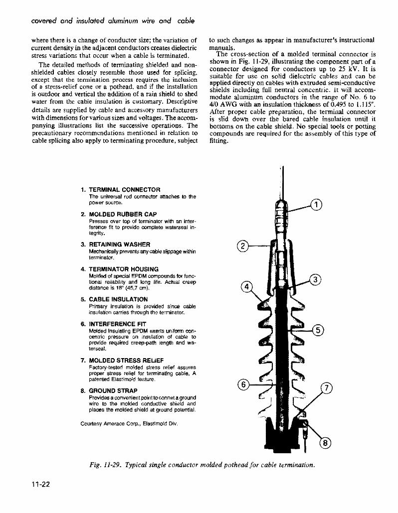
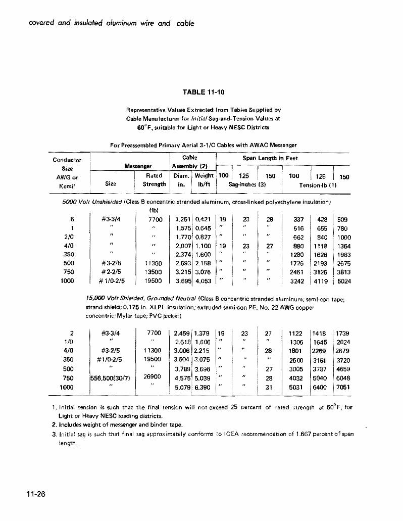
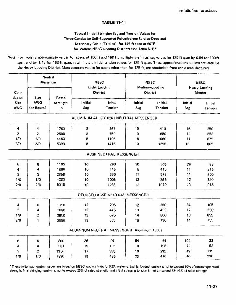