
Installation Operation Maintenance Instructions Model...
16
The Utile Engineering Co. Ltd. 15/07/03 Irthlingborough, Northamptonshire. England Tel: +44 (0) 1933 650216 Fax: +44 (0) 1933 652738 1 IC095 Installation Operation Maintenance Instructions Model HD72 – HD124 Watercooled Gas Compressor Serial Number Site Location Installation Date
Transcript of Installation Operation Maintenance Instructions Model...

The Utile Engineering Co. Ltd. 15/07/03Irthlingborough, Northamptonshire. EnglandTel: +44 (0) 1933 650216Fax: +44 (0) 1933 652738 1 IC095
InstallationOperation
Maintenance Instructions
Model HD72 – HD124Watercooled
Gas Compressor
Serial Number
Site Location
Installation Date
The Utile Engineering Co. Ltd. 15/07/03Irthlingborough, Northamptonshire. EnglandTel: +44 (0) 1933 650216Fax: +44 (0) 1933 652738 2 IC095
Page
General …………………………………………………………………………………….. 3Operating Principle …………………………………………………………………………… 3
Health and Safety …………………………………………………………………………… 4
Technical Specification …………………………………………………………………………… 5Packaging …………………………………………………………………………………….. 5Storage …………………………………………………………………………………….. 5
Handling …………………………………………………………………………………….. 6Installation …………………………………………………………………………………….. 6
Pre Start-up Checks …………………………………………………………………………… 8Start-up …………………………………………………………………………………….. 8Protective Devices …………………………………………………………………………… 8
Operating Notes …………………………………………………………………………… 9Stopping Procedure …………………………………………………………………………… 9Lubrication …………………………………………………………………………………….. 9
Maintenance …………………………………………………………………………………….. 10
Troubleshooting …………………………………………………………………………… 11Check Blade Wear …………………………………………………………………………… 11
Blade Inspection …………………………………………………………………………… 12Reassembly after Blade Inspection ………………………………………………………… 12Cylinder Renewal …………………………………………………………………………… 12
Change Bearings and Seals …………………………………………………………………. 13Reassembly …………………………………………………………………………………….. 13
Spare Parts …………………………………………………………………………………….. 14
Spare Parts List …………………………………………………………………………… 15After Sales Service …………………………………………………………………………… 15
Warranty …………………………………………………………………………………….. 16
WarningRead the installation and maintenance information before commencing work on this equipment. Your attention isdrawn to the health and safety information on page 4. Until the equipment into which the machine has beenincorporated and the said equipment declared to be in conformity with the Machinery Directive, they must not beput into service.
ForewordThe HD series rotary gas compressor has been developed based on many years of experience in the compressorand vacuum pump industry. Using modern design techniques and production methods coupled with rigoroustesting and high quality standards ensure this series of machines have a long, efficient and reliable service life.
These operating instructions have been written for all personnel who have responsibility to the machine, it containsall the necessary information required for the machine to have a long trouble free service life. This manual must bestored near the machine and read before attempting any work on it.
Ensure that all operation and maintenance is only performed by competent and trained personnel and any repairsuse only original parts from the manufacturer.
ContentsContentsForewordContentsForeword
The Utile Engineering Co. Ltd. 15/07/03Irthlingborough, Northamptonshire. EnglandTel: +44 (0) 1933 650216Fax: +44 (0) 1933 652738 3 IC095
GeneralThe normal routine of running the machine is very simple. If it is carried out strictly at all times, many years oftrouble free service can be expected.
We emphasise three points of paramount importance-
1. Filtration of incoming air of gas 2. Lubrication 3. Cooling Water Supply
If possible provide a logbook so that the operator can enter daily readings. After several months a record will showwhether the machine is performing as it did originally. If readings are to be taken the following are all that isrequired. Inlet and outlet air temperatures, suction conditions and oil drip rate.
A typical layout for the log book is shown in the table below.
Machine Log BookDate Inlet Gas
Temp.DischargeGas Temp.
Inlet WaterTemp.
DischargeWaterTemp.
Inlet GasPressure
DischargeGas
Pressure
Oil DripRate.
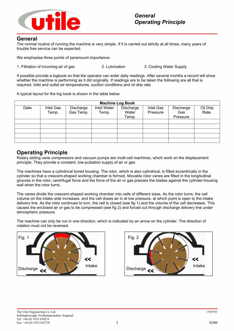
Operating PrincipleRotary sliding vane compressors and vacuum pumps are multi-cell machines, which work on the displacementprinciple. They provide a constant, low-pulsation supply of air or gas.
The machines have a cylindrical bored housing. The rotor, which is also cylindrical, is fitted eccentrically in thecylinder so that a crescent-shaped working chamber is formed. Movable rotor vanes are fitted in the longitudinalgrooves in the rotor; centrifugal force and the force of the air or gas presses the blades against the cylinder-housingwall when the rotor turns.
The vanes divide the crescent-shaped working chamber into cells of different sizes. As the rotor turns, the cellvolume on the intake side increases, and the cell draws air in at low pressure, at which point is open to the intakedelivery line. As the rotor continues to turn, the cell is closed (see fig 1) and the volume of the cell decreases. Thiscauses the enclosed air or gas to be compressed (see fig 2) and forced out through discharge delivery line underatmospheric pressure.
The machine can only be run in one direction, which is indicated by an arrow on the cylinder. The direction ofrotation must not be reversed.
Fig. 1
Discharge Intake
Fig. 2
Discharge Intake
GeneralOperating Principle
The Utile Engineering Co. Ltd. 15/07/03Irthlingborough, Northamptonshire. EnglandTel: +44 (0) 1933 650216Fax: +44 (0) 1933 652738 4 IC095
Read the installation and operating instructions carefully.Rotating machinery and pressurised components, which may contain toxic, flammable or otherwise hazardousmedia are potentially dangerous equipment if not operated and maintained correctly. It is imperative that all usersof such equipment fully educate themselves to the potential dangers and satisfy themselves that the personnelresponsible for installing, testing, commissioning, operating and maintaining the plant are competent to do so.Instruction manuals are provided for guidance but must assume some basic level of competence by users. If thereare any doubts or ambiguities concerning correct procedures, ask Utile Engineering. DO NOT TAKE RISKS.
Certain machinery can generate high levels of noise which can be harmful if exposed to it for lengthy periods oftime. Various codes of practice are in existence and users must ensure that adequate precautions are taken toprevent a health hazard to employees or third party.
Equipment with internal pressures above or below ambient pressures can create a hazard. Before attempting toinvestigate problems, service or maintain equipment, it must be safely depressurised or pressurised to ambientconditions. Also since the gaseous medium may be flammable, toxic, corrosive or otherwise hazardous it may benecessary to purge the installation with an inert gas, such as nitrogen. Special precautions are necessary forcertain gases and the user must ensure that adequate procedures are implemented.
Moving parts of machinery must not be touched and all such parts must be adequately guarded. Suitable guardsare provided and must be securely retained in position at all times.
Before commencing maintenance, servicing or making other adjustments, the prime mover and other equipmentmust be isolated electrically or otherwise immobilised to prevent accidental start-up. In this vein, a fully qualifiedelectrician should carry out all electrical work and all electrical equipment should be isolated before it is touchedand pneumatic or hydraulic controls depressurised and made safe. Procedures must also exist to ensure thatelectrical or other inputs cannot be restored accidentally during the maintenance or service period.Safety trips, emergency stop-buttons and other such devices (if fitted) are to be checked regularly to ensure thatthey continue to function correctly and will protect the installation and personnel in the event of an emergency.
NO attempt should be made to touch the machine whilst it is rotating. Particular care is needed when checkingrotor clearances. Any movement of rotors may trap fingers.
Most machines, certain pipes and ancillaries become hot during operation whilst certain machines with sub-zeroinlet temperatures may result in very cold surfaces. If it is possible for personnel to come into contact with suchsurfaces unknowingly or accidentally they should be guarded.
If severe vibration is observed, the cause of this should be immediately investigated and the situation rectified.Excessive vibration can lead to fatigue and other failures. Similarly, if during operation a significant change isnoticed in the level of vibration, noise, temperature or any other parameter, the cause of such changes must bedetermined, and the cause rectified. Inlet filters must be inspected regularly so that liquid or debris is not allowed toenter the machine, which could cause damage and consequently injury to personnel.
During routine maintenance, coupling alignment should be checked for misalignment.Only approved lubricants must be used and quantities, etc must be checked regularly.
Before restarting after servicing, all nuts, set screws, etc must be checked for tightness, check all joints, for leaksand carry out purging as necessary before introducing the process gas. Also, before start-up, check the machineinlet and outlet isolating valves are open both non-return valves (if fitted) are the correct orientation.
Adjacent pipework and equipment must not impose undue forces and moments on the machinery flanges.All welding work must be carried out be an approved gas coded welder.In order to prevent reverse rotation of machines, it is ESSENTIAL that a non-return valve be installed in the inletpipework. Otherwise a hazardous situation can arise during a normal shutdown or if the prime mover power supplyis interrupted for a period of time.
The environment around the installation may need to be monitored in order to detect gas leaks etc., andconsideration must be given to the installation of gas detecting equipment, and the class of electric equipment.All personnel working in or passing through the area should be adequately warned by signs and trained to exerciseappropriate safety precautions. Ensure the correct personal protective equipment is worn at all times.
Health and Safety
The Utile Engineering Co. Ltd. 15/07/03Irthlingborough, Northamptonshire. EnglandTel: +44 (0) 1933 650216Fax: +44 (0) 1933 652738 5 IC095
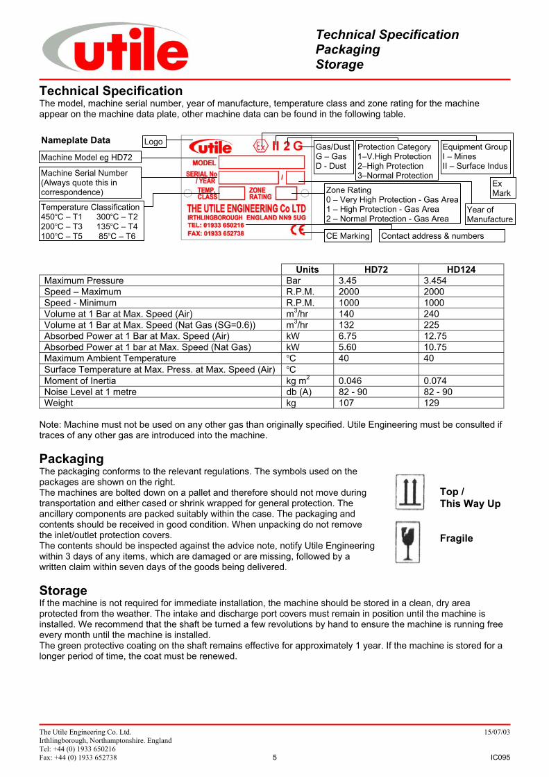
Technical SpecificationThe model, machine serial number, year of manufacture, temperature class and zone rating for the machineappear on the machine data plate, other machine data can be found in the following table.
Units HD72 HD124Maximum Pressure Bar 3.45 3.454Speed – Maximum R.P.M. 2000 2000Speed - Minimum R.P.M. 1000 1000Volume at 1 Bar at Max. Speed (Air) m3/hr 140 240Volume at 1 Bar at Max. Speed (Nat Gas (SG=0.6)) m3/hr 132 225Absorbed Power at 1 Bar at Max. Speed (Air) kW 6.75 12.75Absorbed Power at 1 bar at Max. Speed (Nat Gas) kW 5.60 10.75Maximum Ambient Temperature °C 40 40Surface Temperature at Max. Press. at Max. Speed (Air) °CMoment of Inertia kg m2 0.046 0.074Noise Level at 1 metre db (A) 82 - 90 82 - 90Weight kg 107 129
Note: Machine must not be used on any other gas than originally specified. Utile Engineering must be consulted iftraces of any other gas are introduced into the machine.
PackagingThe packaging conforms to the relevant regulations. The symbols used on thepackages are shown on the right.The machines are bolted down on a pallet and therefore should not move duringtransportation and either cased or shrink wrapped for general protection. Theancillary components are packed suitably within the case. The packaging andcontents should be received in good condition. When unpacking do not removethe inlet/outlet protection covers.The contents should be inspected against the advice note, notify Utile Engineeringwithin 3 days of any items, which are damaged or are missing, followed by awritten claim within seven days of the goods being delivered.
StorageIf the machine is not required for immediate installation, the machine should be stored in a clean, dry areaprotected from the weather. The intake and discharge port covers must remain in position until the machine isinstalled. We recommend that the shaft be turned a few revolutions by hand to ensure the machine is running freeevery month until the machine is installed.The green protective coating on the shaft remains effective for approximately 1 year. If the machine is stored for alonger period of time, the coat must be renewed.
Technical SpecificationPackagingStorage
Top /This Way Up
Fragile
Nameplate Data
Machine Model eg HD72
Machine Serial Number(Always quote this incorrespondence)
Logo
Temperature Classification450°C – T1 300°C – T2200°C – T3 135°C – T4100°C – T5 85°C – T6 CE Marking Contact address & numbers
Zone Rating0 – Very High Protection - Gas Area1 – High Protection - Gas Area2 – Normal Protection - Gas Area
Year ofManufacture
ExMark
Equipment GroupI – MinesII – Surface Indus
Gas/DustG – GasD - Dust
Protection Category1–V.High Protection2–High Protection3–Normal Protection
The Utile Engineering Co. Ltd. 15/07/03Irthlingborough, Northamptonshire. EnglandTel: +44 (0) 1933 650216Fax: +44 (0) 1933 652738 6 IC095
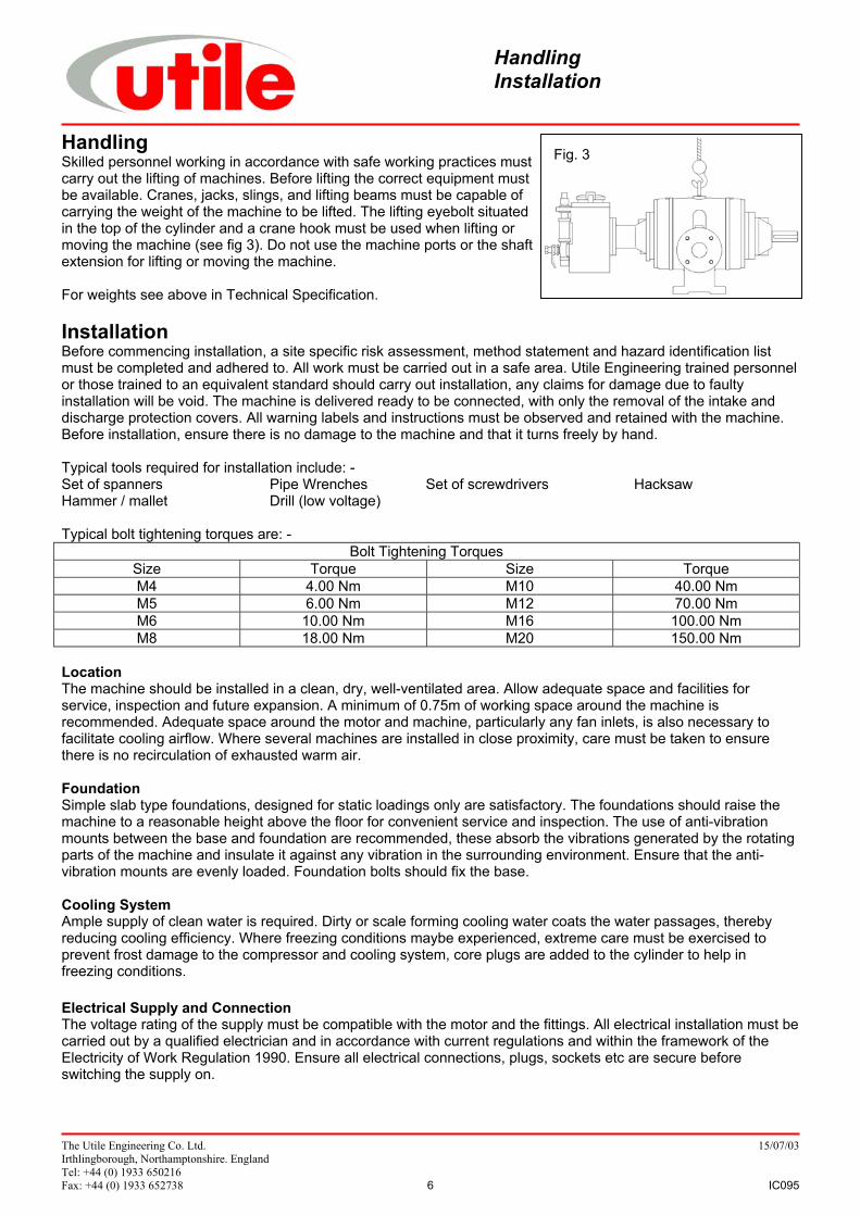
Fig. 3HandlingSkilled personnel working in accordance with safe working practices mustcarry out the lifting of machines. Before lifting the correct equipment mustbe available. Cranes, jacks, slings, and lifting beams must be capable ofcarrying the weight of the machine to be lifted. The lifting eyebolt situatedin the top of the cylinder and a crane hook must be used when lifting ormoving the machine (see fig 3). Do not use the machine ports or the shaftextension for lifting or moving the machine.
For weights see above in Technical Specification.
InstallationBefore commencing installation, a site specific risk assessment, method statement and hazard identification listmust be completed and adhered to. All work must be carried out in a safe area. Utile Engineering trained personnelor those trained to an equivalent standard should carry out installation, any claims for damage due to faultyinstallation will be void. The machine is delivered ready to be connected, with only the removal of the intake anddischarge protection covers. All warning labels and instructions must be observed and retained with the machine.Before installation, ensure there is no damage to the machine and that it turns freely by hand.
Typical tools required for installation include: -Set of spanners Pipe Wrenches Set of screwdrivers HacksawHammer / mallet Drill (low voltage)
Typical bolt tightening torques are: -Bolt Tightening Torques
Size Torque Size TorqueM4 4.00 Nm M10 40.00 NmM5 6.00 Nm M12 70.00 NmM6 10.00 Nm M16 100.00 NmM8 18.00 Nm M20 150.00 Nm
LocationThe machine should be installed in a clean, dry, well-ventilated area. Allow adequate space and facilities forservice, inspection and future expansion. A minimum of 0.75m of working space around the machine isrecommended. Adequate space around the motor and machine, particularly any fan inlets, is also necessary tofacilitate cooling airflow. Where several machines are installed in close proximity, care must be taken to ensurethere is no recirculation of exhausted warm air.
FoundationSimple slab type foundations, designed for static loadings only are satisfactory. The foundations should raise themachine to a reasonable height above the floor for convenient service and inspection. The use of anti-vibrationmounts between the base and foundation are recommended, these absorb the vibrations generated by the rotatingparts of the machine and insulate it against any vibration in the surrounding environment. Ensure that the anti-vibration mounts are evenly loaded. Foundation bolts should fix the base.
Cooling SystemAmple supply of clean water is required. Dirty or scale forming cooling water coats the water passages, therebyreducing cooling efficiency. Where freezing conditions maybe experienced, extreme care must be exercised toprevent frost damage to the compressor and cooling system, core plugs are added to the cylinder to help infreezing conditions.
Electrical Supply and ConnectionThe voltage rating of the supply must be compatible with the motor and the fittings. All electrical installation must becarried out by a qualified electrician and in accordance with current regulations and within the framework of theElectricity of Work Regulation 1990. Ensure all electrical connections, plugs, sockets etc are secure beforeswitching the supply on.
HandlingInstallation
The Utile Engineering Co. Ltd. 15/07/03Irthlingborough, Northamptonshire. EnglandTel: +44 (0) 1933 650216Fax: +44 (0) 1933 652738 7 IC095
EarthingIt is important that the motor enclosure is soundly earthed by metallic earth continuity conductor, or by separateearth bonding, but in all cases the installation must be made and tested and approved for this feature by a qualifiedinstaller before the supply is applied to the motor.
Fitting Pulleys and CouplingsThese should be bored to our standard limits (details supplied upon request) and fitted to the shaft with a screwingmotion. On no account should they be driven on. Tapping of fitments onto the machine shaft with a hammer ormallet, causes bearing damage. This results in an increase in bearing noise and a significant reduction in bearinglife. Attention should be paid to the guarding of all moving parts.
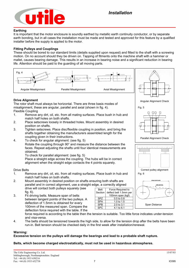
Drive AlignmentThe rotor shaft must always be horizontal. There are three basis modes ofmisalignment, these are angular, parallel and axial (shown in fig. 4).Flexible Coupling1. Remove any dirt, oil, etc. from all mating surfaces. Place bush in hub and
match half holes on both shafts.2. Place setscrews loosely in threaded holes. Mount assembly in desired
position on shafts.3. Tighten setscrews. Place disc/flexible coupling in position, and bring the
shafts together obtaining the manufacturers assembled length for thecoupling given in their instructions.
4. To check for angular alignment: (see fig. 5)Rotate the coupling through 90° and measure the distance between the faces. Repeat adjusting the shafts until four identical measurements are obtained.To check for parallel alignment: (see fig. 5)Place a straight edge across the coupling. The hubs will be in correct alignment when the straight edge contacts the 4 points squarely.
Drive Belts1. Remove any dirt, oil, etc. from all mating surfaces. Place bush in hub and
match half holes on both shafts.2. Mount assembly in desired position on shafts ensuring both shafts are
parallel and in correct alignment, use a straight edge, a correctly aligneddrive will contact both pulleys squarely (seefig. 6).
3. Fit driving belts. Measure span of beltsbetween tangent points of the two pulleys. Adeflection of 1.5mm is obtained for every100mm of the measured span. Compare thedeflection force required with the table. If theforce required is according to the table then the tension is suitable. Too little force indicates under-tensionand visa-versa.
4. The belts should be tensioned towards the high side, to allow for the tension drop after the belts have beenrun-in. Belt tension should be checked daily in the first week after installation/renewal.
Warning:Excessive tension on the pulleys will damage the bearings and lead to a probable shaft rupture.
Belts, which become charged electrostatically, must not be used in hazardous atmospheres.
BeltSection
Force Required todeflect belt 1.5mm per
100mm span (kgf)SPZ 0.5 to 0.8SPA 1.0 to 1.5SPB 2.0 to 3.1SPC 4.1 to 6.1
Parallel Alignment Check
Angular Alignment Check
Fig. 5
Angular Misalignment Parallel Misalignment Axial Misalignment
Fig. 4
Correct pulley alignment
Span Distance
Fig. 6
Installation
The Utile Engineering Co. Ltd. 15/07/03Irthlingborough, Northamptonshire. EnglandTel: +44 (0) 1933 650216Fax: +44 (0) 1933 652738 8 IC095
Pipework The connecting pipework must be completely clean, dry and free from internal rust or scale. When fitting the intake and discharge pipework it is essential that adequate supports be provided and that it is
properly aligned to prevent excessive strain being placed upon the machine, flexible pipe should be placed inthe pipeline to remove this strain.
During installation care must be taken to ensure that no foreign matter enters the machine or serious damagemay result.
An intake filter should be fitted into the intake side to prevent any particles from entering the machine. Use P.T.F.E. tape only as a jointing medium since surplus from jointing compounds will damage the blades if
drawn into the machine. When the machine is delivering into or exhausting from a receiver, or working with a system having a large
storage capacity, it is essential to fit a non-return valve in the pipework, preferably on the discharge side toprevent the machine from running in reverse on shutdown.
Arrange both the intake and discharge pipework so that any condensate flows away from the machine. If user is installing their own protective switches and other devices these must be suitable for operation in the
zone classified. All pipework and fittings must comply with IGE/UP/2 or the national standard for the country of installation.
Pre Start-up ChecksBefore starting the machine for the first time after installation, maintenance or after a long downtime, make thefollowing checks: -
Ensure all the anchor bolts for the machine, base and motor are securely fastened. Check that the machine is free running by turning the shaft by hand through a few revolutions. Flick start the motor to check that the direction of rotation agrees with the arrow on top of the machine cylinder.
Note this should be completed with the coupling/drive belts removed. Recheck coupling/drive alignment and retension (see page 7). Ensure all equipment is installed and earthed in accordance with current legislation. Check all piping connections. If the system is to be pressure tested, all gauges and pressure switches must be
isolated or removed. Maximum purge or pressure test is 1.50 times the working pressure. Check all protective devices ensuring they are working correctly. Ensure personnel are adequately protected from accidental contact with all dangerous equipment. Fill the oil reservoir with Shell Corena P150 oil or equivalent, prime the oil lines to the machine. Instruct the operating personnel that the machine is operational.
Protective DevicesAll pressure and temperature switches must be set and tested at the desired set point by simulating the set point inactual operation.With the machine running at the duty pressure after warming up, adjust the discharge temperature switchdownwards to actuate and stop the machine. Reset the switch at the cut out temperature plus 10°C - 15°C in orderto avoid false tripping from small and reasonable increases above normal levels.
Adjust the high pressure cut out switch in the same manner and reset at working pressure plus 10%.
After the first 50 running hours, remove the cone shaped mesh strainer from the inlet, clean and replace.If a large amount of debris has been collected run for a further 50 hour period repeating the process until the filterremains clean.
Start-upProceed as follows: -
i. When starting compressors the intake valves are fully open. Compressors can usually be started againstnormal discharge pressure. Open cooling water supply and throttle to a moderate flow rate.
ii. Some compressors are piped with a manual start-up bypass valve from discharge to intake, for pressureequalisation during startup, This must be fully opened before startup.
iii. Start the drive motor and bring the machine up to operating speed. iv. When full speed is reached slowly close the manual start-up bypass valve. Regulate the water flow until the
outlet water from the cylinder is 27°C – 38°C at operating pressure. v. Check and adjust the lubricator drip rate to that indicated in the lubrication section. vi. Check all protective devices and controls making sure they are working correctly.
Pre Start-up ChecksProtective DevicesStart-up
The Utile Engineering Co. Ltd. 15/07/03Irthlingborough, Northamptonshire. EnglandTel: +44 (0) 1933 650216Fax: +44 (0) 1933 652738 9 IC095
Fig. 7
Operating Notes Daily, check the oil drip rate through the indicator. Fill the oil reservoir. After the initial running in period, check belt tension. Belt squeal denotes a loose belt that requires tightening. Inspect the filter fitted to the inlet, regularly clean and renew the element when necessary.
Excessive discharge temperature for normal operation, indicated by the rise in temperature shown in the logbook indicates inadequate cooling, faulty lubrication or a dirty intake filter. Stop and inspect the machine.
Check the machine internally for wear every 10,000 running hours. (see Inspection and Service) The blade depth should be checked after the initial 2,000 running hours and thereafter every 5,000 running
hours for wear and renew if the rubbing tips have worn to a depth of 33mm. (see Check Blade Wear).Condensate if allowed to enter the machine can cause severe blade wear.
If adjustment of the oil drip rate is required (see lubrication). If machine is on a standby service, run for a few minutes each week.
Stopping ProcedureProceed as follows: -
i. Trip out or Stop the drive motor. ii. Stop the cooling water immediately. If freezing
conditions are likely to be encountered thendrain off the compressor unless closed circuitcooling with anti-freeze is being used.
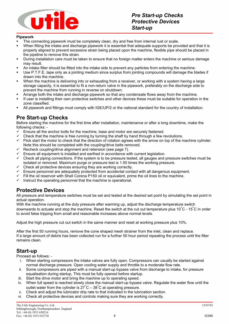
LubricationThe recommended grade of oil is Shell Corena P150the typical physical characteristics right.
Prime oil pipes prior to initial start and every timemachine is dismantled for service, as serious damagewill occur if the machine runs unlubricated.
Oil feed rate per indicator is shown below. These can beincreased/decreased pro-rata with speed.
Lubricator MaintenanceAfter filling the container with oil through the strainer (1)uncouple the union nut (2) and remove guide wire (4).Fill the sight glass (5) and glassholder (7) with water(preferably clean and condensed). A 50 % glycerinesolution will prevent freezing to -5°C with most oils it willimprove the passage of the oil globules through the sightfeed tube. Screw in the regulator sleeve (21) and locknut(22) to furthest 'in' position so allowing maximum plungerstroke. Open the air vent screw (12) two full turns and operate pump by the trigger (19) until oil flows freely from theair vent. Tighten vent screw, replace the guide wire and the union nut. Loosen the connector at end of feed pipeand continue pumping by hand until oil flows freely, indicating that the pipe is filled. Tighten the connector andrepeat sequence for each feed. When the machine starts the lubricator will function with all feeds on maximumoutput. Adjusting the position of the sleeves and locknuts (21 & 22) can regulate this. Should the lubricator beallowed to empty it may be necessary to expel air by releasing the air vent screw and operating trigger as above.To clean/renew a sight glass, uncouple the union nut and remove the guide wire. The non-return valve (3) willprevent loss of oil from the feed pipe. Loosen the top lockring (8) with spanner (E8) and run the lower ring to thebottom of the glassholder shank. Lift the holder and remove the glass. Each pump unit leaves the factory with theplunger gland packing adjusted. To tighten the packing gland nut (17) screw in the regulator sleeve and locknutusing spanner (E8) taking care not to overtighten. The pump unit delivery valves (24) with spring (25) can beinspected by unscrewing the nozzle (23) after first removing the sight glass. To inspect the suction valves (26)remove valve cap (28) and unscrew the valve housing (27). This should be screwed in tightly when re-assembling.
Operating NotesStopping ProcedureLubrication
Shell Corena Oil P150Kinematic Viscosity@ 40°C cSt 100°C cSt (IP71)
15010.9
ISO Viscosity Grade (IP226) 150Pour Point °C (IP15) -21Density @ 15°C kg/l (IP365) 0.886Flash Point (PMCC) °C (IP34) 213Water Separability (ASTM-D1401) 10Foaming Characteristics (IP146/ASTM-D892) Nil/Nil
Speed 1000 Rpm Speed 1400 RpmModel Air/Nat Biogas Air/Nat BiogasHD72 0.75 0.90 1.00 1.25HD124 0.75 0.90 1.00 1.25
The Utile Engineering Co. Ltd. 15/07/03Irthlingborough, Northamptonshire. EnglandTel: +44 (0) 1933 650216Fax: +44 (0) 1933 652738 10 IC095
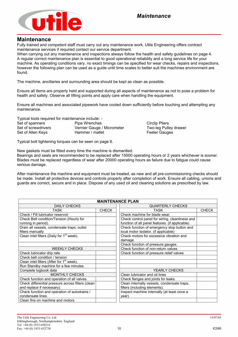
MaintenanceFully trained and competent staff must carry out any maintenance work. Utile Engineering offers contractmaintenance services if required contact our service department.When carrying out any maintenance and inspections always follow the health and safety guidelines on page 4.A regular correct maintenance plan is essential to good operational reliability and a long service life for yourmachine. As operating conditions vary, no exact timings can be specified for wear checks, repairs and inspections,however the following plan can be used as a guide until time scales to better suit the machines environment arefound.
The machine, ancillaries and surrounding area should be kept as clean as possible.
Ensure all items are properly held and supported during all aspects of maintenance as not to pose a problem forhealth and safety. Observe all lifting points and apply care when handling the equipment.
Ensure all machines and associated pipework have cooled down sufficiently before touching and attempting anymaintenance.
Typical tools required for maintenance include: -Set of spanners Pipe Wrenches Circlip PliersSet of screwdrivers Vernier Gauge / Micrometer Two-leg Pulley drawerSet of Allen Keys Hammer / mallet Feeler Gauges
Typical bolt tightening torques can be seen on page 6.
New gaskets must be fitted every time the machine is dismantled.Bearings and seals are recommended to be replaced after 15000 operating hours or 2 years whichever is sooner.Blades must be replaced regardless of wear after 20000 operating hours as failure due to fatigue could causeserious damage.
After maintenance the machine and equipment must be treated, as new and all pre-commissioning checks shouldbe made. Install all protective devices and controls properly after completion of work. Ensure all cabling, unions andguards are correct, secure and in place. Dispose of any used oil and cleaning solutions as prescribed by law.
MAINTENANCE PLANDAILY CHECKS QUARTERLY CHECKS
TASK CHECK TASK CHECKCheck / Fill lubricator reservoir Check machine for blade wear.Check Belt condition/Tension (Hourly forrunning in period).
Check control panel for wiring, cleanliness andfunction of all panel features. (if applicable)
Drain all vessels, condensate traps, outletfilters manually
Check function of emergency stop button andlocal motor isolator. (if applicable)
Clean inlet filters (Daily for 1st week). Check motors for excessive vibration anddamage.Check function of pressure gauges.
WEEKLY CHECKS Check function of non-return valvesCheck lubricator drip rate Check function of pressure relief valvesCheck belt condition / tensionClean inlet filters (After for 1st week).Run Standby machine for a few minutes.Complete logbook data YEARLY CHECKS
MONTHLY CHECKS Clean lubricator and oil linesCheck function and operation of all valves. Check flanges and joints for leaks.Check differential pressure across filters (cleanand replace if necessary).
Clean internally vessels, condensate traps,filters (including elements).
Check function and operation of autodrains /condensate lines.
Inspect machine internally (at least once ayear)
Clean fins on machine and motors
Maintenance
The Utile Engineering Co. Ltd. 15/07/03Irthlingborough, Northamptonshire. EnglandTel: +44 (0) 1933 650216Fax: +44 (0) 1933 652738 11 IC095
Fig. 8
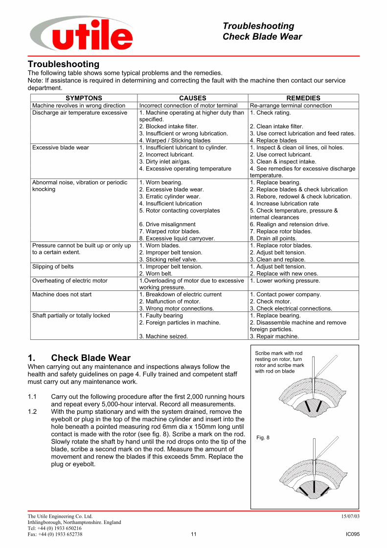
Scribe mark with rodresting on rotor, turnrotor and scribe markwith rod on blade
TroubleshootingThe following table shows some typical problems and the remedies.Note: If assistance is required in determining and correcting the fault with the machine then contact our servicedepartment.
1. Check Blade WearWhen carrying out any maintenance and inspections always follow thehealth and safety guidelines on page 4. Fully trained and competent staffmust carry out any maintenance work.
1.1 Carry out the following procedure after the first 2,000 running hoursand repeat every 5,000-hour interval. Record all measurements.
1.2 With the pump stationary and with the system drained, remove theeyebolt or plug in the top of the machine cylinder and insert into thehole beneath a pointed measuring rod 6mm dia x 150mm long untilcontact is made with the rotor (see fig. 8). Scribe a mark on the rod.Slowly rotate the shaft by hand until the rod drops onto the tip of theblade, scribe a second mark on the rod. Measure the amount ofmovement and renew the blades if this exceeds 5mm. Replace theplug or eyebolt.
SYMPTONS CAUSES REMEDIESMachine revolves in wrong direction Incorrect connection of motor terminal Re-arrange terminal connection
1. Machine operating at higher duty thanspecified.
1. Check rating.
2. Blocked intake filter. 2. Clean intake filter.3. Insufficient or wrong lubrication. 3. Use correct lubrication and feed rates.
Discharge air temperature excessive
4. Warped / Sticking blades 4. Replace blades1. Insufficient lubricant to cylinder. 1. Inspect & clean oil lines, oil holes.2. Incorrect lubricant. 2. Use correct lubricant.3. Dirty inlet air/gas. 3. Clean & inspect intake.
Excessive blade wear
4. Excessive operating temperature 4. See remedies for excessive dischargetemperature.
1. Worn bearing. 1. Replace bearing.2. Excessive blade wear. 2. Replace blades & check lubrication3. Erratic cylinder wear. 3. Rebore, redowel & check lubrication.4. Insufficient lubrication 4. Increase lubrication rate5. Rotor contacting coverplates 5. Check temperature, pressure &
internal clearances6. Drive misalignment 6. Realign and retension drive.7. Warped rotor blades. 7. Replace rotor blades.
Abnormal noise, vibration or periodicknocking
8. Excessive liquid carryover. 8. Drain all points.1. Worn blades. 1. Replace rotor blades.2. Improper belt tension. 2. Adjust belt tension.
Pressure cannot be built up or only upto a certain extent.
3. Sticking relief valve. 3. Clean and replace.1. Improper belt tension. 1. Adjust belt tension.Slipping of belts2. Worn belt. 2. Replace with new ones.
Overheating of electric motor 1.Overloading of motor due to excessiveworking pressure.
1. Lower working pressure.
1. Breakdown of electric current 1. Contact power company.2. Malfunction of motor. 2. Check motor.
Machine does not start
3. Wrong motor connections. 3. Check electrical connections.1. Faulty bearing 1. Replace bearing.2. Foreign particles in machine. 2. Disassemble machine and remove
foreign particles.
Shaft partially or totally locked
3. Machine seized. 3. Repair machine.
TroubleshootingCheck Blade Wear
The Utile Engineering Co. Ltd. 15/07/03Irthlingborough, Northamptonshire. EnglandTel: +44 (0) 1933 650216Fax: +44 (0) 1933 652738 12 IC095
2. Blade InspectionWhen carrying out any maintenance and inspections always follow the health and safety guidelines on page 4.Ensure all electric circuits are isolated and cannot be switched on, and that the pipeline system has been clearedand is pressurised to atmospheric pressure. Fully trained and competent service personnel must carry out anymaintenance work.
Inspection commences with the dismantling of the rear end, after removal of the oil tank and pipes.
2.1 Undo four nuts (33) and remove lubricator (25) taking care not to lose the coupling spider (24).2.2 Undo four screws (18) and remove end cap (5) complete with mechanical oil seal seat. Remove 'O' ring
(14) from the groove in coverplate. Inspect the faces of the mechanical seal for wear and replace completeseal if either are worn. Shims may be fitted between the end cap and the outer race of the roller bearing (9)and care must be taken not to lose or damage these items. Remove the mechanical seal (11) taking carenot to damage the carbon face. If the seal sticks on the shaft, carefully prise free with a screwdriverbetween the spring locating ring and the locknut (12).
2.3 Remove the locknut (12) and tab washer (13).2.4 Take off eight nuts (16) and washers (17) and remove coverplate (3) complete with outer race of roller
bearing (9) and oil seal (21) by using 1/2"UNC x 2 1/2" long jacking screws in the dowel positions (20).2.5 Measure and note the thickness of the gasket (22) fitted between the coverplate (3) and cylinder (1).2.6 The blades (7) can now be removed form their slots for inspection.
Check the blades for lamination, chipping or charring on their rubbing edges and for concave wear. For anyother wear other than polished surfaces or if blade depth has is 33mm or below then replace the blades.When replacing blades a complete set must be replaced. The old blades must be disposed of according tothe local government laws. When fitting new blades, ensure they slide freely in their slots and if necessaryremove high spots with fine emery cloth. Lightly smear blade surfaces with oil before reassembly.
2.7 Inspect the visible part of the cylinder bore and rotor for any signs of excessive wear or scuffing and forexcessive slot wear. If there is any sign of cylinder rubbing completely dismantle the machine. Factoryreconditioning is recommended, but if work has to be carried out on site, we advise you most strongly tocontact Utile Engineering Service Department for advice.During inspection, determine if the correct oil is being used. Bearings, cylinder wall, rotor/shaft assemblyand blades should show a polished surface with a light film of oil. Hard baked deposits indicate inferior oil,dirt or excessive temperature.
3. Reassembly after Blade InspectionReassemble in the reverse order, taking note of the following points: -
3.1 Ensure the blades are orientated correctly in their slots.3.2 If coverplate gaskets have been replaced it is essential they are the same thickness as the originals, as
clearances will be affected and could cause serious damage. Lightly smear with oil before replacing.3.3 Replace coverplate over cylinder studs. Tighten retaining nuts to a torque of 110Nm.3.4 Secure bearing locknut and tab washer and replace remaining parts. Soapy water should be used to re-
assemble the mechanical seal onto the shaft.3.5 When assembled make sure the compressor turns freely by hand.3.6 Before fitting oil pipes, prime with correct grade of oil as described in the LUBRICATION section.
4. Cylinder RenewalWith the rear end coverplate (3) already removed as described in 2 for blade inspection, the next stage is toremove the drive end coverplate (2) and rotor/shaft assembly.
4.1 Undo four screws (19) and remove end cap (3) complete with mechanical oil seal seat. Remove 'O' ring(14) from groove in coverplate. Shims may be fitted between the end cap and outer race of bearing (10)and care must be taken not to lose these. Inspect both faces of the mechanical seal for wear and replacecomplete seal if either are worn. Remove the mechanical seal (11) taking care not to damage the carbonface. If the seal sticks on the shaft, and carefully prise free with a screwdriver between the spring locatingring and locknut (12).
4.2 Undo and remove the locknut (12) and tab washer (13).
Blade Inspection,Reassembly after Blade Inspection,Cylinder Renewal,
The Utile Engineering Co. Ltd. 15/07/03Irthlingborough, Northamptonshire. EnglandTel: +44 (0) 1933 650216Fax: +44 (0) 1933 652738 13 IC095
Fig 9
Fig 10
4.3 Take off eight nuts (16) and washers (17) and remove coverplate (3) complete with ball bearing (10), outerrace of roller bearing (9) and oil seal (21) by using 1/2"UNC x 2 1/2" long jacking screws in the dowelpositions (20). Measure and note the thickness of the gasket (22) fitted between the coverplate (2) andcylinder (1). Remove rotor assembly. The cylinder can now be replaced or rebored.
4.4 When reboring the cylinder the maximum allowable increase in diameter is 0.8mm to give a final bore of153.30mm. Contact Utile Engineering for appropriate assembly instructions in this case.
5. Removal of Bearings and SealsWith the rear end coverplate (3) already removed as described in 2 for blade inspection.
5.1 Using a two-leg pulley drawer the roller bearing inner race (9) can be removed from the shaft.5.2 Should the seal sleeve (8) show signs of wear, then it can be removed by careful machining. Before
removal, record the width of the sleeve using a depth micrometer measuring from sleeve face to rotor face.5.3 The bearing seal (21) and roller bearing outer race (9) can be pressed out of the coverplate for inspection.5.4 Inspect the bearing, renew if it shows any signs of wear or pitting.5.5 Examine the bearing seal (21) and renew if the wiping lip is worn or damaged.
With the drive end coverplate (2) already removed complete with rotor as described in 4 for cylinder renewal.
5.6 Using a two-leg pulley drawer the roller bearing inner race (9) can be removed from the shaft.5.7 Should the seal sleeve (9) show signs of wear, then it can be removed by careful machining. Before
removal, record the width of the sleeve using a depth micrometer measuring from sleeve face to rotor face.5.8 The bearing seal (21) ball bearing (10) and roller bearing outer race (9) can be pressed out of the
coverplate for inspection renew if they show any signs of wear or pitting.5.9 Examine the bearing seal (21) and renew if the wiping lip is worn or damaged.
6. Reassembly ProcedureThis section only applies when using original bore size or replacement cylinder. Before commencing reassemblyensure all components are perfectly clean and oilways are clear. Lightly smear the shaft with oil to assist assembly.
The correct clearances for these machines are: -HD72 HD124
Drive End Coverplate / Rotor 0.13mm / 0.18mm 0.13mm / 0.18mmRear End Coverplate / Rotor 0.33mm / 0.38mm 0.51mm / 0.55mmRotor / Cylinder 0.13mm / 0.15mm 0.13mm / 0.15mm
The clearances must be reset after:a) Renewal of seal sleeve.b) Refacing of coverplates orc) Facing rotor without removal of seal sleeve.
Reassembly should start with the resetting of clearances if any of theabove three procedures have been completed. If not required go to 6.7.
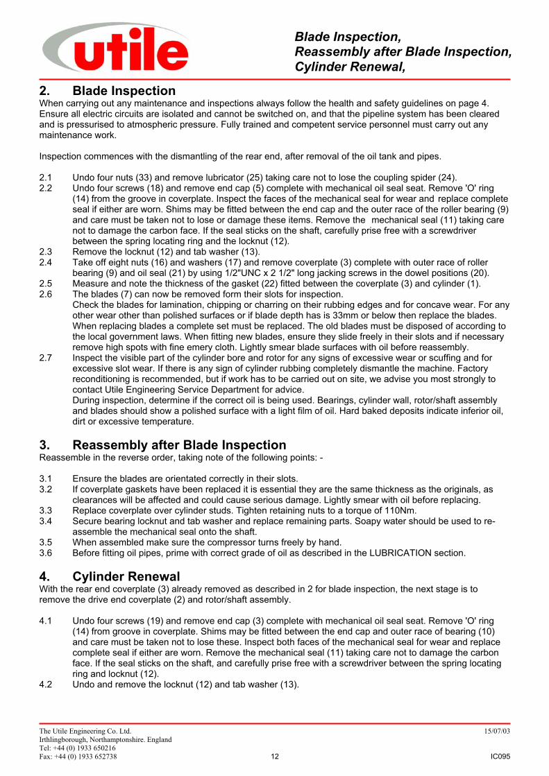
6.1 Make accurate metal "dummy" distance piece to replace the ball and rollerbearings. See Fig 9.
6.2 Slide new seal sleeve onto shaft. Fit "dummy" bearings into coverplate andslide assembly over shaft. Replace bearing locknut and washer and tighten.Replace end cap, shims and mechanical seal. Soapy water should be used tore-assemble the mechanical seal on the shaft.
6.3 Measure clearance between coverplate and rotor using a shim stock as Fig10. This should be within +/- 0.25mm (0.001") of that shown on the machineclearance plate and excess will have to be ground from width of seal sleeve.After grinding repeat above procedure and recheck for correct clearance.
6.4 When correct clearance has been established the seal sleeve can then befixed to the shaft thoroughly degrease components, use Loctite primer and 648 adhesive or equivalent.Press sleeve firmly against the rotor whilst the adhesive is setting.
6.5 Grind the rear end replacement sleeve to length measured in 5.2 and fit to shaft by adhesive (See 6.4).
Change Bearings and Seals,Reassembly Procedure
The Utile Engineering Co. Ltd. 15/07/03Irthlingborough, Northamptonshire. EnglandTel: +44 (0) 1933 650216Fax: +44 (0) 1933 652738 14 IC095
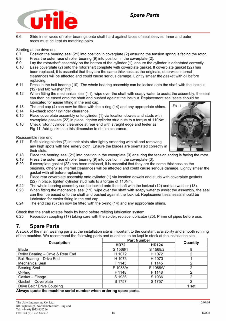
Fig 11
6.6 Slide inner races of roller bearings onto shaft hard against faces of seal sleeves. Inner and outerraces must be kept as matching pairs.
Starting at the drive end6.7 Position the bearing seal (21) into position in coverplate (2) ensuring the tension spring is facing the rotor.6.8 Press the outer race of roller bearing (9) into position in the coverplate (2).6.9 Lay the rotor/shaft assembly on the bottom of the cylinder (1), ensure the cylinder is orientated correctly.6.10 Ease coverplate (2) onto the rotor/shaft complete with coverplate gasket. If coverplate gasket (22) has
been replaced, it is essential that they are the same thickness as the originals, otherwise internal clearances will be affected and could cause serious damage. Lightly smear the gasket with oil before replacing.
6.11 Press in the ball bearing (10). The whole bearing assembly can be locked onto the shaft with the locknut (12) and tab washer (13).
6.12 When fitting the mechanical seal (11), wipe over the shaft with soapy water to assist the assembly, the sealcan then be eased onto the shaft and pushed against the locknut. Replacement seal seats should be lubricated for easier fitting in the end cap.
6.13 The end cap (4) can now be fitted with the o-ring (14) and any appropriate shims.6.14 Re-check rotor / cylinder clearance.6.15 Place coverplate assembly onto cylinder (1) via location dowels and studs with
coverplate gaskets (22) in place, tighten cylinder stud nuts to a torque of 110Nm.6.16 Check rotor / cylinder clearance at rear end with straight edge and feeler as
Fig 11. Add gaskets to this dimension to obtain clearance.
Reassemble rear end6.17 Refit sliding blades (7) in their slots after lightly smearing with oil and removing
any high spots with fine emery cloth. Ensure the blades are orientated correctly in their slots.
6.18 Place the bearing seal (21) into position in the coverplate (3) ensuring the tension spring is facing the rotor.6.19 Press the outer race of roller bearing (9) into position in the coverplate (3).6.20 If coverplate gasket (22) has been replaced, it is essential that they are the same thickness as the
originals, otherwise internal clearances will be affected and could cause serious damage. Lightly smear thegasket with oil before replacing.
6.21 Place rear coverplate assembly onto cylinder (1) via location dowels and studs with coverplate gaskets (22) in place, tighten cylinder stud nuts to a torque of 110Nm.
6.22 The whole bearing assembly can be locked onto the shaft with the locknut (12) and tab washer (13).6.23 When fitting the mechanical seal (11), wipe over the shaft with soapy water to assist the assembly, the seal
can then be eased onto the shaft and pushed against the locknut. Replacement seal seats should be lubricated for easier fitting in the end cap.
6.24 The end cap (5) can now be fitted with the o-ring (14) and any appropriate shims.
Check that the shaft rotates freely by hand before refitting lubrication system.6.25 Reposition coupling (17) taking care with the spider, replace lubricator (25). Prime oil pipes before use.
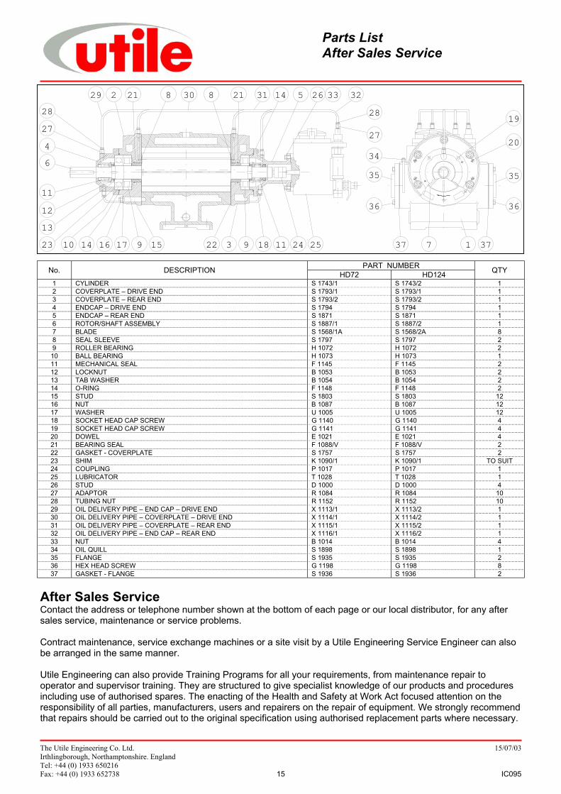
7. Spare PartsA stock of the main wearing parts at the installation site is important to the constant availability and smooth runningof the machine. We recommend the following parts and quantities to be kept in stock at the installation site.
Part NumberDescription HD72 HD124 Quantity
Blade S 1568/1 S 1568/2 8Roller Bearing – Drive & Rear End H 1072 H 1072 2Ball Bearing – Drive End H 1073 H 1073 1Mechanical Seal F 1145 F 1145 2Bearing Seal F 1088/V F 1088/V 2O-Ring F 1148 F 1148 2Gasket – Flange S 1936 S 1936 2Gasket – Coverplate S 1757 S 1757 2Drive Belt / Drive Coupling 1 set
Always quote the machine serial number when ordering spare parts.
Spare Parts
The Utile Engineering Co. Ltd. 15/07/03Irthlingborough, Northamptonshire. EnglandTel: +44 (0) 1933 650216Fax: +44 (0) 1933 652738 15 IC095
229 21 8 30 8 21 31 14 5 33 322628
27
282746
11121323 10 14 16 17 9 15 22 3 9 18 11 24 25 37 7 1 37
36
3534
19
36
35
20
PART NUMBERNo. DESCRIPTION HD72 HD124 QTY
1 CYLINDER S 1743/1 S 1743/2 12 COVERPLATE – DRIVE END S 1793/1 S 1793/1 13 COVERPLATE – REAR END S 1793/2 S 1793/2 14 ENDCAP – DRIVE END S 1794 S 1794 15 ENDCAP – REAR END S 1871 S 1871 16 ROTOR/SHAFT ASSEMBLY S 1887/1 S 1887/2 17 BLADE S 1568/1A S 1568/2A 88 SEAL SLEEVE S 1797 S 1797 29 ROLLER BEARING H 1072 H 1072 2
10 BALL BEARING H 1073 H 1073 111 MECHANICAL SEAL F 1145 F 1145 212 LOCKNUT B 1053 B 1053 213 TAB WASHER B 1054 B 1054 214 O-RING F 1148 F 1148 215 STUD S 1803 S 1803 1216 NUT B 1087 B 1087 1217 WASHER U 1005 U 1005 1218 SOCKET HEAD CAP SCREW G 1140 G 1140 419 SOCKET HEAD CAP SCREW G 1141 G 1141 420 DOWEL E 1021 E 1021 421 BEARING SEAL F 1088/V F 1088/V 222 GASKET - COVERPLATE S 1757 S 1757 223 SHIM K 1090/1 K 1090/1 TO SUIT24 COUPLING P 1017 P 1017 125 LUBRICATOR T 1028 T 1028 126 STUD D 1000 D 1000 427 ADAPTOR R 1084 R 1084 1028 TUBING NUT R 1152 R 1152 1029 OIL DELIVERY PIPE – END CAP – DRIVE END X 1113/1 X 1113/2 130 OIL DELIVERY PIPE – COVERPLATE – DRIVE END X 1114/1 X 1114/2 131 OIL DELIVERY PIPE – COVERPLATE – REAR END X 1115/1 X 1115/2 132 OIL DELIVERY PIPE – END CAP – REAR END X 1116/1 X 1116/2 133 NUT B 1014 B 1014 434 OIL QUILL S 1898 S 1898 135 FLANGE S 1935 S 1935 236 HEX HEAD SCREW G 1198 G 1198 837 GASKET - FLANGE S 1936 S 1936 2
After Sales ServiceContact the address or telephone number shown at the bottom of each page or our local distributor, for any aftersales service, maintenance or service problems.
Contract maintenance, service exchange machines or a site visit by a Utile Engineering Service Engineer can alsobe arranged in the same manner.
Utile Engineering can also provide Training Programs for all your requirements, from maintenance repair tooperator and supervisor training. They are structured to give specialist knowledge of our products and proceduresincluding use of authorised spares. The enacting of the Health and Safety at Work Act focused attention on theresponsibility of all parties, manufacturers, users and repairers on the repair of equipment. We strongly recommendthat repairs should be carried out to the original specification using authorised replacement parts where necessary.
Parts ListAfter Sales ServiceParts ListAfter Sales Service
The Utile Engineering Co. Ltd. 15/07/03Irthlingborough, Northamptonshire. EnglandTel: +44 (0) 1933 650216Fax: +44 (0) 1933 652738 16 IC095
Warranty Claim ConditionsUtile offers a 12-month warranty against faulty parts and workmanship. This does not include components used inthe production of packages, where the appropriate manufacturers warranty applies.1. The warranty period commences from the first day that the operator receives the machine.2. The warranty covers defective parts or workmanship used in the manufacture of the machine.3. The operator must notify the company promptly of any failure (using the appropriate procedure – indicated
below).
Please note: The company is not liable for any claim where: -1. Damages or delay or any other consequential cost associated with the alleged defect, are incurred.2. Malfunction caused by fair wear and tear, abnormal conditions of use, accident, neglect or misuse of
equipment, or improper storage.3. Deviation from operating specifications or other special terms of sale.4. Improper operation, maintenance or repair.5. Damage resulting during shipment or installation by other than company authorised personnel.6. Freight charges for goods returned to the company’s premises.
No allowances will be made for repairs or alterations carried out without the company’s written consent or approval.
Claim formTo make a claim complete the form below and send, phone, fax or email us at the address at the bottom of thepage.
Warranty Claim FormYour Details
Name:Company Name:Company Address:
Telephone:Fax:E-mail:
Machine DetailsSerial Number:Model:Site Location:Supplier Name:Installers Name:Date Commissioned:Name of Person responsible for Maintenance:Operating Hours a Day:
Duty DetailsSpeed: Gas Flow: Pressure:Further Information
Warranty


![OPTOMA HD72[1]](https://static.fdocuments.net/doc/165x107/577ce73f1a28abf10394aac1/optoma-hd721.jpg)