Installation, Operation, and Maintenance - Trane · Digit 21 - Communications Options3 0 No...
72
SAFETY WARNING Only qualified personnel should install and service the equipment. The installation, starting up, and servicing of heating, ventilating, and air-conditioning equipment can be hazardous and requires specific knowledge and training. Improperly installed, adjusted or altered equipment by an unqualified person could result in death or serious injury.When working on the equipment, observe all precautions in the literature and on the tags, stickers, and labels that are attached to the equipment. Packaged Rooftop Air Conditioners Precedent™- Electric/Electric 3 to 10Tons – 60 Hz Installation, Operation, and Maintenance Model Numbers: TSC037E - TSC067E THC036E - THC072E TSC036E - TSC060E THC120F TSC072F - TSC120F THC037E - THC067E THC048F - THC102F RT-SVX22P-EN April 2015
Transcript of Installation, Operation, and Maintenance - Trane · Digit 21 - Communications Options3 0 No...

SAFETY WARNINGOnly qualified personnel should install and service the equipment.The installation, starting up, and servicingof heating, ventilating, and air-conditioning equipment can be hazardous and requires specific knowledge andtraining. Improperly installed, adjusted or altered equipment by an unqualified person could result in death orserious injury. When working on the equipment, observe all precautions in the literature and on the tags,stickers, and labels that are attached to the equipment.
Packaged Rooftop Air Conditioners
Precedent™- Electric/Electric
3 to 10Tons – 60 Hz
Installation, Operation,
and Maintenance
Model Numbers: TSC037E - TSC067E THC036E - THC072ETSC036E - TSC060E THC120FTSC072F - TSC120F THC037E - THC067E
THC048F - THC102F
RT-SVX22P-ENApril 2015
Introduction
Read this manual thoroughly before operating or servicingthis unit.
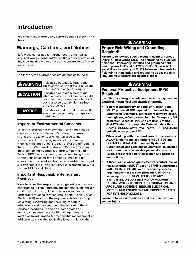
Warnings, Cautions, and Notices
Safety advisories appear throughout this manual asrequired.Your personal safety and the proper operation ofthis machine depend upon the strict observance of theseprecautions.
Important Environmental Concerns
Scientific research has shown that certain man-madechemicals can affect the earth’s naturally occurringstratospheric ozone layer when released to theatmosphere. In particular, several of the identifiedchemicals that may affect the ozone layer are refrigerantsthat contain Chlorine, Fluorine and Carbon (CFCs) andthose containing Hydrogen, Chlorine, Fluorine andCarbon (HCFCs). Not all refrigerants containing thesecompounds have the same potential impact to theenvironment.Trane advocates the responsible handling ofall refrigerants-including industry replacements for CFCssuch as HCFCs and HFCs.
Important Responsible RefrigerantPractices
Trane believes that responsible refrigerant practices areimportant to the environment, our customers, and the airconditioning industry. All technicians who handlerefrigerants must be certified.The Federal Clean Air Act(Section 608) sets forth the requirements for handling,reclaiming, recovering and recycling of certainrefrigerants and the equipment that is used in theseservice procedures. In addition, some states ormunicipalities may have additional requirements thatmust also be adhered to for responsible management ofrefrigerants. Know the applicable laws and follow them.
The three types of advisories are defined as follows:
WARNINGIndicates a potentially hazardoussituation which, if not avoided, couldresult in death or serious injury.
CAUTIONsIndicates a potentially hazardoussituation which, if not avoided, couldresult in minor or moderate injury. Itcould also be used to alert againstunsafe practices.
NOTICE Indicates a situation that could result inequipment or property-damage onlyaccidents.
WARNING
Proper Field Wiring and GroundingRequired!
Failure to follow code could result in death or seriousinjury. All field wiring MUST be performed by qualifiedpersonnel. Improperly installed and grounded fieldwiring poses FIRE and ELECTROCUTION hazards.Toavoid these hazards, you MUST follow requirements forfield wiring installation and grounding as described inNEC and your local/state electrical codes.
WARNING
Personal Protective Equipment (PPE)Required!
Installing/servicing this unit could result in exposure toelectrical, mechanical and chemical hazards.
• Before installing/servicing this unit, technicians
MUST put on all PPE required for the work being
undertaken (Examples; cut resistant gloves/sleeves,
butyl gloves, safety glasses, hard hat/bump cap, fall
protection, electrical PPE and arc flash clothing).
ALWAYS refer to appropriate Material Safety Data
Sheets (MSDS)/Safety Data Sheets (SDS) and OSHA
guidelines for proper PPE.
• When working with or around hazardous chemicals,
ALWAYS refer to the appropriate MSDS/SDS and
OSHA/GHS (Global Harmonized System of
Classification and Labelling of Chemicals) guidelines
for information on allowable personal exposure
levels, proper respiratory protection and handling
instructions.
• If there is a risk of energized electrical contact, arc, or
flash, technicians MUST put on all PPE in accordance
with OSHA, NFPA 70E, or other country-specific
requirements for arc flash protection, PRIOR to
servicing the unit. NEVER PERFORM ANY
SWITCHING, DISCONNECTING, OR VOLTAGE
TESTING WITHOUT PROPER ELECTRICAL PPE AND
ARC FLASH CLOTHING. ENSURE ELECTRICAL
METERS AND EQUIPMENT ARE PROPERLY RATED
FOR INTENDED VOLTAGE.
Failure to follow instructions could result in death orserious injury.
© 2015Trane All rights reserved RT-SVX22P-EN

Introduction
Copyright
This document and the information in it are the property ofTrane, and may not be used or reproduced in whole or inpart without written permission.Trane reserves the rightto revise this publication at any time, and to make changesto its content without obligation to notify any person ofsuch revision or change.
Trademarks
All trademarks referenced in this document are thetrademarks of their respective owners.
Revision History
RT-SVX22P-EN (27 April 2015)
• Updated IOM to include microchannel forTHC 10Ton
RT-SVX22P-EN 3

Table of Contents
Introduction . . . . . . . . . . . . . . . . . . . . . . . . . . . . . 2
Warnings, Cautions, and Notices . . . . . . . . 2
Important Environmental Concerns . . . . . 2
Important Responsible Refrigerant Practices2
Copyright . . . . . . . . . . . . . . . . . . . . . . . . . . . . . 3
Model Number Description . . . . . . . . . . . . . . . 6
Model Number Notes . . . . . . . . . . . . . . . . . 7
Model Number Description - 17 Plus . . . . . . 8
Model Number Notes . . . . . . . . . . . . . . . . . 9
General Information . . . . . . . . . . . . . . . . . . . . 10
Unit Inspection . . . . . . . . . . . . . . . . . . . . . 10
Storage . . . . . . . . . . . . . . . . . . . . . . . . . . . 10
Unit Nameplate . . . . . . . . . . . . . . . . . . . . 10
Compressor Nameplate . . . . . . . . . . . . . . 10
Microchannel Condenser Barcode ID . . . 10
Unit Description . . . . . . . . . . . . . . . . . . . . 10
Economizer Control Actuator (Optional) 10
System Input Devices & Functions . . . . . 11
Low Pressure Control . . . . . . . . . . . . . . . . 12
High Pressure Control . . . . . . . . . . . . . . . 12
Power Exhaust Control (Optional) . . . . . 12
Lead/Lag Control (Dual Circuit Only) . . . 12
Evaporator Frost Control . . . . . . . . . . . . . 13
Discharge Line Temp Switch (DLTS) . . . 14
Smoke Detector Sensor (Optional) . . . . . 14
Phase Monitor . . . . . . . . . . . . . . . . . . . . . 14
Single Zone Variable Air Volume / Displace-ment Ventilation (Optional) . . . . . . . . . . . 14
Human Interface - 5 Inch Color Touchscreen(Optional) . . . . . . . . . . . . . . . . . . . . . . . . . 14
Unit Dimensions . . . . . . . . . . . . . . . . . . . . . . . . 15
Unit Clearances . . . . . . . . . . . . . . . . . . . . . . 15
Installation . . . . . . . . . . . . . . . . . . . . . . . . . . . . . 22
Pre-Installation . . . . . . . . . . . . . . . . . . . . . . . 22
Procedure . . . . . . . . . . . . . . . . . . . . . . . . . . . 22
Foundation . . . . . . . . . . . . . . . . . . . . . . . . . . 24
Horizontal Units . . . . . . . . . . . . . . . . . . . . .24
Ductwork . . . . . . . . . . . . . . . . . . . . . . . . . . . . .25
Roof Curb . . . . . . . . . . . . . . . . . . . . . . . . . .26
Rigging . . . . . . . . . . . . . . . . . . . . . . . . . . . .27
General Unit Requirements . . . . . . . . . . . . .28
Factory Installed Economizer . . . . . . . . . .28
Temperature Limit Switch Usage for ElectricHeat Units . . . . . . . . . . . . . . . . . . . . . . . . . .28
Horizontal Discharge Conversion (3 to 5 TonUnits) . . . . . . . . . . . . . . . . . . . . . . . . . . . . . . . .28
Horizontal Discharge Conversion (6 to 10 TonUnits) . . . . . . . . . . . . . . . . . . . . . . . . . . . . . . . .28
TCO-A Instructions . . . . . . . . . . . . . . . . . . .29
Return Air Smoke Detector . . . . . . . . . . . . .30
Main Electrical Power Requirements . . . . .31
Electric Heat Requirements . . . . . . . . . . . .31
Low Voltage Wiring(AC & DC) Requirements . . . . . . . . . . . . . .31
Condensate Drain Configuration . . . . . . . . .32
Filter Installation . . . . . . . . . . . . . . . . . . . . . .32
Field Installed Power Wiring . . . . . . . . . . . .33
Main Unit Power . . . . . . . . . . . . . . . . . . . . . .33
Standard Wiring . . . . . . . . . . . . . . . . . . . . .33
Optional TBUE Wiring (Through-the-BaseElectrical Option) . . . . . . . . . . . . . . . . . . . .33
Field Installed Control Wiring . . . . . . . . . .34
Control Power Transformer . . . . . . . . . . .34
Controls using 24 VAC . . . . . . . . . . . . . . . .34
Controls using DC AnalogInput/Outputs (Standard Low Voltage Multiconductor Wire) . . . . . . . . . . . . . . . . . . . . .35
DC Conductors . . . . . . . . . . . . . . . . . . . . . .35
Space Temperature Averaging (ReliaTel™ on-ly) . . . . . . . . . . . . . . . . . . . . . . . . . . . . . . . . . . .40
Pre-Start . . . . . . . . . . . . . . . . . . . . . . . . . . . . . . . .43
Voltage Imbalance . . . . . . . . . . . . . . . . . . . . .43
Electrical Phasing (Three Phase Motors) . .43
Compressor Crankcase Heaters (Optional) 44
ReliaTel™ Controls . . . . . . . . . . . . . . . . . .44
4 RT-SVX22P-EN

Table of Contents
Test Modes . . . . . . . . . . . . . . . . . . . . . . . . . . 45
Electromechanical ControlsTest Procedure . . . . . . . . . . . . . . . . . . . . . 45
Unit Start-Up . . . . . . . . . . . . . . . . . . . . . . . . . . . 46
Verifying Proper Air Flow . . . . . . . . . . . . . . 46
Units with 5-Tap Direct Drive Indoor Fan 46
Units with Belt Drive Indoor Fan . . . . . . . 46
Units with Direct Drive Indoor Fan - Electro-mechanical Control . . . . . . . . . . . . . . . . . 47
ReliaTel™ Units with Direct Drive Indoor Fan(10 Ton Standard Efficiency, 7½ to 10 TonHigh Efficiency) . . . . . . . . . . . . . . . . . . . . . 47
Units with Constant CFM Direct Drive IndoorFan . . . . . . . . . . . . . . . . . . . . . . . . . . . . . . . 48
17 Plus units with the constant CFM directdrive indoor fan . . . . . . . . . . . . . . . . . . . . 48
Variable Air Volume Applications (TraditionalVAV) . . . . . . . . . . . . . . . . . . . . . . . . . . . . . . 49
Supply Duct Static Pressure Control . . . . 50
Traditional VAV Standalone Operation . 50
Supply Air Temperature Reset . . . . . . . . 50
Return Air Smoke Detector . . . . . . . . . . . 51
Economizer Start-Up . . . . . . . . . . . . . . . . 51
Compressor Start-Up . . . . . . . . . . . . . . . . 52
Dehumidification Option . . . . . . . . . . . . . 52
Final System Setup . . . . . . . . . . . . . . . . . 53
Maintenance . . . . . . . . . . . . . . . . . . . . . . . . . . . 54
Fan Belt Adjustment - Belt Drive Units . . . 54
Monthly Maintenance . . . . . . . . . . . . . . . . . 55
Filters . . . . . . . . . . . . . . . . . . . . . . . . . . . . . 55
Return Air Smoke Detector Maintenance 55
Cooling Season . . . . . . . . . . . . . . . . . . . . 55
Heating Season . . . . . . . . . . . . . . . . . . . . 55
Coil Cleaning . . . . . . . . . . . . . . . . . . . . . . . 55
Microchannel (MCHE) Coils . . . . . . . . . . . 56
Round Tube Plate Fin (RTPF) Coils . . . . . 56
Annual Maintenance . . . . . . . . . . . . . . . . . . 58
Final Process . . . . . . . . . . . . . . . . . . . . . . . . . 58
Troubleshooting . . . . . . . . . . . . . . . . . . . . . . . . 59
ReliaTel™ Control . . . . . . . . . . . . . . . . . . . . 59
System Status Checkout Procedure . . . . . 59
Method 1 . . . . . . . . . . . . . . . . . . . . . . . . . . .59
Resetting Cooling and Ignition Lockouts .60
Zone Temperature Sensor (ZTS) Service Indi-cator . . . . . . . . . . . . . . . . . . . . . . . . . . . . . . . . .61
Clogged Filter Switch . . . . . . . . . . . . . . . . .61
Fan Failure Switch . . . . . . . . . . . . . . . . . . .61
Condensate Overflow Switch . . . . . . . . . .61
Zone Temperature Sensor (ZTS) Test . . . .61
Test 1 - Zone Temperature Thermistor(ZTEMP) . . . . . . . . . . . . . . . . . . . . . . . . . . .61
Test 2 - Cooling Set Point (CSP) and HeatingSet Point (HSP) . . . . . . . . . . . . . . . . . . . . . .61
Test 3 - System Mode and Fan Selection .61
Test 4 - LED Indicator Test, (SYS ON, HEAT,COOL & SERVICE) . . . . . . . . . . . . . . . . . . .61
Relative Humidity Sensor Test . . . . . . . . .62
Programmable & Digital ZoneSensor Test . . . . . . . . . . . . . . . . . . . . . . . . .62
ReliaTel™ Refrigeration Module (RTRM) De-fault Chart . . . . . . . . . . . . . . . . . . . . . . . . . .62
Unit Operation without a Zone Sensor . .62
Unit Economizer Control (ECA) Troubleshoot-ing . . . . . . . . . . . . . . . . . . . . . . . . . . . . . . . . . . .62
ReliaTel™ Control . . . . . . . . . . . . . . . . . . .62
Electromechanical Control . . . . . . . . . . . .63
Unit Economizer Control (ECA) Test Proce-dures . . . . . . . . . . . . . . . . . . . . . . . . . . . . . . . .64
Electromechanical Control . . . . . . . . . . . .64
Troubleshooting procedures for Direct DrivePlenum Fan . . . . . . . . . . . . . . . . . . . . . . . . . . .65
Unit Wiring Diagrams Numbers . . . . . . . . . . .66
Limited Warranty . . . . . . . . . . . . . . . . . . . . . . . .68
Electric Air Conditioner . . . . . . . . . . . . . . . . .68
TCY, TCX, TCC, TCD, TCH, TCM,TCP, TSC andTHC (Parts Only) Models Less Than 20 Tonsfor Residential Use* . . . . . . . . . . . . . . . . . .68
Electric Air Conditioner . . . . . . . . . . . . . . . . .69
TCY, TCX, TCC, TCD, TCH, TCK, TCM, TCP,TSC and THC (Parts Only) Models Less Than20 Tons for Commercial Use* . . . . . . . . . .69
RT-SVX22P-EN 5

Model Number Description
Digit 1 - UnitTypeT DX Cooling
Digit 2 - EfficiencyS Standard EfficiencyH High Efficiency
Digit 3 - AirflowC Convertible
Digit 4,5,6 - Nominal GrossCooling Capacity (MBh)036 3Ton048 4Ton060 5Ton072 6Ton090 7½Ton, Single Compressor092 7½Ton, Dual Compressor102 8½Ton120 10Ton
Digit 7 - Major Design SequenceE R-410A RefrigerantF MicrochannelType Condenser
Coils23
Digit 8 - Voltage Selection1 208/230/60/13 208-230/60/34 460/60/3W 575/60/3
Digit 9 - Unit ControlsE ElectromechanicalR ReliaTel™ Microprocessor
Digit 10 - Heating Capacity
Digit 11 - Minor DesignSequenceA First Sequence20
B Second Sequence19
Digit 12,13 - Service Sequence** Factory Assigned
Digit 14 - Fresh Air Selection0 No Fresh AirA Manual Outside Air Damper 0-50%4
B Motorized Outside Air Damper0-50%27
C Economizer, Dry Bulb 0-100%without Barometric Relief7
D Economizer, Dry Bulb 0-100%with Barometric Relief7
E Economizer, Reference Enthalpy0-100% without Barometric Relief3,7
F Economizer, Reference Enthalpy0-100% with Barometric Relief3,7
G Economizer, ComparativeEnthalpy 0-100% withoutBarometric Relief3,7
H Economizer, Comparative
Enthalpy 0-100% with BarometricRelief3,7
K Low Leak Economizer withBarometric Relief
M Low Leak Economizer with ReferenceEnthalpy with Barometric Relief
P Low Leak Economizer withComparative Enthalpy withBarometric Relief
Digit 15 - Supply Fan/DriveType/Motor0 Standard Drive6
1 Oversized Motor2 Optional Belt Drive Motor17
6 Single Zone Variable Air Volume25
7 Multi-Speed Indoor Fan26
E VAV Supply AirTemperature ControlStandard Motor32
Digit 16 - Hinged ServiceAccess/Filters0 Standard Panels/Standard FiltersA Hinged Access Panels/Standard
FiltersB Standard Panels/2” MERV 8 FiltersC Hinged Access Panels/2” MERV 8
FiltersD Standard Panels/2” MERV 13 FiltersE Hinged Access Panels/2” MERV 13
Filters
Digit 17 - Condenser CoilProtection0 Standard Coil1 Standard Coil with Hail Guard2 Black Epoxy Pre-Coated Condenser
Coil24
3 Black Epoxy Pre-CoatedCondenser Coil with Hail Guard24
4 CompleteCoat™ Condenser Coil5 CompleteCoat™ Condenser Coil
with Hail Guard
Digit 18 -Through the BaseProvisions0 NoThrough-the-Base ProvisionsA Through-the-Base Electric8
Digit 19 - Disconnect/CircuitBreaker (three-phase only)0 No Disconnect/No Circuit Breaker1 Unit Mounted Non-Fused
Disconnect82 Unit Mounted Circuit Breaker8
Digit 20 - Convenience Outlet0 No Convenience OutletA Unpowered Convenience OutletB Powered Convenience Outlet
(three-phase only)9
Digit 21 - CommunicationsOptions3
0 No Communications Interface1 Trane Communications Interface2 LonTalk® Communications Interface3 Novar 2024 Controls29
4 Novar 3051 Controls without ZoneSensor29
5 Novar 3051Controls Interface withDCV29
6 BACnet® Communications Interface
Digit 22 - Refrigeration SystemOption0 Standard Refrigeration System10
B Dehumidification Option21,22
Digit 23 - Refrigeration ControlsNote: Applicable to Digit 7 = E, F0 No Refrigeration Control51 Frostat11,28
2 Crankcase Heater2
3 Frostat™11,28 and Crankcase Heater2
Digit 24 - Smoke Detector16
0 No Smoke DetectorA Return Air Smoke Detector12,13
B Supply Air Smoke DetectorC Supply and Return Air Smoke
Detectors12,13
D Plenum Smoke Detector
Digit 25 - System MonitoringControls0 No Monitoring Control14
1 Clogged Filter Switch14
2 Fan Failure Switch14
3 Discharge Air SensingTube14
4 Clogged Filter Switch and FanFailure Switch14
5 Clogged Filter Switch and DischargeAir SensingTube14
6 Fan Failure Switch and Discharge AirSensingTube14
7 Clogged Filter Switch, Fan FailureSwitch and Discharge AirSensingTube14
8 Novar Return Air Sensor(NOVAR 2024)15,29
9 Novar ZoneTemp Sensor(NOVAR 3051)18,29
A Condensate Drain Pan OverflowSwitch
B Clogged Filter Switch14 andCondensate Drain Pan OverflowSwitch
C Fan Failure Switch14 and CondensateDrain Pan Overflow Switch
D Discharge Air Sensing14 andCondensate Drain Pan OverflowSwitch
E Clogged Filter Switch14, Fan FailureSwitch14 and Condensate Drain PanOverflow Switch
F Clogged Filter Switch14, DischargeAir SensingTube14 and CondensateDrain Pan Overflow Switch
T S C 0 3 6 E 3 R B A * *
1 2 3 4 5 6 7 8 9 10 11 12 13
0=No Electric Heat F=14 kW (1 phase)1
A=5 kW (1 phase)1 G=18 kW (1&3 phase)B=6 kW (3 phase) J=23 kW (3 phase)C=9 kW (3 phase) K= 27 kW (3 phase)D=10 kW (1 phase)1 N = 36 kW (3 phase)E=12 kW (3 phase) P = 54 kW (3 phase)
6 RT-SVX22P-EN

Model Number Description
G Fan Failure Switch, Discharge AirSensingTube14 and CondensateDrain Pan Overflow Switch
H Clogged Filter Switch14, Fan FailureSwitch14, Discharge Air Sensing14
and Condensate Drain Pan OverflowSwitch
Digit 26 - System MonitoringControls0 No Monitoring ControlsA Demand Control Ventilation
(CO2)30,31
B Low Leak Economizer with FDD(Fault Detection & Diagnostics)
C FDD (Fault Detection & Diagnostics)with DCV (Demand ControlVentilation)
Digit 27 - Unit HardwareEnhancements0 No Enhancements1 Stainless Steel Drain Pan
Digit 31- Advanced UnitControls0 Standard Unit Controls1 Human Interface
Model Number Notes
1. Available on 3-5 ton models.
2. Crankcase heaters are optionalonTSC (036, 048, 060, 072, 090,102, 120); standard onTHC (036,048, 060, 072, 092, 102, 120).
3. Not available withelectromechanical controls.
4. Manual outside air damper willship factory supplied within theunit, but must be field installed.
5. High pressure control is standardon all units.
6. On 3-5 ton, multispeed directdrive is standard on single phaseand 15 SEER. On 6-10 ton,multispeed direct drive isstandard on all 10 ton and 7.5-8.5ton high efficiency. Belt drive isstandard on all other units.
7. Economizer with BarometricRelief is for downflow configuredunits only. Order Economizerwithout Barometric Relief forhorizontal configuration.Barometric Relief for horizontalconfigured units must be orderedas field installed accessory.
8. Through the base electricrequired when orderingdisconnect/circuit breakeroptions.
9. Requires use of Disconnect orCircuit Breaker.
10. Standard metering devices areTXVs.
11. Frostat cannot be field installed inelectro-mechanical units.
12. The return air smoke detectormay not fit up or work properly onthe Precedent units when used inconjunction with 3rd partyaccessories such as bolt on heatwheels, economizers and powerexhaust. Do not order the returnair smoke detectors when usingthis type of accessory.
13. Return Air Smoke Detectorcannot be ordered with NovarControls.
14. These options are standard whenordering Novar Controls.
15. This option is used whenordering Novar Controls.
16. Not available with hightemperature duct sensoraccessory.
17. Digit 15 = 2
18. Novar Sensor utilized withDigit 21 = (4) Novar 3051 Controlswithout Zone Sensor.
19. Available for 10 ton standardefficiency models only.
20. Available for 3, 4, 5, 6, 7½, 8½ tonstandard/high efficiency modelsonly.
21. Requires selection of 2” PleatedFilters (option B or C) for Digit 16.
22. Not available on 6 ton units andall single phase or standardefficiency.
23. Standard onTSC 6, 7½ (singleand dual systems), 8½, 10 tonstandard efficiency models andTHC 4, 5, 6, 7½, 8½, 10 ton highefficiency models (except for 3, 4,5, 6 and 10 ton dehumidificationmodels).
24. Epoxy coil and epoxy withhailguard options are notavailable for units withmicrochannel condenser coil.
25. Single ZoneVAV is only availableon 7.5-10 ton high efficiency and10 ton standard efficiencyproductswith ReliaTel™controls.
26. Multi-speed indoor fan availableonly on 7.5 & 8.5 ton highefficiency, and 10 ton productswith ReliaTel™ controls.
27. Motorized Outside Air Damper isnot available on Multi-Speed orSZVAV (Single Zone Variable AirVolume) products.
28. Frostat standard on Multi-Speedand SZVAV (Single ZoneVariableAir Volume) products.
29. Novar isnotavailablewithSZVAVproducts.
30. Demand Control Ventilation notavailable with electromechanicalcontrols.
31. Demand Control VentilationOption includes wiring only.TheC02 sensor is a field-installed onlyoption.
32. Discharge Air Sensing is alsostandard equipment on unitswith Single Zone and Supply AirTemperature Control VAV.
Digit 15 = 0Standard Efficiency1 Phase = High Efficiency Multispeed Direct Drive Motor3 Phase (3-8½ Ton) = Belt Drive3 Phase (10 Ton) = Ultra High Efficiency Direct Drive Plenum FanHigh Efficiency1 Phase = High Efficiency Multispeed Direct Drive Motor3 Phase (3-5 ton) = High Efficiency Multispeed Direct Drive Motor3 Phase (3-5 ton w/Dehumidification) = Belt Drive Motor3 Phase (7½-10 ton) = Ultra High Efficiency Direct Drive Plenum Fan
Not AvailableStandard Efficiency10 Ton w/575VHigh Efficiency3-5 ton w/Standard Indoor Motor w/460V
Standard Efficiency1 Phase = Not Available3 Phase = Not AvailableHigh Efficiency1 Phase = Not Available3 Phase (3-5 ton) = May be Ordered3 Phase (3-5 ton w/Dehumidification) = Not Available3 Phase (6-10 ton) = Not Available
RT-SVX22P-EN 7

Model Number Description - 17 Plus
Model Number Description - 17 Plus
Digit 1 - UnitTypeT DX CoolingY DX Cooling, Gas Heat
Digit 2 - EfficiencyS Standard EfficiencyH High Efficiency
Digit 3 - AirflowC Convertible
Digit 4,5,6 - Nominal GrossCooling Capacity (MBh)037 3Ton047 4Ton067 5Ton
Digit 7 - Major Design SequenceE R-410A Refrigerant
Digit 8 - Voltage Selection3 208-230/60/34 460/60/3
Digit 9 - Unit ControlsR ReliaTel™ Microprocessor
Digit 10 - Heating Capacity
L Low HeatM Medium HeatH High HeatX Low Heat, Stainless Steel Heat
ExchangerY Medium Heat, Stainless Steel Heat
ExchangerZ High Heat, Stainless Steel Heat
Exchanger
Digit 11 - Minor DesignSequenceA First Sequence16
Digit 12,13 - Service Sequence** Factory Assigned
Digit 14 - Fresh Air Selection0 No Fresh AirA Manual Outside Air Damper 0-50%2
B Motorized Outside Air Damper0-50%
C Economizer, Dry Bulb 0-100%without Barometric Relief5
D Economizer, Dry Bulb 0-100%with Barometric Relief5
E Economizer, Reference Enthalpy0-100% without Barometric Relief5
F Economizer, Reference Enthalpy0-100% with Barometric Relief5
G Economizer, ComparativeEnthalpy 0-100% withoutBarometric Relief5
H Economizer, ComparativeEnthalpy 0-100% with BarometricRelief5
K Low Leak Economizer withBarometric Relief
M Low Leak Economizer with ReferenceEnthalpy with Barometric Relief
P Low Leak Economizer withComparative Enthalpy withBarometric Relief
Digit 15 - Supply Fan/DriveType/Motor0 Standard Drive4
6 Single Zone VAV21
E VAV Supply AirTemperature ControlStandard Motor21
Digit 16 - Hinged ServiceAccess/Filters0 Standard Panels/Standard FiltersA Hinged Access Panels/Standard
FiltersB Standard Panels/2” MERV 8 FiltersC Hinged Access Panels/2” MERV 8
FiltersD Standard Panels/2” MERV 13 FiltersE Hinged Access Panels/2” MERV 13
Filters
Digit 17 - Condenser CoilProtection0 Standard Coil1 Standard Coil with Hail Guard2 Black Epoxy Pre-Coated Condenser
Coil3 Black Epoxy Pre-Coated
Condenser Coil with Hail Guard4 CompleteCoat™ Condenser Coil5 CompleteCoat™ Condenser Coil
with Hail Guard
Digit 18 -Through the BaseProvisions0 NoThrough-the-Base ProvisionsA Through-the-Base Electric6
B Through-the-Base Gas Piping13
C Through-the-Base Electric and GasPiping13
Digit 19 - Disconnect/CircuitBreaker (three-phase only)0 No Disconnect/No Circuit Breaker1 Unit Mounted Non-Fused
Disconnect62 Unit Mounted Circuit Breaker6
Digit 20 - Convenience Outlet0 No Convenience OutletA Unpowered Convenience OutletB Powered Convenience Outlet
(three-phase only)7
Digit 21 - CommunicationsOptions0 No Communications Interface3 Novar 2024 Controls4 Novar 3051 Controls without Zone
Sensor5 Novar 3051Controls Interface with
DCV6 BACnet® Communications Interface
Digit 22 - Refrigeration SystemOption0 Standard Refrigeration System8
B Dehumidification Option17
Digit 23 - Refrigeration ControlsNote: Applicable to Digit 7 = E0 No Refrigeration Control31 Frostat™2 Crankcase Heater1
3 Frostat™ and Crankcase Heater1
Digit 24 - Smoke Detector14
0 No Smoke DetectorA Return Air Smoke Detector9,10
B Supply Air Smoke DetectorC Supply and Return Air Smoke
Detectors9,10
D Plenum Smoke Detector
Digit 25 - System MonitoringControls0 No Monitoring Control11
1 Clogged Filter Switch11
2 Fan Failure Switch11
3 Discharge Air SensingTube11
4 Clogged Filter Switch and FanFailure Switch11
5 Clogged Filter Switch and DischargeAir SensingTube11
6 Fan Failure Switch and Discharge AirSensingTube11
7 Clogged Filter Switch, Fan FailureSwitch and Discharge AirSensingTube11
8 Novar Return Air Sensor(NOVAR 2024)12,20
9 Novar ZoneTemp Sensor(NOVAR 3051)15,20
A Condensate Drain Pan OverflowSwitch
B Clogged Filter Switch11 andCondensate Drain Pan OverflowSwitch
C Fan Failure Switch11 and CondensateDrain Pan Overflow Switch
D Discharge Air Sensing11 andCondensate Drain Pan OverflowSwitch
E Clogged Filter Switch11, Fan FailureSwitch11 and Condensate Drain PanOverflow Switch
T H C 0 3 7 E 3 R Z B * *
1 2 3 4 5 6 7 8 9 10 11 12 13
0=No Electric Heat G=18 kW (1&3 phase)B=6 kW (3 phase) J=23 kW (3 phase)E=12 kW (3 phase)
8 RT-SVX22P-EN
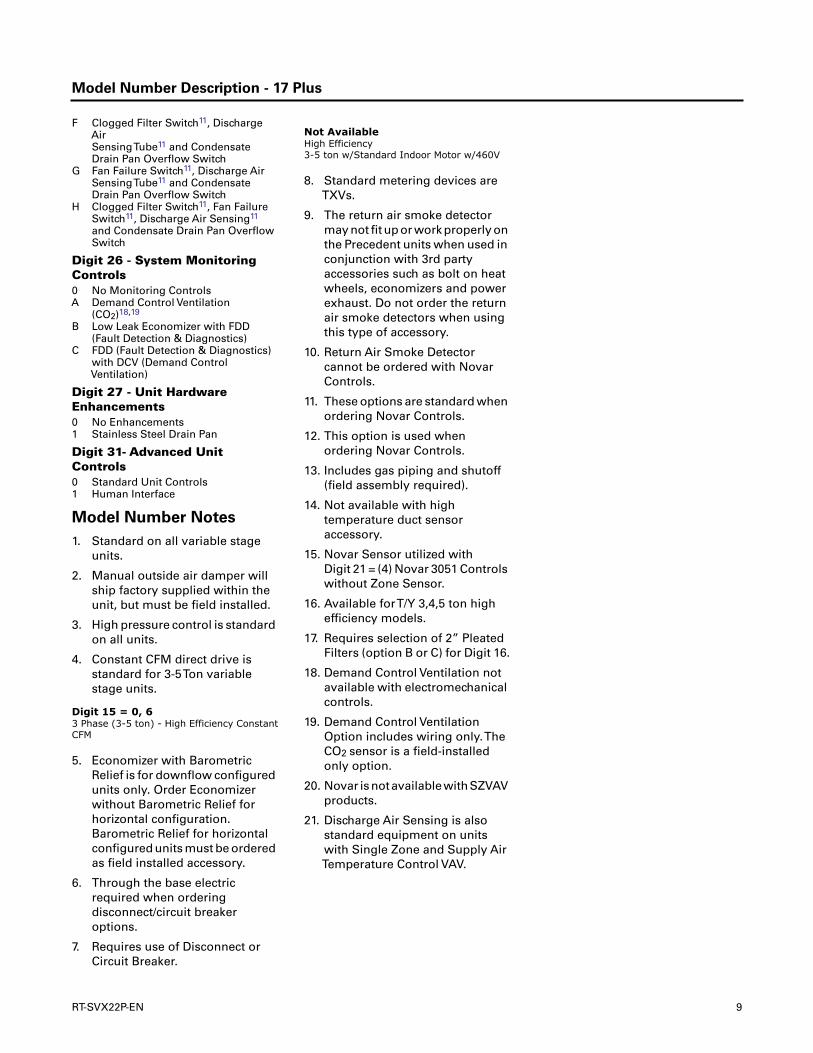
Model Number Description - 17 Plus
F Clogged Filter Switch11, DischargeAirSensingTube11 and CondensateDrain Pan Overflow Switch
G Fan Failure Switch11, Discharge AirSensingTube11 and CondensateDrain Pan Overflow Switch
H Clogged Filter Switch11, Fan FailureSwitch11, Discharge Air Sensing11
and Condensate Drain Pan OverflowSwitch
Digit 26 - System MonitoringControls0 No Monitoring ControlsA Demand Control Ventilation
(CO2)18,19
B Low Leak Economizer with FDD(Fault Detection & Diagnostics)
C FDD (Fault Detection & Diagnostics)with DCV (Demand ControlVentilation)
Digit 27 - Unit HardwareEnhancements0 No Enhancements1 Stainless Steel Drain Pan
Digit 31- Advanced UnitControls0 Standard Unit Controls1 Human Interface
Model Number Notes
1. Standard on all variable stageunits.
2. Manual outside air damper willship factory supplied within theunit, but must be field installed.
3. High pressure control is standardon all units.
4. Constant CFM direct drive isstandard for 3-5Ton variablestage units.
5. Economizer with BarometricRelief is for downflow configuredunits only. Order Economizerwithout Barometric Relief forhorizontal configuration.Barometric Relief for horizontalconfigured units must be orderedas field installed accessory.
6. Through the base electricrequired when orderingdisconnect/circuit breakeroptions.
7. Requires use of Disconnect orCircuit Breaker.
8. Standard metering devices areTXVs.
9. The return air smoke detectormay not fit up or work properly onthe Precedent units when used inconjunction with 3rd partyaccessories such as bolt on heatwheels, economizers and powerexhaust. Do not order the returnair smoke detectors when usingthis type of accessory.
10. Return Air Smoke Detectorcannot be ordered with NovarControls.
11. These options are standard whenordering Novar Controls.
12. This option is used whenordering Novar Controls.
13. Includes gas piping and shutoff(field assembly required).
14. Not available with hightemperature duct sensoraccessory.
15. Novar Sensor utilized withDigit 21 = (4) Novar 3051 Controlswithout Zone Sensor.
16. Available forT/Y 3,4,5 ton highefficiency models.
17. Requires selection of 2” PleatedFilters (option B or C) for Digit 16.
18. Demand Control Ventilation notavailable with electromechanicalcontrols.
19. Demand Control VentilationOption includes wiring only.TheCO2 sensor is a field-installedonly option.
20. Novar isnotavailablewithSZVAVproducts.
21. Discharge Air Sensing is alsostandard equipment on unitswith Single Zone and Supply AirTemperature Control VAV.
Digit 15 = 0, 63 Phase (3-5 ton) - High Efficiency Constant CFM
Not Available High Efficiency3-5 ton w/Standard Indoor Motor w/460V
RT-SVX22P-EN 9
General Information
Unit Inspection
As soon as the unit arrives at the job site
• Verify that the nameplate data matches the data on thesales order and bill of lading (including electrical data).
• Verify that the power supply complies with the unitnameplate specifications.
• Visually inspect the exterior of the unit, including theroof, for signs of shipping damage.
If the job site inspection of the unit reveals damage ormaterial shortages, file a claim with the carrierimmediately. Specify the type and extent of the damage onthe “bill of lading” before signing.
• Visually inspect the internal components for shippingdamage as soon as possible after delivery and beforeit is stored. Do not walk on the sheet metal base pans.
• If concealed damage is discovered, notify the carrier’sterminal of damage immediately by phone and bymail. Concealed damage must be reported within 15days.
• Request an immediate joint inspection of the damageby the carrier and the consignee. Do not removedamaged material from the receiving location.Takephotos of the damage, if possible.The owner mustprovide reasonable evidence that the damage did notoccur after delivery.
• Notify the appropriate sales representative beforeinstalling or repairing a damaged unit.
Storage
Take precautions to prevent condensate from forminginside the unit’s electrical compartments and motors if:
1. the unit is stored before it is installed; or,
2. the unit is set on the roof curb, and temporary heat isprovided in the building. Isolate all side panel serviceentrances and base pan openings (e.g., conduit holes,Supply Air and Return Air openings, and flueopenings) from the ambient air until the unit is readyfor start-up.
Note: Do not use the unit’s heater for temporary heatwithout first completing the start-up proceduredetailed under “Unit Start-Up,” p. 46”.
The manufacturer will not assume any responsibility forequipment damage resulting from condensateaccumulation on the unit’s electrical and/or mechanicalcomponents.
Unit Nameplate
A Mylar unit nameplate is located on the unit’s cornersupport next to the filter access panel. It includes the unitmodel number, serial number, electrical characteristics,refrigerant charge, as well as other pertinent unit data.
Compressor Nameplate
The nameplate for the compressors are located on the sideof the compressor.
Microchannel Condenser Barcode ID
Barcode decal used for condenser coil part identificationcan be located on the vertical header and top of coil's inlet/outlet side.
Unit Description
Before shipment, each unit is leak tested, dehydrated,charged with refrigerant and compressor oil, and runtested for proper control operation.
The condenser coils are either aluminum fin, mechanicallybonded to copper tubing or all aluminum microchannel.
Direct-drive, vertical discharge condenser fans areprovided with built-in thermal overload protection.
There are two control systems offered for these units.Theelectromechanical control option uses a thermostat toperform unit functions.The ReliaTel™ Control Module is amicroelectronic control system that is referred to as“Refrigeration Module” (RTRM).The acronym RTRM isused extensively throughout this document whenreferring to the control system network.
These modules through Proportional/Integral controlalgorithms perform specific unit functions that governsunit operation in response to; zone temperature, supply airtemperature, and/or humidity conditions depending onthe application.The stages of capacity control for theseunits are achieved by starting and stopping thecompressors.
The RTRM is mounted in the control panel and is factorywired to the respective internal components.The RTRMreceives and interprets information from other unitmodules, sensors, remote panels, and customer binarycontacts to satisfy the applicable request for cooling.
Economizer Control Actuator (Optional)
Electromechanical Control
The ECA monitors the mixed air temperature, ambient drybulb temperature and local minimum position setpointsensors, if selected, to control dampers to an accuracy of+/- 5% of stroke.The actuator is spring returned to theclosed position any time that power is lost to the unit. It iscapable of delivering up to 25 inch pounds of torque andis powered by 24 VAC.
ReliaTel™ Control
The ECA monitors the mixed air temperature, return airtemperature, minimum position setpoint (local orremote), power exhaust setpoint, CO2 setpoint, CO2, andambient dry bulb/enthalpy sensor or comparativehumidity (return air humidity against ambient humidity)
10 RT-SVX22P-EN

General Information
sensors, if selected, to control dampers to an accuracy of+/- 5% of stroke.The actuator is spring returned to theclosed position any time that power is lost to the unit. It iscapable of delivering up to 25 inch pounds of torque andis powered by 24 VAC.
RTCI - ReliaTel™Trane Communication
Interface (Optional)
This module is used when the application calls for anICSTM building management type control system. Itallows the control and monitoring of the system throughan ICS panel.The module can be ordered from the factoryor ordered as a kit to be field installed. Follow theinstallation instruction that ships with each kit when fieldinstallation is necessary.
RLCI - ReliaTel™ LonTalk Communication
Interface (Optional)
This module is used when the application calls for anICSTM building management type control system that isLonTalk. It allows the control and monitoring of the systemthrough an ICS panel.The module can be ordered from thefactory or ordered as a kit to be field installed. Follow theinstallation instruction that ships with each kit when fieldinstallation is necessary.
RBCI - ReliaTel™ BACnet® Communications
Interface (Optional)
This module is used when the application calls for an openBACnet protocol. It allows the control and monitoring ofthe system through an ICS panel.The module can beordered from the factory or as a kit to be field installed.Follow the installation instructions that ships with each kitwhen field installation is necessary.
RTOM - ReliaTel™ Options Module (Standard
on 17 Plus, 7.5Ton & 8.5Ton High Efficiency
with ReliaTel, 10Ton with ReliaTel)
The RTOM monitors the supply fan proving, clogged filter,supply air temperature, exhaust fan setpoint, supply airtempering, Frostat™, smoke detector, andVariable SpeedFan Control (17 Plus units only). Refer to system inputdevices and functions for operation.
System Input Devices & Functions
The RTRM must have a zone sensor or thermostat input inorder to operate the unit.The flexibility of having severalmode capabilities depends upon the type of zone sensor orthermostat selected to interface with the RTRM.
The descriptions of the following basic Input Devices usedwithin the RTRM network are to acquaint the operator withtheir function as they interface with the various modules.Refer to the unit’s electrical schematic for the specificmodule connections.
The following controls are available from the factory forfield installation.
Supply Fan Failure Input (Optional)
The Fan Failure Switch can be connected to sense indoorfan operation:
FFS (Fan Failure Switch) If air flow through the unit is notproven by the differential pressure switch connected to theRTOM (factory set point 0.07 “w.c.) within 40 secondsnominally, the RTRM will shut off all mechanicaloperations, lock the system out, send a diagnostic to ICS,and the SERVICE output will flash.The system will remainlocked out until a reset is initiated either manually orthrough ICS.
Clogged Filter Switch (Optional)
The unit mounted clogged filter switch monitors thepressure differential across the return air filters. It ismounted in the filter section and is connected to theRTOM. A diagnostic SERVICE signal is sent to the remotepanel if the pressure differential across the filters is at least0.5" w.c.The contacts will automatically open when thepressure differential across the filters decreases toapproximately 0.4" w.c.The clogged filter output isenergized when the supply fan is operating and theclogged filter switch has been closed for at least 2 minutes.The system will continue to operate regardless of thestatus of the filter switch.
Note: On units equipped with factory installed MERV 13filters, a clogged filter switch with differentpressure settings will be installed.This switch willclose when the differential pressure isapproximately 0.8' w.c. and open when thedifferential falls to 0.7" w.c.
Condensate Drain Pan Overflow Switch
(Optional)
ReliaTel Option
This input incorporates the Condensate Overflow Switch(COF) mounted on the drain pan and the ReliaTel OptionsModule (RTOM). When the condensate level reaches thetrip point for 6 continuous seconds, the RTOM will shutdown all unit functions until the overflow condition hascleared.The unit will return to normal operation after 6continuous seconds with the COF in a non-trippedcondition. If the condensate level causes unit shutdownmore than 2 times in a 3 days period, the unit will belocked-out of operation requiring manual reset ofdiagnostic system through Zone Sensor or BuildingAutomation System (BAS). Cycling unit power will alsoclear the fault.
Electromechanical Option
This input incorporates the condensate overflow switch(COF), COF Relay, COFTime Delay. When the condensatelevel reaches the trip point, the COF relay energizes andopens the 24VAC control circuit which disables the unit.Once the 24VAC control circuit is opened, a delay timer willprevent unit start-up for three minutes.
RT-SVX22P-EN 11
General Information
Compressor Disable (CPR1/2)
This input incorporates the low pressure control (LPC) ofeach refrigeration circuit and can be activated by openinga field supplied contact installed on the LTB.
If this circuit is open before the compressor is started, thecompressor will not be allowed to operate. Anytime thiscircuit is opened for 1 continuous second duringcompressor operation, the compressor for that circuit isimmediately turned “Off”.The compressor will not beallowed to restart for a minimum of 3 minutes should thecontacts close.
If four consecutive open conditions occur during the firstthree minutes of operation, the compressor for that circuitwill be locked out, a diagnostic communicated to theremote panel (if installed), and a manual reset will berequired to restart the compressor.
Low Pressure Control
ReliaTel™ Control
When the LPC is opened for 1 continuous second, thecompressor for that circuit is turned off immediately.Thecompressor will not be allowed to restart for a minimumof 3 minutes.
If four consecutive open conditions occur during an activecall for cooling, the compressor will be locked out, adiagnostic communicated to ICS™, if applicable, and amanual reset required to restart the compressor. On dualcompressor units only the affected compressor circuit islocked out.
Electromechanical Control
When the LPC is opened, the compressor for that circuit isturned off immediately.The compressor will restart whenthe LPC closes.
High Pressure Control
ReliaTel Control
The high pressure controls are wired in series between thecompressor outputs on the RTRM and the compressorcontactor coils. If the high pressure control switch opens,the RTRM senses a lack of current while calling for coolingand locks the compressor out.
If four consecutive open conditions occur during an activecall for cooling, the compressor will be locked out, adiagnostic communicated to ICS™, if applicable, and amanual reset required to restart the compressor. On dualcompressor units only the affected compressor circuit islocked out.
Electromechanical Control
When the HPC is opened, the compressor for that circuit isturned off immediately.The compressor will restart whenthe HPC closes.
Power Exhaust Control (Optional)
ReliaTel Control
The power exhaust fan is started whenever the position ofthe economizer dampers meets or exceed the powerexhaust setpoint when the indoor fan is on.
With the optional ventilation override accessory, thepower exhaust fan is independent of the indoor fan.
The setpoint panel is located in the return air section andis factory set at 25%.
Electromechanical Control
The power exhaust fan is started whenever the indoor fanis on and the adjustable damper limit switch DLS is closed.
Lead/Lag Control (Dual Circuit Only)
ReliaTel Control Only
Lead/Lag is a selectable input located on the RTRM.TheRTRM is configured from the factory with the Lead/Lagcontrol disabled.To activate the Lead/Lag function, simplycut the wire connected to J3-8 at the RTRM. When it isactivated, each time the designated lead compressor isshut off due to the load being satisfied, the leadcompressor or refrigeration circuit switches. When theRTRM is powered up, i.e. after a power failure, the controlwill default to the number one circuit compressor. Lead/Lag is not available on Multi-Speed Indoor Fan, or SingleZone Variable Air Volume (SZVAV) products.
Zone Sensor Module (ZSM) (BAYSENS106*)
This electronic sensor features three system switchsettings (Heat, Cool, and Off) and two fan settings (On
and Auto). It is a manual changeover control with singlesetpoint. (Cooling Setpoint Only)
Zone Sensor Module (ZSM) (BAYSENS108*)
This electronic sensor features four system switch settings(Heat, Cool, Auto, and Off) and two fan settings (On andAuto). It is a manual or auto changeover control with dualsetpoint capability. It can be used with a remote zonetemperature sensor BAYSENS077*.
Zone Sensor (BAYSENS110*)
This electronic sensor features four system switch settings(Heat, Cool, Auto, and Off) and two fan settings (On andAuto) with four system status LED’s. It is a manual or autochangeover control with dual setpoint capability. It can beused with a remote zone temperature sensorBAYSENS077*.
Wall Mounted Relative Humidity Sensor
(BAYSENS036*)
Field installed, wall mounted humidity sensor is used tocontrol activation of Enhanced Dehumidification and theHot Gas Reheat Dehumidification options. Humidity setpoints can be selected for relative humidity levels between
12 RT-SVX22P-EN

General Information
40% and 60% by adjusting the DEHUMID setting on theReliaTel Options Module. See Figure 40, p. 36.
Duct Mounted Relative Humidity Sensor
(BAYSENS037*)
Field installed, duct mounted humidity sensor is used tocontrol activation of Enhanced Dehumidification and thehot gas reheat dehumidification options. Humidity setpoints can be selected for relative humidity levels between40% and 60% by adjusting the DEHUMID setting on theReliaTel Options Module. See Figure 41, p. 36.
Programmable Zone Sensor - (BAYSENS119*)
This 7 day programmable sensor features 2, 3 or 4 periodsfor Occupied or Unoccupied programming per day. If thepower is interrupted, the program is retained inpermanent memory. If power is off for an extended periodof time, only the clock and day may have to be reset.
The Zone Sensor allows selection of 2, 3 or 4 systemmodes (Heat, Cool, Auto, and Off), two fan modes (On andAuto). It has dual temperature selection withprogrammable start time capability.
The occupied cooling set point ranges between 45 and 98º F.The heating set point ranges between 43 and 96ºF.
A liquid crystal display (LCD) displays zone temperature,temperature set points, day of the week, time, andoperational mode symbols.
The Option Menu is used to enable or disable applicablefunctions, i.e.; Morning Warm-up, Economizer minimumposition override during unoccupied status, Fahrenheit orCentigrade, Supply air tempering, Remote zonetemperature sensor, 12/24 hour time display, Smart fan,and Computed recovery.
During an occupied period, an auxiliary relay rated for 1.25amps @ 30 volts AC with one set of single pole doublethrow contacts is activated.
Status Inputs (4 Wires Optional)
The ZSM can be wired to receive four (4) operating statussignals from the RTRM (HEAT, COOL, SYSTEM “ON”,SERVICE).
Four (4) wires from the RTRM should be connected to theappropriate terminals (7, 8, 9 & 10) on the ZSM.
Remote Zone Sensor (BAYSENS073*)
This electronic sensor features remote zone sensing andtimed override with override cancellation. It is used with aTrane Integrated Comfort™ building managementsystem.
Remote Zone Sensor (BAYSENS074*)
This electronic sensor features single setpoint capabilityand timed override with override cancellation. It is usedwith aTrane Integrated Comfort™ building managementsystem.
Remote Zone Sensor (BAYSENS016*)
This bullet type temperature sensor can be used foroutside air (ambient) sensing, return air temperaturesensing, supply air temperature sensing, remotetemperature sensing (uncovered).Wiring procedures varyaccording to the particular application and equipmentinvolved. Refer to the unit’s wiring diagrams for properconnections.
Remote Zone Sensor (BAYSENS077*)
This electronic sensor can be used with BAYSENS106*,108*, 110*, 119* Remote Panels.When this sensor is wiredto a BAYSENS119* Remote Panel, wiring must be 18 AWGShieldedTwisted Pair (Belden 8760 or equivalent). Refer tothe specific Remote Panel for wiring details.
Wireless Zone Sensor (BAYSENS050)
This electronic sensor features five system settings (Auto,Off, Cool, Heat, and Emergency Heat) and with On andAuto fan settings. It is a manual or auto changeover controlwith dual setpoint capability. Other features include atimed override function, lockable system settings, andFahrenheit or Celsius temperature display. Included withthe wireless zone sensor will be a receiver that is to bemounted inside the unit, a mounting bracket, and a wireharness.
Electromechanical Control
The unit must have a thermostat to operate.
• BAYSTAT151
• Single Stage - 1 Heat/1 Cool
• BAYSTAT155
• Multi Stage - 3 Heat/2 Cool - Can be Used forEconomizer Operation
• BAYSENS150
• Multi stage - 3 Heat/2 Cool ProgrammableThermostat
HighTemperature Sensor (BAYFRST001*)
This sensor connects to the RTRM Emergency Stop Inputon the LTB and provides high limit“shutdown” of the unit.The sensor is used to detect high temperatures due to ahigh thermal event in the air conditioning or ventilationducts.The sensor is designed to mount directly to thesheet metal duct. Each kit contains two sensors.The returnair duct sensor (X1310004001) is set to open at 135ºF.Thesupply air duct sensor (X1310004002) is set to open at240ºF.The control can be reset after the temperature hasbeen lowered approximately 25ºF below the cutoutsetpoint.
Evaporator Frost Control
ReliaTel™ Option
This input incorporates the Frostat™ control (FOS)mounted in the indoor coil circuit and can be activated by
RT-SVX22P-EN 13

General Information
closing a field supplied contact installed in parallel withthe FOS.
If this circuit is closed before the compressor is started, thecompressor will not be allowed to operate. Anytime thiscircuit is closed for 1 continuous second duringcompressor operation, the compressor for that circuit isimmediately turned “Off”.The compressor will not beallowed to restart for a minimum of 3 minutes should theFOS open.
Frostat is standard on multi-speed indoor motors andsingle zone VAV products (SZVAV).
Electromechanical Option
This input incorporates the Frostat™ control (FOS)mounted in the indoor coil circuit and can be activated byopening a field supplied contact installed in series with theFOS.
If this circuit is open before the compressor is started, thecompressor will not be allowed to operate. Anytime thiscircuit is opened during compressor operation, thecompressor for that circuit is immediately turned“Off”.Thecompressor will restart when the FOS closes.
Discharge LineTemp Switch (DLTS)
The DLTS is looped in series with HPC and LPC. It preventscompressor from overheating (over 300 Fº dome temp) incase of indoor fan failure (cooling) or outdoor fan failure(heating).
Smoke Detector Sensor (Optional)
This sensor provides high limit“shutdown” of the unit andrequires a manual reset.The sensor is used to detectsmoke in the air conditioning or ventilation ducts.
Notes:
• The supply air smoke detector samples supply air.Thereturn and plenum air smoke detectors sample returnair.The smoke detectors are designed to shut off theunit if smoke is sensed.This function is performed bysampling the airflow entering the unit at the return airopening. Follow the instructions provided below toassure that the airflow through the unit is sufficient foradequatesampling.Failure to followthese instructionswill prevent the smoke detectors from performing itsdesign function.
• Airflow through the unit is affected by the amount ofdirt and debris accumulated on the indoor coil andfilters.To insure that airflow through the unit isadequate for proper sampling by the return air smokedetector, complete adherence to the maintenanceprocedures, including recommended intervalsbetween filter changes, and coil cleaning is required.
• Periodic checks and maintenance procedures must beperformed on the smoke detector to insure that it willfunction properly. For detailed instructions concerningthese checks and procedures, refer to the appropriatesection(s) of the smoke detector Installation and
Maintenance Instructions provided with the literaturepackage for this unit.
In order for the supply air smoke detector or return airsmoke detector to properly sense smoke in the supply airstream or return air stream, the air velocity entering thesmoke detector unit must be between 500 and 4000 feetper minute. Equipment covered in this manual willdevelop an airflow velocity that falls within these limitsover the entire airflow range specified in the evaporatorfan performance tables.
Phase Monitor
This sensor monitors voltage between the 3 conductors ofthe 3 phase power supply.Two LED lights are provided:
• The green light indicates that a balanced 3 phasesupply circuit is properly connected.
• The red light indicates that unit operation has beenprevented.There are two conditions that will preventunit operation:
• The power supply circuit is not balanced with theproper phase sequence of L1, L2, L3 for the 3conductors of a 3 phase circuit.
• The line to line voltage is not between 180 volts and633 volts.
Single Zone Variable Air Volume /Displacement Ventilation (Optional)
This sensor offers full supply fan modulation across theavailable airflow range. In addition to full supply fanmodulation, the unit controls the discharge airtemperature to a varying discharge air temperaturesetpoint in order to maintain SpaceTemperature.
Human Interface - 5 Inch ColorTouchscreen (Optional)
The 5 inch ColorTouchscreen Human Interface provides anintuitive user interface to the rooftop unit that speeds upunit commissioning, shortens unit troubleshooting times,and enhances preventative maintenance measures.Thehuman interface includes several features including:
• Data trending capabilities by means of time seriesgraphs
• Historical alarm messages
• Real-time sensor measurements
• On board system setpoints
• USB port that enables the downloading of componentruntime information as well as trended historicalsensor data
• Customized reports
14 RT-SVX22P-EN

Unit Dimensions
Unit Clearances
Figure 1, p. 15 illustrates the minimum operating andservice clearances for either a single or multiple unit
installation.These clearances are the minimum distancesnecessary to assure adequate serviceability, catalogedunit capacity, and peak operating efficiency.
Providing less than the recommended clearances mayresult in condenser coil starvation, “short-circuiting” ofexhaust and economizer airflows, or recirculation of hotcondenser air.
Figure 1. Typical installation clearances for single & multiple unit applications
Side by SideNote 2 End to End
Note 2, 3
7’0”2134 MM
6’0”1829 MM
3’0”914 MM
Note 1Single Unit
3’0”914 MM
3’0”914 MM
4’0”1219 MM
Note 4
9 1/8”232 MM
12 1/2”318 MM
12”305 MM
16 3/4”426 MM
TSC036-060E & THC036-THC037E Units TSC072-120F, THC047-072E, THC048-120F Units
Notes:
1. For horizontal discharge unit, this measurement is reduced to 1’6” (457 MM) to minimize ductextensions.
2. When equipped with economizeror barometric relief damper, clearancedistance is to be measured from protruding hood instead of base.
3. Clearance is the same if any unitis rotated 180°.
4. Addition clearance required whenbarometric damper or economizeris installed.
RT-SVX22P-EN 15

Unit Dimensions
Figure 2. 3-5 ton standard efficiency, 3 ton high efficiency
Note: All dimensions are in inches/millimeters.
Figure 3. 3-5 ton standard efficiency, 3 ton high efficiency - roof curb
Note: All dimensions are in inches/millimeters.
7
4444 MMMM
4444 MMMM
10381038 MMMM
10531053 MMMM
16 RT-SVX22P-EN

Unit Dimensions
Figure 4. 3-5 ton standard efficiency, 3 ton high efficiency - unit clearance and roof opening
Note: All dimensions are in inches/millimeters.
CLEARANCE 36” (914 MM)
Figure 5. 6, 7½ (single) ton standard efficiency, 4 - 5 ton high efficiency
Note: All dimensions are in inches/millimeters.
RT-SVX22P-EN 17
Unit Dimensions
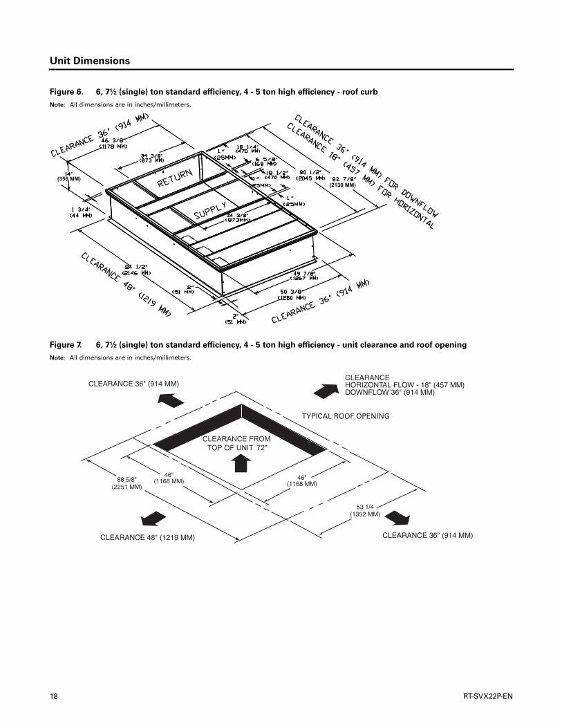
Figure 6. 6, 7½ (single) ton standard efficiency, 4 - 5 ton high efficiency - roof curb
Note: All dimensions are in inches/millimeters.
(2130 MM)(356 MM)
Figure 7. 6, 7½ (single) ton standard efficiency, 4 - 5 ton high efficiency - unit clearance and roof opening
Note: All dimensions are in inches/millimeters.
18 RT-SVX22P-EN

Unit Dimensions
Figure 8. 7½ ton (dual) - 10 ton standard efficiency, 6-8½ (microchannel) ton high efficiency, 6 ton dehumidification
Note: All dimensions are in inches/millimeters.
Figure 9. 7½ ton (dual) - 10 ton standard efficiency, 6-8½ (microchannel) ton high efficiency, 6 ton dehumidification
roof curb
Note: All dimensions are in inches/millimeters.
(2130 MM)(356 MM)
RT-SVX22P-EN 19

Unit Dimensions
Figure 10. 7½ ton (dual) - 10 ton standard efficiency, 6-8½ (microchannel) ton high efficiency,
6 ton dehumidification - unit clearance and roof opening)
Note: All dimensions are in inches/millimeters.
Figure 11. 10 ton high efficiency
Note: All dimensions are in inches/millimeters.
20 RT-SVX22P-EN

Unit Dimensions
Figure 12. 10 ton high efficiency - roof curb
Note: All dimensions are in inches/millimeters.
1 3/4”(44 MM)
2”(51 MM)
84 1/2”(2146 MM)
83 7/8”(2130 MM)
60 3/8”(1534 MM)
59 7/8”(1521 MM)
14”(356 MM)
2”(51 MM)
56 3/8”(1432 MM)
34 3/8”(873 MM)
34 3/8”(873 MM)
18 1/2”(470 MM)
18 1/2”(470 MM)
1”(25 MM)
1”(25 MM)
1”(25 MM)
6 5/8”(168 MM)
80 1/2”(2045 MM)
CLEARANCE 18” (457 MM) FOR HORIZONTAL
CLEARANCE 36” (914 MM) FOR DOWNFLOW
Figure 13. 10 ton high efficiency- unit clearance and roof opening
Note: All dimensions are in inches/millimeters.
99 11/16”(2532 MM)
63 3/16”(1605 MM)
RT-SVX22P-EN 21

Installation
Pre-Installation
Precautionary Measures
• Avoid breathing fiberglass dust.
• Use a NIOSH approved dust/mist respirator.
• Avoid contact with the skin or eyes.Wear long-sleeved,loose-fitting clothing, gloves, and eye protection.
• Wash clothes separately from other clothing: rinsewasher thoroughly.
• Operations such as sawing, blowing, tear-out, andspraying may generate fiber concentrations requiringadditional respiratory protection. Use the appropriateNIOSH approved respiration in these situations.
First Aid Measures
Eye Contact - Flush eyes with water to remove dust. Ifsymptoms persist, seek medical attention.
Skin Contact -Wash affected areas gently with soap andwarm water after handling.
Remove power to the unit and gain access to the electricheat elements by removing the horizontal supply cover.Visually inspect the heater elements for the following:
1. Elements that are no longer secured to the whiteceramic insulator.
2. Elements touching each other or touching metal.
3. Severely kinked, drooping, or broken elements.
If an element has detached from its ceramic insulator,carefully put it back into place.
Replace the heater elements if they present symptomsnoted in item Step 2 or Step 3 above.
Procedure
WARNING
Fiberglass Wool!
Product contains fiberglass wool. Disturbing theinsulation in this product during installation,maintenance or repair will expose you to airborneparticles of glass wool fibers and ceramic fibers knownto the state of California to cause cancer throughinhalation.You MUST wear all necessary PersonalProtective Equipment (PPE) including gloves, eyeprotection, mask, long sleeves and pants when workingwith products containing fiberglass wool. Exposition toglass wool fibers without all necessary PPE equipmentcould result in cancer, respiratory, skin or eye irritation,which could result in death or serious injury.
WARNING
Hazardous Voltage!
Disconnect all electric power, including remotedisconnects before servicing. Follow proper lockout/tagout procedures to ensure the power can not beinadvertently energized. Failure to disconnect powerbefore servicing could result in death or serious injury.
WARNING
Heavy Objects!
Ensure that all the lifting equipment used is properlyrated for the weight of the unit being lifted. Each of thecables (chains or slings), hooks, and shackles used tolift the unit must be capable of supporting the entireweight of the unit. Lifting cables (chains or slings) maynot be of the same length. Adjust as necessary for evenunit lift. Other lifting arrangements could causeequipment or property damage. Failure to followinstructions above or properly lift unit could result inunit dropping and possibly crushing operator/technician which could result in death or serious injury.
WARNING
Improper Unit Lift!
Test lift unit approximately 24 inches to verify propercenter of gravity lift point.To avoid dropping of unit,reposition lifting point if unit is not level. Failure toproperly lift unit could result in unit dropping andpossibly crushing operator/technician which couldresult in death or serious injury and possible equipmentor property-only damage.
Figure 14. Corner weights
22 RT-SVX22P-EN
Installation
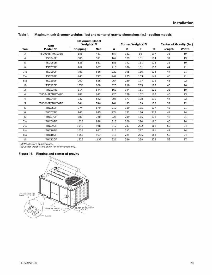
Table 1. Maximum unit & corner weights (lbs) and center of gravity dimensions (in.) - cooling models
Unit Model No.
Maximum Model Weights(a) Corner Weights(b) Center of Gravity (in.)
Ton Shipping Net A B C D Length Width
3 TSC036E/THC036E 555 481 157 122 95 107 31 19
4 TSC048E 586 511 167 129 101 114 31 19
5 TSC060E 636 561 183 142 111 125 31 19
6 TSC072F 762 667 218 186 131 132 44 21
7½ TSC090F 781 686 222 195 136 134 44 21
7½ TSC092F 940 797 249 235 163 149 46 21
8½ TSC102F 999 856 264 239 177 175 45 22
10 TSC120F 1058 960 320 218 233 189 40 24
3 THC037E 614 544 163 144 111 125 33 19
4 THC048E/THC047E 787 692 220 178 132 163 40 23
4 THC048F 737 642 208 177 128 130 44 22
5 THC060E/THC067E 841 746 241 193 139 173 39 22
5 THC060F 774 679 219 189 135 137 43 21
6 THC072E 943 845 274 172 186 213 41 24
6 THC072F 883 740 228 219 155 138 47 21
7½ THC092F 1026 928 315 209 224 180 40 24
7½ THC092F 1046 948 317 217 232 182 50 24
8½ THC102F 1035 937 316 212 227 181 49 24
8½ THC102F 1055 957 318 221 235 183 50 24
10 THC120F 1326 1132 326 326 258 222 53 27
(a) Weights are approximate.(b) Corner weights are given for information only.
Figure 15. Rigging and center of gravity
RT-SVX22P-EN 23

Installation
Foundation
Horizontal Units
If the unit is installed at ground level, elevate it above thesnow line. Provide concrete footings at each supportlocation with a “full perimeter” support structure or a slabfoundation for support. Refer to Table 1, p. 23 for the unit’soperating and point loading weights when constructing afooting foundation.
If anchoring is required, anchor the unit to the slab usinghold down bolts or isolators. Isolators should be installedto minimize the transmission of vibrations into thebuilding.
For rooftop applications, ensure the roof is strong enoughto support the combined unit and support structuralweight. Refer to Table 1, p. 23 for the unit operatingweights. If anchoring is required, anchor the unit to theroof with hold-down bolts or isolators.
Check with a roofing contractor for proper waterproofingprocedures.
Table 2. Factory installed options (fiops)/accessory net weights (lbs)(a),(b)
TSC036E-060ETHC036E/THC037E
THC047E-067ETHC048E/F-
060E/FTSC072F-102F
THC072E/F
THC092F-102F,
TSC120F THC120F
Net Weight Net Weight Net Weight Net Weight Net Weight
Accessory 3-5 Ton 4-5 Ton 6-8½ Ton7½, 8½-10
Ton 10 Ton
Barometric Relief 7 10 10 10 10
Belt Drive Option (3 phase only) 31 31 — — —
Coil Guards 12 20 20 20 30
Economizer 26 36 36 36 36
Electric Heaters 15 30 30 44 50
Hinged Doors 10 12 12 12 12
Low Leak Economizer 68 93 93 93 93
Manual Outside Air Damper 16 26 26 26 26
Motorized Outside Air Damper 20 30 30 30 30
Novar Control 8 8 8 8 8
Oversized Motor 5 8 8 — —
Powered Convenience Outlet 38 38 38 38 50
Powered Exhaust 40 40 80 80 80
Reheat Coil 12 14 15 — 30
Roof Curb 61 78 78 78 89
Smoke Detector, Supply 5 5 5 5 5
Smoke Detector, Return 7 7 7 7 7
Stainless Steel Heat Exchanger 4 6 6 6 6
Through the Base Electrical 8 13 13 13 13
Unit Mounted Circuit Breaker 5 5 5 5 5
Unit Mounted Disconnect 5 5 5 5 5
460V IDM(c) 29 29 - - -
(a) Weights for options not listed are <5 lbs.(b) Net weight should be added to unit weight when ordering factory-installed accessories.(c) Apply weight with all 460V 17 SEER Two-Stage Cooling units.
WARNING
Risk of Roof Collapsing!
Confirm with a structural engineer that the roofstructure is strong enough to support the combinedweight of the roof curb and the unit. Refer to Table 1,p. 23 for typical unit and curb weights. Failure to ensureproper structural roof support could cause the roof tocollapse, which could result in death or serious injuryand property damage.
24 RT-SVX22P-EN

Installation
Ductwork
Figure 16, p. 25 to Figure 18, p. 25 illustrate the supply andreturn air openings as viewed from the rear of the unit.
Figure 19, p. 25 to Figure 21, p. 26 illustrate the supply andreturn air openings in a downflow configuration.
Elbows with turning vanes or splitters are recommendedto minimize air noise due to turbulence and to reduce staticpressure.
When attaching the ductwork to the unit, provide a watertight flexible connector at the unit to prevent operatingsounds from transmitting through the ductwork.
All outdoor ductwork between the unit and the structureshould be weather proofed after installation is completed.
Figure 16. 3-5 ton standard efficiency units & 3 ton high
efficiency units - Horizontal supply & return
air openings
Figure 17. 4-6, 7½, 8½ (Microchannel) ton high
efficiency units and 6-10 ton standard
efficiency units - Horizontal supply & return
air openings
Figure 18. 10 ton high efficiency units - Horizontal
supply & return air openings
Supply
Return
3 7/8” 98 MM
9 3/8” 238 MM
19 1/4” 489 MM
16 3/4” 425 MM
4 3/4” 120 MM
32 1/4” 832 MM
27 5/8” 701 MM
Supply
Return
4 1/4” 108 MM
3/4-14 NPT DIA. HOLE CONDENSATE DRAIN
32 1/4” 832 MM
Figure 19. 3-5 ton standard efficiency units & 3 ton high
efficiency units - Downflow supply & return
air openings w/ through the base utilities
Figure 20. 4-6, 7½, 8½ (Microchannel) ton high
efficiency units and 6-10 ton standard
efficiency units - downflow supply & return
air openings w/ through the base utilities
RT-SVX22P-EN 25

Installation
Roof Curb
The roof curbs for these units consists of a“full perimeter”enclosure to support the unit just inside of the unit baserail.The 10 ton high efficiency units contains a supportbase alignment rail and will extend past the end of the roofcurb as shown in figures below and to the right.
Before installing any roof curb, verify;
• It is the correct curb for the unit,
• The includes the necessary gaskets and hardware,
• The purposed installation location provides therequired clearance for proper operation,
• Insure that the curb is level and square.The top surfaceof the curb must be true to assure an adequate curb-to-unit seal.
Verify that appropriate materials were used in theconstruction of roof and ductwork. Combustible materialsshould not be used in the construction of ductwork or roofcurb that is in close proximity to heater elements or anyhot surface. Any combustible material on the inside of theunit base should be removed and replaced withappropriate material.
Step-by-step curb assembly and installation instructionsship with each accessory roof curb kit. Follow theinstructions carefully to assure proper fit-up when the unitis set into place.
Note: To assure proper condensate flow duringoperation, the unit (and curb) must be level.
If the unit is elevated, a field constructed catwalk aroundthe unit is strongly recommended to provide easy accessfor unit maintenance and service.
Recommendations for installing the SupplyAir and ReturnAir ductwork joining the roof curb are included in the curbinstruction booklet. Curb ductwork must be fabricated andinstalled by the installing contractor before the unit is setinto place.
Note: For sound consideration, cut only the holes in theroof deck for the ductwork penetrations. Do not cutout the entire roof deck within the curb perimeter.
Figure 21. 10 ton high efficiency units - downflow supply
& return air openings w/ through the base
utilities
Table 3. Clearance required from duct to combustiblesurfaces
Model NumberClearance required from duct to combustible surfaces (inches)
T(S/H)C036-60E/F 0
THC037-67E 0
TSC072F 0
THC072E/F 1
TSC090F 1
TSC092F 0
THC092F 1
TSC102F 0
THC102F 1
TSC120F***A 0
TSC120F***B 1
THC120F 1
Supply Return
32 1/8” 816 MM
33” 838 MM
4” 102 MM
17 1/2” 444 MM
17 1/2” 444 MM
3 5/8” 92 MM 9 7/8”
251 MM
4 1/8” 104 MM
27 5/8” 701 MM
THROUGH THE BASE CONDENSATE
4 5/8” 119 MM
THROUGH THE BASE ELECTRICAL
51 13/16”
42 3/16” 1072 MM
5 7/8” 149 MM
6 3/8” 163 MM
2 3/4” 71 MM
WARNING
Combustible Materials!
Maintain proper clearance between the unit heatexchanger, vent surfaces and combustible materials.Refer to unit nameplate and installation instructions forproper clearances. Improper clearances could result incombustible materials catching on fire. Failure tomaintain proper clearances could result in death orserious injury or property damage.
Figure 22. View for base to roof curb alignment
THC120F on 50" x 84" roof curb
Base Alignment Bracket
26 RT-SVX22P-EN
Installation
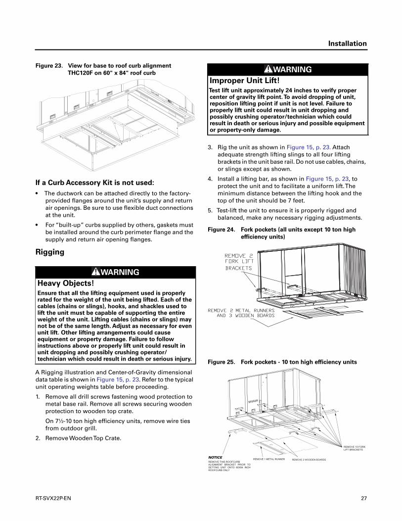
If a Curb Accessory Kit is not used:
• The ductwork can be attached directly to the factory-provided flanges around the unit’s supply and returnair openings. Be sure to use flexible duct connectionsat the unit.
• For “built-up” curbs supplied by others, gaskets mustbe installed around the curb perimeter flange and thesupply and return air opening flanges.
Rigging
A Rigging illustration and Center-of-Gravity dimensionaldata table is shown in Figure 15, p. 23. Refer to the typicalunit operating weights table before proceeding.
1. Remove all drill screws fastening wood protection tometal base rail. Remove all screws securing woodenprotection to wooden top crate.
On 7½-10 ton high efficiency units, remove wire tiesfrom outdoor grill.
2. Remove WoodenTop Crate.
3. Rig the unit as shown in Figure 15, p. 23. Attachadequate strength lifting slings to all four liftingbrackets in the unit base rail. Do not use cables, chains,or slings except as shown.
4. Install a lifting bar, as shown in Figure 15, p. 23, toprotect the unit and to facilitate a uniform lift.Theminimum distance between the lifting hook and thetop of the unit should be 7 feet.
5. Test-lift the unit to ensure it is properly rigged andbalanced, make any necessary rigging adjustments.
Figure 23. View for base to roof curb alignment
THC120F on 60" x 84" roof curb
WARNING
Heavy Objects!
Ensure that all the lifting equipment used is properlyrated for the weight of the unit being lifted. Each of thecables (chains or slings), hooks, and shackles used tolift the unit must be capable of supporting the entireweight of the unit. Lifting cables (chains or slings) maynot be of the same length. Adjust as necessary for evenunit lift. Other lifting arrangements could causeequipment or property damage. Failure to followinstructions above or properly lift unit could result inunit dropping and possibly crushing operator/technician which could result in death or serious injury.
WARNING
Improper Unit Lift!
Test lift unit approximately 24 inches to verify propercenter of gravity lift point.To avoid dropping of unit,reposition lifting point if unit is not level. Failure toproperly lift unit could result in unit dropping andpossibly crushing operator/technician which couldresult in death or serious injury and possible equipmentor property-only damage.
Figure 24. Fork pockets (all units except 10 ton high
efficiency units)
Figure 25. Fork pockets - 10 ton high efficiency units
NOTICE
RT-SVX22P-EN 27

Installation
6. Lift the unit enough to allow the removal of base forkpocket protection components as shown in thefollowing figures.
7. When 10 ton high efficiency units are installed onsmaller existing roof curb (50"x 84") for replacementapplications, do not remove alignment bracket.Thisbracket helps assure proper alignment of ductopenings.
8. Downflow units; align the base rail of the unit with thecurb rail while lowering the unit onto the curb. Makesure that the gasket on the curb is not damaged whilepositioning the unit.
General Unit Requirements
The checklist listed below is a summary of the stepsrequired to successfully install a commercial unit.Thischecklist is intended to acquaint the installing personnelwith what is required in the installation process. It does notreplace the detailed instructions called out in theapplicable sections of this manual.
• Check the unit for shipping damage and materialshortage; file a freight claim and notify appropriatesales representative.
• Verify correct model, options and voltage from unitnameplate.
• Verify that the installation location of the unit willprovide the required clearance for proper operation.
• Assemble and install the roof curb (if applicable). Referto the latest edition of the curb installers guide thatships with each curb kit.
• Fabricate and install ductwork; secure ductwork tocurb.
• Install pitch pocket for power supply through buildingroof. (If applicable)
• Rigging the unit.
• Set the unit onto the curb; check for levelness.
• Ensure unit-to-curb seal is tight and without buckles orcracks.
• Install and connect a condensate drain line to theevaporator drain connection.
Factory Installed Economizer
• Ensure the economizer has been pulled out into theoperating position. Refer to the economizer installersguide for proper position and setup.
• Install all access panels.
Temperature Limit Switch Usage forElectric Heat Units
Units are factory shipped in the downflow dischargeconfiguration but can be field converted to a horizontaldischarge configuration. Some, but not all units require a
differentTCO-A limit switch, which is wire tied near theterminal block in the heater compartment if horizontaldischarge configuration is used.
Horizontal Discharge Conversion
(3 to 5Ton Units)
Note: 3 to 5 ton units supply cover to supply opening andreturn cover to return opening.
Supplies Needed by Installer for Conversion: 3 oz. tube ofHighTemperature RTV sealant. (500°F / 260°C: Similar toDow Corning 736)
Note: Failure to use recommended sealant could result inunit performance loss.
If a unit is to be converted to a Horizontal discharge, thefollowing conversion must be performed:
1. Remove RETURN and SUPPLY duct covers.
2. Locate supply cover. Apply ¼ in. (6mm.) continuousbead of 500°F RTV sealant to the flange as shown.
3. Position duct cover as shown, rotate 90 degrees toallow entrance into supply opening.
4. Slide duct covers into duct openings until inward edgeof duct cover engages with the 2 retaining clips on theduct flanges. Secure the outward edge of each ductcover with 2 screws.
5. Slide RETURN DUCT COVER (insulation side up) intosupply opening until inward edge of duct coverengages with the 2 retaining clips on the duct flange.Secure outward edge of the duct cover with twoscrews.
Note: Certain unit/electric heater combinations require alimit switch change out for horizontal airflowapplications. Refer to the following instructions todetermine if this process is required for the unitundergoing installation.
Horizontal Discharge Conversion
(6 to 10Ton Units)
Note: 6 to 10 ton units the supply cover to return opening& return cover to supply opening.
Supplies Needed by Installer for Conversion: 3 oz. tube ofhighTemperature RTV sealant. (500°F / 260°C: Similar toDow Corning 736)
Figure 26. Supply duct cover
RTV Sealant
28 RT-SVX22P-EN
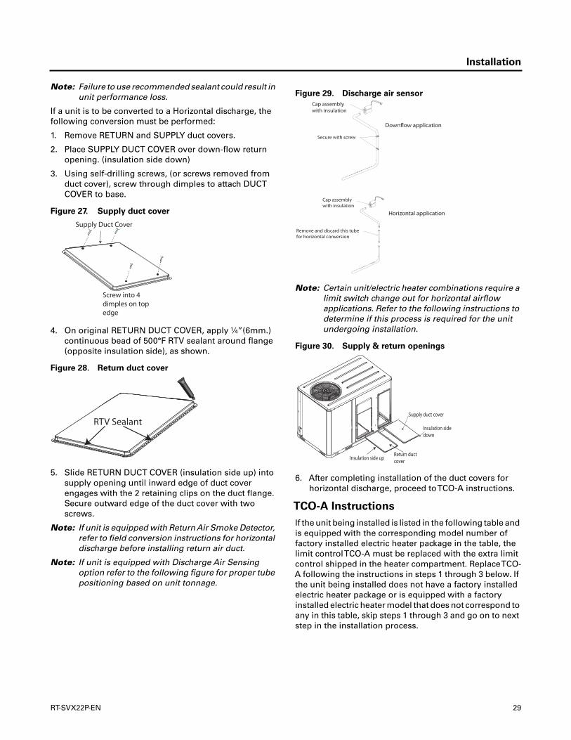
Installation
Note: Failure to use recommended sealant could result inunit performance loss.
If a unit is to be converted to a Horizontal discharge, thefollowing conversion must be performed:
1. Remove RETURN and SUPPLY duct covers.
2. Place SUPPLY DUCT COVER over down-flow returnopening. (insulation side down)
3. Using self-drilling screws, (or screws removed fromduct cover), screw through dimples to attach DUCTCOVER to base.
4. On original RETURN DUCT COVER, apply ¼”(6mm.)continuous bead of 500°F RTV sealant around flange(opposite insulation side), as shown.
5. Slide RETURN DUCT COVER (insulation side up) intosupply opening until inward edge of duct coverengages with the 2 retaining clips on the duct flange.Secure outward edge of the duct cover with twoscrews.
Note: If unit is equipped with Return Air Smoke Detector,refer to field conversion instructions for horizontaldischarge before installing return air duct.
Note: If unit is equipped with Discharge Air Sensingoption refer to the following figure for proper tubepositioning based on unit tonnage.
Note: Certain unit/electric heater combinations require alimit switch change out for horizontal airflowapplications. Refer to the following instructions todetermine if this process is required for the unitundergoing installation.
6. After completing installation of the duct covers forhorizontal discharge, proceed toTCO-A instructions.
TCO-A Instructions
If the unit being installed is listed in the following table andis equipped with the corresponding model number offactory installed electric heater package in the table, thelimit controlTCO-A must be replaced with the extra limitcontrol shipped in the heater compartment. ReplaceTCO-A following the instructions in steps 1 through 3 below. Ifthe unit being installed does not have a factory installedelectric heater package or is equipped with a factoryinstalled electric heater model that does not correspond toany in this table, skip steps 1 through 3 and go on to nextstep in the installation process.
Figure 27. Supply duct cover
Figure 28. Return duct cover
Supply Duct Cover
Screw into 4dimples on top edge
RTV Sealant
Figure 29. Discharge air sensor
Figure 30. Supply & return openings
Downflow application
Horizontal application
Cap assemblywith insulation
Remove and discard this tube for horizontal conversion
Cap assembly with insulation
Secure with screw
Insulation side down
Supply duct cover
Insulation side upReturn duct cover
RT-SVX22P-EN 29
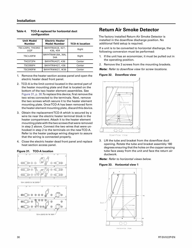
Installation
1. Remove the heater section access panel and open theelectric heater dead front panel.
2. TCO-A is the limit control located in the central part ofthe heater mounting plate and that is located on thebottom of the two heater element assemblies. SeeFigure 31, p. 30.To replace this device, first remove thetwo wires connected to the terminals. Next, removethe two screws which secure it to the heater elementmounting plate. OnceTCO-A has been removed formthe heater element mounting plate, discard this device.
3. Obtain the replacementTCO-A which is secured by awire tie near the electric heater terminal block in theheater compartment. Attach it to the heater elementmounting plate with the two screws that were removedin step 2 above. Connect the two wires that were un-hooked in step 2 to the terminals on the newTCO-A.Refer to the heater package wiring diagram to assurethat the wiring is connected properly.
4. Close the electric heater dead front panel and replaceheat section access panel.
Return Air Smoke Detector
The factory installed Return Air Smoke Detector isinstalled in the downflow discharge position. Noadditional field setup is required.
If a unit is to be converted to horizontal discharge, thefollowing conversion must be performed:
1. If the unit has an economizer, it must be pulled out inthe operating position.
2. Remove the 3 screws from the mounting brackets.
Note: Refer to downflow view for screw locations.
3. Lift the tube and bracket from the downflow ductopening. Rotate the tube and bracket assembly 180degrees ensuring that the holes on the copper sensingtube face away from the unit and face the return airductwork.
Note: Refer to horizontal views below.
Table 4. TCO-A replaced for horizontal ductconfiguration
Unit Model Number
Electric Heater Model Number TCO-A location
TSC120F4, THC092-102F
BAYHTRA418, 427, 436, 454 Right
TSC120FW BAYHTRAW18A, 36A, 54A Right
THC072F4 BAYHTRU427, 436 Center
TSC090F4 BAYHTRW427, 436 Center
TSC090FW BAYHTRWW27, W36 Center
Figure 31. TCO-A location
Figure 32. Downflow view
Figure 33. Horizontal view 1
30 RT-SVX22P-EN

Installation
Note: Check to insure that the flexible tubing lies flat onthe base pan surface.
4. Slide the top bracket down the copper sensing tube.ForTSC036E-060E, andTHC036-037E units insert thetab on the left side into the slot on the indoor coil blockoff and secure the right side of the bracket with one ofthe 3 screws removed in step 2. Refer to Figure 33,p. 30. ForTHC047E-072E,THC048F-120F, andTSC072F-120F units secure the tab on left side to the indoor coilblock off with one of the screws removed in step 2 andsecure the right side of the bracket with one of thescrews removed from the access panel. Refer toFigure 34, p. 31.
5. Using the remaining 2 screws removed in step 2,secure the bottom bracket. Refer to Figure 33, p. 30.
Note: Larger diameter holes on bottom bracket line upwith the dimples on the rear panel.The smallerdiameter holes line up with the screw holes in therear panel.
Main Electrical Power
Requirements
• Verify that the power supply complies with the unitnameplate specifications.
• Inspect all control panel components; tighten anyloose connections.
• Connect properly sized and protected power supplywiring to a field-supplied/installed disconnect switchand to the main power terminal block (HTB1) in the unitcontrol panel.
• Install proper grounding wires to an earth ground.
Electric Heat Requirements
• Verify that the power supply complies with the electricheater specifications on the unit and heater nameplate.
• Inspect the heater junction box and control panel;tighten any loose connections.
• Check electric heat circuits for continuity.
Low Voltage Wiring(AC & DC) Requirements
• Install the zone thermostat, with or without switchingsubbase.
• Connect properly sized control wiring to the propertermination points between the zone thermostat andthe unit control panel.
Figure 34. Horizontal view 2
4
2
WARNING
Hazardous Voltage w/Capacitors!
Disconnect all electric power, including remotedisconnects and discharge all motor start/runcapacitors before servicing. Follow proper lockout/tagout procedures to ensure the power cannot beinadvertently energized. Verify with an appropriatevoltmeter that all capacitors have discharged. Failure todisconnect power and discharge capacitors beforeservicing could result in death or serious injury.
For additional information regarding the safe dischargeof capacitors, see PROD-SVB06A-EN
WARNING
Proper Field Wiring and GroundingRequired!
All field wiring MUST be performed by qualifiedpersonnel. Improperly installed and grounded fieldwiring poses FIRE and ELECTROCUTION hazards.Toavoid these hazards, you MUST follow requirements forfield wiring installation and grounding as described inNEC and your local/state electrical codes. Failure tofollow code could result in death or serious injury.
RT-SVX22P-EN 31
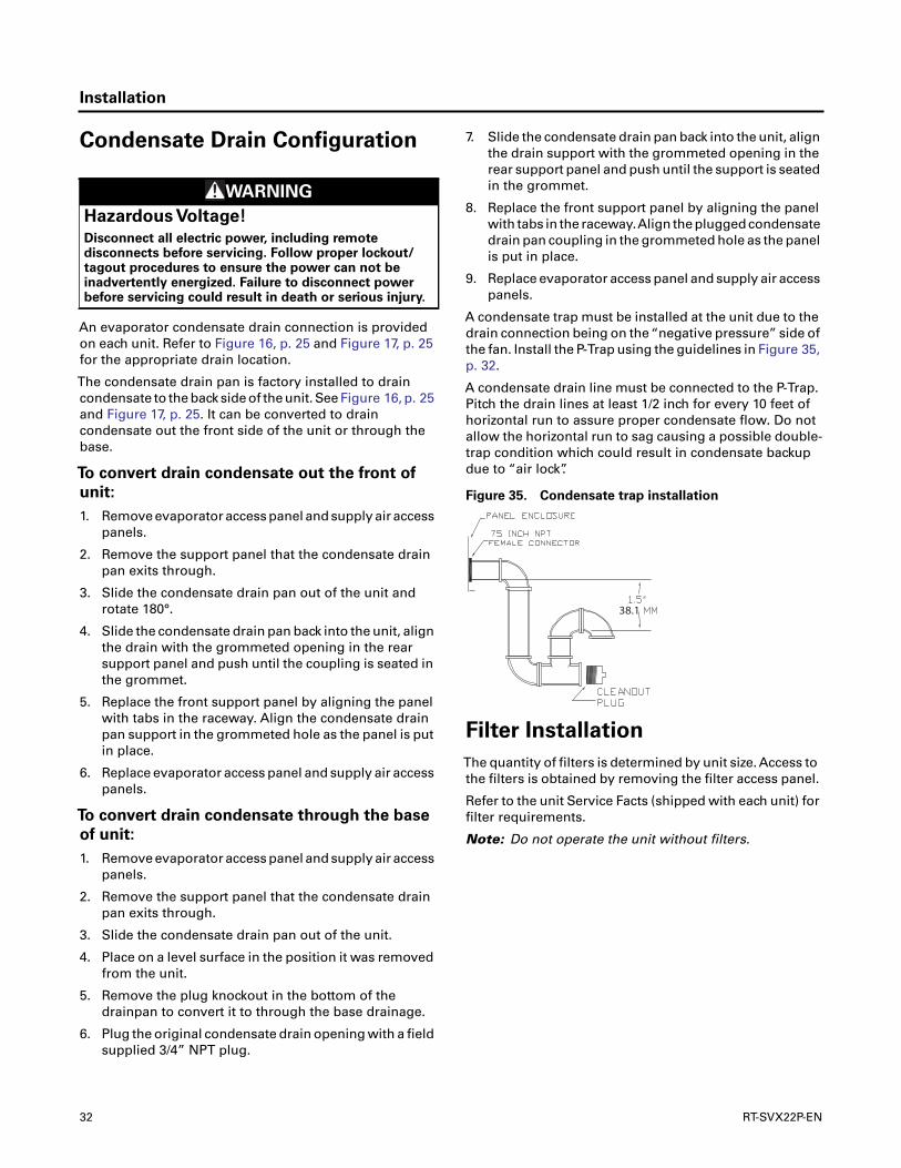
Installation
Condensate Drain Configuration
An evaporator condensate drain connection is providedon each unit. Refer to Figure 16, p. 25 and Figure 17, p. 25for the appropriate drain location.
The condensate drain pan is factory installed to draincondensate to the back side of the unit. See Figure 16, p. 25and Figure 17, p. 25. It can be converted to draincondensate out the front side of the unit or through thebase.
To convert drain condensate out the front of
unit:
1. Remove evaporator access panel and supply air accesspanels.
2. Remove the support panel that the condensate drainpan exits through.
3. Slide the condensate drain pan out of the unit androtate 180°.
4. Slide the condensate drain pan back into the unit, alignthe drain with the grommeted opening in the rearsupport panel and push until the coupling is seated inthe grommet.
5. Replace the front support panel by aligning the panelwith tabs in the raceway. Align the condensate drainpan support in the grommeted hole as the panel is putin place.
6. Replace evaporator access panel and supply air accesspanels.
To convert drain condensate through the base
of unit:
1. Remove evaporator access panel and supply air accesspanels.
2. Remove the support panel that the condensate drainpan exits through.
3. Slide the condensate drain pan out of the unit.
4. Place on a level surface in the position it was removedfrom the unit.
5. Remove the plug knockout in the bottom of thedrainpan to convert it to through the base drainage.
6. Plug the original condensate drain opening with a fieldsupplied 3/4” NPT plug.
7. Slide the condensate drain pan back into the unit, alignthe drain support with the grommeted opening in therear support panel and push until the support is seatedin the grommet.
8. Replace the front support panel by aligning the panelwith tabs in the raceway.Align the plugged condensatedrain pan coupling in the grommeted hole as the panelis put in place.
9. Replace evaporator access panel and supply air accesspanels.
A condensate trap must be installed at the unit due to thedrain connection being on the “negative pressure” side ofthe fan. Install the P-Trap using the guidelines in Figure 35,p. 32.
A condensate drain line must be connected to the P-Trap.Pitch the drain lines at least 1/2 inch for every 10 feet ofhorizontal run to assure proper condensate flow. Do notallow the horizontal run to sag causing a possible double-trap condition which could result in condensate backupdue to “air lock”.
Filter Installation
The quantity of filters is determined by unit size. Access tothe filters is obtained by removing the filter access panel.
Refer to the unit Service Facts (shipped with each unit) forfilter requirements.
Note: Do not operate the unit without filters.
WARNING
Hazardous Voltage!
Disconnect all electric power, including remotedisconnects before servicing. Follow proper lockout/tagout procedures to ensure the power can not beinadvertently energized. Failure to disconnect powerbefore servicing could result in death or serious injury.
Figure 35. Condensate trap installation
38.1
32 RT-SVX22P-EN
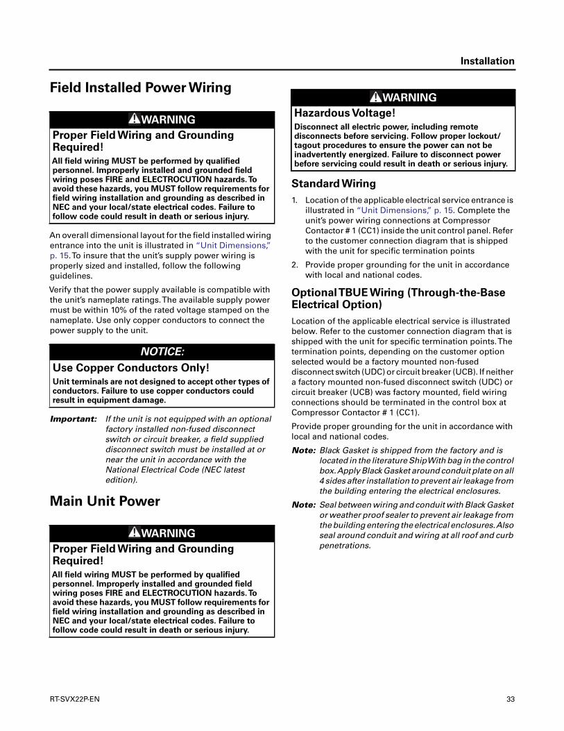
Installation
Field Installed Power Wiring
An overall dimensional layout for the field installed wiringentrance into the unit is illustrated in “Unit Dimensions,”p. 15.To insure that the unit’s supply power wiring isproperly sized and installed, follow the followingguidelines.
Verify that the power supply available is compatible withthe unit’s nameplate ratings.The available supply powermust be within 10% of the rated voltage stamped on thenameplate. Use only copper conductors to connect thepower supply to the unit.
Important: If the unit is not equipped with an optionalfactory installed non-fused disconnectswitch or circuit breaker, a field supplieddisconnect switch must be installed at ornear the unit in accordance with theNational Electrical Code (NEC latestedition).
Main Unit Power
Standard Wiring
1. Location of the applicable electrical service entrance isillustrated in “Unit Dimensions,” p. 15. Complete theunit’s power wiring connections at CompressorContactor # 1 (CC1) inside the unit control panel. Referto the customer connection diagram that is shippedwith the unit for specific termination points
2. Provide proper grounding for the unit in accordancewith local and national codes.
OptionalTBUE Wiring (Through-the-BaseElectrical Option)
Location of the applicable electrical service is illustratedbelow. Refer to the customer connection diagram that isshipped with the unit for specific termination points.Thetermination points, depending on the customer optionselected would be a factory mounted non-fuseddisconnect switch (UDC) or circuit breaker (UCB). If neithera factory mounted non-fused disconnect switch (UDC) orcircuit breaker (UCB) was factory mounted, field wiringconnections should be terminated in the control box atCompressor Contactor # 1 (CC1).
Provide proper grounding for the unit in accordance withlocal and national codes.
Note: Black Gasket is shipped from the factory and islocated in the literature ShipWith bag in the controlbox.Apply Black Gasket around conduit plate on all4 sides after installation to prevent air leakage fromthe building entering the electrical enclosures.
Note: Seal between wiring and conduit with Black Gasketor weather proof sealer to prevent air leakage fromthe building entering the electrical enclosures.Alsoseal around conduit and wiring at all roof and curbpenetrations.
WARNING
Proper Field Wiring and GroundingRequired!
All field wiring MUST be performed by qualifiedpersonnel. Improperly installed and grounded fieldwiring poses FIRE and ELECTROCUTION hazards.Toavoid these hazards, you MUST follow requirements forfield wiring installation and grounding as described inNEC and your local/state electrical codes. Failure tofollow code could result in death or serious injury.
NOTICE:
Use Copper Conductors Only!
Unit terminals are not designed to accept other types ofconductors. Failure to use copper conductors couldresult in equipment damage.
WARNING
Proper Field Wiring and GroundingRequired!
All field wiring MUST be performed by qualifiedpersonnel. Improperly installed and grounded fieldwiring poses FIRE and ELECTROCUTION hazards.Toavoid these hazards, you MUST follow requirements forfield wiring installation and grounding as described inNEC and your local/state electrical codes. Failure tofollow code could result in death or serious injury.
WARNING
Hazardous Voltage!
Disconnect all electric power, including remotedisconnects before servicing. Follow proper lockout/tagout procedures to ensure the power can not beinadvertently energized. Failure to disconnect powerbefore servicing could result in death or serious injury.
RT-SVX22P-EN 33
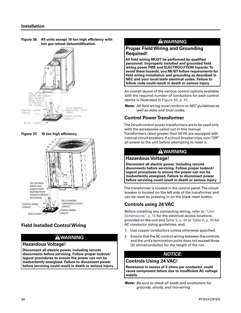
Installation
Field Installed Control Wiring
An overall layout of the various control options availablewith the required number of conductors for each controldevice is illustrated in Figure 50, p. 41.
Note: All field wiring must conform to NEC guidelines aswell as state and local codes.
Control PowerTransformer
The 24 volt control power transformers are to be used onlywith the accessories called out in this manual.Transformers rated greater than 50 VA are equipped withinternal circuit breakers. If a circuit breaker trips, turn“Off”all power to the unit before attempting to reset it.
The transformer is located in the control panel.The circuitbreaker is located on the left side of the transformer andcan be reset by pressing in on the black reset button.
Controls using 24 VAC
Before installing any connecting wiring, refer to “UnitDimensions,” p. 15 for the electrical access locationsprovided on the unit and Table 5, p. 35 or Table 6, p. 35 forAC conductor sizing guidelines, and;
1. Use copper conductors unless otherwise specified.
2. Ensure that theAC control wiring between the controlsand the unit’s termination point does not exceed three(3) ohms/conductor for the length of the run.
Note: Be sure to check all loads and conductors forgrounds, shorts, and mis-wiring.
Figure 36. All units except 10 ton high efficiency with
hot gas reheat dehumidification.
Figure 37. 10 ton high efficiency
WARNING
Hazardous Voltage!
Disconnect all electric power, including remotedisconnects before servicing. Follow proper lockout/tagout procedures to ensure the power can not beinadvertently energized. Failure to disconnect powerbefore servicing could result in death or serious injury.
CONTROL WIRING CONDUIT
BLACK GASKETCONTROL WIRING CONDUIT
FIELD POWEREDCONVENIENCE OUTLETCONDUIT
SEAL BETWEENWIRING AND CONDUIT WITH WEATHER PROOF SEALER TO PREVENTAIR LEAKAGE
WARNING
Proper Field Wiring and GroundingRequired!
All field wiring MUST be performed by qualifiedpersonnel. Improperly installed and grounded fieldwiring poses FIRE and ELECTROCUTION hazards.Toavoid these hazards, you MUST follow requirements forfield wiring installation and grounding as described inNEC and your local/state electrical codes. Failure tofollow code could result in death or serious injury.
WARNING
Hazardous Voltage!
Disconnect all electric power, including remotedisconnects before servicing. Follow proper lockout/tagout procedures to ensure the power can not beinadvertently energized. Failure to disconnect powerbefore servicing could result in death or serious injury.
NOTICE:
Controls Using 24 VAC!
Resistance in excess of 3 ohms per conductor couldcause component failure due to insufficient AC voltagesupply.
34 RT-SVX22P-EN

Installation
3. Do not run the AC low voltage wiring in the sameconduit with the high voltage power wiring.
4. Route low voltage wiring per illustrations on pageFigure 43, p. 37.
Controls using DC AnalogInput/Outputs (Standard Low VoltageMulti conductor Wire)
Before installing any connecting wiring between the unitand components utilizing a DC analog input/output signal,refer to “Unit Dimensions,” p. 15 for the electrical accesslocations provided on the unit.
• Table 7, p. 35 lists the conductor sizing guidelines thatmust be followed when interconnecting the DC binaryoutput devices and the system components utilizing aDC analog input/output signal to the unit.
Note: Resistance in excess of 2.5 ohms per conductor cancause deviations in the accuracy of the controls.
Note: Ensure that the wiring between controls and theunit’s termination point does not exceed two and ahalf (2.5) ohms/conductor for the length of the run.
• Do not run the electrical wires transporting DC signalsin or around conduit housing high voltage wires.
• Route low voltage wiring per illustrations on page 37.
Note: If digit 9 in the unit model number equals “E”(Electro Mechanical Control), accessory relay
BAY24X042 is required if the thermostat does notenergize the fan circuit in the heating mode.
DC Conductors
Table 5. Electromechanical thermostat 24V ACconductors with ReliaTel™ units
Distance from Unit to Control Recommended Wire Size
000 - 460 feet 18 gauge
000 - 140 m .75 mm2
461 - 732 feet 16 gauge
141 - 223 m 1.3 mm2
733 - 1000 feet 14 gauge
224 - 305 m 2.0 mm2
Table 6. Electromechanical thermostat 24V ACconductors with Electromechanical unit
Distance from Unit to Control Recommended Wire Size
0 - 30 feet 22 gauge
0 - 9.1 m .33 m2
31 - 50 feet 20 gauge
9.5 - 15.2 m .50m2
51 - 75 feet 18 gauge
15.5 - 22.9 m .75 m2
76 - 125 feet 16 gauge
23.1 - 38.1 m 1.3 m2
126 - 200 feet 14 gauge
38.4 - 60.9 m 2.0 m2
Table 7. Zone sensor module wiring
Distance from Unit to Control Recommended Wire Size
0 - 150 feet 22 gauge
0 - 45.7 m .33 mm2
151 - 240 feet 20 gauge
46 - 73.1 m .50 mm2
241 -385 feet 18 gauge
73.5 - 117.3 m .75 mm2
386 - 610 feet 16 gauge
117.7 - 185.9 m 1.3 mm2
611 - 970 feet 14 gauge
186.2 - 295.7 m 2.0 mm2
Figure 38. ReliaTel™ conventional thermostat field
wiring diagrams
Figure 39. Typical field wiring diagrams for electro
mechanical thermostat
RTRM
100 P (Red)
173 C (Brn)
101MM (Blu)
175 D (Blk)
174 B (Brn)
176 D (Yellow)
184 A (Yellow)
RT-SVX22P-EN 35

Installation
Figure 40. ReliaTel options module
Figure 41. ReliaTel™ relative humidity sensor
(dehumidification option)
Figure 42. ReliaTel humidistat (dehumidification
option)
36 RT-SVX22P-EN
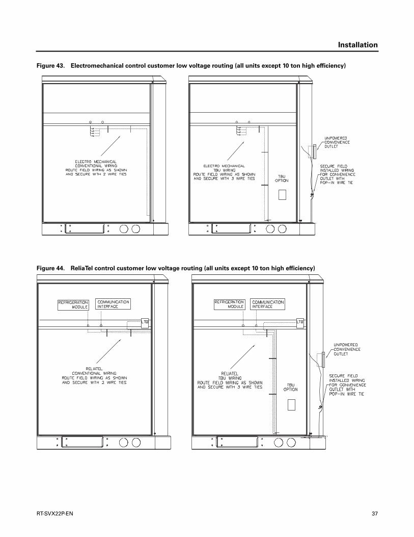
Installation
Figure 43. Electromechanical control customer low voltage routing (all units except 10 ton high efficiency)
Figure 44. ReliaTel control customer low voltage routing (all units except 10 ton high efficiency)
RT-SVX22P-EN 37
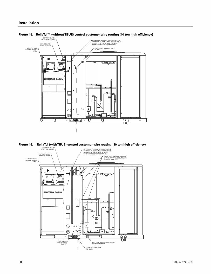
Installation
Figure 45. ReliaTel™ (withoutTBUE) control customer wire routing (10 ton high efficiency)
Figure 46. ReliaTel (withTBUE) control customer wire routing (10 ton high efficiency)
38 RT-SVX22P-EN

Installation
Figure 47. Electromechanical (withoutTBUE) control customer wire routing (10 ton high efficiency)
Figure 48. Electromechanical (withTBUE) control customer wire routing (10 ton high efficiency)
RT-SVX22P-EN 39

Installation
SpaceTemperature Averaging
(ReliaTel™ only)
Space temperature averaging is accomplished by wiring anumber of remote sensors in a series/parallel circuit.
Using the BAYSENS016* or BAYSENS077*, at least foursensors are required to accomplish space temperatureaveraging.
• Example #1 illustrates two series circuits with twosensors in each circuit wired in parallel.The square ofany number of remote sensors is required.
• Example #2 illustrates three sensors squared in aseries/parallel circuit. Using BAYSENS077*, twosensors are required to accomplish space temperatureaveraging.
Example #3 illustrates the circuit required for this sensor.Table 8, p. 42 lists the temperature versus resistancecoefficient for all sensors.
Note: Wiring pin numbers are for reference only.Thereare multiple smoke detector systems that couldhave differently numbered pins. For correct wiring
details, please refer to the specific smoke detectorliterature that accompanied this unit.
Figure 49. Examples
40 RT-SVX22P-EN

Installation
Figure 50. Typical field wiring diagrams for optional controls (ReliaTel™ only)
BAYSENS075*BAYSENS075*
BAYSENS119*
BAYSENS110*BAYSENS108*BAYSENS106*
BAYSENS073* BAYSENS074*BAYSENS075*ASYSTAT669AOPTIONAL REMOTE SENSOR
RT-SVX22P-EN 41
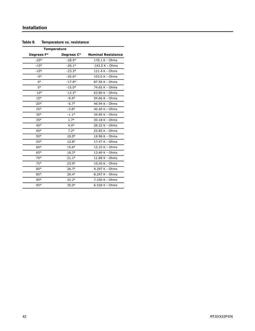
Installation
Table 8. Temperature vs. resistance
Temperature
Degrees F° Degrees C° Nominal Resistance
-20° -28.9° 170.1 K - Ohms
-15° -26.1° 143.5 K - Ohms
-10° -23.3° 121.4 K - Ohms
-5° -20.6° 103.0 K - Ohms
0° -17.8° 87.56 K - Ohms
5° -15.0° 74.65 K - Ohms
10° -12.2° 63.80 K - Ohms
15° -9.4° 54.66 K - Ohms
20° -6.7° 46.94 K - Ohms
25° -3.8° 40.40 K - Ohms
30° -1.1° 34.85 K - Ohms
35° 1.7° 30.18 K - Ohms
40° 4.4° 26.22 K - Ohms
45° 7.2° 22.85 K - Ohms
50° 10.0° 19.96 K - Ohms
55° 12.8° 17.47 K - Ohms
60° 15.6° 15.33 K - Ohms
65° 18.3° 13.49 K - Ohms
70° 21.1° 11.89 K - Ohms
75° 23.9° 10.50 K - Ohms
80° 26.7° 9.297 K - Ohms
85° 29.4° 8.247 K - Ohms
90° 32.2° 7.330 K - Ohms
95° 35.0° 6.528 K - Ohms
42 RT-SVX22P-EN

Pre-Start
Use the checklist provided below in conjunction with the“General Unit Requirements” checklist to ensure that theunit is properly installed and ready for operation.
• Check all electrical connections for tightness and“point of termination” accuracy.
• Verify that the condenser airflow will be unobstructed.
• Verify that the condenser fan and indoor blower turnfreely without rubbing and are properly tightened onthe shafts.
• Check the supply fan belts for proper tension and thefan bearings for sufficient lubrication. If the beltsrequire adjustment, or if the bearings need lubricating,refer to the maintenance section of this manual forinstructions.
• Verify that a condensate trap is installed and the pipingis properly sized and pitched.
• Verify that the correct size and number of filters are inplace.
• Inspect the interior of the unit for tools and debris andinstall all panels in preparation for starting the unit.
Voltage Imbalance
Three phase electrical power to the unit must meetstringent requirements for the unit to operate properly.
Measure each leg (phase-to-phase) of the power supply.Each reading must fall within the utilization range stampedon the unit nameplate. If any of the readings do not fallwithin the proper tolerances, notify the power company tocorrect this situation before operating the unit.
Excessive three phase voltage imbalance between phaseswill cause motors to overheat and eventually fail.Themaximum allowable voltage imbalance is 2%. Measureand record the voltage between phases 1, 2, and 3 andcalculate the amount of imbalance as follows:
V1, V2, V3 = Line Voltage Readings
VD = Line Voltage reading that deviates the farthest fromthe average voltage.
Example: If the voltage readings of the supply powermeasured 221, 230, and 227, the average volts would be:
VD (reading farthest from average) = 221
The percentage of Imbalance equals:
The 2.2% imbalance in this example exceeds themaximum allowable imbalance of 2.0%.This muchimbalance between phases can equal as much as a 20%current imbalance with a resulting increase in motorwinding temperatures that will decrease motor life. If thevoltage imbalance is over 2%, notify the proper agenciesto correct the voltage problem before operating thisequipment.
Electrical Phasing (Three Phase
Motors)
The compressor motor(s) and the supply fan motor areinternally connected for the proper rotation when theincoming power supply is phased as A, B, C.
Proper electrical supply phasing can be quicklydetermined and corrected before starting the unit by usingan instrument such as an Associated Research Model 45Phase Sequence Indicator and following the steps below:
WARNING
Hazardous Voltage w/Capacitors!
Disconnect all electric power, including remotedisconnects and discharge all motor start/runcapacitors before servicing. Follow proper lockout/tagout procedures to ensure the power cannot beinadvertently energized. Verify with an appropriatevoltmeter that all capacitors have discharged. Failure todisconnect power and discharge capacitors beforeservicing could result in death or serious injury.
For additional information regarding the safe dischargeof capacitors, see PROD-SVB06A-EN
% Voltage Imbalance= 100 x AV - VD
where;AV
AV (Average Voltage)= Volt 1 + Volt 2 + Volt 3
3
221 + 230 + 227 = 226 Avg.
3
100 x 226 - 221 = 2.2%
226
WARNING
Hazardous Voltage w/Capacitors!
Disconnect all electric power, including remotedisconnects and discharge all motor start/runcapacitors before servicing. Follow proper lockout/tagout procedures to ensure the power cannot beinadvertently energized. Verify with an appropriatevoltmeter that all capacitors have discharged. Failure todisconnect power and discharge capacitors beforeservicing could result in death or serious injury.
For additional information regarding the safe dischargeof capacitors, see PROD-SVB06A-EN
RT-SVX22P-EN 43

Pre-Start
• Turn the field supplied disconnect switch that providespower to the main power terminal block or to the“Line” side of the optional factory mounted disconnectswitch to the “Off” position.
• Connect the phase sequence indicator leads to theterminal block or to the “Line” side of the optionalfactory mounted disconnect switch as follows;
• Black (phase A) to L1
• Red (phase B) to L2
• Yellow (phase C) to L3
• Close the field supplied main power disconnect switchor circuit protector switch that provides the supplypower to the unit.
To prevent injury or death from electrocution, it is theresponsibility of the technician to recognize this hazardand use extreme care when performing serviceprocedures with the electrical power energized.
• Observe theABC and CBA phase indicator lights on theface of the sequencer.TheABC indicator light will glowif the phase is ABC. If the CBA indicator light glows,open the disconnect switch or circuit protection switchand reverse any two power wires.
• Restore the main electrical power and recheck thephasing. If the phasing is correct, open the disconnectswitch or circuit protection switch and remove thephase sequence indicator.
Compressor Crankcase Heaters (Optional)
Each compressor can be equipped with a crankcase heater(On some units the crankcase heater comes standard).Theproper operation of the crankcase heater is important tomaintain an elevated compressor oil temperature duringthe “Off” cycle to reduce oil foaming during compressorstarts.
Oil foaming occurs when refrigerant condenses in thecompressor and mixes with the oil. In lower ambientconditions, refrigerant migration to the compressor couldincrease.
When the compressor starts, the sudden reduction incrankcase pressure causes the liquid refrigerant to boilrapidly causing the oil to foam.This condition coulddamage compressor bearings due to reduced lubricationand could cause compressor mechanical failures.
Before starting the unit in the “Cooling” mode, set thesystem switch to the “Off” position and turn the mainpower disconnect to the “On” position and allow thecrankcase heater to operate a minimum of 8 hours.
Before closing the main power disconnect switch, insurethat the “System” selection switch is in the “Off” positionand the “Fan” selection switch is in the “Auto” position.
Close the main power disconnect switch and the unitmounted disconnect switch, if applicable.
Note: Upon closing main power disconnect and the unitmounted disconnect switch or circuit breaker, thephase monitor will verify proper phasing. If LED onface of the monitor is red, correct supply powerfault.
To prevent injury or death from electrocution, it is theresponsibility of the technician to recognize this hazardand use extreme care when performing serviceprocedures with the electrical power energized.
ReliaTel™ Controls
Upon power initialization, the RTRM performs self-diagnostic checks to insure that all internal controls arefunctional. It also checks the configuration parametersagainst the components connected to the system.TheLiteport LED located on the RTRM module is turned “On”within one second of power-up if internal operation isokay.
Use one of the following“Test” procedure to bypass sometime delays and to start the unit at the control panel. Eachstep of unit operation can be activated individually bytemporarily shorting across the“Test” terminals for two tothree seconds.The Liteport LED located on the RTRMmodule will blink when the test mode has been initiated.The unit can be left in any “Test” step for up to one hourbefore it will automatically terminate, or it can beterminated by opening the main power disconnect switch.Once the test mode has been terminated, the Liteport LEDwill glow continuously and the unit will revert to the“System” control.
WARNING
Live Electrical Components!
During installation, testing, servicing andtroubleshooting of this product, it may be necessary towork with live electrical components. Have a qualifiedlicensed electrician or other individual who has beenproperly trained in handling live electrical componentsperform these tasks. Failure to follow all electricalsafety precautions when exposed to live electricalcomponents could result in death or serious injury.
WARNING
Live Electrical Components!
During installation, testing, servicing andtroubleshooting of this product, it may be necessary towork with live electrical components. Have a qualifiedlicensed electrician or other individual who has beenproperly trained in handling live electrical componentsperform these tasks. Failure to follow all electrical safetyprecautions when exposed to live electricalcomponents could result in death or serious injury.
44 RT-SVX22P-EN

Pre-Start
Test Modes
There are three methods in which the “Test” mode can becycled at LTB-Test 1 and LTB-Test 2.
• StepTest Mode -This method initiates the differentcomponents of the unit, one at a time, by temporarilyshorting across the two test terminals for two to threeseconds.
For the initial start-up of the unit, this method allowsthe technician to cycle a component “On” and have upto one hour to complete the check.
• ResistanceTest Mode -This method can be used forstart-up providing a decade box for variable resistanceoutputs is available.This method initiates the differentcomponents of the unit, one at a time, when a specificresistance value is placed across the two testterminals.The unit will remain in the specific test modefor approximately one hour even though theresistance is left on the test terminals.
• AutoTest Mode -This method is not recommended forstart-up due to the short timing between individualcomponent steps.This method initiates the differentcomponents of the unit, one at a time, when a jumperis installed across the test terminals.The unit will startthe first test step and change to the next step every 30seconds.
At the end of the test mode, control of the unit willautomatically revert to the applied “System” controlmethod.
For unit test steps, test modes, and step resistance valuesto cycle the various components, refer to Table 9, p. 45.
Electromechanical ControlsTest Procedure
See unit schematic for correct wire numbers.
FanTest and Minimum Ventilation
Connect red thermostat wire (R) to black thermostat wire(G).
Economizer Cooling
Connect a jumper wire across OTS on Economizer Control(ECA).
Connect red thermostat (R) wire to yellow thermostat wire(Y1).
Cool 1
Connect red thermostat wire (R) to yellow thermostat wire(Y1).
Cool 2
Connect red thermostat wire (R) to yellow thermostat wire(Y2).
Heat 1
Connect red thermostat wire (R) to brown thermostat wire(W1).
Heat 2
Connect red thermostat wire (R) to brown thermostat wire(W2).
Table 9. Service test guide for component operation
Test Step Mode Fan Econ (a) Comp 1 Comp 2 Heat 1 Heat 2 ResistancePWM
Output(b)Multi-Speed Fan
Output
1Fan On
Minimum Position
Setpoint 0%Off Off Off Off
2.2KΩ 50% lowMinimum
VentilationOn Selectable Off Off Off Off
2EconomizerTest Open
On Open Off Off Off Off 3.3KΩ 50%(c) low
3Cool
Stage 1On
MinimumPosition
On (d) Off Off Off 4.7KΩ 82% low
4 (e) Cool Stage 2
OnMinimumPosition
On (d) On (d) Off Off 6.8KΩ 100%High (2-step cooling)Low (3-step cooling)
5 (e)Cool
Stage 3On
MinimumPosition
On (d) On (d) Off Off 8.2KΩ 100% High
6 (e) Reheat On Minimum On On Off Off 33KΩ 100%(f) High
7 (e)Heat
Stage 1On Minimum Off Off On Off 10KΩ 100% High
8 (e)Heat
Stage 2On Minimum Off Off On On 15KΩ 100% High
(a) The exhaust fan will turn on anytime the economizer damper position is equal to or greater than the exhaust fan setpoint.(b) The PWM Output is in reference to the user selected maximum unit fan speed.(c) Regardless of the Economizer Mode configuration, the unit will run the Supply Fan at the minimum speed during the Economizer step of the Service Test.(d) The condenser fans will operate any time a compressor is ‘On’ providing the outdoor air temperatures are within the operating values.(e) Steps for optional accessories and non-applicable modes in unit will be skipped.(f) Units with Enhanced Dehumidification only will not perform this step during Service Test.
RT-SVX22P-EN 45
Unit Start-Up
Verifying Proper Air Flow
Units with 5-Tap Direct Drive Indoor Fan
Much of the systems performance and reliability is closelyassociated with, and dependent upon having the properairflow supplied both to the space that is beingconditioned and across the evaporator coil.
The indoor fan motor is factory wired to operate on speedtap 1 in the cooling and heating mode for electric/electricunits. For Gas/Electric units, the motor is factory wired tooperate on speed tap 1 during cooling. For 3 & 4 ton Gas/Electric units operating in heat mode, the minimum settingisTap 4.
For these units, a separate tap terminal is provided tochange speeds automatically between heating andcooling.The motor can be rewired for different speedsettings should the application require it. Refer to thewiring diagram that shipped in the unit and the unit fanperformance tables in the Service Facts.
The indoor fan motors are specifically designed to operatewithin the BHP parameters listed in the fan performancetables of the unit Service Facts.
When verifying direct drive fan performance, the tablesmust be used somewhat differently than those of beltdriven fans. Fan performance diagnostics can be easilyrecognized when these tables are used correctly.
Before starting the SERVICETEST, set the minimumposition setpoint for the economizer to 0% using thesetpoint potentiometer located on the Economizer Control(ECA), if applicable.
ReliaTel™ Control: Using the ServiceTest Guide inTable 9, p. 45, momentarily jump across theTest 1 &Test2 terminals on LTB1 one time to start the MinimumVentilationTest.
Electro Mechanical Control: Using the ServiceTestGuide perform the proper test mode connections.
With the fan operating properly, determine the totalsystem external static pressure (inches w.c.) by thefollowing method (ReliaTel/Electromechanical):
1. Measure the supply and return duct static pressure andsum the resulting absolute values,
2. Use the accessory pressure drop table in the ServiceFacts, to calculate the total static pressure drop for allof the accessories installed on the unit; i.e., curb,economizer, etc.
Note: Accessory static pressure drop is based on desiredCFM and may not be actual static pressure drop.
3. Add the total accessory static pressure drop (step 2) tothe duct external static pressure (step 1).The sum ofthese two values represents the total system externalstatic pressure.
Using the Fan PerformanceTables in the Service Facts,look up the selected speed tap setting and match themeasured ESP to determine the approximate CFM.
If the required CFM is too low, (external static pressure ishigh) do one or both of the following and repeatprocedure:
a. Relieve supply and/or return duct static.
b. Change indoor fan speed tap to a higher value
If the required CFM is too high, (external static pressure islow), do one or both of the following and repeatprocedure:
c. Increase supply and/or return duct static.
d. Change indoor fan speed tap to a lower value.
Note: Minimum setting for units with gas or electric heatis 320 CFM per ton. For 3 & 4 ton gas Heat unitsoperating in heating mode the heat speed setcannot be lower than speed Set 4.
4. To stop the SERVICETEST, turn the main powerdisconnect switch to the “Off” position or proceed tothe next component start-up procedure.
Units with Belt Drive Indoor Fan
Much of the systems performance and reliability is closelyassociated with, and dependent upon having the properairflow supplied both to the space that is beingconditioned and across the evaporator coil.
The indoor fan speed is changed by opening or closing theadjustable motor sheave.
Before starting the SERVICETEST, set the minimumposition setpoint for the economizer to 0% using thesetpoint potentiometer located on the Economizer Control(ECA), if applicable.
ReliaTel™ Control: Using the ServiceTest Guide inTable 9, p. 45, momentarily jump across theTest 1 &Test2 terminals on LTB1 one time to start the MinimumVentilationTest.
Electro Mechanical Control: Using the ServiceTestGuide perform the proper test mode connections.
WARNING
Live Electrical Components!
During installation, testing, servicing andtroubleshooting of this product, it may be necessary towork with live electrical components. Have a qualifiedlicensed electrician or other individual who has beenproperly trained in handling live electrical componentsperform these tasks. Failure to follow all electrical safetyprecautions when exposed to live electrical componentscould result in death or serious injury.
46 RT-SVX22P-EN

Unit Start-Up
Once the supply fan has started, check for proper rotation.The direction of rotation is indicated by an arrow on the fanhousing.
With the fan operating properly, determine the totalsystem airflow (CFM) by (ReliaTel™/Electromechanical):
1. Measuring the actual RPM.
2. Measure the amperage at the supply fan contactor andcompare it with the full load amp (FLA) rating stampedon the motor nameplate.
a. Calculate the theoretical BHP using (Actual MotorAmps/ Motor Nameplate Amps) X Motor HP.
b. Using the fan performance tables in the unit ServiceFacts, plot the actual RPM (step 1) and the BHP (step2a) to obtain the operating CFM.
3. If the required CFM is too low, (external static pressureis high causing motor HP output to be below tablevalue),
a. Relieve supply and/or return duct static.
b. Change indoor fan speed and repeat Step 1 andStep 2.
• To Increase Fan RPM; Loosen the pulley adjustmentset screw and turn sheave clockwise.
• To Decrease Fan RPM; Loosen the pulleyadjustment set screw and turn sheavecounterclockwise.
• If the required CFM is too high, (external staticpressure is low causing motor HP output to beabove table value), change indoor fan speed andrepeat Step 1 and Step 2.
• To stop the SERVICETEST, turn the main powerdisconnect switch to the “Off” position or proceedto the next component start-up procedure.
Units with Direct Drive Indoor Fan -Electromechanical Control
Much of the systems performance and reliability is closelyassociated with, and dependent upon having the properairflow supplied both to the space that is beingconditioned and across the evaporator coil.The indoor fanspeed is changed by adjusting the output voltage from theMMC/ECM board to the direct drive fan. Before starting theSERVICETEST, set the minimum position setpoint for theeconomizer to 0 percent using the setpoint potentiometerlocated on the Economizer Control (ECA), if applicable.
ReliaTel™ Units with Direct Drive IndoorFan (10Ton Standard Efficiency, 7½ to 10Ton High Efficiency)
Much of the systems performance and reliability is closelyassociated with, and dependent upon having the properairflow supplied both to the space that is beingconditioned and across the evaporator coil.The indoor fanspeed is changed by adjusting the voltage from the RTOM
Indoor Fan Speed output to the direct drive plenum fan. Ifinstalled, before starting the SERVICETEST disable theEconomizer by disconnecting the 4 pin power connectorlocated at the base of the Economizer Control (ECA).
Using the ServiceTest Guide in Table 9, p. 45, momentarilyjump across theTest 1 &Test 2 terminals on LTB1. Repeatprocess until ServiceTest Mode is at Cool 2 (2-Steps ofCooling Applications Only) or Cool 3 (3-Steps of Coolingapplications).The indoor motor shall be operating @100%, to verify turn DA COOL_FAN SPD potentiometer fullclockwise, voltage should read ~7.5 Vdc across harnesstest terminals.The Unit schematic illustrates location formeasuring the indoor motor speed voltage.
Once the supply fan has started, determine the totalsystem airflow (CFM)
1. Measure the DC voltage across harness test terminals.Using the fan rpm table shown above, determine RPMcorrelated to measured voltage.
2. If the required CFM is too low, (external static pressureis high causing motor HP output to be below tablevalue),
a. Relieve supply and/or return duct static.
b. Change indoor fan speed and repeat Step 1 and Step 2.
• To Increase/Decrease Fan RPM turn DA COOL_FANSPD on the RTOM clockwise/counter-clockwise.
3. If the required CFM is too high, (external staticpressure is low causing motor HP output to be abovetable value), change indoor fan speed and repeat Step1 and Step 2.
• Stop the SERVICETEST, turn the main powerdisconnect switch to the “Off” position and reconnectEconomizer 4-pin power connector if disconnected forthis procedure.
Table 10. RPM table
Potentiometer Voltage Motor RPM
Potentiometer Voltage
Motor RPM
1.00 217 4.50 1061
1.25 279 4.75 1126
1.50 312 5.00 1191
1.75 362 5.25 1253
2.00 427 5.50 1315
2.25 479 5.75 1374
2.50 543 6.00 1432
2.75 605 6.25 1487
3.00 668 6.50 1539
3.25 732 6.75 1588
3.50 797 7.00 1633
3.75 863 7.25 1675
4.00 929 7.50 1700
4.25 995
Note: Factory setting is 7.5V
RT-SVX22P-EN 47

Unit Start-Up
Proceed to the next component start-up procedure.
Electro Mechanical Control: Using the ServiceTestGuide perform the proper test mode connections.
Once the supply fan has started, determine the totalsystem airflow (CFM) by (ReliaTel™/Electromechanical):
1. Measure the DC voltage across pinsVt and com on theMMC board or note the DC voltage shown on the ECMboard display. Using the fan rpm table shown above,determine RPM correlated to measured voltage.
2. Measure the amperage at the supply fan contactor andcompare it with the full load amp (FLA) rating for theevaporator motor stamped on the unit nameplate.
a. Calculate the theoretical BHP using (Actual MotorAmps/Motor Nameplate Amps) X Motor HP
b. Using the fan performance tables in the unit ServiceFacts, plot the actual RPM (step 1) and the BHP (step2a) to obtain the operating CFM.
3. If the required CFM is too low, (external static pressureis high causing motor HP output to be below tablevalue),
a. Relieve supply and/or return duct static.
b. Change indoor fan speed and repeat steps 1 and 2.
• For MMC board:To increase or decrease fan RPM pushand turn knob counter-clockwise or clockwiserespectively. Measure the DC voltage across pins Vtand com on the MMC. Using the fan rpm table above,determine RPM correlated to measured voltage.
• For ECM board:To Increase/Decrease Fan RPM:
a. Push and hold the SET button for 3 sec. Board willdisplay Motor 1 parameter name: Hi 1.
b. Slow push SET again to display the parameter’scurrent value =7.50 volts.
c. Push on + or – button to adjust parameter to desiredvalue = XXX volts.
d. Push and hold SET button for 3 sec to “save” thevalue. After save is complete, Hi 1 will show again.
e. After the voltage Hi 1 is successfully changed, thedisplay sequence will be:
MTR 1---> XXX -----> MTR2 -----> 0.00----->FST1---->ON/OFF----->FST2------>ON/OFF------->EhEn-- --->ON/OFF
The motor will ramp up or down to adjust to the inputsignal. Using the fan rpm table above, determine RPMcorrelated to displayed voltage.
• If the required CFM is too high, (external staticpressure is low causing motor HP output to be abovetable value), change indoor fan speed and repeat steps1 and 2.
• To stop the SERVICETEST, turn the main powerdisconnect switch to the “Off” position or proceed tothe next component start-up procedure.
Units with Constant CFM Direct DriveIndoor Fan
Much of the systems performance and reliability is closelyassociated with, and dependent upon having the properairflow supplied both to the space that is beingconditioned and across the evaporator coil.The indoor fanprovides a constant CFM base on voltage output for thepotentiometer on the RTOM board. Before starting theSERVICETEST, set the minimum position setpoint for theeconomizer to 0 percent using the setpoint potentiometerlocated on the Economizer Control (ECA), if applicable.
ReliaTel Control. Using the ServiceTest Guide inTable 9, p. 45, momentarily jump across theTest 1 &Test2 terminals on LTB1 one time to start the MinimumVentilationTest.
Once the supply fan has started, determine the totalsystem airflow (CFM) by:
1. Measure the DC voltage across pinsTP1 and ground(screw on corner of RTOM board). Lookup desired CFMusing the voltage CFM table shown on the access panellabel or in the unit Service Facts; record correspondingvoltage. Adjust potentiometer until output voltageacrossTP1 and ground achieves desired CFM setpoint.
2. To increase voltage/CFM, turn potentiometerclockwise.
3. To decrease voltage/CFM, turn potentiometer counter-clockwise.
Note: With ID fan access panel removed, fan will operateat lower RPM due to the decrease in pressure. Oncepanel is installed, RPM will increase.
17 Plus units with the constant CFM directdrive indoor fan
Proper airflow is critical to unit operation. All 17 PlusPrecedent units (037, 047, and 067 units) use an indoor fanthat provides a constant CFM.There are two differenttypes of 17 Plus Precedent units: Single Zone VAV unitsand Multi Speed units. Both types of units use the sametype of indoor motor and the same airflow adjustmentprocedure.
To adjust airflow on a 17 Plus unit the ServiceTest modemust be used for accurate results. Additionally, airflowadjustments should be made in either “Cool Stage 2” orany stage of heat because the fan is driven to its maximumsetting during these stages. Only the maximum fan settingrequires adjustment, all other fan speeds follow themaximum adjustment and do not require any adjustment.
Using the ServiceTest Guide in Table 9, p. 45, enter theunit into either“Cool Stage 2" or any stage of heat by usingeither the “StepTest Mode” or “ResistanceTest Mode”.
Once the unit is in either “Cool Stage 2” or any stage ofheat, system airflow (CFM) is determined by:
48 RT-SVX22P-EN

Unit Start-Up
1. In the indoor fan compartment, locate the R136potentiometer on the RTOM circuit board (alsodesignated “DA COOL - FAN SPD”). Also, locate theTP1 test pin loop next to the R136 potentiometer.
2. Measure the DC Voltage across the test pinTP1 andunit chassis ground. Compare DC voltage to the CFMchart shown in Table 11, p. 49. Table 11, p. 49 showswhat DC voltage corresponds to CFM per ton of unitcooling.
Note: If 1200 cfm is required from a 3 ton unit(037) the R136 potentiometer should beadjusted so that the DC voltage measuredatTP1 to ground reads 1.65 volts DC.
3. To increase theTP1 voltage, turn the R136potentiometer clockwise.
4. To decrease theTP1 voltage, turn the R136potentiometer counter-clockwise.
Note: With the indoor fan access panel removed, the fanwill operate at a lower RPM because static pressureis reduced with the door open. Once the panel isreturned the RPM of the indoor fan will increase.
Variable Air Volume Applications(Traditional VAV)
Supply AirTemperature Control - Occupied
Cooling and Heating
The RTRM is designed to maintain a selectable supply airtemperature of 40°F to 90°F with a +/- 3.5°F deadband. Incooling, if supply air temperature is more than 3.5 degreeswarmer than the selected temperature, a stage of coolingwill be turned “On” (if available).Then if the supply airtemperature is more than 3.5° cooler than the selectedtemperature, a stage of cooling will be turned“Off”.At verylow airflows the unit may cycle stages “On” and “Off” tomaintain an average discharge air temperature outside the7° deadband. During low load or low airflow conditions theactual temperature swing of the discharge air will likely begreater.The RTRM utilizes a proportional and integralcontrol scheme with the integration occurring when thesupply air temperature is outside the deadband.As long asthe supply air temperature is within the setpointdeadband, the system is considered to be satisfied and nostaging up or down will occur.
Note: The RTRM is designed to maintain a selectablesupply air temperature of 40°F to 90°F with a +/-3.5°F deadband. However, to reduce the risk ofevaporator coil freeze-up in Precedent andVoyagerLight Commercial applications, supply airtemperature should not be set below 50° F.
Supply AirTemperature Control with an
Economizer
The economizer is utilized to control the supply air coolingat +1.5°F around the supply air temperature setpoint rangeof 40°F and 90°F providing the outside air conditions aresuitable.To reduce the risk of evaporator coil freeze-upsupply air temperature should not be set below 50° F.While economizing, the mechanical cooling is disableduntil the economizer dampers have been fully open forthree minutes. If the economizer is disabled due tounsuitable conditions, the mechanical cooling will cycle asthough the unit had no economizer.
Note: The RTRM is designed to maintain a selectablesupply air temperature of 40°F to 90°F with a +/-3.5°F deadband. However, to reduce the risk ofevaporator coil freeze-up in Precedent andVoyagerLight Commercial applications, supply airtemperature should not be set below 50°F.
VHR Relay Output
During unoccupied mode, daytime warm-up (DWU),morning warm-up (MWU) and heating mode the SupplyFan will operate at 100% of user set maximum airflow. AllVAV boxes must be opened through an ICS program or bythe VHR wired to the VAV boxes.The RTRM will delay100% fan operation approximately 6.5 minutes whenswitching from occupied cooling mode to a heating mode.
ZoneTemperature Control without a Night
Setback Panel or ICS - Unoccupied Cooling
When a field supplied occupied/unoccupied switchingdevice is connected between RTRM J6-11 and RTRM J6-12,both the economizer and the mechanical cooling will bedisabled.
ZoneTemperature Control without a Night
Setback Panel or ICS - Unoccupied Heating
When a field supplied occupied/unoccupied switchingdevice is connected between RTRM J6-11 and J6-12 andDWU is enabled, the zone temperature will be controlled at10°F below the Morning Warm-up setpoint, but not lessthan 50°F, by cycling one or two stages of either gas orelectric heat, whichever is applicable.
Morning Warm-up (MWU) Control
MorningWarm-up is activated if the zone temperature is atleast 1.5°F below the MWU setpoint whenever the systemswitches from Unoccupied to Occupied status.The MWUsetpoint may be set from the unit mounted potentiometeror a remotely mounted potentiometer.The setpoint
Table 11. Cfm vs. vdc
PWM% valuePotentiometer Voltage (vdc) CFM/Ton
70 <0.1 320
75 0.7 347
80 1.25 373
85 1.65 400
90 1.95 427
95 2.17 453
100 >2.4 480
RT-SVX22P-EN 49

Unit Start-Up
ranges are from 50°F to 90°F. When the zone temperaturemeets or exceeds the MWU setpoint, the unit will switch tothe “Cooling” mode.The economizer will be held closedduring the morning warm-up cycle.
Daytime Warm-up (DWU) Control
Daytime Warm-up is applicable during occupied statusand when the zone temperature is below the initiationtemperature. It can be activated or deactivated throughICS or a night setback zone sensor. If ICS or a night setbackzone sensor is not utilized, DWU can be activated bysetting the DWU enable DIP switch (RTAM) to ON andsupplying a valid morning warm-up setpoint.
The unit is shipped with a Morning Warm-up setpointconfigured and the DaytimeWarm-up function is activated(switch on). Opening the DWU enable switch will disablethis function.
If the system control is local, the DWU initiation setpoint is3°F below the MorningWarm-up setpoint.The terminationsetpoint is equal to the Morning Warm-up setpoint.
If the system control is remote (Tracer™), the DWUsetpoint is equal to theTracer Occupied heating setpoint.The initiation and termination setpoints are selectablesetpoints designated byTracer.
When the zone temperature meets or exceeds thetermination setpoint while the unit is in an Occupied,“Auto” Mode or switched to the “Cooling” Mode, the unitwill revert to the cooling operation.
If an Occupied “Heating” Mode is selected, the unit willonly function within the DWU perimeters until the system
is switched from the “Heat” Mode or enters anUnoccupied status.
Note: When a LCI is installed on a VAV unit, the MWUsetpoint located on the RTAM board is ignored.TheMWU and DWU setpoints come from the higherpriority LCI-R DAC.
Supply Duct Static Pressure Control
The supply duct static pressure is measured by atransducer with a 0.25 to 2.125 Vdc proportional outputwhich corresponds to an adjustable supply duct staticpressure of 0.3" w.c. to 2.5" w.c. respectively with adeadband adjustment range from 0.2" w.c. to 1.0" w.c.Thesetpoint is adjustable on the RTAM Static PressureSetpoint potentiometer or through ICS.
Traditional VAV Standalone Operation
If a traditionalVAV unit is required to operate without ICS,BAS or other “front end” controller, a jumper must beplaced between J6-2 and J6-4 of the RTRM to allow localstandalone control.
Example:
Supply Duct Static setpoint = 2.0" w.c. (RTAM)
Deadband = 0.2" w.c. (RTAM)
Duct Static Control Range = 1.9" w.c. to 2.1" w.c.
Supply AirTemperature Reset
The supply air temperature can be reset by using one offour DIP switch configurations on the RTAM or through ICSwhen a valid supply air reset setpoint with a supply airreset amount is given. A selectable reset amount of 0° F to20°F via RTAM potentiometer or ICS is permissible for eachtype of reset.
The amount of change applied to the supply airtemperature setpoint depends on how far the return air,zone, or outdoor air temperature falls below the resettemperature setpoint. If the return air, zone, or outdoor airtemperature is equal to or greater than the resettemperature setpoint, the amount of change is zero.
If the return air, or zone temperature falls 3°F below thereset temperature setpoint, the amount of reset applied tothe supply air temperature will equal the maximumamount of reset selected.
If the outdoor air temperature falls 20°F below the resettemperature setpoint, the amount of reset applied to thesupply air temperature will equal the maximum amount ofreset selected.The four DIP switch configurations are asfollows:
1. None - When RTAM DIP Switch #3 and #4 are in the“Off” position, no reset will be allowed.
2. Reset based on Return AirTemperature - When RTAMDIP Switch #3 is “Off” and Switch #4 is “On”, aselectable supply air reset setpoint of 50°F to 90°F viaa unit mounted potentiometer orTracer™ ispermissible.
3. Reset based on ZoneTemperature - When RTAM DIPSwitch #3 is “On” and Switch #4 is “Off”, a selectablesupply air reset setpoint of 50°F to 90°F via RTAMpotentiometer orTracer is permissible.
Figure 51. Transducer voltage output vs. pressure input
50 RT-SVX22P-EN

Unit Start-Up
4. Reset based on Outdoor AirTemperature - When DIPSwitch #3 and #4 are “On”, a selectable supply air resetsetpoint of 0°F to 100°F via RTAM potentiometer orTracer is permissible.
Return Air Smoke Detector
The return air smoke detector is designed to shut off theunit if smoke is sensed in the return air stream. Samplingthe airflow entering the unit at the return air openingperforms this function.
In order for the smoke detector to properly sense smoke inthe return air stream, the air velocity entering the unit mustbe between 500 and 4000 feet per minute. Equipmentcovered in this manual will develop an airflow velocity thatfalls within these limits over the entire airflow rangespecified in the evaporator fan performance tables.
There are certain models however, if operated at lowairflow, will not develop an airflow velocity that falls withinthe required 500 to 4000 feet per minute range. For thesemodels, the design airflow shall be greater than or equalto the minimum CFM specified in the table providedbelow. Failure to follow these instructions will prevent thesmoke detector from performing its design function.
Economizer Start-Up
Minimum Position Setting for 17 Plus, 7.5-10
Ton with Multi-Speed, or Single Zone VAV
1. Apply power to the unit
2. Using the ServiceTest Guide on unit access panel,momentarily jump across theTest 1 &Test 2 terminalson LTB1 one time to start indoor fan.
3. Turn the MIN POS - DCV potentiometer on the RTEMclockwise to open or counter-clockwise to close.Thedamper will open to this setting for low speed fanoperation. When adjusting minimum position, thedamper may move to the new setting in several smallsteps.Wait at least 15 seconds for the damper to settleat the new position. Range of damper for this setting is0-100%.
4. Momentarily jump across theTest 1 &Test 2 terminalson LTB1, to cycle through test modes to Cool 1.
5. Turn the DCV SETPOINT - LL potentiometer on theRTEM clockwise to open or counter-clockwise to close.This will set the minimum damper position at anintermediate point of fan operation range of damperfor this setting is 0-75%.
6. Momentarily jump across theTest 1 &Test 2 terminalson LTB1, to cycle through test modes to Cool 2.
7. Turn the MIN POS - DESIGN potentiometer on theRTEM clockwise to open or counter-clockwise to close.This will set the minimum damper position atmaximum fan speed. Range of damper for this settingis 0-50%.
8. The economizer minimum damper position for all fanspeeds is complete.The RTEM will control minimumdamper position along an imaginary line between the3 damper minimum positions based on fan speed.Note:The RTEM will limit intermediate minimumdamper position to ensure proper ventilation basedupon the low fan speed minimum damper position setin Step 3.
9. Replace the filter access panel.The damper will closewhen the blower circuit is de-energized.
ReliaTel™ Control: Using the ServiceTest Guide inTable 9, p. 45, momentarily jump across theTest 1 &Test2 terminals on LTB1 one time to start the MinimumVentilationTest below.
Electro Mechanical Control: Using the ServiceTestGuide perform the proper test mode connections.
1. Set the minimum position setpoint for the economizerto the required percentage of minimum ventilationusing the setpoint potentiometer located on theEconomizer Control (ECA).
WARNING
Live Electrical Components!
During installation, testing, servicing andtroubleshooting of this product, it may be necessary towork with live electrical components. Have a qualifiedlicensed electrician or other individual who has beenproperly trained in handling live electrical componentsperform these tasks. Failure to follow all electricalsafety precautions when exposed to live electricalcomponents could result in death or serious injury.
WARNING
Live Electrical Components!
During installation, testing, servicing andtroubleshooting of this product, it may be necessary towork with live electrical components. Have a qualifiedlicensed electrician or other individual who has beenproperly trained in handling live electrical componentsperform these tasks. Failure to follow all electricalsafety precautions when exposed to live electricalcomponents could result in death or serious injury.
RT-SVX22P-EN 51

Unit Start-Up
The economizer will drive to its minimum positionsetpoint, exhaust fans (if applicable) may start atrandom, and the supply fan will start when theSERVICETEST is initiated.
The Exhaust Fan will start anytime the economizerdamper position is equal to or greater than the exhaustfan setpoint.
2. Verify that the dampers stroked to the minimumposition.
ReliaTel™ Control. Momentarily jump across theTest 1&Test 2 terminals on LTB1 one additional time ifcontinuing from previous component start-up or untilthe desired start-up componentTest is started.
Electro Mechanical Control. Using the ServiceTestGuide perform the proper test mode connections.
3. Verify that the dampers stroked to the full openposition.
4. To stop the SERVICETEST, turn the main powerdisconnect switch to the “Off” position or proceed tothe next component start-up procedure. Removeelectro mechanical test mode connections (ifapplicable).
Compressor Start-Up
1. Attach a set of service gauges onto the suction anddischarge gauge ports for each circuit. Refer to therefrigerant circuit illustration in the Service Facts.
ReliaTel™ Control. Momentarily jump across theTest 1&Test 2 terminals on LTB1 one additional time if
continuing from previous component start-up or untilthe desired start-up componentTest is started.
Electro Mechanical Control. Using the ServiceTestGuide perform the proper test mode connections.
Scroll Compressors.
a. Once each compressor has started, verify that therotation is correct. If a scroll compressor is rotatingbackwards, it will not pump and a loud rattlingsound can be observed.
b. If the electrical phasing is correct, beforecondemning a compressor, interchange any twoleads (at the compressorTerminal block) to checkthe internal phasing. If the compressor runsbackward for an extended period (15 to 30 minutes),the motor winding can overheat and cause themotor winding thermostat to open.
2. After the compressor and condenser fan have startedand operated for approximately 30 minutes, observethe operating pressures. Compare the operatingpressures to the operating pressure curve in theService Facts.
3. Check system superheat. Follow the instruction listedon the superheat charging curve in the Service Facts.
Superheat should be within ±5ºF of the superheat chartvalue.
4. Repeat steps 1 through 4 for each refrigerant circuit.
5. To stop the SERVICETEST, turn the main powerdisconnect switch to the “Off” position or proceed tothe next component start-up procedure. Removeelectro mechanical test mode connections (ifapplicable).
Dehumidification Option
Momentarily jump across theTest 1 andTest 2 terminals ofthe LTB1 until the unit enters test mode 7. (See Table 9,p. 45). Once the unit is in the reheat test mode, verify thatthe 3 way valve has shifted to the reheat position and thatthe supply temperature rises 10 ºF more than when incooling mode stage 2.
Monitor the suction pressure for 15 minutes.The suctionpressure should remain within 5 psi of normal coolingoperation. If the unit has a 2 speed outdoor fan and if the
WARNING
Rotating Components!
During installation, testing, servicing andtroubleshooting of this product it may be necessary towork with live and exposed rotating components. Havea qualified or licensed service individual who has beenproperly trained in handling exposed rotatingcomponents, perform these tasks. Failure to follow allsafety precautions could result in rotating componentscutting and slashing technician which could result indeath or serious injury.
WARNING
Live Electrical Components!
During installation, testing, servicing andtroubleshooting of this product, it may be necessary towork with live electrical components. Have a qualifiedlicensed electrician or other individual who has beenproperly trained in handling live electrical componentsperform these tasks. Failure to follow all electricalsafety precautions when exposed to live electricalcomponents could result in death or serious injury.
52 RT-SVX22P-EN
Unit Start-Up
outdoor air temperature is below 70°F, verify that the ODfan is in low speed.
1. Clamp an amp meter around one of 1st stage heaterpower wires at the heater contactor.
ReliaTel™ Control. Using the ServiceTest Guide inTable 9, p. 45, continue the SERVICETEST start-upprocedure for each compressor circuit.
Momentarily jump across theTest 1 &Test 2 terminalson LTB one additional time if continuing from previouscomponent start-up or until the desired start-upcomponentTest is started.
Electro Mechanical Control. Using the ServiceTestGuide perform the proper test mode connections;
2. Verify that the heater stage is operating properly.
3. Clamp an amp meter around one of 2nd stage heaterpower wires at the heater contactor (if applicable).
ReliaTel Control. Using the ServiceTest Guide inTable 9, p. 45, continue the SERVICETEST start-upprocedure for each compressor circuit. Momentarilyjump across theTest 1 &Test 2 terminals on LTB oneadditional time if continuing from previouscomponent start-up or until the desired start-upcomponentTest is started.
Electro Mechanical Control. Using the ServiceTestGuide (Table 9, p. 45) perform the proper test modeconnections;
4. Verify that the heater stage is operating properly
5. To stop the SERVICETEST, turn the main powerdisconnect switch to the “Off” position or proceed tothe next component start-up procedure. Removeelectro mechanical test mode connections (ifapplicable).
Final System Setup
After completing all of the pre-start and start-upprocedures outlined in the previous sections (i.e.,operating the unit in each of its Modes through allavailable stages of cooling & heating), perform these finalchecks before leaving the unit:
• Program the Night Setback (NSB) panel (if applicable)for proper unoccupied operation. Refer to theprogramming instructions for the specific panel.
• Verify that the Remote panel “System” selectionswitch, “Fan” selection switch, and “ZoneTemperature” settings for automatic operation arecorrect.
• Inspect the unit for misplaced tools, hardware, anddebris.
• Verify that all exterior panels including the controlpanel doors and condenser grilles are secured in place.
• Close the main disconnect switch or circuit protectorswitch that provides the supply power to the unit’sterminal block or the unit mounted disconnect switch.
Make sure all personnel are standing clear of the unitbefore proceeding.The system components will startwhen the power is applied.
RT-SVX22P-EN 53

Maintenance
Fan Belt Adjustment - Belt Drive
Units
The fan belts must be inspected periodically to assureproper unit operation.
Replacement is necessary if the belts appear frayed orworn. Units with dual belts require a matched set of beltsto ensure equal belt length.
When removing or installing the new belts, do not stretchthem over the sheaves. Loosen the belts using the belttension adjustment bolts on the motor mounting base.
Once the new belts are installed, using a Browning orGates tension gauge (or equivalent) illustrated inFigure 52, p. 54; adjust the belt tension as follows;
1. To determine the appropriate belt deflection;
a. Measure the center-to-center shaft distance (ininches) between the fan and motor sheaves.
b. Divide the distance measured in Step 1a by 64; theresulting value represents the amount of beltdeflection that corresponds to the proper belttension.
2. Set the large O-ring on the belt tension gauge at thedeflection value determined in Step 1b.
3. Set the small O-ring at zero on the force scale of thegauge plunger.
4. Place the large end of the gauge at the center of the beltspan; then depress the gauge plunger until the large O-ring is even with the top of the next belt or even witha straightedge placed across the fan and motorsheaves. Refer to Figure 52, p. 54.
5. Remove the belt tension gauge.The small O-ring nowindicates a number other than zero on the plunger’sforce scale.This number represents the force (inpounds) required to give the needed deflection.
6. Compare the “force” scale reading (Step 5) with theappropriate“force” value listed in Table 12, p. 55. If the“force” reading is outside the range, readjust the belttension.
Note: Actual belt deflection “force” must not exceed themaximum “force” value shown in Figure 52, p. 54.
7. Recheck the belt tension at least twice during the first2 to 3 days of operation. Belt tension may decreaseuntil the new belts are “run in”.
WARNING
Hazardous Service Procedures!
The maintenance procedures recommended in thissection of the manual could result in exposure toelectrical, mechanical or other potential safety hazards.Always refer to the safety warnings providedthroughout this manual concerning these procedures.Unless specified otherwise, disconnect all electricalpower including remote disconnect and discharge allenergy storing devices such as capacitors beforeservicing. Follow proper lockout/tagout procedures toensure the power can not be inadvertently energized.When necessary to work with live electricalcomponents, have a qualified licensed electrician orother individual who has been trained in handling liveelectrical components perform these tasks. Failure tofollow all of the recommended safety warningsprovided, could result in death or serious injury.
WARNING
Live Electrical Components!
During installation, testing, servicing andtroubleshooting of this product, it may be necessary towork with live electrical components. Have a qualifiedlicensed electrician or other individual who has beenproperly trained in handling live electrical componentsperform these tasks. Failure to follow all electricalsafety precautions when exposed to live electricalcomponents could result in death or serious injury.
WARNING
Rotating Components!
During installation, testing, servicing andtroubleshooting of this product it may be necessary towork with live and exposed rotating components. Havea qualified or licensed service individual who has beenproperly trained in handling exposed rotatingcomponents, perform these tasks. Failure to follow allsafety precautions could result in rotating componentscutting and slashing technician which could result indeath or serious injury.
Figure 52. Belt tension gauge
54 RT-SVX22P-EN

Maintenance
Monthly Maintenance
Before completing the following checks, turn the unit OFFand lock the main power disconnect switch open.
Filters
Inspect the return air filters. Clean or replace them ifnecessary. Refer to the unit Service Facts for filterinformation.
Return Air Smoke Detector Maintenance
Airflow through the unit is affected by the amount of dirtand debris accumulated on the indoor coil and filters.Toinsure that airflow through the unit is adequate for propersampling by the return air smoke detector, completeadherence to the maintenance procedures, includingrecommended intervals between filter changes, and coilcleaning is required.
Periodic checks and maintenance procedures must beperformed on the smoke detector to insure that it willfunction properly. For detailed instructions concerningthese checks and procedures, refer to the appropriatesection(s) of the smoke detector Installation andMaintenance Instructions provided with the literaturepackage for this unit.
Cooling Season
• Check the unit’s drain pans and condensate piping toensure that there are no blockages.
• Inspect the evaporator and condenser coils for dirt,bent fins, etc. If the coils appear dirty, clean them
according to the instructions described in “CoilCleaning” later in this section.
• Manually rotate the condenser fan(s) to ensure freemovement and check motor bearings for wear. Verifythat all of the fan mounting hardware is tight.
• Inspect the F/A-R/A damper hinges and pins to ensurethat all moving parts are securely mounted. Keep theblades clean as necessary.
• Verify that all damper linkages move freely; lubricatewith white grease, if necessary.
• Check supply fan motor bearings; repair or replace themotor as necessary.
• Check the fan shaft bearings for wear. Replace thebearings as necessary.
• Check the supply fan belt. If the belt is frayed or worn,replace it. Refer to the “Fan Belt Adjustment” sectionfor belt replacement and adjustments.
• Verify that all wire terminal connections are tight.
• Remove any corrosion present on the exterior surfacesof the unit and repaint these areas.
• Generally inspect the unit for unusual conditions (e.g.,loose access panels, leaking piping connections, etc.)
• Make sure that all retaining screws are reinstalled inthe unit access panels once these checks are complete.
• With the unit running, check and record the: ambienttemperature; compressor suction and dischargepressures (each circuit); superheat (each circuit);
• Record this data on an “operator’s maintenance log”like the one shown in Table 13, p. 58. If the operatingpressures indicate a refrigerant shortage, measure thesystem superheat. For guidelines, refer to the“Compressor Start-Up” section.
Important: Do not release refrigerant to theatmosphere! If adding or removingrefrigerant is required, the servicetechnician must comply with all federal,state and local laws.
Heating Season
• Inspect the unit’s air filters. If necessary, clean orreplace them.
• Check supply fan motor bearings; repair or replace themotor as necessary.
• Inspect both the main unit control panel and heatsection control box for loose electrical componentsand terminal connections, as well as damaged wireinsulation. Make any necessary repairs.
• Verify that the electric heat system operates properly.
Coil Cleaning
Regular coil maintenance, including annual cleaning,enhances the unit’s operating efficiency by minimizing:
Table 12. Belt tension measurement and deflection
Deflection Force (Lbs.)
Belts Cross Section
Small P.D Range
Super Gripbelts Gripnotch
Steel Cable Gripbelts
Min. Max. Min. Max. Min. Max
A
3.0 - 3.6 3 4 1/2 3 7/8 5 1/2 3 1/4 4
3.8 - 4.8 3 1/2 5 4 1/2 6 1/4 3 3/4 4 3/4
5.0 - 7.0 4 5 1/2 5 6 7/8 4 1/4 5 1/4
B
3.4 - 4.2 4 5 1/2 5 3/4 8 4 1/2 5 1/2
4.4 - 5.6 5 1/8 7 1/8 6 1/2 9 1/8 5 3/4 7 1/4
5.8 - 8.8 6 3/8 8 3/4 7 3/8 10 1/8 7 8 3/4
WARNING
Hazardous Voltage!
Disconnect all electric power, including remotedisconnects before servicing. Follow proper lockout/tagout procedures to ensure the power can not beinadvertently energized. Failure to disconnect powerbefore servicing could result in death or serious injury.
RT-SVX22P-EN 55

Maintenance
compressor head pressure and amperage draw;evaporator water carryover; fan brake horsepower, due toincrease static pressure losses; airflow reduction.
At least once each year, or more often if the unit is locatedin a “dirty” environment, clean the evaporator andcondenser coils using the instructions outlined below. Besure to follow these instructions as closely as possible toavoid damaging the coils.
Note: For units equipped with hail guards follow removalprocedure listed below.
Hail Guard Removal
• Unlatch hail guard.
• Pull the top of the hail guard outward until the fastenerstuds are free of the retaining nuts.
• Lift the hail guard from the lower retaining bracket andset aside.
To clean refrigerant coils, use a soft brush and a sprayer(either a garden pump-up type or a high-pressure sprayer).A high-quality detergent is also required; suggestedbrands include “SPREX A.C.”, “OAKITE 161”, “OAKITE 166”and“COILOX”. If the detergent selected is strongly alkaline(ph value exceeds 8.5), add an inhibitor.
Microchannel (MCHE) Coils
Due to the soft material and thin walls of the MCHE coils,the traditional field maintenance method recommendedfor RoundTube Plate Fin (RTPF) coils does not apply tomicrochannel coils.
Moreover, chemical cleaners are a risk factor to MCHE dueto the material of the coil.The manufacturer does notrecommend the use of chemical cleaners to cleanmicrochannel coils. Using chemical cleaners could lead towarranty claims being further evaluated for validity andfailure analysis.
The recommended cleaning method for microchannelcondenser coils is pressurized water or air with a non-pinpoint nozzle and an ECU of at least 180 with pressure nogreater than 600 psi.To minimize the risk of coil damage,approach the cleaning of the coil with the pressure washeraimed perpendicular to the face of the coil.
Note: For more details on Microchannel coil cleaning,please refer to bulletin RT-SVB83*-EN.
RoundTube Plate Fin (RTPF) Coils
1. Remove enough panels from the unit to gain access tothe coil.
2. Protect all electrical devices such as motors andcontrollers from any over spray.
3. Straighten any bent coil fins with a fin comb.
4. Mix the detergent with water according to themanufacturer’s instructions. If desired, heat thesolution BUT DO NOT EXCEED 150ºF maximum toimprove its cleansing capability.
5. Pour the cleaning solution into the sprayer. If a high-pressure sprayer is used:
a. do not allow sprayer pressure to exceed 600 psi.
b. the minimum nozzle spray angle is 15 degrees.
c. maintain a minimum clearance of 6" between thesprayer nozzle and the coil.
WARNING
Hazardous Chemicals!
Coil cleaning agents can be either acidic or highlyalkaline and can burn severely if contact with skinoccurs. Handle chemical carefully and avoid contactwith skin. ALWAYS wear Personal Protective Equipment(PPE) including goggles or face shield, chemicalresistant gloves, boots, apron or suit as required. Forpersonal safety refer to the cleaning agentmanufacturer’s Materials Safety Data Sheet and followall recommended safe handling practices. Failure tofollow all safety instructions could result in death orserious injury.
NOTICE:
Coil Damage!
DO NOT use any detergents with microchannelcondenser coils. Use pressurized water or air ONLY,with pressure no greater than 600psi. Failure to do socould result in coil damage.
For additional information regarding the propermicrochannel coil cleaning procedure, refer to RT-SVB83*-EN.
WARNING
Hazardous Chemicals!
Coil cleaning agents can be either acidic or highlyalkaline and can burn severely if contact with skinoccurs. Handle chemical carefully and avoid contactwith skin. ALWAYS wear Personal Protective Equipment(PPE) including goggles or face shield, chemicalresistant gloves, boots, apron or suit as required. Forpersonal safety refer to the cleaning agentmanufacturer’s Materials Safety Data Sheet and followall recommended safe handling practices. Failure tofollow all safety instructions could result in death orserious injury.
WARNING
Hazardous Pressures!
Coils contain refrigerant under pressure.When cleaningcoils, maintain coil cleaning solution temperature under150°F to avoid excessive pressure in the coil. Failure tofollow these safety precautions could result in coilbursting, which could result in death or serious injury.
56 RT-SVX22P-EN
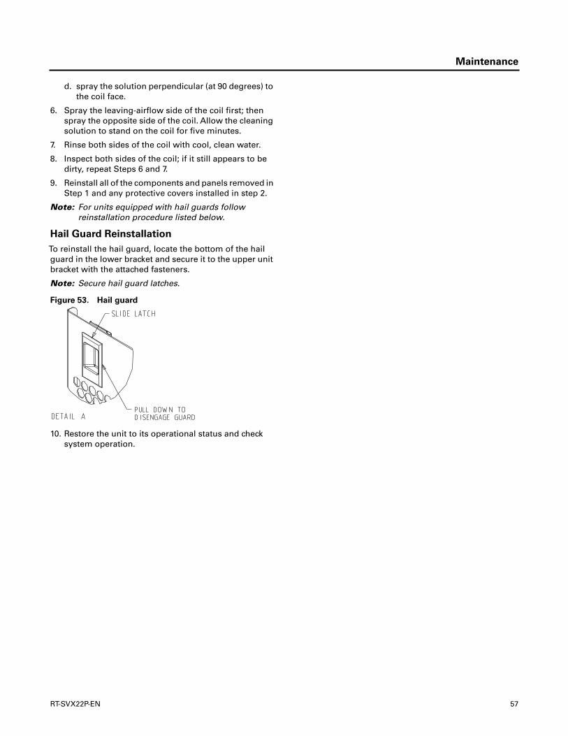
Maintenance
d. spray the solution perpendicular (at 90 degrees) tothe coil face.
6. Spray the leaving-airflow side of the coil first; thenspray the opposite side of the coil. Allow the cleaningsolution to stand on the coil for five minutes.
7. Rinse both sides of the coil with cool, clean water.
8. Inspect both sides of the coil; if it still appears to bedirty, repeat Steps 6 and 7.
9. Reinstall all of the components and panels removed inStep 1 and any protective covers installed in step 2.
Note: For units equipped with hail guards followreinstallation procedure listed below.
Hail Guard Reinstallation
To reinstall the hail guard, locate the bottom of the hailguard in the lower bracket and secure it to the upper unitbracket with the attached fasteners.
Note: Secure hail guard latches.
10. Restore the unit to its operational status and checksystem operation.
Figure 53. Hail guard
RT-SVX22P-EN 57
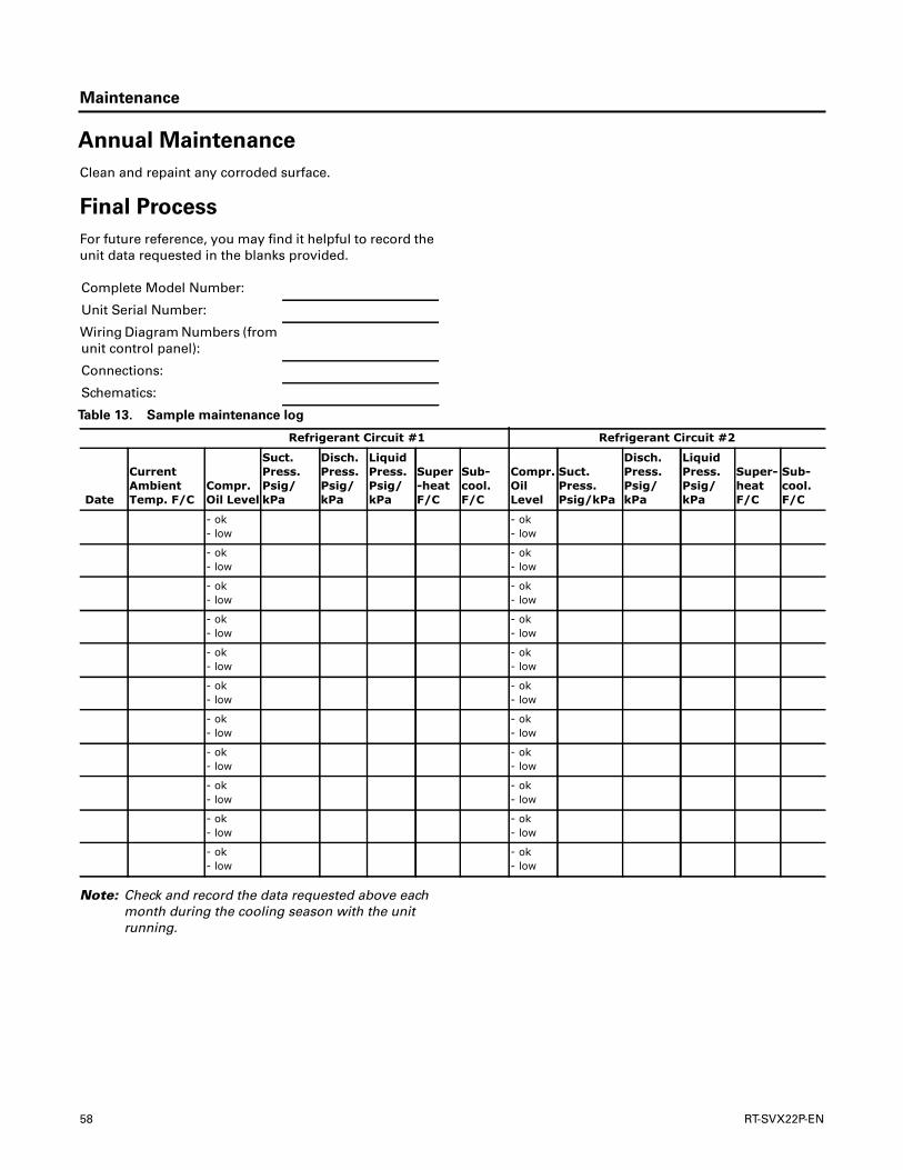
Maintenance
Annual Maintenance
Clean and repaint any corroded surface.
Final Process
For future reference, you may find it helpful to record theunit data requested in the blanks provided.
Note: Check and record the data requested above eachmonth during the cooling season with the unitrunning.
Complete Model Number:
Unit Serial Number:
Wiring Diagram Numbers (fromunit control panel):
Connections:
Schematics:
Table 13. Sample maintenance log
Refrigerant Circuit #1 Refrigerant Circuit #2
Date
Current Ambient Temp. F/C
Compr. Oil Level
Suct. Press. Psig/kPa
Disch. Press. Psig/kPa
Liquid Press. Psig/kPa
Super-heat F/C
Sub-cool. F/C
Compr. Oil Level
Suct. Press. Psig/kPa
Disch. Press. Psig/kPa
Liquid Press. Psig/kPa
Super-heat F/C
Sub-cool. F/C
- ok- low
- ok- low
- ok- low
- ok- low
- ok- low
- ok- low
- ok- low
- ok- low
- ok- low
- ok- low
- ok- low
- ok- low
- ok- low
- ok- low
- ok- low
- ok- low
- ok- low
- ok- low
- ok- low
- ok- low
- ok- low
- ok- low
58 RT-SVX22P-EN
Troubleshooting
ReliaTel™ Control
The RTRM has the ability to provide the service personnelwith some unit diagnostics and system status information.
Before turning the main power disconnect switch “Off”,follow the steps below to check the ReliaTel RefrigerationModule (RTRM). All diagnostics & system statusinformation stored in the RTRM will be lost when the mainpower is turned “Off”.
To prevent injury or death from electrocution, it is theresponsibility of the technician to recognize this hazardand use extreme care when performing serviceprocedures with the electrical power energized.
1. Verify that the Liteport LED on the RTRM is burningcontinuously. If the LED is lit, go to Step 3.
2. If the LED is not lit, verify that 24 VAC is presencebetween J1-1 and J1-2. If 24VAC is present, proceed toStep 4. If 24 VAC is not present, check the unit mainpower supply, check transformer (TNS1). Proceed toStep 3 if necessary.
3. Utilizing “Method 1” or “Method 2” in the “SystemStatus Diagnostic” section, check the following:
• System status
• Heating status
• Cooling status
If a System failure is indicated, proceed to Step 4. If nofailures are indicated, proceed to Step 5.
4. If a System failure is indicated, recheck Step 1 and Step2. If the LED is not lit in Step 1, and 24 VAC is presentin Step 2, the RTRM has failed. Replace the RTRM.
5. If no failures are indicated, use one of theTEST modeprocedures described in the “Unit Start-Up” section tostart the unit.This procedure will allow you to check allof the RTRM outputs, and all of the external controls(relays, contactors, etc.) that the RTRM outputsenergize, for each respective mode. Proceed to Step 6.
6. Step the system through all of the available modes,and verify operation of all outputs, controls, andmodes. If a problem in operation is noted in any mode,you may leave the system in that mode for up to onehour while troubleshooting. Refer to the sequence ofoperations for each mode, to assist in verifying properoperation. Make the necessary repairs and proceed toStep 7 and Step 8.
7. If no abnormal operating conditions appear in the testmode, exit the test mode by turning the power “Off” atthe main power disconnect switch.
8. Refer to the individual component test procedures ifother microelectronic components are suspect.
System Status Checkout
Procedure
“System Status” is checked by using one of the followingtwo methods:
Method 1
If the Zone Sensor Module (ZSM) is equipped with aremote panel with LED status indication, you can check theunit within the space. If the ZSM does not have LED’s, useMethod 2. BAYSENS110*, BAYSENS109*, BAYSENS119*,BAYSENS023A all have the remote panel indicationfeature.The LED descriptions are listed below.
Zone Sensor LED 1 (System)
“On” during normal operation.
“Off” if a system failure occurs or the LED fails.
“Flashing” indicates test mode.
Zone Sensor LED 2 (Heat)
“On” when the heat cycle is operating.
“Off” when the heat cycle terminates or the LED fails.
“Flashing” indicates a heating failure.
Zone Sensor LED 3 (Cool)
“On” when the cooling cycle is operating.
“Off” when the cooling cycle terminates or the LED fails.
WARNING
Hazardous Service Procedures!
The troubleshooting procedures recommended in thissection of the manual could result in exposure toelectrical, mechanical or other potential safety hazards.Always refer to the safety warnings providedthroughout this manual concerning these procedures.Unless specified otherwise, disconnect all electricalpower including remote disconnect and discharge allenergy storing devices such as capacitors beforeservicing. Follow proper lockout/tagout procedures toensure the power can not be inadvertently energized.When necessary to work with live electricalcomponents, have a qualified licensed electrician orother individual who has been trained in handling liveelectrical components perform these tasks. Failure tofollow all of the recommended safety warningsprovided, could result in death or serious injury.
WARNING
Live Electrical Components!
During installation, testing, servicing andtroubleshooting of this product, it may be necessary towork with live electrical components. Have a qualifiedlicensed electrician or other individual who has beenproperly trained in handling live electrical componentsperform these tasks. Failure to follow all electricalsafety precautions when exposed to live electricalcomponents could result in death or serious injury.
RT-SVX22P-EN 59
Troubleshooting
“Flashing” indicates a cooling failure.
Zone Sensor LED 4 (Service)
“On” indicates a clogged filter.
“Off” during normal operation.
“Flashing” indicates an evaporator fan or condensateoverflow failure.
Below is the complete listing of failure indication causes.
System failure
Check the voltage between terminals 6 and 9 on J6, itshould read approximately 32 VDC. If no voltage ispresent, a System failure has occurred. Refer to Step 4 inthe previous section for the recommendedtroubleshooting procedure.
Cooling Failure
• Cooling and heating set point (slide pot) on the zonesensor has failed. Refer to the “Zone SensorTestProcedure” section.
• Zone temperature thermistor ZTEMP on ZTS failed.Refer to the “Zone SensorTest Procedure” section.
• CC1 or CC2 24 VAC control circuit has opened, checkCC1 & CC2 coils, and any of the controls below thatapply to the unit (HPC1, HPC2).
• LPC1 has opened during the 3 minute minimum “ontime” during 4 consecutive compressor starts, checkLPC1 or LPC2 by testing voltage between the J1-1 & J3-2 terminals on the RTRM and ground. If 24 VAC ispresent, the LPC’s has not tripped. If no voltage ispresent, LPC’s has tripped.
Service Failure
• If the supply fan proving switch has closed, the unit willnot operate (when connected to RTOM), check the fanmotor, belts, and proving switch.
• Clogged filter switch has closed, check the filters.
• If the condensate overflow switch is closed, the unitwill not operate. Make sure the float switch is not in atripped condition, and check for an “open” betweenwires connecting to RTOM J6-1, J6-2 (ReliaTel™controls).
Simultaneous Heat and Cool Failure
• Emergency Stop is activated
Method 2
The second method for determining system status is doneby checking voltage readings at the RTRM (J6).The systemindication descriptions and the approximate voltages arelisted below.
System Failure
• Measure the voltage between terminals J6-9 & J6-6.
• Normal Operation = approximately 32 VDC
• System Failure = less than 1 VDC, approximately 0.75VDC
• Test Mode = voltage alternates between 32VDC & 0.75VDC
Heat Failure
• Measure the voltage between terminals J6-7 & J6-6.
• Heat Operating = approximately 32 VDC
• Heat Off = less than 1 VDC, approximately 0.75 VDC
• Heating Failure = voltage alternates between 32VDC &0.75 VDC
Cool Failure
• Measure the voltage between terminals J6-8 & J6-6.
• Cool Operating = approximately 32 VDC
• Cool Off = less than 1 VDC, approximately 0.75 VDC
• Cooling Failure = voltage alternates between 32VDC &0.75 VDC
Service Failure
• Measure the voltage between terminals J6-10 & J6-6.
• Clogged Filter = Approximately 32 VDC.
• Normal = Less than 1 VDC, approximately 0.75 VDCFan Failure = voltage alternates between 32VDC & 0.75VDC.
To use LED’s for quick status information at the unit,purchase a BAYSENS110* ZSM and connect wires withalligator clamps to terminals 6 through 10. Connected eachrespective terminal wire (6 through 10) from the ZoneSensor to the unit J6 terminals 6 through 10.
Note: If the system is equipped with a programmablezone sensor, (BAYSENS119*, or BAYSENS023A),the LED indicators will not function while theBAYSENS110* is connected.
Resetting Cooling and Ignition Lockouts
Cooling Failures and Heating Lockouts are reset in anidentical manner. Method 1 explains resetting the systemfrom the space; Method 2 explains resetting the system atthe unit.
Note: Before resetting Cooling Failures and IgnitionLockouts check the Failure Status Diagnostics bythe methods previously explained. Diagnostics willbe lost when the power to the unit is disconnected.
Method 1
To reset the system from the space, turn the “Mode”selection switch at the zone sensor to the “Off” position.After approximately 30 seconds, turn the “Mode”selection switch to the desired mode, i.e. Heat, Cool orAuto.
60 RT-SVX22P-EN

Troubleshooting
Method 2
To reset the system at the unit, cycle the unit power byturning the disconnect switch “Off” and then “On”.
Lockouts can be cleared through the buildingmanagement system. Refer to the building managementsystem instructions for more information.
ZoneTemperature Sensor (ZTS)
Service Indicator
The ZSM SERVICE LED is a generic indicator, that willsignal the closing of a Normally Open switch at any time,providing the Indoor Motor (IDM) is operating.Thisindicator is usually used to indicate a clogged filter, or anair side fan failure.
The RTRM will ignore the closing of this Normally Openswitch for 2 (±1) minutes.This helps prevent nuisanceSERVICE LED indications.The exception is the LED willflash 40 seconds after the fan is turned “On” if the FanProving Switch is not made.
Clogged Filter Switch
This LED will remain lit the entire time that the NormallyOpen switch is closed.The LED will be turned offimmediately after resetting the switch (to the NormallyOpen position), or any time that the IDM is turned “Off”.
If the switch remains closed, and the IDM is turned “On”,the SERVICE LED will be turned “On” again after the 2 (±1)minute ignore delay.
This LED being turned “On”, will have no other affect onunit operation. It is an indicator only.
Fan Failure Switch
When the “Fan Failure” switch is wired to the RTOM, theLED will remain flashing the entire time the fan provingswitch is closed, indicating a fan failure, and it will shut theunit operations down.
Condensate Overflow Switch
When the “Condensate Overflow Switch” is closed, adrain pan overflow condition is indicated and it will shutunit operations down.
ZoneTemperature Sensor (ZTS)
Test
Note: These procedures are not for programmable ordigital models and are conducted with the ZoneSensor Module electrically removed from thesystem.
Test 1 - ZoneTemperatureThermistor(ZTEMP)
This component is tested by measuring the resistancebetween terminals 1 and 2 on the ZoneTemperatureSensor. Below are some typical indoor temperatures, andcorresponding resistive values.
Test 2 - Cooling Set Point (CSP) andHeating Set Point (HSP)
The resistance of these potentiometers are measuredbetween the following ZSM terminals. Refer to the chartabove for approximate resistances at the given setpoints.
Cool SP =Terminals 2 and 3
Range = 100 to 900 Ohms approximate
Heat SP =Terminals 2 and 5
Range = 100 to 900 Ohms approximate
Test 3 - System Mode and Fan Selection
The combined resistance of the Mode selection switch andthe Fan selection switch can be measured betweenterminals 2 and 4 on the Zone Sensor.The possible switchcombinations are listed below with their correspondingresistance values.
Test 4 - LED IndicatorTest, (SYS ON, HEAT,COOL & SERVICE)
Method 1
Testing the LED using a meter with diode test function.Testboth forward and reverse bias. Forward bias shouldmeasure a voltage drop of 1.5 to 2.5 volts, depending onyour meter. Reverse bias will show an Over Load, or opencircuit indication if LED is functional.
Method 2
Testing the LED with an analog Ohmmeter. ConnectOhmmeter across LED in one direction, then reverse theleads for the opposite direction.The LED should have atleast 100 times more resistance in reverse direction, ascompared with the forward direction. If high resistance in
Table 14. Cooling setpoint and heating setpoint
Zone TemperatureNominal ZTEMP
Resistance
50° F 10.0°C 19.9 K-Ohms
55° F 12.8°C 17.47 K-Ohms
60° F 15.6°C 15.3 K-Ohms
65° F 18.3°C 13.49 K-Ohms
70° F 21.1°C 11.9 K-Ohms
75° F 23.9°C 10.50 K-Ohms
80° F 26.7°C 9.3 K-Ohms
85° F 29.4°C 8.25 K-Ohms
90° F 32.2°C 7.3 K-Ohms
RT-SVX22P-EN 61

Troubleshooting
both directions, LED is open. If low in both directions, LEDis shorted.
Method 3
To test LED’s with ZSM connected to unit, test voltages atLED terminals on ZSM. A measurement of 32VDC, acrossan unlit LED, means the LED has failed.
Relative Humidity SensorTest
This component is measured by measuring the mA outputsignal on the Relative Humidity Sensor.Verify accuracy ofthe sensor annually. If the output reading is 0 mA, firstverify that power is applied to the sensor. A reading of 4mA corresponds to 0% RH and 20 mA corresponds to 100%RH.
Note: Measurements should be made from LED common(ZSM terminal 6 to respective LED terminal). Referto the Zone Sensor Module (ZSM)TerminalIdentification table at the beginning of this section.
Programmable & Digital ZoneSensorTest
Testing serial communication voltage
1. Verify 24VAC is present between terminals J6-14 & J6-11.
2. Disconnect wires from J6-11 and J6-12. Measure thevoltage between J6-11 and J6-12, should be about 32VDC.
3. Reconnect wires to terminals J6-11 and J6-12. Measurevoltage again between J6-11 and J6-12, voltage shouldflash high and low every 0.5 seconds.The voltage onthe low end will measure about 19 VDC, while thevoltage on the high end will measure fromapproximately 24 to 38 VDC.
4. Verify all modes of operation, by running the unitthrough all of the steps in Table 9, p. 45.
5. After verifying proper unit operation, exit the testmode.Turn the fan on continuously at the ZSM, bypressing the button with the fan symbol. If the fancomes on and runs continuously, the ZSM is good. Ifyou are not able to turn the fan on, the ZSM isdefective.
ReliaTel™ Refrigeration Module (RTRM)Default Chart
If the RTCI loses input from the building managementsystem, the RTRM will control in the default mode afterapproximately 15 minutes. If the RTRM loses the Heatingand Cooling setpoint input, the RTRM will control in thedefault mode instantaneously.The temperature sensingthermistor in the Zone Sensor Module is the onlycomponent required for the “Default Mode” to operate.
Unit Operation without a Zone Sensor
This procedure is for temporary operation only.Theeconomizer and condenser fan cycling functions aredisabled.
1. Open and Lock the unit disconnect switch.
2. Remove the Outside Air Sensor (OAS) from thecondenser section of unit.
3. Use two (2) wire nuts, to individually cap the wires.
4. Locate the RTRM (J6). Connect two (2) wires toterminals J6-1 and 2.
5. Connect the sensor (OAS) using two wire nuts to thetwo (2) field supplied wires that were connected toterminals 1 and 2 on J6.
Unit Economizer Control (ECA)
Troubleshooting
ReliaTel™ Control
Verify Economizer Status by Economizer Actuator (ECA)LED indicator:
• OFF: No Power or Failure
• ON: Normal, OK to Economize
• Slow Flash: Normal, Not OK to Economize
• Fast Flash - 1/2 Second On / 2 Seconds Off:
• Error Code: Communications Failure
• Pulse Flash: 2 Seconds On / 1/2 Second Off:
• Error Code:
• 1 Flash: Actuator Fault
• 2 Flashes: CO2 Sensor
• 3 Flashes: RA Humidity Sensor
• 4 Flashes: RATemp Sensor
% RH mA
30 8.8
40 10.4
50 12.0
60 13.6
70 15.2
80 16.8
WARNING
Hazardous Voltage!
Disconnect all electric power, including remotedisconnects before servicing. Follow proper lockout/tagout procedures to ensure the power can not beinadvertently energized. Failure to disconnect powerbefore servicing could result in death or serious injury.
62 RT-SVX22P-EN
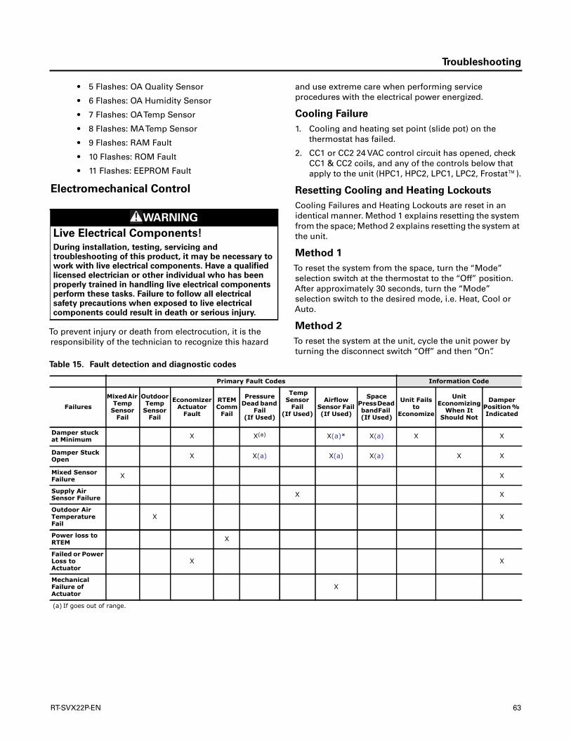
Troubleshooting
• 5 Flashes: OA Quality Sensor
• 6 Flashes: OA Humidity Sensor
• 7 Flashes: OATemp Sensor
• 8 Flashes: MATemp Sensor
• 9 Flashes: RAM Fault
• 10 Flashes: ROM Fault
• 11 Flashes: EEPROM Fault
Electromechanical Control
To prevent injury or death from electrocution, it is theresponsibility of the technician to recognize this hazard
and use extreme care when performing serviceprocedures with the electrical power energized.
Cooling Failure
1. Cooling and heating set point (slide pot) on thethermostat has failed.
2. CC1 or CC2 24 VAC control circuit has opened, checkCC1 & CC2 coils, and any of the controls below thatapply to the unit (HPC1, HPC2, LPC1, LPC2, Frostat™).
Resetting Cooling and Heating Lockouts
Cooling Failures and Heating Lockouts are reset in anidentical manner. Method 1 explains resetting the systemfrom the space; Method 2 explains resetting the system atthe unit.
Method 1
To reset the system from the space, turn the “Mode”selection switch at the thermostat to the “Off” position.After approximately 30 seconds, turn the “Mode”selection switch to the desired mode, i.e. Heat, Cool orAuto.
Method 2
To reset the system at the unit, cycle the unit power byturning the disconnect switch “Off” and then “On”.
WARNING
Live Electrical Components!
During installation, testing, servicing andtroubleshooting of this product, it may be necessary towork with live electrical components. Have a qualifiedlicensed electrician or other individual who has beenproperly trained in handling live electrical componentsperform these tasks. Failure to follow all electricalsafety precautions when exposed to live electricalcomponents could result in death or serious injury.
Table 15. Fault detection and diagnostic codes
Primary Fault Codes Information Code
Failures
Mixed Air Temp
Sensor Fail
Outdoor Temp
Sensor Fail
Economizer Actuator
Fault
RTEM Comm
Fail
Pressure Dead band
Fail (If Used)
Temp Sensor
Fail (If Used)
Airflow Sensor Fail (If Used)
Space Press Dead band Fail (If Used)
Unit Fails to
Economize
Unit Economizing
When It Should Not
Damper Position % Indicated
Damper stuck at Minimum X X(a) X(a)* X(a) X X
Damper Stuck Open X X(a) X(a) X(a) X X
Mixed Sensor Failure X X
Supply Air Sensor Failure X X
Outdoor Air Temperature Fail
X X
Power loss to RTEM X
Failed or Power Loss to Actuator
X X
Mechanical Failure of Actuator
X
(a) If goes out of range.
RT-SVX22P-EN 63

Troubleshooting
Unit Economizer Control (ECA)
Test Procedures
Electromechanical Control
This series of tests will allow you to diagnose, anddetermine where, and if a problem exists in the systemeconomizer operation.Test 1 determines if the problem isin the Unit, or if it is in the ECA.Test 2 tests sensor inputs.Test 3 tests the resistors and sensors. Conduct the tests innumerical order until problem is found.
Test 1
Verifying that the economizer actuator (ECA) is functional:
1. Using the “Test Mode” described in the “System Start-Up” section, put the unit into the economizer modeand verify that the economizer actuator (ECA) drivesfully open (approximately 90 seconds).
2. If the ECA is not driving the dampers, verify that 24VACis between the ECA terminalsTR andTR1 is present. If24 volts is not present, a wiring or terminal problemexists from the control transformer. Make anynecessary repairs, see wiring diagrams totroubleshoot.
3. If 24 VAC is present, adjust the minimum positionpotentiometer fully clockwise. If the actuator does notdrive, the economizer actuator is bad. Replace the ECA.
Test 2
Testing the ECA resistors and sensors
1. Testing the Mixed Air Sensor (MAS). Disconnect thewires connected toT andT1 on the ECA, and;
a. Measure the resistance of the sensor between thewires 180B and 181B.
b. Measure the temperature at the MAS location.Using theTemperature versus Resistance chart,verify the accuracy of the MAS.
Replace the sensor if it is out of range.
2. Testing the Outdoor Air Switch. If the temperature isabove 60 degrees, it will need to be chilled. Measurethe resistance of the sensor on the ECA SO and +.
The resistance should be approximately 390 Ohms.
Replace the Switch if it is open.
Replace the ECA if it is out of range.
3. Testing the R1 Resistance.
Measure the resistance of the sensor on the ECA SRand +.
The resistance should be approximately 420 Ohms.
Replace the ECA if it is out of range.
4. Testing the R2 Resistance.
Measure the resistance of the sensor on the ECA P andP1.
The resistance should be approximately 130 Ohms.
Replace the ECA if it is out of range.
Table 16. Low leak economizer sensor values
Sensor Values Data
Temp °FResistance (K ohms) Temp °F
Resistance(K ohms) Temp °F
Resistance (K ohms)
40 26.097 54 17.847 68 12.435
41 25.383 55 17.382 69 12.126
42 24.690 56 16.930 70 11.827
43 24.018 57 16.491 71 11.535
44 23.367 58 16.066 72 11.252
45 22.736 59 15.654 73 10.977
46 22.132 60 15.253 74 10.709
47 21.530 61 14.864 75 10.448
48 20.953 62 14.486 76 10.194
49 20.396 63 14.119 77 9.949
50 19.854 64 13.762 78 9.710
51 19.330 65 13.416 79 9.477
52 18.821 66 13.078 80 9.250
53 18.327 67 12.752 81 9.030
64 RT-SVX22P-EN

Troubleshooting
Troubleshooting procedures for
Direct Drive Plenum Fan
Prior to troubleshooting, verify all wiring and wiringconnections.The motor has internal protections that willshut down the motor before damage occurs. A powercycle is required to reset some of the internal protections.Before proceeding, power down unit for 1 minute and thenpower on.
Please followsteps sequentially unlessdirected differentlyin solution.
Refer to RT-SVB90*-EN for a ComprehensiveTroubleshooting Guide.
RT-SVX22P-EN 65

Unit Wiring Diagrams Numbers
Note: Wiring diagrams can be accessed using e-Libraryby entering the diagram number in the literatureorder number search field or by contactingtechnical support.
Table 17. Unit wiring diagram numbers
Schematic Type Drawing Number Description
Control
Reliatel™
230,460,575V
4366-7216 THC(037-067)
4366-4568 T(S,H)C(036-060)E/F(1,3,4), ReliaTel Controls, X13 IDM
4366-1026 T(S,H)C(036-090)E/F(3,4,W), ReliaTel Controls, Belt-Drive IDM
4366-1044 TSC(092,102)F(3,4,W), ReliaTel Controls
4366-7433 THC(092-102)F(3,4),TSC120F(3,4,W), ReliaTel Controls
4366-7426 THC120F(3,4), ReliaTel Controls
Electromechanical
4366-8350 T(S,H)C(036-060)E,F(1,3,4), Electromechanical Controls, X13 IDM
4366-8348 T(S,H)C(036-060)E,F(3,4,W), Electromechanical Controls, Belt-Drive IDM
4366-8347 T(S,H)C(072,090)F(3,4,W), Electromechanical Controls
4366-8349 TSC(092,102)F(3,4,W), Electromechanical Controls
4366-8352 THC(092-102)F(3,4),TSC120F(3,4,W), Electromechanical Controls
4366-8351 THC120F(3,4), Electromechanical Controls
Schematic Type Drawing Number Description
Power
Reliatel
230V
4366-7177 THC(037-067) (230V)
4366-4574 T(S,H)C(036-060)E,F (1-Phase)
4366-5161 THC(036-060)E,F (3-Phase), X13 IDM
4366-1037 TSC(092,102)F
4366-7431 (THC092-102, TSC120)F (230V), ReliaTel Controls
4366-7426 THC120F, ReliaTel Controls
460V and/or 575V
4366-7178 THC(037-067) (460V)
4366-5161 THC(036-060)E,F (3-Phase), X13 IDM
4366-1037 TSC(092,102)F
4366-7431 (THC092-102, TSC120)F (460V), ReliaTel Controls
4366-7434 TSC120F (575V), ReliaTel Controls
4366-1020 T(YS,H)C(036-090)E3,4,W, ReliaTel™ Controls
4366-7426 THC120F, ReliaTel Controls
Electromechanical
230V4366-6428 THC120F, Electromechanical Controls
4366-6433 THC(092-102)F, TSC120, Electromechanical Controls
460V and/or 575V
4366-6428 THC120F, Electromechanical Controls
4366-6433 THC(092-102)F4,TSC(120)F4, Electromechanical Controls
4366-6781 TSC120FW, Electromechanical Controls
4366-1020 T(YS,H)C(036-090)E3,4,W, Electromechanical Controls
66 RT-SVX22P-EN

Unit Wiring Diagrams Numbers
Connection
Reliatel™
230V
4366-7336 THC(037) (230V)
4366-8243 THC037E, 17 Plus with Multi-Zone VAV
4366-7338 THC(047-067) (230V)
4366-8245 THC (047,067)E, 17 Plus with Multi-Zone VAV
4366-8251 THC(092-120)E, ReliaTel Controls with Multi-Zone VAV
4366-4559 T(S,H)C(036-060)E,F (1-Phase), ReliaTel Controls
4366-5182 THC(036-060)E,F (3-Phase), ReliaTel Controls, X13 IDM
4366-1509 T(S,H)C(036-060)E,F (3-Phase), ReliaTel Controls, Belt-Drive IDM
4366-1541 T(S,H)C(072,090)F, ReliaTel Controls
4366-7441 THC120F, ReliaTel Controls
4366-1534 TSC(092,102)F, ReliaTel Controls
4366-7443 THC(092-102)F, TSC120F, ReliaTel Controls
4366-8252 THC(092-102)F, TSC120F, ReliaTel Controls with Multi-Zone VAV
460V and/or 575V
4366-8252 THC(092-102)F, TSC120F, ReliaTel Controls with Multi-Zone VAV
4366-7337 THC(037) (460V)
4366-8244 THC037E, 17 Plus with Multi-Zone VAV
4366-7339 THC(047-067) (460V)
4366-8246 THC(047,067)E, 17 Plus with Multi-Zone VAV
4366-5182 THC(036-060)E,F (3-Phase), ReliaTel Controls, X13 IDM
4366-1509 T(S,H)C(036-060)E,F (3-Phase), ReliaTel Controls, Belt-Drive IDM
4366-1541 T(S,H)C(072,090)F, ReliaTel Controls
4366-7441 THC120F, ReliaTel Controls
4366-8251 THC(092-120)E, ReliaTel Controls with Multi-Zone VAV
4366-1534 TSC(092,102)F, ReliaTel Controls
4366-7443 (THC092-102, TSC120)F, (460V), ReliaTel Controls
4366-7445 TSC120F (575V), ReliaTel Controls
4366-8253 TSC120F (575V), ReliaTel Controls with Multi-Zone VAV
Electromechanical
230V
4366-8366 T(S,H)C(036-060)E,F (1-Phase), Electromechanical Controls
4366-8367 THC(036-060)E,F (3-Phase), Electromechanical Controls, X13 IDM
4366-8363 T(S,H)C(036-060)E,F (3-Phase), Electromechanical Controls, Belt-Drive IDM
4366-8365 T(S,H)C(072,090)F, Electromechanical Controls
4366-8368 THC120F, Electromechanical Controls
4366-8364 TSC(092,102)F, Electromechanical Controls
4366-8369 (THC092-102, TSC120)F, (230V), Electromechanical Controls
460V and/or 575V
4366-8367 THC(036-060)E,F (3-Phase), Electromechanical Controls, X13 IDM
4366-8363 T(S,H)C(036-060)E,F (3-Phase), Electromechanical Controls, Belt-Drive IDM
4366-8365 T(S,H)C(072,090)F, Electromechanical Controls
4366-8368 THC120F, Electromechanical Controls
4366-8364 TSC(092,102)F, Electromechanical Controls
4366-8369 (THC092-102, TSC120)F (460V), Electromechanical Controls
4366-8370 TSC120F (575V), Electromechanical Controls
Table 17. Unit wiring diagram numbers (continued)
Schematic Type Drawing Number Description
RT-SVX22P-EN 67

Limited Warranty
Electric Air Conditioner
TCY,TCX,TCC,TCD,TCH,TCM,TCP,TSCandTHC (Parts Only) Models LessThan 20Tons for Residential Use*
This limited warranty is extended byTrane to the originalpurchaser and to any succeeding owner of the realproperty to which the Combination Electric/ Electric AirConditioner is originally affixed, and applies to productspurchased and retained for use within the U.S.A. andCanada.
If any part of your Combination Electric/ Electric AirConditioner fails because of a manufacturing defect withinfive years from the date of the original purchase,Warrantor will furnish without charge the requiredreplacement part.Any local transportation, related servicelabor, diagnosis calls, air filters, refrigerant and relateditems are not included.
If the sealed motor-compressor fails because of amanufacturing defect within five years from the date oforiginal purchase, Warrantor will furnish without chargethe required replacement compressor. Any localtransportation, related service labor, diagnosis calls,refrigerant and related items are not included.
If the steel heat exchanger fails because of amanufacturing defect within the sixth through tenth yearfrom the date of original purchase, Warrantor will furnishwithout charge a replacement heat exchanger. Any localtransportation, related service labor and diagnosis callsare not included.
In addition, if the optional, factory installed, stainless steelheat exchanger fails because of a manufacturing defectwithin ten years from the date of start-up, Warrantor willfurnish without charge a replacement heat exchanger.Anylocal transportation, related service labor and diagnosiscalls are not included.
This limited warranty does not cover failure of yourcombination Electric/ Electric air conditioner if it isdamaged while in your possession, failure attributable orcaused by unreasonable use of the combination Electric/Electric air conditioner and/or failure to properly maintainthe combination Electric/ Electric air conditioner as setforth in the Use and Care manual.
This limited warranty applies to product installed on orafter 10/1/2001 where product is manufactured after 1/1/2000.This limited warranty is not retroactive to anyinstallations prior to 10/1/2001 or on product producedprior to 2000.
THE LIMITED WARRANTY AND LIABILITY SET FORTHHEREIN ARE IN LIEU OF ALL OTHER WARRANTIES ANDLIABILITIES, WHETHER IN CONTRACT OR INNEGLIGENCE, EXPRESS OR IMPLIED, IN LAW OR IN FACT,INCLUDING IMPLIED WARRANTIES OFMERCHANTABILITY AND FITNESS FOR PARTICULAR
USE, AND IN NO EVENT SHALL WARRANTOR BE LIABLEFOR ANY INCIDENTAL OR CONSEQUENTIAL DAMAGES.
Some states do not allow limitations on how long animplied limited warranty lasts or do not allow theexclusion or limitation of incidental or consequentialdamages, so the above limitation or exclusion may notapply to you.This limited warranty gives you specific legalrights, and you may also have other rights which vary fromstate to state.
Parts will be provided by our factory organization throughan authorized service organization in your area listed in theyellow pages. If you wish further help or informationconcerning this limited warranty, contact:
Trane
2701 Wilma Rudolph Blvd.
Clarksville,TN 37040-1008
Attention: Manager, Product Service
GW-618-4001
*This limited warranty is for residential usage of thisequipment and not applicable when this equipment isused for a commercial application. A commercial use isany application where the end purchaser uses the productfor other than personal, family or household purposes.
68 RT-SVX22P-EN
Limited Warranty
Electric Air Conditioner
TCY,TCX,TCC,TCD,TCH,TCK,TCM,TCP,TSC andTHC (Parts Only) Models LessThan 20Tons for Commercial Use*
This warranty is extended byTrane to the originalpurchaser and to any succeeding owner of the realproperty to which the Combination Electric/ Electric AirConditioner is originally affixed, and applies to productspurchased and retained for use within the U.S.A. andCanada.There is no warranty against corrosion, erosion ordeterioration.
If any part of your Combination Electric/ Electric AirConditioner fails because of a manufacturing defect withinone year from the date of the original purchase,Warrantorwill furnish without charge the required replacement part.
In addition, if the sealed motor-compressor fails becauseof a manufacturing defect within the second through fifthyear from the date of original purchase, Warrantor willfurnish without charge the required replacementcompressor.
If the steel heat exchanger fails because of amanufacturing defect within the second through fifth yearfrom the date of original purchase, Warrantor will furnishwithout charge a replacement heat exchanger.
In addition, if the optional, factory installed, stainless steelheat exchanger fails because of a manufacturing defectwithin ten years from the date of start-up, Warrantor willfurnish without charge a replacement heat exchanger.Anylocal transportation, related service labor and diagnosiscalls are not included.
Warrantor’s obligations and liabilities under this warrantyare limited to furnishing F.O.B. Warrantor factory orwarehouse at Warrantor designated shipping point,freight allowed to Buyer’s city, replacement parts forWarrantor’s products covered under this warranty.Warrantor shall not be obligated to pay for the cost of lostrefrigerant. No liability shall attach to Warrantor untilproducts have been paid for and then liability shall belimited solely to the purchase price of the equipmentunder warranty shown to be defective.
THEWARRANTY AND LIABILITY SET FORTH HEREIN AREIN LIEU OF ALL OTHER WARRANTIES AND LIABILITIES,WHETHER IN CONTRACT OR IN NEGLIGENCE, EXPRESSOR IMPLIED, IN LAW OR IN FACT, INCLUDING IMPLIEDWARRANTIES OF MERCHANTABILITY AND FITNESS FORPARTICULAR USE, AND IN NO EVENT SHALLWARRANTOR BE LIABLE FOR ANY INCIDENTAL ORCONSEQUENTIAL DAMAGES.
Some states do not allow limitations on how long animplied warranty lasts or do not allow the exclusion orlimitation of incidental or consequential damages, so theabove limitation or exclusion may not apply to you.Thiswarranty gives you specific legal rights, and you may alsohave other rights which vary from state to state.
Trane
2701 Wilma Rudolph Blvd.
Clarksville,TN 37040-1008
Attention: Manager, Product Service
GW-606-4800
*This warranty is for commercial usage of said equipmentand not applicable when the equipment is used for aresidential application. Commercial use is any applicationwhere the end purchaser uses the product for other thanpersonal, family or household purposes.
**A 5 year limited warranty is provided for the optional"Low Leak" economizer when combined with theadditional FDD (Fault Detection & Diagnostics) option.
RT-SVX22P-EN 69


The manufacturer optimizes the performance of homes and buildings around the world. A business of Ingersoll Rand,the leader in creating and sustaining safe, comfortable and energy efficient environments,the manufacturer offers abroad portfolio of advanced controls and HVAC systems, comprehensive building services, and parts. For moreinformation, visit www.IRCO.com.
The manufacturer has a policy of continuous product and product data improvement and reserves the right to change design and specifications without notice.
We are committed to using environmentally
conscious print practices that reduce waste.
© 2015Trane All rights reserved
RT-SVX22P-EN 27 April 2015
Supersedes RT-SVX22N-EN (11 July 2014)