Installation Manual for the KPS Petrol Pipe System™ · PDF fileInstallation Manual for...
55
KPS System Manual – Version 6.0 CONTENTS About this manual: KPS reserves the right to update and revise this manual from time to time. The latest issue is always published on www.kpsystem.com and KPS accepts no liability for installation performed according to an outdated manual. Installation Manual for the KPS Petrol Pipe System™ Content: 1. Introduction ............................................................................ 2 2. General requirements ............................................................ 5 3. Product Descriptions ........................................................... 10 4. Handling................................................................................ 12 5. Cutting .................................................................................. 16 6. Welding ................................................................................. 22 7. Pressure Testing ................................................................... 31 8. Backfill .................................................................................. 33 9. Pipe Welding Machine ......................................................... 34 10. Installation Examples ........................................................ 35
Transcript of Installation Manual for the KPS Petrol Pipe System™ · PDF fileInstallation Manual for...

KPS System Manual – Version 6.0 CONTENTS
About this manual: KPS reserves the right to update and revise this manual from time to time. The latest issue is always published on www.kpsystem.com and KPS accepts no liability for installation performed according to an outdated manual.
Installation Manual for the KPS Petrol Pipe System™
Content:
1. Introduction............................................................................ 2
2. General requirements............................................................ 5
3. Product Descriptions ........................................................... 10
4. Handling................................................................................ 12
5. Cutting .................................................................................. 16
6. Welding ................................................................................. 22
7. Pressure Testing ................................................................... 31
8. Backfill .................................................................................. 33
9. Pipe Welding Machine......................................................... 34
10. Installation Examples ........................................................ 35

KPS System Manual – Version 6.0 1 . INTRODUCTION
1 . INTRODUCTION The KPS Petrol Pipe System™.......................................................................2
KPS Product reference manual .....................................................................2
High Density Polyethylene Pipe.....................................................................3
Multi-layer Pipe ..............................................................................................3
KPS Conductive Pipe .....................................................................................3
KPS Secondary Contained Lined Pipe..........................................................3
The KPS Petrol Pipe System™ The KPS Petrol Pipe System™ is a comprehensive range of products manufactured by Kungsörs Plast AB, a Swedish company with more than 25 years experience of manufacturing polyethylene pipes and fittings for the petroleum industry. KPS is represented worldwide by a network of partners, providing an international 24 hour back up service. The KPS Petrol Pipe System™ is a state-of-the-art, total solution to handling liquid fuel through a polyethylene pipework system and has built-in, active awareness of the environment. The KPS product range is expanding and developing continuously to adapt and conform to the ever more stringent demands of the market. By using state-of-the-art technology, the company offers highly competitive, long-term solutions with designs that have been developed to eliminate all leakage. Zero tolerance is the basis of all our development work. The wide range of KPS products ensures that whatever your requirements you will find here the most appropriate solution. Whether working on suction or pressure systems, offset fills, vent lines or vapour recovery, we will always provide you with products you can trust. Kungsörs Plast AB is certified to ISO 9001 and ISO 14001.
KPS Product Reference Manual Detailed descriptions, material properties and dimensions are given in the KPS Product Reference Manual issued electronically and available upon request.
2

KPS System Manual – Version 6.0 1 . INTRODUCTION
Polyethylene Pipe Polyethylene has excellent life expectancy – far above any other polymer used for underground pipework. KPS demonstrates this by offering a 30-year guarantee on all items manufactured by KPS and a 15 year guarantee on complete systems. Polyethylene pipes are easy to install and are more resistant to puncture from sharp objects than any other polymer pipes. The KPS Petrol Pipe System™ is designed from 10 bar primary line classed pipe which means that the pipe is subjected to a momentary pressure test at 30 bar before being put into service.
Multi-layer Lined Pipe There are multiple layers. The innermost and second layers act together as a permeation barrier, preventing hydrocarbons from diffusing through the pipe wall (the rate of permeation is so small that it cannot be measured). The outer layer is of high strength polyethylene providing a strong outer case to ensure a long life. To achieve even greater safety the multi-layer lined pipe may be placed inside an additional high strength pipe to protect the primary pipe from damage thus preventing possible leaks. This is known as a coaxial pipe or ‘a pipe in a pipe’.
KPS Multi-layer Lined Conductive Pipe KPS multi-layer lined conductive has been developed to meet the latest technical and safety requirements in Europe. All liquids flowing in pipes cause a build up of static electricity. To avoid the risk of spark ignition KPS has developed a polyethylene conductive pipe system which can be earthed. KPS multi-layer lined conductive has been tested by PTB (Physikalische-Technische-Bundesanstalt) in accordance with the German regulations on flammable liquids and avoidance of static electricity. KPS conductive was found to be well within the requirements. Also the pipe’s performance is unchanged, guaranteeing the same excellent performance as all other KPS products.
KPS Secondary Contained Lined Pipe KPS Integrated Secondary Contained Pipe is a development of earlier KPS Systems. The KPS Patented Integrated Secondary Contained fittings design, which has been developed ‘in house’, reduces to a minimum the number of components used in an installation. This reduces the assembly time and results in a much more cost-effective installation.
3

KPS System Manual – Version 6.0 1 . INTRODUCTION
IMPORTANT NOTICE
The KPS Petrol Pipe System™ has been developed to offer users a cost effective system which will provide reliable performance over many years. Careful attention has been paid to minimising the environmental impact during manufacture and during operation. As a result of this careful development work and stringent control of the manufacturing processes, KPS is able to guarantee all components manufactured by KPS for 30 years from the date of despatch and to guarantee each installation for 15 years from the date of completion. To ensure that these high standards are maintained and to protect the environment it is essential that all handling, storage and installation work be performed strictly in accordance with the requirements specified in this manual. It is a condition of all guarantees that the installation be undertaken by a KPS certified installer.
4

KPS System Manual – Version 6.0 2 . GENERAL REQUIREMENTS
2 . GENERAL REQUIREMENTS Application ......................................................................................................5
Arrangement of pipes .....................................................................................5
Installation of pipes and fittings ....................................................................6
Inspection, testing and certification ..............................................................7
Registration .....................................................................................................8
Backfill.............................................................................................................8
Application
All installations are to be in accordance with the arrangements shown in the typical examples – see section 10, Installation Examples. KPS Multi-layer lined (KP-E), Multi-layer lined Conductive (KP-EC) or Secondary Contained lined (KP-SC) can be used in all fuel system applications. For product descriptions see section 3, Product Descriptions.
Arrangement of pipes Pipes must be installed on a bed of at least 150 mm of pea gravel (0-22 mm). Stones or sharp objects must not come into contact with the pipe. Pipes must be laid on a gradient of at least 1% falling back to the tank unless otherwise specified by the inspecting authority. In vapour recovery lines it is essential to prevent the accumulation of condensate in pipe dips and to avoid trapping vapour in low sections or forming vapour locks. Where two or more pipes run in a trench the minimum clearance between adjacent pipes is 100 mm. The minimum clearance between a pipe and the side of a trench is 200 mm.
Pea gravel φ0-22mm
100 mm
150 mm
200 mm
Asphalt or other pavement Top fill (dug up material)
300 mm
5

KPS System Manual – Version 6.0 2 . GENERAL REQUIREMENTS
Allowance is to be made for the thermal expansion of pipes. The expansion coefficient is 0.2% per 10K (10ºC or 18ºF). Wherever possible pipes should be laid in slow curves to absorb thermal expansion. The minimum bend radii for curved pipes are: Min bend Radius (mm) KP 25 500 KP 32 640 KP 54 1080 KP 63 1260 KP 75/63 1500 KP 90 1800 KP 110 2200 KP 125/110 2500 KPS recommends that KP 90, KP110 and KP125/110 are handled as straight pipes only. Pipes and fittings may only be cut within the limits given in Section 5, Cutting. Where conductive piping is installed the system must be connected to earth at every point where the piping ends with a fitting type KP C11, KP C12, KP 5, KP 6 or KPW. The earth cable shall have an area of at least a 6 mm2 and a maximum resistance to earth of 10 ohms. It can be connected to an earthing point at the dispenser, the steel tank or by an earth rod driven into the ground, not less than 1500 mm deep. See also Inspection, testing and certification later in this section. KPS recommends that fill pipes be installed with conductive pipe (ground to earth) in order to avoid the risk of problems related to electrostatic discharges.
Installation of pipes and fittings Handling All materials should be stored in the original packing until required. The surface of the storage area shall contain no sharp objects. For other requirements see Section 4, Handling. Cutting All pipes and fittings should be cut using KPS approved cutting tools. Contact the KPS office for product details. For other requirements see Section 5, Cutting. Welding All welding should be undertaken using a KPS approved welding machine and welding fixtures. For other requirements see Section 6, Welding. Pressurised pipe system Special attention must be paid to the installation of pressurised systems.
6

KPS System Manual – Version 6.0 2 . GENERAL REQUIREMENTS
Direct burial with backfill in accordance with this manual is strongly recommended. The use of an outer “chase” or duct pipe around the system is not recommended. KPS strongly recommends that pressurised systems with secondary containment be equipped with a leak detection system. An adequate and cost effective alternative is when the interstitial space is filled with water (when necessary mixed with anti-freeze agent). When a manometer is applied (set to 0 bar) a continuous check can be performed at regular intervals. A change in pressure indicates the systems needs to be checked for functionality. The interstitial space of a secondary contained system must always be sealed using KP T-fittings at both ends and the ends is best accessible in the chambers at both ends of the system. The fixation of the piping system is extra important in pressurised systems. If the piping system is not thoroughly fixed the operating pressure and hammer effects (of up to 12 Bar) that occur during operation can damage the system.
The use of KPS flexible hoses under the dispenser is recommended and steel pipe risers shall not be used. Rigid risers in a flexible system may damage the shear valve. For proper design of pressure systems always consult KPS for specific advice.
Inspection, testing and certification Pressure testing On completion of all work on the piping but before any backfilling is undertaken the system is to be pressure tested in accordance with the requirements of section 7, Pressure Testing. Testing Conductive pipes and components All conductive components in a KPS Conductive system must be electrically connected to each other by a KPCC connector (see right). Ground the pipe to earth. Finally, after the earth cables are connected, test the conductivity of the piping. The permitted resistances in the systems are: KP 110EC 80 kohm/m KP 90EC 100 kohm/m KP 63EC 140 kohm/m KP 54EC 170 kohm/m Certification After completing the above tests a final inspection is made prior to backfilling. The KPS certified installer should make a formal inspection and complete the KPS Installation Checklist – see page 8.
7

KPS System Manual – Version 6.0 2 . GENERAL REQUIREMENTS
Registration The KPS Installation Checklist is the basis of the guarantee. The customer shall retain these for a period of 30 years from the date of installation and shall make them available at all times on reasonable notice for inspection by authorised agents of Kungsörs Plast AB who shall be entitled to a copy of thereof on request.
Backfill Backfilling may be undertaken only after satisfactory completion of pressure testing and after approval by the KPS certified installer. Backfill is to be performed in accordance with Section 8, Backfill.
IMPORTANT NOTICE
Improper backfill may damage the pipe!
8

KPS System Manual – Version 6.0 2 . GENERAL REQUIREMENTS
All KPS products were checked upon arrival at the site and free from freight and handling
damages.
All KPS products were handled with care during unloading and installation.
All pipe trenches were excavated to provide a minimum of 10-cm free space on either side of every pipe.
All pipes have been installed on a smooth, more than 10-cm, thick, bed of pea gravel (0-22mm).
All KPS pipes were cut squarely with KPS recommended pipe cutters, not a hacksaw.
All pipes were installed in accordance with the KPS installation manual in order to allow for expansion and contraction.
All pipe-ends were dry and thoroughly cleaned with emery cloth and acetone before welding.
All welding sockets have been signed and welded in accordance with the KPS installation manual.
Pressure Test has been performed in accordance with the KPS Installation manual and no leaks were detected.
All parts in the pipe work system are KPS products or products distributed by KPS and were installed in accordance with the KPS installation manual.
All refilling material consists of fine gravel (less than 22 mm) and the refilling has been performed according to KPS installation manual.
Installing Contractor acknowledges that the warranty will be void unless a Certified Installer, i.e. trained by a KPS approved instructor, has carried out the installation.
Conductivity test on all pipes is performed according to the KPS manual (applies only when KPS conductive pipes are used).
____________________________________ ___________________________________ Certified Installer (signature and company name) Installing Contractor (signature and
company name) ____________________ ____________ _______________________ ___________ Print Name Date Print Name Date
KPS Petrol Pipe System
Installation Check List
TO BE COMPLETED BY THE INSTALLING CONTRACTOR AND TO BE FILED BY THE DISTRIBUTOR DURING THE WARRANTY PERIOD
Installing Contractor information:
Installer: ______________________________
Address: ______________________________
______________________________
Phone: ______________________________
Contact: ______________________________
Site Information:
Owner: ______________________________
Site address: ______________________________
______________________________
Phone: ______________________________
Contact: ______________________________
9

KPS System Manual – Version 6.0 3 . PRODUCT DESCRIPTIONS
3 . PRODUCT DESCRIPTIONS
KPS Petrol Pipe System™ product range ..................................................10
Fittings and accessories ................................................................................11
Tools...............................................................................................................11
KPS Petrol Pipe System™ product range The KPS Petrol Pipe System™ product range comprises three classes of polyethylene pipes and the associated fittings:
• Multi-layer lined pipe
• Multi-layer lined conductive pipe
• Secondary Contained lined pipe
In general pipes are joined together and fittings are joined to pipes by electrofusion welding. Fittings are supplied with moulded-in heating elements. Mechanical joints and fittings and fittings for polymer to metal transition are included in the range. KPS also supplies the cutting and welding equipment required to ensure that installation work can be carried out correctly and efficiently. Multi-layer lined and Secondary Contained lined pipe (KP-E) The Multi-layer lined pipe has several layers. The innermost layers form a permeation barrier. The outer layer is of strong polyethylene to provide strength and resistance to puncturing. It is used to contain the flow of liquid fuels. To provide additional security the multi-layer lined pipe can be inserted in a further polyethylene pipe to provide a secondary contained lined piping system.
10

KPS System Manual – Version 6.0 3 . PRODUCT DESCRIPTIONS
Multi-layer lined conductive pipe (KP-EC) This is multi-layer lined pipe with an additional conductive inner layer. The system provides for all pipe surfaces in contact with the liquid to be grounded to earth. This pipe is used to contain the flow of liquid fuels and to prevent the accumulation of static electricity thereby avoiding the risk of sparking. Secondary Contained Lined Pipe (KP-SC) This system is used to contain the flow of liquid fuels but provides additional environmental protection and the possibility to monitor the whole system for leakage. Multi-layer lined pipe (primary pipe) is enclosed in a larger polyethylene pipe (secondary pipe). A controlled, interstitial space is provided between the primary and secondary pipes and specially developed fittings ensure that continuity is maintained in this space throughout the system, which enables monitoring with a leak detection device.
Fittings and accessories For each of the above classes there is a comprehensive range of fittings and accessories to make up a complete piping system. The range of sizes and the relevant fittings are listed on the following pages under Product specification references. Detailed descriptions, material properties and dimensions are given in the KPS Product Reference Manual, a separate publication available electronically upon request.
Tools KPS supplies special tools for cutting and welding all of the above pipe systems. The tools are listed with further details in the KPS Product Reference Manual issued electronically and available upon request.
11

KPS System Manual – Version 6.0 4 . HANDLING
4 . HANDLING
Introduction ..................................................................................................12
Transportation ..............................................................................................12
Loading/Unloading .......................................................................................13
Releasing Coils ..............................................................................................13
On site/Storing the pipe................................................................................13
Summary of Handling and Storage requirements .....................................15
Introduction All components in the KPS Petrol Pipe System™ are of the highest quality, resilient and are easy to handle. However care must always be taken to avoid damage to the pipe surfaces during transport, handling and storage.
Transportation • Pipes and ancillary fittings for the KPS Systems are delivered in
protective packaging to avoid any damage during transportation. Deliveries should be made on a flat bed vehicle, free from any sharp objects.
• When loading pipes/racks and coils onto the truck, make sure that the racks and coils are stacked in a proper way.
• Pipes/Coils should not protrude from the surface on which they
are loaded.
• Pipe/Coils should be set down horizontally onto the truck bed, use ropes or similar equipment to harness the load.
12

KPS System Manual – Version 6.0 4 . HANDLING
Loading/Unloading • A rack or coil is best lifted with a fork truck. Where forklifts are
used to off load coils, the forks should be protected to avoid damage to the coil outer surfaces.
• When lifting pipe bundles by crane, wide slings must be used. Do not use chains or hooks.
• Racks and bundles may be handled using a forklift and coils manhandled by a minimum of two people.
• When pipes/racks and coils are loaded/unloaded with a forklift-truck or cranes, make sure to pick up the load at their centre-points.
• Make sure that the load doesn’t scrape along the edge of the truck bed or against any other sharp object.
• Pipe/Coils should be set down gently and horizontally onto the ground.
• Make sure to take any necessary step to prevent pipe damage during loading/unloading.
Releasing Coils
IMPORTANT NOTICE
Releasing coils is hazardous. When pipes are coiled energy is stored in the coil and incorrect release can cause injury. To avoid this, use two people to secure the pipe end and coil. Remove the restraining bands carefully and with a rope slipknot.
On site/Storing the pipe • Pipes are delivered in straight lengths or in coils of 30 m to 200
m. All pipe ends are protected with end caps that should remain in place until the pipe is used for welding.
• Coiled pipes are wrapped in plastic. When receiving a delivery,
make sure that the wrapping is undamaged. Do not throw or drag the coils from the delivery vehicle and keep them stored on firm, level ground.
13

KPS System Manual – Version 6.0 4 . HANDLING
• Straight lengths are packed in wooden racks. Always keep the pipes in the racks until required for installation. Alternatively, stack them in a pyramid, not more than three metres high, with the bottom layer fully restrained by wedges. If possible, the bottom layer of pipes should be laid on timbers, at approximately one metre centres, to protect the pipes from sharp objects etc.
• Bundled packs of pipes should be stored on clear, level ground, supported by timbers. Never stack the bundles more than three metres high.
• Always store pipes, coils on firm, level ground, able to withstand the weight of the pipes and lifting gear and devoid of sharp objects.
• Never store KPS Pipes without end caps and in direct exposure to sunlight.
IMPORTANT NOTICE
Exposure to UV rays from the sun may damage the lining. Trucks or heavy plant equipment running over pipes can cause internal damage. Deep scratches, more than 10% of the wall thickness, or marks on the outside will weaken the pipe and are grounds for invalidating the guarantee. Small ancillary fittings and sockets are delivered in plastic bags, within boxes. Upon arrival at site, all boxes and materials should be checked for signs of damage. All fittings and sockets should be kept in the plastic bags until ready for use. The plastic bag protects the fittings and sockets from contamination and oxidation. Coiled pipe should be unrolled and straightened the day before use for relaxation and easier handling. During cold conditions coiled pipe should be pre-heated to room temperature for easier handling.
14

KPS System Manual – Version 6.0 4 . HANDLING
Summary of Handling and Storage requirements
ALWAYS • Use wide, non-metallic, slings for lifting materials (i.e.
Polypropylene or Nylon).
• Store pipes on flat, firm ground, able to withstand the weight of the materials and lifting gear.
• Keep pipes and fittings well away from sharp objects and intense heat.
• Keep protective packaging intact until materials are required for use.
• If surface damage exceeds 10% of the material thickness, the damaged section should be rejected.
• Under cold conditions, pre-heat coiled pipe to room temperature.
• Store pipes under cover.
NEVER • Throw/drop pipes or fittings from delivery vehicle.
• Use metal slings, hooks or chains when handling pipes.
• Drag or roll individual pipes, bundles or coils.
• Stack bundles more than three metres high.
• Release coils carelessly
• Expose pipes or fittings to prolonged sunlight.
15

KPS System Manual – Version 6.0 5 . CUTTING
5 . CUTTING Introduction ..................................................................................................16
Cutting tools ..................................................................................................17
Cutting single pipes.......................................................................................17
Cutting formed bends...................................................................................18
Cutting Secondary Containment pipes .......................................................18
Cutting Secondary Containment bends ......................................................20
Introduction
To ensure that the KPS Petrol Pipe System™ can be assembled correctly it is important that the cutting of the pipes and fittings are to the required length and that preparation is carried out in accordance with KPS procedures. To ensure a high quality joint, it is important that the pipes are cut square. Only then can the cut end be properly joined to other parts in the KPS Petrol Pipe System™. Cutting is best achieved by the use of a KPS pipe cutters. These tools give a clean and square cut without burrs.
IMPORTANT NOTICE
Do not cut the pipe with a saw-edged blade.
The following cutting instructions explain the type of cutting tools that can be used, how to use them, restrictions and important measurements when cutting KPS components. It is important to note that formed products in the KPS System must not be cut too close to the curved section, as this will prevent them from fitting correctly into the welding fitting. In the Secondary Containment System, the inner pipe has to protrude a specified distance beyond the outer pipe to suit both welding areas in the KP- 2 SC and KP-T SC welding sockets. Further details are given below in ‘Cutting Secondary Containment Pipes’.
16

KPS System Manual – Version 6.0 5 . CUTTING
Cutting tools Cutting Scissors The KPS cutting scissors can cut KP pipes up to 63 mm diameter. They are fast and reliable and ensure a clean and square cut. (Spare blades are available from your KPS Petrol Pipe System™ distributor.) Rotating pipe cutters The KPS rotating pipe cutter is for pipe diameters 48 mm to 125 mm. These pipe cutters are the most reliable tools for ensuring a clean, square cut without deformation of the roundness of the pipe. (Spares are available from your KPS distributor.)
Cutting single pipes When cutting single wall pipes, make sure that the pipe ends are cut squarely. Preparation, careful handling and correct application of the cutting tools will ensure a square and clean cut that is the basis of a quality weld. Scissors: When cutting, position the scissors with one blade on top of the pipe and move them forward until they make contact with the pipe. Check that the handles are square to the pipe and that the blades line up square. Then proceed with the cutting. Rotating pipe cutters: To operate, depress the release nut and open the cutter. Place it with the rollers under the pipe, bring the cutting wheel into contact with the pipe and turn the cutting wheel feed knob clockwise half a turn after the cutting wheel brushes against the pipe. Rotate the cutter twice around the pipe and then, for each further revolution, turn the knob about 20º to press the cutting wheel further into the pipe. Repeat until the cut has been completed.
17

KPS System Manual – Version 6.0 5 . CUTTING
Cutting formed bends The bends are formed from KPS multi layer pipe, KP-E or KP-EC. KP 3- F/FC; KP 3- FL/FCL must not be cut too close to the curved section see illustration below. 90º bends, Formed bends KP 3 On either side of the bent section, the length from the elongation of one straight leg to the cut on the other straight leg must be of minimum dimensions shown below: Prod nr Ø A B min length KP 3-54 54 220 mm KP 3-63 63 250 mm KP 3-90 90 330 mm KP 3-110 110 370 mm
45º bends, KP 4 These bends must not be shortened.
B min
18

KPS System Manual – Version 6.0 5 . CUTTING
Cutting Secondary Containment pipes Cutting Secondary Containment pipes for use with KP-2 SC welding sockets The Secondary Containment (SC) pipes have to be cut with the inner pipe protruding from the outer pipe to allow correct fitting of the KP 2-SC integrated welding socket. This is where both the inner and outer pipes are welded in one operation. The black inner pipe shall be longer than the green outer pipe in accordance with the illustrations to the right.
Cutting Secondary Containment pipes for use with KP T75/63SC transition fitting When the KP T75/63 SC integrated transition fitting is used, the black inner pipe must be even longer to allow space for accommodating a single pipe KP 2-63 welding socket outside the KP T75/63 SC fitting. See drawing below illustrating the minimum lengths. Minimum length: 75/63SC L=130 mm
40mm
CKP 75/63 S
65mm
KP 125/110SC
L
IMPORTANT NOTICE
Joining two primary pipes using a KP T75/6
3SC is not allowed!
19

KPS System Manual – Version 6.0 5 . CUTTING
Cutting Secondary Containment pipes for use with KP T125/110SC-L transition fitting When the KP T125/110SC-L integrated transition fitting is used it is possible to make a joint inside the fitting. See drawing below.
20

KPS System Manual – Version 6.0 5 . CUTTING
Cutting Secondary Containment bends 90º bends, KP 3-SC Bends must not be cut too close to the curve. On either side of the bent section, the length from the elongation of one straight leg to the cut on the other straight leg must be of minimum dimensions shown below:
B-min
Dimensions on illustration to the right: Product no. B-min KP 3-125/110SC 450 mm KP 3-75/63SC 250 mm KP 3-125/110SCEC 450 mm KP 3-75/63SCEC 250 mm 45º bends, KP 4-SC These bends must not be shortened.
21

KPS System Manual – Version 6.0 6 . WELDING
6 . WELDING Introduction...................................................................................................22
The Process....................................................................................................23
Preparing the weld........................................................................................23
Welding Single Wall Pipes ...........................................................................24
Welding Secondary Contained pipes, KPT-fitting.....................................26
Welding Secondary Contained pipes, KP2 SC-fitting ...............................29
Introduction
This is a general instruction for welding KPS pipe designs and welding fittings. Due to the hazardous area where the welding procedure takes place, please note:
WARNING
Do not weld where there is risk of flammable liquids or vapours. Always ensure that petrol or petrol vapours have been completely removed before welding.
Preparation for welding of the pipes and fittings is extremely important. All loose dirt or surface contamination should be removed using a lint free cloth or paper towel. Surface oxidation should be removed from the pipe over the entire area that is to be welded. This is an essential procedure and should be achieved by abrading the fusion area with emery cloth.
IMPORTANT NOTICE
Do not use sandpaper as a substitute for emery cloth.

KPS System Manual – Version 6.0 6 . WELDING
The welding fitting should be removed from its packing and checked that it is clean. It should not be touched, abraded or come into contact with contaminated material such as silicones, lanoline from human skin or other greasy substances. Use a cloth moistened with acetone to wipe clean the prepared pipe, fitting and the bore of the welding fitting. For detailed information on how to use the welding machine, see Section 9.
The Process Polyethylene pipes and fittings in the KPS system are joined by electrofusion welding. The method is suitable for use on an installation site, because it is not sensitive to weather conditions. However, all joints must be kept dry and clean during the welding process. The ambient temperature when welding can be between -15ºC and +45ºC (-5ºF and +110ºF). The lower temperatures are applicable only under calm, protected conditions. The principle of electrofusion welding is that a resistance wire just below the inner surface of the welding fitting is heated to a temperature sufficient to melt the PE (polyethylene) material on the outside of the pipe and on the inside of the fitting. The temperature reaches about 200ºC. Heat transfer in the polyethylene is slow and only the material in the vicinity of the wire is melted. The polyethylene expands during heating and the pressure in the fusion area increases as the surrounding cold material prevents the melt from expanding. Thus, a homogenous and strong fusion weld is created. The power, energy and welding times are automatically calculated and applied when KPS welding machines are used. Other welding machines must not be used.
Preparing the weld Before starting the pipe jointing process, check that the design specification of the piping conforms to the KPS installation instructions. See the General Requirements in section 2 and the Cutting Instructions in Section 5.
23

KPS System Manual – Version 6.0 6 . WELDING
Welding Single Wall Pipes Check that the ends are square and without burrs. If necessary use a deburring tool or a knife to chamfer the pipe bore and remove any external burrs. Check that the pipes and fittings have been cleaned. Check that the products have not been damaged during transportation or handling. Arrange the pipes so that they are approximately in line and push them until they meet. Place the welding fitting alongside where the two pipes meet. Mark each pipe where the fitting ends and renew the mark if it fades or is erased during the subsequent stages. Thoroughly clean the outer surface of each pipe by roughing from the mark back to the pipe end. Use emery cloth, about 120-180 grit. Do not use sandpaper.
IMPORTANT NOTICE
Make sure the surfaces are kept clean and dry. Protect with plastic sheeting whenever necessary.
24

KPS System Manual – Version 6.0 6 . WELDING
Clean the outside of the pipe and the inside of the fitting with a clean cloth moistened with acetone.
Connect the fitting onto the pipe and push it firmly to the bottom of the socket.
IMPORTANT NOTICE
Always ensure that the pipe/pipes are pushed to the bottom of the fitting.
IMPORTANT NOTICE CONDUCTIVE SYSTEMS When the KPS Multi-layer lined conductive pipe is being used a KPCC connector must at all times be fitted in all pipe joints as well as between all pipe ends and end fittings. This is crucial to ensure the continuity of the electrical connection throughout the pipe system. The electrical continuity must be tested on all conductive pipeline systems according to the KPS Installation Manual (see General Requirements) before the station commences service. Push the pipe ends into the bottom of the welding socket. Mark on both pipes the outer ends of the fitting. After welding both of these marks must still be close to the socket ends. Clamp both pipes into the welding fixture, so that they cannot move during the welding process. Connect the welding machine to the welding fitting with the appropriate welding cable.
25

KPS System Manual – Version 6.0 6 . WELDING
IMPORTANT NOTICE
Only cables supplied by KPS can be used with KPS welding machines. Ensure that the dimensions of the cable connector and the pin size of the welding socket conform. After welding, remove the cables with care to avoid damage on the connectors.
Start the welding process and follow the procedures for the welding machines as appropriate. When the welding has been completed, check that the welding machine indicates a correct weld. Sign or mark the fitting to indicate that it has been welded and checked. Wait at least 20 minutes or until the socket has cooled off to body temperature before removing the clamping fixture. Normally after 2 hours the weld has reached its full strength. Testing of the welded joints should take place after the whole installation has been completed.
Welding Secondary Contained pipes, KPT-fitting To ensure satisfactory welds in both inner and outer pipes in the KPS Secondary Containment System it is important to ensure that the inner pipe is located in its correct position inside the welding fitting. Therefore, these instructions should be followed to make the welding easier and to produce high quality welds. Always start the installation of a Secondary Contained System within a sump or a fixed position.
26

KPS System Manual – Version 6.0 6 . WELDING
With the KPT integrated transition fitting the inner and outer pipes are fixed relative to each other. After cutting back the outer pipe to fit the entry boot, roughen the fusion area surfaces on both the inner and outer pipes with emery cloth (the entire area must be abraded) over the following lengths: Cleaning length: 125/110SC outer pipe 60 mm inner pipe 70 mm 75/63SC outer pipe 30 mm inner pipe 40 mm Clean the roughened area and the inside of the fitting using a clean cloth moistened with acetone.
Weld the KP T- SC fitting to the pipes. (Note that the illustration to the right shows the installation of a KP T75/63SC.) Weld the KP 2 fitting to the pipe.
27

KPS System Manual – Version 6.0 6 . WELDING
When the welding has been completed, check that the welding machine indicates a correct weld. Sign or mark the fitting to indicate that it has been welded and checked. Pay careful attention not to apply any force to the fitting or pipe during the welding process. After 2 hours the weld has reached its full strength. Testing of the welded joints should take place after the whole installation has been completed.
IMPORTANT NOTICE Under hot conditions, there may be a need to adjust to longer cooling times before removing the fixture in order to obtain a proper weld.
28

KPS System Manual – Version 6.0 6 . WELDING
Welding Secondary Contained pipes, KP2 SC-fitting Always start the installation of a Secondary Contained System within a sump or a fixed position. To join two lengths of SC pipe use a KP 2- SC integrated welding socket. Start with the fixed pipe and cut back the outer pipe as follows: Cutting lengths: 125/110SC 65 mm 75/63SC 40 mm
Roughen the surface and clean as described previously in Welding Single Wall Pipes. Connect the welding fitting onto the fixed pipe and ensure that the outer pipe is pushed to the bottom of the fitting. Because the inner and outer pipes are now integrated, the inner pipe will also be pushed to the bottom of the fitting.
Prepare the opposite SC-pipe to be inserted into the fitting by marking the inner and outer pipe lengths that shall be inserted into the fitting (see drawing). Roughen the surface and clean as described previously in Welding Single Wall Pipes. Note the restrictions valid for KP 3- SC and KP 4- SC bends in Section 5, Cutting. Marking lengths on inner pipe (a):
a
KP 2-125/110SC 120mm KP 2-75/63SC 75mm Marking lengths on outer pipe (b):
b
KP 2-125/110SC 55mm KP 2-75/63SC 35mm
29

KPS System Manual – Version 6.0 6 . WELDING
Fit the opposite pipe into the fitting. Start with the inner pipe and push it fully into the bottom of the socket so that the marking matches the edge of the fitting (illustration). Continue with the outer pipe and push it fully into the bottom of the socket so that the marking matches the edge of the fitting (see illustration).
IMPORTANT NOTICE
When certain that the pipes are fully inserted, clamp the pipes into the clamping fixture to ensure that the pipes will not move out of the welding fitting. Attach the welding cables and weld in accordance with the instructions in ‘Welding’ above.
30

KPS System Manual – Version 6.0 7 . PRESSURE TESTING
7 . PRESSURE TESTING Introduction ..................................................................................................31
Single wall systems........................................................................................31
Secondary Containment Systems ................................................................32
Introduction
Pressure testing of the system is vital to ensure the system performance. The purpose of the pressure test is twofold: To test the strength of the piping system and to detect potential leakage. All pressure testing must be undertaken by and in the presence of a KPS certified installer. Pressure tests are undertaken after completion of all assembly and welding but before any backfilling takes place.
WARNING
When using air to pressure test the system make sure to take all necessary actions to avoid air blowouts. All personnel must keep a secure distance from the system when pressure is applied. High-pressure air contained in a pipe creates a substantial force that could cause an air blow-out in case of failure.
Single wall systems Primary (inner) pipe pressure test: Pressurise primary non-pressure and pressure lines with oil, water, air or gas to 520 kPa (5.2-bar, 75PSI) and maintain pressure for 5 minutes. This test is to ensure the strengths of the piping system. Primary (inner) pipe leakage test: Reduce the pressure back to zero, then take it up to 70 kPa (0.7 bar, 5 psi) for 30 minutes. During this period test all fittings by applying soap solution over the joints. Air bubbles indicate leakage. This test is purely to detect possible leakage.
31

KPS System Manual – Version 6.0 7 . PRESSURE TESTING
Secondary Containment Systems
Secondary (outer) pipe pressure test: Always perform pressure test on the secondary (outer) pipe first. Pressurise the interstitial space with oil, water, air or gas to 520 kPa (5.2 bar, 75 psi) and maintain pressure for 5 minutes. This test is to ensure the strengths of the piping system. Secondary (outer) pipe leakage test: Reduce the pressure back to zero then take it up to 70 kPa (0.7 bar, 5 psi) for 30 minutes. During this period test all fittings by applying soap solution over the joints. Air bubbles indicate leakage. This test is purely to detect possible leakage. Primary (inner) pipe pressure test: Remove the valve caps on the KP T-fittings prior to pressure testing the primary (inner) pipe. Then pressurise the primary pipe with oil, water, air or gas to 520 kPa (5.2 bar, 75 psi) and maintain pressure for 5 minutes. This test is to ensure the strengths of the piping system. Primary (inner) pipe leakage test: Take the pressure back to zero, then take it up to 70 kPa (0.7 bar, 5 psi) for 30 minutes. During this period test all fittings by applying soap solution over the joints. Air bubbles indicate leakage. Put the valve caps back on the KP T-fittings.
IMPORTANT NOTICE
The pressure may vary slightly during a leakage test. This may be due to some movement of the piping system. The pressure may vary by up to 4 kPa (0.04 bar, 0.6 psi) during a leakage test without indicating leaks.
32

KPS System Manual – Version 6.0 8 . BACKFILL
8 . BACKFILL Backfill...........................................................................................................33
Backfill
Backfilling may be undertaken only after satisfactory completion of pressure testing and after approval by the KPS certified installer. Proper backfill supports the pipe system and protects it from mechanical damage and handles the effects of heavy traffic or other loading imposed on the pipe system. The depth of the top depends on the top paving. With pavement of reinforced concrete it is possible to reduce the top layer to 150 mm but with other pavement such as asphalt, the top layer must be at least 300 mm. The space within 150 mm of the pipe shall be filled with pea gravel 0-22 mm. Do not compact material immediately on top of the pipe, compacting should be done in 150-200 mm layers on both sides. On top of the gravel, it is usually possible to fill with the previously dug up material, but with heavy stones removed. See drawings below.
IMPORTANT NOTICE
Improper backfill may damage the pipe! Never install the KPS flexible piping in a contaminated soil.
100 mPea gravel φ0-22mm
100 mm
150 mm
200 mm
300 m
Asphalt or other pavement Top fill (dug up material)
Pea gravel φ0-22mm
Concrete reinforced
150 mmmm
33

KPS System Manual – Version 6.0 9 . P IPE WELDING MACHINE
9 . PIPE WELDING MACHINE
General information .....................................................................................34
General information KPS welding sockets are welded using a constant current. The energy input is controlled by the voltage applied to the socket and the welding time. Before welding is started, the resistance in the socket wire is measured and, using the measured value, the welding machine automatically calculates and applies the required energy for proper welding. The machine also takes into account the ambient temperature and automatically adjusts the amount of energy required. Therefore the machine should always be placed close to the welding socket to attain the same temperature. If the machine is moved from one place to another with a large difference in temperature, the machine should be given at least 30 minutes to adjust to the correct working conditions. The temperature sensor is attached to the rear (bottom left) of the machine, in contact with the steel frame. For further information and details regarding the KPS welding machines refer to the product manuals delivered with the product.
34

KPS System Manual – Version 6.0 10 . INSTALLATION EXAMPLES
10 . INSTALLATION EX AMPLES
Introduction ..................................................................................................35
Off-Set Fill Systems ......................................................................................36
Delivery Systems ...........................................................................................41
Tanks Venting System..................................................................................51
General Layouts............................................................................................52
Introduction KPS has considerable experience in the application of its pipes and fittings. The drawings included in this section show the KPS recommended solution for all applications at filling stations. Installers should note that in addition to complying with the information given on these drawings all installations must conform to the KPS General Requirements (section 2). The drawings are organised in the following sections Filling Systems (from KPS-INST- 1) Delivery Systems (from KPS-INST-11) Ventilation Systems (from KPS-INST-25) General Layouts (from KPS-INST-30)
35

KPS System Manual – Version 6.0 10 . INSTALLATION EXAMPLES
Off-Set Fill Systems
KPS-INST-1 Termination of a Single Walled polyethylene off-set fill pipe, within the tank chamber line. Connect to threaded steel pipe for entry into the tank. Components type: 1: KP C11 (Termination fitting) 2: KP2 (Welding Socket) 3: KPM (Entry boot) 4: Lined Pipe (Single Wall)
1 432
36

KPS System Manual – Version 6.0 10 . INSTALLATION EXAMPLES
KPS-INST-2 Termination of a Single Walled polyethylene off-set fill pipe with flanged connection, within the tank chamber liner. Connect to steel flange for entry into the tank. Components type: 1: KP7 (Gasket) 2: KP5 (Stub flange) 3: KP6 (Steel flange) 4: KP2 (Welding socket) 5: KPM (Entry boot) 6: KP-E (Lined Pipe)
1 432 5 6
37

KPS System Manual – Version 6.0 10 . INSTALLATION EXAMPLES
KPS-INST-3 Termination of a Secondary Contained polyethylene off-set fill pipe, within the tank chamber liner. Connect to threaded steel pipe for entry into the tank. Components type: 1: KPC11 (Termination fitting) 2: KP2 (Welding socket) 3: KPT-SC (Transition fitting) 4: KPM (Entry boot) 5: KP-SC (Secondary contained pipe)
1 432 5
38

KPS System Manual – Version 6.0 10 . INSTALLATION EXAMPLES
KPS-INST-4 Alt 1: Tank side termination of a Secondary Contained polyethylene off-set fill pipe with flanged connection, within the tank chamber liner. Connect to a steel flange for entry into the tank. Components type: 1: KP7 (Gasket) 2: KP5 (Stub flange) 3: KP6 (Steel flange) 4: KP2 (Welding socket) 5: KPT-SC (Transition fitting) 6: KPM (Entry boot) 7: KP-SC (Secondary contained Pipe)
1 432 5 6 7
39

KPS System Manual – Version 6.0 10 . INSTALLATION EXAMPLES
KPS-INST-4 ALT 2: Termination of a Secondary Contained polyethylene off-set fill pipe with flanged connection, within the tank chamber liner. Connect to threaded steel pipe for entry into the tank. Components type
1: KPC 12 (Complete Steel flange with threaded connection, stub flange and gasket)
2: KP2 (Welding socket) 3: KPT-SC (Transition fitting) 4: KPM (Entry boot) 5: KP-SC (Secondary Contained Pipe)
14 35 2
40

KPS System Manual – Version 6.0 10 . INSTALLATION EXAMPLES
Delivery Systems
KPS-INST-11 Alt 1: At the tank top. Connection to a Secondary Contained polyethylene pipe, from the tanks threaded steel delivery pipe. Then exiting the tank chamber liner. Components type:
1: KPC12 (Termination flange, complete with gasket, stub- flange and bolts)
2: KP2 (Welding socket) 3: KPT-SC (Transition fitting) 4: KPM (Entry boot) 5: KP-SC (Secondary Contained Pipe)
1 432 5
41

KPS System Manual – Version 6.0 10 . INSTALLATION EXAMPLES
KPS-INST-11 Alt 2: At the tank top. Connection to a Secondary Contained polyethylene pipe, from the tanks threaded steel delivery pipe. Then exiting the tank chamber liner. Components type: 1: KPC 11 (Termination fitting) 2: KP2 (Welding socket) 3: KPT-SC (Transition fitting) 4: KPM (Entry boot) 5: KP-SC (Secondary Contained Pipe)
1 432 5
42

KPS System Manual – Version 6.0 10 . INSTALLATION EXAMPLES
KPS-INST-12 Alt 1: At the tank top. Connection to a single wall polyethylene pipe, from the tanks threaded steel delivery pipe. Then exiting the tank chamber liner. Components type:
1: KPC12 (Termination flange, complete with gasket, stub-flange and bolts)
2: KP2 (Welding socket) 3: KPM (Entry boot) 4: KP-E (Single wall lined pipe)
1 32 4
43
KPS System Manual – Version 6.0 10 . INSTALLATION EXAMPLES
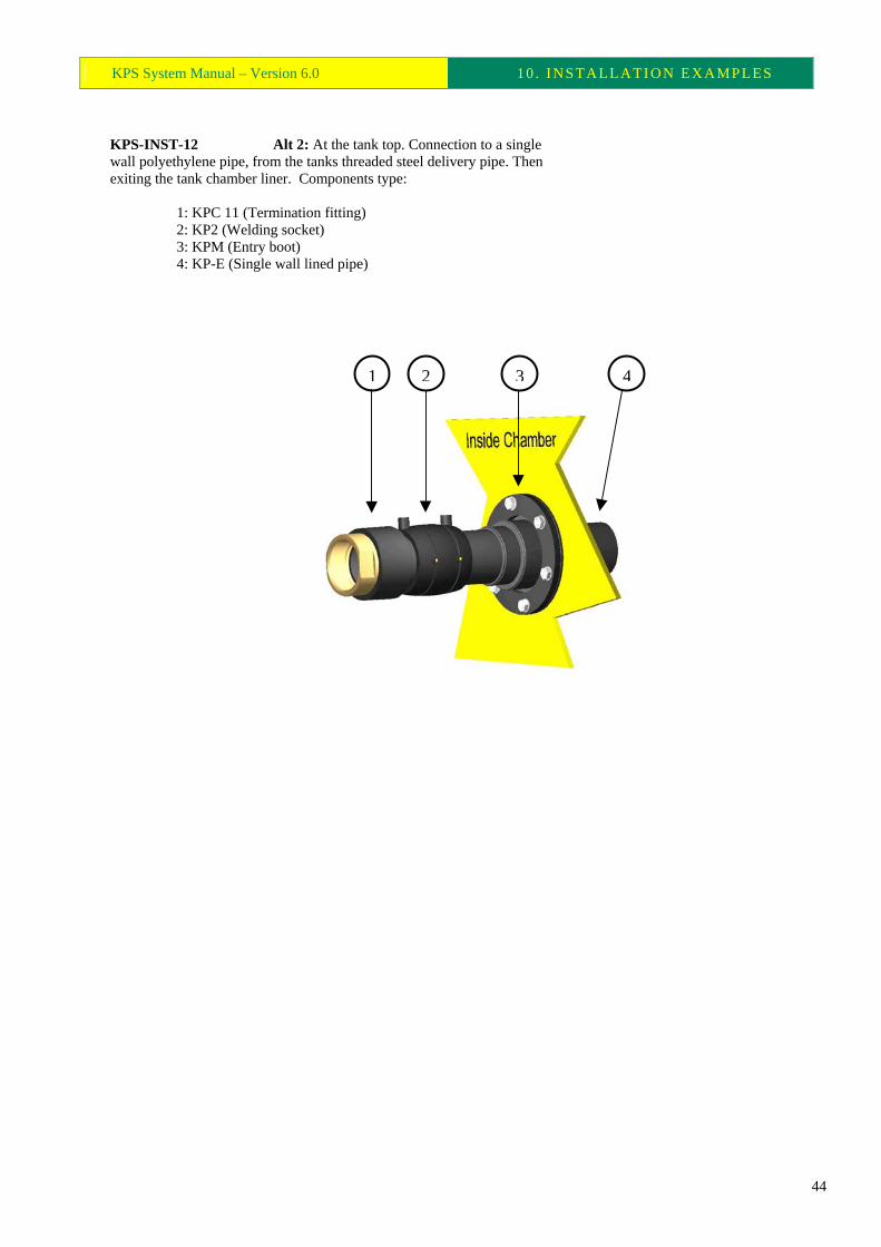
KPS-INST-12 Alt 2: At the tank top. Connection to a single wall polyethylene pipe, from the tanks threaded steel delivery pipe. Then exiting the tank chamber liner. Components type: 1: KPC 11 (Termination fitting) 2: KP2 (Welding socket) 3: KPM (Entry boot) 4: KP-E (Single wall lined pipe)
1 32 4
44

KPS System Manual – Version 6.0 10 . INSTALLATION EXAMPLES
KPS-INST-13 At the tank top. Flanged connection to single wall polyethylene pipework, from the delivery pipe tank flange. Then exiting the tank chamber liner. Components type: 1: KP7 (Gasket) 2: KP5 (Stub flange) 3: KP6 (Steel flange) 4: KP2 (Welding socket) 5: KPM (Entry boot) 6: KP-E (Single Wall Lined Pipe)
1 432 65
45

KPS System Manual – Version 6.0 10 . INSTALLATION EXAMPLES
KPS-INST-14 At the tank top. Flanged connection to Secondary Contained polyethylene pipework from the delivery pipe tank flange. Then exiting the tank chamber liner. Components type: 1: KP7 (Gasket) 2: KP5 (Stub flange) 3: KP6 (Steel flange) 4: KP2 (Welding socket) 5: KPT-SC (Transition fitting) 6: KPM (Entry boot) 7: KP-SC (Secondary Contained Pipe)
1 432 5 6 7
46

KPS System Manual – Version 6.0 10 . INSTALLATION EXAMPLES
KPS-INST-15 At the dispenser end. Entry of the single wall polyethylene pipework into the dispenser sump. Tee off and convert to threaded steel pipe for dispenser entry. Primary polyethylene line to continue and exit the dispenser sump. Components type: 1: KPC 11 (Termination fitting) 2: KP2 (Welding socket) 3: KP8-FCL (Tee connection long leg) 4: KPM (Entry boot) 5: KP-E (Single Wall Lined Pipe)
1
4
3
2
5
47

KPS System Manual – Version 6.0 10 . INSTALLATION EXAMPLES
KPS-INST-16 At the dispenser end. Entry of the single wall polyethylene pipework into the dispenser sump. Turn through 90º into the vertical and connect to threaded steel pipe for entry into the dispenser. Components type: 1: KPC 11 (Termination fitting) 2: KP2 (Welding socket) 3: KP3-FCL (900 bend with long leg) 4: KPM (Entry boot) 5: KP-E (Single Wall Lined Pipe)
14 3 25
48

KPS System Manual – Version 6.0 10 . INSTALLATION EXAMPLES
KPS-INST-18 At the dispenser end. Entry of the Secondary Contained polyethylene pipe into the dispenser sump. Tee off and terminate the secondary containment in the vertical plane. Connect the primary to threaded steel pipe for dispenser entry. Continue the double containment, bridge for monitoring and exit the dispenser sump. Components type: 1: KPC 11 (Termination fitting) 2: KP2 (Welding socket) 3: KP8-FCL (Tee connection long leg) 4: KPT-SC (Transition fitting) 5: KPM (Entry boot) 6: KP-SC (Secondary Contained Lined Pipe)
1
4
3
2
5
6
49
KPS System Manual – Version 6.0 10 . INSTALLATION EXAMPLES
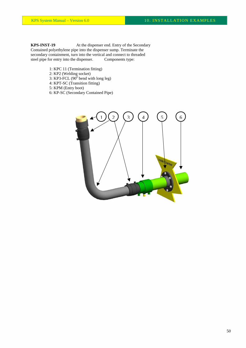
KPS-INST-19 At the dispenser end. Entry of the Secondary Contained polyethylene pipe into the dispenser sump. Terminate the secondary containment, turn into the vertical and connect to threaded steel pipe for entry into the dispenser. Components type: 1: KPC 11 (Termination fitting) 2: KP2 (Welding socket) 3: KP3-FCL (900 bend with long leg) 4: KPT-SC (Transition fitting) 5: KPM (Entry boot) 6: KP-SC (Secondary Contained Pipe)
6541 32
50

KPS System Manual – Version 6.0 10 . INSTALLATION EXAMPLES
Tanks Venting System
KPS-INST-25 Polyethylene vent pipe termination at the vent stack’s location. Protection of any part of the transition fitting from the concrete slab can be achieved by wrapping the area in ‘Denso’ tape. Components type: 1: KPC 11 (Termination fitting) 2: KP2 (Welding socket) 3: KP3-FC (900 bend) 4: KP-E (Single Wall Lined Pipe)
2 3 41
51

KPS System Manual – Version 6.0 10 . INSTALLATION EXAMPLES
General Layouts
KP-INST-30 Example of layout for a suction system (split lines) with 4 tanks, 4 fuel types, 4 dispensers, venting system with stacks and both stage 1b and stage 2 vapour recovery system.
52

KPS System Manual – Version 6.0 10 . INSTALLATION EXAMPLES
KP-INST-35 Example layout for a pressure system with 4 tanks, 4 fuel types, 4 dispensers, venting system with stacks and both stage 1 and stage 2 vapour recovery system.
53

KPS System Manual – Version 6.0 10 . INSTALLATION EXAMPLES
KP-INST-37 Secondary Contained off-set fill line, from the sump at the road tanker delivery point, to the fuel tank top chamber liner. 90º and 45º bends used to permit expansion and contraction.
54

KPS System Manual – Version 6.0 10 . INSTALLATION EXAMPLES
KP-INST-38 Secondary Contained off-set fill line, from the sump at the road tanker delivery point, to the fuel tank top chamber liner. 90º bends used to permit expansion and contraction.
55


![Pressure switch, types KPS 31 - KPS 47 · 220V, 12 W DC PILOT p 120 bar t p bar Type P [bar] KPS 31 6 KPS 33 10 KPS 35 12 KPS 37 27 KPS 39 53 KPS 43 180 KPS 45 180 KPS 47 180 Type](https://static.fdocuments.net/doc/165x107/5f4c47e688839d7ca60d81a7/pressure-switch-types-kps-31-kps-47-220v-12-w-dc-pilot-p-120-bar-t-p-bar-type.jpg)