INSTALLATION INSTRUCTIONS Part No. 81104 MAGNUM …
18
81104 Rev 11/12/20 Page 1 of 18 www.bmracing.com Technical Support (866) 464-6553 INSTALLATION INSTRUCTIONS Part No. 81104 MAGNUM GRIP PRO STICK™ UNIVERSAL SHIFTER w/DUAL MOMENTARY 12V SWITCHES for the automac transmissions listed below, with applicable gate plate (kit includes 3-speed forward-paern gate plate) INTRODUCTION The B&M Magnum Grip Pro Sck™ gated shiſter delivers rock-solid performance, clean design cues, and compact size. Its “one-hand” reverse lockout lever meets NHRA and IHRA safety requirements. A 3-speed forward-paern gate plate is standard. (Gate plates for 2-speed Powerglide, 3-speed reverse-paern, 3-speed off-road, and 4-speed applicaons are available separately, and described in “OPERATION.”) And the two momentary switches allow you to control 12 volt accessories (such as nitrous, roll control, trans-brake, etc.) The shiſter can be mounted directly to the floor, or to a quick- release mount bracket (available separately). This kit includes a neutral safety switch. An oponal backup light switch is available separately. Before starng, take the me to read and understand these instrucons. Also, use the parts list to verify your kit’s contents. In the unlikely event that any parts are missing, please contact B&M Technical Support for replacements. NOTE: Some hardware bags are shared by similar B&M shiſters. While your bag may include extra items that are used on other shiſters, the parts list below shows all the parts required for this shiſter. REQUIRED SUPPLIES • Medium strength thread-locking fluid (Permatex Blue or equivalent) • Nylon-compable epoxy or CA (cyanoacrylate) adhesive APPLICABLE TRANSMISSIONS This shiſter kit includes all cable brackets and selector levers required for use with the following transmissions: This shiſter can be used with the following transmissions with the addional B&M parts shown (sold separately; addional instrucons included): MANUFACTURER TRANSMISSION Chrysler (1966+) and AMC (1972+) A727 / A518 and A904 / A500 Ford C4 / C5 and C6 GM - Turbo-Hydramac TH200, TH250, TH350, and TH400 MFR TRANSMISSION ADDITIONAL B&M PARTS REQUIRED Ford AOD 40496 (cable bracket & selector lever) Ford AODE & 4R70W 40504 (cable bracket & selector lever) Ford E4OD & 4R100 40505 (cable bracket & selector lever) GM - Turbo- Hydramac (fwd paern only) 200-4R & 700R4 / 4L60 80712 (4-speed gate plate) GM - electronic, no PRNDL switch (fwd paern only) 4L60E, 4L65E, 4L70E, 4L75E, 4L80E & 4L85E 80712 (4-speed gate plate) GM - electronic, with PRNDL switch (fwd paern only) 4L60E, 4L65E, 4L70E, 4L75E, 4L80E & 4L85E 80712 (4-speed gate plate) 70499 (cable bracket) GM Powerglide (alumi- num, 1962-73; fwd or reverse paern) 80713 (2-speed gate plate, cable bracket & selector lever)
Transcript of INSTALLATION INSTRUCTIONS Part No. 81104 MAGNUM …

81104Rev 11/12/20
Page 1 of 18www.bmracing.comTechnical Support (866) 464-6553
INSTALLATION INSTRUCTIONSPart No. 81104
MAGNUM GRIP PRO STICK™ UNIVERSAL SHIFTER w/DUAL MOMENTARY 12V SWITCHES
for the automatic transmissions listed below,with applicable gate plate
(kit includes 3-speed forward-pattern gate plate)
INTRODUCTIONThe B&M Magnum Grip Pro Stick™ gated shifter delivers rock-solid performance, clean design cues, and compact size. Its “one-hand” reverse lockout lever meets NHRA and IHRA safety requirements. A 3-speed forward-pattern gate plate is standard. (Gate plates for 2-speed Powerglide, 3-speed reverse-pattern, 3-speed off-road, and 4-speed applications are available separately, and described in “OPERATION.”) And the two momentary switches allow you to control 12 volt accessories (such as nitrous, roll control, trans-brake, etc.)
The shifter can be mounted directly to the floor, or to a quick-release mount bracket (available separately).
This kit includes a neutral safety switch. An optional backup light switch is available separately.
Before starting, take the time to read and understand these instructions.
Also, use the parts list to verify your kit’s contents. In the unlikely event that any parts are missing, please contact B&M Technical Support for replacements.
NOTE: Some hardware bags are shared by similar B&M shifters. While your bag may include extra items that are used on other shifters, the parts list below shows all the parts required for this shifter.
REQUIRED SUPPLIES• Medium strength thread-locking fluid (Permatex Blue
or equivalent)• Nylon-compatible epoxy or CA (cyanoacrylate) adhesive
APPLICABLE TRANSMISSIONSThis shifter kit includes all cable brackets and selector levers required for use with the following transmissions:
This shifter can be used with the following transmissions with the additional B&M parts shown (sold separately; additional instructions included):
MANUFACTURER TRANSMISSION
Chrysler (1966+) and AMC (1972+) A727 / A518 and A904 / A500
Ford C4 / C5 and C6
GM - Turbo-Hydramatic TH200, TH250, TH350, and TH400
MFR TRANSMISSION ADDITIONAL B&M PARTS REQUIRED
Ford AOD 40496 (cable bracket & selector lever)
Ford AODE & 4R70W 40504 (cable bracket & selector lever)
Ford E4OD & 4R100 40505 (cable bracket & selector lever)
GM - Turbo-Hydramatic (fwd pattern only)
200-4R &700R4 / 4L60
80712 (4-speedgate plate)
GM - electronic,no PRNDL switch (fwd pattern only)
4L60E, 4L65E,4L70E, 4L75E,4L80E & 4L85E
80712 (4-speedgate plate)
GM - electronic,with PRNDL switch (fwd pattern only)
4L60E, 4L65E,4L70E, 4L75E,4L80E & 4L85E
80712 (4-speedgate plate) 70499 (cable bracket)
GMPowerglide (alumi-num, 1962-73; fwd or reverse pattern)
80713 (2-speed gate plate, cable bracket & selector lever)
81104Rev 11/12/20
Page 2 of 18www.bmracing.comTechnical Support (866) 464-6553
NOTES• Installation requires better-than-average mechanical
knowledge and skills. If this job is beyond your abilities, seek the services of a qualified technician.
• The shifter mechanism is precision-assembled at our factory. Any modification or disassembly of the shifter will void its warranty, and can cause it to malfunction. Disassemble items only where specified in the instructions.
• Installation of this shifter may require modification or complete removal of your vehicle’s console, depending on the space available in your vehicle.
• If you do not understand any part of these instructions, please call B&M Technical Support at (866) 464-6553 for assistance.
• The shifter cable in this kit is 5 feet long. Different length shifter cables are available separately from B&M, if required.
• The shifter-transmission positions mentioned throughout these instructions apply to 3-speed forward-pattern transmissions (P-R-N-D-2-1). Transmissions with 2 or 4 speeds, or with reverse-pattern manual valve bodies, will alter your shifter-transmission positions accordingly. This kit includes shift pattern labels for forward- and reverse-pattern 2- and 3-speed transmissions, and for forward-pattern 4-speeds.
SAFETY WARNINGS• WORK SAFELY! For maximum safety, perform this installation
on a clean, level surface, with the engine turned off. Chock the wheels to prevent vehicle movement. To avoid bodily injury or vehicle damage, do not begin work until you are confident that the vehicle is safely secured and will not move.
• AVOID SERIOUS INJURY OR DEATH BY CRUSHING! If you have to raise the vehicle to work under it, securely support it on a lift or jack stands. NEVER work under a vehicle that is supported only by jacks!
• WARNING: This B&M performance shifter uses a cable to shift the transmission only; it is NOT intended or designed to operate a locking steering column! If your vehicle has a locking steering column, it must either be a) MODIFIED, to allow the steering column to lock when the key is removed (modification described later); or b) DISABLED, to prevent the steering column from locking if the ignition switch is turned to LOCK while driving (not described in these instructions). If you are not comfortable performing this work, or if you don’t understand this warning, seek the services of a qualified technician for the safe installation of this shifter.
PARTS LIST
INSTALLATION1. Remove the stock shift linkage.
Column Shifters: Remove all rods, levers or cables from the column and the transmission. Place the column shift lever in the PARK position. Remove the pin holding the shift lever in the column and remove the lever assembly. If your vehicle is equipped with a locking steering column, secure the column lock lever in the full up position. (See WARNING re. locking steering columns, above.)
Console Shifters: Remove the shifter mechanism from the console. Disconnect the rod or the cable from the transmission. Remove the cable bracket if equipped. If there
DESCRIPTION QTYSHIFTER ASSEMBLY 1BOLT, 1/4-20 × 1-1/4" 4MICRO-SWITCH 1BRACKET, MICRO-SWITCH 1SCREW, 4-40 × 5/8" 2WASHER, SPLIT LOCK #4 2NUT, HEX 4-40 2SCREW, 10-24 × 3/8" 1CABLE, SHIFTER, SUPER-DUTY 5' 1E-CLIP, 1/4" I.D. 1BOLT, 1/4-20 × 1/2" 1NUT, HEX 1/4-20 6WASHER, SPLIT LOCK 1/4" 5SELECTOR LEVER, CHRYSLER / AMC 1CABLE BRACKET, CHRYSLER / AMC 1SELECTOR LEVER, FORD C4 / C5 and C6 1CABLE BRACKET, FORD C4 / C5 1CABLE BRACKET, FORD C6 1SELECTOR LEVER, GM TH & ELECTRONIC 1CABLE BRKT, GM TH & ELECTRONIC (NO PRNDL SWITCH) 1BOLT, 1/4-20 × 1-1/2" 1BOLT, 5/16-18 × 1" 2BOLT, M8-1.25 × 25 (FOR GM & FORD 4-SPEEDS) 2WASHER, FLAT 5/16" 2SPACER, 7/16" I.D. × 1/4" L 2SWIVEL, CABLE 1JAM NUT, 10-32 (COMES INSTALLED ON CABLE END) 1PIN, COTTER 1/16" × 1" 1WIRE TERMINAL, FEMALE, 1/4", BLUE, 16-14 AWG 2WIRE CONNECTOR, BUTT, RED, 18-22 AWG 4COVER, PRO STICK 1SPACER, NYLON, 1/4" I.D. × 5/16" THK 1SPACER, NYLON, 1/4" I.D. × 3/16" THK 3PIN, QUICK-RELEASE 2DECAL SHEET, SHIFT PATTERN 1HANDLE, REVERSE LOCKOUT LEVER 1SCREW 8-32 × 3/8" 1

81104Rev 11/12/20
Page 3 of 18www.bmracing.comTechnical Support (866) 464-6553
is a cable or linkage from the console shifter or transmission to the steering column lock, it must be secured in the PARK position as described above.
Switch Wires: While removing the stock shift linkage, look for neutral safety and / or backup light switches and wiring. (These mechanisms vary on different vehicles. See the installation section for your vehicle for details.) Label any such wires to simplify installation.
2. Identify the shifter’s switch wires. Use a multimeter to determine which pair of wires goes to each button, and label the wires with tape (“Top” and “Bottom”).
3. Change the gate plate (if applicable). Remove the two screws and three e-clips that retain the gate plate. Replace the gate plate, then reinstall the screws and e-clips.
NOTES:• If you are installing the optional quick-release mount
bracket, follow the bracket’s instructions, then skip to Step 8 below.
• See “OPERATION” to learn how to perform various shift movements before installing the shifter (while the gate plate and selector pin are visible).
4. Locate the shifter in your vehicle. Pull the carpet (if any) away from the floorboard where the shifter will be mounted. If the vehicle has a bench seat, move it to the full forward position. Then place the shifter on the floor, locating it for ease and convenience of operation.
When the shift handle is pulled fully rearward, there must be at least 1" clearance between the handle and the seat when the seat is in the full forward position. Make sure the handle will clear the dash and seat when it is pushed forward and rearward.
When you are satisfied with the position of the shifter, mark the location of the four mount holes on the floor.
5. Drill four 9/32" mount holes through the floor. Put the shifter in place and temporarily hold it with the four 1/4-20 × 1-1/4" bolts.
NOTE: If your vehicle’s floor is too thin to properly support the shifter mechanism when bolted to it, fabricate a sheet metal stiffener to reinforce it.
6. Drill the shifter cable hole.
NOTE: The cable is not installed at this time. It is only shown above for illustration purposes.
Mark the center for the cable hole at least 4-1/2" from the front of the shifter base (see Caution at Step 9), and in line with the shifter’s cable notch. Drill or cut a hole that will provide at least 3/16" clearance around the cable.
7. Return the carpet to its original position (but do not secure it yet). Cut holes in the carpet for the shifter mount holes, and cut a suitable slit for the cable. (Do not use a drill bit to make the holes in the carpet.)
8. Install the micro-switch(es).
NOTE: Installation of the micro-switches is optional on 1969+ Chryslers and AMCs, as the stock neutral safety and backup light switches on the transmission will continue to function normally.
CAUTION: Tighten the fasteners only until the lock washers are squeezed flat. Over-tightening may crack the switch housings.
First assemble the switch and bracket using the two #4-40 × 5/8" screws, lock washers and nuts. Then assemble the bracket to the shifter using the 10-24 × 3/8" screw.
SCREWS
E-CLIPS
NEUTRAL SAFETY SW
ONLY
4-1/2" MIN
81104Rev 11/12/20
Page 4 of 18www.bmracing.comTechnical Support (866) 464-6553
NOTE: If installing the optional backup light switch, use #4-40 × 1-1/4" screws (customer-supplied).
Check switch placement to verify they close when required (neutral safety switch closes only in NEUTRAL and PARK; backup light switch closes in REVERSE). Adjust the switch position on the bracket if necessary.
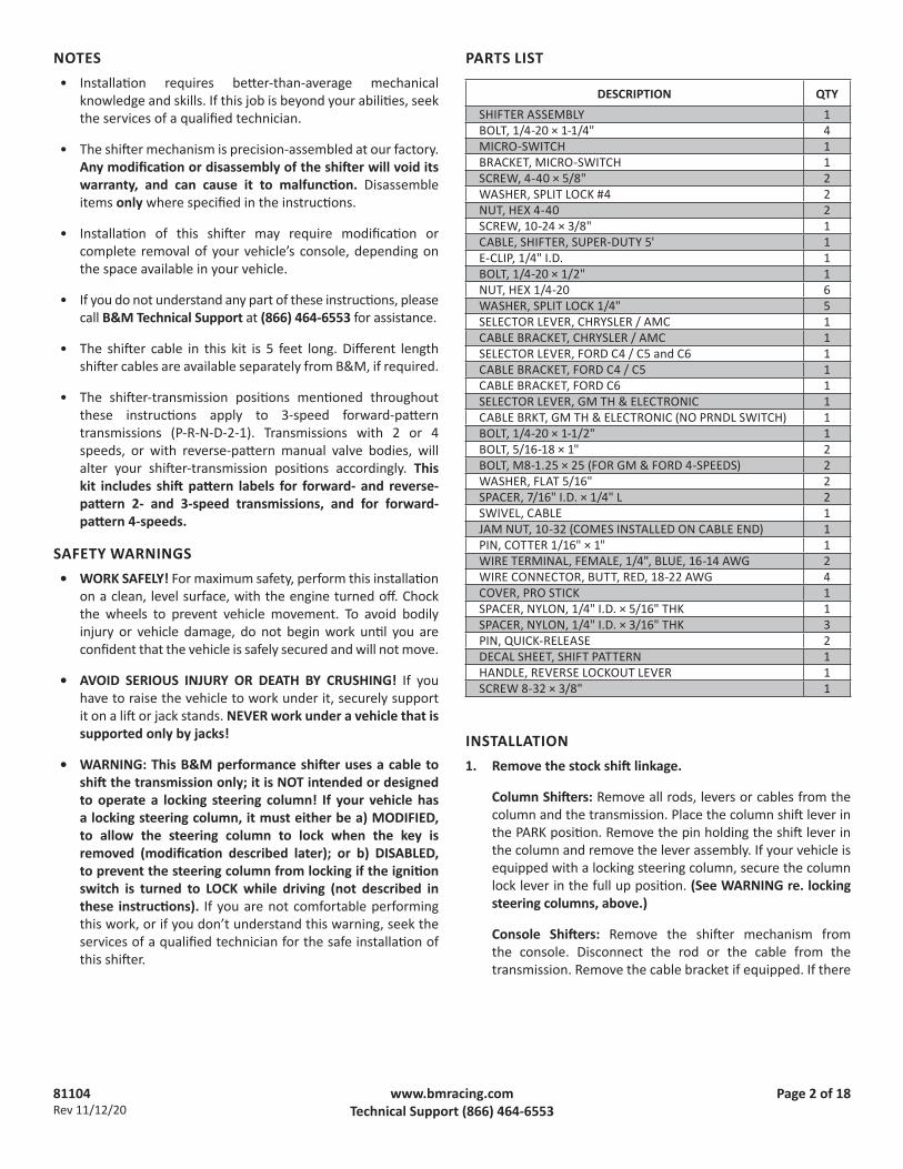
9. Assemble the cable and shifter. Secure the cable eye to the shifter pin with the 1/4" I.D. e-clip. Then secure the cable’s mount tab to the outside surface of the shifter tab with the 1/4-20 × 1/2" bolt and nut (apply medium strength thread-locking fluid to the bolt).
CAUTION: Do not kink the cable anywhere along its length, or it will lock up. The cable should be kept straight for at least 2" after it leaves the brass ferrule at each end.
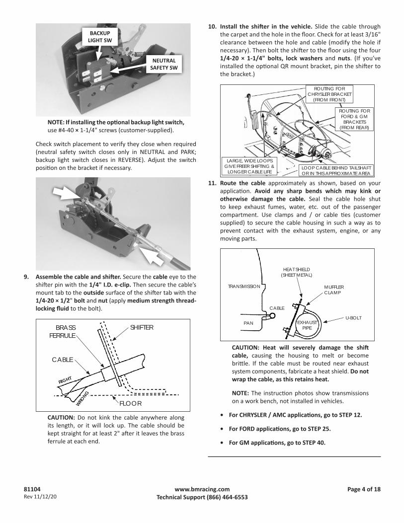
10. Install the shifter in the vehicle. Slide the cable through the carpet and the hole in the floor. Check for at least 3/16" clearance between the hole and cable (modify the hole if necessary). Then bolt the shifter to the floor using the four 1/4-20 × 1-1/4" bolts, lock washers and nuts. (If you’ve installed the optional QR mount bracket, pin the shifter to the bracket.)
11. Route the cable approximately as shown, based on your application. Avoid any sharp bends which may kink or otherwise damage the cable. Seal the cable hole shut to keep exhaust fumes, water, etc. out of the passenger compartment. Use clamps and / or cable ties (customer supplied) to secure the cable housing in such a way as to prevent contact with the exhaust system, engine, or any moving parts.
CAUTION: Heat will severely damage the shift cable, causing the housing to melt or become brittle. If the cable must be routed near exhaust system components, fabricate a heat shield. Do not wrap the cable, as this retains heat.
NOTE: The instruction photos show transmissions on a work bench, not installed in vehicles.
• For CHRYSLER / AMC applications, go to STEP 12.
• For FORD applications, go to STEP 25.
• For GM applications, go to STEP 40.
TRANSMISSION
PAN
CABLE
EXHAUSTPIPE
HEAT SHIELD(SHEET METAL)
MUFFLER CLAMP
U-BOLT
WRONG
RIGHT
CABLE
SHIFTERBRASS FERRULE
FLOOR
LARGE, WIDE LOOPS GIVE FREER SHIFTING &
LONGER CABLE LIFE
ROUTING FOR CHRYSLER BRACKET
(FROM FRONT)
LOOP CABLE BEHIND TAILSHAFT OR IN THIS APPROXIMATE AREA
ROUTING FOR FORD & GM BRACKETS
(FROM REAR)
NEUTRAL SAFETY SW
BACKUP LIGHT SW
81104Rev 11/12/20
Page 5 of 18www.bmracing.comTechnical Support (866) 464-6553
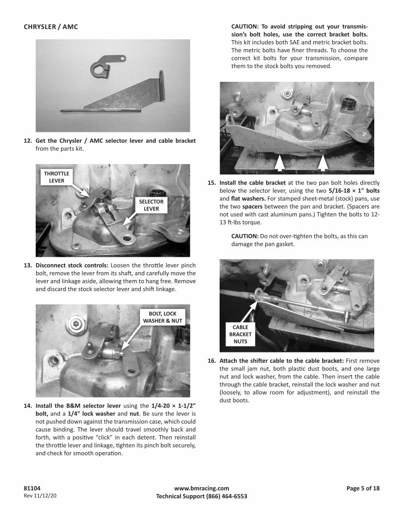
CHRYSLER / AMC
12. Get the Chrysler / AMC selector lever and cable bracket from the parts kit.
13. Disconnect stock controls: Loosen the throttle lever pinch bolt, remove the lever from its shaft, and carefully move the lever and linkage aside, allowing them to hang free. Remove and discard the stock selector lever and shift linkage.
14. Install the B&M selector lever using the 1/4-20 × 1-1/2" bolt, and a 1/4" lock washer and nut. Be sure the lever is not pushed down against the transmission case, which could cause binding. The lever should travel smoothly back and forth, with a positive “click” in each detent. Then reinstall the throttle lever and linkage, tighten its pinch bolt securely, and check for smooth operation.
CAUTION: To avoid stripping out your transmis-sion’s bolt holes, use the correct bracket bolts. This kit includes both SAE and metric bracket bolts. The metric bolts have finer threads. To choose the correct kit bolts for your transmission, compare them to the stock bolts you removed.
15. Install the cable bracket at the two pan bolt holes directly below the selector lever, using the two 5/16-18 × 1" bolts and flat washers. For stamped sheet-metal (stock) pans, use the two spacers between the pan and bracket. (Spacers are not used with cast aluminum pans.) Tighten the bolts to 12-13 ft-lbs torque.
CAUTION: Do not over-tighten the bolts, as this can damage the pan gasket.
16. Attach the shifter cable to the cable bracket: First remove the small jam nut, both plastic dust boots, and one large nut and lock washer, from the cable. Then insert the cable through the cable bracket, reinstall the lock washer and nut (loosely, to allow room for adjustment), and reinstall the dust boots.
THROTTLE LEVER
SELECTOR LEVER
BOLT, LOCK WASHER & NUT
CABLE BRACKET
NUTS
81104Rev 11/12/20
Page 6 of 18www.bmracing.comTechnical Support (866) 464-6553
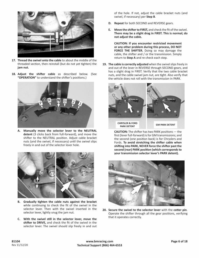
17. Thread the swivel onto the cable to about the middle of the threaded section, then reinstall (but do not yet tighten) the jam nut.
18. Adjust the shifter cable as described below. (See “OPERATION” to understand the shifter’s positions.)
A. Manually move the selector lever to the NEUTRAL detent (3 clicks back from full-forward), and move the shifter to the NEUTRAL position. Adjust cable bracket nuts (and the swivel, if necessary) until the swivel slips freely in and out of the selector lever hole.
B. Gradually tighten the cable nuts against the bracket while continuing to check the fit of the swivel in the selector lever. Then with the swivel inserted in the selector lever, lightly snug the jam nut.
C. With the swivel still in the selector lever, move the shifter to DRIVE, and check the fit of the swivel in the selector lever. The swivel should slip freely in and out
of the hole. If not, adjust the cable bracket nuts (and swivel, if necessary) per Step B.
D. Repeat for both SECOND and REVERSE gears.
E. Move the shifter to FIRST, and check the fit of the swivel. There may be a slight drag in FIRST. This is normal; do not adjust the cable.
CAUTION: If you encounter restricted movement or any other problem during this process, DO NOT FORCE THE SHIFTER. Doing so may damage the cable, the shifter and / or the transmission. Simply return to Step A and re-check each step.
19. The cable is correctly adjusted when the swivel slips freely in and out of the lever in REVERSE through SECOND gears, and has a slight drag in FIRST. Verify that the two cable bracket nuts, and the cable swivel jam nut, are tight. Also verify that the vehicle does not roll with the transmission in PARK.
CAUTION: The shifter has two PARK positions — the first (lever full-forward) is for GM transmissions; and the second (one position back) is for Chryslers and Fords. To avoid stretching the shifter cable when shifting into PARK, NEVER force the shifter past the second (rear) PARK position (which corresponds to your transmission selector lever’s PARK detent).
20. Secure the swivel to the selector lever with the cotter pin. Operate the shifter through all the gear positions, verifying that it operates correctly.
CHRYSLER & FORD PARK DETENT GM PARK DETENT
2 1N DR
P

81104Rev 11/12/20
Page 7 of 18www.bmracing.comTechnical Support (866) 464-6553
21. Check the operation of the throttle linkage again. The linkage must operate smoothly with no binding.
CAUTION: The throttle linkage must be connected and operating on all transmissions using automatic valve bodies, or transmission damage will result.
NEUTRAL SAFETY AND BACKUP LIGHT SWITCHES1966-68 VEHICLES: The stock neutral safety switch will continue
to function normally. Therefore, only the (optional) backup light switch on the shifter is applicable (if used).
22. Reroute the backup light switch wires: Disconnect the battery ground cable. Then disconnect the wires from the stock backup light switch (located on either the steering column, or the console shifter). Route the wires to the B&M shifter.
23. Wire the switch: Strip 1/4" of insulation off the wires and crimp a terminal to each wire, using an appropriate crimping tool.
CAUTION: Failure to use an appropriate tool to crimp the terminals may result in defective, unreliable connections.
Tape or heat-shrink the terminal-wire connections for added protection of the crimps. Connect the backup light wires to the UPPER switch (see Step 8).
24. Verify switch function: Reconnect the battery ground cable. Check the backup light switch by verifying the backup light is on only when the shifter is in REVERSE. If required, adjust the backup light switch as described at Step 8.
1969+ VEHICLES: The stock neutral safety and backup light switches are located on the transmission, and will continue to function normally. Therefore, use of the B&M micro-switches is optional.
Proceed to “Finish Installation,” Step 55.

81104Rev 11/12/20
Page 8 of 18www.bmracing.comTechnical Support (866) 464-6553
FORD
25. Get the Ford selector lever and appropriate cable bracket from the parts kit.
26. Disconnect stock controls: Remove and retain the nut and lock washer holding the throttle lever on its shaft. Carefully remove the throttle lever, and move it and its linkage aside, allowing them to hang free. Remove and discard the stock shift linkage.
CAUTION: Ensure that the oil seal remains in place between the selector and throttle shafts. If the seal comes out, replace it before continuing.
27. If your transmission is equipped with a neutral safety / backup light switch: Remove the two mount bolts and slide the switch off the selector shaft. Cut the wiring harness between the switch and its connector, and discard the switch. (The wires from the connector will be routed to the B&M switches later.)
28. Move the selector lever to NEUTRAL (2 clicks from PARK). If the selector lever points downward, cut it off at the inboard bend, to allow correct positioning of the B&M lever.
29. Install the B&M selector lever using the 1/4-20 × 1-1/2" bolt, lock washer and nut. (See NOTE on next page.) With the selector shaft still in NEUTRAL, align the selector lever perpendicular to the oil pan split-line, then tighten the fasteners.
90°
CUT
THROTTLE LEVER
SELECTOR LEVER
C4 / C5 C6
OIL SEAL
81104Rev 11/12/20
Page 9 of 18www.bmracing.comTechnical Support (866) 464-6553
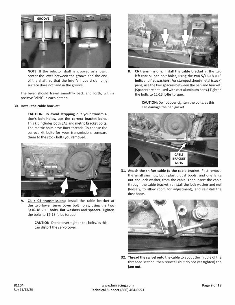
NOTE: If the selector shaft is grooved as shown, center the lever between the groove and the end of the shaft, so that the lever’s inboard clamping surface does not land in the groove.
The lever should travel smoothly back and forth, with a positive “click” in each detent.
30. Install the cable bracket:
CAUTION: To avoid stripping out your transmis-sion’s bolt holes, use the correct bracket bolts. This kit includes both SAE and metric bracket bolts. The metric bolts have finer threads. To choose the correct kit bolts for your transmission, compare them to the stock bolts you removed.
A. C4 / C5 transmissions: Install the cable bracket at the two lower servo cover bolt holes, using the two 5/16-18 × 1" bolts, flat washers and spacers. Tighten the bolts to 12-13 ft-lbs torque.
CAUTION: Do not over-tighten the bolts, as this can distort the servo cover.
B. C6 transmissions: Install the cable bracket at the two left rear oil pan bolt holes, using the two 5/16-18 × 1" bolts and flat washers. For stamped sheet-metal (stock) pans, use the two spacers between the pan and bracket. (Spacers are not used with cast aluminum pans.) Tighten the bolts to 12-13 ft-lbs torque.
CAUTION: Do not over-tighten the bolts, as this can damage the pan gasket.
31. Attach the shifter cable to the cable bracket: First remove the small jam nut, both plastic dust boots, and one large nut and lock washer, from the cable. Then insert the cable through the cable bracket, reinstall the lock washer and nut (loosely, to allow room for adjustment), and reinstall the dust boots.
32. Thread the swivel onto the cable to about the middle of the threaded section, then reinstall (but do not yet tighten) the jam nut.
GROOVE
CABLE BRACKET
NUTS

81104Rev 11/12/20
Page 10 of 18www.bmracing.comTechnical Support (866) 464-6553
33. Adjust the shifter cable as described below. (See “OPERATION” to understand the shifter’s positions.)
A. With the selector lever still in NEUTRAL (2 clicks from PARK) and the shifter in the NEUTRAL position (shown), adjust the cable bracket nuts (and swivel, if necessary) until the swivel slips freely in and out of the selector lever hole.
B. Gradually tighten the cable nuts against the bracket while continuing to check the fit of the swivel in the selector lever. Then with the swivel inserted in the selector lever, lightly snug the jam nut.
C. With the swivel still in the selector lever, move the shifter to DRIVE, and check the fit of the swivel in the selector lever. The swivel should slip freely in and out of the hole. If not, adjust the cable bracket nuts (and swivel, if necessary) per Step B.
D. Repeat for both SECOND and REVERSE gears.
E. Move the shifter to FIRST, and check the fit of the swivel. There may be a slight drag in FIRST. This is normal; do not adjust the cable.
CAUTION: If you encounter restricted movement or any other problem during this process, DO NOT FORCE THE SHIFTER. Doing so may damage the cable, the shifter and / or the transmission. Simply return to Step A and re-check each step.
34. The cable is correctly adjusted when the swivel slips freely in and out of the lever in REVERSE through SECOND gears, and has a slight drag in FIRST. Verify that the two cable bracket nuts, and the cable swivel jam nut, are tight. Also verify that the vehicle does not roll with the transmission in PARK.
CAUTION: The shifter has two PARK positions — the first (lever full-forward) is for GM transmissions; and the second (one position back) is for Chryslers and Fords. To avoid stretching the shifter cable when shifting into PARK, NEVER force the shifter past the second (rear) PARK position (which corresponds to your transmission selector lever’s PARK detent).
35. Secure the swivel to the selector lever with the cotter pin. Operate the shifter through all the gear positions, verifying that it operates correctly.
36. Reinstall the throttle lever, lock washer and nut on the throttle shaft and tighten securely. The throttle lever must operate smoothly with no binding.
CHRYSLER & FORD PARK DETENT GM PARK DETENT
2 1N DR
P

81104Rev 11/12/20
Page 11 of 18www.bmracing.comTechnical Support (866) 464-6553
CAUTION: The throttle linkage must be connected and operating on all transmissions using automatic valve bodies, or transmission damage will result.
NEUTRAL SAFETY AND BACKUP LIGHT SWITCHES37. Reroute the switch wires: Use an applicable electrical
schematic to locate and identify the two neutral safety circuit wires (which prevent cranking unless the transmission is in NEUTRAL or PARK). If desired, do the same for the two backup light wires. Disconnect the battery ground cable. Route the wires to the B&M shifter.
38. Wire the switch(es): Strip 1/4" of insulation off the wires and crimp a terminal to each wire, using an appropriate crimping tool.
CAUTION: Failure to use an appropriate tool to crimp the terminals may result in defective, unreliable connections.
Tape or heat-shrink the terminal-wire connections. Connect the backup light wires to the UPPER switch, and connect the neutral safety wires to the LOWER switch (see Step 8).
39. Verify switch function: Reconnect the battery ground cable, disconnect the coil wire and set the parking brake. Check the neutral safety switch by attempting to crank the engine in each shifter position. The starter must crank only when the shifter is in either PARK or NEUTRAL. Check backup light operation with the shifter in REVERSE. If required, adjust the switches as described at Step 8. After verifying correct switch operation, reconnect the coil wire.
Proceed to “Finish Installation,” Step 55.

81104Rev 11/12/20
Page 12 of 18www.bmracing.comTechnical Support (866) 464-6553
GENERAL MOTORS
40. Get the GM selector lever and cable bracket from the parts kit.
41. Disconnect stock controls: Remove and retain the selector lever nut. Remove and discard the selector lever and shift linkage.
42. Install the B&M selector lever using the stock selector lever nut, and tighten the nut to 23 ft-lbs torque. The lever should travel smoothly back and forth, with a positive “click” in each detent.
43. Check cable bracket fit: Remove the two oil pan bolts to the rear of the selector shaft. Determine which cable bracket holes will be used on your transmission.
CAUTION: To avoid stripping out your transmis-sion’s bolt holes, use the correct bracket bolts. This kit includes both SAE and metric bracket bolts. The metric bolts have finer threads. To choose the correct kit bolts for your transmission, compare them to the stock bolts you removed.
44. Install the cable bracket using either the two 5/16-18 × 1" (SAE), or the two M8-1.25 × 25 (metric) bolts, and two flat washers at the bracket holes that fit your transmission.
A. For stamped sheet-metal (stock) pans, use the two spacers between the pan and bracket.
EXAMPLES
4L60
1 2
SHAFT
TH400
1 2
SHAFT

81104Rev 11/12/20
Page 13 of 18www.bmracing.comTechnical Support (866) 464-6553
B. For cast aluminum pans:• the bracket may need to be trimmed to fit; and• the spacers are not used.
Tighten the bolts to 12-13 ft-lbs torque.
CAUTION: Do not over-tighten the bolts, as this can damage the pan gasket.
45. Attach the shifter cable to the cable bracket: First remove the small jam nut, both plastic dust boots, and one large nut and lock washer, from the cable. Then insert the cable through the cable bracket, reinstall the lock washer and nut (loosely, to allow room for adjustment), and reinstall the dust boots.
46. Thread the swivel onto the cable to about the middle of the threaded section, then reinstall (but do not yet tighten) the jam nut.
47. Adjust the shifter cable as described below. (See “OPERATION” to understand the shifter’s positions.)
A. On the transmission, manually move the selector lever to the NEUTRAL detent (that is, 2 clicks back from full-forward / PARK). Then in the vehicle, move the shifter to the NEUTRAL position. Adjust cable bracket nuts (and the swivel, if necessary) until the swivel slips freely in and out of hole “F” in the selector lever.
B. Gradually tighten the cable nuts against the bracket while continuing to check the fit of the swivel in hole “F” in the selector lever. Then with the swivel inserted in the selector lever, lightly snug the jam nut.
CAUTION: The shifter will not operate properly unless hole “F” in the selector lever is used.
F
EXAMPLE: BRACKET TRIMMED TO FIT ALUMINUM PAN
REMOVE
2 1N DR
P
CABLE BRACKET
NUTS

81104Rev 11/12/20
Page 14 of 18www.bmracing.comTechnical Support (866) 464-6553
C. With the swivel still in the selector lever, move the shifter to DRIVE, and check the fit of the swivel in the selector lever. The swivel should slip freely in and out of hole “F”. If not, adjust the cable bracket nuts (and swivel, if necessary) per Step B.
D. Repeat for both SECOND and REVERSE gears.
E. Move the shifter to FIRST, and check the fit of the swivel. There may be a slight drag in FIRST. This is normal; do not adjust the cable.
CAUTION: If you encounter restricted movement or any other problem during this process, DO NOT FORCE THE SHIFTER. Doing so may damage the cable, the shifter and / or the transmission. Simply return to Step A and re-check each step.
48. The cable is correctly adjusted when the swivel slips freely in and out of the lever in REVERSE through SECOND gears, and has a slight drag in FIRST. Verify that the two cable bracket nuts, and the cable swivel jam nut, are tight. Also verify that the vehicle does not roll with the transmission in PARK.
CAUTION: The shifter has two PARK positions — the first (lever full-forward) is for GM transmissions; and the second (one position back) is for Chryslers and Fords. Once shifter installation is completed, always push the lever FULLY FORWARD to put the transmission into PARK. Otherwise the transmission’s park pawl will not engage, which will allow the vehicle to roll.
49. Secure the swivel to the selector lever with the cotter pin. Operate the shifter through all the gear positions, verifying that it operates correctly.
NEUTRAL SAFETY AND BACKUP LIGHT SWITCHES
50. Determine the type of neutral safety mechanism in your vehicle. It may be either:
• a switch on the stock shifter (whether on the steering column or a console); or
• a mechanical interlock in the steering column that only allows the key to turn to START when the shifter is in PARK or NEUTRAL.
51. Reroute the switch wires: Disconnect the battery ground cable.
A. Neutral safety switch: Use an applicable electrical schematic to locate and identify the two neutral safety circuit wires (which prevent cranking unless the transmission is in NEUTRAL or PARK). Route both wires to the B&M shifter.
B. Mechanical interlock: Use an applicable electrical schematic to locate and identify the wire that runs between the START pole on the ignition switch and the starter relay or solenoid. (This is usually a purple, 10 or 12 AWG wire.) Cut the wire, and route both ends to the B&M shifter.
52. Optional backup light switch: Use an applicable electrical schematic to locate and identify the two backup light wires (usually located on the steering column behind the instrument panel). Route these wires to the B&M shifter.
53. Wire the switches: Strip 1/4" of insulation off the wires and crimp a terminal to each wire, using an appropriate crimping tool.
CAUTION: Failure to use an appropriate tool to crimp the terminals may result in defective, unreliable connections.
Tape or heat-shrink the terminal-wire connections. Connect the backup light wires to the UPPER switch, and connect the neutral safety wires to the LOWER switch (see Step 8).
54. Verify switch function: Reconnect the battery ground cable, disconnect the coil wire and set the parking brake. Check the neutral safety switch by attempting to crank the engine in each shifter position. The starter must crank only when the shifter is in either PARK or NEUTRAL. Check backup light operation with the shifter in REVERSE. If required, adjust the switches as described at Step 8. After verifying correct switch operation, reconnect the coil wire.
GM PARK DETENT CHRYSLER & FORD PARK DETENT

81104Rev 11/12/20
Page 15 of 18www.bmracing.comTechnical Support (866) 464-6553
FINISH INSTALLATION
55. Wire the controlled accessories to the shifter’s pushbuttons using the 4 butt connectors and an appropriate crimping tool. Tape or heat-shrink the connections.
56. If you are not using the optional quick-release bracket, bond the thick spacer over the cover’s front left hole, and bond the three thin spacers over the remaining holes. Allow the joints to dry thoroughly. (If you are using the QR bracket, the cover installs directly over the bracket; no cover spacers are required.)
57. Install the cover. Verify the shifter mechanism is free of any debris or loose hardware. Remove the two screws from the left grip plate, carefully move the plate behind the grip, and lower the cover over the shifter. Then secure the cover to the shifter with the two quick-release pins, and reinstall the grip plate.
58. Install the shift pattern decal and reverse lockout handle. Move the shift lever to NEUTRAL. Select the appropriate shift pattern decal and apply it to the left side of the shifter cover, aligning the “N” with the selector bar in the center of the lever. Then secure the red aluminum reverse lockout handle to the reverse lockout lever with the black 8-32 × 3/8" screw.
59. Fasten the carpet to the vehicle floor.
Congratulations! Your B&M Pro Stick™ shifter is now installed and ready to use.
THICK SPACER
THIN SPACERS

81104Rev 11/12/20
Page 16 of 18www.bmracing.comTechnical Support (866) 464-6553
INSTALLATION CHECKLIST F Locking steering column lever is permanently fastened
in the full up position (Step 1).
F Shifter is convenient to reach and has ample room for driver’s hand throughout its range of motion (Step 4).
F Carpet covers floorboard holes (Step 7).
F Cable is connected to the shifter pin, and cable housing is securely fastened to the shifter base (Step 9).
F Cable hole provides 3/16" clearance minimum, and shifter is securely mounted to floorboard (Step 10).
F Cable is routed clear of exhaust system, engine, and any moving parts (Step 11).
F Selector lever is securely installed on the transmission (Step 14, 29, or 42).
F Cable bracket bolts are tightened to 12-13 ft-lbs torque (Step 15, 30, or 44).
F Shifter is properly adjusted; vehicle does not roll with transmission in PARK; cable boots are installed; cable nuts are tightened; swivel is secured with jam nut and cotter key (Steps 18-20; 33-35; or 47-49).
F The neutral safety switch is connected and properly adjusted to prevent engine start in FORWARD and REVERSE drive gears (Steps 37-39; or 50-54).
F There is no debris in the shifter mechanism and cover is installed (Step 57).
F Reverse lockout handle and shift pattern decal are installed (Step 58).
F Shifter moves freely into and out of all positions, as described in Operation.
CAUTION: If your shifter is not working properly do not attempt to drive your car! Verify you have followed all instructions. If the shifter is broken or defective, return it to your B&M dealer.
OPERATIONLearn how to perform various shift movements before installing the shifter (while the gate plate and selector pin are visible).
See the “PARK NOTE” at the end of this section re. the correct shifter position for putting your transmission in PARK (GM, or Chrysler & Ford).
3-SPEED FORWARD PATTERN GATE PLATE
PARK to FIRST: Pull the trigger, then pull the shift lever all the way back, releasing the trigger when passing through REVERSE.
FIRST to SECOND: Push the lever forward until it stops.
SECOND to THIRD: Pull and hold the trigger, push the lever forward until it stops, then release the trigger and remove pressure from the knob (allowing the spring-loaded selector pin to move to the top of the gate opening).
THIRD or SECOND to FIRST: Pull the lever all the way back.
THIRD to SECOND: Pull and hold the trigger, pull the lever back until it stops, then release the trigger (allowing the selector pin to move to the top of the gate opening).
THIRD to NEUTRAL: Push the lever forward until it stops.
NEUTRAL to REVERSE: Push-and-release the reverse lockout lever, then push the shift lever forward until it stops.
PARK: Pull the trigger, then push the stick forward until it stops. (See the “PARK NOTE” at the end of this section.)

81104Rev 11/12/20
Page 17 of 18www.bmracing.comTechnical Support (866) 464-6553
3-SPEED REVERSE PATTERN GATE PLATE
PARK to FIRST: Pull and hold the trigger, pull the shift lever back until it stops at FIRST, then release the trigger (allowing the spring-loaded selector pin to move to the top of the gate opening).
FIRST to SECOND: Pull the lever back until it stops.
SECOND to THIRD: Pull the trigger, then pull the lever back until it stops.
THIRD to SECOND: Push the lever forward slowly to the “2” position. (The spring-loaded selector pin will move to the top of the gate opening)
THIRD or SECOND to FIRST: Push the lever forward until it stops.
THIRD, SECOND to FIRST to NEUTRAL: Pull and hold the trigger, push the lever forward until it stops, then release the trigger (allowing the spring-loaded selector pin to move to the top of the gate opening).
NEUTRAL to REVERSE: Push-and-release the reverse lockout lever, then push the shift lever forward until it stops.
PARK: Pull the trigger, then push the stick forward until it stops. (See the “PARK NOTE” at the end of this section.)
4-SPEED FORWARD PATTERN GATE PLATE(GM USE ONLY)
PARK to FIRST: Pull the trigger, then pull the shift lever all the way back, releasing the trigger when passing through REVERSE.
FIRST to SECOND: Push the lever forward until it stops.
SECOND to THIRD: Pull the trigger, push the lever forward until it stops, then release the trigger and remove pressure from the knob (allowing the spring-loaded selector pin to move to the top of the gate opening).
THIRD to FOURTH: Push the lever forward until it stops.
FOURTH, THIRD or SECOND to FIRST: Pull the lever all the way back.
FOURTH or THIRD to SECOND: Pull the trigger, pull the lever back until it stops, then release the trigger (allowing the selector pin to move to the top of the gate opening).
DRIVE to NEUTRAL: Pull and hold the trigger, push the lever forward until it stops, then release the trigger (allowing the spring-loaded selector pin to move to the top of the gate opening).
NEUTRAL to REVERSE: Push-and-release the reverse lockout lever, then push the shift lever forward until it stops.
PARK: Pull the trigger, then push the stick forward until it stops. (See the “PARK NOTE” at the end of this section.)

81104Rev 11/12/20
Page 18 of 18www.bmracing.comTechnical Support (866) 464-6553
2-SPEED GATE PLATE
FORWARD PATTERN:
PARK to LOW: Pull the trigger, then pull the shift lever all the way back, releasing the trigger when passing through REVERSE.
LOW to DRIVE: Push the lever forward until it stops.
DRIVE to LOW: Pull the lever all the way back.
LOW or DRIVE to NEUTRAL: Pull and hold the trigger, push the lever forward until it stops, then release the trigger (allowing the spring-loaded selector pin to move to the top of the gate opening).
NEUTRAL to REVERSE: Push-and-release the reverse lockout lever, then push the shift lever forward until it stops.
PARK: Pull the trigger, then push the lever FULLY FORWARD until it stops. (See the “PARK NOTE” at the end of this section.)
REVERSE PATTERN:
PARK to FIRST: Pull and hold the trigger, pull the shift lever back until it stops at FIRST, then release the trigger.
FIRST to SECOND: Pull the lever all the way back.
SECOND to FIRST: Push the lever forward until it stops.
SECOND or FIRST to NEUTRAL: Pull and hold the trigger, push the lever forward until it stops, then release the trigger (allowing the spring-loaded selector pin to move to the top of the gate opening).
NEUTRAL to REVERSE: Push-and-release the reverse lockout lever, then push the shift lever forward until it stops.
PARK: Pull the trigger, then push the lever FULLY FORWARD until it stops. (See the “PARK NOTE” at the end of this section.)
PARK NOTE
The shifter has two PARK positions — the first (lever full-forward) is for GM transmissions; and the second (one position back) is for Chryslers and Fords.
• CHRYSLER & FORD: To avoid stretching the shifter cable, NEVER force the shifter past the rearmost PARK position, which corresponds to your transmission selector lever’s PARK detent.
• GM: Always push the shifter lever FULLY FORWARD to put the transmission into PARK. Otherwise the transmission’s park pawl will not engage, which will allow the vehicle to roll.
KEEP THESE INSTRUCTIONS FOR FUTURE REFERENCEB&M Performance & Off-Road maintains a highly-trained technical service department to answer your technical questions, provide additional product information and offer various recommendations.
B&M TECHNICAL SUPPORT: (866) 464-6553
CHRYSLER & FORD PARK DETENT GM PARK DETENT