Home condo th for rent in zip code 77056 houston tx -august 17th 2011
© 2014 5151 San Felipe St., Suite 500, Houston, TX 77056
www.daikincomfort.com
ATTENTION INSTALLING PERSONNEL:Prior to installation, thoroughly familiarize yourself with thisInstallation Manual. Observe all safety warnings. During in-stallation or repair, caution is to be observed.
It is your responsibility to install the product safely and toeducate the customer on its safe use.
RECOGNIZE THIS SYMBOL AS A SAFETY PRECAUTION.
These installation instructions cover the outdoor installation ofsingle package heating and cooling units. See the SpecificationSheet applicable to your model for information regardingaccessories.
*NOTE: Please contact your distributor or our website for theapplicable Specification Sheet referred to in this manual.
Index
Replacement Parts ................................................................ 2
Safety Instructions ................................................................ 2
General Information ............................................................. 2
Unit Location ........................................................................ 3
Clearances ............................................................................ 4
Roof Curb Post-Installation Checks ....................................... 5
Roof Top Duct Connections ................................................... 5
Rigging Details ...................................................................... 5
Electrical Wiring .................................................................... 7
Circulating Air and Filters ...................................................... 9
Condensate Drain Connection .............................................. 9
Startup, Adjustments, and Checks ..................................... 10
Air flow Adjustments .......................................................... 11
Motor Sheave Adjustments ................................................ 12
Heat Pump Operation ......................................................... 14
Maintenance ...................................................................... 15
Troubleshooting.................................................................. 15
Appendix A Blower Performance Data ................................ 17
Belt Drive - Standard Down Shot ................................... 17
Belt Drive - Standard Horizontal .................................... 18
Belt Drive - High Static Down Shot ................................. 19
Belt Drive - High Static Horizontal .................................. 20
Appendix B Electrical Data .................................................. 21
Appendix C Unit Dimensions ............................................... 22
DCC/DCH SERIESLIGHT COMMERCIAL PACKAGED HEATING AND COOLING UNIT7.5 to 12.5 TON
Our continuing commitment to quality products may mean a change in specifications without notice.
INSTALLATION INSTRUCTIONS
IOD-1002D12/2014

2
REPLACEMENT PARTS
ORDERING PARTS
When reporting shortages or damages, or ordering repairparts, give the complete unit model and serial numbers asstamped on the unit’s nameplate.
Replacement parts for this appliance are available throughyour contractor or local distributor. For the location of yournearest distributor, consult the white business pages, theyellow page section of the local telephone book or contact:
CONSUMER AFFAIRSDAIKIN NORTH AMERICA LLC
7401 SECURITY WAYHOUSTON, TEXAS 77040
855-770-5678
SAFETY INSTRUCTIONS
TO THE INSTALLER
Before installing this unit, please read this manual to familiarizeyourself on the specific items which must be adhered to,including maximum external static pressure to unit, airtemperature rise, minimum or maximum CFM and motorspeed connections.
Keep this literature in a safe place for future reference.
THIS PRODUCT CONTAINS OR PRODUCES A CHEMICAL OR CHEMICALS WHICH MAY CAUSE SERIOUS ILLNESS OR DEATH AND WHICH ARE KNOWN TO THE STATE OF CALIFORNIA TO CAUSE CANCER, BIRTH DEFECTS OR OTHER REPRODUCTIVE HARM.
WARNING
TO AVOID PROPERTY DAMAGE, PERSONAL INJURY OR DEATH, DO NOT USE THIS UNIT IF ANY PART HAS BEEN UNDER WATER. IMMEDIATELY CALL A QUALIFIED SERVICE TECHNICIAN TO INSPECT THE FURNACE AND TO REPLACE ANY PART OF THE CONTROL SYSTEM AND ANY GAS CONTROL HAVING BEEN UNDER WATER.
WARNING
THIS UNIT MUST NOT BE USED AS A “CONSTRUCTION HEATER” DURING THE FINISHING PHASES OF CONSTRUCTION ON A NEW STRUCTURE. THIS TYPE OF USE MAY RESULT IN PREMATURE FAILURE OF THE UNIT DUE TO EXTREMELY LOW RETURN AIR TEMPERATURES AND EXPOSURE TO CORROSIVE OR VERY DIRTY ATMOSPHERES.
WARNING
HIGH VOLTAGE! DISCONNECT ALL POWER BEFORE SERVICING OR INSTALLING THIS UNIT. MULTIPLE POWER SOURCES MAY BE PRESENT. FAILURE TO DO SO MAY CAUSE PROPERTY DAMAGE, PERSONAL INJURY OR DEATH.
WARNING
WARNINGTO PREVENT THE RISK OF PROPERTY DAMAGE, PERSONAL INJURY, OR DEATH,DO NOT STORE COMBUSTIBLE MATERIALS OR USE GASOLINE OR OTHERFLAMMABLE LIQUIDS OR VAPORS IN THE VICINITY OF THIS APPLIANCE.
WARNING
HIGH VOLTAGE! INSTALLATION AND REPAIR OF THIS UNIT SHOULD BE PERFORMED ONLY BY INDIVIDUALS MEETING(AT A MINIMUM) THE REQUIREMENTS OF AN “ENTRY LEVEL TECHNICIAN” AS SPECIFIED BY THE AIR CONDITIONING, HEATING AND REFRIGERATION INSTITUTE (AHRI). ATTEMPTING TO INSTALL OR REPAIR THIS UNIT WITHOUT SUCH BACKGROUND MAY RESULT IN PRODUCT DAMAGE, PERSONAL INJURY OR DEATH.
GENERAL INFORMATION
WARNING
TO PREVENT PROPERTY DAMAGE, PERSONAL INJURY OR DEATH, DUE TO FIRE,EXPLOSIONS, SMOKE, SOOT, CONDENSATION, ELECTRIC SHOCK OR CARBONMONOXIDE, THIS UNIT MUST BE PROPERLY INSTALLED, REPAIRED, OPERATED,AND MAINTAINED.
This unit is approved for outdoor installation ONLY. Rated perfor-mance is achieved after 72 hours of operation. Rated performanceis delivered at the specified airflow. See outdoor unit specifica-tion sheet for split system models or product specification sheetfor packaged and light commercial models. Specification sheetscan be found at www.daikincomfort.com for Daikin brand prod-ucts. Within either website, please select the residential or com-mercial products menu and then select the submenu for the typeof product to be installed, such as air conditioners or heat pumps,to access a list of product pages that each contain links to thatmodel’s specification sheet.
To assure that your unit operates safely and efficiently, it must beinstalled, operated, and maintained in accordance with these in-stallation and operating instructions, all local building codes andordinances.
SHEET METAL PARTS, SCREWS, CLIPS AND SIMILAR ITEMS INHERENTLY HAVE SHARP EDGES, AND IT IS NECESSARY THAT THE INSTALLER AND SERVICE PERSONNEL EXERCISE CAUTION.
CAUTION

3
EPA REGULATIONS
IMPORTANT: THE UNITED STATES ENVIRONMENTAL PROTECTION AGENCY (EPA)HAS ISSUED VARIOUS REGULATIONS REGARDING THE INTRODUCTION AND DISPOSAL
OF REFRIGERANTS IN THIS UNIT. FAILURE TO FOLLOW THESE REGULATIONS MAY
HARM THE ENVIRONMENT AND CAN LEAD TO THE IMPOSITION OF SUBSTANTIAL
FINES. BECAUSE REGULATIONS MAY VARY DUE TO PASSAGE OF NEW LAWS, WE
SUGGEST A CERTIFIED TECHNICIAN PERFORM ANY WORK DONE ON THIS UNIT.SHOULD YOU HAVE ANY QUESTIONS PLEASE CONTACT THE LOCAL OFFICE OF THE
EPA.
NATIONAL CODES
This product is designed and manufactured to permit installationin accordance with National Codes. It is the installer’s responsibil-ity to install the product in accordance with National Codes and/or prevailing local codes and regulations.
The heating and cooling capacities of the unit should be greaterthan or equal to the design heating and cooling loads of the areato be conditioned. The loads should be calculated by an approvedmethod or in accordance with ASHRAE Guide or Manual J - LoadCalculations published by the Air Conditioning Contractors ofAmerica.
Obtain from:
American National Standards Institute1430 Broadway
New York, NY 10018System design and installation should also, where applicable, fol-low information presented in accepted industry guides such as theASHRAE Handbooks. The manufacturer assumes no responsibilityfor equipment installed in violation of any code or regulation. Themechanical installation of the packaged roof top units consists ofmaking final connections between the unit and building services;supply and return duct connections; and drain connections (if re-quired). The internal systems of the unit are completely factory-installed and tested prior to shipment.
Units are generally installed on a steel roof mounting curb assem-bly which has been shipped to the job site for installation on theroof structure prior to the arrival of the unit. The model numbershown on the unit’s identification plate identifies the various com-ponents of the unit such as refrigeration tonnage, heating inputand voltage.
Carefully inspect the unit for damage. Any bolts or screws whichmay have loosened in transit must be re-tightened. In the event ofdamage, the receiver should:
1. Make notation on delivery receipt of any visible damageto shipment or container.
2. Notify carrier promptly and request an inspection.3. In case of concealed damage, carrier should be notified as
soon as possible-preferably within 5 days.4. File the claim with the following supporting documents:a. Original Bill of Lading, certified copy, or indemnity bond.b. Original paid freight bill or indemnity in lieu thereof.c. Original invoice or certified copy thereof, showing trade
and other discounts or reductions.
d. Copy of the inspection report issued by carrierrepresentative at the time damage is reported to thecarrier. The carrier is responsible for making promptinspection of damage and for a thorough investigation ofeach claim. The distributor or manufacturer will notaccept claims from dealers for transportation damage.
NOTE: When inspecting the unit for transportation damage, removeall packaging materials. Recycle or dispose of the packagingmaterial according to local codes.
PRE-INSTALLATION CHECKS
Carefully read all instructions for the installation prior to installingunit. Ensure each step or procedure is understood and any specialconsiderations are taken into account before starting installation.Assemble all tools, hardware and supplies needed to complete theinstallation. Some items may need to be purchased locally.
UNIT LOCATION
TO PREVENT POSSIBLE EQUIPMENT DAMAGE, PROPERTY DAMAGE, PERSONAL INJURY OR DEATH, THE FOLLOWING BULLET POINTS MUST BE OBSERVED WHEN INSTALLING THE UNIT.
WARNING
IMPORTANT NOTE: Remove wood shipping rails and metal ship-ping brace (if applicable) prior to installation of the unit on a roofcurb.
ALL INSTALLATIONS:
IMPORTANT NOTE: Unit should be energized 24 hours prior tocompressor start up to ensure crankcase heater has suffi-ciently warmed the compressors. Compressor damage mayoccur if this step is not followed.
NOTE: Appliance is shipped from factory for vertical ductapplication.Proper installation of the unit ensures trouble-free operation. Im-proper installation can result in problems ranging from noisyoperation to property or equipment damages, dangerous condi-tions that could result in injury or personal property damage andcould void the warranty. Give this booklet to the user and explainit’s provisions. The user should retain these instructions for futurereference.
• For proper operation and condensate drainage, the unitmust be mounted level.
• To avoid possible illness or death of the building occupants,do NOT locate outside air intake device (economizer,manual fresh air intake, motorized fresh air intake) tooclose to an exhaust outlet, gas vent termination, orplumbing vent outlet. For specific distances required,consult local codes.
• Allow minimum clearances from the enclosure for fireprotection, proper operation, and service access (see UnitClearances). These clearances must be permanentlymaintained.

4
• When the unit is heating, the temperature of the returnair entering the unit must be between 50°F and 100°F.
GROUND LEVEL INSTALLATIONS ONLY:
• When the unit is installed on the ground adjacent to thebuilding, a level concrete (or equal) base is recommended.Prepare a base that is 3” larger than the package unitfootprint and a minimum of 3” thick.
• The base should also be located where no runoff of waterfrom higher ground can collect in the unit.
ROOF TOP INSTALLATIONS ONLY:
• To avoid possible property damage or personal injury, theroof must have sufficient structural strength to carry theweight of the unit(s) and snow or water loads as requiredby local codes. Consult a structural engineer to determinethe weight capabilities of the roof.
• The unit may be installed directly on wood floors or onClass A, Class B, or Class C roof covering material.
• To avoid possible personal injury, a safe, flat surface forservice personnel should be provided.
• As indicated on the unit’s data plate, a minimum clearanceof 36” to any combustible material is required on the accessside of the unit. All combustible materials must be keptout of this area.
• Adequate clearances from the unit to any adjacent publicwalkways, adjacent buildings, building openings oropenable windows must be maintained in accordance withNational Codes.
UNIT PRECAUTIONS
• Do not stand or walk on the unit.• Do not drill holes anywhere in panels or in the base frame
of the unit (except where indicated). Unit access panelsprovide structural support.
• Do not remove any access panels until unit has beeninstalled on roof curb or field supplied structure.
• Do not roll unit across finished roof without prior approvalof owner or architect.
• Do not skid or slide on any surface as this may damageunit base. The unit must be stored on a flat, level surface.Protect the condenser coil because it is easily damaged.
ROOF CURB INSTALLATIONS ONLY:Curb installations must comply with local codes and should be donein accordance with the established guidelines of the National Roof-ing Contractors Association.
Proper unit installation requires that the roof curb be firmly andpermanently attached to the roof structure. Check for adequatefastening method prior to setting the unit on the curb.
Full perimeter roof curbs are available from the factory and areshipped unassembled. Field assembly, squaring, leveling andmounting on the roof structure are the responsibility of the in-stalling contractor. All required hardware necessary for the as-sembly of the sheet metal curb is included in the curb accessory.
TO PREVENT POSSIBLE EQUIPMENT DAMAGE, PROPERTY DAMAGE, PERSONAL INJURY OR DEATH, THE FOLLOWING BULLET POINTS MUST BE OBSERVED WHEN INSTALLING THE UNIT.
WARNING
• Sufficient structural support must be determined prior tolocating and mounting the curb and package unit.
• Ductwork must be constructed using industry guidelines.The duct work must be placed into the roof curb beforemounting the package unit. Our full perimeter curbsinclude duct connection frames to be assembled with thecurb. Cantilevered type curbs are not available from thefactory.
• Curb insulation, cant strips, flashing and general roofingmaterial are furnished by the contractor.
The curbs must be supported on parallel sides by roof members.The roof members must not penetrate supply and return duct open-ing areas as damage to the unit might occur.
NOTE: The unit and curb accessories are designed to allow verticalduct installation before unit placement. Duct installation after unitplacement is not recommended.
ALL CURBS LOOK SIMILAR. TO AVOID INCORRECT CURB POSITIONING, CHECK JOB PLANS CAREFULLY AND VERIFY MARKINGS ON CURB ASSEMBLY. INSTRUCTIONS MAY VARY IN CURB STYLES AND SUPERSEDES INFORMATION SHOWN.
CAUTION
See the manual shipped with the roof curb for assembly and in-stallation instructions.
CLEARANCES
36” MIN.
36”*
36”*
UNIT CLEARANCES
*In situations that have multiple units, a 48” minimum clearance isrequired between the condenser coils.

5
Adequate clearance around the unit should be kept for safety, ser-vice, maintenance, and proper unit operation. A total clearance of75” on the main control panel side of the unit is recommended tofacilitate possible fan shaft, coil, electric heat and gas furnace re-moval. A clearance of 48” is recommended on all other sides ofthe unit to facilitate possible compressor removal, to allow serviceaccess and to insure proper ventilation and condenser airflow. Theunit must not be installed beneath any obstruction. The unit shouldbe installed remote from all building exhausts to inhibit ingestionof exhaust air into the unit fresh air intake.
INSULATEDPANELS
Roof Curb Installation
ROOF CURB POST-INSTALLATION CHECKSAfter installation, check the top of the curb, duct connection frameand duct flanges to make sure gasket has been applied properly.Gasket should be firmly applied to the top of the curb perimeter,duct flanges and any exposed duct connection frame. If gasket isloose, re-apply using strong weather resistant adhesive.
PROTRUSION
Inspect curb to ensure that none of the utility services (electric)routed through the curb protrude above the curb.
IF PROTRUSIONS EXIST, DO NO ATTEMPT TO SET UNIT ON CURB.
CAUTION
ROOF TOP DUCT CONNECTIONS
Install all duct connections on the unit before placing the unit onrooftop.
HORIZONTAL DISCHARGE
Refer to IOD-7006 included in the literature pack for installing hori-zontal duct covers.
Flexible duct connectors between the unit and ducts are recom-mended. Insulate and weatherproof all external ductwork andjoints as required and in accordance with local codes.
RETURN
SUPPLY13 7/8”
28 3/8” 7 3/8”
12 5/8” 5 7/8”
6 1/4”
36 3/8”
REMOVE COVERS
HORIZONTAL DISCHARGE DUCT CONNECTIONS
RIGGING DETAILS
WARNING
TO PREVENT PROPERTY DAMAGE, THE UNIT SHOULD REMAIN IN AN UPRIGHTPOSITION DURING ALL RIGGING AND MOVING OPERATIONS. TO FACILITATELIFTING AND MOVING WHEN A CRANE IS USED, PLACE THE UNIT IN ANADEQUATE CABLE SLING.
DO NOT LIFT UNITS TWO AT A TIME. PROVISIONS FOR FORKS HAVE BEEN INCLUDED IN THE UNIT BASE FRAME. MINIMUM FORK LENGTH IS 48” TO PREVENT DAMAGE TO THE UNIT.
CAUTION
Provisions for forks have been included in the unit base frame. Noother fork locations are approved.

6
WARNING
TO PREVENT POSSIBLE EQUIPMENT DAMAGE, PROPERTY DAMAGE, PERSONALINJURY OR DEATH, THE FOLLOWING BULLET POINTS MUST BE OBSERVEDWHEN INSTALLING THE UNIT.
• Unit must be lifted by the four lifting holes located at thebase frame corners.
• Lifting cables should be attached to the unit with shackles.• The distance between the crane hook and the top of the
unit must not be less than 60”.• Two spreader bars must span over the unit to prevent
damage to the cabinet by the lift cables. Spreader barsmust be of sufficient length so that cables do not come incontact with the unit during transport. Remove woodstruts mounted beneath unit base frame before setting uniton roof curb. These struts are intended to protect unitbase frame from fork lift damage. Removal is accomplishedby extracting the sheet metal retainers and pulling thestruts through the base of the unit. Refer to rigging labelon the unit.
• Your unit may be equipped with a steel shipping bracelocated underneath the unit (under compressors). Ifinstalling on a roof curb, the brace MUST be removed.Follow the following instructions for removal.
WHEN UNIT IS SUSPENDED, BOARDS AND SHIPPING BRACE WILL DROP WHEN SCREWS ARE REMOVED. TO PREVENT PERSONAL INJURY, STAND CLEAR.REMOVE FORK HOLE BRACKETS, BOARDS AND SHIPPING BRACE FROM BOTTOMOF UNIT BEFORE PLACING UNIT ONTO CURB.
CAUTION
Before installing this unit on a roof curb:1. Remove wooden struts per installation instructions. These
are the struts that are located in the fork holes and areused to protect the unit from damage while lifting withforks.
2. Locate and remove the twelve (12) screws that attach theshipping brace to the side rails. There will be six (6) screwson each side of the unit and they are in a diagonal pattern.See following figure.
3. Lift unit per the “Rigging Details” section of the installationinstructions, observing all warnings and cautions. Lift theunit high enough off the ground to reach under and graspthe shipping brace.
4. Rotate the brace by tapping the ends until the brace fallsfree from the unit.
5. Dispose of the brace appropriately.Important: If using bottom discharge with roof curb, ductworkshould be attached to the curb prior to installing the unit. Ductworkdimensions are shown in Roof Curb Installation Instructions.
Refer to the Roof Curb Installation Instructions for proper curb in-stallation. Curbing must be installed in compliance with the Na-tional Roofing Contractors Association Manual.
Lower unit carefully onto roof mounting curb. While rigging unit,center of gravity will cause condenser end to be lower than supplyair end.

7
To assist in determining rigging requirements, unit weights areshown as follows:
CG
XB D
Y
A C
RETURN
SUPPLY
EVAPORATOR COILCOMPRESSOR 1
COMPRESSOR 2
CORNER & CENTER OF GRAVITY LOCATIONS
090 102 120 150
Corner Weight - A 313 310 310 420
Corner Weight - B 248 263 263 335
Corner Weight - C 250 258 258 290
Corner Weight - D 199 219 219 230
Unit Shipping Weight 1085 1125 1125 1300
Unit Operating Weight 1010 1050 1050 1275
X (Inches) 44 45 45 41
Y (Inches) 27 28 28 27.5
DATADCC Weights (lbs)
090 102/120 150
Corner Weight - A 285 345 435
Corner Weight - B 285 325 345
Corner Weight - C 285 320 300
Corner Weight - D 285 300 240
Unit Shipping Weight 1175 1310 1350
Unit Operating Weight 1135 1285 1325
X (Inches) 48 48 41
Y (Inches) 30 30 27.5
DATADCH Weights (lbs)
NOTE: These weights are without accessories installed.
TO PREVENT SEVERE DAMAGE TO THE BOTTOM OF THE UNIT, DO NOT FORK LIFT UNIT AFTER WOOD STRUTS HAVE BEEN REMOVED.
CAUTION
Bring condenser end of unit into alignment with the curb. Withcondenser end of the unit resting on curb member and using curbas a fulcrum, lower opposite end of the unit until entire unit isseated on the curb. When a rectangular cantilever curb is used,care should be taken to center the unit. Check for proper align-ment and orientation of supply and return openings with duct.
RIGGING REMOVAL
TO PREVENT DAMAGE TO THE UNIT, DO NOT ALLOW CRANE HOOKS AND SPREADER BARS TO REST ON THE ROOF OF THE UNIT.
CAUTION
Remove spreader bars, lifting cables and other rigging equipment.
ELECTRICAL WIRING
HIGH VOLTAGE! DISCONNECT ALL POWER BEFORE SERVICING OR INSTALLING THIS UNIT. MULTIPLE POWER SOURCES MAY BE PRESENT. FAILURE TO DO SO MAY CAUSE PROPERTY DAMAGE, PERSONAL INJURY OR DEATH.
WARNING
HIGH VOLTAGE! TO AVOID PERSONAL INJURY OR DEATH DUE TO ELECTRICAL SHOCK, DO NOT TAMPER WITH FACTORY WIRING. THE INTERNAL POWER AND CONTROL WIRING OF THESE UNITS ARE FACTORY-INSTALLED AND HAVE BEEN THOROUGHLY TESTED PRIOR TO SHIPMENT. CONTACT YOUR LOCAL REPRESENTATIVE IF ASSISTANCE IS REQUIRED.
WARNING
TO PREVENT DAMAGE TO THE WIRING, PROTECT WIRING FROM SHARP EDGES. FOLLOW NATIONAL ELECTRICAL CODE AND ALL LOCAL CODES AND ORDINANCES. DO NOT ROUTE WIRES THROUGH REMOVABLE ACCESS PANELS.
CAUTION
CONDUIT AND FITTINGS MUST BE WEATHER-TIGHT TO PREVENT WATER ENTRY INTO THE BUILDING.
CAUTION
For unit protection, use a fuse or HACR circuit breaker that is inexcess of the circuit ampacity, but less than or equal to the maxi-mum overcurrent protection device. DO NOT EXCEED THE MAXI-MUM OVERCURRENT DEVICE SIZE SHOWN ON UNIT DATA PLATE.
All line voltage connections must be made through weatherprooffittings. All exterior power supply and ground wiring must be inapproved weatherproof conduit.

8
The main power supply wiring to the unit and low voltage wiringto accessory controls must be done in accordance with these in-structions, the latest edition of the National Electrical Code (ANSI/NFPA 70), and all local codes and ordinances. All field wiring shallconform with the temperature limitations for Type T wire (63°F/35°C rise).
The main power supply shall be three-phase, three wire. The unitis factory wired for the voltage shown on the unit’s data plate.
NOTE: If supply voltage is 208V, all leads on primary of transformerTRANS1 must be moved from the 230V to the 208V tap.
Main power wiring should be sized for the minimum wire ampacityshown on the unit’s data plate. Size wires in accordance with theampacity tables in Article 310 of the National Electrical Code. Iflong wires are required, it may be necessary to increase the wiresize to prevent excessive voltage drop. Wires should be sized for amaximum of 3% voltage drop.
CAUTION
TO AVOID PROPERTY DAMAGE OR PERSONAL INJURY DUE TO FIRE, USEONLY COPPER CONDUCTORS.
LABEL ALL WIRES PRIOR TO DISCONNECTION WHEN SERVICING CONTROLS. WIRING ERRORS CAN CAUSE IMPROPER AND DANGEROUS OPERATION. VERIFY PROPER OPERATION AFTER SERVICING.
CAUTION
NOTE: A weather-tight disconnect switch, properly sized for theunit total load, must be field or factory installed. An external fieldsupplied disconnect may be mounted on the exterior panel.
Ensure the data plate is not covered by the field-supplied disconnectswitch.
• Some disconnect switches are not fused. Protect the powerleads at the point of distribution in accordance with theunit’s data plate.
• The unit must be electrically grounded in accordance withlocal codes or, in the absence of local codes, with the latestedition of the National Electrical Code (ANSI-NFPA 70). Aground lug is provided for this purpose. Size groundingconductor in accordance with Table 250-95 of the NationalElectrical Code. Do not use the ground lug for connectinga neutral conductor.
• Connect power wiring to the Single Point Power block. Thisterminal block is located within the main control box.
POWERWIRING
THERMOSTATWIRING
NCC
OM
NO
POWER AND LOW VOLTAGE BLOCK LOCATIONS
FAILURE OF UNIT DUE TO OPERATION ON IMPROPER LINE VOLTAGE OR WITH EXCESSIVE PHASE UNBALANCE CONSTITUTES PRODUCT ABUSE AND WILL VOID YOUR WARRANTY AND MAY CAUSE SEVERE DAMAGE TO THE UNIT ELECTRICAL COMPONENTS.
WARNING
Areas Without Convenience Outlet
It is recommended that an independent 115V power source bebrought to the vicinity of the roof top unit for portable lights andtools used by the service mechanic.
NOTE: Refer to local codes for requirements. These outlets canalso be factory installed.
UNITS INSTALLED ON ROOF TOPS
Main power and low voltage wiring may enter the unit throughthe side or through the roof curb. Install conduit connectors at thedesired entrance locations. External connectors must be weather-proof. All holes in the unit base must be sealed (including thosearound conduit nuts) to prevent water leakage into building. Allrequired conduit and fittings are to be field supplied.
Supply voltage to roof top unit must not vary by more than 10% ofthe value indicated on the unit’s data plate. Phase voltage unbal-ance must not exceed 2%. Contact your local power company forcorrection of improper voltage or phase unbalance.

9
LOW VOLTAGE ENTRANCE
DIMPLES MARK DRILL LOCATIONS
HIGH VOLTAGE ENTRANCE
10 3/16”
26 ½”
ELECTRICAL ENTRANCE LOCATIONS
Unit is equipped with Single Point Power Block and Low VoltageBlock.
LOW VOLTAGE CONTROL WIRING
1. A 24V thermostat must be installed for unit operation. Itmay be purchased with the unit or field -supplied.Thermostats may be programmable or electromechanicalas required.
2. Locate thermostat or remote sensor in the conditionedspace where it will sense average temperature. Do notlocate the device where it may be directly exposed tosupply air, sunlight or other sources of heat. Followinstallation instructions packaged with the thermostat.
3. Use #18 AWG wire for 24V control wiring runs notexceeding 75 feet. Use #16 AWG wire for 24V control wiringruns not exceeding 125 feet. Use #14 AWG wire for 24Vcontrol wiring runs not exceeding 200 feet. Low voltagewiring may be National Electrical Code (NEC) Class 2 wherepermitted by local codes.
4. Route thermostat wires from sub-base terminals to theunit. Control wiring should enter through the duct panel(dimple marks entrance location). Connect thermostat andany accessory wiring to low voltage terminal block TB1 inthe main control box.
NOTE: Field-supplied conduit may need to be installed dependingon unit/curb configuration. Use #18 AWG solid conductor wirewhenever connecting thermostat wires to terminals on sub-base.DO NOT use larger than #18 AWG wire. A transition to #18 AWGwire may be required before entering thermostat sub-base.
NOTE: Refer to unit wiring diagrams for thermostat hookups.
CIRCULATING AIR AND FILTERS
DUCTWORK
The supply duct from the unit through a wall may be installed with-out clearance. However, minimum unit clearances must be main-tained (see “Clearances” section). The supply duct should be pro-vided with an access panel large enough to inspect the air cham-ber downstream of the heat exchanger. A cover should be tightlyattached to prevent air leaks.
Ductwork dimensions are shown in the roof curb installationmanual.
If desired, supply and return duct connections to the unit may bemade with flexible connections to reduce possible unit operatingsound transmission.
CONDENSATE DRAIN CONNECTION
CONDENSATE DRAIN CONNECTION
A 3/4” female NPT drain connection is supplied on the end of theunit and bottom of the drain pan for condensate piping. An exter-nal trap must be installed for proper condensate drainage.
DRAINCONNECTION
UNIT 2" MINIMUM
FLEXIBLETUBING-HOSEOR PIPE
3" MINIMUM
A POSITIVE LIQUIDSEAL IS REQUIRED
Drain Connection
Install condensate drain trap as shown. Use 3/4” drain line andfittings or larger. Do not operate without trap.
HORIZONTAL DRAIN
Drainage of condensate directly onto the roof may be acceptable;refer to local code. It is recommended that a small drip pad of ei-ther stone, mortar, wood or metal be provided to prevent any pos-sible damage to the roof.
CLEANING
Due to the fact that drain pans in any air conditioning unitwill have some moisture in them, algae and fungus willgrow due to airborne bacteria and spores. Periodic clean-ing is necessary to prevent this build-up from plugging thedrain.

10
STARTUP, ADJUSTMENTS, AND CHECKS
HIGH VOLTAGE!
OND THE FRAME OF THIS UNIT TO THE BUILDING ELECTRICAL GROUND BY USE OF THE GROUNDING TERMINAL PROVIDED OR OTHER ACCEPTABLE MEANS. DISCONNECT ALL POWER BEFORE SERVICING OR INSTALLING THIS UNIT.
TO AVOID PERSONAL INJURY OR DEATH DUE TO ELECTRICAL SHOCK, B
WARNING
PRE-STARTUP INSTRUCTIONS - GENERAL
TO PREVENT PROPERTY DAMAGE OR PERSONAL INJURY, DO NOT START THE UNIT UNTIL ALL NECESSARY PRE-CHECKS AND TESTS HAVE BEEN PERFORMED.
CAUTION
Prior to the beginning of Startup, Adjustments, and Checks proce-dures, the following steps should be completed in the building.
Prior to the beginning of Starup, Adjustments, and checksproceudres, the following steps should be completed in thebuilding.
\MOVING MACHINERY HAZARD!TO PREVENT POSSIBLE PERSONAL INJURY OR DEATH, DISCONNECT POWER TO THE UNIT AND PADLOCK IN THE “OFF” POSITION BEFORE SERVICNG FANS.
WARNING
HEATING STARTUP
On new installations, or if a major component has been replaced,the operation of the unit must be checked.
Check unit operation as outlined in the following instructions. Ifany sparking, odors, or unusual sounds are encountered, shut offelectrical power and recheck for wiring errors, or obstructions inor near the blower motors. Duct covers must be removed beforeoperating unit.
The Startup, Adjustments, and Checks procedure provides a step-by-step sequence which, if followed, will assure the proper startupof the equipment in the minimum amount of time. Air balancingof duct system is not considered part of this procedure. However,it is an important phase of any air conditioning system startup andshould be performed upon completion of the Startup, Adjustments,and Checks procedure. The Startup, Adjustments, and Checks pro-cedure at outside ambients below 55°F should be limited to a readi-ness check of the refrigeration system with the required final checkand calibration left to be completed when the outside ambientrises above 55°F.
TEMPORARY HEATING OR COOLING
If the unit is to be used for temporary heating or cooling, a “Startup,Adjustments, and Checks” must first be performed in accordancewith this manual. Failure to comply with this requirement will void
the warranty. After the machines are used for temporary heatingor cooling, inspect the coils, fans, and motors for unacceptablelevels of construction dust and dirt and install new filters.
CONTRACTOR RESPONSIBILITY
The installing contractor must be certain that:
• All supply and return air ductwork is in place, properlysealed, and corresponds with installation instructions.
• All thermostats are mounted and wired in accordancewith installation instructions.
• All electric power, all gas, hot water or steam lineconnections, and the condensate drain installation havebeen made to each unit on the job. These main supplylines must be functional and capable of operating all unitssimultaneously.
• Air filters are in place.
ROOF CURB INSTALLATION CHECK
Inspect the roof curb for correct installation. The unit and curbassembly should be level. Inspect the flashing of the roof mount-ing curb to the roof, especially at the corners, for good workman-ship. Also check for leaks around gaskets. Note any deficiencies ina separate report and forward to the contractor.
OBSTRUCTIONS, FAN CLEARANCE AND WIRING
Remove any extraneous construction and shipping materials thatmay be found during this procedure. Rotate all fans manually tocheck for proper clearances and that they rotate freely. Check forbolts and screws that may have jarred loose during shipment tothe job site. Retighten if necessary. Re-tighten all electrical con-nections.
FIELD DUCT CONNECTIONS
Verify that all duct connections are tight and that there is no airbypass between supply and return.
FILTER SECTION CHECK
Remove filter section access panels and check that filters are prop-erly installed. Note airflow arrows on filter frames.
PRE-STARTUP PRECAUTIONS
It is important to your safety that the unit has been properlygrounded during installation. Check ground lug connection in maincontrol box for tightness prior to closing circuit breaker or discon-nect switch. Verify that supply voltage on line side of disconnectagrees with voltage on unit identification plate and is within theutilization voltage range as indicated in Appendix B Electrical Data.
System Voltage - That nominal voltage value assigned to a circuitor system for the purpose of designating its voltage class.
Nameplate Voltage - That voltage assigned to a piece of equip-ment for the purpose of designating its voltage class and for thepurpose of defining the minimum and maximum voltage at whichthe equipment will operate.

11
Utilization Voltage - The voltage of the line terminals of the equip-ment at which the equipment must give fully satisfactory perfor-mance. Once it is established that supply voltage will be maintainedwithin the utilization range under all system conditions, check andcalculate if an unbalanced condition exists between phases. Calcu-late percent voltage unbalance as follows:
Three Phase Models Only
3) PERCENT VOLTAGE UNBALANCE
2) MAXIMUM VOLTAGE DEVIATIONSFROM AVERAGE VOLTAGE
1) AVERAGE VOLTAGE
HOW TO USE THE FORMULA:EXAMPLE: With voltage of 220, 216, and 2131) Average Voltage = 220+216+213=649 / 3 = 2162) Maximum Voltage Deviations from Average Voltage = 220 - 216 = 4
3) Percent Voltage Unbalance = 100 x = = 1.8%
Percent voltage unbalance MUST NOT exceed 2%.
4216
400216
= 100 X
CONTROL VOLTAGE CHECK
With disconnect switch in the open “OFF” position, disconnect bluewire from low voltage transformer TRANS1. Close the disconnectswitch to energize TRANS1 control transformer. Check primary andsecondary (24V) of control transformer TRANS1.
AIR FLOW ADJUSTMENTS
NOTE: For 2 Speed Models, airflow adjustments must be made onhigh speed, i.e., 2nd stage cooling or in heat mode.The drive on the supply fan is typically set in the middle of theRPM range. The drive motor sheave pitch diameter is field adjust-able for the required airflow. Refer to the following “DriveAdjustments” section.
When the final adjustments are complete, the current draw of themotor should be checked and compared to the full load currentrating of the motor. The amperage must not exceed the servicefactor stamped on the motor nameplate. The total airflow mustnot be less than that required for operation of the electric heatersor the furnace.
If an economizer is installed, check the unit operating balance withthe economizer at full outside air and at minimum outside air. Uponcompletion of the air flow balancing, we recommend replacing thevariable pitched motor sheave with a properly-sized fixed sheave.A matching fixed sheave will provide longer belt and bearing lifeand vibration free operation. Initially, it is best to have a variablepitched motor sheave for the purpose of airflow balancing, butonce the balance has been achieved, fixed sheaves maintain align-ment and minimize vibration more effectively. For direct drive units,move green wire for fan.
NOTE: On “non-two speed models” (two-speed models have a “V”in the eleventh character of the model number), never run CFMbelow 300 CFM per ton. Evaporator freezing or poor unit perfor-mance is possible.
EVAPORATOR FAN ROTATION CHECK (THREE PHASE MODELS ONLY)Check that fan rotates counter-clockwise when viewed from thedrive side of unit and in accordance with rotation arrow shown onblower housing. If it does not, reverse the two incoming powercables. In this case, repeat bearing check.
Do not attempt to change load side wiring. Internal wiring assuresall motors and compressors will rotate in correct direction onceevaporator fan motor rotation check has been made.
ELECTRICAL INPUT CHECK
Make preliminary check of evaporator fan ampere draw and verifythat motor nameplate amps are not exceeded. A final check ofamp draw should be made upon completion of air balancing ofthe duct system (see Appendix B).
SET EVAPORATOR FAN RPMActual RPM’s must be set and verified with a tachometer or strobelight. Refer to Appendices A and B for basic unit fan RPM. Referalso to “Airflow” section of this manual. With disconnect switchopen, disconnect thermostat wires from terminals Y and W. Thiswill prevent heating and mechanical cooling from coming on. Placea jumper wire across terminals R and G at TB1 terminal block. Closedisconnect switch; evaporator fan motor will operate so RPM canbe checked.
START-UP PROCEDURE AND CHECKLIST FOR 2 SPEED MODELS:
Models with a V in the 11th position of the model number.
For 2 speed models, the indoor blower will operate on low speedwhen in “Fan Only” mode or while in first stage “Cooling” mode.Unit will operate on high speed in “Heating” mode and while insecond stage “Cooling” mode.
The start-up procedure is the same as for “Air Conditioning Start-up Procedure” with the understanding that in Step 6, the indoorblower will run at low speed (~1175 motor rpm) and in Step 7, theindoor blower will operate at high speed (~1775 motor rpm).
NOTE: While in the Cooling Mode, to prevent frost from formingon the evaporator while the unit is operating in outdoortemperatures of 65°F or lower, it is recommended that a lowambient kit (LAKT-**) is used. This is strongly recommended for 2Speed models due to the lower airflow while in the first stagecooling. To further protect the compressor from damage duringlow ambient conditions, a Freezestat Kit (FSK01) can be added thatturns the compressor off when the evaporator temperature dropstoo low.
BELT DRIVE MODELS ONLY
The drive on the supply fan is typically set in the middle of theRPM range. The drive motor sheave pitch diameter is field adjust-able for the required airflow. Refer to “Motor Sheave Adjustmens”section.

12
Upon completion of the air flow balancing, we recommend replac-ing the variable pitched motor sheave with a properly-sized fixedsheave. A matching fixed sheave will provide longer belt and bear-ing life and vibration free operation. Initially, it is best to have avariable pitched motor sheave for the purpose of airflow balanc-ing, but once the balance has been achieved, fixed sheaves main-tain alignment and minimize vibration more effectively. For directdrive units, move fan speed wire.
BEARING CHECK
Prior to energizing any fans, check and make sure that all setscrewsare tight so that bearings are properly secured to shafts.
For heat pump units, the airflow must be adjusted so that the airtemperature rise falls within the ranges given stated on Data Plate(see Appendix A - Blower Performance).
TENSION AND ALIGNMENT ADJUSTMENT
Correct belt tension is very important to the life of your belt. Tooloose a belt will shorten its life; too tight, premature motor andbearing failure will occur. Check you belt drive for adequate “run-in” belt tension by measuring the force required to deflect the beltat the midpoint of the span length. Belt tension force can be mea-sured using a belt tension gauge, available through most belt drivemanufacturers.
SPAN LENGTH t*DEFLECTION
FORCE
h
C
dH
D
*Apply force to the center of the span.
t = Span length, inchesC = Center distance, inchesD = Larger sheave diameter, inchesd = Smaller sheave diameter, inchesh = Deflection height, inches
DRIVE BELT TENSION ADJUSTMENT
BELT DRIVE Used New
7.5 Ton 2.6 to 3.6 3.75 +/- 0.5 4.0 +/- 0.5 9/32 +/- 1/16
8.5 Ton 2.6 to 3.6 3.75 +/- 0.5 4.0 +/- 0.5 9/32 +/- 1/16
10 Ton 3.0 to 4.0 3.75 +/- 0.5 4.0 +/- 0.5 9/32 +/- 1/16
12.5 Ton 2.6 to 3.6 3.75 +/- 0.5 4.0 +/- 0.5 9/32 +/- 1/16
A, AX Standard
MODELDEFLECTION
(in)
DEFLECTIONFORCE (lbs)
SHEAVEDIAMETE
R (in)
TYPE
RECOMMENDED POUNDS OF FORCE PER BELT
When new V-belts are installed on a drive, the initial tension willdrop rapidly during the first few hours of use. Check tension fre-quently during the first 24 hours of operation. Subsequentretentioning should fall between the minimum and maximum force.To determine the deflection distance from a normal position, usea straightedge or stretch a cord from sheave to sheave to use as areference line. On multiple belt drives, an adjacent undeflectedbelt can be used as a reference.
MOTOR SHEAVE ADJUSTMENTS
VL, VM & 2VP VARIABLE PITCH KEY TYPE MOTOR SHEAVES
The driving and driven motor sheaves should be in alignment witheach other and the shafts parallel.
VL & VM SHEAVES ADJUSTMENT
1. Loosen set screw “B” using a 5/32" Allen key.2. Making half or full turns from closed position, adjust sheave
pitch diameter for desired speed. DO NOT OPEN MORETHAN FIVE FULL TURNS.
3. Tighten set screw “B” securely over flat.4. Carefully put on belts and adjust belt tension. DO NOT
FORCE BELTS OVER GROOVES.5. Ensure all keys are in place and the set screws tight before
starting drive. Recheck set screws and belt tension after24 hours service.
NOTE: Future adjustments should be made by loosening the belttension and increasing or decreasing the pitch diameter of thesheave by half or full turns as required. Readjust belt tension beforestarting drive.

13
C
B
VL & VM
NOTE: Do not operate sheave with flange projecting beyond thehub end.
REFRIGERATION SYSTEM CHECKS
Ensure the hold-down bolts on the compressor are secure and havenot vibrated loose during shipment. Check that vibration grom-mets have been installed. Visually check all piping and clamps. Theentire refrigeration system has been factory charged and tested,making it unnecessary to field charge. Factory charges are shownon the unit nameplate.
AIR CONDITIONING START-UP PROCEDURE
Begin with power turned off at all disconnects.
1. Turn thermostat system switch to “Cool,” and fan switchto “Auto” and turn temperature setting as high as it willgo.
2. Inspect all registers and set them to the normal openposition.
3. Turn on the electrical supply at the disconnect.
4. Turn the fan switch to the “ON” position. The blower shouldoperate after a 7-second delay.
5. Turn the fan switch to “Auto” position. The blower shouldstop after a 65 second delay.
6. Slowly lower the cooling temperature until first stage COOL(LOW COOL) starts. The blower, both fans, and first stagecompressor should now be operating. Allow the unit torun 10 minutes, make sure cool air is being supplied bythe unit.
7. Lower the cooling temperature further until second stageCOOL (HIGH COOL) starts. The blower, both fans, and bothcompressors should now be operating. Allow the unit torun 10 minutes, make sure cool air is being supplied bythe unit.
8. Turn the temperature setting to the highest position,stopping the unit. The indoor blower will continue to runfor 65 seconds.
9. Turn the thermostat system switch to “OFF” and disconnectall power when servicing the unit.
HIGH VOLTAGE! DISCONNECT ALL POWER BEFORE SERVICING OR INSTALLING THIS UNIT. MULTIPLE POWER SOURCES MAY BE PRESENT. FAILURE TO DO SO MAY CAUSE PROPERTY DAMAGE, PERSONAL INJURY OR DEATH.
WARNING
HEAT PUMP START-UP PROCEDURE
10. Check the cooling mode for the heat pump in the samemanner as above. The reversing valve is energized whenthe thermostat is placed in the cooling position. A clickingsound should be noticeable from the reversing valve. Bylowering the temperature setting to call for cooling, thecontractor is energized. The compressor, blower and fanshould then be running. After the cooling mode is checkedout, turn the thermostat system switch to “OFF”.
11. Turn the thermostat system switch to “HEAT” and fanswitch to “AUTO”.
12. Slowly raise the heating temperature setting. When theheating first stage makes contact, stop raising thetemperature setting.. The compressor, blower and fanshould now be running with the reversing valve in the de-energized (heating) position. After giving the unit time tosettle out, make sure the unit is supplying heated air.
13. If the outdoor ambient is above 80°F, the unit may trip onits high pressure cut out when on heating. The compressorshould stop. The heating cycle must be thoroughlychecked, so postpone the test to another day whenconditions are more suitable but-DO NOT FAIL TO TEST.If the outdoor ambient is low and the unit operatesproperly on the heating cycle, you may check the pressurecutout operation by blocking off the indoor return air untilthe unit trips.
14. If unit operates properly in the heating cycle, raise thetemperature setting until the heating second stage makescontact. Supplemental resistance heat, if installed shouldnow come on. Make sure it operates properly.NOTE: If outdoor thermostats are installed the outdoorambient must be below the set point of these thermostatsfor the heaters to operate. It may be necessary to jumperthese thermostats to check heater operation if outdoorambient is mild.
15. For thermostats with emergency heat switch, return to step11. The emergency heat switch is located at the bottom ofthe thermostat. Move the switch to emergency heat. Theheat pump will stop, the blower will continue to run, allheaters will come on and the thermostat emergency heatlight will come on.
16. If checking the unit in the wintertime, when the outdoorcoil is cold enough to actuate the defrost control, observeat least one defrost cycle to make sure the unit defrostscompletely.
14
FINAL SYSTEM CHECKS
1. Check to see if all supply and return air grilles are adjustedand the air distribution system is balanced for the bestcompromise between heating and cooling.
2. Check for air leaks in the ductwork. See Sections onAir Flow Adjustments.
3. Make sure the unit is free of “rattles”, and the tubing inthe unit is free from excessive vibration. Also make suretubes or lines are not rubbing against each other or sheetmetal surfaces or edges. If so, correct the trouble.
4. Set the thermostat at the appropriate setting for coolingand heating or automatic change over for normal use.
5. Be sure the Owner is instructed on the unit operation, filter,servicing, correct thermostat operation, etc.
REFRIGERATION PERFORMANCE CHECK
Check that compressor RLA corresponds to values shown in Ap-pendix B. RLA draw can be much lower than values listed at lowload conditions and low ambient condensing temperatures. Val-ues in Appendix B can slightly exceed at high load conditions andhigh ambient condensing temperatures.
HEAT PUMP OPERATION
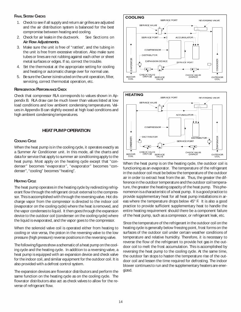
COOLING CYCLE
When the heat pump is in the cooling cycle, it operates exactly asa Summer Air Conditioner unit. In this mode, all the charts anddata for service that apply to summer air conditioning apply to theheat pump. Most apply on the heating cycle except that “con-denser” becomes “evaporator”, “evaporator” becomes “con-denser”, “cooling” becomes “heating”.
HEATING CYCLE
The heat pump operates in the heating cycle by redirecting refrig-erant flow through the refrigerant circuit external to the compres-sor. This is accomplished with through the reversing valve. Hot dis-charge vapor from the compressor is directed to the indoor coil(evaporator on the cooling cycle) where the heat is removed, andthe vapor condenses to liquid. It then goes through the expansiondevice to the outdoor coil (condenser on the cooling cycle) wherethe liquid is evaporated, and the vapor goes to the compressor.
When the solenoid valve coil is operated either from heating tocooling or vice versa, the piston in the reversing valve to the lowpressure (high pressure) reverse positions in the reversing valve.
The following figures show a schematic of a heat pump on the cool-ing cycle and the heating cycle. In addition to a reversing valve, aheat pump is equipped with an expansion device and check valvefor the indoor coil, and similar equipment for the outdoor coil. It isalso provided with a defrost control system.
The expansion devices are flowrator distributors and perform thesame function on the heating cycle as on the cooling cycle. Theflowrator distributors also act as check valves to allow for the re-verse of refrigerant flow.
When the heat pump is on the heating cycle, the outdoor coil isfunctioning as an evaporator. The temperature of the refrigerantin the outdoor coil must be below the temperature of the outdoorair in order to extract heat from the air. Thus, the greater the dif-ference in the outdoor temperature and the outdoor coil tempera-ture, the greater the heating capacity of the heat pump. This phe-nomenon is a characteristic of a heat pump. It is a good practice toprovide supplementary heat for all heat pump installations in ar-eas where the temperature drops below 45° F. It is also a goodpractice to provide sufficient supplementary heat to handle theentire heating requirement should there be a component failureof the heat pump, such as a compressor, or refrigerant leak, etc.
Since the temperature of the refrigerant in the outdoor coil on theheating cycle is generally below freezing point, frost forms on thesurfaces of the outdoor coil under certain weather conditions oftemperature and relative humidity. Therefore, it is necessary toreverse the flow of the refrigerant to provide hot gas in the out-door coil to melt the frost accumulation. This is accomplished byreversing the heat pump to the cooling cycle. At the same time,the outdoor fan stops to hasten the temperature rise of the out-door coil and lessen the time required for defrosting. The indoorblower continues to run and the supplementary heaters are ener-gized.

15
DEFROST CONTROL
NOTE: DCH models have one stage of mechanical heating. The de-frost accumulation period will start when either first or second stagedefrost thermostat closes. Defrost termination occurs when boththermostats open or the 10 minute cycle has completed.
During operation the power to the circuit board is controlled by atemperature sensor, which is clamped to a feeder tube enteringthe outdoor coil. Defrost timing periods of 30,60 and 90 minutesmay be selected by connecting the circuit board jumper to 30, 60and 90 respectively. Accumulation of time for the timing periodselected starts when the sensor closes (approximately 31° F), andwhen the wall thermostat calls for heat. At the end of the timingperiod, the unit’s defrost cycle will be initiated provided the sen-sor remains closed. When the sensor opens (approximately 75° F),the defrost cycle is terminated and the timing period is reset. If thedefrost cycle is not terminated due to the sensor temperature, aten minute override interrupts the unit’s defrost period.
MAINTENANCE
HIGH VOLTAGE! DISCONNECT ALL POWER BEFORE SERVICING OR INSTALLING THIS UNIT. MULTIPLE POWER SOURCES MAY BE PRESENT. FAILURE TO DO SO MAY CAUSE PROPERTY DAMAGE, PERSONAL INJURY OR DEATH.
WARNING
TO PREVENT PERSONAL INJURY OR DEATH DUE TO IMPROPER INSTALLATION, ADJUSTMENT, ALTERATION, SERVICE OR MAINTENANCE, REFER TO THIS MANUAL. FOR ADDITIONAL ASSISTANCE OR INFORMATION, CONSULT A QUALIFIED INSTALLER, SERVICE AGENCY OR THE GAS SUPPLIER.
WARNING
SHEET METAL PARTS, SCREWS, CLIPS AND SIMILAR ITEMS INHERENTLY HAVE SHARP EDGES, AND IT IS NECESSARY THAT THE INSTALLER AND SERVICE PERSONNEL EXERCISE CAUTION.
CAUTION
The Self Contained Packaged Air Conditioner and Heat Pump shouldoperate for many years without excessive service calls if the unit isinstalled properly. However it is recommended that the homeownerinspect the unit before a seasonal start up. The coils should befree of debris so adequate airflow is achieved. The return and sup-ply registers should be free of any obstructions. The filters shouldbe cleaned or replaced. These few steps will help to keep the prod-uct up time to a maximum. The Service section that follows shouldhelp in identifying problems if the unit does not operate properly.
FILTERS
CAUTION
TO PREVENT PROPERTY DAMAGE DUE TO FIRE AND LOSS OFEQUIPMENT EFFICIENCY OR EQUIPMENT DAMAGE DUE TO DUST AND LINTBUILD UP ON INTERNAL PARTS, NEVER OPERATE UNIT WITHOUT AN AIRFILTER INSTALLED IN THE RETURN AIR SYSTEM.
Every application may require a different frequency of replacementof dirty filters. Filters must be replaced at least every three (3)months during operating seasons.
Dirty filters are the most common cause of inadequate heating orcooling performance. Filter inspection should be made at leastevery two months; more often if necessary because of local condi-tions and usage.
Dirty throwaway filters should be discarded and replaced with anew, clean filter.
Disposable return air filters are supplied with this unit. See theunit Specification Sheet or Technical Manual for the correct sizeand part number. To remove the filters, remove the filter accesspanel on return side of the unit.
CABINET FINISH MAINTENANCE
Use a fine grade automotive wax on the cabinet finish to maintainthe finish’s original high luster. This is especially important in in-stallations with extended periods of direct sunlight.
CLEAN OUTSIDE COIL (QUALIFIED SERVICER ONLY)The coil with the outside air flowing over it should be inspectedannually and cleaned as frequently as necessary to keep the finnedareas free of lint, hair and debris.
LUBRICATION
The fan shaft bearings , the 1 to 2 HP supply fan motors, the con-denser fan motors and compressors are permanently lubricated.
FUNCTIONAL PARTS
Refer to the unit Parts Catalog for a list of functional parts. Partsare available from your distributor.
TROUBLESHOOTING
THE FOLLOWING INFORMATION IS FOR USE BY QUALIFIED SERVICEAGENCY ONLY: OTHERS SHOULD NOT ATTEMPT TO SERVICE THISEQUIPMENT.
Common Causes of Unsatisfactory Operation of Heat Pump on theHeating Cycle.
INADEQUATE AIR VOLUME THROUGH INDOOR COIL
When a heat pump is in the heating cycle, the indoor coil is func-tioning as a condenser. The return air filter must always be clean,and sufficient air volume must pass through the indoor coil to pre-vent excessive discharge pressure, and high pressure cut out.

16
OUTSIDE AIR INTO RETURN DUCT
Do not introduce cold outside air into the return duct of a heatpump installation. For units with 2-speed motors, do not allow airentering the indoor coil to drop below 65° F. Air below this tem-perature will cause low discharge pressure, thus low suction pres-sure, and excessive defrost cycling resulting in low heating output.It may also cause false defrosting.
UNDERCHARGE
An undercharged heat pump on the heating cycle will cause lowdischarge pressure resulting in low suction pressure and frost ac-cumulation on the outdoor coil.
POOR “TERMINATING” SENSOR CONTACT
The unit’s defrost terminating sensor must make good thermal con-tact with the outdoor coil tubing. Poor contact may not terminatethe unit’s defrost cycle quickly enough to prevent the unit fromcutting out on high discharge pressure.
MALFUNCTIONING REVERSING VALVE - THIS MAY BE DUE TO:1. Solenoid not energized - In order to determine if the
solenoid is energized, touch the nut that holds the solenoidcover in place with a screwdriver. If the nut magneticallyholds the screwdriver, the solenoid is energized and theunit is in the cooling cycle.
2. No voltage at unit’s solenoid - Check unit voltage. If novoltage, check wiring circuit.
3. Valve will not shift:a. Undercharged - check for leaks;b. Valve Body Damaged - Replace valve;c. Unit Properly Charged - If it is on the heating cycle, raise
the discharge pressure by restricting airflow through theindoor coil. If the valve does not shift, tap it lightly onboth ends with a screwdriver handle. DO NOT TAP THEVALVE BODY. If the unit is on the cooling cycle, raise thedischarge pressure by restricting airflow through theoutdoor coil. If the valve does not shift after the aboveattempts, cut the unit off and wait until the dischargeand suction pressure equalize, and repeat above steps. Ifthe valve does not shift, replace it.

17
DCC/DCH150 STANDARD BELT DRIVE DOWN SHOT INCLUDES 2 SPEED MODELS AT HIGH SPEED
ESP(IN W.C.) CFM BHP CFM BHP CFM BHP CFM BHP CFM BHP CFM BHP
0.2 5378 2.35 4967 1.92 4710 1.59 4512 1.330.4 5514 2.92 5349 2.56 4750 1.97 4583 1.71 4319 1.40 4030 1.130.6 5204 2.69 4919 2.27 4488 1.81 4258 1.540.8 4830 2.42 4649 2.09 4019 1.551.0 4497 2.19 4264 1.86
5 TURNS1 TURN 2 TURNS0 TURNS 3 TURNS 4 TURNS
APPENDIX A BLOWER PERFORMANCE DATABELT DRIVE - STANDARD DOWN SHOT
NOTE: Unit factory shipped at 2.5 turns open. Tables represent dry coil without filter.To compensate for filter, add 0.08" to measured E.S.P. SCFM correction for wet coil = 4%.
DCC/DCH090 STANDARD BELT DRIVE DOWN SHOT
CFM RPM BHP CFM RPM BHP CFM RPM BHP CFM RPM BHP CFM RPM BHP CFM RPM BHP
0.1 3617 704 1.07 3293 653 0.840.3 3541 749 1.15 3179 704 0.88 2757 656 0.660.5 3447 798 1.23 3049 754 0.94 2606 710 0.710.7 3400 848 1.33 2950 798 1.01 2474 754 0.750.9 3303 890 1.41 2871 848 1.11 2408 804 0.821.1 2838 897 1.23
DCC/DCH102 STANDARD BELT DRIVE DOWN SHOT
CFM RPM BHP CFM RPM BHP CFM RPM BHP CFM RPM BHP CFM RPM BHP CFM RPM BHP
0.1 3372 747 1.11 3078 703 0.91 2814 658 0.700.3 3187 797 1.16 2952 753 0.97 2650 703 0.730.5 3237 841 1.29 2684 803 0.96 2453 754 0.770.7 3303 890 1.47 2753 847 1.090.9 2807 896 1.26
DCC/DCH120 STANDARD BELT DRIVE DOWN SHOT INCLUDES 2 SPEED MODELS AT HIGH SPEED
CFM RPM BHP CFM RPM BHP CFM RPM BHP CFM RPM BHP CFM RPM BHP CFM RPM BHP
0.2 4632 781 1.76 4203 742 1.41 3927 691 1.17 3510 658 0.90.4 4488 825 1.85 4183 783 1.54 3733 748 1.23 3512 693 10.6 4442 880 2.02 4066 830 1.63 3717 786 1.310.8 4001 885 1.77 3622 835 1.411.0 3603 890 1.551.2
ESP, In H2O
TURNS OPEN0 1 2 3 4 5
ESP, In H2O
TURNS OPEN0 1 2 3 4 5
ESP, In H2O
TURNS OPEN0 1 2 3 4 5
INCLUDES 2 SPEED MODELS AT HIGH SPEED
INCLUDES 2 SPEED MODELS AT HIGH SPEED
18
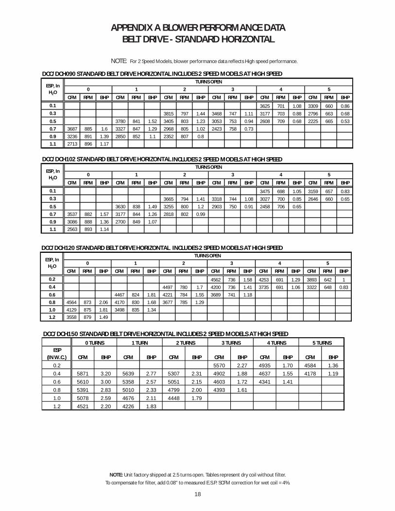
APPENDIX A BLOWER PERFORMANCE DATABELT DRIVE - STANDARD HORIZONTAL
NOTE: For 2 Speed Models, blower performance data reflects High speed performance.
NOTE: Unit factory shipped at 2.5 turns open. Tables represent dry coil without filter.To compensate for filter, add 0.08" to measured E.S.P. SCFM correction for wet coil = 4%.
DCC/DCH120 STANDARD BELT DRIVE HORIZONTAL INCLUDES 2 SPEED MODELS AT HIGH SPEED
CFM RPM BHP CFM RPM BHP CFM RPM BHP CFM RPM BHP CFM RPM BHP CFM RPM BHP
0.2 4562 736 1.58 4253 691 1.29 3893 642 10.4 4497 780 1.7 4200 736 1.41 3735 691 1.06 3322 648 0.830.6 4467 824 1.81 4221 784 1.55 3689 741 1.180.8 4564 873 2.06 4170 830 1.68 3677 785 1.291.0 4129 875 1.81 3498 835 1.341.2 3558 879 1.49
ESP, In H2O
TURNS OPEN0 1 2 3 4 5
DCC/DCH090 STANDARD BELT DRIVE HORIZONTAL
CFM RPM BHP CFM RPM BHP CFM RPM BHP CFM RPM BHP CFM RPM BHP CFM RPM BHP
0.1 3625 701 1.08 3309 660 0.860.3 3815 797 1.44 3468 747 1.11 3177 703 0.88 2796 663 0.680.5 3780 841 1.52 3405 803 1.23 3053 753 0.94 2608 709 0.68 2225 665 0.530.7 3687 885 1.6 3327 847 1.29 2968 805 1.02 2423 758 0.730.9 3236 891 1.39 2850 852 1.1 2352 807 0.81.1 2713 896 1.17
DCC/DCH102 STANDARD BELT DRIVE HORIZONTAL
CFM RPM BHP CFM RPM BHP CFM RPM BHP CFM RPM BHP CFM RPM BHP CFM RPM BHP
0.1 3475 698 1.05 3159 657 0.830.3 3665 794 1.41 3318 744 1.08 3027 700 0.85 2646 660 0.650.5 3630 838 1.49 3255 800 1.2 2903 750 0.91 2458 706 0.650.7 3537 882 1.57 3177 844 1.26 2818 802 0.990.9 3086 888 1.36 2700 849 1.071.1 2563 893 1.14
ESP, In H2O
TURNS OPEN0 1 2 3 4 5
TURNS OPENESP, In
H2O 4 50 1 2 3
DCC/DCH150 STANDARD BELT DRIVE HORIZONTAL INCLUDES 2 SPEED MODELS AT HIGH SPEED
ESP(IN W.C.) CFM BHP CFM BHP CFM BHP CFM BHP CFM BHP CFM BHP
0.2 5570 2.27 4935 1.70 4584 1.360.4 5871 3.20 5639 2.77 5307 2.31 4902 1.88 4637 1.55 4178 1.190.6 5610 3.00 5358 2.57 5051 2.15 4603 1.72 4341 1.410.8 5391 2.83 5010 2.33 4799 2.00 4393 1.611.0 5078 2.59 4676 2.11 4448 1.791.2 4521 2.20 4226 1.83
0 TURNS 1 TURN 2 TURNS 3 TURNS 4 TURNS 5 TURNS
INCLUDES 2 SPEED MODELS AT HIGH SPEED
INCLUDES 2 SPEED MODELS AT HIGH SPEED
19
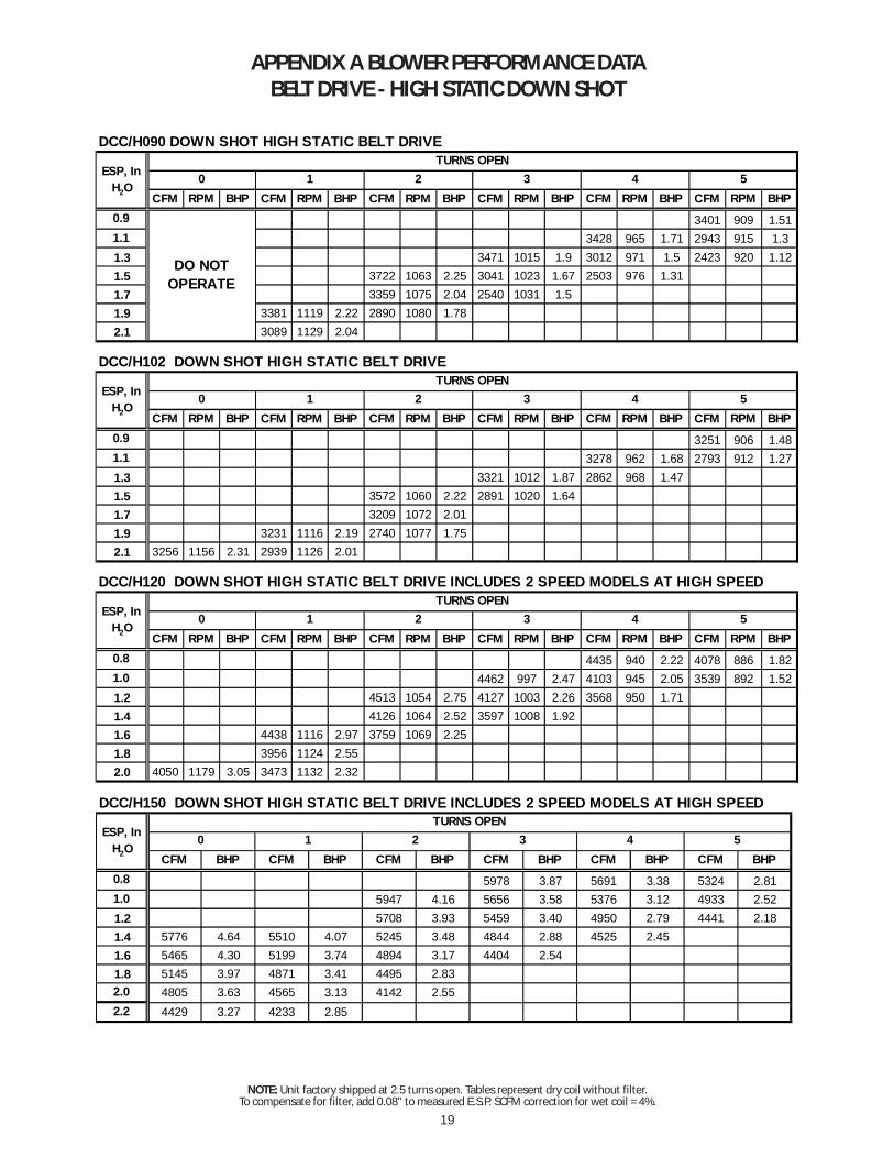
APPENDIX A BLOWER PERFORMANCE DATABELT DRIVE - HIGH STATIC DOWN SHOT
DCC/H090 DOWN SHOT HIGH STATIC BELT DRIVE
CFM RPM BHP CFM RPM BHP CFM RPM BHP CFM RPM BHP CFM RPM BHP CFM RPM BHP0.9 3401 909 1.511.1 3428 965 1.71 2943 915 1.31.3 3471 1015 1.9 3012 971 1.5 2423 920 1.121.5 3722 1063 2.25 3041 1023 1.67 2503 976 1.311.7 3359 1075 2.04 2540 1031 1.51.9 3381 1119 2.22 2890 1080 1.782.1 3089 1129 2.04
DCC/H102 DOWN SHOT HIGH STATIC BELT DRIVE
CFM RPM BHP CFM RPM BHP CFM RPM BHP CFM RPM BHP CFM RPM BHP CFM RPM BHP0.9 3251 906 1.481.1 3278 962 1.68 2793 912 1.271.3 3321 1012 1.87 2862 968 1.471.5 3572 1060 2.22 2891 1020 1.641.7 3209 1072 2.011.9 3231 1116 2.19 2740 1077 1.752.1 3256 1156 2.31 2939 1126 2.01
DCC/H120 DOWN SHOT HIGH STATIC BELT DRIVE INCLUDES 2 SPEED MODELS AT HIGH SPEED
CFM RPM BHP CFM RPM BHP CFM RPM BHP CFM RPM BHP CFM RPM BHP CFM RPM BHP0.8 4435 940 2.22 4078 886 1.821.0 4462 997 2.47 4103 945 2.05 3539 892 1.521.2 4513 1054 2.75 4127 1003 2.26 3568 950 1.711.4 4126 1064 2.52 3597 1008 1.921.6 4438 1116 2.97 3759 1069 2.251.8 3956 1124 2.552.0 4050 1179 3.05 3473 1132 2.32
ESP, In H2O
TURNS OPEN0 1 2 3 4 5
ESP, In H2O
4 52 3TURNS OPEN
ESP, In H2O
TURNS OPEN0 1 2 3 4 5
DO NOT OPERATE
0 1
DCC/H150 DOWN SHOT HIGH STATIC BELT DRIVE INCLUDES 2 SPEED MODELS AT HIGH SPEED
CFM BHP CFM BHP CFM BHP CFM BHP CFM BHP CFM BHP0.8 5978 3.87 5691 3.38 5324 2.811.0 5947 4.16 5656 3.58 5376 3.12 4933 2.521.2 5708 3.93 5459 3.40 4950 2.79 4441 2.181.4 5776 4.64 5510 4.07 5245 3.48 4844 2.88 4525 2.451.6 5465 4.30 5199 3.74 4894 3.17 4404 2.541.8 5145 3.97 4871 3.41 4495 2.832.0 4805 3.63 4565 3.13 4142 2.552.2 4429 3.27 4233 2.85
ESP, In H2O
TURNS OPEN0 1 2 3 4 5
NOTE: Unit factory shipped at 2.5 turns open. Tables represent dry coil without filter.To compensate for filter, add 0.08" to measured E.S.P. SCFM correction for wet coil = 4%.
20
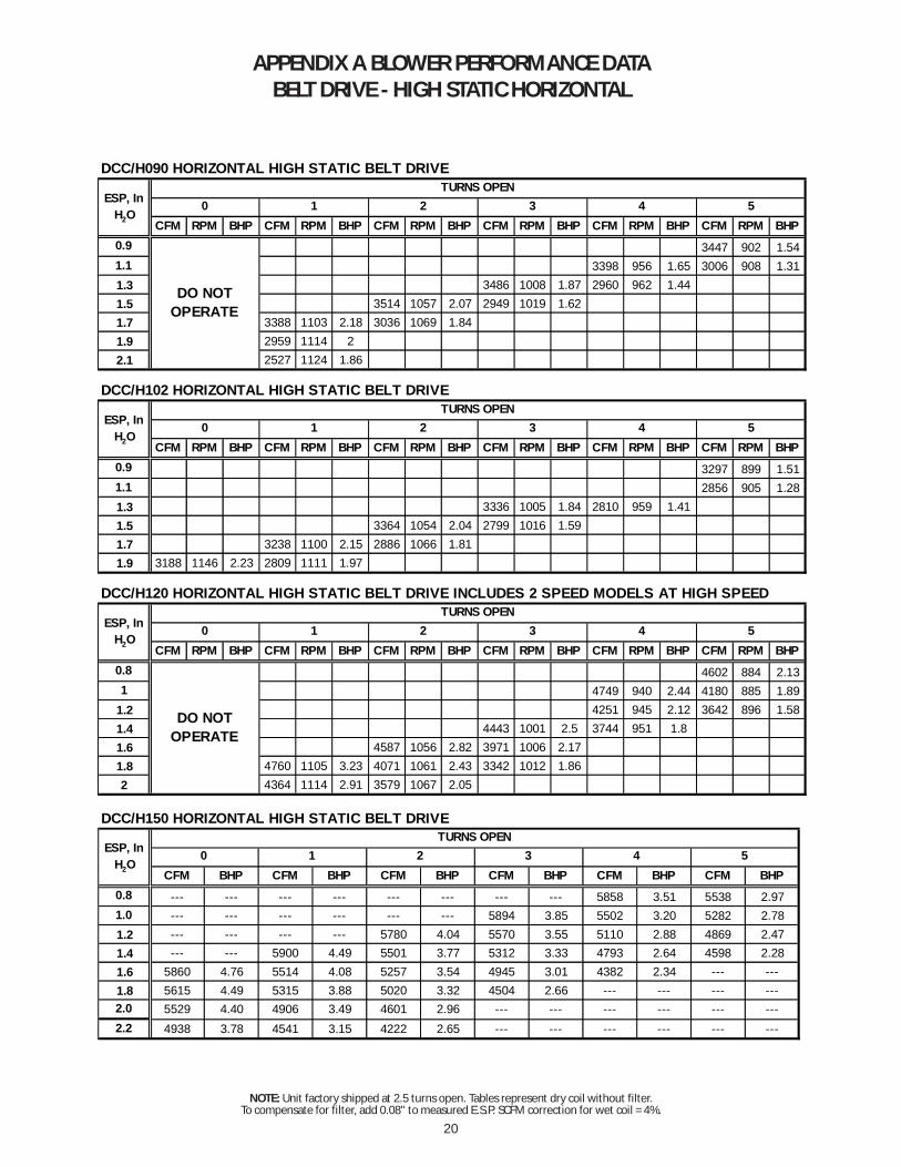
APPENDIX A BLOWER PERFORMANCE DATABELT DRIVE - HIGH STATIC HORIZONTAL
NOTE: Unit factory shipped at 2.5 turns open. Tables represent dry coil without filter.To compensate for filter, add 0.08" to measured E.S.P. SCFM correction for wet coil = 4%.
DCC/H090 HORIZONTAL HIGH STATIC BELT DRIVE
CFM RPM BHP CFM RPM BHP CFM RPM BHP CFM RPM BHP CFM RPM BHP CFM RPM BHP0.9 3447 902 1.541.1 3398 956 1.65 3006 908 1.311.3 3486 1008 1.87 2960 962 1.441.5 3514 1057 2.07 2949 1019 1.621.7 3388 1103 2.18 3036 1069 1.841.9 2959 1114 22.1 2527 1124 1.86
DCC/H102 HORIZONTAL HIGH STATIC BELT DRIVE
CFM RPM BHP CFM RPM BHP CFM RPM BHP CFM RPM BHP CFM RPM BHP CFM RPM BHP0.9 3297 899 1.511.1 2856 905 1.281.3 3336 1005 1.84 2810 959 1.411.5 3364 1054 2.04 2799 1016 1.591.7 3238 1100 2.15 2886 1066 1.811.9 3188 1146 2.23 2809 1111 1.97
DCC/H120 HORIZONTAL HIGH STATIC BELT DRIVE INCLUDES 2 SPEED MODELS AT HIGH SPEED
CFM RPM BHP CFM RPM BHP CFM RPM BHP CFM RPM BHP CFM RPM BHP CFM RPM BHP0.8 4602 884 2.131 4749 940 2.44 4180 885 1.89
1.2 4251 945 2.12 3642 896 1.581.4 4443 1001 2.5 3744 951 1.81.6 4587 1056 2.82 3971 1006 2.171.8 4760 1105 3.23 4071 1061 2.43 3342 1012 1.862 4364 1114 2.91 3579 1067 2.05
ESP, In H2O
TURNS OPEN0 1 2 3 4 5
DO NOT OPERATE
DO NOT OPERATE
ESP, In H2O
TURNS OPEN0 1 2 3 4 5
ESP, In H2O
TURNS OPEN0 1 2 3 4 5
DCC/H150 HORIZONTAL HIGH STATIC BELT DRIVE
CFM BHP CFM BHP CFM BHP CFM BHP CFM BHP CFM BHP0.8 --- --- --- --- --- --- --- --- 5858 3.51 5538 2.971.0 --- --- --- --- --- --- 5894 3.85 5502 3.20 5282 2.781.2 --- --- --- --- 5780 4.04 5570 3.55 5110 2.88 4869 2.471.4 --- --- 5900 4.49 5501 3.77 5312 3.33 4793 2.64 4598 2.281.6 5860 4.76 5514 4.08 5257 3.54 4945 3.01 4382 2.34 --- ---1.8 5615 4.49 5315 3.88 5020 3.32 4504 2.66 --- --- --- ---2.0 5529 4.40 4906 3.49 4601 2.96 --- --- --- --- --- ---2.2 4938 3.78 4541 3.15 4222 2.65 --- --- --- --- --- ---
ESP, In H2O
TURNS OPEN0 1 2 3 4 5

21
APPENDIX B ELECTRICAL DATA
ATTENTION INSTALLING PERSONNEL
Use only the heater kit specified for each model as dictated by the table above.
UNITHEATER KIT
MODEL NUMBERMINIMUM CFM
DownshotMINIMUM CFM
Horizontal
EHK*-16 3000 3200EHK*-30 3000 3200EHK*-45 3000 3200EHK*-16 3400 3400EHK*-30 3400 3400EHK*-45 3400 3400EHK*-16 3500 3500EHK*-30 3500 3500EHK*-45 4000 4000EHK*-16 4000 4000EHK*-30 4300 4300EHK*-45 4500 4500
MINIMUM AIR FLOW FOR ELECTRIC HEAT
12.5 TON
8.5 TON
7.5 TON
10 TON
MIN MAX Qty RLA LRA Qty HP FLA HP FLA HP FLA
208/230-60-3 187 253 2 13.1 83.1 2 1/4 1.40 BD STD STATIC 1.5 5.0 2 6.0
460-60-3 414 506 2 6.1 41.0 2 1/4 0.80 BD STD STATIC 1.5 2.5 2 2.9
575-60-3 518 633 2 4.4 33 2 1/4 0.55 BD STD STATIC 1.5 2.3 2 2.4
208/230-60-3 187 253 2 13.1 83.1 2 1/4 1.40 BD STD STATIC 2.0 7.8 2 6.0
460-60-3 414 506 2 6.1 41.0 2 1/4 0.80 BD STD STATIC 2.0 3.9 2 2.9
575-60-3 518 633 2 4.4 33 2 1/4 0.55 BD STD STATIC 2.0 2.5 2 2.4
208/230-60-3 187 253 2 14.5 98.0 2 1/4 1.40 BD STD STATIC 2.0 7.8 2 6.0
460-60-3 414 506 2 6.3 55.0 2 1/4 0.80 BD STD STATIC 2.0 3.9 2 2.9
575-60-3 518 633 2 6.0 41.0 2 1/4 0.55 BD STD STATIC 2.0 2.5 2 2.4
208/230-60-3 187 253 2 16.0 110.0 2 1/3 2.40 BD STD STATIC 2.0 7.8 2.0 6.4
460-60-3 414 506 2 7.8 52.0 2 1/3 1.20 BD STD STATIC 2.0 3.9 2.0 3.0
575-60-3 518 633 2 6.4 38.9 2 1/3 0.67 BD STD STATIC 2.0 2.5 2.0 2.4
208/230-60-3 187 253 2 22.4 149.0 2 1/3 2.40 BD STD STATIC 3.0 9.4 3.0 9.1
460-60-3 414 506 2 10.6 75.0 2 1/3 1.20 BD STD STATIC 3.0 4.7 3.0 4.3
575-60-3 518 633 2 7.70 54.0 2 1/3 0.67 BD STD STATIC 3.0 4.2 3.0 3.5
8.5 TON
10 TON
12.5 TON
ELECTRICAL DATA
MODELSVOLTAGE
(NAMEPLATE)
VOLTAGE LIMITATIONS
COMPRESSOR (ea) OD FAN MOTORS (ea) ID MOTOR APPL
ID FAN MOTOR (ea)
2 Speed ID Fan Motor (ea)
7.5 TONCOOLER
7.5 TONHEAT
PUMP
22
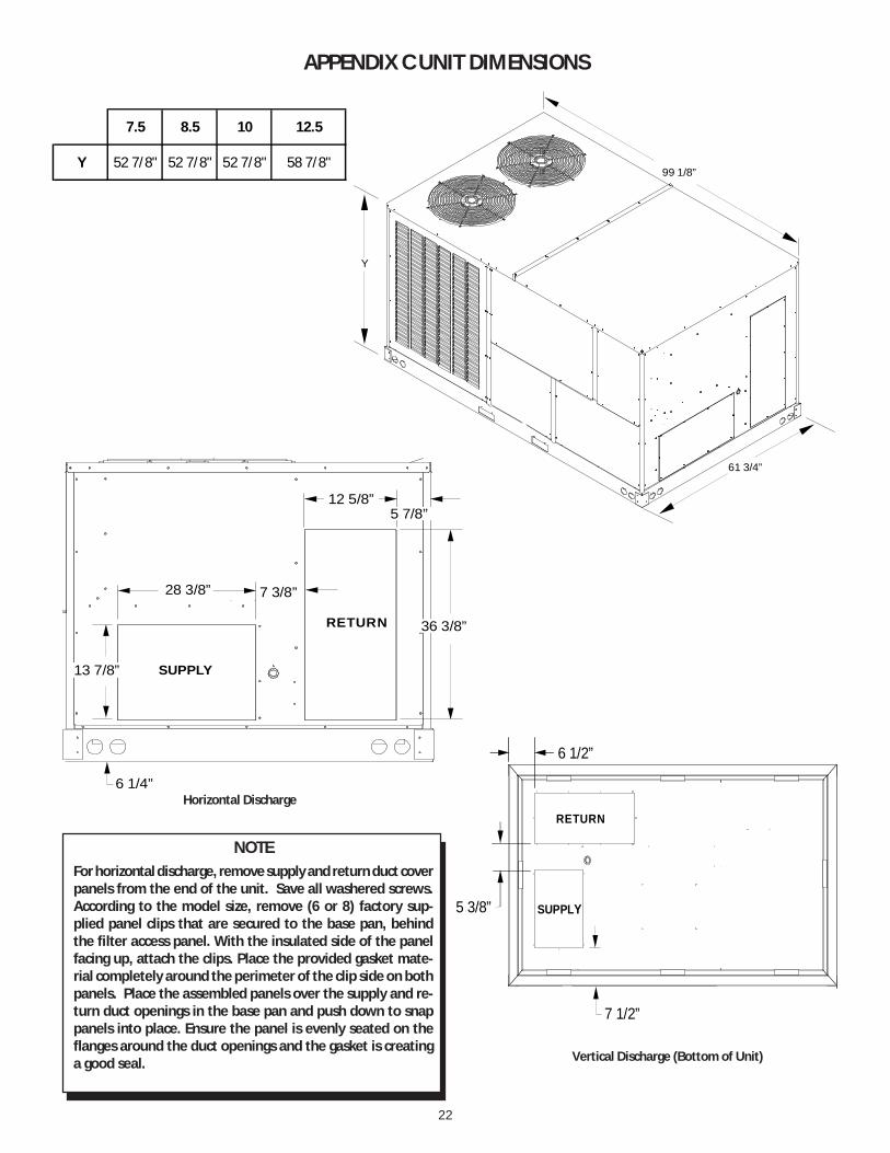
APPENDIX C UNIT DIMENSIONS
Horizontal Discharge
Vertical Discharge (Bottom of Unit)
RETURN
SUPPLY13 7/8”
28 3/8” 7 3/8”
12 5/8”
6 1/4”
36 3/8”
5 7/8”
RETURN
SUPPLY5 3/8”
7 1/2”
6 1/2”
NOTEFor horizontal discharge, remove supply and return duct coverpanels from the end of the unit. Save all washered screws.According to the model size, remove (6 or 8) factory sup-plied panel clips that are secured to the base pan, behindthe filter access panel. With the insulated side of the panelfacing up, attach the clips. Place the provided gasket mate-rial completely around the perimeter of the clip side on bothpanels. Place the assembled panels over the supply and re-turn duct openings in the base pan and push down to snappanels into place. Ensure the panel is evenly seated on theflanges around the duct openings and the gasket is creatinga good seal.
7.5 8.5 10 12.5
Y 52 7/8" 52 7/8" 52 7/8" 58 7/8"99 1/8”
61 3/4”
Y

23
Start-up Checklist*Store in job file
Pre Start-Up(Check each item as completed)
Verify all packaging material has been removed.
Remove all shipping brackets per installation instructions.
Verify the job site voltage agrees with the unit serial plate.
Verify condensate connection is installed per installation instructions.
Verify proper clearance around the unit for safety, service, maintenance and proper unit operation.
Verify proper weatherproofing of all ductwork, roof curbs and electrical connections.
Check that the flue screen is in place.
Check gas piping for leaks.
Verify gas pressure to the unit is within the range specified on the serial plate.
Check to ensure that all fans, pulleys and wheels are secure.
Check for proper belt tension and alignment per installation instructions.
Check refrigerant piping for rubbing and leaks. Repair if necessary.
Check unit wiring to ensure it is not in contact with refrigerant piping or sharp metal edges.
Check all electrical connections and terminals. Tighten as needed.
Verify that the crankcase heaters have been energized for 24 hours.
Verify the scroll compressor(s) are rotating in the right direction.
Verify all accessories are installed and operating correctly.
Check filters and replace if necessary.
Verify the installation of the thermostat.
9/2014
Date: ___________________________________
Model Number: ___________________________________
Serial Number: ___________________________________
Technician: ___________________________________
Location: __________________________________________
__________________________________________
__________________________________________
Unit #: __________________________________________
24
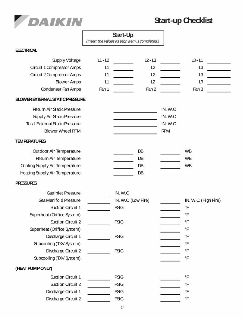
Start-up Checklist
L1 - L2 L2 - L3 L3 - L1
L1 L2 L3
L1 L2 L3
L1 L2 L3
Fan 1 Fan 2 Fan 3
IN. W.C.
IN. W.C.
IN. W.C.
RPM
DB WB
DB WB
DB WB
DB
IN. W.C.
IN. W.C. (Low Fire) IN. W.C. (High Fire)
PSIG °F
°F
PSIG °F
°F
PSIG °F
°F
PSIG °F
°F
PSIG °F
PSIG °F
PSIG °F
PSIG °F
BLOWER EXTERNAL STATIC PRESSURE
Return Air Static Pressure
Supply Air Static Pressure
Supply Voltage
Circuit 1 Compressor Amps
Circuit 2 Compressor Amps
Blower Amps
Condenser Fan Amps
ELECTRICAL
Total External Static Pressure
Blower Wheel RPM
TEMPERATURES
Outdoor Air Temperature
Return Air Temperature
Cooling Supply Air Temperature
Discharge Circuit 1
Heating Supply Air Temperature
PRESSURES
Gas Inlet Pressure
Gas Manifold Pressure
Suction Circuit 1
Suction Circuit 2
Discharge Circuit 2
Superheat (Orifice System)
Superheat (Orifice System)
Subcooling (TXV System)
Subcooling (TXV System)
Discharge Circuit 1
Discharge Circuit 2
(HEAT PUMP ONLY)
Suction Circuit 1
Suction Circuit 2
Start-Up(Insert the values as each item is completed.)