Installation Guide - Pioneer Ind
12
Engineering Excellence Installation Guide Single Handle Tub & Shower Valve Set: 4020B • This product meets the following standards: ASME A112.18.1 • ANSI A117.1 • ASSE 1016 • CUPC / IAPMO LISTED • Pioneer Industries, Inc. © 2011
Transcript of Installation Guide - Pioneer Ind

Engineering Excellence
Installation Guide
Single Handle Tub & Shower Valve Set:4020B•
This product meets the following standards: ASME A112.18.1 •ANSI A117.1 •ASSE 1016•CUPC / IAPMO LISTED •
Pioneer Industries, Inc. © 2011

Thank you for purchasing this Pioneer quality product.
Prior to Installation
Observe all local plumbing and building codes before you begin •installation.Carefully shut off both hot and cold main water supplies.•Pioneer reserves the right to make changes in the design of faucets without •noticeasspecifiedinthepricebook.
Caution: These products may cause personal injury due to scalding if the tempera-ture is set too high. We recommend that temperature is set below 120 ° F (49 ° C).
2
Tools Required
Propane Torch PEX Crimp Tool Adjustable-Wrench
TeflonTape
Lead-Free Solder
Hacksaw & Pipe Cutter
Straight & Phillips Screw- drivers

Thank you for purchasing this Pioneer quality product.
Prior to Installation
Observe all local plumbing and building codes before you begin •installation.Carefully shut off both hot and cold main water supplies.•Pioneer reserves the right to make changes in the design of faucets without •noticeasspecifiedinthepricebook.
Caution: These products may cause personal injury due to scalding if the tempera-ture is set too high. We recommend that temperature is set below 120 ° F (49 ° C).
2
Valve Installation
Determine the location of the valve. Install the required support framing. 1. Determinethedistancebetweenvalveoutletcenterlinetothefinishedwallsurface’A’ based on the Trim need to be installed from the Table. If the dimen-sion does not get follow then some trim may not be installed aesthetically.Remove inlet stop assembly, test cap before soldering.2. Locate the Valve and install 1/2” piping (B) and elbows (A) to bath and show-3. er outlets. Do not use more than one elbow (A) on the spout outlet. Ensure the ‘up’ marking on the valve face toward the ceiling. If this installation is for bath or shower only, cap shower or bath port accordingly. Do not forget to put thewasherunderneathofthecap.ApplysealantorTeflontapetothreadedconnections.
Caution: Do not use PEX or CPVC between the valve and tub spout.
Series ‘A’ Series ‘A’4LG100T~400T 2-1/8” 192X1XT-H5X 2-1/8”4DM100T~400T 2-1/4” 191X12T-HXX 2-1/4”4CB100T~400T 2-1/8” 1279X0T-H73 2-1/4”4PR100T~400T 2-1/4” 128970T-H85 1-3/4”1259X0T-H63 2” 128980T-H85 1-3/4”
3
Valve Installation
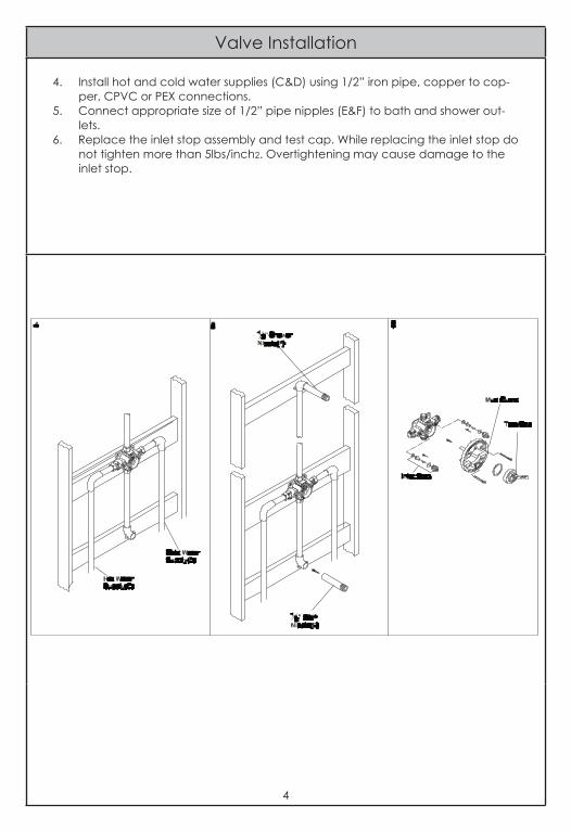
4. Install hot and cold water supplies (C&D) using 1/2” iron pipe, copper to cop-per, CPVC or PEX connections.
5. Connect appropriate size of 1/2” pipe nipples (E&F) to bath and shower out-lets.
6. Replace the inlet stop assembly and test cap. While replacing the inlet stop do not tighten more than 5lbs/inch2. Overtightening may cause damage to the inlet stop.
4

Valve Installation
7.Turnonmainwatersupplytoflushallthedebristhenturnoffmainwatersup-ply. For all installations, install caps (L) on the bath and shower nipples (E & F). Turn on the hot and cold water supplies and check for any leaks.
8. For thick or thin wall installation refer to the drawings. For Thick Wall Installation Determinethedistancebetweenvalveoutletcenterlinetothefinishedwallsurface ‘A’ based on the Trim need to be installed from the Table. If the dimen-sion does not get follow then some trim may not be installed aesthetically.
5
Valve Installation
4. Install hot and cold water supplies (C&D) using 1/2” iron pipe, copper to cop-per, CPVC or PEX connections.
5. Connect appropriate size of 1/2” pipe nipples (E&F) to bath and shower out-lets.
6. Replace the inlet stop assembly and test cap. While replacing the inlet stop do not tighten more than 5lbs/inch2. Overtightening may cause damage to the inlet stop.
4

3325S.GarfieldAve|CityofCommerce,CA90040Telephone:(800)338-9468|(323)888-8873|Fax:(323)888-9515
Hours: M - F, 7:30am to 5:00pm PST
Engineering Excellence
Installation Guide
Three Way Diverter Valve Set:199733B•
This product meets the following standards: ASME A112.18.1 •ANSI A117.1 •
Pioneer Industries, Inc. © 2011
Distinctive Living Redefined

Thank you for purchasing this pioneer quality product.
Prior to Installation
Observe all local plumbing and building codes before you begin •installation.Carefully shut off both hot and cold main water supplies.•Plug the tub drain with a soft cloth to prevent intrusion of debris or the loss of •any faucet parts. Pioneer reserves the right to make changes in the design of faucets without •noticeasspecifiedinthepricebook.
2
Tools Required
Propane Torch PEX Crimp Tool Adjustable-Wrench
TeflonTape
Lead-Free Solder
Hacksaw & Pipe Cutter
Straight & Phillips Screw- drivers
Thank you for purchasing this pioneer quality product.
Prior to Installation
Observe all local plumbing and building codes before you begin •installation.Carefully shut off both hot and cold main water supplies.•Plug the tub drain with a soft cloth to prevent intrusion of debris or the loss of •any faucet parts. Pioneer reserves the right to make changes in the design of faucets without •noticeasspecifiedinthepricebook.
2
Valve Installation
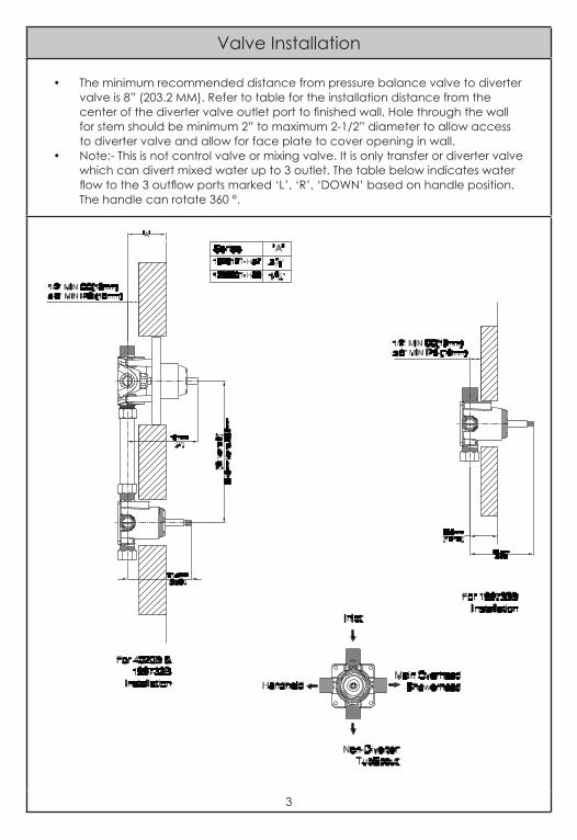
The minimum recommended distance from pressure balance valve to diverter •valve is 8” (203.2 MM). Refer to table for the installation distance from the centerofthedivertervalveoutletporttofinishedwall.Holethroughthewallfor stem should be minimum 2” to maximum 2-1/2” diameter to allow access to diverter valve and allow for face plate to cover opening in wall. Note:- This is not control valve or mixing valve. It is only transfer or diverter valve •which can divert mixed water up to 3 outlet. The table below indicates water flowtothe3outflowportsmarked‘L’,‘R’,‘DOWN’basedonhandleposition.The handle can rotate 360 °.
3

Valve Installation
For 1/2” IPS connection installation:- Install inlet mix water supply and outlets to •desired location piping to valve. Applyteflontapearoundvalveinlet&outletports.•Tighten the end of supply tube to inlet port with adjustable wrench.•
4
Valve Installation
For 1/2” IPS connection installation:- Install inlet mix water supply and outlets to •desired location piping to valve. Applyteflontapearoundvalveinlet&outletports.•Tighten the end of supply tube to inlet port with adjustable wrench.•
4
Valve Installation
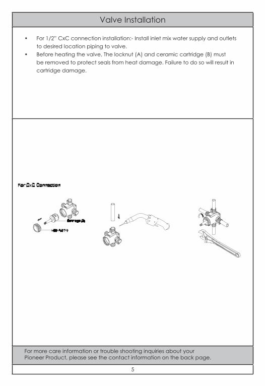
For 1/2” CxC connection installation:- Install inlet mix water supply and outlets •to desired location piping to valve.Before heating the valve, The locknut (A) and ceramic cartridge (B) must •be removed to protect seals from heat damage. Failure to do so will result in cartridge damage.
For more care information or trouble shooting inquiries about your Pioneer Product, please see the contact information on the back page.
5

3325S.GarfieldAve|CityofCommerce,CA90040Telephone:(800)338-9468|(323)888-8873|Fax:(323)888-9515
Hours: M - F, 7:30am to 5:00pm PST
Distinctive Living Redefined