Installation and User’s Guide -...
82
BladeCenter H Type 8852, 7989, and 1886 Installation and User’s Guide
Transcript of Installation and User’s Guide -...

BladeCenter H Type 8852, 7989, and 1886
Installation and User’s Guide
���

BladeCenter H Type 8852, 7989, and 1886
Installation and User’s Guide
���

NoteBefore using this information and the product it supports, read the general information in Appendix B, “Getting help andtechnical assistance,” on page 51 and Appendix C, “Notices,” on page 55.
Seventh Edition (December 2012)
© Copyright IBM Corporation 2012.US Government Users Restricted Rights – Use, duplication or disclosure restricted by GSA ADP Schedule Contractwith IBM Corp.
Contents
Safety . . . . . . . . . . . . . . . . . . . . . . . . . . . . v
Chapter 1. Introduction . . . . . . . . . . . . . . . . . . . . . . 1Locating and recording BladeCenter unit information . . . . . . . . . . . 2Features and specifications . . . . . . . . . . . . . . . . . . . . . 3The BladeCenter modules . . . . . . . . . . . . . . . . . . . . . 3
Advanced management module . . . . . . . . . . . . . . . . . . 4I/O modules . . . . . . . . . . . . . . . . . . . . . . . . . 4Blade servers . . . . . . . . . . . . . . . . . . . . . . . . . 4Power modules . . . . . . . . . . . . . . . . . . . . . . . . 5Blower modules . . . . . . . . . . . . . . . . . . . . . . . . 5
The IBM Documentation CD . . . . . . . . . . . . . . . . . . . . 5Hardware and software requirements . . . . . . . . . . . . . . . . 5Using the Documentation Browser . . . . . . . . . . . . . . . . . 6
Related documentation . . . . . . . . . . . . . . . . . . . . . . 6Notices and statements in this document . . . . . . . . . . . . . . . . 8Major components of the BladeCenter H unit . . . . . . . . . . . . . . 9
Chapter 2. BladeCenter unit power, controls, and indicators . . . . . . . 11Supplying power to the BladeCenter unit . . . . . . . . . . . . . . . 11Disconnecting power from the BladeCenter unit . . . . . . . . . . . . . 11BladeCenter components, controls, and LEDs . . . . . . . . . . . . . 12
Front view . . . . . . . . . . . . . . . . . . . . . . . . . 12Rear view . . . . . . . . . . . . . . . . . . . . . . . . . . 15
Chapter 3. Installing the BladeCenter unit and options . . . . . . . . . 17Installation checklist . . . . . . . . . . . . . . . . . . . . . . . 17Installing the BladeCenter unit in a rack . . . . . . . . . . . . . . . . 17Installation guidelines . . . . . . . . . . . . . . . . . . . . . . 18
System reliability guidelines . . . . . . . . . . . . . . . . . . . 18Handling static-sensitive devices . . . . . . . . . . . . . . . . . 18
Removing components before rack installation . . . . . . . . . . . . . 19Removing a power module . . . . . . . . . . . . . . . . . . . 19Removing a blade server . . . . . . . . . . . . . . . . . . . . 21Removing a management module . . . . . . . . . . . . . . . . . 21Removing a blower module . . . . . . . . . . . . . . . . . . . 22Removing an I/O module . . . . . . . . . . . . . . . . . . . . 22Removing a bezel . . . . . . . . . . . . . . . . . . . . . . . 23Removing an optical drive filler . . . . . . . . . . . . . . . . . . 24
Installing components . . . . . . . . . . . . . . . . . . . . . . 24Installing a blower module . . . . . . . . . . . . . . . . . . . . 24Installing a management module . . . . . . . . . . . . . . . . . 26Installing an I/O module . . . . . . . . . . . . . . . . . . . . 27Installing a power module . . . . . . . . . . . . . . . . . . . . 28Installing an optical drive . . . . . . . . . . . . . . . . . . . . 30Installing a bezel . . . . . . . . . . . . . . . . . . . . . . . 31Installing a blade server . . . . . . . . . . . . . . . . . . . . 31
Completing the installation. . . . . . . . . . . . . . . . . . . . . 32
Chapter 4. Configuration and networking guidelines . . . . . . . . . . 35Configuring the BladeCenter unit . . . . . . . . . . . . . . . . . . 35
Configuring the management module. . . . . . . . . . . . . . . . 35Configuring I/O modules . . . . . . . . . . . . . . . . . . . . 35
© Copyright IBM Corp. 2012 iii
Configuring blade servers . . . . . . . . . . . . . . . . . . . . 35Using IBM FastSetup . . . . . . . . . . . . . . . . . . . . . 36
BladeCenter networking guidelines . . . . . . . . . . . . . . . . . 36
Chapter 5. IBM Director . . . . . . . . . . . . . . . . . . . . . 37
Chapter 6. Shared BladeCenter resources . . . . . . . . . . . . . . 39
Chapter 7. Solving problems . . . . . . . . . . . . . . . . . . . 41Diagnostic tools overview . . . . . . . . . . . . . . . . . . . . . 41Troubleshooting tables . . . . . . . . . . . . . . . . . . . . . . 41
Monitor or video problems . . . . . . . . . . . . . . . . . . . . 42Power problems . . . . . . . . . . . . . . . . . . . . . . . 42Management module problems . . . . . . . . . . . . . . . . . . 43Blower module problems . . . . . . . . . . . . . . . . . . . . 43Media tray problems . . . . . . . . . . . . . . . . . . . . . . 44
Light path diagnostic LEDs . . . . . . . . . . . . . . . . . . . . 44Diagnosing problems using diagnostic LEDs . . . . . . . . . . . . . 44Diagnostic LEDs . . . . . . . . . . . . . . . . . . . . . . . 45
Appendix A. BladeCenter management-module configuration worksheet 47
Appendix B. Getting help and technical assistance . . . . . . . . . . 51Before you call . . . . . . . . . . . . . . . . . . . . . . . . . 51Using the documentation . . . . . . . . . . . . . . . . . . . . . 52Getting help and information from the World Wide Web . . . . . . . . . . 52How to send Dynamic System Analysis data to IBM . . . . . . . . . . . 52Creating a personalized support web page. . . . . . . . . . . . . . . 52Software service and support . . . . . . . . . . . . . . . . . . . 52Hardware service and support . . . . . . . . . . . . . . . . . . . 53IBM Taiwan product service . . . . . . . . . . . . . . . . . . . . 53
Appendix C. Notices . . . . . . . . . . . . . . . . . . . . . . 55Trademarks . . . . . . . . . . . . . . . . . . . . . . . . . . 55Important notes. . . . . . . . . . . . . . . . . . . . . . . . . 56Particulate contamination . . . . . . . . . . . . . . . . . . . . . 57Documentation format . . . . . . . . . . . . . . . . . . . . . . 57Telecommunication regulatory statement . . . . . . . . . . . . . . . 58Electronic emission notices . . . . . . . . . . . . . . . . . . . . 58
Federal Communications Commission (FCC) statement . . . . . . . . . 58Industry Canada Class A emission compliance statement . . . . . . . . 58Avis de conformité à la réglementation d'Industrie Canada . . . . . . . . 58Australia and New Zealand Class A statement . . . . . . . . . . . . 59European Union EMC Directive conformance statement . . . . . . . . . 59Germany Class A statement . . . . . . . . . . . . . . . . . . . 59VCCI Class A statement . . . . . . . . . . . . . . . . . . . . 60Japan Electronics and Information Technology Industries Association (JEITA)
statement . . . . . . . . . . . . . . . . . . . . . . . . . 60Korea Communications Commission (KCC) statement . . . . . . . . . 61Russia Electromagnetic Interference (EMI) Class A statement. . . . . . . 61People's Republic of China Class A electronic emission statement . . . . . 61Taiwan Class A compliance statement . . . . . . . . . . . . . . . 61
Index . . . . . . . . . . . . . . . . . . . . . . . . . . . . 63
iv BladeCenter H Type 8852, 7989, and 1886: Installation and User’s Guide
Safety
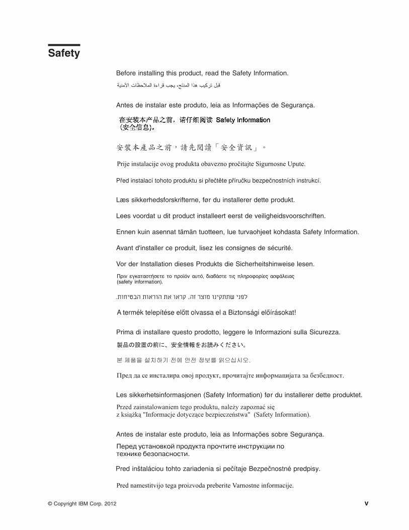
Before installing this product, read the Safety Information.
Antes de instalar este produto, leia as Informações de Segurança.
Læs sikkerhedsforskrifterne, før du installerer dette produkt.
Lees voordat u dit product installeert eerst de veiligheidsvoorschriften.
Ennen kuin asennat tämän tuotteen, lue turvaohjeet kohdasta Safety Information.
Avant d'installer ce produit, lisez les consignes de sécurité.
Vor der Installation dieses Produkts die Sicherheitshinweise lesen.
Prima di installare questo prodotto, leggere le Informazioni sulla Sicurezza.
Les sikkerhetsinformasjonen (Safety Information) før du installerer dette produktet.
Antes de instalar este produto, leia as Informações sobre Segurança.
© Copyright IBM Corp. 2012 v

Antes de instalar este producto, lea la información de seguridad.
Läs säkerhetsinformationen innan du installerar den här produkten.
Bu ürünü kurmadan önce güvenlik bilgilerini okuyun.
Important:
Each caution and danger statement in this document is labeled with a number. Thisnumber is used to cross reference an English-language caution or dangerstatement with translated versions of the caution or danger statement in the SafetyInformation document.
For example, if a caution statement is labeled "Statement 1", translations for thatcaution are in the Safety Information document under "Statement 1".
Be sure to read all caution and danger statements in this document before youperform the procedures. Read any additional safety information that comes with theserver or optional device before you install the device.
vi BladeCenter H Type 8852, 7989, and 1886: Installation and User’s Guide
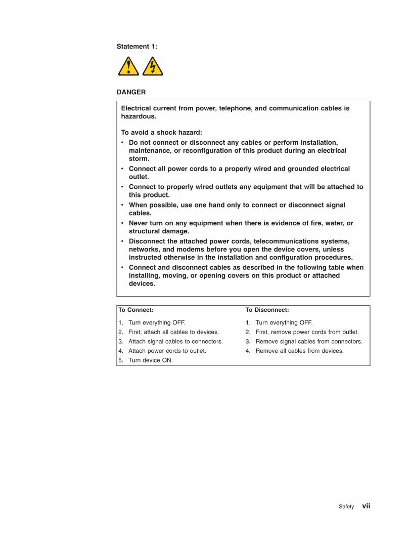
Statement 1:
DANGER
Electrical current from power, telephone, and communication cables ishazardous.
To avoid a shock hazard:
v Do not connect or disconnect any cables or perform installation,maintenance, or reconfiguration of this product during an electricalstorm.
v Connect all power cords to a properly wired and grounded electricaloutlet.
v Connect to properly wired outlets any equipment that will be attached tothis product.
v When possible, use one hand only to connect or disconnect signalcables.
v Never turn on any equipment when there is evidence of fire, water, orstructural damage.
v Disconnect the attached power cords, telecommunications systems,networks, and modems before you open the device covers, unlessinstructed otherwise in the installation and configuration procedures.
v Connect and disconnect cables as described in the following table wheninstalling, moving, or opening covers on this product or attacheddevices.
To Connect: To Disconnect:
1. Turn everything OFF.
2. First, attach all cables to devices.
3. Attach signal cables to connectors.
4. Attach power cords to outlet.
5. Turn device ON.
1. Turn everything OFF.
2. First, remove power cords from outlet.
3. Remove signal cables from connectors.
4. Remove all cables from devices.
Safety vii
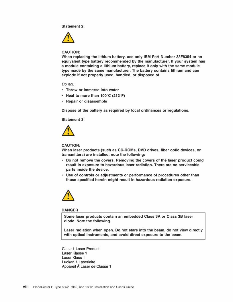
Statement 2:
CAUTION:When replacing the lithium battery, use only IBM Part Number 33F8354 or anequivalent type battery recommended by the manufacturer. If your system hasa module containing a lithium battery, replace it only with the same moduletype made by the same manufacturer. The battery contains lithium and canexplode if not properly used, handled, or disposed of.
Do not:
v Throw or immerse into water
v Heat to more than 100°C (212°F)
v Repair or disassemble
Dispose of the battery as required by local ordinances or regulations.
Statement 3:
CAUTION:When laser products (such as CD-ROMs, DVD drives, fiber optic devices, ortransmitters) are installed, note the following:
v Do not remove the covers. Removing the covers of the laser product couldresult in exposure to hazardous laser radiation. There are no serviceableparts inside the device.
v Use of controls or adjustments or performance of procedures other thanthose specified herein might result in hazardous radiation exposure.
DANGER
Some laser products contain an embedded Class 3A or Class 3B laserdiode. Note the following.
Laser radiation when open. Do not stare into the beam, do not view directlywith optical instruments, and avoid direct exposure to the beam.
Class 1 Laser ProductLaser Klasse 1Laser Klass 1Luokan 1 LaserlaiteAppareil A Laser de Classe 1`
viii BladeCenter H Type 8852, 7989, and 1886: Installation and User’s Guide
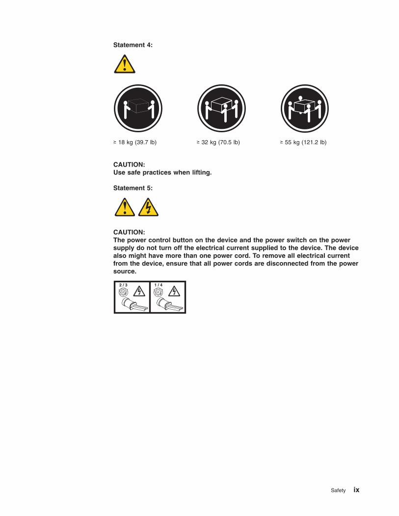
Statement 4:
≥ 18 kg (39.7 lb) ≥ 32 kg (70.5 lb) ≥ 55 kg (121.2 lb)
CAUTION:Use safe practices when lifting.
Statement 5:
CAUTION:The power control button on the device and the power switch on the powersupply do not turn off the electrical current supplied to the device. The devicealso might have more than one power cord. To remove all electrical currentfrom the device, ensure that all power cords are disconnected from the powersource.
2 / 3 1 / 4
Safety ix
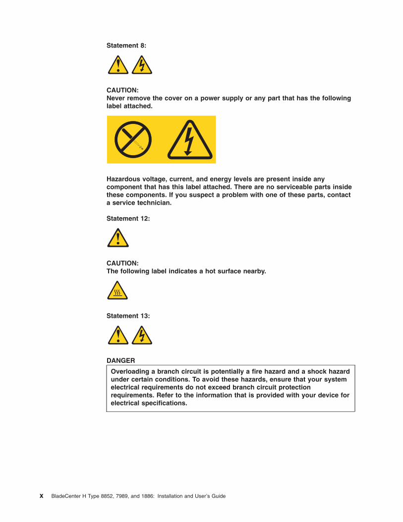
Statement 8:
CAUTION:Never remove the cover on a power supply or any part that has the followinglabel attached.
Hazardous voltage, current, and energy levels are present inside anycomponent that has this label attached. There are no serviceable parts insidethese components. If you suspect a problem with one of these parts, contacta service technician.
Statement 12:
CAUTION:The following label indicates a hot surface nearby.
Statement 13:
DANGER
Overloading a branch circuit is potentially a fire hazard and a shock hazardunder certain conditions. To avoid these hazards, ensure that your systemelectrical requirements do not exceed branch circuit protectionrequirements. Refer to the information that is provided with your device forelectrical specifications.
x BladeCenter H Type 8852, 7989, and 1886: Installation and User’s Guide
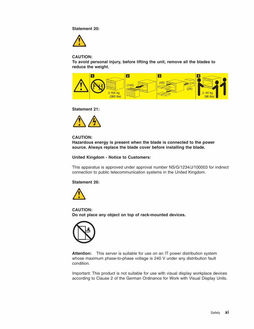
Statement 20:
CAUTION:To avoid personal injury, before lifting the unit, remove all the blades toreduce the weight.
(4X)
(2X)164 kg(360 lbs)
44 kg(96 lbs)
(14X)
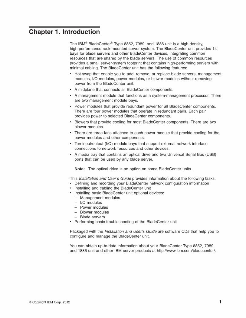
Statement 21:
CAUTION:Hazardous energy is present when the blade is connected to the powersource. Always replace the blade cover before installing the blade.
United Kingdom - Notice to Customers:
This apparatus is approved under approval number NS/G/1234/J/100003 for indirectconnection to public telecommunication systems in the United Kingdom.
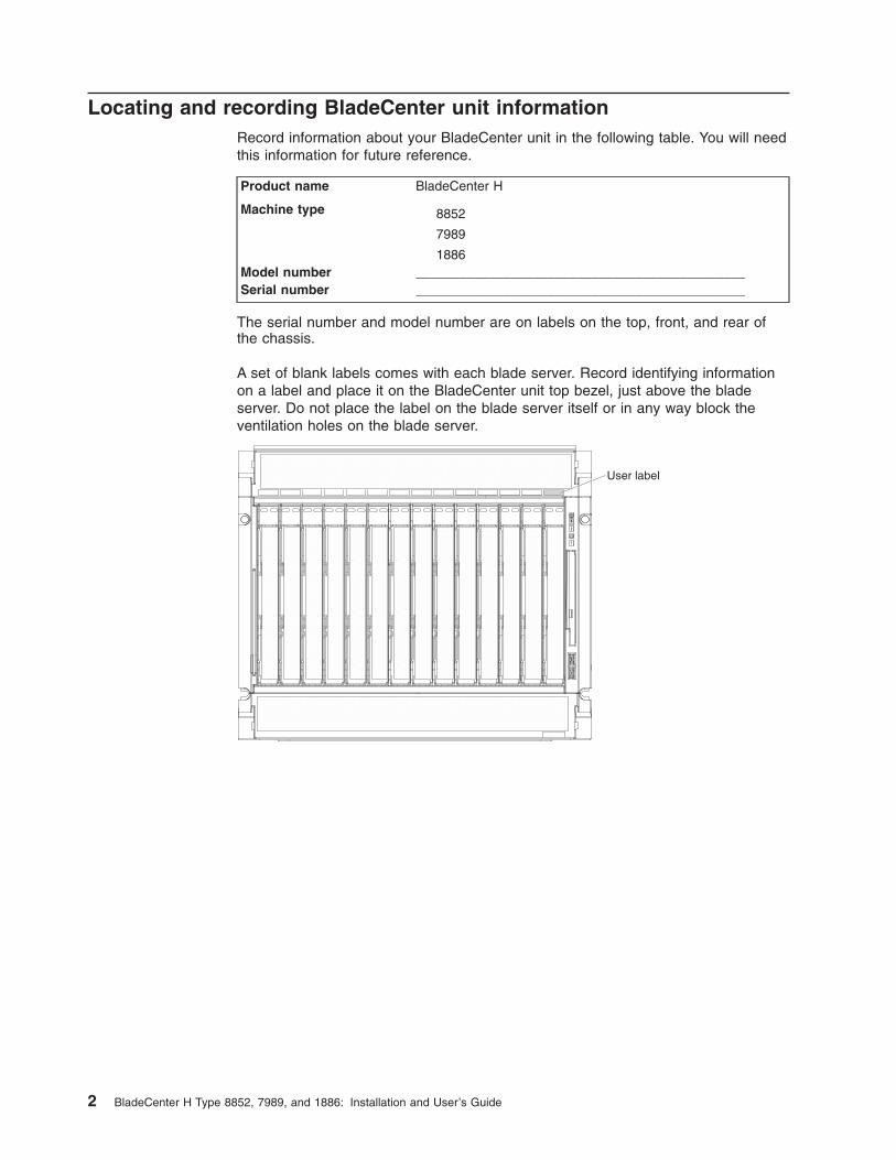
Statement 26:
CAUTION:Do not place any object on top of rack-mounted devices.
Attention: This server is suitable for use on an IT power distribution systemwhose maximum phase-to-phase voltage is 240 V under any distribution faultcondition.
Important: This product is not suitable for use with visual display workplace devicesaccording to Clause 2 of the German Ordinance for Work with Visual Display Units.
Safety xi

xii BladeCenter H Type 8852, 7989, and 1886: Installation and User’s Guide
Chapter 1. Introduction
The IBM® BladeCenter® Type 8852, 7989, and 1886 unit is a high-density,high-performance rack-mounted server system. The BladeCenter unit provides 14bays for blade servers and other BladeCenter devices, integrating commonresources that are shared by the blade servers. The use of common resourcesprovides a small server-system footprint that contains high-performing servers withminimal cabling. The BladeCenter unit has the following features:
v Hot-swap that enable you to add, remove, or replace blade servers, managementmodules, I/O modules, power modules, or blower modules without removingpower from the BladeCenter unit.
v A midplane that connects all BladeCenter components.
v A management module that functions as a system-management processor. Thereare two management module bays.
v Power modules that provide redundant power for all BladeCenter components.There are four power modules that operate in redundant pairs. Each pairprovides power to selected BladeCenter components.
v Blowers that provide cooling for most BladeCenter components. There are twoblower modules.
v There are three fans attached to each power module that provide cooling for thepower modules and other components.
v Ten input/output (I/O) module bays that support external network interfaceconnections to network resources and other devices.
v A media tray that contains an optical drive and two Universal Serial Bus (USB)ports that can be used by any blade server.
Note: The optical drive is an option on some BladeCenter units.
This Installation and User’s Guide provides information about the following tasks:v Defining and recording your BladeCenter network configuration informationv Installing and cabling the BladeCenter unitv Installing basic BladeCenter unit optional devices:
– Management modules– I/O modules– Power modules– Blower modules– Blade servers
v Performing basic troubleshooting of the BladeCenter unit
Packaged with the Installation and User’s Guide are software CDs that help you toconfigure and manage the BladeCenter unit.
You can obtain up-to-date information about your BladeCenter Type 8852, 7989,and 1886 unit and other IBM server products at http://www.ibm.com/bladecenter/.
© Copyright IBM Corp. 2012 1
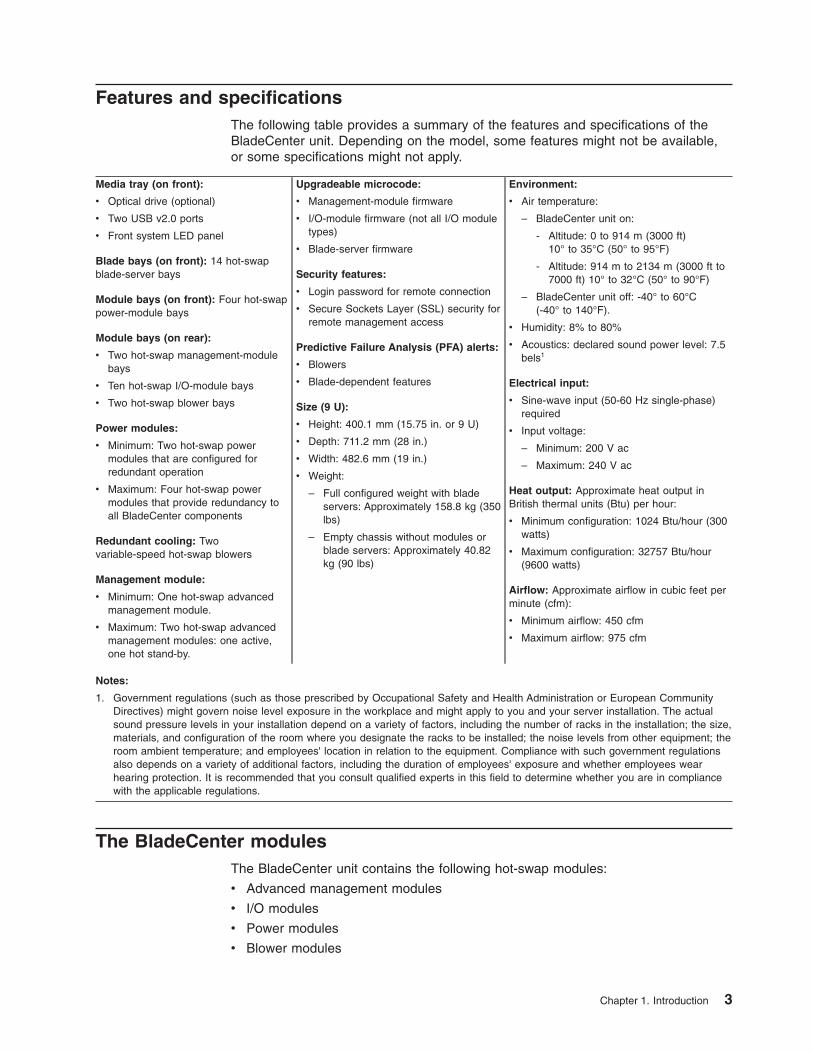
Locating and recording BladeCenter unit informationRecord information about your BladeCenter unit in the following table. You will needthis information for future reference.
Product name BladeCenter H
Machine type 8852
7989
1886Model number _____________________________________________Serial number _____________________________________________
The serial number and model number are on labels on the top, front, and rear ofthe chassis.
A set of blank labels comes with each blade server. Record identifying informationon a label and place it on the BladeCenter unit top bezel, just above the bladeserver. Do not place the label on the blade server itself or in any way block theventilation holes on the blade server.
2 BladeCenter H Type 8852, 7989, and 1886: Installation and User’s Guide
Features and specificationsThe following table provides a summary of the features and specifications of theBladeCenter unit. Depending on the model, some features might not be available,or some specifications might not apply.
Media tray (on front):
v Optical drive (optional)
v Two USB v2.0 ports
v Front system LED panel
Blade bays (on front): 14 hot-swapblade-server bays
Module bays (on front): Four hot-swappower-module bays
Module bays (on rear):
v Two hot-swap management-modulebays
v Ten hot-swap I/O-module bays
v Two hot-swap blower bays
Power modules:
v Minimum: Two hot-swap powermodules that are configured forredundant operation
v Maximum: Four hot-swap powermodules that provide redundancy toall BladeCenter components
Redundant cooling: Twovariable-speed hot-swap blowers
Management module:
v Minimum: One hot-swap advancedmanagement module.
v Maximum: Two hot-swap advancedmanagement modules: one active,one hot stand-by.
Upgradeable microcode:
v Management-module firmware
v I/O-module firmware (not all I/O moduletypes)
v Blade-server firmware
Security features:
v Login password for remote connection
v Secure Sockets Layer (SSL) security forremote management access
Predictive Failure Analysis (PFA) alerts:
v Blowers
v Blade-dependent features
Size (9 U):
v Height: 400.1 mm (15.75 in. or 9 U)
v Depth: 711.2 mm (28 in.)
v Width: 482.6 mm (19 in.)
v Weight:
– Full configured weight with bladeservers: Approximately 158.8 kg (350lbs)
– Empty chassis without modules orblade servers: Approximately 40.82kg (90 lbs)
Environment:
v Air temperature:
– BladeCenter unit on:
- Altitude: 0 to 914 m (3000 ft)10° to 35°C (50° to 95°F)
- Altitude: 914 m to 2134 m (3000 ft to7000 ft) 10° to 32°C (50° to 90°F)
– BladeCenter unit off: -40° to 60°C(-40° to 140°F).
v Humidity: 8% to 80%
v Acoustics: declared sound power level: 7.5bels1
Electrical input:
v Sine-wave input (50-60 Hz single-phase)required
v Input voltage:
– Minimum: 200 V ac
– Maximum: 240 V ac
Heat output: Approximate heat output inBritish thermal units (Btu) per hour:
v Minimum configuration: 1024 Btu/hour (300watts)
v Maximum configuration: 32757 Btu/hour(9600 watts)
Airflow: Approximate airflow in cubic feet perminute (cfm):
v Minimum airflow: 450 cfm
v Maximum airflow: 975 cfm
Notes:
1. Government regulations (such as those prescribed by Occupational Safety and Health Administration or European CommunityDirectives) might govern noise level exposure in the workplace and might apply to you and your server installation. The actualsound pressure levels in your installation depend on a variety of factors, including the number of racks in the installation; the size,materials, and configuration of the room where you designate the racks to be installed; the noise levels from other equipment; theroom ambient temperature; and employees' location in relation to the equipment. Compliance with such government regulationsalso depends on a variety of additional factors, including the duration of employees' exposure and whether employees wearhearing protection. It is recommended that you consult qualified experts in this field to determine whether you are in compliancewith the applicable regulations.
The BladeCenter modulesThe BladeCenter unit contains the following hot-swap modules:
v Advanced management modules
v I/O modules
v Power modules
v Blower modules
Chapter 1. Introduction 3
See “Major components of the BladeCenter H unit” on page 9 for the location ofeach module. These modules supply common functions to the blade servers thatare installed in the blade bays in the front of the BladeCenter unit.
The BladeCenter unit and the active management module make optional I/Odevices (optical drive, USB port, keyboard, video, and mouse) available to all theblade servers, selected by any one blade server at a time.
Advanced management moduleThe BladeCenter unit comes with one hot-swap management module inmanagement-module bay 1. You can add a second management-module inmanagement-module bay 2 to provide redundancy.
The management module is a hot-swap module that you use to configure andmanage BladeCenter components. See the User’s Guide that comes with themanagement module for more information.
I/O modulesThe BladeCenter unit has 10 hot-swap I/O module bays that are compatible withthree types of I/O modules (see “Rear view” on page 15 for the location of the I/Omodule bays). These bays can be used as follows:
v The modules in bays 1 and 2 such as Ethernet switches or pass-thru modules,provide a communication links for the first and second network interfacecontrollers (NICs) on each blade server. The modules in these bays must supportEthernet.
v The modules in bays 3 and 4 can be either of the following types, but themodules in both bays must be of the same type:
– Switch modules, which provide a communication link for the third and fourthNICs in each blade server. The modules in these bays must support the typeof network interface that is used in the corresponding blade-server NICs.When these bays are used this way, they are similar in function to bays 1 and2.
– Bridge modules, which provide links to bays 7 through 10 that can be used asadditional outputs for the I/O modules in those bays. When these bays areused this way, the modules in these bays are not directly linked to the bladeservers but bay 3 provides redundancy for the module in bay 5 and bay 4provides redundancy for bay 6.
v The modules in bays 5 and 6, such as bridge modules, provide links to bays 7through 10 that can be used as additional outputs for the I/O modules in thosebays. Bays 5 and 6 are not directly linked to the blade servers.
v The modules in bays 7 through 10, such as Infiniband switches, providehigh-speed communication links to the fifth through eighth NICs in each bladeserver. The modules in these bays must support the type of network interfacethat is used in the corresponding blade-server NICs.
Blade serversThe BladeCenter unit provides 14 bays for blade servers or other BladeCenterdevices. A blade server is a hot-swap, independent server with its own processors,memory, storage, network controllers, operating system, and applications. The bladeserver is installed in a bay in the BladeCenter unit and shares power, fans,switches, and ports with other blade servers.
4 BladeCenter H Type 8852, 7989, and 1886: Installation and User’s Guide
Power modulesThe BladeCenter unit comes with two or four hot-swap power modules.
Power modules are needed in bays 1 and 2 if you install blade servers in bladebays 1 through 7 or if you install I/O modules in I/O module bays 1 through 4 or 7through 10.
Power modules are needed in power module bays 3 and 4 if you install bladeservers in blade bays 8 through 14 or if you install I/O modules in any of I/Omodule bays 5 through 10.
Each pair of power modules is redundant. If either power module fails, theremaining power module continues to supply power, but there is no redundancy; thefailed power module must be replaced as soon as possible.
Blower modulesThe BladeCenter unit comes with two hot-swap blowers for cooling redundancy. Theblower speeds vary depending on the ambient air temperature at the front of theBladeCenter unit and the temperature of internal BladeCenter components. If theambient temperature is 25°C (77°F) or below, the BladeCenter unit blowers will runat their minimum rotational speed, increasing their speed as required to controlinternal BladeCenter temperature. If the ambient temperature is above 25°C (77°F),the blowers will run faster, increasing their speed as required to control internalBladeCenter unit temperature. If a blower fails, the operating speed of theremaining blower might increase and continue to cool the BladeCenter unit andblade servers. Replace a failed blower as soon as possible, to restore coolingredundancy.
Your BladeCenter might be equipped with standard blower modules (part number44E5083), or it might be equipped with high-efficiency blower modules (part number68Y8205). The standard and high-efficiency blower modules are notinterchangeable and should not be mixed in the same BladeCenter unit.
For a list of supported options for the BladeCenter, see the ServerProven® list athttp://www.ibm.com/servers/eserver/serverproven/compat/us/.
The IBM Documentation CDThe IBM BladeCenter Documentation CD contains documentation for yourBladeCenter unit in Portable Document Format (PDF) and includes the IBMDocumentation Browser to help you find information quickly.
Hardware and software requirementsThe IBM BladeCenter Documentation CD requires the following minimum hardwareand software:
v Microsoft Windows NT 4.0 (with Service Pack 3 or later), Windows 2000, or RedHat Linux
v 100 MHz microprocessor
v 32 MB RAM
v Adobe Acrobat Reader 3.0 (or later) or xpdf, which comes with Linux operatingsystems. Acrobat Reader software is included on the CD, and you can install itwhen you run the Documentation Browser.
Chapter 1. Introduction 5
Using the Documentation BrowserUse the Documentation Browser to browse the contents of the CD, read briefdescriptions of the documents, and view documents, using Adobe Acrobat Readeror xpdf. The Documentation Browser automatically detects the regional settings inuse in your system and presents the information in the language for that region (ifavailable). If a topic is not available in the language for that region, the Englishversion is displayed.
Use one of the following procedures to start the Documentation Browser:
v If Autostart is enabled, insert the CD into the drive. The Documentation Browserstarts automatically.
v If Autostart is disabled or is not enabled for all users:
– If you are using a Windows operating system, insert the CD into the drive;then, click Start → Run. In the Open field, typee:\win32.bat
where e is the drive letter of your optical drive, and click OK.
– If you are using a Red Hat Linux, insert the CD into the drive and run thefollowing command from the /mnt/cdrom directory:sh runlinux.sh
Select your computer from the Product menu. The Available Topics list displaysall the documents for your BladeCenter product. Some documents might be infolders. A plus sign (+) indicates each folder or document that has additional topicsunder it. Click the plus sign to display the additional documents.
When you select a document, a description of the document appears under TopicDescription. To select more than one document, press and hold the Ctrl key whileyou select the documents. Click View Book to view the selected document ordocuments in Acrobat Reader or xpdf. If you selected more than one document, allthe selected documents are opened in Acrobat Reader or xpdf.
To search all the documents, type a word or word string in the Search field andclick Search. The documents in which the word or word string appears are listed inorder of the most occurrences. Click a document to view it, and press Ctrl+F to usethe Acrobat search function or press Alt+F to use the xpdf search function within thedocument.
Click Help for detailed information about using the Documentation Browser.
Related documentationIn addition to this Installation and User’s Guide, the following related documentationis provided in Portable Document Format (PDF) at http://www.ibm.com/supportportal/ or on the BladeCenter Documentation CD that comes with yourBladeCenter unit:
v BladeCenter H Problem Determination and Service Guide
This document contains the information to help you solve problems, and itcontains information for service technicians.
v BladeCenter H Rack Installation Instructions
This printed document contains instructions for installing the BladeCenter unit ina rack.
v BladeCenter Advanced Management Module Installation Guide
6 BladeCenter H Type 8852, 7989, and 1886: Installation and User’s Guide
This document contains instructions for installing the management module in theBladeCenter unit and creating the initial configuration.
v BladeCenter Advanced Management Module User’s Guide
This document provides general information about the management module foryour BladeCenter unit type, including information about features, how toconfigure the management module, and how to get help.
v BladeCenter Advanced Management Module Command-Line Interface ReferenceGuide
This document explains how to use the management-module command-lineinterface to directly access BladeCenter management functions as an alternativeto using the Web-based user interface. The command-line interface also providesaccess to the text-console command prompt on each blade server through aSerial over LAN (SOL) connection.
v BladeCenter Advanced Management Module Messages Guide
This document contains a complete list of all non-device specific events andrecommended actions, sorted by event ID. Device specific event information is inthe documentation for the device.
v Safety Information
This document contains translated caution and danger statements. Each cautionand danger statement that appears in the documentation has a number that youcan use to locate the corresponding statement in your language in the SafetyInformation document.
v Safety Information Labels
This document provides the Simplified Chinese, Mongolian, Tibetan, Uygur, andZhuang translated versions of the product safety labels.
v Warranty
This document contains information about the terms of the warranty.
v Serial over LAN Setup Guide
This document explains how to update and configure BladeCenter componentsfor Serial over LAN (SOL) operation. The SOL connection provides access to thetext-console command prompt on each blade server and enables the bladeservers to be managed from a remote location.
Additional documents might be included on the IBM BladeCenter DocumentationCD.
Chapter 1. Introduction 7
Notices and statements in this documentThe caution and danger statements that appear in this document are also in themultilingual Safety Information document, which is on the IBM BladeCenterDocumentation CD. Each statement is numbered for reference to the correspondingstatement in the Safety Information document.
The following notices and statements are used in this document:
v Note: These notices provide important tips, guidance, or advice.
v Important: These notices provide information or advice that might help you avoidinconvenient or problem situations.
v Attention: These notices indicate possible damage to programs, devices, ordata. An attention notice is placed just before the instruction or situation in whichdamage could occur.
v Caution: These statements indicate situations that can be potentially hazardousto you. A caution statement is placed just before the description of a potentiallyhazardous procedure step or situation.
v Danger: These statements indicate situations that can be potentially lethal orextremely hazardous to you. A danger statement is placed just before thedescription of a potentially lethal or extremely hazardous procedure step orsituation.
8 BladeCenter H Type 8852, 7989, and 1886: Installation and User’s Guide
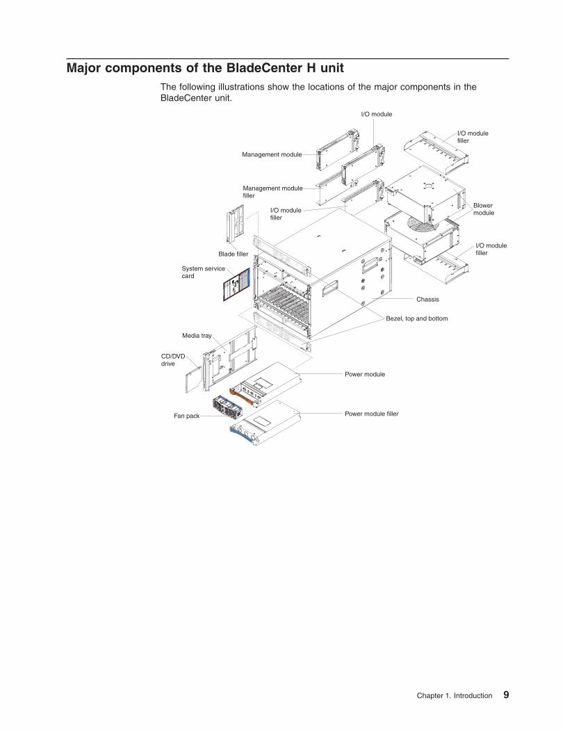
Major components of the BladeCenter H unitThe following illustrations show the locations of the major components in theBladeCenter unit.
3rd
pow
er
module
4th
pow
er
module
Ho
t-S
wa
p P
ow
er M
od
ule
AC
OK
Descr ip
t ion
an
d A
ctio
nP
ow
er M
od
ule
LE
Ds
Handle
(open)
Lig
ht P
ath
Dia
gn
ostic
sB
lad
eC
en
ter S
yste
m L
ED
Pan
el - P
r imary
Bla
de S
erv
er C
on
trol P
an
el - S
eco
nd
ary
CD
See h
ard
ware
for a
ctu
al lo
cat io
n o
f LE
Ds a
nd b
utto
ns.
See h
ard
ware
for a
ctu
al lo
catio
n o
f LE
Ds a
nd b
utto
ns.
DC
OK
Bla
deC
ente
rS
erv
ice
Info
rmatio
n®
I/O module
I/O modulefiller
I/O modulefiller
I/O modulefiller
Blowermodule
Chassis
Bezel, top and bottom
Power module
Power module fillerFan pack
CD/DVDdrive
Media tray
System servicecard
Blade filler
Management modulefiller
Management module
Chapter 1. Introduction 9

10 BladeCenter H Type 8852, 7989, and 1886: Installation and User’s Guide
Chapter 2. BladeCenter unit power, controls, and indicators
This section describes the controls and light-emitting diodes (LEDs) and how tostart and shut down the BladeCenter unit.
Supplying power to the BladeCenter unitTo supply power to the BladeCenter unit, connect one end of each power cord to apower connector on the rear of the BladeCenter unit and the other end of eachpower cord to a 220-volt power distribution unit or appropriate electrical outlet. TheBladeCenter unit does not have a power switch.
The blade servers in the BladeCenter unit are connected to power but are notturned on. After the BladeCenter unit has power, depending on the configurationsettings, the blade servers might have to be individually turned on.
Disconnecting power from the BladeCenter unitYou can shut down the BladeCenter unit by turning off the blade servers anddisconnecting the BladeCenter unit from the power source.
To disconnect power from the BladeCenter unit, complete the following steps:
1. Shut down each blade server. See the documentation that comes with yourblade servers for the procedure for shutting down the operating system.
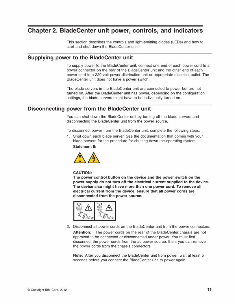
Statement 5:
CAUTION:The power control button on the device and the power switch on thepower supply do not turn off the electrical current supplied to the device.The device also might have more than one power cord. To remove allelectrical current from the device, ensure that all power cords aredisconnected from the power source.
2 / 3 1 / 4
2. Disconnect all power cords on the BladeCenter unit from the power connectors.
Attention: The power cords on the rear of the BladeCenter chassis are notapproved to be connected or disconnected under power. You must firstdisconnect the power cords from the ac power source; then, you can removethe power cords from the chassis connectors.
Note: After you disconnect the BladeCenter unit from power, wait at least 5seconds before you connect the BladeCenter unit to power again.
© Copyright IBM Corp. 2012 11

BladeCenter components, controls, and LEDsThis section identifies the components, controls, and LEDs on the front and rear ofthe BladeCenter unit.
Front viewThis section identifies the components, controls, and LEDs on the front of theBladeCenter unit.
Front systemLED panel
Optical driveeject button
Bladeservercontrolpanel
USB connectors
Optical driveactivity LED
Systemservicecards
Power module 1 Power modulebay 3
Media tray
Power module 2 Power modulebay 4
Power modulesThe following illustration shows the LEDs on each power module.
Fan error LED
Power module error LEDAC power LED
DC power LED
The LEDs on each power module indicate the condition of the power module andfan pack.
Note: The orientation of the power module shown in the illustration is for one of thetop power-modules. The orientation for modules in the bottom power-module baysis rotated 180°.
v DC power LED: When this green LED is lit, the dc output from the powermodule to the other components and blade servers is present and withinspecifications. During typical operation, both the ac power and dc power LEDsare lit.
v AC power LED: When this green LED is lit, ac input to the power module ispresent and within specifications. During typical operation, both the ac power anddc power LEDs are lit.
12 BladeCenter H Type 8852, 7989, and 1886: Installation and User’s Guide
v Power module error LED: When this amber LED is lit, a power module failurehas occurred and it is not operating within specifications.
v Fan error LED: When this amber LED is lit, a fan pack has failed and is notoperating within specifications.
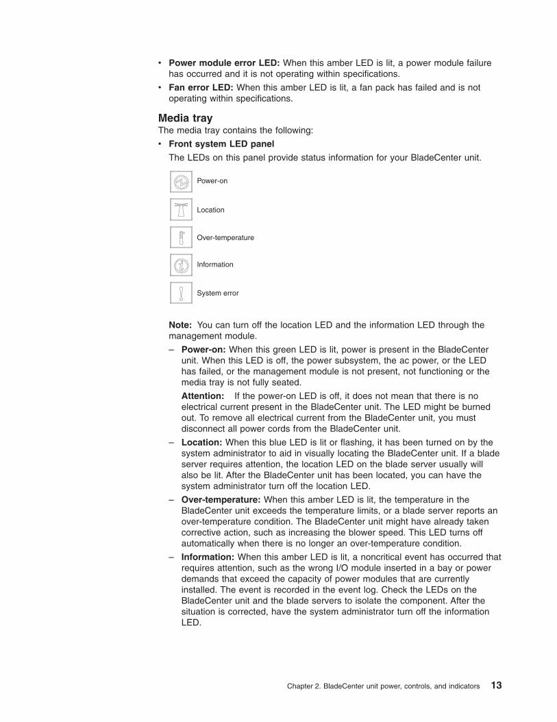
Media trayThe media tray contains the following:
v Front system LED panel
The LEDs on this panel provide status information for your BladeCenter unit.
Power-on
Location
Over-temperature
Information
System error
Note: You can turn off the location LED and the information LED through themanagement module.
– Power-on: When this green LED is lit, power is present in the BladeCenterunit. When this LED is off, the power subsystem, the ac power, or the LEDhas failed, or the management module is not present, not functioning or themedia tray is not fully seated.
Attention: If the power-on LED is off, it does not mean that there is noelectrical current present in the BladeCenter unit. The LED might be burnedout. To remove all electrical current from the BladeCenter unit, you mustdisconnect all power cords from the BladeCenter unit.
– Location: When this blue LED is lit or flashing, it has been turned on by thesystem administrator to aid in visually locating the BladeCenter unit. If a bladeserver requires attention, the location LED on the blade server usually willalso be lit. After the BladeCenter unit has been located, you can have thesystem administrator turn off the location LED.
– Over-temperature: When this amber LED is lit, the temperature in theBladeCenter unit exceeds the temperature limits, or a blade server reports anover-temperature condition. The BladeCenter unit might have already takencorrective action, such as increasing the blower speed. This LED turns offautomatically when there is no longer an over-temperature condition.
– Information: When this amber LED is lit, a noncritical event has occurred thatrequires attention, such as the wrong I/O module inserted in a bay or powerdemands that exceed the capacity of power modules that are currentlyinstalled. The event is recorded in the event log. Check the LEDs on theBladeCenter unit and the blade servers to isolate the component. After thesituation is corrected, have the system administrator turn off the informationLED.
Chapter 2. BladeCenter unit power, controls, and indicators 13
– System-error: When this amber LED is lit, it indicates that a system error hasoccurred, such as a failed module or a system error in a blade server. An LEDon one of the components or on a blade server is also lit to further isolate theerror.
v Optical drive activity LED: When this LED is lit, it indicates that the optical driveis in use.
v Optical drive eject button: Press this button to release a disc from the opticaldrive.
v USB connectors: Use these connectors to attach USB devices.
System service cardsThese cards contain system service instructions and a writable area. They slide inand out of the storage location on the left side of the BladeCenter unit.
Blade server control panelThis panel contains indicators and controls for the blade server. See thedocumentation that comes with your blade server for information about the bladeserver control panel.
14 BladeCenter H Type 8852, 7989, and 1886: Installation and User’s Guide
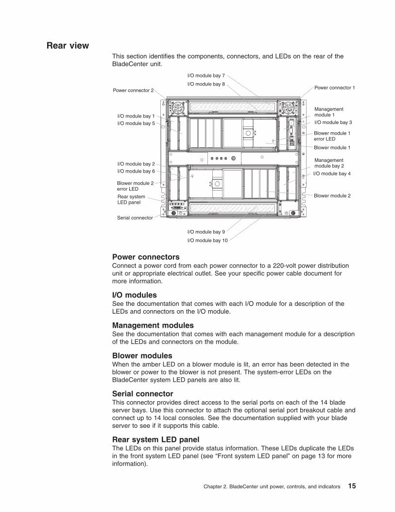
Rear viewThis section identifies the components, connectors, and LEDs on the rear of theBladeCenter unit.
I/O module bay 4
I/O module bay 3
I/O module bay 2
I/O module bay 6
I/O module bay 1
I/O module bay 7
I/O module bay 9
I/O module bay 8
I/O module bay 10
I/O module bay 5
Power connector 2 Power connector 1
Managementmodule 1
Managementmodule bay 2
Blower module 1
Blower module 1error LED
Blower module 2error LED
Blower module 2Rear systemLED panel
Serial connector
Power connectorsConnect a power cord from each power connector to a 220-volt power distributionunit or appropriate electrical outlet. See your specific power cable document formore information.
I/O modulesSee the documentation that comes with each I/O module for a description of theLEDs and connectors on the I/O module.
Management modulesSee the documentation that comes with each management module for a descriptionof the LEDs and connectors on the module.
Blower modulesWhen the amber LED on a blower module is lit, an error has been detected in theblower or power to the blower is not present. The system-error LEDs on theBladeCenter system LED panels are also lit.
Serial connectorThis connector provides direct access to the serial ports on each of the 14 bladeserver bays. Use this connector to attach the optional serial port breakout cable andconnect up to 14 local consoles. See the documentation supplied with your bladeserver to see if it supports this cable.
Rear system LED panelThe LEDs on this panel provide status information. These LEDs duplicate the LEDsin the front system LED panel (see “Front system LED panel” on page 13 for moreinformation).
Chapter 2. BladeCenter unit power, controls, and indicators 15

16 BladeCenter H Type 8852, 7989, and 1886: Installation and User’s Guide
Chapter 3. Installing the BladeCenter unit and options
This chapter provides instructions for installing the BladeCenter unit into a rack andadding optional devices to your BladeCenter unit. Some removal instructions areprovided in case you have to remove one device to install another.
Installation checklistBefore you can use the BladeCenter unit, you must set up and configure theBladeCenter unit, and install and configure the required components in theBladeCenter unit. If you have not already done so, perform the activities on thefollowing checklist:
__ 1. Set up the rack in which you will install the BladeCenter unit. See thedocumentation that comes with your rack.
__ 2. Determine the BladeCenter unit configuration settings, such as the IPaddress, network address, and Wake on LAN setting. Record theBladeCenter configuration setting information in Appendix A, “BladeCentermanagement-module configuration worksheet,” on page 47. See theBladeCenter Management Module User’s Guide that comes with yourmanagement module for instructions to configure an IP address.
__ 3. Remove any modules that come installed in the BladeCenter unit to reducethe weight of the unit you install into the rack. See “Removing componentsbefore rack installation” on page 19 for instructions.
__ 4. Install the BladeCenter unit into the rack. See the BladeCenter H RackInstallation Instructions.
__ 5. Reinstall the removed modules in the BladeCenter unit. Make sure that theBladeCenter unit has adequate power to support all of the installedcomponents. The BladeCenter unit must contain either two or four powermodules.
__ 6. Install the required BladeCenter unit components.
__ 7. Make sure that the latest level of firmware is installed on all of theBladeCenter components. See http://www.ibm.com/support/ for additionalinformation.
__ 8. Configure the management module in the BladeCenter unit. See theBladeCenter Advanced Management Module Installation Guide that comeswith your management module for information and instructions.
__ 9. Configure the I/O modules in the BladeCenter unit. See the documentationfor your I/O modules for configuration information.
__ 10. Configure the blade servers. See the Installation and User's Guide thatcomes with your blade server for information and instructions.
Installing the BladeCenter unit in a rackInstall the BladeCenter unit in a rack before you install any modules or bladeservers in the BladeCenter unit. If your BladeCenter unit is preconfigured with bladeservers, power modules, management modules, and blowers already installed,remove them first to reduce the weight. Detailed instructions for installing aBladeCenter unit in a rack are in the BladeCenter H Rack Installation Instructionsthat come with the BladeCenter unit.
© Copyright IBM Corp. 2012 17
Installation guidelinesBefore you install options in the BladeCenter unit, read the following information:
v Read the safety information that begins on page v and the guidelines in“Handling static-sensitive devices.” This information will help you work safely.
v Orange on a component or an orange label on or near a component indicatesthat the component can be hot-swapped, which means that you can remove orinstall the component while the BladeCenter unit is running. (Orange can alsoindicate touch points on hot-swap components.) See the instructions for removingor installing a specific hot-swap component for any additional procedures thatyou might have to perform before you remove or install the component.
v You do not have to disconnect the BladeCenter unit from power to install orreplace any of the hot-swap modules in the BladeCenter unit. You must shutdown the operating system and turn off a hot-swap blade server before youremove the blade server, but you do not have to shut down the BladeCenter unititself.
v Blue on a component indicates touch points where you can grip the componentto remove it from or install it in the BladeCenter unit, open and close a latch, andso on.
v For a list of supported options for the BladeCenter unit, seehttp://www.ibm.com/bladecenter/
System reliability guidelinesTo help ensure proper cooling and system reliability, make sure that the followingrequirements are met:
v Each of the module bays on the rear of the BladeCenter unit has either a moduleor a module filler installed.
v Each of the blade bays on the front of the BladeCenter unit has either a bladeserver or a blade filler installed.
v Each of the drive bays in a blade-server storage expansion option has either ahot-swap drive or a filler panel installed.
v A removed hot-swap module, blade server, or drive is replaced within 1 minute ofremoval.
v Cables for the optional modules are routed according to the illustrations andinstructions in this document.
v A failed blower is replaced as soon as possible, to restore cooling redundancy.
Handling static-sensitive devices
Attention: Static electricity can damage the BladeCenter unit and other electronicdevices. To avoid damage, keep static-sensitive devices in their static-protectivepackages until you are ready to install them.
To reduce the possibility of electrostatic discharge, observe the followingprecautions:
v Limit your movement. Movement can cause static electricity to build up aroundyou.
v Handle the device carefully, holding it by its edges or its frame.
v Do not touch solder joints, pins, or exposed printed circuitry.
v Do not leave the device where others can handle and damage it.
18 BladeCenter H Type 8852, 7989, and 1886: Installation and User’s Guide
v While the device is still in its static-protective package, touch it to an unpaintedmetal part of the BladeCenter unit or rack for at least 2 seconds. This drainsstatic electricity from the package and from your body.
v Remove the device from its package and install it immediately without settingdown. If it is necessary to set down the device, put it back into itsstatic-protective package.
v Take additional care when handling devices during cold weather. Heating reducesindoor humidity and increases static electricity.
Removing components before rack installationAttention: See the BladeCenter H Problem Determination and Service Guide forremoving components from the BladeCenter unit when the unit is connected topower.
Use the following procedures to remove components from the BladeCenter unitbefore you install it in a rack and connect to power.
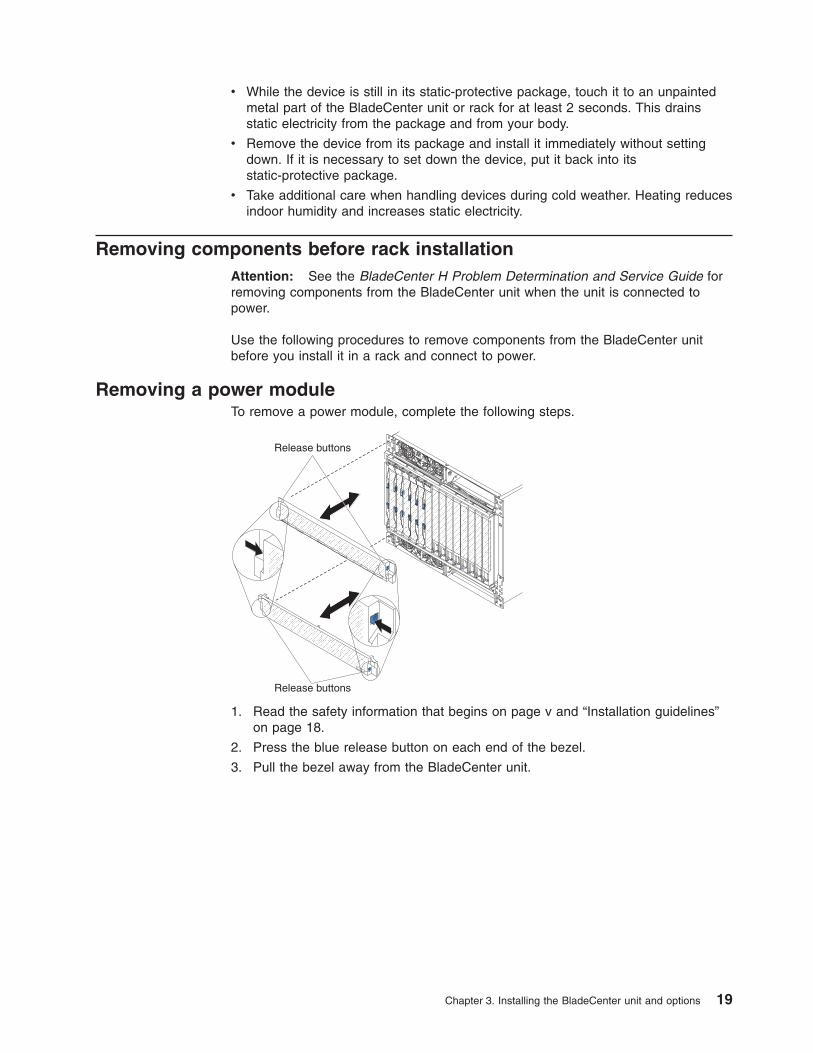
Removing a power moduleTo remove a power module, complete the following steps.
Release buttons
Release buttons
1. Read the safety information that begins on page v and “Installation guidelines”on page 18.
2. Press the blue release button on each end of the bezel.
3. Pull the bezel away from the BladeCenter unit.
Chapter 3. Installing the BladeCenter unit and options 19
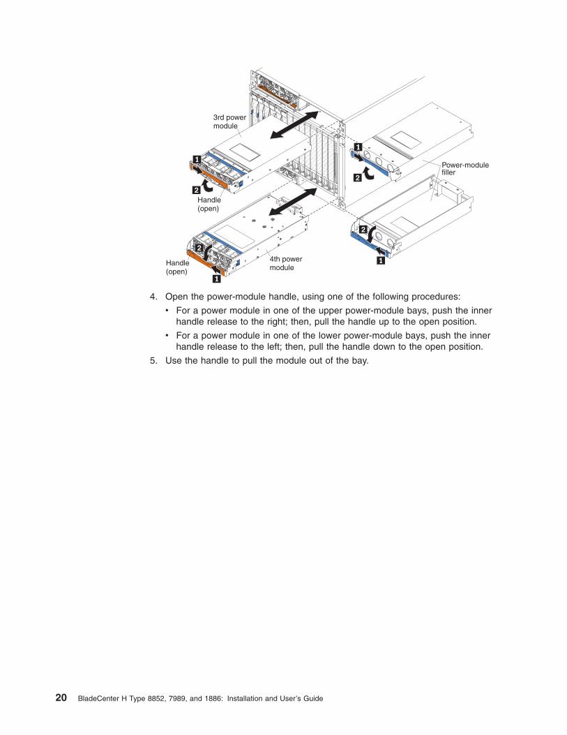
3rd powermodule
4th powermodule
Power-modulefiller
Handle(open)
Handle(open)
4. Open the power-module handle, using one of the following procedures:
v For a power module in one of the upper power-module bays, push the innerhandle release to the right; then, pull the handle up to the open position.
v For a power module in one of the lower power-module bays, push the innerhandle release to the left; then, pull the handle down to the open position.
5. Use the handle to pull the module out of the bay.
20 BladeCenter H Type 8852, 7989, and 1886: Installation and User’s Guide
Removing a blade serverAttention: Note the bay number. Reinstalling a blade server into a different baythan the one from which it was removed could have unintended consequences.Some configuration information and update options are established according tobay number.
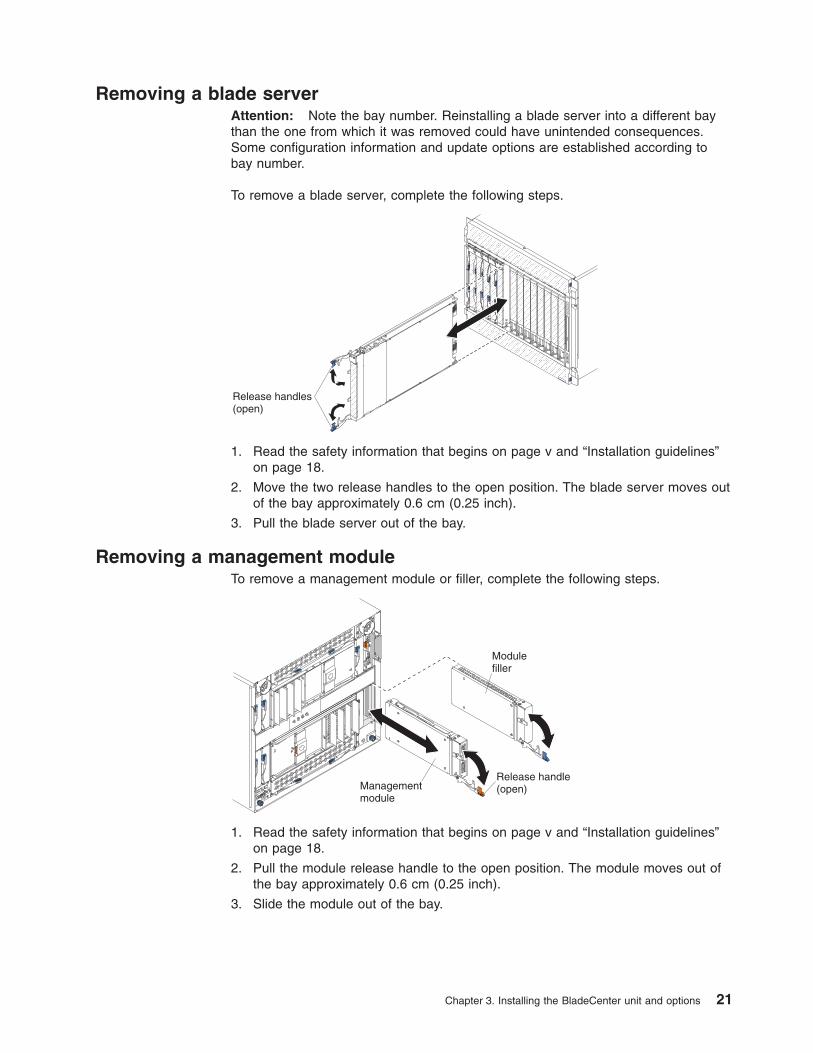
To remove a blade server, complete the following steps.
Release handles(open)
1. Read the safety information that begins on page v and “Installation guidelines”on page 18.
2. Move the two release handles to the open position. The blade server moves outof the bay approximately 0.6 cm (0.25 inch).
3. Pull the blade server out of the bay.
Removing a management moduleTo remove a management module or filler, complete the following steps.
Managementmodule
Release handle(open)
Modulefiller
1. Read the safety information that begins on page v and “Installation guidelines”on page 18.
2. Pull the module release handle to the open position. The module moves out ofthe bay approximately 0.6 cm (0.25 inch).
3. Slide the module out of the bay.
Chapter 3. Installing the BladeCenter unit and options 21
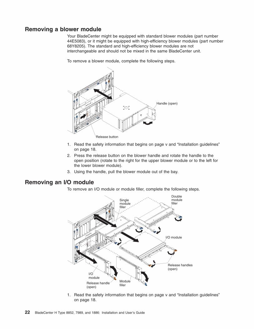
Removing a blower moduleYour BladeCenter might be equipped with standard blower modules (part number44E5083), or it might be equipped with high-efficiency blower modules (part number68Y8205). The standard and high-efficiency blower modules are notinterchangeable and should not be mixed in the same BladeCenter unit.
To remove a blower module, complete the following steps.
Handle (open)
Release button
1. Read the safety information that begins on page v and “Installation guidelines”on page 18.
2. Press the release button on the blower handle and rotate the handle to theopen position (rotate to the right for the upper blower module or to the left forthe lower blower module).
3. Using the handle, pull the blower module out of the bay.
Removing an I/O moduleTo remove an I/O module or module filler, complete the following steps.
I/Omodule
Modulefiller
I/O module
Singlemodulefiller
Doublemodulefiller
Release handles(open)
Release handle(open)
1. Read the safety information that begins on page v and “Installation guidelines”on page 18.
22 BladeCenter H Type 8852, 7989, and 1886: Installation and User’s Guide
2. Pull the release handle or handles to the open position. The module moves outof the bay approximately 0.6 cm (0.25 inch).
Note: The modules and fillers in I/O bays 1 through 6 each have one releasehandle; the modules and fillers in I/O bays 7 through 10 each have two releasehandles.
3. Slide the module out of the bay.
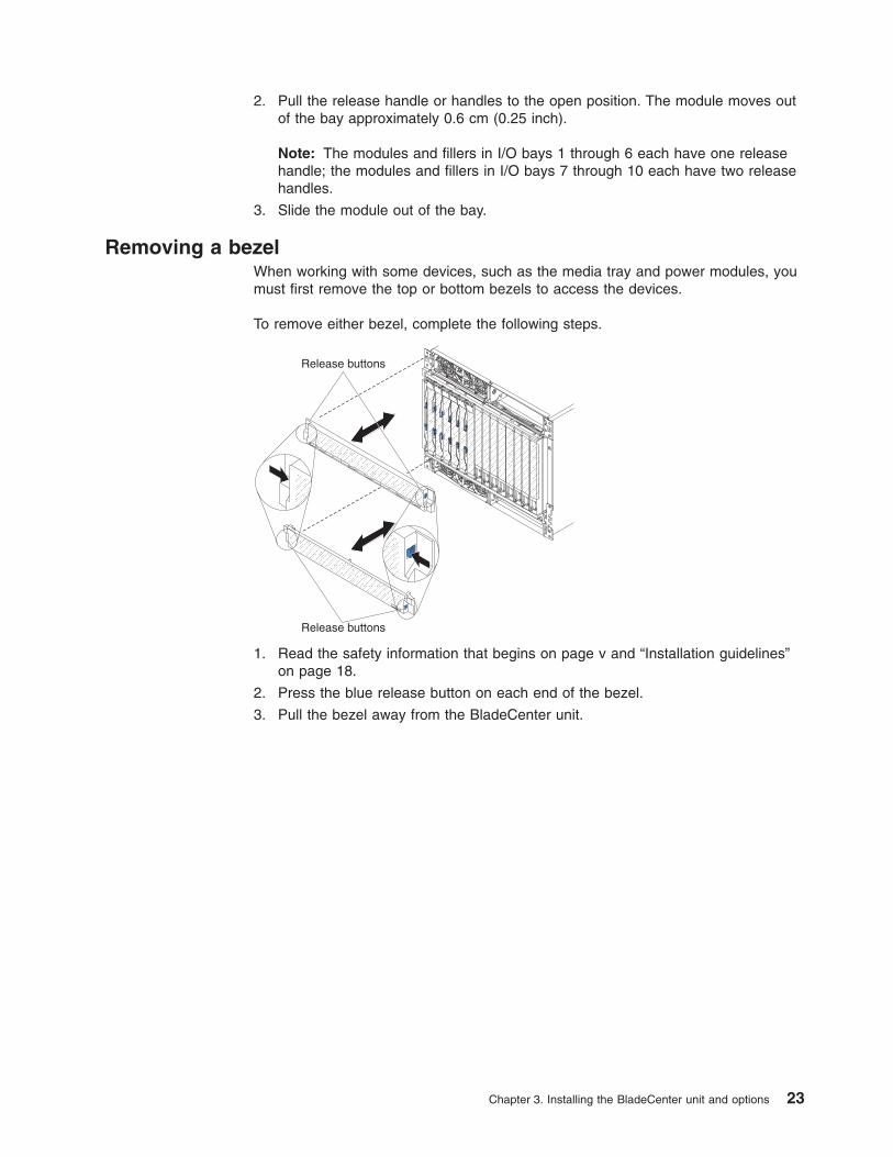
Removing a bezelWhen working with some devices, such as the media tray and power modules, youmust first remove the top or bottom bezels to access the devices.
To remove either bezel, complete the following steps.
Release buttons
Release buttons
1. Read the safety information that begins on page v and “Installation guidelines”on page 18.
2. Press the blue release button on each end of the bezel.
3. Pull the bezel away from the BladeCenter unit.
Chapter 3. Installing the BladeCenter unit and options 23
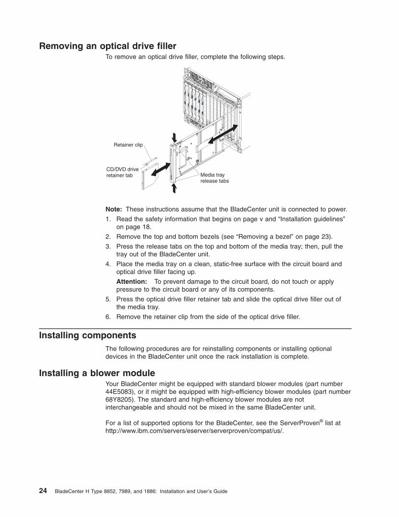
Removing an optical drive fillerTo remove an optical drive filler, complete the following steps.
Media trayrelease tabs
CD/DVD driveretainer tab
Retainer clip
Note: These instructions assume that the BladeCenter unit is connected to power.
1. Read the safety information that begins on page v and “Installation guidelines”on page 18.
2. Remove the top and bottom bezels (see “Removing a bezel” on page 23).
3. Press the release tabs on the top and bottom of the media tray; then, pull thetray out of the BladeCenter unit.
4. Place the media tray on a clean, static-free surface with the circuit board andoptical drive filler facing up.
Attention: To prevent damage to the circuit board, do not touch or applypressure to the circuit board or any of its components.
5. Press the optical drive filler retainer tab and slide the optical drive filler out ofthe media tray.
6. Remove the retainer clip from the side of the optical drive filler.
Installing componentsThe following procedures are for reinstalling components or installing optionaldevices in the BladeCenter unit once the rack installation is complete.
Installing a blower moduleYour BladeCenter might be equipped with standard blower modules (part number44E5083), or it might be equipped with high-efficiency blower modules (part number68Y8205). The standard and high-efficiency blower modules are notinterchangeable and should not be mixed in the same BladeCenter unit.
For a list of supported options for the BladeCenter, see the ServerProven® list athttp://www.ibm.com/servers/eserver/serverproven/compat/us/.
24 BladeCenter H Type 8852, 7989, and 1886: Installation and User’s Guide
Note: Government regulations (such as those prescribed by Occupational Safetyand Health Administration or European Community Directives) might govern noiselevel exposure in the workplace and might apply to you and your server installation.The actual sound pressure levels in your installation depend on a variety of factors,including the number of racks in the installation; the size, materials, andconfiguration of the room where you designate the racks to be installed; the noiselevels from other equipment; the room ambient temperature; and employees'location in relation to the equipment. Compliance with such government regulationsalso depends on a variety of additional factors, including the duration of employees'exposure and whether employees wear hearing protection. It is recommended thatyou consult qualified experts in this field to determine whether you are incompliance with the applicable regulations.
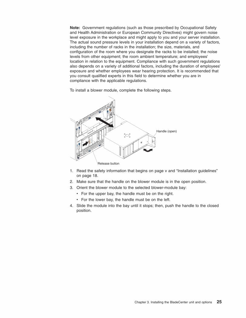
To install a blower module, complete the following steps.
Handle (open)
Release button
1. Read the safety information that begins on page v and “Installation guidelines”on page 18.
2. Make sure that the handle on the blower module is in the open position.
3. Orient the blower module to the selected blower-module bay:
v For the upper bay, the handle must be on the right.
v For the lower bay, the handle must be on the left.
4. Slide the module into the bay until it stops; then, push the handle to the closedposition.
Chapter 3. Installing the BladeCenter unit and options 25
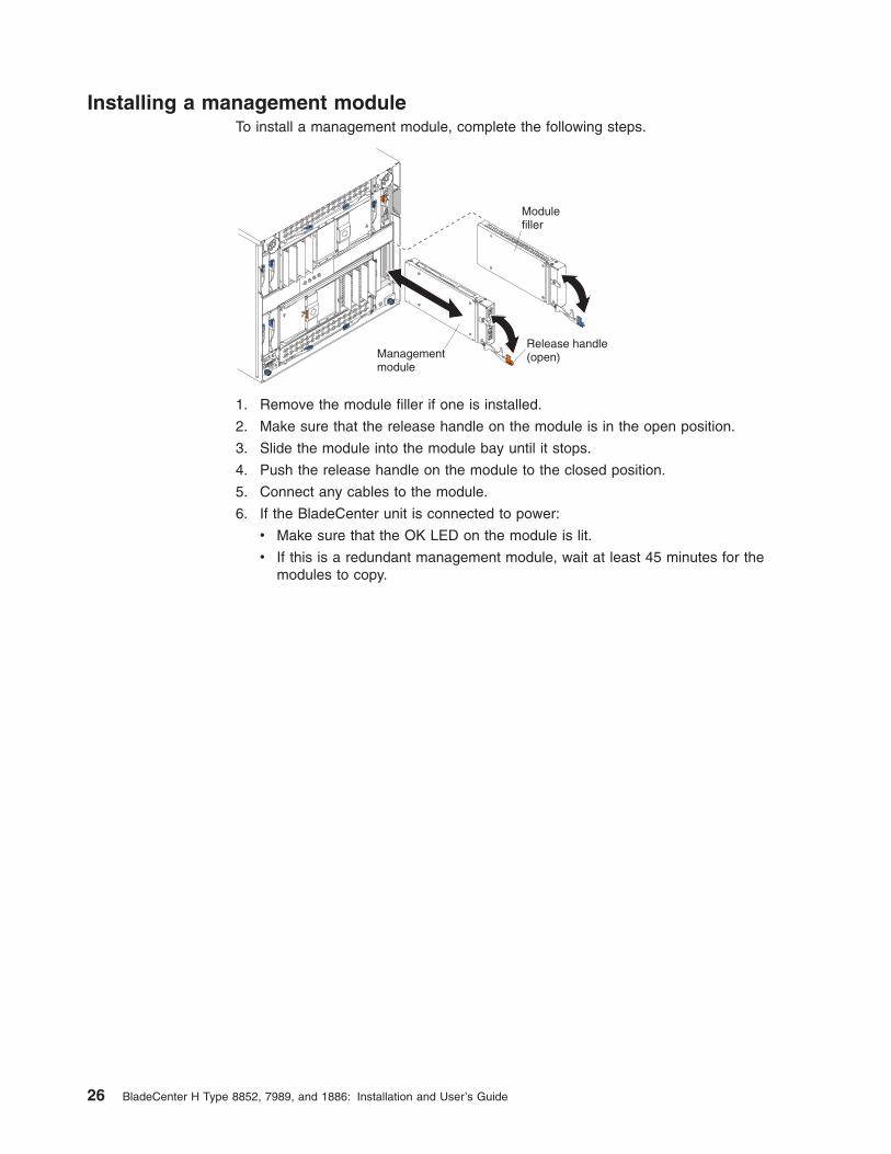
Installing a management moduleTo install a management module, complete the following steps.
Managementmodule
Release handle(open)
Modulefiller
1. Remove the module filler if one is installed.
2. Make sure that the release handle on the module is in the open position.
3. Slide the module into the module bay until it stops.
4. Push the release handle on the module to the closed position.
5. Connect any cables to the module.
6. If the BladeCenter unit is connected to power:
v Make sure that the OK LED on the module is lit.
v If this is a redundant management module, wait at least 45 minutes for themodules to copy.
26 BladeCenter H Type 8852, 7989, and 1886: Installation and User’s Guide
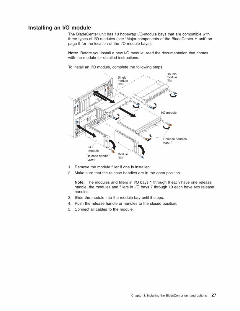
Installing an I/O moduleThe BladeCenter unit has 10 hot-swap I/O-module bays that are compatible withthree types of I/O modules (see “Major components of the BladeCenter H unit” onpage 9 for the location of the I/O module bays).
Note: Before you install a new I/O module, read the documentation that comeswith the module for detailed instructions.
To install an I/O module, complete the following steps.
I/Omodule
Modulefiller
I/O module
Singlemodulefiller
Doublemodulefiller
Release handles(open)
Release handle(open)
1. Remove the module filler if one is installed.
2. Make sure that the release handles are in the open position.
Note: The modules and fillers in I/O bays 1 through 6 each have one releasehandle; the modules and fillers in I/O bays 7 through 10 each have two releasehandles.
3. Slide the module into the module bay until it stops.
4. Push the release handle or handles to the closed position.
5. Connect all cables to the module.
Chapter 3. Installing the BladeCenter unit and options 27
Installing a power moduleTwo types of power modules are supported for your BladeCenter, 2900W powermodules with removable fan pack and 2980W high-efficiency power modules withintegrated fan pack. The IBM 2980-watt power modules for BladeCenter® H aremore efficient than the 2900W power modules, using less power without sacrificingperformance. The 2900W and 2980W high-efficiency power modules are notinterchangeable within the same power domain of the chassis. A power moduleconfiguration is supported only if the two power modules are matched within thesame power domain:
v Power modules 1 and 2 provide power for domain A (blade slots 1 to 7)
v Power modules 3 and 4 provide power for domain B (blade slots 8 to 14)
The following is an example of a supported configuration:
v Domain A: Power Module 1; 2900W, Power Module 2; 2900W
v Domain B: Power Module 3; 2980W, Power Module 4; 2980W
This is an example of a non-supported configuration:
v Domain A: Power Module 1; 2900W, Power Module 2; 2980W
v Domain B: Power Module 3; 2900W, Power Module 4; 2980W
Attention: Failed power modules should only be replaced with the same type ofpower module.
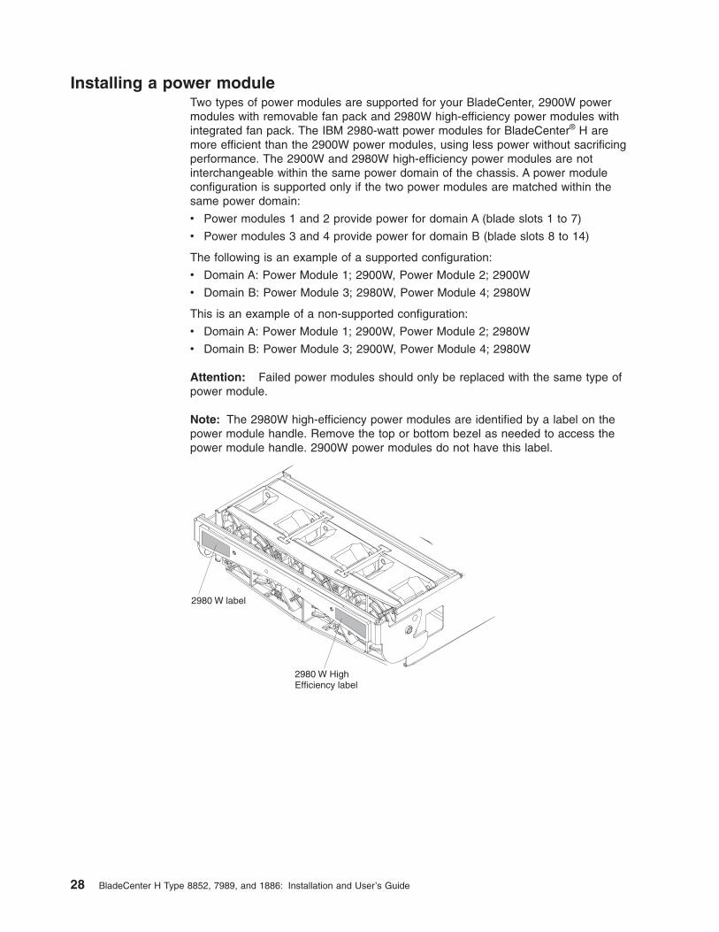
Note: The 2980W high-efficiency power modules are identified by a label on thepower module handle. Remove the top or bottom bezel as needed to access thepower module handle. 2900W power modules do not have this label.
2980 W HighEfficiency label
2980 W label
28 BladeCenter H Type 8852, 7989, and 1886: Installation and User’s Guide
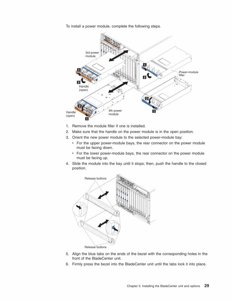
To install a power module, complete the following steps.
3rd powermodule
4th powermodule
Power-modulefiller
Handle(open)
Handle(open)
1. Remove the module filler if one is installed.
2. Make sure that the handle on the power module is in the open position.
3. Orient the new power module to the selected power-module bay:
v For the upper power-module bays, the rear connector on the power modulemust be facing down.
v For the lower power-module bays, the rear connector on the power modulemust be facing up.
4. Slide the module into the bay until it stops; then, push the handle to the closedposition.
Release buttons
Release buttons
5. Align the blue tabs on the ends of the bezel with the corresponding holes in thefront of the BladeCenter unit.
6. Firmly press the bezel into the BladeCenter unit until the tabs lock it into place.
Chapter 3. Installing the BladeCenter unit and options 29

Installing an optical driveTo install an optical drive, complete the following steps.
Media trayrelease tabs
CD/DVD driveretainer tab
Retainer clip
Note: These instructions assume that the BladeCenter unit is connected to power.
1. Remove the media tray and optical drive filler (see “Removing an optical drivefiller” on page 24).
2. Make sure that the media tray is on a clean, static-free surface with the circuitboard facing up.
Attention: To prevent damage to the circuit board, do not touch or applypressure to the circuit board or any of its components.
3. Install the retainer clip on the side of the optical drive.
4. Carefully slide the optical drive into the bay on the media tray until it fullyengages the connector and the retainer tab locks into place.
5. Carefully slide the media tray into the BladeCenter unit until the release tabslock it into place.
6. Install the top and bottom bezels (see “Installing a bezel” on page 31).
30 BladeCenter H Type 8852, 7989, and 1886: Installation and User’s Guide
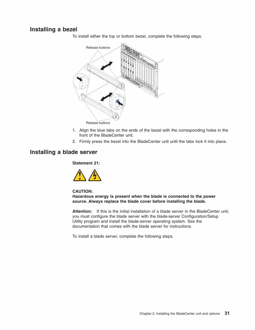
Installing a bezelTo install either the top or bottom bezel, complete the following steps.
Release buttons
Release buttons
1. Align the blue tabs on the ends of the bezel with the corresponding holes in thefront of the BladeCenter unit.
2. Firmly press the bezel into the BladeCenter unit until the tabs lock it into place.
Installing a blade server
Statement 21:
CAUTION:Hazardous energy is present when the blade is connected to the powersource. Always replace the blade cover before installing the blade.
Attention: If this is the initial installation of a blade server in the BladeCenter unit,you must configure the blade server with the blade-server Configuration/SetupUtility program and install the blade-server operating system. See thedocumentation that comes with the blade server for instructions.
To install a blade server, complete the following steps.
Chapter 3. Installing the BladeCenter unit and options 31
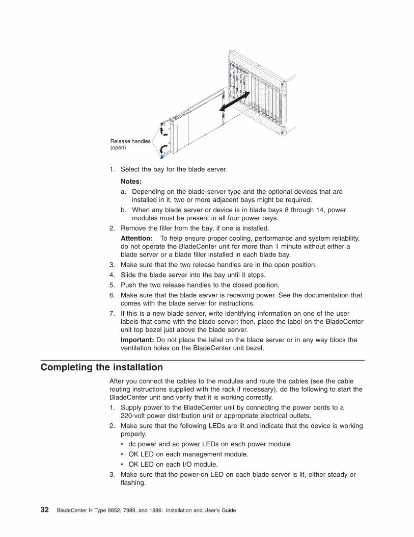
Release handles(open)
1. Select the bay for the blade server.
Notes:
a. Depending on the blade-server type and the optional devices that areinstalled in it, two or more adjacent bays might be required.
b. When any blade server or device is in blade bays 8 through 14, powermodules must be present in all four power bays.
2. Remove the filler from the bay, if one is installed.
Attention: To help ensure proper cooling, performance and system reliability,do not operate the BladeCenter unit for more than 1 minute without either ablade server or a blade filler installed in each blade bay.
3. Make sure that the two release handles are in the open position.
4. Slide the blade server into the bay until it stops.
5. Push the two release handles to the closed position.
6. Make sure that the blade server is receiving power. See the documentation thatcomes with the blade server for instructions.
7. If this is a new blade server, write identifying information on one of the userlabels that come with the blade server; then, place the label on the BladeCenterunit top bezel just above the blade server.
Important: Do not place the label on the blade server or in any way block theventilation holes on the BladeCenter unit bezel.
Completing the installationAfter you connect the cables to the modules and route the cables (see the cablerouting instructions supplied with the rack if necessary), do the following to start theBladeCenter unit and verify that it is working correctly.
1. Supply power to the BladeCenter unit by connecting the power cords to a220-volt power distribution unit or appropriate electrical outlets.
2. Make sure that the following LEDs are lit and indicate that the device is workingproperly.
v dc power and ac power LEDs on each power module.
v OK LED on each management module.
v OK LED on each I/O module.
3. Make sure that the power-on LED on each blade server is lit, either steady orflashing.
32 BladeCenter H Type 8852, 7989, and 1886: Installation and User’s Guide
See Chapter 2, “BladeCenter unit power, controls, and indicators,” on page 11 forinformation about the location of the LEDs on the modules. See the documentationthat comes with the blade servers for the location of the LEDs on the blade servers.
Chapter 3. Installing the BladeCenter unit and options 33

34 BladeCenter H Type 8852, 7989, and 1886: Installation and User’s Guide
Chapter 4. Configuration and networking guidelines
The BladeCenter components are configured and managed through a managementmodule. Depending on your management module type, you can configure themanagement module and the BladeCenter unit components through a local orremote connection and management-module user interfaces or other systemmanagement tools. See your management-module documentation for instructionsfor configuring the BladeCenter unit.
Configuring the BladeCenter unitGeneral configuration of the BladeCenter unit and installed components isperformed through the management module. See the BladeCenter ManagementModule User’s Guide and the BladeCenter Management Module Command-LineInterface Reference Guide for your management module for information andinstructions. Some devices in the BladeCenter unit, such as I/O modules and bladeservers, might also require additional configuration. See the documentation thatcomes with each device for information and instructions.
Configuring the management moduleAll management modules preconfigured with the same static IP address. You canuse the management module to assign a new static IP address. To establishconnectivity, the management module attempts to use Dynamic Host ConfigurationProtocol (DHCP) to acquire its initial IP address for the management-moduleEthernet port. If DHCP is not installed or is enabled and fails, the managementmodule uses the static IP address. Use the management module to configure otherBladeCenter component settings, such as user accounts, DHCP, or Wake on LAN.See the documentation for your management module for instructions.
Configuring I/O modulesYou must install and configure at least one external (in-band) port on an Ethernetswitch module in I/O-module bay 1 or 2 to communicate with the Ethernetcontrollers that are integrated in each blade server. See the documentation for yourmanagement module for information about configuring external ports on I/Omodules. For I/O-device settings, see the documentation that comes with your I/Odevice.
Note: If a pass-thru module is installed in I/O-module bay 1 or 2, you mustconfigure the network switch that the pass-thru module is connected to; see thedocumentation that comes with the network switch.
Configuring blade serversTo achieve blade-server redundancy, you must configure the Ethernet controllers inone or more blade servers for failover. When failover occurs on a blade server, thesecondary Ethernet controller takes over network communications, using the I/Omodule that is associated with that controller. Install a pair of Ethernet switches inI/O-module bays 1 and 2, and then configure them and your network infrastructureso that they can direct traffic to the same destinations. You can also install apass-thru module that is connected to an external Ethernet switch in either or bothof these I/O-module bays. See the documentation that comes with your bladeserver and operating system for instructions.
© Copyright IBM Corp. 2012 35
Using IBM FastSetupIBM FastSetup is a no-cost software tool that helps simplify the maintenance anddeployment of selected IBM BladeCenter chassis, servers, and components. Theintuitive graphical interface initializes all phases of server setup, including discovery,update, and configuration. Features include templates that enable replication ofsettings to many servers and automation that reduces hands-on time and usererrors. Wizards and other default settings enable customization capabilities. Thelow-touch, set-once and walk-away feature reduces the hands-on server setup timefrom days to minutes, particularly for larger deployments. For information about thistool, see http://www.ibm.com/support/entry/portal/docdisplay?brand=5000008&lndocid=TOOL-FASTSET.
BladeCenter networking guidelinesMake sure the network infrastructure is configured before you connect theBladeCenter unit to a LAN switch or similar network device.
Each blade server has two independent Ethernet controllers, each with its ownMAC address and a dedicated 1000-Mbps link to one of the switch modules in I/Omodule bays 1 and 2. There is no internal data path between the two switcheswithin the BladeCenter unit; an external network device is required for data packetsto flow from one internal switch to the other.
The management module has a separate internal 100-Mbps link to each switch.These links are for internal management and control only. No data packets areallowed to flow from application programs on the blade servers to the managementmodule over this path.
36 BladeCenter H Type 8852, 7989, and 1886: Installation and User’s Guide
Chapter 5. IBM Director
This chapter provides information about IBM Director, a workgroup-hardware-management tool that you can use to centrally manage IBM servers.
With IBM Director, a network administrator can perform the following tasks:
v View the hardware configuration of remote systems, in detail.
v Monitor the usage and performance of critical components, such asmicroprocessors, disks, and memory.
v Centrally manage individual or large groups of IBM and non-IBMIntel-processor-based servers, desktop computers, workstations, and mobilecomputers on a variety of platforms.
IBM Director provides a comprehensive entry-level workgroup hardware manager. Itincludes the following key features:
v Advanced self-management capabilities for maximum system availability.
v Multiple operating-system platform support, including Microsoft Windows 2000Server, Windows XP Professional, Red Hat Linux, SUSE Linux, and NovellNetWare. For a complete list of operating systems that support IBM Director, seethe IBM Director Compatibility Document. This document is in PDF athttp://www.ibm.com/servers/eserver/xseries/systems_management/sys_migration/ibmdiragent.html. It is updated every 6 to 8 weeks.
v Support for IBM and non-IBM servers, desktop computers, workstations, andmobile computers.
v Support for systems-management industry standards.
v Integration into leading workgroup and enterprise systems-managementenvironments.
v Ease of use, training, and setup.
IBM Director also provides an extensible platform that supports advancedBladeCenter tools that are designed to reduce the total cost of managing andsupporting networked systems. By deploying IBM Director, you can achievereductions in ownership costs through the following benefits:v Reduced downtimev Increased productivity of IT personnel and usersv Reduced service and support costs
For more information about IBM Director, see the documentation on the IBMDirector CD that comes with the BladeCenter unit, the IBM Director InformationCenter at http://publib.boulder.ibm.com/infocenter/eserver/ v1r2/topic/diricinfo/fgm0_main.htm, and the IBM System x Management Web page athttp://www.ibm.com/servers/eserver/ xseries/systems_management/xseries_sm.html,which present an overview of IBM Systems Management and IBM Director.
© Copyright IBM Corp. 2012 37

38 BladeCenter H Type 8852, 7989, and 1886: Installation and User’s Guide
Chapter 6. Shared BladeCenter resources
The BladeCenter unit provides resources that are available to most blade servers atall times, such as power modules, cooling, system management, and network I/Omodules; no user intervention is required. Some resources are selectable for use bya single blade server at a time, such as the media tray or the keyboard-video-mouse (KVM). You can select the resources for a blade server in the followingways:
Attention: Do not switch ownership of the media tray to another blade serverwhile a transaction is taking place on the optical drive or an attached USB device.The data might become corrupted. Make sure that activity lights on the optical driveare not lit.
v Most blade servers have two selection buttons on the front of the blade server
CD and .
v You can use the management-module Web interface to enable or disable theselect buttons on the blade servers and change ownership of the media tray orthe KVM (Blade Tasks → Remote Control).
The monitor that is attached to the management module shows the video outputfrom the blade server that is the current owner of the KVM. When there is noactively selected video from any blade server, the video from blade server 14 isrouted to the management module. While the management module is restarting,there is temporarily no current KVM owner. The video from blade server 14 isdisplayed on the monitor briefly until the management module uses its NVRAMvalues to reestablish ownership of the KVM and media tray (optical drive,diskette drive, and front panel USB ports). After that, the video from the bladeserver that is the current KVM owner is displayed on the monitor.
– To switch the KVM to a specific blade server, press the button on thatblade server.
– To switch the media tray to a specific blade server, press the CD button onthat blade server.
The management module assigns the resource to the blade server that isrequesting it.
v On a keyboard that is directly attached to the management module, you canpress keyboard keys in the following sequence to switch KVM control betweenblade servers:
NumLock NumLock blade_server_number Enter
Where blade_server_number is the two-digit number for the blade bay in whichthe blade server is installed. When using some keyboards, such as the 28L3644(37L0888) keyboard, you must hold down the Shift key while you enter this keysequence.
It can take up to 20 seconds for the operating system in the switched-to bladeserver to recognize the media tray or the KVM. If you install Microsoft Windows2000 on a blade server while it is not the current owner of the media tray or theKVM, the first time the blade server requests ownership after the operating systemhas been installed, it can take up to 1 minute for the operating system to recognizethe devices (this is a one-time-only occurrence).
© Copyright IBM Corp. 2012 39

Note: The operating system in the blade server must provide USB support for theblade server to recognize and use the media tray. The BladeCenter unit uses USBfor internal communication with these devices.
40 BladeCenter H Type 8852, 7989, and 1886: Installation and User’s Guide
Chapter 7. Solving problems
This section provides basic troubleshooting information to help you solve somecommon problems that might occur while you are setting up your BladeCenter unit.
If you cannot locate and correct the problem using the information in this section,see the Problem Determination and Service Guide for more information.
Diagnostic tools overviewThe following tools are available to help you diagnose and solve hardware-relatedproblems:
v Troubleshooting tables
These tables list problem symptoms and steps to correct the problems. See“Troubleshooting tables” for more information.
v Diagnostic programs and error messages
The built-in self-test (BIST) program checks the BladeCenter unit during startupand generates error messages if problems are found.
v Light path diagnostic LEDs
Use the light path diagnostic LEDs on the BladeCenter unit and the BladeCentercomponents to identify system errors quickly. See “Light path diagnostic LEDs”on page 44.
Troubleshooting tablesUse the troubleshooting tables to find solutions to problems that have identifiablesymptoms.
Note: The symptoms for monitor, keyboard, and mouse apply only to the devicesthat are connected to the management module; they do not apply to the remoteconsole.
See the Problem Determination and Service Guide for more detailed informationabout testing the BladeCenter unit. If you have run the diagnostic test programs orif running the tests does not reveal the cause of problem, call for service.
Attention: If diagnostic error messages appear that are not listed in the ProblemDetermination and Service Guide, make sure that the latest level of firmware codeis installed in your BladeCenter unit.
If you have just added a new optional device and your system is not working,complete the following procedure before using the troubleshooting tables:
1. Remove the device that you just added.
2. Run the diagnostic tests to determine whether the system is running correctly.
3. Reinstall the new device.
© Copyright IBM Corp. 2012 41
Monitor or video problems
Note: These symptoms apply only to the monitor that is connected to themanagement module; they do not apply to the remote console.
Some IBM monitors have their own self-tests. If you suspect a problem with yourmonitor, see the documentation that comes with the monitor for instructions fortesting and adjusting the monitor.
v Follow the suggested actions in the order in which they are listed in the Action column until the problemis solved.
v If an action step is preceded by “(Trained service technician only),” that step must be performed only by atrained service technician.
Symptom Action
The monitor is not working 1. Make sure that:
v The monitor is turned on and the brightness and contrast controls areadjusted correctly.
v The monitor is connected to the active management module.
v The blade server that owns the KVM is turned on.
v The KVM is owned by a blade server that supports KVM.
2. Reseat the monitor cable.
3. Replace the monitor.
Power problems
v Follow the suggested actions in the order in which they are listed in the Action column until the problemis solved.
v If an action step is preceded by “(Trained service technician only),” that step must be performed only by atrained service technician.
Symptom Action
The BladeCenter unit does notpower on.
1. Make sure that:
a. All power cords are plugged into 220-Volt power sources and that thepower sources are working.
b. The ac power and dc power LEDs on the power modules are lit.
2. If you just installed an option, remove it, and restart the BladeCenter unit. If theBladeCenter unit now powers on, you might have installed more options thanthe power modules support. You might have to install power modules inpower-module bays 3 and 4.
3. If the problem remains, see the BladeCenter H Problem Determination andService Guide for more information.
42 BladeCenter H Type 8852, 7989, and 1886: Installation and User’s Guide
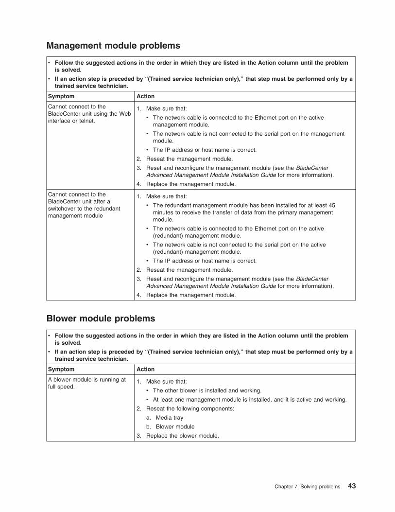
Management module problems
v Follow the suggested actions in the order in which they are listed in the Action column until the problemis solved.
v If an action step is preceded by “(Trained service technician only),” that step must be performed only by atrained service technician.
Symptom Action
Cannot connect to theBladeCenter unit using the Webinterface or telnet.
1. Make sure that:
v The network cable is connected to the Ethernet port on the activemanagement module.
v The network cable is not connected to the serial port on the managementmodule.
v The IP address or host name is correct.
2. Reseat the management module.
3. Reset and reconfigure the management module (see the BladeCenterAdvanced Management Module Installation Guide for more information).
4. Replace the management module.
Cannot connect to theBladeCenter unit after aswitchover to the redundantmanagement module
1. Make sure that:
v The redundant management module has been installed for at least 45minutes to receive the transfer of data from the primary managementmodule.
v The network cable is connected to the Ethernet port on the active(redundant) management module.
v The network cable is not connected to the serial port on the active(redundant) management module.
v The IP address or host name is correct.
2. Reseat the management module.
3. Reset and reconfigure the management module (see the BladeCenterAdvanced Management Module Installation Guide for more information).
4. Replace the management module.
Blower module problems
v Follow the suggested actions in the order in which they are listed in the Action column until the problemis solved.
v If an action step is preceded by “(Trained service technician only),” that step must be performed only by atrained service technician.
Symptom Action
A blower module is running atfull speed.
1. Make sure that:
v The other blower is installed and working.
v At least one management module is installed, and it is active and working.
2. Reseat the following components:
a. Media tray
b. Blower module
3. Replace the blower module.
Chapter 7. Solving problems 43
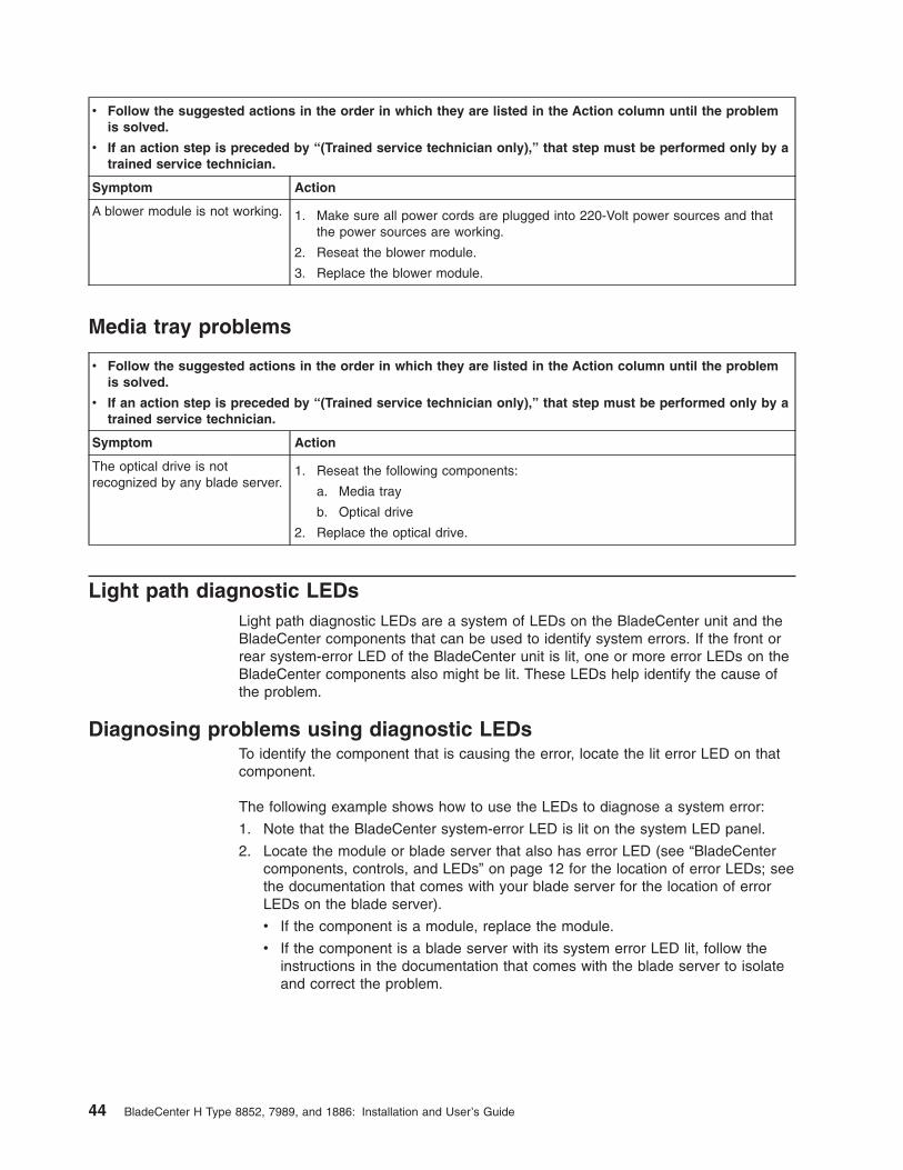
v Follow the suggested actions in the order in which they are listed in the Action column until the problemis solved.
v If an action step is preceded by “(Trained service technician only),” that step must be performed only by atrained service technician.
Symptom Action
A blower module is not working. 1. Make sure all power cords are plugged into 220-Volt power sources and thatthe power sources are working.
2. Reseat the blower module.
3. Replace the blower module.
Media tray problems
v Follow the suggested actions in the order in which they are listed in the Action column until the problemis solved.
v If an action step is preceded by “(Trained service technician only),” that step must be performed only by atrained service technician.
Symptom Action
The optical drive is notrecognized by any blade server.
1. Reseat the following components:
a. Media tray
b. Optical drive
2. Replace the optical drive.
Light path diagnostic LEDsLight path diagnostic LEDs are a system of LEDs on the BladeCenter unit and theBladeCenter components that can be used to identify system errors. If the front orrear system-error LED of the BladeCenter unit is lit, one or more error LEDs on theBladeCenter components also might be lit. These LEDs help identify the cause ofthe problem.
Diagnosing problems using diagnostic LEDsTo identify the component that is causing the error, locate the lit error LED on thatcomponent.
The following example shows how to use the LEDs to diagnose a system error:
1. Note that the BladeCenter system-error LED is lit on the system LED panel.
2. Locate the module or blade server that also has error LED (see “BladeCentercomponents, controls, and LEDs” on page 12 for the location of error LEDs; seethe documentation that comes with your blade server for the location of errorLEDs on the blade server).
v If the component is a module, replace the module.
v If the component is a blade server with its system error LED lit, follow theinstructions in the documentation that comes with the blade server to isolateand correct the problem.
44 BladeCenter H Type 8852, 7989, and 1886: Installation and User’s Guide
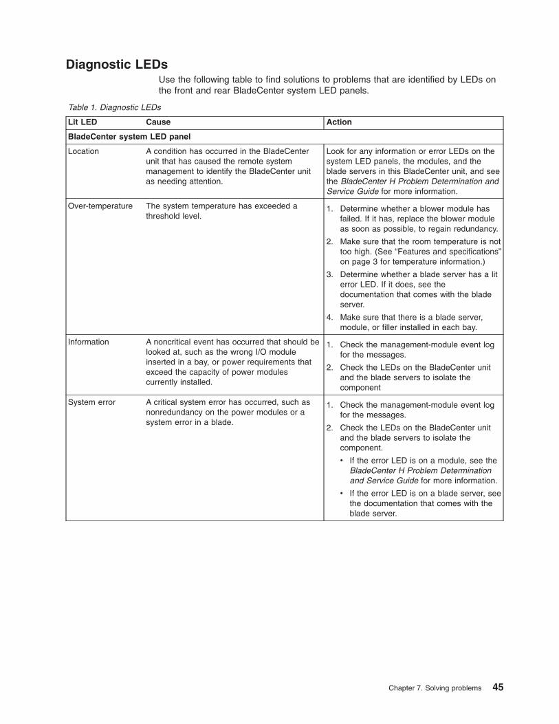
Diagnostic LEDsUse the following table to find solutions to problems that are identified by LEDs onthe front and rear BladeCenter system LED panels.
Table 1. Diagnostic LEDs
Lit LED Cause Action
BladeCenter system LED panel
Location A condition has occurred in the BladeCenterunit that has caused the remote systemmanagement to identify the BladeCenter unitas needing attention.
Look for any information or error LEDs on thesystem LED panels, the modules, and theblade servers in this BladeCenter unit, and seethe BladeCenter H Problem Determination andService Guide for more information.
Over-temperature The system temperature has exceeded athreshold level.
1. Determine whether a blower module hasfailed. If it has, replace the blower moduleas soon as possible, to regain redundancy.
2. Make sure that the room temperature is nottoo high. (See “Features and specifications”on page 3 for temperature information.)
3. Determine whether a blade server has a literror LED. If it does, see thedocumentation that comes with the bladeserver.
4. Make sure that there is a blade server,module, or filler installed in each bay.
Information A noncritical event has occurred that should belooked at, such as the wrong I/O moduleinserted in a bay, or power requirements thatexceed the capacity of power modulescurrently installed.
1. Check the management-module event logfor the messages.
2. Check the LEDs on the BladeCenter unitand the blade servers to isolate thecomponent
System error A critical system error has occurred, such asnonredundancy on the power modules or asystem error in a blade.
1. Check the management-module event logfor the messages.
2. Check the LEDs on the BladeCenter unitand the blade servers to isolate thecomponent.
v If the error LED is on a module, see theBladeCenter H Problem Determinationand Service Guide for more information.
v If the error LED is on a blade server, seethe documentation that comes with theblade server.
Chapter 7. Solving problems 45

46 BladeCenter H Type 8852, 7989, and 1886: Installation and User’s Guide
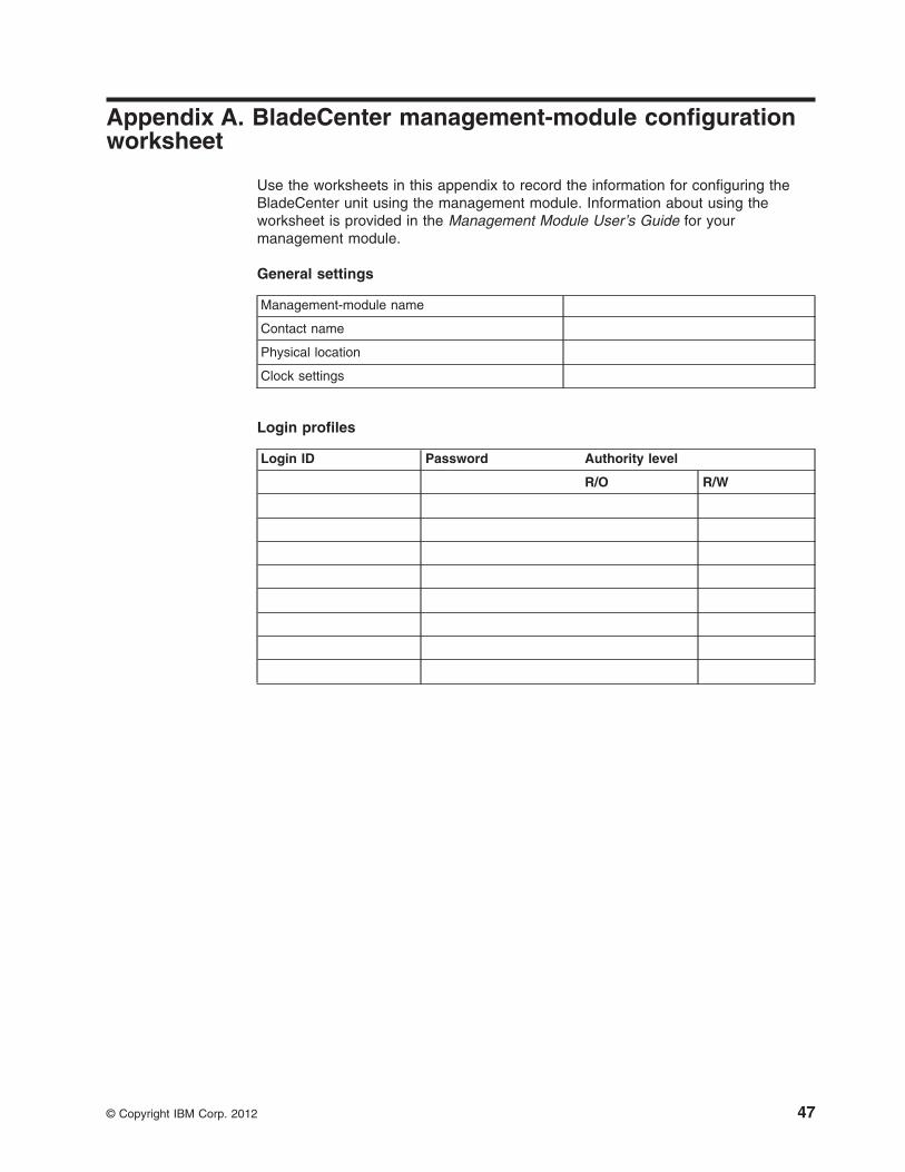
Appendix A. BladeCenter management-module configurationworksheet
Use the worksheets in this appendix to record the information for configuring theBladeCenter unit using the management module. Information about using theworksheet is provided in the Management Module User’s Guide for yourmanagement module.
General settings
Management-module name
Contact name
Physical location
Clock settings
Login profiles
Login ID Password Authority level
R/O R/W
© Copyright IBM Corp. 2012 47
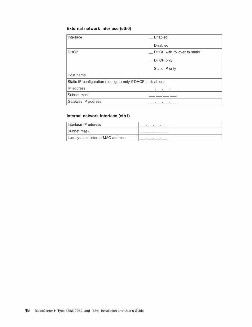
External network interface (eth0)
Interface __ Enabled
__ Disabled
DHCP __ DHCP with rollover to static
__ DHCP only
__ Static IP only
Host name
Static IP configuration (configure only if DHCP is disabled)
IP address ___.___.___.___
Subnet mask ___.___.___.___
Gateway IP address ___.___.___.___
Internal network interface (eth1)
Interface IP address ___.___.___.___
Subnet mask ___.___.___.___
Locally administered MAC address ___.___.___.___
48 BladeCenter H Type 8852, 7989, and 1886: Installation and User’s Guide
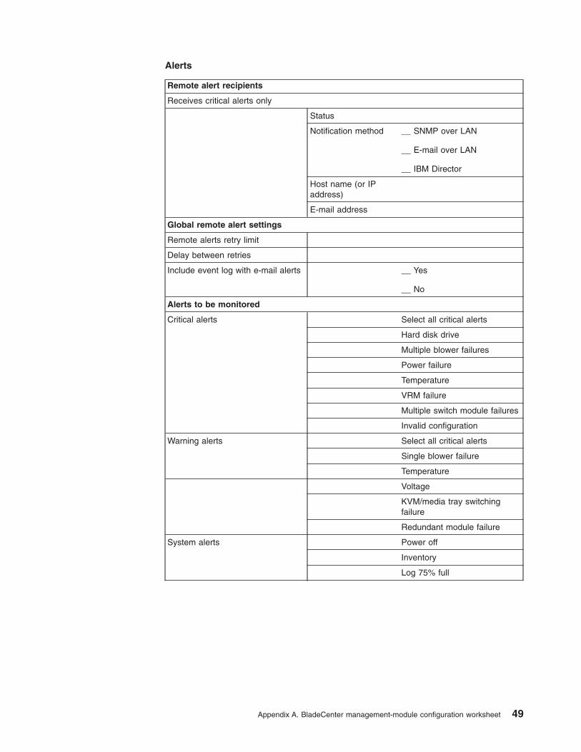
Alerts
Remote alert recipients
Receives critical alerts only
Status
Notification method __ SNMP over LAN
__ E-mail over LAN
__ IBM Director
Host name (or IPaddress)
E-mail address
Global remote alert settings
Remote alerts retry limit
Delay between retries
Include event log with e-mail alerts __ Yes
__ No
Alerts to be monitored
Critical alerts Select all critical alerts
Hard disk drive
Multiple blower failures
Power failure
Temperature
VRM failure
Multiple switch module failures
Invalid configuration
Warning alerts Select all critical alerts
Single blower failure
Temperature
Voltage
KVM/media tray switchingfailure
Redundant module failure
System alerts Power off
Inventory
Log 75% full
Appendix A. BladeCenter management-module configuration worksheet 49
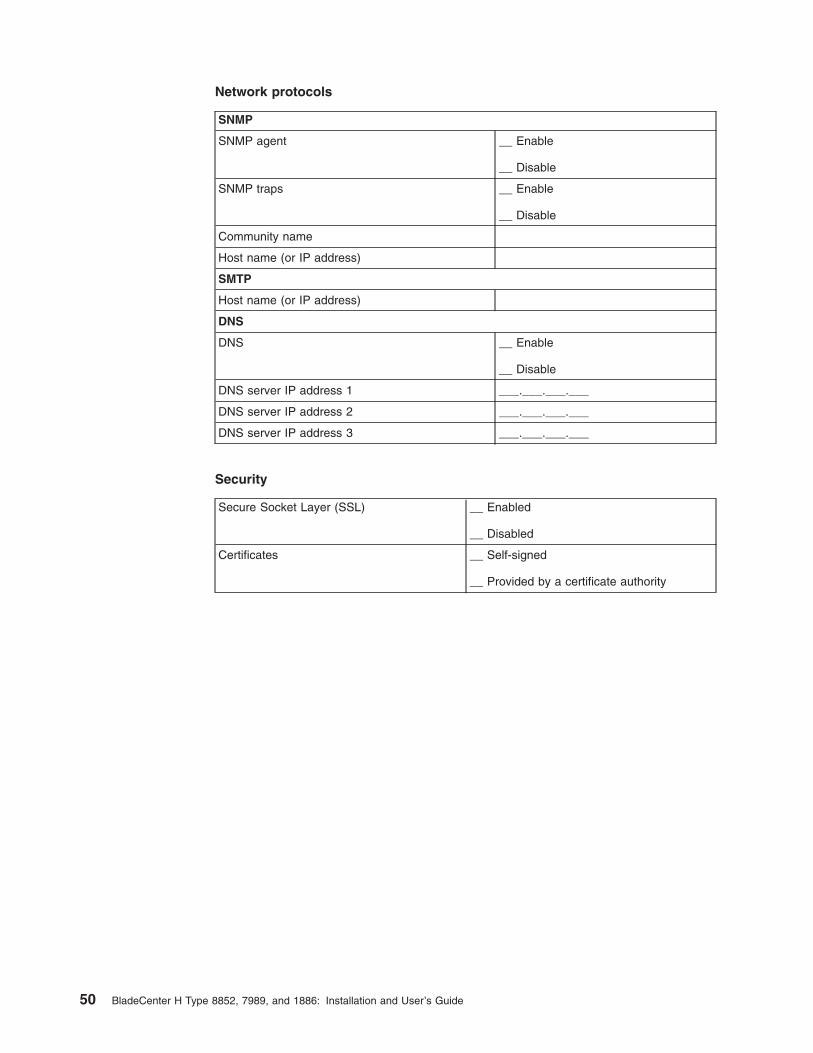
Network protocols
SNMP
SNMP agent __ Enable
__ Disable
SNMP traps __ Enable
__ Disable
Community name
Host name (or IP address)
SMTP
Host name (or IP address)
DNS
DNS __ Enable
__ Disable
DNS server IP address 1 ___.___.___.___
DNS server IP address 2 ___.___.___.___
DNS server IP address 3 ___.___.___.___
Security
Secure Socket Layer (SSL) __ Enabled
__ Disabled
Certificates __ Self-signed
__ Provided by a certificate authority
50 BladeCenter H Type 8852, 7989, and 1886: Installation and User’s Guide

Appendix B. Getting help and technical assistance
If you need help, service, or technical assistance or just want more informationabout IBM products, you will find a wide variety of sources available from IBM toassist you. Use this information to obtain additional information about IBM and IBMproducts, determine what to do if you experience a problem with your IBM systemor optional device, and determine whom to call for service, if it is necessary.
Before you callBefore you call, make sure that you have taken these steps to try to solve theproblem yourself:
v Check all cables to make sure that they are connected.
v Check the power switches to make sure that the system and any optionaldevices are turned on.
v Check for updated firmware and operating-system device drivers for your IBMproduct. The IBM Warranty terms and conditions state that you, the owner of theIBM product, are responsible for maintaining and updating all software andfirmware for the product (unless it is covered by an additional maintenancecontract). Your IBM service technician will request that you upgrade yoursoftware and firmware if the problem has a documented solution within asoftware upgrade.
v If you have installed new hardware or software in your environment, checkhttp://www.ibm.com/systems/info/x86servers/serverproven/compat/us/ to makesure that the hardware and software is supported by your IBM product.
v Go to http://www.ibm.com/supportportal/ to check for information to help yousolve the problem.
v Gather the following information to provide to IBM Support. This data will helpIBM Support quickly provide a solution to your problem and ensure that youreceive the level of service for which you might have contracted.
– Hardware and Software Maintenance agreement contract numbers, ifapplicable
– Machine type number (IBM 4-digit machine identifier)
– Model number
– Serial number
– Current system UEFI and firmware levels
– Other pertinent information such as error messages and logs
v Go to http://www.ibm.com/support/entry/portal/Open_service_request/ to submitan Electronic Service Request. Submitting an Electronic Service Request willstart the process of determining a solution to your problem by making thepertinent information available to IBM Support quickly and efficiently. IBM servicetechnicians can start working on your solution as soon as you have completedand submitted an Electronic Service Request.
You can solve many problems without outside assistance by following thetroubleshooting procedures that IBM provides in the online help or in thedocumentation that is provided with your IBM product. The documentation thatcomes with IBM systems also describes the diagnostic tests that you can perform.Most systems, operating systems, and programs come with documentation that
© Copyright IBM Corp. 2012 51
contains troubleshooting procedures and explanations of error messages and errorcodes. If you suspect a software problem, see the documentation for the operatingsystem or program.
Using the documentationInformation about your IBM system and preinstalled software, if any, or optionaldevice is available in the documentation that comes with the product. Thatdocumentation can include printed documents, online documents, readme files, andhelp files. See the troubleshooting information in your system documentation forinstructions for using the diagnostic programs. The troubleshooting information orthe diagnostic programs might tell you that you need additional or updated devicedrivers or other software. IBM maintains pages on the World Wide Web where youcan get the latest technical information and download device drivers and updates.To access these pages, go to http://www.ibm.com/supportportal/. Also, somedocuments are available through the IBM Publications Center athttp://www.ibm.com/shop/publications/order/.
Getting help and information from the World Wide WebOn the World Wide Web, up-to-date information about IBM systems, optionaldevices, services, and support is available at http://www.ibm.com/supportportal/.The address for IBM System x® information is http://www.ibm.com/systems/x/. Theaddress for IBM BladeCenter information is http://www.ibm.com/systems/bladecenter/. The address for IBM IntelliStation® information ishttp://www.ibm.com/systems/intellistation/.
How to send Dynamic System Analysis data to IBMUse the IBM Enhanced Customer Data Repository to send diagnostic data to IBM.Before you send diagnostic data to IBM, read the terms of use athttp://www.ibm.com/de/support/ecurep/terms.html.
You can use any of the following methods to send diagnostic data to IBM:
v Standard upload: http://www.ibm.com/de/support/ecurep/send_http.html
v Standard upload with the system serial number: http://www.ecurep.ibm.com/app/upload_hw
v Secure upload: http://www.ibm.com/de/support/ecurep/send_http.html#secure
v Secure upload with the system serial number: https://www.ecurep.ibm.com/app/upload_hw
Creating a personalized support web pageAt http://www.ibm.com/support/mynotifications/, you can create a personalizedsupport web page by identifying IBM products that are of interest to you. From thispersonalized page, you can subscribe to weekly email notifications about newtechnical documents, search for information and downloads, and access variousadministrative services.
Software service and supportThrough IBM Support Line, you can get telephone assistance, for a fee, with usage,configuration, and software problems with your IBM products. For information aboutwhich products are supported by Support Line in your country or region, seehttp://www.ibm.com/services/supline/products/.
52 BladeCenter H Type 8852, 7989, and 1886: Installation and User’s Guide
For more information about Support Line and other IBM services, seehttp://www.ibm.com/services/, or see http://www.ibm.com/planetwide/ for supporttelephone numbers. In the U.S. and Canada, call 1-800-IBM-SERV(1-800-426-7378).
Hardware service and supportYou can receive hardware service through your IBM reseller or IBM Services. Tolocate a reseller authorized by IBM to provide warranty service, go tohttp://www.ibm.com/partnerworld/ and click Find Business Partners on the rightside of the page. For IBM support telephone numbers, see http://www.ibm.com/planetwide/. In the U.S. and Canada, call 1-800-IBM-SERV (1-800-426-7378).
In the U.S. and Canada, hardware service and support is available 24 hours a day,7 days a week. In the U.K., these services are available Monday through Friday,from 9 a.m. to 6 p.m.
IBM Taiwan product service
IBM Taiwan product service contact information:IBM Taiwan Corporation3F, No 7, Song Ren Rd.Taipei, TaiwanTelephone: 0800-016-888
Appendix B. Getting help and technical assistance 53

54 BladeCenter H Type 8852, 7989, and 1886: Installation and User’s Guide
Appendix C. Notices
This information was developed for products and services offered in the U.S.A.
IBM may not offer the products, services, or features discussed in this document inother countries. Consult your local IBM representative for information on theproducts and services currently available in your area. Any reference to an IBMproduct, program, or service is not intended to state or imply that only that IBMproduct, program, or service may be used. Any functionally equivalent product,program, or service that does not infringe any IBM intellectual property right may beused instead. However, it is the user's responsibility to evaluate and verify theoperation of any non-IBM product, program, or service.
IBM may have patents or pending patent applications covering subject matterdescribed in this document. The furnishing of this document does not give you anylicense to these patents. You can send license inquiries, in writing, to:
IBM Director of LicensingIBM CorporationNorth Castle DriveArmonk, NY 10504-1785U.S.A.
INTERNATIONAL BUSINESS MACHINES CORPORATION PROVIDES THISPUBLICATION “AS IS” WITHOUT WARRANTY OF ANY KIND, EITHER EXPRESSOR IMPLIED, INCLUDING, BUT NOT LIMITED TO, THE IMPLIED WARRANTIESOF NON-INFRINGEMENT, MERCHANTABILITY OR FITNESS FOR APARTICULAR PURPOSE. Some states do not allow disclaimer of express orimplied warranties in certain transactions, therefore, this statement may not apply toyou.
This information could include technical inaccuracies or typographical errors.Changes are periodically made to the information herein; these changes will beincorporated in new editions of the publication. IBM may make improvements and/orchanges in the product(s) and/or the program(s) described in this publication at anytime without notice.
Any references in this information to non-IBM websites are provided forconvenience only and do not in any manner serve as an endorsement of thosewebsites. The materials at those websites are not part of the materials for this IBMproduct, and use of those websites is at your own risk.
IBM may use or distribute any of the information you supply in any way it believesappropriate without incurring any obligation to you.
TrademarksIBM, the IBM logo, and ibm.com are trademarks of International Business MachinesCorp., registered in many jurisdictions worldwide. Other product and service namesmight be trademarks of IBM or other companies. A current list of IBM trademarks isavailable on the web at “Copyright and trademark information” athttp://www.ibm.com/legal/copytrade.shtml.
Adobe and PostScript are either registered trademarks or trademarks of AdobeSystems Incorporated in the United States and/or other countries.
© Copyright IBM Corp. 2012 55

Cell Broadband Engine is a trademark of Sony Computer Entertainment, Inc., in theUnited States, other countries, or both and is used under license therefrom.
Intel, Intel Xeon, Itanium, and Pentium are trademarks or registered trademarks ofIntel Corporation or its subsidiaries in the United States and other countries.
Java and all Java-based trademarks and logos are trademarks or registeredtrademarks of Oracle and/or its affiliates.
Linux is a registered trademark of Linus Torvalds in the United States, othercountries, or both.
Microsoft, Windows, and Windows NT are trademarks of Microsoft Corporation inthe United States, other countries, or both.
UNIX is a registered trademark of The Open Group in the United States and othercountries.
Important notesProcessor speed indicates the internal clock speed of the microprocessor; otherfactors also affect application performance.
CD or DVD drive speed is the variable read rate. Actual speeds vary and are oftenless than the possible maximum.
When referring to processor storage, real and virtual storage, or channel volume,KB stands for 1024 bytes, MB stands for 1,048,576 bytes, and GB stands for1,073,741,824 bytes.
When referring to hard disk drive capacity or communications volume, MB standsfor 1,000,000 bytes, and GB stands for 1,000,000,000 bytes. Total user-accessiblecapacity can vary depending on operating environments.
Maximum internal hard disk drive capacities assume the replacement of anystandard hard disk drives and population of all hard disk drive bays with the largestcurrently supported drives that are available from IBM.
Maximum memory might require replacement of the standard memory with anoptional memory module.
Each solid-state memory cell has an intrinsic, finite number of write cycles that thecell can incur. Therefore, a solid-state device has a maximum number of writecycles that it can be subjected to, expressed as “total bytes written” (TBW). Adevice that has exceeded this limit might fail to respond to system-generatedcommands or might be incapable of being written to. IBM is not responsible forreplacement of a device that has exceeded its maximum guaranteed number ofprogram/erase cycles, as documented in the Official Published Specifications for thedevice.
IBM makes no representation or warranties regarding non-IBM products andservices that are ServerProven®, including but not limited to the implied warrantiesof merchantability and fitness for a particular purpose. These products are offeredand warranted solely by third parties.
56 BladeCenter H Type 8852, 7989, and 1886: Installation and User’s Guide
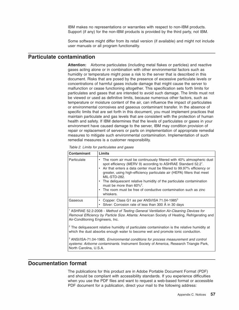
IBM makes no representations or warranties with respect to non-IBM products.Support (if any) for the non-IBM products is provided by the third party, not IBM.
Some software might differ from its retail version (if available) and might not includeuser manuals or all program functionality.
Particulate contaminationAttention: Airborne particulates (including metal flakes or particles) and reactivegases acting alone or in combination with other environmental factors such ashumidity or temperature might pose a risk to the server that is described in thisdocument. Risks that are posed by the presence of excessive particulate levels orconcentrations of harmful gases include damage that might cause the server tomalfunction or cease functioning altogether. This specification sets forth limits forparticulates and gases that are intended to avoid such damage. The limits must notbe viewed or used as definitive limits, because numerous other factors, such astemperature or moisture content of the air, can influence the impact of particulatesor environmental corrosives and gaseous contaminant transfer. In the absence ofspecific limits that are set forth in this document, you must implement practices thatmaintain particulate and gas levels that are consistent with the protection of humanhealth and safety. If IBM determines that the levels of particulates or gases in yourenvironment have caused damage to the server, IBM may condition provision ofrepair or replacement of servers or parts on implementation of appropriate remedialmeasures to mitigate such environmental contamination. Implementation of suchremedial measures is a customer responsibility.
Table 2. Limits for particulates and gases
Contaminant Limits
Particulate v The room air must be continuously filtered with 40% atmospheric dustspot efficiency (MERV 9) according to ASHRAE Standard 52.21.
v Air that enters a data center must be filtered to 99.97% efficiency orgreater, using high-efficiency particulate air (HEPA) filters that meetMIL-STD-282.
v The deliquescent relative humidity of the particulate contaminationmust be more than 60%2.
v The room must be free of conductive contamination such as zincwhiskers.
Gaseous v Copper: Class G1 as per ANSI/ISA 71.04-19853
v Silver: Corrosion rate of less than 300 Å in 30 days1 ASHRAE 52.2-2008 - Method of Testing General Ventilation Air-Cleaning Devices forRemoval Efficiency by Particle Size. Atlanta: American Society of Heating, Refrigerating andAir-Conditioning Engineers, Inc.
2 The deliquescent relative humidity of particulate contamination is the relative humidity atwhich the dust absorbs enough water to become wet and promote ionic conduction.
3 ANSI/ISA-71.04-1985. Environmental conditions for process measurement and controlsystems: Airborne contaminants. Instrument Society of America, Research Triangle Park,North Carolina, U.S.A.
Documentation formatThe publications for this product are in Adobe Portable Document Format (PDF)and should be compliant with accessibility standards. If you experience difficultieswhen you use the PDF files and want to request a web-based format or accessiblePDF document for a publication, direct your mail to the following address:
Appendix C. Notices 57

Information DevelopmentIBM Corporation205/A0153039 E. Cornwallis RoadP.O. Box 12195Research Triangle Park, North Carolina 27709-2195U.S.A.
In the request, be sure to include the publication part number and title.
When you send information to IBM, you grant IBM a nonexclusive right to use ordistribute the information in any way it believes appropriate without incurring anyobligation to you.
Telecommunication regulatory statementThis product may not be certified in your country for connection by any meanswhatsoever to interfaces of public telecommunications networks. Further certificationmay be required by law prior to making any such connection. Contact an IBMrepresentative or reseller for any questions.
Electronic emission noticesWhen you attach a monitor to the equipment, you must use the designated monitorcable and any interference suppression devices that are supplied with the monitor.
Federal Communications Commission (FCC) statementNote: This equipment has been tested and found to comply with the limits for aClass A digital device, pursuant to Part 15 of the FCC Rules. These limits aredesigned to provide reasonable protection against harmful interference when theequipment is operated in a commercial environment. This equipment generates,uses, and can radiate radio frequency energy and, if not installed and used inaccordance with the instruction manual, may cause harmful interference to radiocommunications. Operation of this equipment in a residential area is likely to causeharmful interference, in which case the user will be required to correct theinterference at his own expense.
Properly shielded and grounded cables and connectors must be used in order tomeet FCC emission limits. IBM is not responsible for any radio or televisioninterference caused by using other than recommended cables and connectors or byunauthorized changes or modifications to this equipment. Unauthorized changes ormodifications could void the user's authority to operate the equipment.
This device complies with Part 15 of the FCC Rules. Operation is subject to thefollowing two conditions: (1) this device may not cause harmful interference, and (2)this device must accept any interference received, including interference that maycause undesired operation.
Industry Canada Class A emission compliance statementThis Class A digital apparatus complies with Canadian ICES-003.
Avis de conformité à la réglementation d'Industrie CanadaCet appareil numérique de la classe A est conforme à la norme NMB-003 duCanada.
58 BladeCenter H Type 8852, 7989, and 1886: Installation and User’s Guide

Australia and New Zealand Class A statementAttention: This is a Class A product. In a domestic environment this product maycause radio interference in which case the user may be required to take adequatemeasures.
European Union EMC Directive conformance statementThis product is in conformity with the protection requirements of EU CouncilDirective 2004/108/EC on the approximation of the laws of the Member Statesrelating to electromagnetic compatibility. IBM cannot accept responsibility for anyfailure to satisfy the protection requirements resulting from a nonrecommendedmodification of the product, including the fitting of non-IBM option cards.
Attention: This is an EN 55022 Class A product. In a domestic environment thisproduct may cause radio interference in which case the user may be required totake adequate measures.
Responsible manufacturer:International Business Machines Corp.New Orchard RoadArmonk, New York 10504914-499-1900
European Community contact:IBM Deutschland GmbHTechnical Regulations, Department M372IBM-Allee 1, 71139 Ehningen, GermanyTelephone: +49 7032 15 2941Email: [email protected]
Germany Class A statementDeutschsprachiger EU Hinweis:
Hinweis für Geräte der Klasse A EU-Richtlinie zur ElektromagnetischenVerträglichkeit
Dieses Produkt entspricht den Schutzanforderungen der EU-Richtlinie 2004/108/EGzur Angleichung der Rechtsvorschriften über die elektromagnetische Verträglichkeitin den EU-Mitgliedsstaaten und hält die Grenzwerte der EN 55022 Klasse A ein.
Um dieses sicherzustellen, sind die Geräte wie in den Handbüchern beschrieben zuinstallieren und zu betreiben. Des Weiteren dürfen auch nur von der IBMempfohlene Kabel angeschlossen werden. IBM übernimmt keine Verantwortung fürdie Einhaltung der Schutzanforderungen, wenn das Produkt ohne Zustimmung derIBM verändert bzw. wenn Erweiterungskomponenten von Fremdherstellern ohneEmpfehlung der IBM gesteckt/eingebaut werden.
EN 55022 Klasse A Geräte müssen mit folgendem Warnhinweis versehen werden:“Warnung: Dieses ist eine Einrichtung der Klasse A. Diese Einrichtung kann imWohnbereich Funk-Störungen verursachen; in diesem Fall kann vom Betreiberverlangt werden, angemessene Maßnahmen zu ergreifen und dafür aufzukommen.”
Appendix C. Notices 59

Deutschland: Einhaltung des Gesetzes über dieelektromagnetische Verträglichkeit von GerätenDieses Produkt entspricht dem “Gesetz über die elektromagnetische Verträglichkeitvon Geräten (EMVG)”. Dies ist die Umsetzung der EU-Richtlinie 2004/108/EG inder Bundesrepublik Deutschland.
Zulassungsbescheinigung laut dem Deutschen Gesetz über dieelektromagnetische Verträglichkeit von Geräten (EMVG) (bzw. derEMC EG Richtlinie 2004/108/EG) für Geräte der Klasse ADieses Gerät ist berechtigt, in Übereinstimmung mit dem Deutschen EMVG dasEG-Konformitätszeichen - CE - zu führen.
Verantwortlich für die Einhaltung der EMV Vorschriften ist der Hersteller:International Business Machines Corp.New Orchard RoadArmonk, New York 10504914-499-1900
Der verantwortliche Ansprechpartner des Herstellers in der EU ist:IBM Deutschland GmbHTechnical Regulations, Abteilung M372IBM-Allee 1, 71139 Ehningen, GermanyTelephone: +49 7032 15 2941Email: [email protected]
Generelle Informationen:
Das Gerät erfüllt die Schutzanforderungen nach EN 55024 und EN 55022Klasse A.
VCCI Class A statement
This is a Class A product based on the standard of the Voluntary Control Council forInterference (VCCI). If this equipment is used in a domestic environment, radiointerference may occur, in which case the user may be required to take correctiveactions.
Japan Electronics and Information Technology Industries Association(JEITA) statement
Japanese Electronics and Information Technology Industries Association (JEITA)Confirmed Harmonics Guideline (products less than or equal to 20 A per phase)
60 BladeCenter H Type 8852, 7989, and 1886: Installation and User’s Guide
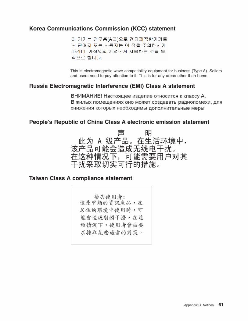
Korea Communications Commission (KCC) statement
This is electromagnetic wave compatibility equipment for business (Type A). Sellersand users need to pay attention to it. This is for any areas other than home.
Russia Electromagnetic Interference (EMI) Class A statement
People's Republic of China Class A electronic emission statement
Taiwan Class A compliance statement
Appendix C. Notices 61

62 BladeCenter H Type 8852, 7989, and 1886: Installation and User’s Guide
Index
Aaccessible documentation 57activity LED
optical drive 14airflow 3assistance, getting 51
Bbefore you begin 17bezels
installing 31removing 23
blade serverdescription 4installing 31removing 19, 21
BladeCenterconfiguring 35
BladeCenter machine typelocating 2
BladeCenter model numberlocating 2
BladeCenter modulesdescription 3
BladeCenter powerdisconnecting 11supplying 11
BladeCenter serial numberlocating 2
BladeCenter unitinstallation requirements 17management module 17power modules 17
blower module 5installing 24problems 43removing 22
Cchecklist, installation 17Class A electronic emission notice 58configuration sheet
management module 47configuring
BladeCenter unit 35I/O module 35
configuring the management module 35connector
Universal Serial Bus 14connectors
front 12contamination, particulate and gaseous 57controls 12
front 12cooling 3
Ddescription
blade server 4BladeCenter modules 3management module 4
diagnostic data 52diagnostic LEDs 44diagnostic tools 41display problems 42documentation CD
starting 6using 6
documentation format 57DVD drive
problems 44Dynamic System Analysis 52
Eeject button
CD 14electrical input 3electronic emission Class A notice 58environment 3Ethernet switch module
preinstallation requirements 17
FFCC Class A notice 58features and specifications 3front system panel
LEDs 13
Ggaseous contamination 57getting help 51
Hhandling
static-sensitive devices 18hardware problems 41hardware service and support 53heat output 3help, getting 51
II/O module
configuring 35installing 27removing 22
IBM Director 37IBM Support Line 52
© Copyright IBM Corp. 2012 63
information LEDsystem LED panel 13
installation completion 32installation requirements 17installing
bezels 31blade server 31blower module 24I/O module 27in a rack 17management module 26optical drive 30options 17, 18power module 28
LLEDs
errorsystem 14
front 12front system panel 13information
system LED panel 13location
blade server 13BladeCenter 13
optical drive activity 14over-temp 13power module 12power-on
system LED panel 13rear view 15system error
blade server 14system LED panel 14
light path diagnostics feature 41, 44light path diagnostics table 45locating
BladeCenter machine type 2BladeCenter model number 2BladeCenter serial number 2
Mmanagement module 4
alerts 49configuration sheet 47configuring 35description 4external network interface 48general settings 47installing 26internal network interface 48login profiles 47network protocols 50problems 43removing 21security 50
media trayproblems 44
moduleblower 5management 4power 5
monitor problems 42
Nnetworking guidelines 36notes, important 56notices 55
electronic emission 58FCC, Class A 58
Ooptical drive
installing 30problems 44
Optical driveactivity LED 14eject button 14
optical fillerremoving 24
optionsinstalling 18
over-temp LED 13
Pparticulate contamination 57power
problems 42power module 5
installing 28LEDs 12
power-on LEDsystem LED panel 13
prerequisites 17problem
hardware 41solving 41
problemsblower module 43management module 43media tray 44monitor 42optical drive 44power 42video 42
product data 1public services network, use in 58public telecommunications network, connection to 58
Rrack, installing BladeCenter in 17removing
bezels 23blade server 19, 21
64 BladeCenter H Type 8852, 7989, and 1886: Installation and User’s Guide
removing (continued)blower module 22I/O module 22management module 21optical filler 24
Ssize 3software service and support 52status LEDs 12, 15system error LED
system LED panel 14system reliability 18system specifications 3systems management 37
Ttelephone numbers 53trademarks 55troubleshooting 41
charts 41
UUnited States electronic emission Class A notice 58United States FCC Class A notice 58
Vvideo output, unexpected or blank 39video problems 42
Wwebsite
personalized support 52publication ordering 52support line, telephone numbers 53
weight 3
Index 65

66 BladeCenter H Type 8852, 7989, and 1886: Installation and User’s Guide


����
Part Number: 46W8120
Printed in USA
(1P) P/N: 46W8120


![8852. Nomination of Class B Director...FEDERAL RESERVE BANK OF NEW YORK [Circular No. 8852 June 16, 1980] Nomination of Class B Director For Unexpired Portion of Term Ending December](https://static.fdocuments.net/doc/165x107/60a91de43b70aa42d91ae561/8852-nomination-of-class-b-director-federal-reserve-bank-of-new-york-circular.jpg)