
Installation and User Manual IEC en 201202
6
Yingli So lar PV Modules, Installation an d User Manual / page 1 This manual applies to photovoltaic modules (“PV modules”, also commonly known as solar panels) manufac-tured by Yingli Green Energy Holding Co. Ltd. (“Yingli Solar”), and is explicitly written for qualied professionals (“Installer” or “Installers”), including without limitation licensed electricians and RAL Certied PV Installers. INTRODUCTION Thank you for choosing Yingli Solar as your PV module provider. We appreciate your business! This manual contains important information pertaining to the electrical and mechanical installation and maintenance of PV modules, and contains safety information that you must read carefully and be familiar with before handling, installing, and/or maintaining Yingli Solar PV modules. Yingli Solar does not assume responsibility and expressly disclaims liability for losses, damages, or expenses arising out of, or in any way connected with this Installation and User Manual. Yingli Solar assumes no responsibility for any infringement of patents or other rights of third parties, which may result from using Yingli Solar PV modules. No license is granted expressly or by implication or under any patent or patent rights. The information in this manual is believed to be reliable, but does not constitute an expressed or implied warranty. Yingli Solar reserves the right to make changes to its PV modules and other products, their specications, or this manual without prior notice. Yingli Solar and its subsidiaries are not liable for any damages caused by inappropriate installation, use, or maintenance of Yingli Solar PV modules, including without limitation damages, losses, and expenses caused by non-observance of the instructions of this manual or caused by or in connection with products of other manufacturers. Yingli Solar PV modules are designed to meet the requirements for the standards IEC 61215 and IEC 61730, application class A. Modules rated for use in this application class may be used in systems operating at greater than 50 V DC or 240 W, where general contact access is anticipated. Modules qualied for safety through IEC 61730-1 and IEC 61730-2 and within this application class are considered to meet the requirements for safety class II. In the course of the PV module certication process, the compliance of this manual with the certication requirements has been veried by an independent certication laboratory. This Installation and User Manual is available in different languages. In cases of discrepancy between versions, the English language version shall control. Failure to comply with the requirements listed in this manual will invalidate the Limited Warranty for PV Modules as provided by Yingli Solar at the time of sale to t he direct customer. Additional recommendati ons are provided to enhance safety practices and performance results. Please provide a copy of this manual to the PV system owner for their reference, and inform them of all relevant aspects of safety, operation, and maintenance. SAFETY General Y ou must understand and follow all applicable local, state, and federal regulations and standards for building construction, electrical design, re, and safety, and must check with local authorities to deter mine applicable permitting requirements before attempting to install or maintain PV modules. Rooftop PV systems should only be installed on dwellings that have been formally analyzed for structural integrity, and conrmed to be capable of handling the additional weighted load of PV system components, including PV modules, by a certied building specialist or engineer. For your safety, do not attempt to work on a rooftop until safety precautions have been identied and taken, including without limitation fall protection measures, ladders or stairways, and personal protective equipment (PPE). For your safety, do not install or handle PV modules under adverse conditions, including without limitation strong or gusty winds, and wet or frosted roof surfaces. The at-plate PV module construction consists of a laminated assembly of solar cells encapsulated within an insulating material with a rigid glass surface and an insulated substrate. The laminated assembly is supported by an aluminum frame that is also used for mounting the module. See Figure 1 for an illustration of the PV module components. Figure 1: Module components and cross-section of the laminated assembly Electrical PV modules can produce current and voltage when exposed to light of any intensity. Electrical current increases with higher light intensity. DC voltage of 30 Volts or higher is potentially lethal. Contacting the live circuitry of a PV system operating under light can result in lethal electric shock. De-energize PV modules by removing them entirely from light or by covering their front surface with an opaque material. Regard the safety regulations for live electrical equipment when working with modules that are exposed to any light. Use insulated tools and do not wear metallic jewelry while working with PV m odules. Junction Box Cable Connector Cell Frame 1 1. Aluminum Frame 2. Glass 3. Encapsulating EVA 4. PV Cell 5. Backsheet 2 3 5 4 YING L I S OL A R . C O M YIN GLI SOL AR PV MOD ULES Installation and User Manual Revision Date December 24, 2011 | Applicable for IEC certied products
-
Upload
nenad-nestorovic -
Category
Documents
-
view
228 -
download
0
Transcript of Installation and User Manual IEC en 201202

8/14/2019 Installation and User Manual IEC en 201202
http://slidepdf.com/reader/full/installation-and-user-manual-iec-en-201202 1/5
Yingli Solar PV Modules, Installation and User Manual / page 1
This manual applies to photovoltaic modules (“PVmodules”, also commonly known as solar panels)manufac-tured by Yingli Green Energy Holding Co. Ltd.(“Yingli Solar”), and is explicitly written for qualiedprofessionals (“Installer” or “Installers”), includingwithout limitation licensed electricians and RAL CertiedPV Installers.
INTRO DUCT IO N
Thank you for choosing Yingli Solar as your PV module provider. Weappreciate your business! This manual contains important information
pertaining to the electrical and mechanical installation and maintenanceof PV modules, and contains safety information that you must read carefullyand be familiar with before handling, installing, and/or maintaining YingliSolar PV modules.
Yingli Solar does not assume responsibility and expressly disclaimsliability for losses, damages, or expenses arising out of, or in any wayconnected with this Installation and User Manual. Yingli Solar assumesno responsibility for any infringement of patents or other rights of thirdparties, which may result from using Yingli Solar PV modules. No licenseis granted expressly or by implication or under any patent or patentrights. The information in this manual is believed to be reliable, but doesnot constitute an expressed or implied warranty. Yingli Solar reservesthe right to make changes to its PV modules and other products, theirspecications, or this manual without prior notice.
Yingli Solar and its subsidiaries are not liable for any damages caused byinappropriate installation, use, or maintenance of Yingli Solar PV modules,including without limitation damages, losses, and expenses caused bynon-observance of the instructions of this manual or caused by or inconnection with products of other manufacturers.
Yingli Solar PV modules are designed to meet the requirements for thestandards IEC 61215 and IEC 61730, application class A. Modules rated foruse in this application class may be used in systems operating at greaterthan 50 V DC or 240 W, where general contact access is anticipated.Modules qualied for safety through IEC 61730-1 and IEC 61730-2 andwithin this application class are considered to meet the requirements forsafety class II. In the course of the PV module certication process, thecompliance of this manual with the certication requirements has beenveried by an independent certication laboratory.
This Installation and User Manual is available in different languages. Incases of discrepancy between versions, the English language version shallcontrol.
Failure to comply with the requirements listed in this manual will invalidatethe Limited Warranty for PV Modules as provided by Yingli Solar at the timeof sale to the direct customer. Additional recommendations are providedto enhance safety practices and performance results. Please provide acopy of this manual to the PV system owner for their reference, and informthem of all relevant aspects of safety, operation, and maintenance.
SAFE TY
General You must understand and follow all applicable local, state, and federalregulations and standards for building construction, electrical design, re,and safety, and must check with local authorities to determine applicablepermitting requirements before attempting to install or maintain PVmodules.
Rooftop PV systems should only be installed on dwellings that have beenformally analyzed for structural integrity, and conrmed to be capableof handling the additional weighted load of PV system components,including PV modules, by a certied building specialist or engineer.
For your safety, do not attempt to work on a rooftopuntil safety precautions have been identied and taken,including without limitation fall protection measures,ladders or stairways, and personal protective equipment(PPE).
For your safety, do not install or handle PV modules under adverseconditions, including without limitation strong or gusty winds, and wet orfrosted roof surfaces.
The at-plate PV module construction consists of a laminated assemblyof solar cells encapsulated within an insulating material with a rigid glasssurface and an insulated substrate. The laminated assembly is supportedby an aluminum frame that is also used for mounting the module. SeeFigure 1 for an illustration of the PV module components.
Figure 1: Module components and cross-section of the laminated assembly
ElectricalPV modules can produce current and voltage whenexposed to light of any intensity. Electrical currentincreases with higher light intensity. DC voltage of 30 Voltsor higher is potentially lethal. Contacting the live circuitryof a PV system operating under light can result in lethalelectric shock.
De-energize PV modules by removing them entirely from light or bycovering their front surface with an opaque material. Regard the safetyregulations for live electrical equipment when working with modules thatare exposed to any light. Use insulated tools and do not wear metallic
jewelry while working with PV modules.
Junction Box
Cable
Connector
Cell
Frame
1
1. Aluminum Frame2. Glass3. Encapsulating EVA4. PV Cell5. Backsheet
2
3
5
4
Y INGLISOLAR.COM
YINGLI SOLAR PV MODULES
Installation and User ManualRevision Date December 24, 2011 | Applicable for IEC certied products

8/14/2019 Installation and User Manual IEC en 201202
http://slidepdf.com/reader/full/installation-and-user-manual-iec-en-201202 2/5
Yingli Solar PV Modules, Installation and User Manual / page 2
In order to avoid arcing and electrical shock, do not disconnect electricalconnections under load. Faulty connections can also result in arcing andelectrical shock. Keep connectors dry and clean, and ensure that theyare in proper working condition. Never insert metallic objects into theconnectors, or modify them in any way in order to secure an electricalconnection.
Do not touch or handle PV modules with broken glass, separated framesor a damaged backsheet unless the PV modules are rst disconnectedand you are wearing proper PPE. Avoid handling PV modules when theyare wet unless cleaning the PV modules as directed in this manual. Never
touch electrical connections that are wet without protecting yourself withinsulated gloves.
Transport and Handling Yingli Solar PV modules must be transported in the supplied packagingonly and kept in the packaging until they are ready to be installed. Protectpallets against movement and exposure to damage during transportation.Secure pallets from falling over. Do not exceed the maximum height ofpallets to be stacked, as indicated on the pallet packaging. Store pallets ina cool and dry location until the PV modules are ready to be unpackaged.
Figure 2: Pallet of PV modules
Yingli Solar PV modules are heavy, and should be handled with care. PVmodules shall be handled at the frame; never use the junction box orcables as a grip. Do not exert mechanical stress on the cables. Never stepon PV modules or drop or place heavy objects on them. Be careful whenplacing PV modules on hard surfaces, and secure them from falling. Brokenglass can result in personal injury. PV modules with broken glass cannot berepaired and must not be used. Broken or damaged PV modules must behandled carefully and disposed of properly.
For unpacking PV modules from the Yingli Solar supplied packaging, rstremove the pallet lid (after removing securing straps, if provided). RemovePV modules one at a time by sliding them up the channel in the package(see Figure 3). You may need to secure the remaining PV modules in thepallet packaging to prevent them from falling over.
Figure 3: Removing PV modules from a pallet
Check PV modules for damage due to transportation before they areinstalled; do not install damaged modules. Contact the company youpurchased the Yingli Solar PV modules from in order to obtain informationon making claims for defective PV modules.
PV module surfaces are susceptible to damage that could affect theperformance or safety of the PV module; do not damage or scratch the PVmodule surfaces, and do not apply paint or adhesive to any of the surfaces,including the frame. For your safety, do not disassemble or modify YingliSolar PV modules in any way. Doing so may degrade performance orcause irreparable damage and will void any applicable warranties.
If it is necessary to store PV modules prior to installation, the PV modules
should remain inside the packaging and protected from exposure thatcould compromise the durability of the packaging.
Fire Yingli Solar PV Modules have a Class C re resistance rating in accordancewith the IEC 61730-2 certication. When PV modules are mounted onrooftops, the roof must have a re resistant covering suitable for thisapplication. PV modules are electrical generating devices that may affectthe re safety of a building.
The use of improper installation methods and/or defective parts mayresult in the unexpected occurrence of an electrical arc during operation.In order to mitigate the risk of re in this event, PV modules should notbe installed near ammable liquids, gases, or locations with hazardous
materials.In the event of a re, PV modules may continue to produce a dangerousvoltage, even if they have been disconnected from the inverter, have beenpartly or entirely destroyed, or the system wiring has been compromisedor destroyed. In the event of re, inform the re crew about the particularhazards from the PV system, and stay away from all elements of the PVsystem during and after a re until the necessary steps have been taken tomake the PV system safe.
APPL ICAT ION INFORMATION
Application Restrictions Yingli Solar PV modules must be mounted on appropriate mountingstructures positioned on suitable buildings, the ground, or other structures
suitable for PV modules (e.g. carports, building facades or PV trackers). PVmodules must not be mounted on moving vehicles of any kind. YingliSolar PV modules must not be installed in locations where they could besubmerged in water.
Yingli Solar PV modules must not be sited in locations where aggressivesubstances such as salt or salt-water, or any other type of corrosive agent,could affect the safety and/or performance of the PV modules. Althoughsome types of Yingli Solar PV modules have passed the IEC 61701 salt-mist corrosion test with a salt concentration of 5% by weight, galvaniccorrosion can occur between the aluminum frame of the PV moduleand mounting or grounding hardware if such hardware is comprised ofdissimilar metals. Yingli Solar recommends that only stainless steel andaluminum metal directly contact PV modules in seaside installations tolimit corrosion.
Articially concentrated light must not be directed on Yingli Solar PVmodules.
Design Recommendations Yingli Solar recommends that PV modules be mounted at a minimum tiltangle of 10 degrees to allow for proper self-cleaning from normal rainshowers.
Partial or complete shading of a PV module or modules can signicantlyreduce system performance. Yingli Solar recommends minimizing theamount of shade throughout the year to increase the amount of energyproduced by the PV modules.
Lightning protection is recommended for PV systems that are to beinstalled in locations with high probability of lightning strikes.
High system voltages could be induced in the event of an indirectlightning strike, which could cause damage to PV system components.The open area of wire loops should be minimized, as shown in Figure 4,in order to reduce the r isk of lightning induced voltage surges.
Figure 4: Wire loop design recommendation

8/14/2019 Installation and User Manual IEC en 201202
http://slidepdf.com/reader/full/installation-and-user-manual-iec-en-201202 3/5
Yingli Solar PV Modules, Installation and User Manual / page 3
ELECTRICAL INSTALLAT ION
Electrical ConfgurationUnder normal conditions, a photovoltaic module is likely to experienceconditions that produce more current and/or voltage than reportedat Standard Test Conditions (STC: 1000 W/m2, AM 1.5, and 25℃ celltemperature). The short-circuit current (ISC) should be multiplied by afactor of 1.25 and the open-circuit voltage (V
OC) should be multiplied
by a factor of up to 1.25 based on the lowest ambient temperaturerecorded for the installation location when determining componentvoltage ratings, conductor current ratings, fuse sizes, and size of controlsconnected to the PV output.
Voltages are additive when PV modules are connected directly in series,and module currents are additive when PV modules are connecteddirectly in parallel, as illustrated in Figure 5. PV modules with differentelectrical characteristics must not be connected directly in series. The useof suitable third-party electronic devices connected to PV modules mayenable different electrical connections and must be installed according tothe manufacturer’s specied instructions.
Figure 5: Electrical diagrams of series and parallel wiring
The maximum number of PV modules that can be connected in a seriesstring must be calculated in accordance with applicable regulations in sucha way that the specied maximum system voltage of the PV module andall other electrical DC components will not be exceeded in open-circuitoperation at the lowest temperature expected at the PV system location.
An appropriately rated overcurrent protection device must be used whenthe reverse current could exceed the value of the maximum fuse rating ofthe module. An overcurrent protection device is required for each seriesstring if more than two series strings are connected in parallel.
Cables and Wiring Yingli Solar PV modules are provided with two (2) stranded, sunlightresistant output cables that are terminated with PV connectors readyfor most installations. The positive (+) terminal has a female connector
while the negative (-) terminal has a male connector. The module wiring isintended for series connections [i.e. female (+) to male (-) interconnections],but can also be used to connect suitable third-party electrical devices thatmay have alternative wiring congurations so long as the manufacturer’sinstructions are followed.
Use eld wiring with suitable cross-sectional areas that are approved foruse at the maximum short-circuit current of the PV module. Yingli Solarrecommends installers use only sunlight resistant cables qualied fordirect current (DC) wiring in PV systems. The minimum wire size shouldbe 4mm2.
Testing Standard Wire Size Temperature Rating
Required Minimum Field Wiring TÜV 2 PfG 1169 4mm2 -40ºC to +90ºC
Table 1: Required minimum feld wiring specifcations
Cables should be xed to the mounting structure in such a way thatmechanical damage of the cable and/or the module is avoided. Do notapply stress to the cables. For xing, use appropriate means, such as
sunlight resistant cable ties and/or wire management clips specicallydesigned to attach to the PV module frame. While the cables are sunlightresistant and waterproof, where possible, avoid direct sunlight exposureand water immersion of the cables.
ConnectorsKeep connectors dry and clean, and ensure thatconnector caps are hand tight before connectingthe modules. Do not attempt making an electricalconnection with wet, soiled, or otherwise faultyconnectors. Avoid sunlight exposure and waterimmersion of the connectors. Avoid connectorsresting on the ground or roof surface.
Faulty connections can result in arcs and electrical shock. Check that allelectrical connections are securely fastened. Make sure that all lockingconnectors are fully engaged and locked.
Figure 6: Series interconnection of a male (-) and female (+) connector
Bypass DiodesThe junction boxes used with Yingli Solar PV modules contain bypassdiodes wired in parallel with the PV cell strings. In the case of partialshading, the diodes bypass the current generated by the non-shadedcells, thereby limiting module heating and performance losses. Bypassdiodes are not overcurrent protection devices.
Bypass diodes divert current from the cell strings in the event of partialshading. See Figure 7 for a diagram showing how the cell strings areelectrically connected with the diodes.
Figure 7: Electrical circuitry of cells and bypass diodes
In the event of a known or suspected diode failure, installers ormaintenance providers should contact the company the PV modules werepurchased from. Never attempt to open the junction box of a Yingli SolarPV module yourself.
Equipment GroundingThe frame of the PV module, as well as any exposed non-current-carryingmetal parts of xed equipment that are able to become energized by thePV system, must be connected to the equipment grounding conductor(EGC) in order to prevent electrical shock. Even when applicableregulations, code requirements, and standards do not require safety-related grounding, Yingli Solar recommends grounding all PV moduleframes in order to ensure the voltage between electrically conductiveequipment and earth ground is zero in all circumstances
Proper equipment grounding is achieved by bonding all exposed non-current-carrying metal equipment continuously to one another using an
appropriately sized EGC or racking system that can be used for integratedgrounding (see Option B in Grounding Methods below).
Yingli Solar PV modules employ a coated aluminum frame for corrosionresistance. In order to properly ground the module frame, the coatingmust be penetrated.
Series wiring (voltage additive)
Parallel wiring (current additive)
Fully engage and lock
Cap
+–
8/14/2019 Installation and User Manual IEC en 201202
http://slidepdf.com/reader/full/installation-and-user-manual-iec-en-201202 4/5
Yingli Solar PV Modules, Installation and User Manual / page 4
The potential for corrosion due to the electrochemical action betweendissimilar metals in contact is minimized if the electrochemical voltagepotential between the dissimilar metals is low. The grounding methodmust not result in the direct contact of dissimilar metals with thealuminum frame of the PV module that will result in galvanic corrosion.An addendum to UL Standard 1703 “Flat Plate Photovoltaic Modules andPanels” recommends metal combinations not exceed an electrochemicalpotential difference of 0.5 Volts.
The frame rails have pre-drilled holes marked with a grounding sign,as illustrated in Figure 8. These holes should be used for groundingpurposes and must not be used for mounting the PV modules. Do not drilladditional holes into the frame rails.
Figure 8: Grounding hole detail
The following grounding methods are available:
Option A: Screw Assembly (see Figure 9)
1. A grounding screw assembly must be attached at a designatedgrounding hole location using only stainless steel hardware. Insert anM5 stainless steel screw rst through the stainless steel cup washer, andthen through the grounding hole.
2. Loosely engage a stainless steel backing nut and toothed lock washerto the screw.
Figure 9: Grounding screw assembly detail
3. Bend the EGC into an omega (Ω) shape to tightly t between the partially
installed screw head and cup washer. The EGC shall be exclusively incontact with stainless steel.
4. Tighten the screw to 2.3 N∙m torque. The toothed lock washer shouldbe visibly engaged to the frame.
5. Route the appropriately sized EGC in such a way as to avoid contactwith the aluminum module frame.
Option B: Racking Manufacturer IntegratedGrounding Methods
Yingli Solar PV modules can be grounded by bonding PV modules toa grounded racking system. Integrated grounding methods must becertied for grounding PV modules and must be installed in accordance
with the specied instructions of their respective manufacturers.
Option C: Additional Third-party Grounding Devices
Yingli Solar PV modules can be grounded using third party groundingdevices so long as they are certied for grounding PV modules and thedevices are installed according to the manufacturer’s specied instructions.
MECHANICAL INSTALLAT ION
General Yingli Solar PV Modules have been certied for a maximum static load onthe back of the module of up to 2400 Pa (i.e. wind load) and a maximumstatic load on the front of the module of up to either 2400 Pa or 5400 Pa(i.e. wind and snow load), depending on the module type (please refer tothe data sheet for this information).
Mounting structures and other mechanical parts must be designed andapproved to withstand the design wind and snow loads applicable for aparticular site. Yingli Solar PV modules must not be subjected to forcesfrom the substructure, including forces caused by thermal expansion.
The mounting method must not result in the direct contact of dissimilarmetals with the aluminum frame of the PV module that will result in galvaniccorrosion. An addendum to UL Standard 1703 “Flat Plate PhotovoltaicModules and Panels” recommends metal combinations not exceed an
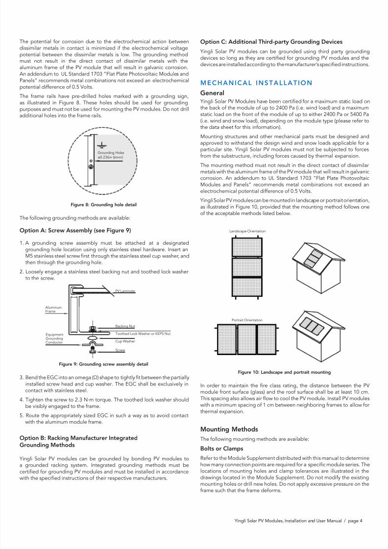
electrochemical potential difference of 0.5 Volts. Yingli Solar PV modules can be mounted in landscape or portrait orientation,as illustrated in Figure 10, provided that the mounting method follows oneof the acceptable methods listed below.
Figure 10: Landscape and portrait mounting
In order to maintain the re class rating, the distance between the PVmodule front surface (glass) and the roof surface shall be at least 10 cm.This spacing also allows air ow to cool the PV module. Install PV moduleswith a minimum spacing of 1 cm between neighboring frames to allow forthermal expansion.
Mounting Methods
The following mounting methods are available:
Bolts or Clamps
Refer to the Module Supplement distributed with this manual to determinehow many connection points are required for a specic module series. Thelocations of mounting holes and clamp tolerances are illustrated in thedrawings located in the Module Supplement. Do not modify the existingmounting holes or drill new holes. Do not apply excessive pressure on theframe such that the frame deforms.
Grounding Holes
ø0.236in (6mm)
PV Laminate
Backing Nut
Toothed Lock Washer or KEPS Nut
Cup Washer
AluminumFrame
Screw
EquipmentGroundingConductor
Landscape Orientation
Portrait Orientation
8/14/2019 Installation and User Manual IEC en 201202
http://slidepdf.com/reader/full/installation-and-user-manual-iec-en-201202 5/5
Yingli Solar PV Modules, Installation and User Manual / page 5
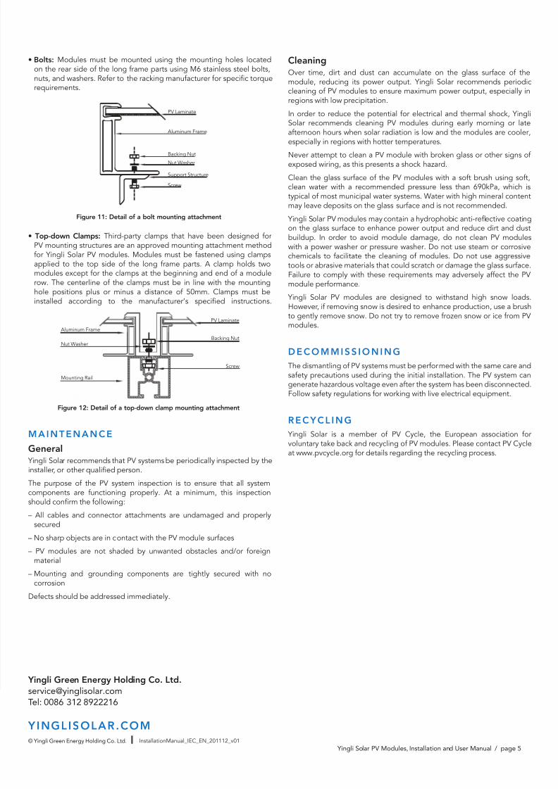
• Bolts: Modules must be mounted using the mounting holes locatedon the rear side of the long frame parts using M6 stainless steel bolts,nuts, and washers. Refer to the racking manufacturer for specic torquerequirements.
Figure 11: Detail of a bolt mounting attachment
• Top-down Clamps: Third-party clamps that have been designed forPV mounting structures are an approved mounting attachment methodfor Yingli Solar PV modules. Modules must be fastened using clampsapplied to the top side of the long frame parts. A clamp holds two
modules except for the clamps at the beginning and end of a modulerow. The centerline of the clamps must be in line with the mountinghole positions plus or minus a distance of 50mm. Clamps must beinstalled according to the manufacturer’s specied instructions.
Figure 12: Detail of a top-down clamp mounting attachment
M AINTE NANCE
General Yingli Solar recommends that PV systems be periodically inspected by theinstaller, or other qualied person.
The purpose of the PV system inspection is to ensure that all systemcomponents are functioning properly. At a minimum, this inspectionshould conrm the following:
– All cables and connector attachments are undamaged and properlysecured
– No sharp objects are in contact with the PV module surfaces
– PV modules are not shaded by unwanted obstacles and/or foreignmaterial
– Mounting and grounding components are tightly secured with nocorrosion
Defects should be addressed immediately.
CleaningOver time, dirt and dust can accumulate on the glass surface of themodule, reducing its power output. Yingli Solar recommends periodiccleaning of PV modules to ensure maximum power output, especially inregions with low precipitation.
In order to reduce the potential for electrical and thermal shock, YingliSolar recommends cleaning PV modules during early morning or lateafternoon hours when solar radiation is low and the modules are cooler,especially in regions with hotter temperatures.
Never attempt to clean a PV module with broken glass or other signs ofexposed wiring, as this presents a shock hazard.
Clean the glass surface of the PV modules with a soft brush using soft,clean water with a recommended pressure less than 690kPa, which istypical of most municipal water systems. Water with high mineral contentmay leave deposits on the glass surface and is not recommended.
Yingli Solar PV modules may contain a hydrophobic anti-reective coatingon the glass surface to enhance power output and reduce dirt and dustbuildup. In order to avoid module damage, do not clean PV moduleswith a power washer or pressure washer. Do not use steam or corrosivechemicals to facilitate the cleaning of modules. Do not use aggressivetools or abrasive materials that could scratch or damage the glass surface.
Failure to comply with these requirements may adversely affect the PVmodule performance.
Yingli Solar PV modules are designed to withstand high snow loads.However, if removing snow is desired to enhance production, use a brushto gently remove snow. Do not try to remove frozen snow or ice from PVmodules.
DE CO M M ISS IO NING
The dismantling of PV systems must be performed with the same care andsafety precautions used during the initial installation. The PV system cangenerate hazardous voltage even after the system has been disconnected.Follow safety regulations for working with live electrical equipment.
RE CYCL ING
Yingli Solar is a member of PV Cycle, the European association forvoluntary take back and recycling of PV modules. Please contact PV Cycleat www.pvcycle.org for details regarding the recycling process.
PV Laminate
Backing Nut
Aluminum Frame
Nut Washer
Support Structure
Screw
Screw
Backing NutNut Washer
PV Laminate
Mounting Rail
Aluminum Frame
Yingli Green Energy Holding Co. Ltd.
[email protected]: 0086 312 8922216
Y INGLISOLAR.COM© Yingli Green Energy Holding Co. Ltd. InstallationManual_IEC_EN_201112_v01


