
INSTALLATION AND OPERATION MANUAL · 2019-12-23 · installation and operation manual eaton 93e ups...
133
INSTALLATION AND OPERATION MANUAL Eaton 93E UPS 15-80 kVA (380/400/415 V) 614-01975-00
Transcript of INSTALLATION AND OPERATION MANUAL · 2019-12-23 · installation and operation manual eaton 93e ups...
INSTALLATION AND OPERATION MANUAL
Eaton 93E UPS 15-80 kVA (380/400/415 V)
614-01975-00
Eaton 93E UPS 15-80 kVA (380/400/415 V) Installation and Operation Manual
© Eaton Corporation plc 2015. All rights reserved. Revision: 001 Document ID: 614-01975-00 3 (133)
Copyright © 2015 Eaton Corporation. All rights reserved.
This manual contains important instructions that you should follow during installation and maintenance of the UPS and batteries. Please read all instructions before operating the equipment and save this manual for future reference.
The contents of this manual are the copyright of the publisher and may not be reproduced (even extracts) without the written approval of Eaton Corporation. Every care has been taken to ensure the accuracy of the information contained in this manual, but no liability can be accepted for any errors or omission. The right to make design modifications is reserved.
Unauthorized copying and lending are prohibited.
Eaton Power Quality Oy
Address: Koskelontie 13
FI-02920 Espoo
Finland
Internet: www.eaton.eu
Approvals and version history
REVISION DATE DESCRIPTION OF CHANGE APPROVED BY
001 28.09.2015 First issue Otto Asunmaa
Original instructions _X_ / Translation of the original instructions ___
Eaton 93E UPS 15-80 kVA (380/400/415 V) Installation and Operation Manual
© Eaton Corporation plc 2015. All rights reserved. Revision: 001 Document ID: 614-01975-00 4 (133)
Contents
Contents ..................................................................................................................4 1 How to read this manual .............................................................................8
1.1 Safety-related signs ....................................................................... 8 1.2 Safety symbols .............................................................................. 8
1.2.1 Hazard symbols ................................................................ 8 1.2.3 Prohibited action symbols ................................................. 9 1.2.4 Mandatory action symbols ................................................ 9
1.3 Conventions used in this document .............................................. 9 2 Safety instructions ........................................................................................11
2.1 Audience ....................................................................................... 14 2.2 CE marking .................................................................................... 14 2.3 User precautions ........................................................................... 14 2.4 Environment .................................................................................. 15 2.5 Using this manual .......................................................................... 16 2.6 Symbols on the UPS and accessories ........................................... 17 2.7 For more information ..................................................................... 17
3 Introduction to Eaton UPS ..........................................................................19 3.1 UPS standard features .................................................................. 20
3.1.1 Installation features........................................................... 20 3.1.2 Control panel .................................................................... 20 3.1.3 Communication interface .................................................. 21 3.1.4 High-efficiency mode ........................................................ 21 3.1.5 Advanced Battery Management ........................................ 21 3.1.6 Maintenance bypass ......................................................... 21
3.2 Options and accessories ............................................................... 21 3.2.1 External battery cabinet .................................................... 22 3.2.2 Parallel system .................................................................. 22 3.2.3 Monitoring and communication ......................................... 22 3.2.4 Single feed ........................................................................ 23
3.3 Battery system .............................................................................. 23 3.4 Basic system configurations .......................................................... 23
4 UPS installation plan and unpacking .........................................................24 4.1 Creating an installation plan ........................................................... 25 4.2 Installation checklist ...................................................................... 25
4.2.1 Parallel system installation checklist ................................. 26 4.3 Site preparations ........................................................................... 27
4.3.1 Environmental and installation considerations ................... 27 4.3.2 UPS system power cabling preparation ............................ 38
Eaton 93E UPS 15-80 kVA (380/400/415 V) Installation and Operation Manual
© Eaton Corporation plc 2015. All rights reserved. Revision: 001 Document ID: 614-01975-00 5 (133)
4.3.3 UPS system interface wiring preparation .......................... 45 4.4 Inspecting and unpacking the UPS cabinets .................................. 46
5 UPS system installation ...............................................................................49 5.1 Preliminary installation information ................................................ 49 5.2 Unloading the UPS cabinet from the pallet .................................... 49 5.3 External power cabling installation................................................. 52 5.4 Battery system installation ............................................................ 56
5.4.1 External battery cabinet installation ................................... 57 5.4.2 1 + 1 common battery system .......................................... 59
5.5 Installing interface connections ..................................................... 60 5.5.1 Installing signal input connections ..................................... 61
5.6 Installing parallel wiring and connections ....................................... 64 5.6.1 Installing MiniSlot interface connections ........................... 68
5.7 Installing a remote EPO switch ..................................................... 68 5.8 Initial startup ................................................................................. 72 5.9 Completing the installation checklist ............................................. 72
6 Understanding UPS operation ...................................................................73 6.1 UPS system overview ................................................................... 73 6.2 Single UPS .................................................................................... 73
6.2.1 Modes .............................................................................. 74 6.2.2 Standard normal mode ...................................................... 74 6.2.3 High-efficiency mode ........................................................ 76 6.2.4 Bypass mode .................................................................... 76 6.2.5 Battery mode .................................................................... 78
6.3 Single UPS unit system oneline configurations .............................. 80 7 UPS operating instructions ..........................................................................83
7.1 UPS controls and indicators ........................................................... 83 7.1.1 Control panel .................................................................... 85
7.2 Using the control panel ................................................................. 85 7.2.1 Status indicators ............................................................... 86 7.2.2 System events .................................................................. 87 7.2.3 Using the LCD and push buttons ...................................... 88 7.2.4 Using the menu ................................................................ 90 7.2.5 Mimic screen .................................................................... 91 7.2.6 Display menu operation .................................................... 91 7.2.7 System controls ................................................................ 97
7.3 Single UPS operation ..................................................................... 99 7.3.1 Starting the UPS in the bypass mode ................................ 99 7.3.2 Starting the UPS in the standard normal mode (default
mode) ............................................................................... 100 7.3.3 Transfer from the bypass mode to the normal mode ........ 101
Eaton 93E UPS 15-80 kVA (380/400/415 V) Installation and Operation Manual
© Eaton Corporation plc 2015. All rights reserved. Revision: 001 Document ID: 614-01975-00 6 (133)
7.3.4 Transfer from the normal mode to the bypass mode ........ 101 7.3.5 Transfer from the standard normal mode to the HE
mode ................................................................................ 102 7.3.6 Transfer from the HE mode to the standard normal
mode ................................................................................ 102 7.3.7 Transfer from the normal mode to internal
maintenance bypass ......................................................... 103 7.3.8 Transfer from internal maintenance bypass to the
normal mode .................................................................... 104 7.3.9 UPS and critical load shutdown ......................................... 104 7.3.10 Charger control ................................................................. 105 7.3.11 Battery test ....................................................................... 105 7.3.12 Using the UPS LOAD OFF command ................................ 106 7.3.13 Using the remote emergency power-off switch ................ 107
7.4 Multiple UPS parallel operation ...................................................... 108 7.4.1 Starting the parallel UPS in the bypass mode .................... 108 7.4.2 Starting the parallel UPS in the standard normal mode
(default mode)................................................................... 109 7.4.3 Transfer from the normal mode to the bypass mode ........ 110 7.4.4 Transfer from the bypass mode to the normal mode ........ 110 7.4.5 Single UPS shutdown ....................................................... 111 7.4.6 Single UPS restart ............................................................. 112 7.4.7 UPS and critical load shutdown ......................................... 112 7.4.8 Charger control ................................................................. 113 7.4.9 Battery test ....................................................................... 114 7.4.10 Using the UPS LOAD OFF command ................................ 114 7.4.11 Using the remote emergency power-off switch ................ 115
8 Communication .............................................................................................117 8.1 MiniSlot cards ............................................................................... 117 8.2 Signal input monitoring .................................................................. 118
9 UPS maintenance .........................................................................................119 9.1 Important safety instructions ......................................................... 119 9.2 Performing preventative maintenance ........................................... 120
9.2.1 Daily maintenance ............................................................ 122 9.2.2 Monthly maintenance ....................................................... 122 9.2.3 Periodic maintenance ........................................................ 123 9.2.4 Annual maintenance ......................................................... 123 9.2.5 Battery maintenance ......................................................... 123
9.3 Installing batteries ......................................................................... 124 9.4 Recycling used battery or the UPS ................................................ 124 9.5 Maintenance training ..................................................................... 125
Eaton 93E UPS 15-80 kVA (380/400/415 V) Installation and Operation Manual
© Eaton Corporation plc 2015. All rights reserved. Revision: 001 Document ID: 614-01975-00 7 (133)
10 Product specifications ..................................................................................126 10.1 Model numbers ............................................................................. 126 10.2 Specifications ................................................................................ 127
10.2.1 Directives and standards ................................................... 127 10.2.2 UPS environmental ........................................................... 128 10.2.3 UPS input .......................................................................... 128 10.2.4 UPS output ....................................................................... 129
11 Warranty ........................................................................................................131 11.1 General ......................................................................................... 131 11.2 Whom to contact in case of Warranty ........................................... 132
Eaton 93E UPS 15-80 kVA (380/400/415 V) Installation and Operation Manual
© Eaton Corporation plc 2015. All rights reserved. Revision: 001 Document ID: 614-01975-00 8 (133)
1 How to read this manual
1.1 Safety-related signs
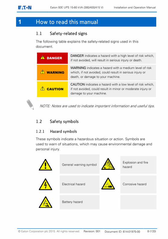
The following table explains the safety-related signs used in this document.
DANGER DANGER indicates a hazard with a high level of risk which, if not avoided, will result in serious injury or death.
WARNING WARNING indicates a hazard with a medium level of risk which, if not avoided, could result in serious injury or death, or damage to your machine.
CAUTION CAUTION indicates a hazard with a low level of risk which, if not avoided, could result in minor or moderate injury or damage to your machine.
NOTE: Notes are used to indicate important information and useful tips.
1.2 Safety symbols
1.2.1 Hazard symbols
These symbols indicate a hazardous situation or action. Symbols are used to warn of situations, which may cause environmental damage and personal injury.
General warning symbol
Explosion and fire hazard
Electrical hazard
Corrosive hazard
Battery hazard
Eaton 93E UPS 15-80 kVA (380/400/415 V) Installation and Operation Manual
© Eaton Corporation plc 2015. All rights reserved. Revision: 001 Document ID: 614-01975-00 9 (133)
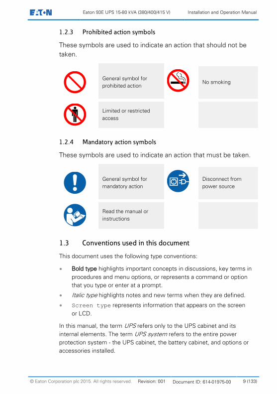
1.2.3 Prohibited action symbols
These symbols are used to indicate an action that should not be taken.
General symbol for prohibited action
No smoking
Limited or restricted access
1.2.4 Mandatory action symbols
These symbols are used to indicate an action that must be taken.
General symbol for mandatory action
Disconnect from power source
Read the manual or instructions
1.3 Conventions used in this document
This document uses the following type conventions:
• Bold type highlights important concepts in discussions, key terms in procedures and menu options, or represents a command or option that you type or enter at a prompt.
• Italic type highlights notes and new terms when they are defined.
• Screen type represents information that appears on the screen or LCD.
In this manual, the term UPS refers only to the UPS cabinet and its internal elements. The term UPS system refers to the entire power protection system - the UPS cabinet, the battery cabinet, and options or accessories installed.

Eaton 93E UPS 15-80 kVA (380/400/415 V) Installation and Operation Manual
© Eaton Corporation plc 2015. All rights reserved. Revision: 001 Document ID: 614-01975-00 10 (133)
The term line-up-and-match refers to cabinets that are physically attached to the UPS, and the wiring between them is internal. The term standalone refers to cabinets that are not physically attached to the UPS, and are wired with external contractor-supplied wiring.
Eaton 93E UPS 15-80 kVA (380/400/415 V) Installation and Operation Manual
© Eaton Corporation plc 2015. All rights reserved. Revision: 001 Document ID: 614-01975-00 11 (133)
2 Safety instructions
. DANGER
Important safety instructions!
Save these instructions!
This document contains important instructions that must be followed during the installation, operation and maintenance of the UPS and the batteries. Read all of the instructions before operating the equipment. Keep this manual for future reference.
The UPS operates with mains, battery or bypass power. It contains components that carry high currents and voltage. A properly installed enclosure is earthed and IP20 rated against electrical shock and foreign objects. However, the UPS is a sophisticated power system and only qualified personnel are allowed to install and service it.
. DANGER
This UPS carries lethal voltages. All repairs and service must be performed by authorized service personnel only. There are no user-serviceable parts inside the UPS.
. DANGER
Operations inside the UPS must be performed by a service engineer from the manufacturer or from an agent authorized by the manufacturer.
WARNING
The UPS is powered by its own energy source (batteries). The output terminals may carry live voltage even when the UPS is disconnected from an AC source.
Eaton 93E UPS 15-80 kVA (380/400/415 V) Installation and Operation Manual
© Eaton Corporation plc 2015. All rights reserved. Revision: 001 Document ID: 614-01975-00 12 (133)
WARNING
To reduce the risk of fire or electric shock, install the UPS in a temperature and humidity controlled, indoor environment that is free of conductive contaminants. The ambient temperature must not exceed 40 °C (104 °F). Do not operate near water or excessive humidity (95% maximum). The system is not intended for outdoor use.
As a result of the connected loads, high leakage current is possible. Connection to earth ground is required for safety and proper product operation. Do not check UPS operation by any action that includes removal of the earth (ground) connection.
Before you start any installation or service work, make sure that all AC and DC power sources are disconnected. Power may come from multiple sources.
When undertaking installation or service work, ensure system grounding continuity.
In a parallel system, the output terminals may be energized even when the UPS is turned off.
Batteries can present a risk of electrical shock or burn from high short circuit current. Always observe the following precautions when working with batteries: 1) Remove watches, rings, or other metal objects. 2) Use tools with proper insulation. 3) Do not lay tools or metal parts on top of batteries. 4) Wear rubber gloves and boots.
Electric energy hazard. Do not attempt to alter any battery cabling or connectors. Attempting to alter cabling can cause injury.
Do not open or mutilate batteries. Released electrolyte may be toxic and is harmful to the skin and eyes.
The UPS may be connected to TN and TT power distribution systems.
The UPS unit is not suitable for IT (Isolated neutral or impedance-earthed neutral) or corner-earthed power distribution systems.
IMPORTANT: The battery may consist of multiple parallel strings. Make sure that you disconnect all strings before installation.
Eaton 93E UPS 15-80 kVA (380/400/415 V) Installation and Operation Manual
© Eaton Corporation plc 2015. All rights reserved. Revision: 001 Document ID: 614-01975-00 13 (133)
CAUTION
Only qualified service personnel knowledgeable of the UPS and battery systems and the required precautions are allowed to perform installation or service work on batteries. Keep unauthorized personnel away from the equipment. Before you install or replace equipment, consider all the warnings, cautions, and notes concerning appropriate handling. Before you connect or disconnect batteries, make sure batteries are not being charged or discharged.
See the installation instructions before you connect the UPS to the supply.
Make sure that your replacement batteries are of the same number and type as the battery that was originally installed in the UPS. Replacing the battery with an incorrect type causes a risk of explosion.
This UPS uses floating battery circuit which must not be grounded.
Dispose of batteries according to your local disposal requirements. Do not dispose of batteries in a fire. When exposed to flame, batteries may explode.
To ensure proper cooling airflow and to protect personnel from dangerous voltages inside the unit, keep the UPS door closed and the front panels installed.
Do not install or operate the UPS system close to gas or electric heat sources.
Keep the operating environment within the parameters stated in this document. Keep the surroundings of the UPS uncluttered, clean, and free from excess moisture.
Observe all DANGER, CAUTION, and WARNING notices affixed to the inside and outside of the equipment.
Eaton 93E UPS 15-80 kVA (380/400/415 V) Installation and Operation Manual
© Eaton Corporation plc 2015. All rights reserved. Revision: 001 Document ID: 614-01975-00 14 (133)
2.1 Audience
The intended audience of this document is as follows:
• People who plan and perform the installation of the UPS
• People who use the UPS
This document provides guidelines for how to check the UPS delivery and how to install and operate the UPS.
The reader is expected to know the fundamentals of electricity, cabling, electrical components and electrical schematic symbols. This document is written for a global reader.
CAUTION
Read this document before you start to operate or perform work on the UPS.
2.2 CE marking
The product has a CE marking in compliance with the following European directives:
• LVD Directive (Safety) 2006/95/EC
• RoHS Directive 2011/65/EU
• EMC Directive 2004/108/EC
CAUTION
This is a product for commercial and industrial application in the second environment. Installation restrictions or additional measures may be needed to prevent disturbances.
2.3 User precautions
The only permitted user operations are as follows:
• Startup and shutdown of the UPS, excluding the commissioning startup.
• Use of the LCD control panel and the Maintenance Bypass Switch (MBS).
• Use of optional connectivity modules and their software.
Eaton 93E UPS 15-80 kVA (380/400/415 V) Installation and Operation Manual
© Eaton Corporation plc 2015. All rights reserved. Revision: 001 Document ID: 614-01975-00 15 (133)
Follow the precautions and only perform the described operations. Any deviation from the instructions can be dangerous to the user or cause accidental load loss.
. DANGER
Do not open any other screws in the unit than those holding the cover plates of the MiniSlots and the MBS locking plate. Failure to recognize the electrical hazards can prove fatal.
2.4 Environment
The UPS must be installed according to the recommendations in this document. Never install the UPS in an airtight room, in the presence of flammable gases, or in an environment exceeding the specifications.
Ensure sufficient amount of ventilation air flow preferably by natural ventilation. Otherwise, forced (artificial) ventilation must be implemented. Where forced ventilation is used, the air extracted from the battery room must be exhausted to the atmosphere outside the building.
The air inlet and outlet must be located at the best possible location to create ideal conditions for the exchange of air, i.e. with:
• Openings on the opposite walls
• A minimum separation distance of 2 meters when openings on the same wall
• It is recommended to locate the air inlet at the floor level and the air outlet close to the ceiling level.
• It is recommended to create an airflow scheme for installation of multiple UPSs.
• It is recommended to configure the installation layout with cold aisles and hot aisles due to the UPS front-to-rear airflow protocol.
• For the free cooling applications, the cooling plan based on the psychometric chart is highly recommended. The UPS specifications must not be exceeded.
Excessive amount of dust in the operating environment of the UPS may cause damage or lead to malfunction. Always protect the UPS from the outside weather and sunshine. In order to maximize internal battery
Eaton 93E UPS 15-80 kVA (380/400/415 V) Installation and Operation Manual
© Eaton Corporation plc 2015. All rights reserved. Revision: 001 Document ID: 614-01975-00 16 (133)
service life time, the recommended operating temperature range is from +20 ºC to +25 ºC. A temperature increase of 10 degrees reduces the life approximately by 50%. Batteries need mandatory air change according to the battery bank type, size and the charging current.
WARNING
During charge, float charge, heavy discharge, and overcharge, hydrogen and oxygen gases are emitted from lead-acid and NiCd batteries into the surrounding atmosphere. Explosive gas mixture may be created if the hydrogen concentration exceeds 4% by volume in air. Ensure the necessary air flow rate for the ventilation of the UPS location.
NOTE: For more information about the battery room ventilation requirements, including the calculation of the necessary air flow, see: IEC 62485-2: Safety requirements for secondary batteries and battery installations.
2.5 Using this manual
This manual describes how to install and operate the Eaton 93E 15-80 kVA. Read and understand the procedures described in this manual to ensure trouble-free installation and operation. In particular, be thoroughly familiar with the remote EPO procedure (see Section 7.3.13).
The information in this manual is divided into sections and chapters. The system, options, and accessories being installed dictate which parts of this manual should be read. At a minimum, Chapters 2 through 5 and Chapter 7 should be examined.
Read through each procedure before beginning the procedure. Perform only those procedures that apply to the UPS system being installed or operated.
Eaton 93E UPS 15-80 kVA (380/400/415 V) Installation and Operation Manual
© Eaton Corporation plc 2015. All rights reserved. Revision: 001 Document ID: 614-01975-00 17 (133)
2.6 Symbols on the UPS and accessories
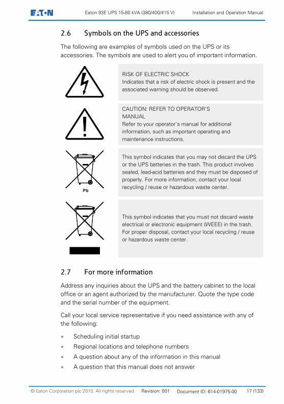
The following are examples of symbols used on the UPS or its accessories. The symbols are used to alert you of important information.
RISK OF ELECTRIC SHOCK Indicates that a risk of electric shock is present and the associated warning should be observed.
CAUTION: REFER TO OPERATOR'S MANUAL Refer to your operator's manual for additional information, such as important operating and maintenance instructions.
This symbol indicates that you may not discard the UPS or the UPS batteries in the trash. This product involves sealed, lead-acid batteries and they must be disposed of properly. For more information, contact your local recycling / reuse or hazardous waste center.
This symbol indicates that you must not discard waste electrical or electronic equipment (WEEE) in the trash. For proper disposal, contact your local recycling / reuse or hazardous waste center.
2.7 For more information
Address any inquiries about the UPS and the battery cabinet to the local office or an agent authorized by the manufacturer. Quote the type code and the serial number of the equipment.
Call your local service representative if you need assistance with any of the following:
• Scheduling initial startup
• Regional locations and telephone numbers
• A question about any of the information in this manual
• A question that this manual does not answer

Eaton 93E UPS 15-80 kVA (380/400/415 V) Installation and Operation Manual
© Eaton Corporation plc 2015. All rights reserved. Revision: 001 Document ID: 614-01975-00 18 (133)
Refer to the External Battery Cabinet Installation Manual for the following additional information:
• Installation instructions, including site preparation, planning for installation, cabling and safety information, and detailed illustrations of cabinets with dimensional and connection point drawings
Visit www.eaton.eu or contact an Eaton service representative for information on how to obtain copies of these manuals.
Eaton 93E UPS 15-80 kVA (380/400/415 V) Installation and Operation Manual
© Eaton Corporation plc 2015. All rights reserved. Revision: 001 Document ID: 614-01975-00 19 (133)
3 Introduction to Eaton UPS
The Eaton 93E 15-80 kVA uninterruptible power supply (UPS) is a true online, continuous-duty, transformer-free, double-conversion, solid-state, 3-phase system that provides conditioned and uninterruptible AC power to protect the loads connected to it from power failures.
The Eaton 93E 15-80 kVA online power protection system is used to prevent loss of valuable electronic information, minimise equipment downtime, and minimise the adverse effect on production equipment due to unexpected power problems.
The Eaton 93E 15-80 kVA UPS continually monitors incoming electrical power and removes the surges, spikes, sags, and other irregularities that are inherent in commercial utility power. Working with a building's electrical system, the UPS system supplies clean, consistent power that sensitive electronic equipment requires for reliable operation. During brownouts, blackouts, and other power anomalies, batteries provide emergency power to safeguard operation of the load equipment.
The UPS is housed in a single free-standing cabinet, with safety shields behind the door for hazardous voltage protection.
This manual is for Eaton 93E series UPS, refer Section 10.1 for product models.
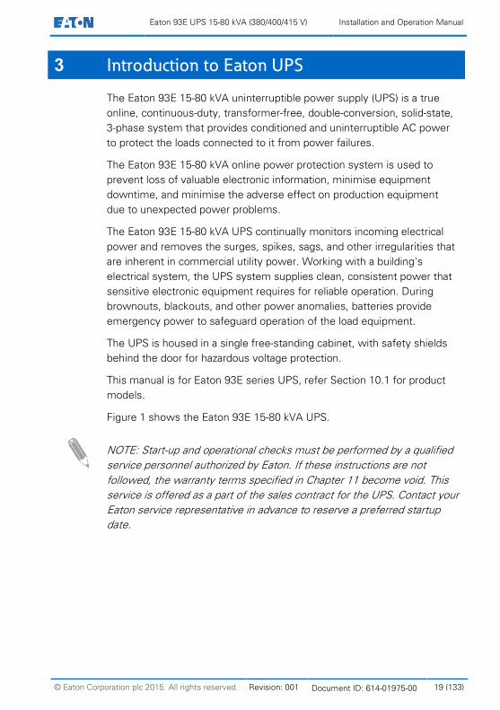
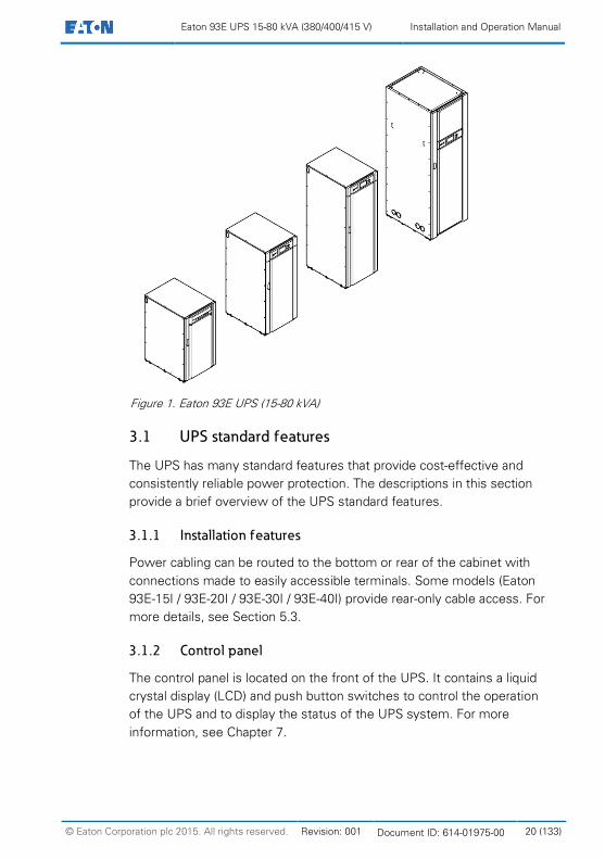
Figure 1 shows the Eaton 93E 15-80 kVA UPS.
NOTE: Start-up and operational checks must be performed by a qualified service personnel authorized by Eaton. If these instructions are not followed, the warranty terms specified in Chapter 11 become void. This service is offered as a part of the sales contract for the UPS. Contact your Eaton service representative in advance to reserve a preferred startup date.
Eaton 93E UPS 15-80 kVA (380/400/415 V) Installation and Operation Manual
© Eaton Corporation plc 2015. All rights reserved. Revision: 001 Document ID: 614-01975-00 20 (133)
Figure 1. Eaton 93E UPS (15-80 kVA)
3.1 UPS standard features
The UPS has many standard features that provide cost-effective and consistently reliable power protection. The descriptions in this section provide a brief overview of the UPS standard features.
3.1.1 Installation features
Power cabling can be routed to the bottom or rear of the cabinet with connections made to easily accessible terminals. Some models (Eaton 93E-15I / 93E-20I / 93E-30I / 93E-40I) provide rear-only cable access. For more details, see Section 5.3.
3.1.2 Control panel
The control panel is located on the front of the UPS. It contains a liquid crystal display (LCD) and push button switches to control the operation of the UPS and to display the status of the UPS system. For more information, see Chapter 7.
Eaton 93E UPS 15-80 kVA (380/400/415 V) Installation and Operation Manual
© Eaton Corporation plc 2015. All rights reserved. Revision: 001 Document ID: 614-01975-00 21 (133)
3.1.3 Communication interface
• Signal input monitoring
Up to 3 inputs in the UPS are available to connect the facility's alarm system contacts. Some system configurations may limit the number of inputs available. The UPS uses these inputs to monitor the signal inputs in addition to the UPS status. For more information, see Chapter 8.
• MiniSlot communication bays
2 communication bays are standard equipment. One to 2 optional MiniSlot connectivity cards can be installed in the UPS module at any time. MiniSlot cards are quickly installed at the front of the UPS (behind the door) and are hot-pluggable. For more information, see Chapter 8.
3.1.4 High-efficiency mode
The Eaton 93E Series UPS offers a high-efficiency (HE) normal mode with double-conversion on demand. This mode allows the Eaton 93E UPS to achieve 98% efficiency while still protecting the load. For information on how to set the UPS to work in the high efficiency mode, see Chapter 7.
3.1.5 Advanced Battery Management
A 3-stage charging system increases the battery service life by optimizing the recharge time. It also protects the batteries from damage due to high current charging and inverter ripple currents.
3.1.6 Maintenance bypass
The internal maintenance bypass for the 15-80 kVA models consists of input, output, neutral and bypass input (dual feeds) switches used to control the AC input to the UPS. The inverter output and the maintenance bypass switch are used to partially isolate the UPS so that a limited number of components can be serviced without interrupting power to the critical systems.
3.2 Options and accessories
Contact your Eaton sales representative for more information about the available options and accessories.
Eaton 93E UPS 15-80 kVA (380/400/415 V) Installation and Operation Manual
© Eaton Corporation plc 2015. All rights reserved. Revision: 001 Document ID: 614-01975-00 22 (133)
3.2.1 External battery cabinet
Battery backup protection is provided by equipping the UPS system with up to 4 external battery cabinets (EBCs) containing sealed lead-acid, maintenance-free batteries. An EBC is a single, free-standing cabinet designed to be installed as a part of a UPS system, but may be installed separate from the UPS cabinet.
3.2.2 Parallel system
A parallel UPS system with up to 4 UPSs can be installed to provide a parallel capacity and/or redundant system. This load sharing system provides more capacity than a single UPS, and can provide redundancy, depending on the load and configuration. In addition, when one UPS is taken out of service for maintenance or is not operating properly, a redundant UPS continues to supply uninterrupted power to the critical load. A Controller Area Network (CAN) bridge provides connectivity for system metering and operational mode control. The parallel system consists of 2 to 4 UPSs each with a parallel CAN bridge, and a tie cabinet or system parallel module to act as a tie point and to control the output.
Module output breakers (MOBs) allow the output of a UPS to be disconnected from other UPSs and the system load for maintenance and service. Design considerations assume that each UPS has a module output breaker (MOB). The breaker should also disconnect the neutral for improved safety during maintenance.
The MOB must have at least one normally open (N.O.) and one normally closed (N.C.) contact. These contacts must not share a common terminal. The N.C. contact is connected to the corresponding UPS’s input used for signal input. The N.O. contact is used to disconnect the bypass pull-chain when the MOB is open. Figure 24 and Figure 25 show the principles of paralleled UPS systems including MOBs and outputs from UPSs.
3.2.3 Monitoring and communication
Optional MiniSlot cards support several alternative communication interfaces, such as WEB/SNMP, RELAY / RS-232 and Modbus. For more information on the monitoring and communication features, see Chapter 8.
Eaton 93E UPS 15-80 kVA (380/400/415 V) Installation and Operation Manual
© Eaton Corporation plc 2015. All rights reserved. Revision: 001 Document ID: 614-01975-00 23 (133)
3.2.4 Single feed
The Eaton 93E 15-80 kVA standard models come with dual feed, requiring a separate feed for both rectifier and bypass input. Single feed kits are provided with each unit for on-site installation.
3.3 Battery system
Depending on the UPS model, the battery system may be internal or external. The battery system provides emergency short-term backup power to safeguard the operation during brownouts, blackouts, and other commercial power anomalies. The battery system is equipped with lead-acid batteries.
3.4 Basic system configurations
The following basic UPS system configurations are possible (depending on the model):
• UPS (internal battery).
• UPS with an external battery.
• UPS with external batteries and accessory cabinets
Up to 4 UPS's can be added in parallel for capacity or redundancy. The UPS system configuration can be enhanced by adding optional accessories, such as a remote Emergency Power-off (EPO) control or MiniSlot communication cards.
Eaton 93E UPS 15-80 kVA (380/400/415 V) Installation and Operation Manual
© Eaton Corporation plc 2015. All rights reserved. Revision: 001 Document ID: 614-01975-00 24 (133)
4 UPS installation plan and unpacking
Use the following basic sequence of steps to install the UPS:
1. Create an installation plan for the UPS system.
2. Prepare your site for the UPS system.
3. Inspect and unpack the UPS cabinet.
4. Unload and install the UPS cabinet and wire the system.
5. Complete the installation checklist provided in Section 4.2.
6. Have authorized service personnel perform the preliminary operational checks and startup.
NOTE: Startup and operational checks for parallel systems or installations with accessory cabinets must be performed by an authorized Eaton Customer Service Engineer, or the warranty terms specified in the Warranty (see Chapter 11) become void. This service is offered as a part of the sales contract for the UPS. Contact an Eaton service representative in advance (usually a 2-week notice is required) to reserve a preferred startup date.
WARNING
Only qualified technicians or electricians are allowed to carry out the installation. The installation must also be done according to the applicable safety standards.
Do not open any covers in the UPS. There are no user-serviceable parts inside the UPS.
The UPS unit is not suitable for IT (Isolated neutral or impedance-earthed neutral) or corner-earthed power distribution systems.
During installation, make sure that no line input source can accidentally be connected to the UPS.
Eaton 93E UPS 15-80 kVA (380/400/415 V) Installation and Operation Manual
© Eaton Corporation plc 2015. All rights reserved. Revision: 001 Document ID: 614-01975-00 25 (133)
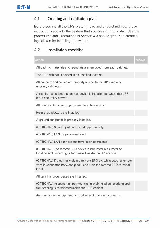
4.1 Creating an installation plan
Before you install the UPS system, read and understand how these instructions apply to the system that you are going to install. Use the procedures and illustrations in Section 4.3 and Chapter 5 to create a logical plan for installing the system.
4.2 Installation checklist
Action Yes/No
All packing materials and restraints are removed from each cabinet.
The UPS cabinet is placed in its installed location.
All conduits and cables are properly routed to the UPS and any ancillary cabinets.
A readily accessible disconnect device is installed between the UPS input and utility power.
All power cables are properly sized and terminated.
Neutral conductors are installed.
A ground conductor is properly installed.
(OPTIONAL) Signal inputs are wired appropriately.
(OPTIONAL) LAN drops are installed.
(OPTIONAL) LAN connections have been completed.
(OPTIONAL) The remote EPO device is mounted in its installed location and its cabling is terminated inside the UPS cabinet.
(OPTIONAL) If a normally-closed remote EPO switch is used, a jumper wire is connected between pins 3 and 4 on the remote EPO terminal block.
All terminal cover plates are installed.
(OPTIONAL) Accessories are mounted in their installed locations and their cabling is terminated inside the UPS cabinet.
Air conditioning equipment is installed and operating correctly.
Eaton 93E UPS 15-80 kVA (380/400/415 V) Installation and Operation Manual
© Eaton Corporation plc 2015. All rights reserved. Revision: 001 Document ID: 614-01975-00 26 (133)
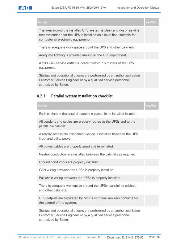
Action Yes/No
The area around the installed UPS system is clean and dust-free (it is recommended that the UPS is installed on a level floor suitable for computer or electronic equipment).
There is adequate workspace around the UPS and other cabinets.
Adequate lighting is provided around all the UPS equipment.
A 230 VAC service outlet is located within 7.5 meters of the UPS equipment.
Startup and operational checks are performed by an authorized Eaton Customer Service Engineer or by a qualified service personnel authorized by Eaton.
4.2.1 Parallel system installation checklist
Action Yes/No
Each cabinet in the parallel system is placed in its installed location.
All conduits and cables are properly routed to the UPSs and to the parallel tie cabinet.
A readily accessible disconnect device is installed between the UPS input and utility power.
All power cables are properly sized and terminated.
Neutral conductors are installed between the cabinets as required.
Ground conductors are properly installed.
CAN wiring between the UPSs is properly installed.
Pull chain wiring between the UPSs is properly installed.
There is adequate workspace around the UPSs, parallel tie cabinet, and other cabinets.
UPS outputs are separated by MOBs with dual auxiliary contacts for the control of the system.
Startup and operational checks are performed by an authorized Eaton Customer Service Engineer or by a qualified service personnel authorized by Eaton.
Eaton 93E UPS 15-80 kVA (380/400/415 V) Installation and Operation Manual
© Eaton Corporation plc 2015. All rights reserved. Revision: 001 Document ID: 614-01975-00 27 (133)
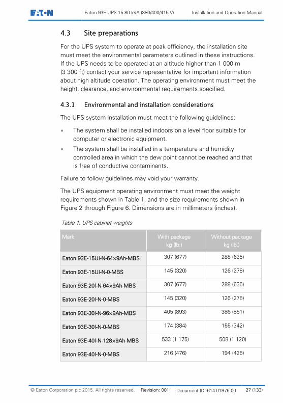
4.3 Site preparations
For the UPS system to operate at peak efficiency, the installation site must meet the environmental parameters outlined in these instructions. If the UPS needs to be operated at an altitude higher than 1 000 m (3 300 ft) contact your service representative for important information about high altitude operation. The operating environment must meet the height, clearance, and environmental requirements specified.
4.3.1 Environmental and installation considerations
The UPS system installation must meet the following guidelines:
• The system shall be installed indoors on a level floor suitable for computer or electronic equipment.
• The system shall be installed in a temperature and humidity controlled area in which the dew point cannot be reached and that is free of conductive contaminants.
Failure to follow guidelines may void your warranty.
The UPS equipment operating environment must meet the weight requirements shown in Table 1, and the size requirements shown in Figure 2 through Figure 6. Dimensions are in millimeters (inches).
Table 1. UPS cabinet weights
Mark With package kg (lb.)
Without package kg (lb.)
Eaton 93E-15UI-N-64×9Ah-MBS 307 (677) 288 (635)
Eaton 93E-15UI-N-0-MBS 145 (320) 126 (278)
Eaton 93E-20I-N-64×9Ah-MBS 307 (677) 288 (635)
Eaton 93E-20I-N-0-MBS 145 (320) 126 (278)
Eaton 93E-30I-N-96×9Ah-MBS 405 (893) 386 (851)
Eaton 93E-30I-N-0-MBS 174 (384) 155 (342)
Eaton 93E-40I-N-128×9Ah-MBS 533 (1 175) 508 (1 120)
Eaton 93E-40I-N-0-MBS 216 (476) 194 (428)
Eaton 93E UPS 15-80 kVA (380/400/415 V) Installation and Operation Manual
© Eaton Corporation plc 2015. All rights reserved. Revision: 001 Document ID: 614-01975-00 28 (133)
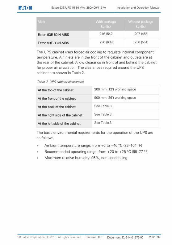
Mark With package kg (lb.)
Without package kg (lb.)
Eaton 93E-60-N-MBS 246 (542) 207 (456)
Eaton 93E-80-N-MBS 290 (639) 250 (551)
The UPS cabinet uses forced air cooling to regulate internal component temperature. Air inlets are in the front of the cabinet and outlets are at the rear of the cabinet. Allow clearance in front of and behind the cabinet for proper air circulation. The clearances required around the UPS cabinet are shown in Table 2.
Table 2. UPS cabinet clearances
At the top of the cabinet 300 mm (12") working space
At the front of the cabinet 900 mm (36") working space
At the back of the cabinet See Table 3.
At the right side of the cabinet See Table 3.
At the left side of the cabinet See Table 3.
The basic environmental requirements for the operation of the UPS are as follows:
• Ambient temperature range: from +0 to +40 °C (32–104 °F)
• Recommended operating range: from +20 to +25 °C (68–77 °F)
• Maximum relative humidity: 95%, non-condensing
Eaton 93E UPS 15-80 kVA (380/400/415 V) Installation and Operation Manual
© Eaton Corporation plc 2015. All rights reserved. Revision: 001 Document ID: 614-01975-00 29 (133)
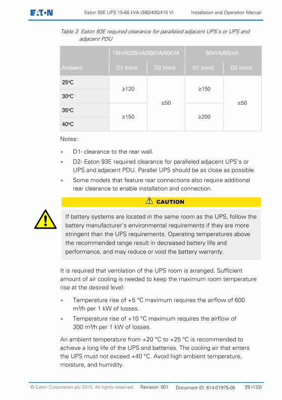
Table 3. Eaton 93E required clearance for paralleled adjacent UPS's or UPS and adjacent PDU
15kVA/20kVA/30kVA/40kVA 60kVA/80kVA
Ambient D1 (mm) D2 (mm) D1 (mm) D2 (mm)
25oC ≥120
≤50
≥150
≤50 30oC
35oC ≥150 ≥200
40oC
Notes:
• D1- clearance to the rear wall.
• D2- Eaton 93E required clearance for paralleled adjacent UPS's or UPS and adjacent PDU. Parallel UPS should be as close as possible.
• Some models that feature rear connections also require additional rear clearance to enable installation and connection.
CAUTION
If battery systems are located in the same room as the UPS, follow the battery manufacturer's environmental requirements if they are more stringent than the UPS requirements. Operating temperatures above the recommended range result in decreased battery life and performance, and may reduce or void the battery warranty.
It is required that ventilation of the UPS room is arranged. Sufficient amount of air cooling is needed to keep the maximum room temperature rise at the desired level:
• Temperature rise of +5 °C maximum requires the airflow of 600 m³/h per 1 kW of losses.
• Temperature rise of +10 °C maximum requires the airflow of 300 m³/h per 1 kW of losses.
An ambient temperature from +20 °C to +25 °C is recommended to achieve a long life of the UPS and batteries. The cooling air that enters the UPS must not exceed +40 °C. Avoid high ambient temperature, moisture, and humidity.
Eaton 93E UPS 15-80 kVA (380/400/415 V) Installation and Operation Manual
© Eaton Corporation plc 2015. All rights reserved. Revision: 001 Document ID: 614-01975-00 30 (133)
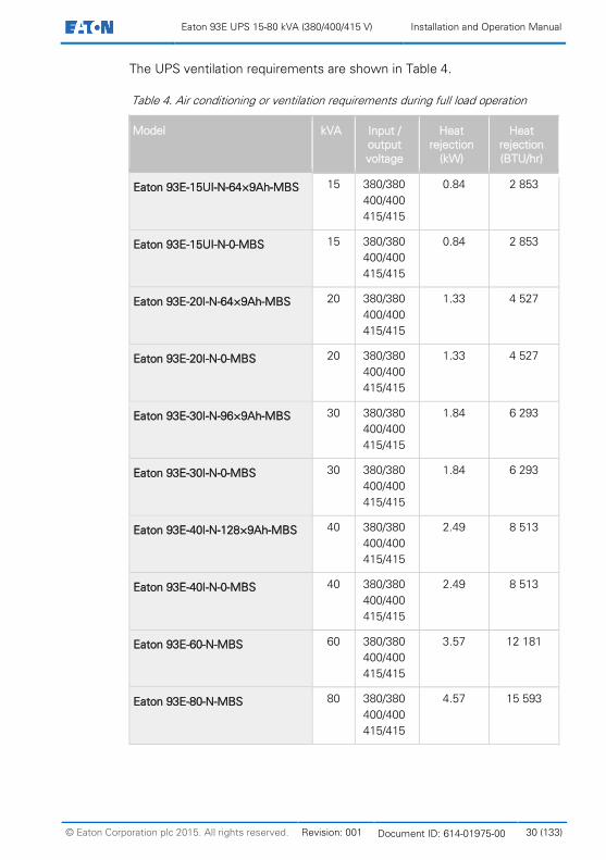
The UPS ventilation requirements are shown in Table 4.
Table 4. Air conditioning or ventilation requirements during full load operation
Model kVA Input / output voltage
Heat rejection
(kW)
Heat rejection (BTU/hr)
Eaton 93E-15UI-N-64×9Ah-MBS 15 380/380 400/400 415/415
0.84 2 853
Eaton 93E-15UI-N-0-MBS 15 380/380 400/400 415/415
0.84 2 853
Eaton 93E-20I-N-64×9Ah-MBS 20 380/380 400/400 415/415
1.33 4 527
Eaton 93E-20I-N-0-MBS 20 380/380 400/400 415/415
1.33 4 527
Eaton 93E-30I-N-96×9Ah-MBS 30 380/380 400/400 415/415
1.84 6 293
Eaton 93E-30I-N-0-MBS 30 380/380 400/400 415/415
1.84 6 293
Eaton 93E-40I-N-128×9Ah-MBS 40 380/380 400/400 415/415
2.49 8 513
Eaton 93E-40I-N-0-MBS 40 380/380 400/400 415/415
2.49 8 513
Eaton 93E-60-N-MBS 60 380/380 400/400 415/415
3.57 12 181
Eaton 93E-80-N-MBS 80 380/380 400/400 415/415
4.57 15 593
Eaton 93E UPS 15-80 kVA (380/400/415 V) Installation and Operation Manual
© Eaton Corporation plc 2015. All rights reserved. Revision: 001 Document ID: 614-01975-00 31 (133)
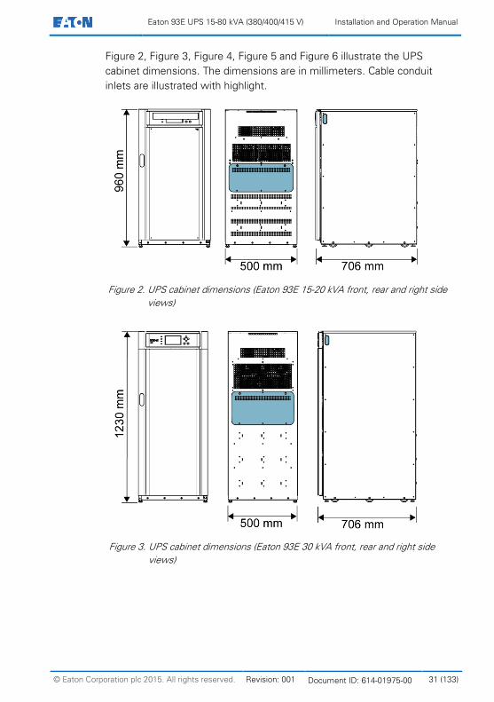
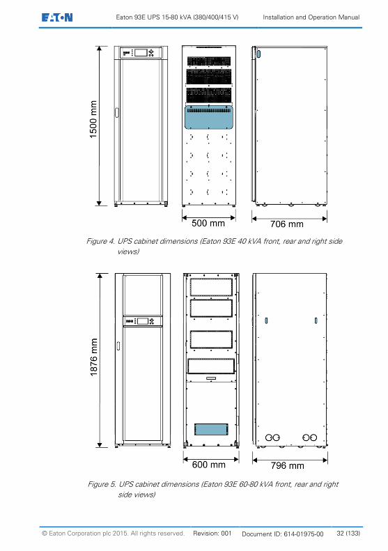
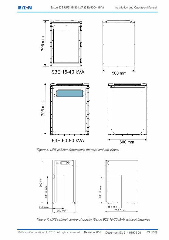
Figure 2, Figure 3, Figure 4, Figure 5 and Figure 6 illustrate the UPS cabinet dimensions. The dimensions are in millimeters. Cable conduit inlets are illustrated with highlight.
Figure 2. UPS cabinet dimensions (Eaton 93E 15-20 kVA front, rear and right side
views)
Figure 3. UPS cabinet dimensions (Eaton 93E 30 kVA front, rear and right side
views)
Eaton 93E UPS 15-80 kVA (380/400/415 V) Installation and Operation Manual
© Eaton Corporation plc 2015. All rights reserved. Revision: 001 Document ID: 614-01975-00 32 (133)
Figure 4. UPS cabinet dimensions (Eaton 93E 40 kVA front, rear and right side
views)
Figure 5. UPS cabinet dimensions (Eaton 93E 60-80 kVA front, rear and right
side views)
Eaton 93E UPS 15-80 kVA (380/400/415 V) Installation and Operation Manual
© Eaton Corporation plc 2015. All rights reserved. Revision: 001 Document ID: 614-01975-00 33 (133)
Figure 6. UPS cabinet dimensions (bottom and top views)
Figure 7. UPS cabinet centre of gravity (Eaton 93E 15-20 kVA) without batteries
Eaton 93E UPS 15-80 kVA (380/400/415 V) Installation and Operation Manual
© Eaton Corporation plc 2015. All rights reserved. Revision: 001 Document ID: 614-01975-00 34 (133)
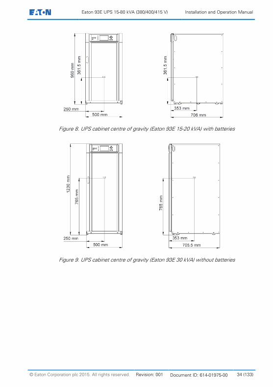
Figure 8. UPS cabinet centre of gravity (Eaton 93E 15-20 kVA) with batteries
Figure 9. UPS cabinet centre of gravity (Eaton 93E 30 kVA) without batteries
Eaton 93E UPS 15-80 kVA (380/400/415 V) Installation and Operation Manual
© Eaton Corporation plc 2015. All rights reserved. Revision: 001 Document ID: 614-01975-00 35 (133)
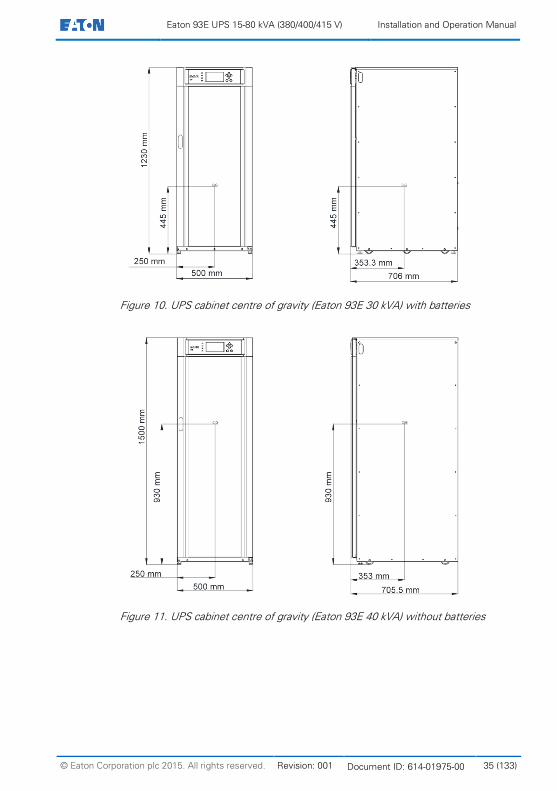
Figure 10. UPS cabinet centre of gravity (Eaton 93E 30 kVA) with batteries
Figure 11. UPS cabinet centre of gravity (Eaton 93E 40 kVA) without batteries
Eaton 93E UPS 15-80 kVA (380/400/415 V) Installation and Operation Manual
© Eaton Corporation plc 2015. All rights reserved. Revision: 001 Document ID: 614-01975-00 36 (133)
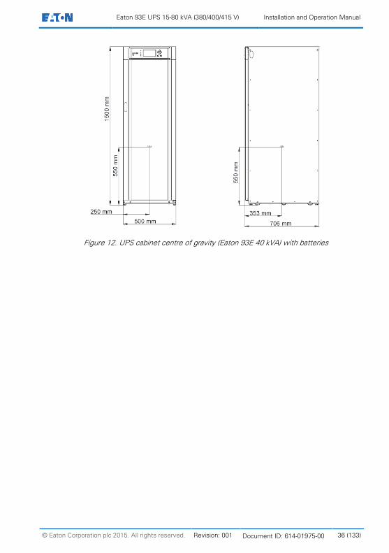
Figure 12. UPS cabinet centre of gravity (Eaton 93E 40 kVA) with batteries
Eaton 93E UPS 15-80 kVA (380/400/415 V) Installation and Operation Manual
© Eaton Corporation plc 2015. All rights reserved. Revision: 001 Document ID: 614-01975-00 37 (133)
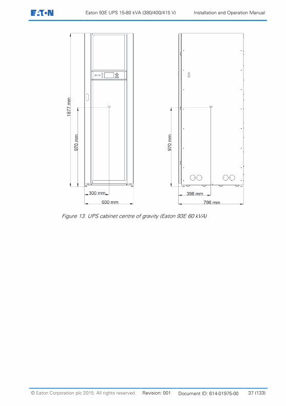
Figure 13. UPS cabinet centre of gravity (Eaton 93E 60 kVA)
Eaton 93E UPS 15-80 kVA (380/400/415 V) Installation and Operation Manual
© Eaton Corporation plc 2015. All rights reserved. Revision: 001 Document ID: 614-01975-00 38 (133)
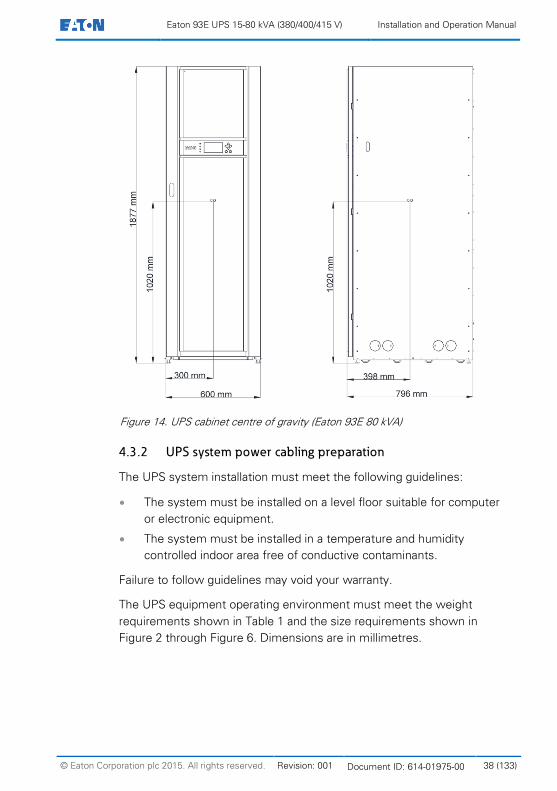
Figure 14. UPS cabinet centre of gravity (Eaton 93E 80 kVA)
4.3.2 UPS system power cabling preparation
The UPS system installation must meet the following guidelines:
• The system must be installed on a level floor suitable for computer or electronic equipment.
• The system must be installed in a temperature and humidity controlled indoor area free of conductive contaminants.
Failure to follow guidelines may void your warranty.
The UPS equipment operating environment must meet the weight requirements shown in Table 1 and the size requirements shown in Figure 2 through Figure 6. Dimensions are in millimetres.
Eaton 93E UPS 15-80 kVA (380/400/415 V) Installation and Operation Manual
© Eaton Corporation plc 2015. All rights reserved. Revision: 001 Document ID: 614-01975-00 39 (133)
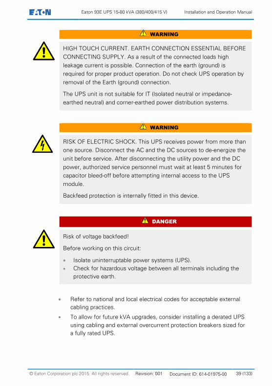
WARNING
HIGH TOUCH CURRENT. EARTH CONNECTION ESSENTIAL BEFORE CONNECTING SUPPLY. As a result of the connected loads high leakage current is possible. Connection of the earth (ground) is required for proper product operation. Do not check UPS operation by removal of the Earth (ground) connection.
The UPS unit is not suitable for IT (Isolated neutral or impedance-earthed neutral) and corner-earthed power distribution systems.
WARNING
RISK OF ELECTRIC SHOCK. This UPS receives power from more than one source. Disconnect the AC and the DC sources to de-energize the unit before service. After disconnecting the utility power and the DC power, authorized service personnel must wait at least 5 minutes for capacitor bleed-off before attempting internal access to the UPS module.
Backfeed protection is internally fitted in this device.
. DANGER
Risk of voltage backfeed!
Before working on this circuit:
• Isolate uninterruptable power systems (UPS). • Check for hazardous voltage between all terminals including the
protective earth.
• Refer to national and local electrical codes for acceptable external cabling practices.
• To allow for future kVA upgrades, consider installing a derated UPS using cabling and external overcurrent protection breakers sized for a fully rated UPS.
Eaton 93E UPS 15-80 kVA (380/400/415 V) Installation and Operation Manual
© Eaton Corporation plc 2015. All rights reserved. Revision: 001 Document ID: 614-01975-00 40 (133)
• For external wiring, use a minimum of 70°C copper cable. Cable sizes listed Table 5 are for copper cable only. If cables are run in an ambient temperature greater than 30°C, higher temperature cable and/or larger size wire may be necessary. Cable sizes are based on using the specified breakers.
• If installing an external maintenance bypass, all feeds to the UPS including the Rectifier Input Breaker (RIB) (if installed) must have a service disconnect independent of the maintenance bypass power path. Most maintenance bypass solutions provide UPS input feeds derived from but isolated from the maintenance bypass power path. If the maintenance bypass solution being installed does not provide such functionality, DO NOT use a single feeder breaker to supply both the UPS and the maintenance bypass.
• The bypass feed into this equipment uses 5 wires (3 line conductors, a neutral conductor and a protective earthing conductor). The rectifier feed into this equipment uses 4 wires (3 line conductors and a protective earthing conductor). The phases must be symmetrical about ground (from a Wye/Star source) for proper equipment operation.
• Parallel UPS input cable size requirements and output cable size requirements from the UPSs to the tie cabinet are the same as those for single systems.
• This device is not equipped with its own mains separation device. Install a readily accessible disconnect device in all fixed input wiring.
• Install a proper 3-pole overcurrent disconnect device before connecting to the UPS. The disconnect device shall disconnect simultaneously all line conductors of the AC mains supply.
• Do not disconnect neutral. Neutral is required for system operation.
• If a disconnect device interrupts the neutral conductor, it shall simultaneously interrupt all line conductors.
• When single-phase current exceeds 100 A, switches of protective atmosphere must be equipped with arc-control device. It should be D-curve air switch with UL certification according to the customer requirement.
Eaton 93E UPS 15-80 kVA (380/400/415 V) Installation and Operation Manual
© Eaton Corporation plc 2015. All rights reserved. Revision: 001 Document ID: 614-01975-00 41 (133)
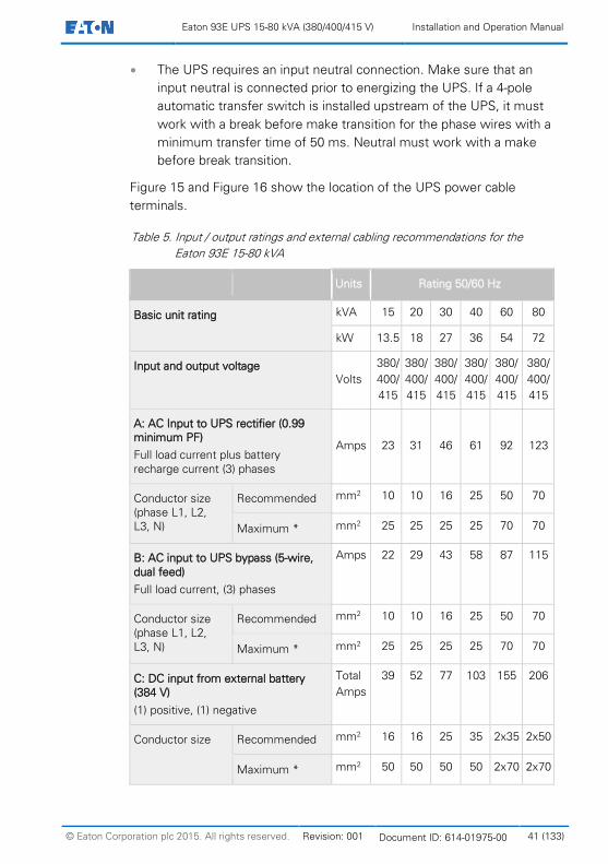
• The UPS requires an input neutral connection. Make sure that an input neutral is connected prior to energizing the UPS. If a 4-pole automatic transfer switch is installed upstream of the UPS, it must work with a break before make transition for the phase wires with a minimum transfer time of 50 ms. Neutral must work with a make before break transition.
Figure 15 and Figure 16 show the location of the UPS power cable terminals.
Table 5. Input / output ratings and external cabling recommendations for the Eaton 93E 15-80 kVA
Units Rating 50/60 Hz
Basic unit rating kVA 15 20 30 40 60 80
kW 13.5 18 27 36 54 72
Input and output voltage Volts
380/ 400/ 415
380/ 400/ 415
380/ 400/ 415
380/ 400/ 415
380/ 400/ 415
380/ 400/ 415
A: AC Input to UPS rectifier (0.99 minimum PF) Full load current plus battery recharge current (3) phases
Amps 23 31 46 61 92 123
Conductor size (phase L1, L2, L3, N)
Recommended mm2 10 10 16 25 50 70
Maximum * mm2 25 25 25 25 70 70
B: AC input to UPS bypass (5-wire, dual feed) Full load current, (3) phases
Amps 22 29 43 58 87 115
Conductor size (phase L1, L2, L3, N)
Recommended mm2 10 10 16 25 50 70
Maximum * mm2 25 25 25 25 70 70
C: DC input from external battery (384 V)
(1) positive, (1) negative
Total Amps
39 52 77 103 155 206
Conductor size Recommended mm2 16 16 25 35 2x35 2x50
Maximum * mm2 50 50 50 50 2x70 2x70
Eaton 93E UPS 15-80 kVA (380/400/415 V) Installation and Operation Manual
© Eaton Corporation plc 2015. All rights reserved. Revision: 001 Document ID: 614-01975-00 42 (133)
Units Rating 50/60 Hz
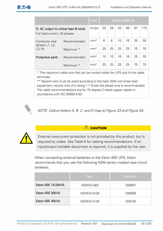
D: AC output to critical load (5-wire)
Full load current, (3) phases
Amps 22 29 43 58 87 115
Conductor size (phase L1, L2, L3, N)
Recommended mm2 6 6 10 16 35 50
Maximum * mm2 25 25 25 25 70 70
Protective earth Recommended mm2 10 10 16 16 25 35
Maximum * mm2 25 25 25 25 70 70
* The maximum cable size that can be routed inside the UPS and fit the cable terminals. ** Neutral wire must be sized according to the load. With non-linear load equipment, neutral wire of a rating 1.7 times the phase wire is recommended. The cable recommendations are for 70 degree C-rated copper cables in accordance with IEC 60364-5-52.
NOTE: Callout letters A, B, C, and D map to Figure 33 and Figure 34.
CAUTION
External overcurrent protection is not provided by this product, but is required by codes. See Table 5 for cabling recommendations. If an input/output lockable disconnect is required, it is supplied by the user.
When connecting external batteries to the Eaton 93E UPS, Eaton recommends that you use the following NZM series molded case circuit breakers:
Type Article no
Eaton 93E 15-20kVA NZMH2-A63 259097
Eaton 93E 30kVA NZMH2-A100 259099
Eaton 93E 40kVA NZMH2-A125 259100
Eaton 93E UPS 15-80 kVA (380/400/415 V) Installation and Operation Manual
© Eaton Corporation plc 2015. All rights reserved. Revision: 001 Document ID: 614-01975-00 43 (133)
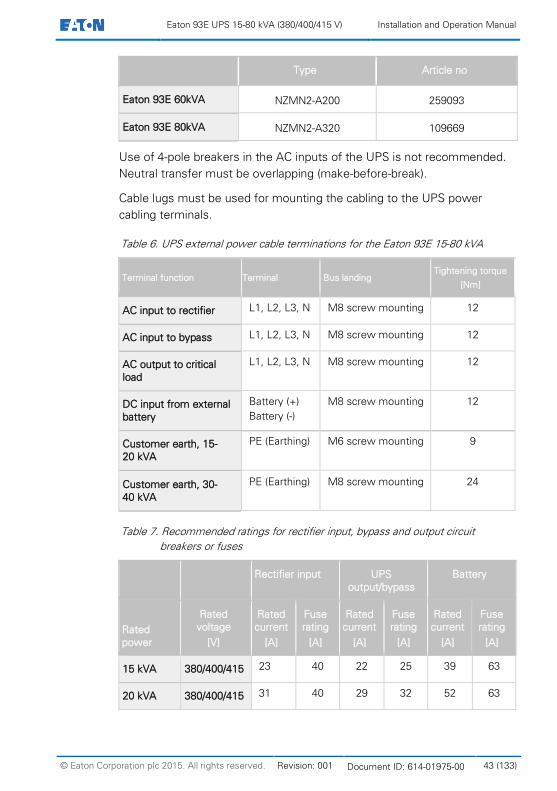
Type Article no
Eaton 93E 60kVA NZMN2-A200 259093
Eaton 93E 80kVA NZMN2-A320 109669
Use of 4-pole breakers in the AC inputs of the UPS is not recommended. Neutral transfer must be overlapping (make-before-break).
Cable lugs must be used for mounting the cabling to the UPS power cabling terminals.
Table 6. UPS external power cable terminations for the Eaton 93E 15-80 kVA
Terminal function Terminal Bus landing Tightening torque
[Nm]
AC input to rectifier L1, L2, L3, N M8 screw mounting 12
AC input to bypass L1, L2, L3, N M8 screw mounting 12
AC output to critical load
L1, L2, L3, N M8 screw mounting 12
DC input from external battery
Battery (+) Battery (-)
M8 screw mounting 12
Customer earth, 15-20 kVA
PE (Earthing) M6 screw mounting 9
Customer earth, 30-40 kVA
PE (Earthing) M8 screw mounting 24
Table 7. Recommended ratings for rectifier input, bypass and output circuit breakers or fuses
Rectifier input UPS output/bypass
Battery
Rated power
Rated voltage
[V]
Rated current
[A]
Fuse rating
[A]
Rated current
[A]
Fuse rating
[A]
Rated current
[A]
Fuse rating
[A]
15 kVA 380/400/415 23 40 22 25 39 63
20 kVA 380/400/415 31 40 29 32 52 63
Eaton 93E UPS 15-80 kVA (380/400/415 V) Installation and Operation Manual
© Eaton Corporation plc 2015. All rights reserved. Revision: 001 Document ID: 614-01975-00 44 (133)
Rectifier input UPS output/bypass
Battery
Rated power
Rated voltage
[V]
Rated current
[A]
Fuse rating
[A]
Rated current
[A]
Fuse rating
[A]
Rated current
[A]
Fuse rating
[A]
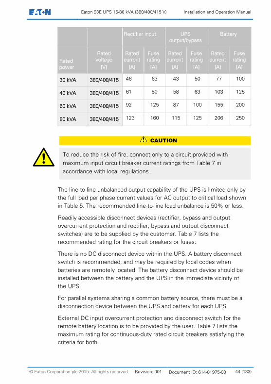
30 kVA 380/400/415 46 63 43 50 77 100
40 kVA 380/400/415 61 80 58 63 103 125
60 kVA 380/400/415 92 125 87 100 155 200
80 kVA 380/400/415 123 160 115 125 206 250
CAUTION
To reduce the risk of fire, connect only to a circuit provided with maximum input circuit breaker current ratings from Table 7 in accordance with local regulations.
The line-to-line unbalanced output capability of the UPS is limited only by the full load per phase current values for AC output to critical load shown in Table 5. The recommended line-to-line load unbalance is 50% or less.
Readily accessible disconnect devices (rectifier, bypass and output overcurrent protection and rectifier, bypass and output disconnect switches) are to be supplied by the customer. Table 7 lists the recommended rating for the circuit breakers or fuses.
There is no DC disconnect device within the UPS. A battery disconnect switch is recommended, and may be required by local codes when batteries are remotely located. The battery disconnect device should be installed between the battery and the UPS in the immediate vicinity of the UPS.
For parallel systems sharing a common battery source, there must be a disconnection device between the UPS and battery for each UPS.
External DC input overcurrent protection and disconnect switch for the remote battery location is to be provided by the user. Table 7 lists the maximum rating for continuous-duty rated circuit breakers satisfying the criteria for both.
Eaton 93E UPS 15-80 kVA (380/400/415 V) Installation and Operation Manual
© Eaton Corporation plc 2015. All rights reserved. Revision: 001 Document ID: 614-01975-00 45 (133)
Battery voltage is computed at 2 volts per cell. Rated battery current is computed at 2 volts per cell. The battery cabling used between the battery and the UPS should not allow a voltage drop of more than 1% of nominal DC voltage at rated battery current. If the conductors used for DC input from the battery cabinets to the UPS are those provided by the UPS manufacturer, and the UPS and battery cabinets are manufactured by the same supplier, then it is acceptable if they do not meet the noted minimum conductor sizes.
4.3.3 UPS system interface wiring preparation
Control wiring for features and options should be connected at the communication interface terminal blocks located inside the UPS.
WARNING
Do not connect relay contacts directly to the mains-related circuits. Reinforced insulation to the mains is required.
CAUTION
All the communication interfaces are SELV circuits. When connecting to other equipment, make sure that you maintain this characteristic.
Read and understand the following notes while planning and performing the installation:
• Interface wiring should be rated for a minimum of 24 V, 1A.
• For interface wiring from 30 V to 600 V, the wire should be rated for a minimum of 600 V, 1 A.
• Because of the remote EPO and signal input wiring route in the UPS cabinet, the wire should be rated for a minimum of 300 V.
• Use twisted-pair wires for each input and return or common.
• All interface wiring and conduit is provided by the operator.
• When installing external interface wiring between a remote EPO or signal input and the UPS interface terminals, conduit must be installed between each device and the UPS cabinet.
Eaton 93E UPS 15-80 kVA (380/400/415 V) Installation and Operation Manual
© Eaton Corporation plc 2015. All rights reserved. Revision: 001 Document ID: 614-01975-00 46 (133)
• If you are using the power terminal wiring channel, keep the interface wiring separate from the power wiring or use shielded wire.
• If using a conduit, install the interface wiring in a separate conduit from the power wiring.
• All signal inputs require an isolated normally-open contact or switch (rated at a minimum of 24 Vdc, 20 mA) connected between the alarm input and the common terminal. All control wiring and switch contacts are customer-supplied.
• LAN and telephone drops for use with MiniSlot connectivity cards must be supplied by the customer.
• The remote EPO feature opens all the relays in the UPS cabinet and isolates power from your critical load. Local electrical codes may also require tripping upstream protective devices to the UPS.
• The remote EPO switch must be a latching-type switch that is not tied to any other circuits.
• If you are using a normally-closed remote EPO switch, a jumper wire must be connected between pins 3 and 4 on the remote EPO terminal block.
• The remote EPO wiring should be a minimum of 0.5 mm² and a maximum of 2.0 mm².
• The remote EPO switch wiring must be in accordance with local regulations.
• The maximum distance between the remote EPO and the UPS must not exceed 150 metres (500 feet).
4.4 Inspecting and unpacking the UPS cabinets
The cabinet is shipped bolted onto a wooden pallet and protected with an outer wood container.
WARNING
The UPS cabinet is heavy (see Table 1). If you do not follow the unpacking and unloading instructions closely, the cabinet may tip and cause serious injury.
Eaton 93E UPS 15-80 kVA (380/400/415 V) Installation and Operation Manual
© Eaton Corporation plc 2015. All rights reserved. Revision: 001 Document ID: 614-01975-00 47 (133)
CAUTION
Do not install a damaged cabinet. Report any damage to the carrier and contact an Eaton service representative immediately.
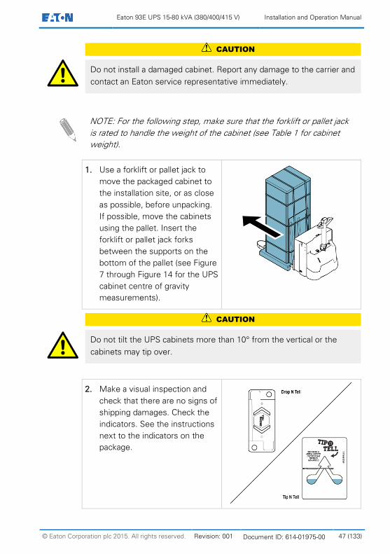
NOTE: For the following step, make sure that the forklift or pallet jack is rated to handle the weight of the cabinet (see Table 1 for cabinet weight).
1. Use a forklift or pallet jack to move the packaged cabinet to the installation site, or as close as possible, before unpacking. If possible, move the cabinets using the pallet. Insert the forklift or pallet jack forks between the supports on the bottom of the pallet (see Figure 7 through Figure 14 for the UPS cabinet centre of gravity measurements).
CAUTION
Do not tilt the UPS cabinets more than 10° from the vertical or the cabinets may tip over.
2. Make a visual inspection and check that there are no signs of shipping damages. Check the indicators. See the instructions next to the indicators on the package.
Eaton 93E UPS 15-80 kVA (380/400/415 V) Installation and Operation Manual
© Eaton Corporation plc 2015. All rights reserved. Revision: 001 Document ID: 614-01975-00 48 (133)
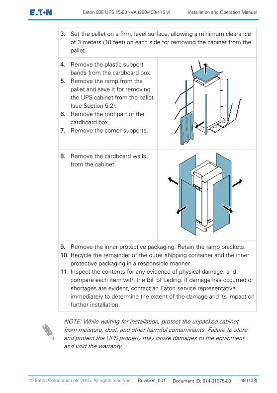
3. Set the pallet on a firm, level surface, allowing a minimum clearance of 3 meters (10 feet) on each side for removing the cabinet from the pallet.
4. Remove the plastic support bands from the cardboard box.
5. Remove the ramp from the pallet and save it for removing the UPS cabinet from the pallet (see Section 5.2).
6. Remove the roof part of the cardboard box.
7. Remove the corner supports.
8. Remove the cardboard walls
from the cabinet.
9. Remove the inner protective packaging. Retain the ramp brackets. 10. Recycle the remainder of the outer shipping container and the inner
protective packaging in a responsible manner. 11. Inspect the contents for any evidence of physical damage, and
compare each item with the Bill of Lading. If damage has occurred or shortages are evident, contact an Eaton service representative immediately to determine the extent of the damage and its impact on further installation.
NOTE: While waiting for installation, protect the unpacked cabinet from moisture, dust, and other harmful contaminants. Failure to store and protect the UPS properly may cause damages to the equipment and void the warranty.
Eaton 93E UPS 15-80 kVA (380/400/415 V) Installation and Operation Manual
© Eaton Corporation plc 2015. All rights reserved. Revision: 001 Document ID: 614-01975-00 49 (133)
5 UPS system installation
5.1 Preliminary installation information
The customer must supply the wiring to connect the UPS to the local power source. The electrical installation procedure is described in the following section. The installation inspection and the initial start-up of the UPS and installing an extra battery cabinet must be carried out by a qualified service personnel authorized by Eaton.
WARNING
Only qualified personnel are allowed to perform the installation. See the installation instructions before connecting to the supply.
Refer to the following while installing the UPS system:
• Chapter 3 for cabinet dimensions, equipment weight, cabling and terminal data, and installation notes.
Do not tilt the cabinets more than ±10° during the installation.
If perforated floor tiles are required for ventilation, place them in front of the UPS.
The UPS unit is not suitable for IT (Isolated neutral or impedance-earthed neutral) or corner-earthed power distribution systems.
5.2 Unloading the UPS cabinet from the pallet
The UPS cabinet is bolted to a wooden pallet supported by wooden skids. To remove the pallet:
WARNING
The UPS cabinet is heavy (see Table 1). If unpacking and unloading instructions are not closely followed, the cabinet may tip and cause serious injury.
Eaton 93E UPS 15-80 kVA (380/400/415 V) Installation and Operation Manual
© Eaton Corporation plc 2015. All rights reserved. Revision: 001 Document ID: 614-01975-00 50 (133)
CAUTION
Do not tilt cabinet more than 10° from vertical.
To prevent damages, lift the cabinets only with a forklift.
NOTE: For the following steps, make sure that the forklift or pallet jack is rated to handle the weight of the cabinet (see Table 1 for cabinet weight).
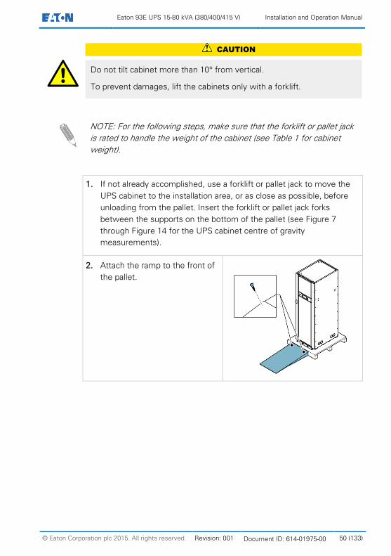
1. If not already accomplished, use a forklift or pallet jack to move the UPS cabinet to the installation area, or as close as possible, before unloading from the pallet. Insert the forklift or pallet jack forks between the supports on the bottom of the pallet (see Figure 7 through Figure 14 for the UPS cabinet centre of gravity measurements).
2. Attach the ramp to the front of the pallet.
Eaton 93E UPS 15-80 kVA (380/400/415 V) Installation and Operation Manual
© Eaton Corporation plc 2015. All rights reserved. Revision: 001 Document ID: 614-01975-00 51 (133)
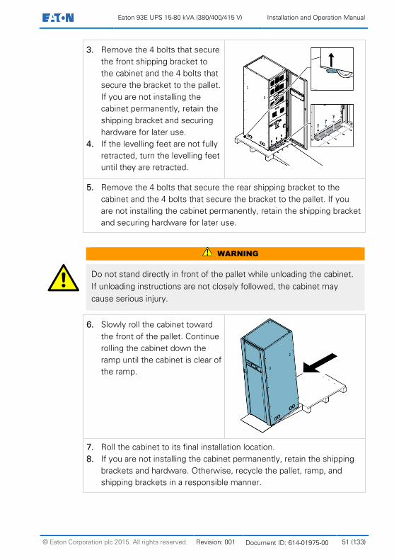
3. Remove the 4 bolts that secure the front shipping bracket to the cabinet and the 4 bolts that secure the bracket to the pallet. If you are not installing the cabinet permanently, retain the shipping bracket and securing hardware for later use.
4. If the levelling feet are not fully retracted, turn the levelling feet until they are retracted.
5. Remove the 4 bolts that secure the rear shipping bracket to the cabinet and the 4 bolts that secure the bracket to the pallet. If you are not installing the cabinet permanently, retain the shipping bracket and securing hardware for later use.
WARNING
Do not stand directly in front of the pallet while unloading the cabinet. If unloading instructions are not closely followed, the cabinet may cause serious injury.
6. Slowly roll the cabinet toward the front of the pallet. Continue rolling the cabinet down the ramp until the cabinet is clear of the ramp.
7. Roll the cabinet to its final installation location. 8. If you are not installing the cabinet permanently, retain the shipping
brackets and hardware. Otherwise, recycle the pallet, ramp, and shipping brackets in a responsible manner.
Eaton 93E UPS 15-80 kVA (380/400/415 V) Installation and Operation Manual
© Eaton Corporation plc 2015. All rights reserved. Revision: 001 Document ID: 614-01975-00 52 (133)
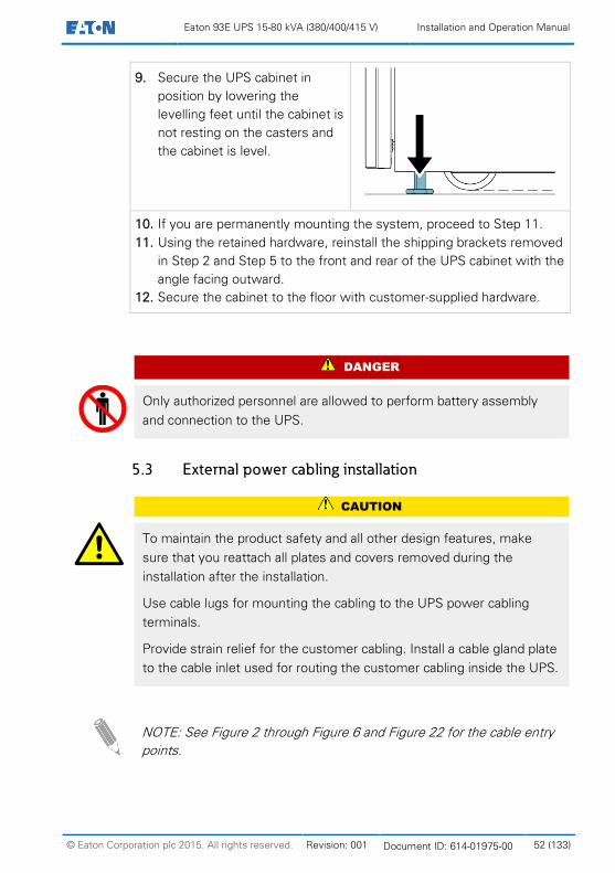
9. Secure the UPS cabinet in position by lowering the levelling feet until the cabinet is not resting on the casters and the cabinet is level.
10. If you are permanently mounting the system, proceed to Step 11. 11. Using the retained hardware, reinstall the shipping brackets removed
in Step 2 and Step 5 to the front and rear of the UPS cabinet with the angle facing outward.
12. Secure the cabinet to the floor with customer-supplied hardware.
0.
. DANGER
Only authorized personnel are allowed to perform battery assembly and connection to the UPS.
5.3 External power cabling installation
CAUTION
To maintain the product safety and all other design features, make sure that you reattach all plates and covers removed during the installation after the installation.
Use cable lugs for mounting the cabling to the UPS power cabling terminals.
Provide strain relief for the customer cabling. Install a cable gland plate to the cable inlet used for routing the customer cabling inside the UPS.
NOTE: See Figure 2 through Figure 6 and Figure 22 for the cable entry points.
Eaton 93E UPS 15-80 kVA (380/400/415 V) Installation and Operation Manual
© Eaton Corporation plc 2015. All rights reserved. Revision: 001 Document ID: 614-01975-00 53 (133)
To install wiring:
1. Remove the dead front and back plate from the UPS.
2. Route the cables to the UPS terminal blocks in the UPS through the cable entry point at the rear of the UPS cabinet. See Figure 15 and Figure 16 for cable access information and terminal locations.
3. Ground the UPS according to local and/or national electrical cabling codes by routing and connecting the ground cable to the grounding terminal.
4. Connect phase L1, L2 and L3 rectifier input power cabling from the utility source to the rectifier input, see Section 4.3.2 for cabling and termination requirements.
5. Connect phase L1, L2, L3 and neutral bypass input power cabling from the utility source to the bypass input terminals and neutral terminals. See Section 4.3.2 for cabling and termination requirements.
6. Connect phase L1, L2, L3 and neutral power wiring from the output terminals to the critical load. See Section 4.3.2 for wiring and termination requirements.
7. If you are wiring interface connections, proceed to Section 5.4.
8. Reinstall the dead front and back plate to the UPS
WARNING
High touch current! It is essential that you connect the earth before connecting the supply. As a result of the connected loads, high leakage current is possible. Connection of the earth (ground) is required for proper product operation. Do not check UPS operation by removing the earth (ground) connection.
BAT+ and BAT- are the terminals connected to the battery cabinet. Use red cable for Battery+ polarity and black or blue cable for Battery - polarity.
Connect the input neutral line directly to the input “N” terminal.
There are protective earthing terminals within the UPS for mains supply, load supply and battery. The battery cabinet earth connection shall be connected to the earthing terminal within the UPS.
Eaton 93E UPS 15-80 kVA (380/400/415 V) Installation and Operation Manual
© Eaton Corporation plc 2015. All rights reserved. Revision: 001 Document ID: 614-01975-00 54 (133)
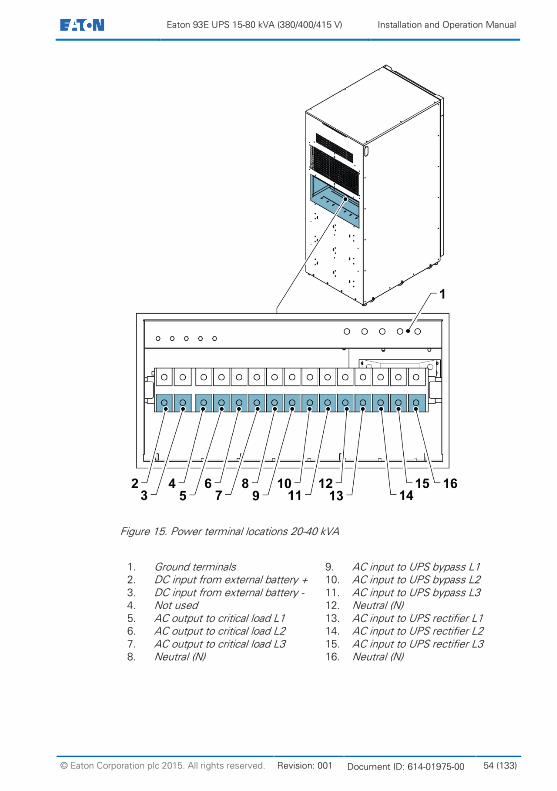
Figure 15. Power terminal locations 20-40 kVA
1. Ground terminals 2. DC input from external battery + 3. DC input from external battery - 4. Not used 5. AC output to critical load L1 6. AC output to critical load L2 7. AC output to critical load L3 8. Neutral (N)
9. AC input to UPS bypass L1 10. AC input to UPS bypass L2 11. AC input to UPS bypass L3 12. Neutral (N) 13. AC input to UPS rectifier L1 14. AC input to UPS rectifier L2 15. AC input to UPS rectifier L3 16. Neutral (N)
Eaton 93E UPS 15-80 kVA (380/400/415 V) Installation and Operation Manual
© Eaton Corporation plc 2015. All rights reserved. Revision: 001 Document ID: 614-01975-00 55 (133)
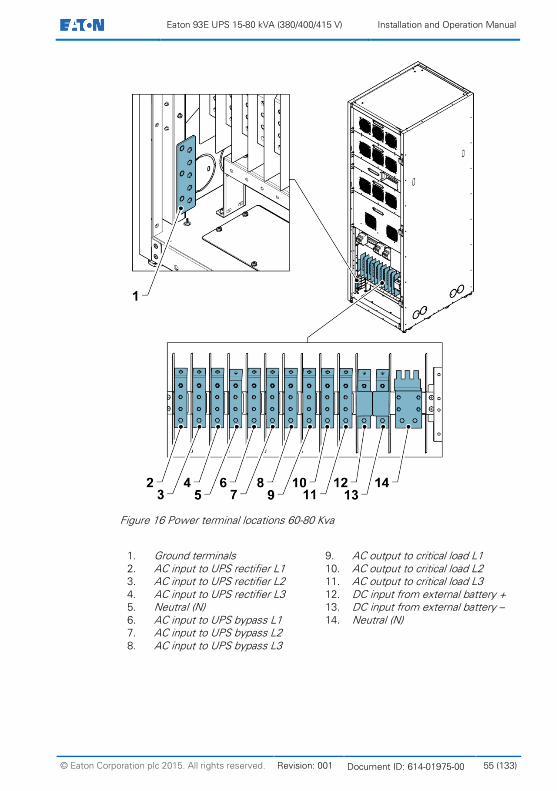
Figure 16 Power terminal locations 60-80 Kva
1. Ground terminals 2. AC input to UPS rectifier L1 3. AC input to UPS rectifier L2 4. AC input to UPS rectifier L3 5. Neutral (N) 6. AC input to UPS bypass L1 7. AC input to UPS bypass L2 8. AC input to UPS bypass L3
9. AC output to critical load L1 10. AC output to critical load L2 11. AC output to critical load L3 12. DC input from external battery + 13. DC input from external battery – 14. Neutral (N)
Eaton 93E UPS 15-80 kVA (380/400/415 V) Installation and Operation Manual
© Eaton Corporation plc 2015. All rights reserved. Revision: 001 Document ID: 614-01975-00 56 (133)
5.4 Battery system installation
. DANGER
This UPS may have internal batteries. The batteries are designed to deliver a large amount of energy and an incorrect connection may lead to a short circuit and cause serious injuries to the personnel or damages to the equipment. In order to avoid damages to the equipment or injuries to personnel, only commissioning personnel are allowed to perform the connection of these batteries.
If installing a customer-supplied battery system, install the battery system according to the battery and battery system manufacturer’s instructions and all the applicable national codes and regulations. Only qualified personnel may install the battery system. Battery cables must be protected against short circuit and overload, that is, the battery system must include proper fuses or breaker with protection function. Ground the external battery cabinet to the UPS.
In the models that contain internal batteries, internal battery circuit is open during transportation. The internal battery cabling must be connected before UPS start-up. Note that only commissioning personnel are allowed to perform the connection
NOTE: For more information about the installation space, safe operation and working, see Safety requirements for secondary batteries and battery installations IEC 62485-2.
Doors to battery rooms and cabinets must be marked with warning labels as follows:
• "Dangerous voltage", if the battery voltage is more than 60 V.
• Barring sign for "Fire, naked flames, smoking prohibited".
• Warning sign "Accumulator, Battery Room" to indicate corrosive electrolyte, explosive gases, dangerous voltages and currents.
Eaton 93E UPS 15-80 kVA (380/400/415 V) Installation and Operation Manual
© Eaton Corporation plc 2015. All rights reserved. Revision: 001 Document ID: 614-01975-00 57 (133)
5.4.1 External battery cabinet installation
NOTE: Do not connect external batteries to a UPS that contains internal batteries.
When Eaton 93E 15-80 kVA UPS is in battery mode, the power is provided by internal or external batteries. The UPS can be equipped with up to 4 external battery cabinets (EBCs) containing valve-regulated lead-acid (VRLA), maintenance-free batteries. The UPS has 32 batteries per string, if using internal batteries. A single EBC can contain 32-40 batteries per string. Power and control wiring are not supplied with the UPS.
When installing Eaton external battery cabinets (EBCs), refer to the manufacturer’s installation manual.
If installing a customer-supplied battery system, install the battery system according to the battery and battery system manufacturer’s instructions and all the applicable codes and regulations.
Cable entry to the UPS is at the rear of the UPS. External DC input overcurrent protection and disconnect switch for a remote battery location is to be provided by the user.
Before you connect the external battery, read the notice and warning label on the battery cabinet.
. DANGER
A single EBC for Eaton 93E 15-40kVA models contains 32 batteries per string and for Eaton 93E 60-80kVA models contains 32-40 blocks.
Eaton 93E UPS 15-80 kVA (380/400/415 V) Installation and Operation Manual
© Eaton Corporation plc 2015. All rights reserved. Revision: 001 Document ID: 614-01975-00 58 (133)
WARNING
In the event of a malfunction, the battery cabinet chassis or battery cabinet frames may become live!
Take special care when working with the battery cabinet associated with the equipment. Make sure that the battery number is suited to the setting of the battery charging voltage before installing the battery. When the battery cabinet is connected, the overall voltage exceeds nominal voltage. It is very important that you make sure that the batteries are installed separately, in a dedicated battery cabinet.
Do not exceed the battery back-up time of one hour.
CAUTION
The most common battery type used in UPS installations is the valve-regulated battery. Valve-regulated cells are not sealed. The amount of gas given off is less than for flooded cells, but when planning the battery installation, allowance must be made for adequate ventilation and heat dissipation.
Valve-regulated cells are not completely maintenance-free. They must be kept clean and their connections checked periodically to ensure that they are tight, and that there is no evidence of corrosion. The batteries lose charge during transportation and storage, so before you attempt to carry out an autonomy test, make sure that the batteries are fully charged as this may take several hours. Cell performance typically improves after a few discharge/recharge cycles.
The requirements of the EC directives are satisfied when battery cabinets are used with original accessories. If alternative batteries are used, make sure that the applicable EC directives are met and declare conformity.
Connect the battery cabinet as follows:
1. Turn off the UPS.
2. Check that all the external battery breakers are open.
3. Connect PE first.
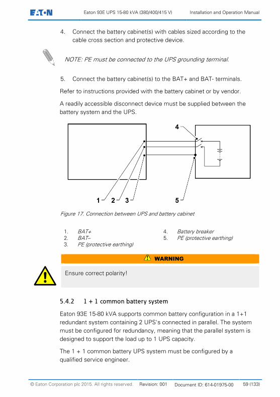
Eaton 93E UPS 15-80 kVA (380/400/415 V) Installation and Operation Manual
© Eaton Corporation plc 2015. All rights reserved. Revision: 001 Document ID: 614-01975-00 59 (133)
4. Connect the battery cabinet(s) with cables sized according to the cable cross section and protective device.
NOTE: PE must be connected to the UPS grounding terminal.
5. Connect the battery cabinet(s) to the BAT+ and BAT- terminals.
Refer to instructions provided with the battery cabinet or by vendor.
A readily accessible disconnect device must be supplied between the battery system and the UPS.
Figure 17. Connection between UPS and battery cabinet
1. BAT+ 2. BAT– 3. PE (protective earthing)
4. Battery breaker 5. PE (protective earthing)
WARNING
Ensure correct polarity!
5.4.2 1 + 1 common battery system
Eaton 93E 15-80 kVA supports common battery configuration in a 1+1 redundant system containing 2 UPS's connected in parallel. The system must be configured for redundancy, meaning that the parallel system is designed to support the load up to 1 UPS capacity.
The 1 + 1 common battery UPS system must be configured by a qualified service engineer.
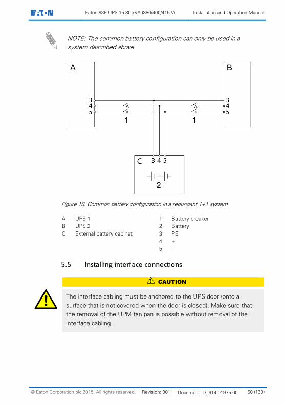
Eaton 93E UPS 15-80 kVA (380/400/415 V) Installation and Operation Manual
© Eaton Corporation plc 2015. All rights reserved. Revision: 001 Document ID: 614-01975-00 60 (133)
NOTE: The common battery configuration can only be used in a system described above.
Figure 18. Common battery configuration in a redundant 1+1 system
A UPS 1 1 Battery breaker B UPS 2 2 Battery C External battery cabinet 3 PE 4 + 5 -
5.5 Installing interface connections
CAUTION
The interface cabling must be anchored to the UPS door (onto a surface that is not covered when the door is closed). Make sure that the removal of the UPM fan pan is possible without removal of the interface cabling.
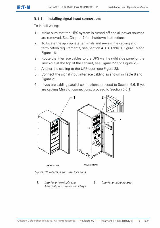
Eaton 93E UPS 15-80 kVA (380/400/415 V) Installation and Operation Manual
© Eaton Corporation plc 2015. All rights reserved. Revision: 001 Document ID: 614-01975-00 61 (133)
5.5.1 Installing signal input connections
To install wiring:
1. Make sure that the UPS system is turned off and all power sources are removed. See Chapter 7 for shutdown instructions.
2. To locate the appropriate terminals and review the cabling and termination requirements, see Section 4.3.3, Table 8, Figure 15 and Figure 16.
3. Route the interface cables to the UPS via the right side panel or the knockout at the top of the cabinet, see Figure 22 and Figure 23.
4. Anchor the cabling to the UPS door, see Figure 23.
5. Connect the signal input interface cabling as shown in Table 8 and Figure 21.
6. If you are cabling parallel connections, proceed to Section 5.6. If you are cabling MiniSlot connections, proceed to Section 5.6.1.
Figure 19. Interface terminal locations
1. Interface terminals and MiniSlot communications bays
2. Interface cable access
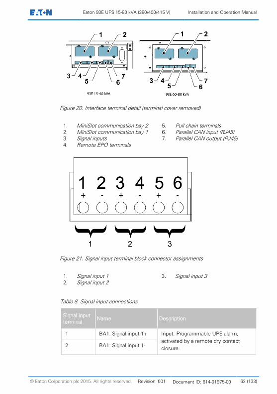
Eaton 93E UPS 15-80 kVA (380/400/415 V) Installation and Operation Manual
© Eaton Corporation plc 2015. All rights reserved. Revision: 001 Document ID: 614-01975-00 62 (133)
Figure 20. Interface terminal detail (terminal cover removed)
1. MiniSlot communication bay 2 2. MiniSlot communication bay 1 3. Signal inputs 4. Remote EPO terminals
5. Pull chain terminals 6. Parallel CAN input (RJ45) 7. Parallel CAN output (RJ45)
Figure 21. Signal input terminal block connector assignments
1. Signal input 1 2. Signal input 2
3. Signal input 3
Table 8. Signal input connections
Signal input terminal
Name Description
1 BA1: Signal input 1+ Input: Programmable UPS alarm, activated by a remote dry contact closure. 2 BA1: Signal input 1-
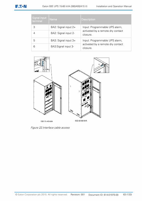
Eaton 93E UPS 15-80 kVA (380/400/415 V) Installation and Operation Manual
© Eaton Corporation plc 2015. All rights reserved. Revision: 001 Document ID: 614-01975-00 63 (133)
Signal input terminal
Name Description
3 BA2: Signal input 2+ Input: Programmable UPS alarm, activated by a remote dry contact closure. 4 BA2: Signal input 2-
5 BA3: Signal input 3+ Input: Programmable UPS alarm, activated by a remote dry contact closure. 6 BA3:Signal input 3-
Figure 22.Interface cable access
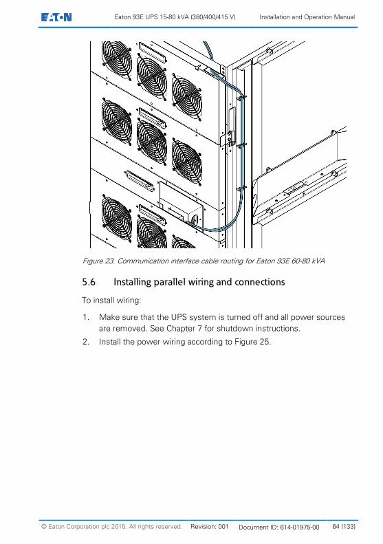
Eaton 93E UPS 15-80 kVA (380/400/415 V) Installation and Operation Manual
© Eaton Corporation plc 2015. All rights reserved. Revision: 001 Document ID: 614-01975-00 64 (133)
Figure 23. Communication interface cable routing for Eaton 93E 60-80 kVA
5.6 Installing parallel wiring and connections
To install wiring:
1. Make sure that the UPS system is turned off and all power sources are removed. See Chapter 7 for shutdown instructions.
2. Install the power wiring according to Figure 25.
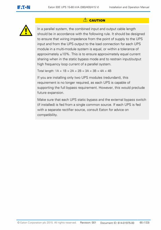
Eaton 93E UPS 15-80 kVA (380/400/415 V) Installation and Operation Manual
© Eaton Corporation plc 2015. All rights reserved. Revision: 001 Document ID: 614-01975-00 65 (133)
CAUTION
In a parallel system, the combined input and output cable length should be in accordance with the following rule. It should be designed to ensure that wiring impedance from the point of supply to the UPS input and from the UPS output to the load connection for each UPS module in a multi-module system is equal, or within a tolerance of approximately ±10%. This is to ensure approximately equal current sharing when in the static bypass mode and to restrain input/output high frequency loop current of a parallel system.
Total length: 1A + 1B = 2A + 2B = 3A + 3B = 4A + 4B
If you are installing only two UPS modules (redundant), this requirement is no longer required, as each UPS is capable of supporting the full bypass requirement. However, this would preclude future expansion.
Make sure that each UPS static bypass and the external bypass switch (if installed) is fed from a single common source. If each UPS is fed with a separate rectifier source, consult Eaton for advice on compatibility.
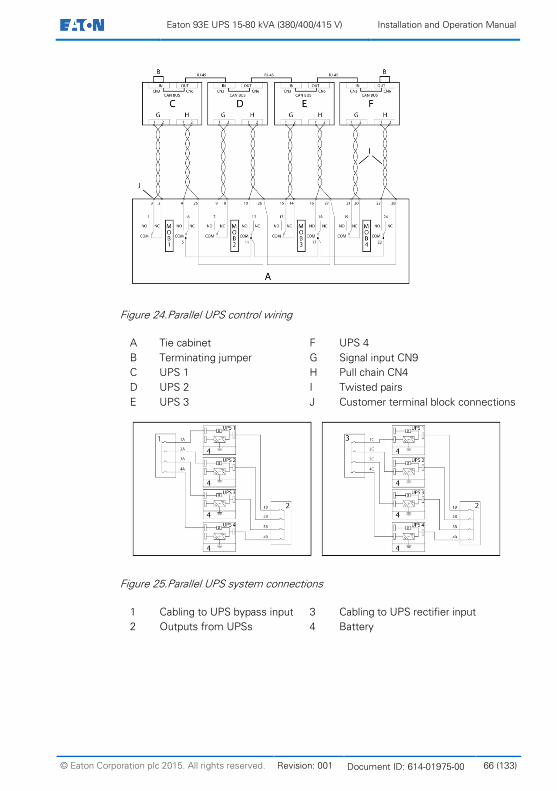
Eaton 93E UPS 15-80 kVA (380/400/415 V) Installation and Operation Manual
© Eaton Corporation plc 2015. All rights reserved. Revision: 001 Document ID: 614-01975-00 66 (133)
Figure 24.Parallel UPS control wiring
A Tie cabinet F UPS 4 B Terminating jumper G Signal input CN9 C UPS 1 H Pull chain CN4 D UPS 2 I Twisted pairs E UPS 3 J Customer terminal block connections
Figure 25.Parallel UPS system connections
1 Cabling to UPS bypass input 3 Cabling to UPS rectifier input 2 Outputs from UPSs 4 Battery
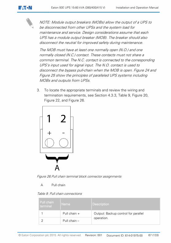
Eaton 93E UPS 15-80 kVA (380/400/415 V) Installation and Operation Manual
© Eaton Corporation plc 2015. All rights reserved. Revision: 001 Document ID: 614-01975-00 67 (133)
NOTE: Module output breakers (MOBs) allow the output of a UPS to be disconnected from other UPSs and the system load for maintenance and service. Design considerations assume that each UPS has a module output breaker (MOB). The breaker should also disconnect the neutral for improved safety during maintenance.
The MOB must have at least one normally open (N.O.) and one normally closed (N.C.) contact. These contacts must not share a common terminal. The N.C. contact is connected to the corresponding UPS’s input used for signal input. The N.O. contact is used to disconnect the bypass pull-chain when the MOB is open. Figure 24 and Figure 25 show the principles of paralleled UPS systems including MOBs and outputs from UPSs.
3. To locate the appropriate terminals and review the wiring and termination requirements, see Section 4.3.3, Table 9, Figure 20, Figure 22, and Figure 26.
Figure 26.Pull chain terminal block connector assignments
A Pull chain
Table 9. Pull chain connections
Pull chain terminal
Name Description
1 Pull chain + Output: Backup control for parallel operation.
2 Pull chain –
Eaton 93E UPS 15-80 kVA (380/400/415 V) Installation and Operation Manual
© Eaton Corporation plc 2015. All rights reserved. Revision: 001 Document ID: 614-01975-00 68 (133)
4. Remove the small parts from the knockout in the right side plate.
5. Route and install the RJ-45 Controller Area Network (CAN) cables between the UPS cabinets. See Figure 20, Figure 24 and Figure 25 for wiring information.
6. Route and install pull chain wiring (twisted wires 0.5-2.0 mm2) between the UPS cabinets and cabinet MOBs. See Figure 20, Figure 24 and Figure 26 for wiring information.
7. Anchor the cabling to the UPS door.
8. If you are wiring MiniSlot connections, proceed to Section 5.6.1.
5.6.1 Installing MiniSlot interface connections
NOTE: The LAN drop for connection to the UPS communications card is to be supplied by the customer.
For installation and setup of a MiniSlot card, contact an Eaton service representative (see Section 2.7)
To install wiring:
1. If not already installed, install the LAN drop.
2. Route and install the LAN and other cables to the appropriate MiniSlot cards. See Figure 19 and Figure 20 for the MiniSlot communication bay locations.
3. Anchor the cabling to the UPS door.
4. Refer to the manual supplied with the MiniSlot card for operator instructions.
5. Install the power terminal cover using the provided hardware.
5.7 Installing a remote EPO switch
A latching-type remote Emergency Power-off (EPO) switch can be used in an emergency to shut down the UPS and remove power to the critical load from a location away from where the UPS is installed.
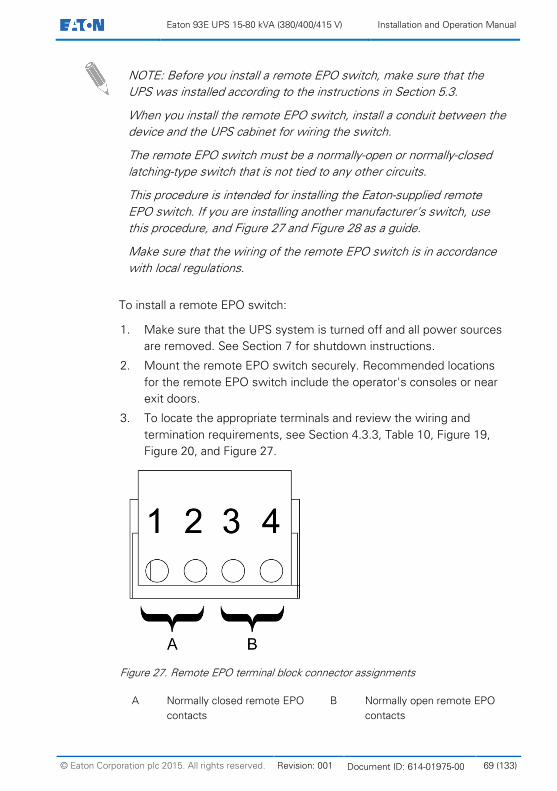
Eaton 93E UPS 15-80 kVA (380/400/415 V) Installation and Operation Manual
© Eaton Corporation plc 2015. All rights reserved. Revision: 001 Document ID: 614-01975-00 69 (133)
NOTE: Before you install a remote EPO switch, make sure that the UPS was installed according to the instructions in Section 5.3.
When you install the remote EPO switch, install a conduit between the device and the UPS cabinet for wiring the switch.
The remote EPO switch must be a normally-open or normally-closed latching-type switch that is not tied to any other circuits.
This procedure is intended for installing the Eaton-supplied remote EPO switch. If you are installing another manufacturer's switch, use this procedure, and Figure 27 and Figure 28 as a guide.
Make sure that the wiring of the remote EPO switch is in accordance with local regulations.
To install a remote EPO switch:
1. Make sure that the UPS system is turned off and all power sources are removed. See Section 7 for shutdown instructions.
2. Mount the remote EPO switch securely. Recommended locations for the remote EPO switch include the operator's consoles or near exit doors.
3. To locate the appropriate terminals and review the wiring and termination requirements, see Section 4.3.3, Table 10, Figure 19, Figure 20, and Figure 27.
Figure 27. Remote EPO terminal block connector assignments
A Normally closed remote EPO contacts
B Normally open remote EPO contacts
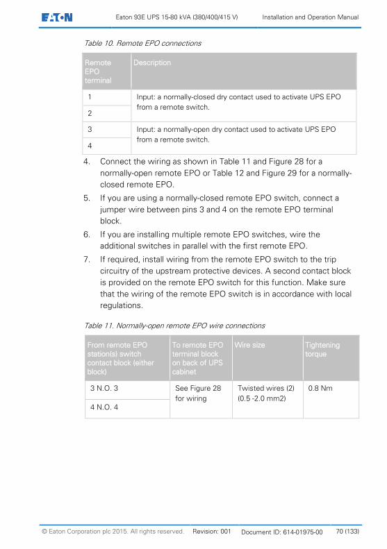
Eaton 93E UPS 15-80 kVA (380/400/415 V) Installation and Operation Manual
© Eaton Corporation plc 2015. All rights reserved. Revision: 001 Document ID: 614-01975-00 70 (133)
Table 10. Remote EPO connections
Remote EPO terminal
Description
1 Input: a normally-closed dry contact used to activate UPS EPO from a remote switch.
2
3 Input: a normally-open dry contact used to activate UPS EPO from a remote switch.
4
4. Connect the wiring as shown in Table 11 and Figure 28 for a normally-open remote EPO or Table 12 and Figure 29 for a normally-closed remote EPO.
5. If you are using a normally-closed remote EPO switch, connect a jumper wire between pins 3 and 4 on the remote EPO terminal block.
6. If you are installing multiple remote EPO switches, wire the additional switches in parallel with the first remote EPO.
7. If required, install wiring from the remote EPO switch to the trip circuitry of the upstream protective devices. A second contact block is provided on the remote EPO switch for this function. Make sure that the wiring of the remote EPO switch is in accordance with local regulations.
Table 11. Normally-open remote EPO wire connections
From remote EPO station(s) switch contact block (either block)
To remote EPO terminal block on back of UPS cabinet
Wire size Tightening torque
3 N.O. 3 See Figure 28 for wiring
Twisted wires (2) (0.5 -2.0 mm2)
0.8 Nm
4 N.O. 4
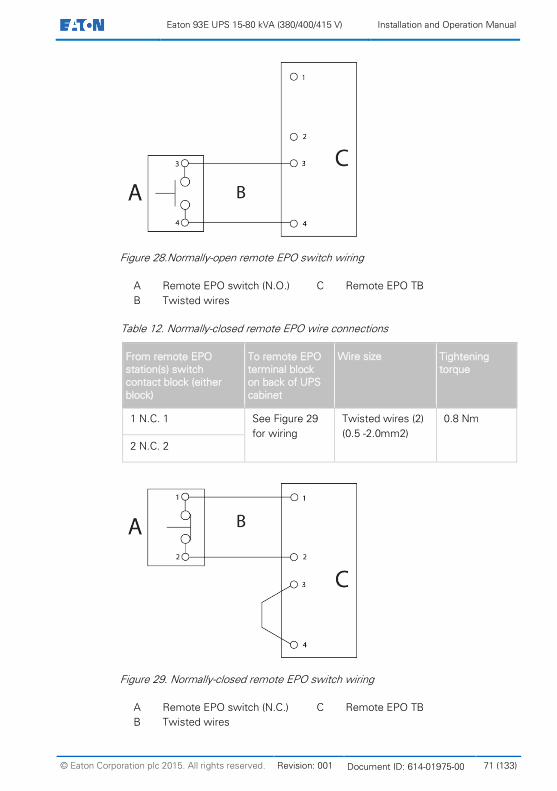
Eaton 93E UPS 15-80 kVA (380/400/415 V) Installation and Operation Manual
© Eaton Corporation plc 2015. All rights reserved. Revision: 001 Document ID: 614-01975-00 71 (133)
Figure 28.Normally-open remote EPO switch wiring
A Remote EPO switch (N.O.) C Remote EPO TB B Twisted wires
Table 12. Normally-closed remote EPO wire connections
From remote EPO station(s) switch contact block (either block)
To remote EPO terminal block on back of UPS cabinet
Wire size Tightening torque
1 N.C. 1 See Figure 29 for wiring
Twisted wires (2) (0.5 -2.0mm2)
0.8 Nm
2 N.C. 2
Figure 29. Normally-closed remote EPO switch wiring
A Remote EPO switch (N.C.) C Remote EPO TB B Twisted wires
Eaton 93E UPS 15-80 kVA (380/400/415 V) Installation and Operation Manual
© Eaton Corporation plc 2015. All rights reserved. Revision: 001 Document ID: 614-01975-00 72 (133)
5.8 Initial startup
Start-up and operational checks must be performed by a qualified service personnel authorized by Eaton. If these instructions are not followed, the warranty terms specified in Chapter 11 become void. This service is offered as a part of the sales contract for the UPS. Contact your Eaton service representative in advance to reserve a preferred startup date.
5.9 Completing the installation checklist
The final step in installing the UPS system is completing the installation checklist, see Section 4.2. This checklist ensures that you have completely installed all the hardware, cables, and other equipment. Complete all the items listed in the checklist to ensure a smooth installation. Make a copy of the installation checklist before filling it out, and retain the original.
After the installation is completed, an Eaton Customer Service Engineer must verify the operation of the UPS system and commission it to support the critical load. The service representative cannot perform any installation tasks other than verifying the software and the operating setup parameters. Service personnel may request a copy of the completed installation checklist to verify that all the applicable equipment installations have been completed.
NOTE: The installation checklist must be completed prior to starting the UPS system for the first time.
Eaton 93E UPS 15-80 kVA (380/400/415 V) Installation and Operation Manual
© Eaton Corporation plc 2015. All rights reserved. Revision: 001 Document ID: 614-01975-00 73 (133)
6 Understanding UPS operation
6.1 UPS system overview
The Eaton 93E UPS is a continuous-duty, solid-state, 3-phase, true online system that provides conditioned and uninterruptible AC power to the UPS system's output and critical load.
The basic system consists of a rectifier, battery converter, inverter, monitoring/operation control panel, integrated communication server, and digital signal processor (DSP) logic. Figure 33 and Figure 34 shows the main elements of the UPS system.
If utility power is interrupted or falls outside the parameters specified in Chapter 10, the UPS uses a backup battery supply to maintain power to the critical load for a specified period of time or until the utility power returns. For extended power outages, the UPS allows you to either transfer to an alternative power system (such as a generator) or shut down your critical load in an orderly manner.
The emergency bypass consists of a continuous duty static switch and a backfeed protection contactor. The backfeed protection contactor is located in series with the static switch. The static switch is armed and ready during normal operation.
6.2 Single UPS
A single UPS operates independently to support an applied load from the inverter, providing conditioned and uninterruptible AC power to the critical load from the output of the module. During an outage, the inverter continues to operate, supporting power to the load from the battery supply. If the unit requires service, applied loads are transferred to the internal bypass either automatically or manually. With the exception of an optional external battery cabinet, no other cabinets or equipment are required for the single UPS to successfully support its applied loads.
Eaton 93E UPS 15-80 kVA (380/400/415 V) Installation and Operation Manual
© Eaton Corporation plc 2015. All rights reserved. Revision: 001 Document ID: 614-01975-00 74 (133)
6.2.1 Modes
The Eaton 93E UPS supports a critical load in four different modes of operation:
• In the standard normal mode, the critical load is supplied by the inverter, which derives its power from rectified utility AC power. In this mode, the battery charger also provides charging current for the battery, if needed, the standard mode is the standard normal operating mode.
• In the high-efficiency (HE) mode, commercial AC power is supplied directly to the critical load through the internal bypass. If an abnormal condition is detected, the UPS transfers automatically to the standard normal mode (double-conversion on demand).
• In the bypass mode, the critical load is supported by the bypass source.
• In the battery mode, the battery provides DC power, which maintains inverter operation. The battery supports the critical load.
The following sections describe the differences in the UPS operating modes, using block diagrams to show the power flow during each mode of operation.
6.2.2 Standard normal mode
During the standard normal mode, power for the system is derived from a utility input source through the rectifier input relay. 3-phase AC input power is converted to DC using IGBT devices to produce a regulated DC voltage to the inverter. When the battery relay is closed, the battery is charged directly from the regulated rectifier output through a buck or boost DC converter, depending on the system voltage and the size of the battery string attached to the unit.
Figure 30 shows the path of electrical power through the UPS system when the UPS is operating in the normal mode.
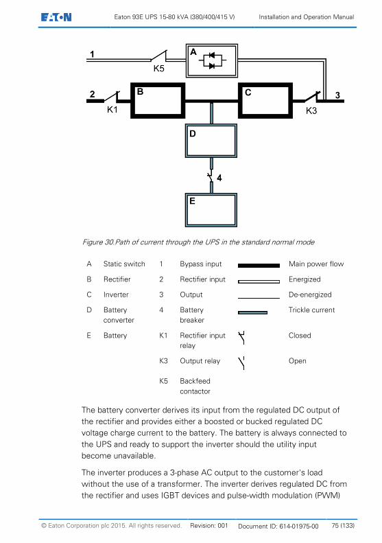
Eaton 93E UPS 15-80 kVA (380/400/415 V) Installation and Operation Manual
© Eaton Corporation plc 2015. All rights reserved. Revision: 001 Document ID: 614-01975-00 75 (133)
Figure 30.Path of current through the UPS in the standard normal mode
A Static switch 1 Bypass input Main power flow
B Rectifier 2 Rectifier input Energized
C Inverter 3 Output De-energized
D Battery converter
4 Battery breaker
Trickle current
E Battery K1 Rectifier input relay
Closed
K3 Output relay
Open
K5 Backfeed contactor
The battery converter derives its input from the regulated DC output of the rectifier and provides either a boosted or bucked regulated DC voltage charge current to the battery. The battery is always connected to the UPS and ready to support the inverter should the utility input become unavailable.
The inverter produces a 3-phase AC output to the customer's load without the use of a transformer. The inverter derives regulated DC from the rectifier and uses IGBT devices and pulse-width modulation (PWM)
Eaton 93E UPS 15-80 kVA (380/400/415 V) Installation and Operation Manual
© Eaton Corporation plc 2015. All rights reserved. Revision: 001 Document ID: 614-01975-00 76 (133)
to produce a regulated and filtered AC output. The AC output of the inverter is delivered to the system output through the output relay.
If the utility AC power is interrupted or is out of specification, the UPS automatically switches to the battery mode to support the critical load without interruption. When utility power returns, the UPS returns to the normal mode.
If the UPS becomes overloaded or unavailable, the UPS switches to the bypass mode. The UPS automatically returns to the normal mode when the overload condition is cleared and system operation is restored within the specified limits.
If the UPS suffers an internal failure, it switches automatically to the bypass mode and remains in that mode until the failure is corrected and the UPS is back in service.
6.2.3 High-efficiency mode
When the UPS is operating in the HE mode, commercial AC power is supplied directly to the critical load through the internal bypass with the power module in a standby state. If a commercial power brownout, blackout, overvoltage, undervoltage, or out-of-tolerance frequency condition occurs, the system forward-transfers to the normal mode (double-conversion on demand) or to the battery mode. When the input line returns to the normal operating range, the UPS returns to HE operation. For charging batteries in the HE mode, the UPS reverts to the normal mode to charge the batteries, and returns to the HE mode when the charge cycle is complete.
When selected, the HE mode is a normal operating mode and not an alarm condition. While the UPS is in this mode, the NORMAL light at the front display illuminates.
6.2.4 Bypass mode
CAUTION
While the UPS is in the bypass mode, the critical load is not protected from voltage or frequency fluctuations or power outages.
The UPS automatically switches to the bypass mode if it detects an overload, load fault, or internal failure. The UPS can also be transferred
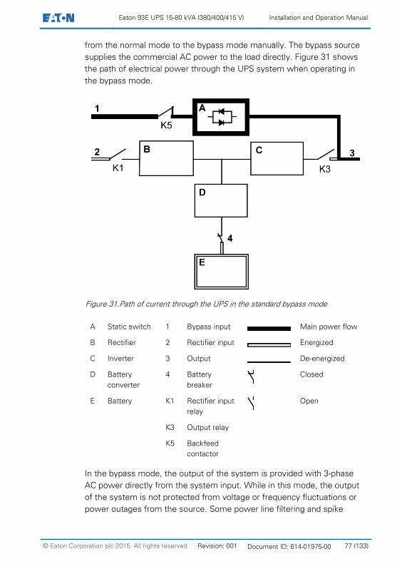
Eaton 93E UPS 15-80 kVA (380/400/415 V) Installation and Operation Manual
© Eaton Corporation plc 2015. All rights reserved. Revision: 001 Document ID: 614-01975-00 77 (133)
from the normal mode to the bypass mode manually. The bypass source supplies the commercial AC power to the load directly. Figure 31 shows the path of electrical power through the UPS system when operating in the bypass mode.
Figure 31.Path of current through the UPS in the standard bypass mode
A Static switch 1 Bypass input Main power flow
B Rectifier 2 Rectifier input Energized
C Inverter 3 Output De-energized
D Battery converter
4 Battery breaker
Closed
E Battery K1 Rectifier input relay
Open
K3 Output relay
K5 Backfeed contactor
In the bypass mode, the output of the system is provided with 3-phase AC power directly from the system input. While in this mode, the output of the system is not protected from voltage or frequency fluctuations or power outages from the source. Some power line filtering and spike
Eaton 93E UPS 15-80 kVA (380/400/415 V) Installation and Operation Manual
© Eaton Corporation plc 2015. All rights reserved. Revision: 001 Document ID: 614-01975-00 78 (133)
protection is provided to the load but no active power conditioning or battery support is available to the output of the system in the bypass mode of operation.
The internal bypass is comprised of a solid-state, silicon-controlled rectifier (SCR) continuous duty static switch, and a backfeed protection contactor. The static switch is used instantaneously anytime the inverter is unable to support the applied load. The continuous duty static switch is wired in series with the backfeed protection contactor, and together they are wired in parallel with the rectifier and inverter.
The static switch, being an electronically-controlled device, can be turned on immediately to pick up the load from the inverter while inverter output relay opens to isolate the inverter. The backfeed protection contactor (if fitted) is normally closed, ready to support the static switch unless the bypass input source becomes unavailable.
If the UPS transfers from the normal mode to the bypass mode due to any reason other than operator intervention, the UPS automatically attempts to transfer back to the normal mode (up to 3 times within a 10 minute period). The 4th transfer locks the critical load to the bypass source and requires operator intervention to transfer.
6.2.5 Battery mode
The UPS automatically transfers to the battery mode if a utility power outage occurs, or if the utility power does not conform to the specified parameters. In the battery mode, the battery provides emergency DC power which the inverter converts to AC power.
Figure 32 shows the path of electrical power through the UPS system when operating in the battery mode.
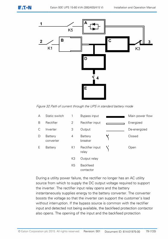
Eaton 93E UPS 15-80 kVA (380/400/415 V) Installation and Operation Manual
© Eaton Corporation plc 2015. All rights reserved. Revision: 001 Document ID: 614-01975-00 79 (133)
Figure 32.Path of current through the UPS in standard battery mode
A Static switch 1 Bypass input Main power flow
B Rectifier 2 Rectifier input Energized
C Inverter 3 Output De-energized
D Battery converter
4 Battery breaker
Closed
E Battery K1 Rectifier input relay
Open
K3 Output relay
K5 Backfeed contactor
During a utility power failure, the rectifier no longer has an AC utility source from which to supply the DC output voltage required to support the inverter. The rectifier input relay opens and the battery instantaneously supplies energy to the battery converter. The converter boosts the voltage so that the inverter can support the customer's load without interruption. If the bypass source is common with the rectifier input and detected not being available, the backfeed protection contactor also opens. The opening of the input and the backfeed protection
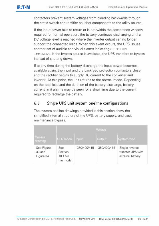
Eaton 93E UPS 15-80 kVA (380/400/415 V) Installation and Operation Manual
© Eaton Corporation plc 2015. All rights reserved. Revision: 001 Document ID: 614-01975-00 80 (133)
contactors prevent system voltages from bleeding backwards through the static switch and rectifier snubber components to the utility source.
If the input power fails to return or is not within the acceptance window required for normal operation, the battery continues discharging until a DC voltage level is reached where the inverter output can no longer support the connected loads. When this event occurs, the UPS issues another set of audible and visual alarms indicating SHUTDOWN IMMINENT. If the bypass source is available, the UPS transfers to bypass instead of shutting down.
If at any time during the battery discharge the input power becomes available again, the input and the backfeed protection contactors close and the rectifier begins to supply DC current to the converter and inverter. At this point, the unit returns to the normal mode. Depending on the total load and the duration of the battery discharge, battery current limit alarms may be seen for a short time due to the current required to recharge the battery.
6.3 Single UPS unit system oneline configurations
The system oneline drawings provided in this section show the simplified internal structure of the UPS, battery supply, and basic maintenance bypass.
Voltage
Oneline drawing
UPS model Input Output System type
See Figure 33 and Figure 34
See Section 10.1 for the model
380/400/415 380/400/415 Single reverse transfer UPS with external battery
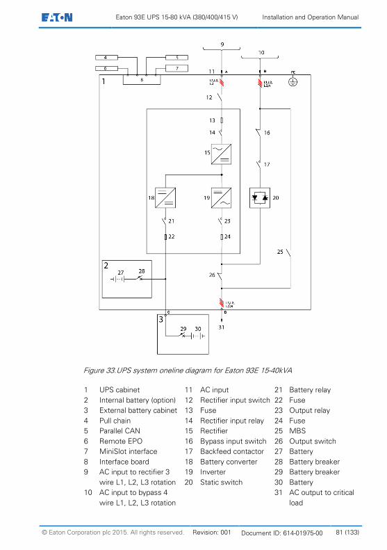
Eaton 93E UPS 15-80 kVA (380/400/415 V) Installation and Operation Manual
© Eaton Corporation plc 2015. All rights reserved. Revision: 001 Document ID: 614-01975-00 81 (133)
Figure 33.UPS system oneline diagram for Eaton 93E 15-40kVA
1 UPS cabinet 11 AC input 21 Battery relay 2 Internal battery (option) 12 Rectifier input switch 22 Fuse 3 External battery cabinet 13 Fuse 23 Output relay 4 Pull chain 14 Rectifier input relay 24 Fuse 5 Parallel CAN 15 Rectifier 25 MBS 6 Remote EPO 16 Bypass input switch 26 Output switch 7 MiniSlot interface 17 Backfeed contactor 27 Battery 8 Interface board 18 Battery converter 28 Battery breaker 9 AC input to rectifier 3
wire L1, L2, L3 rotation 19 Inverter 29 Battery breaker 20 Static switch 30 Battery
10 AC input to bypass 4 wire L1, L2, L3 rotation
31 AC output to critical load
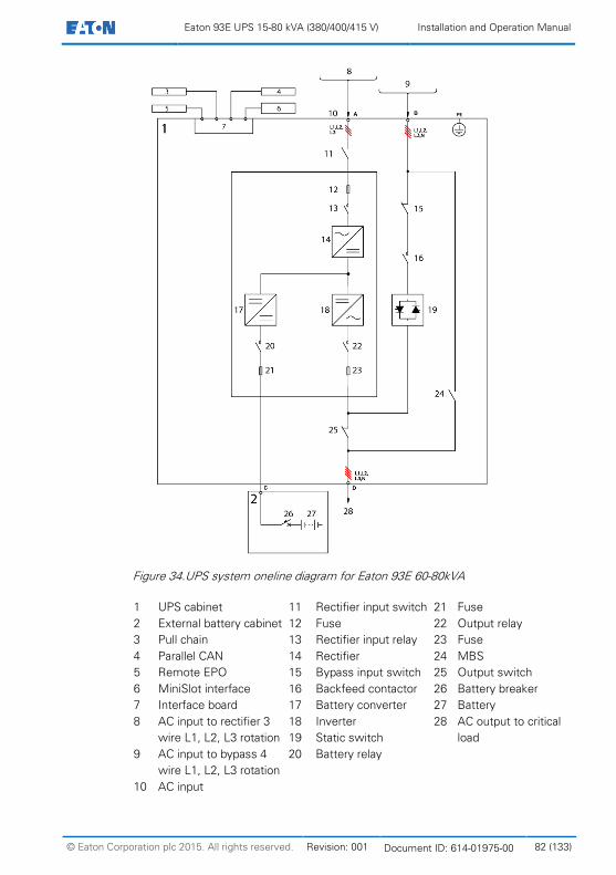
Eaton 93E UPS 15-80 kVA (380/400/415 V) Installation and Operation Manual
© Eaton Corporation plc 2015. All rights reserved. Revision: 001 Document ID: 614-01975-00 82 (133)
Figure 34.UPS system oneline diagram for Eaton 93E 60-80kVA
1 UPS cabinet 11 Rectifier input switch 21 Fuse 2 External battery cabinet 12 Fuse 22 Output relay 3 Pull chain 13 Rectifier input relay 23 Fuse 4 Parallel CAN 14 Rectifier 24 MBS 5 Remote EPO 15 Bypass input switch 25 Output switch 6 MiniSlot interface 16 Backfeed contactor 26 Battery breaker 7 Interface board 17 Battery converter 27 Battery 8 AC input to rectifier 3
wire L1, L2, L3 rotation 18 Inverter 28 AC output to critical
load 19 Static switch 9 AC input to bypass 4
wire L1, L2, L3 rotation 20 Battery relay
10 AC input
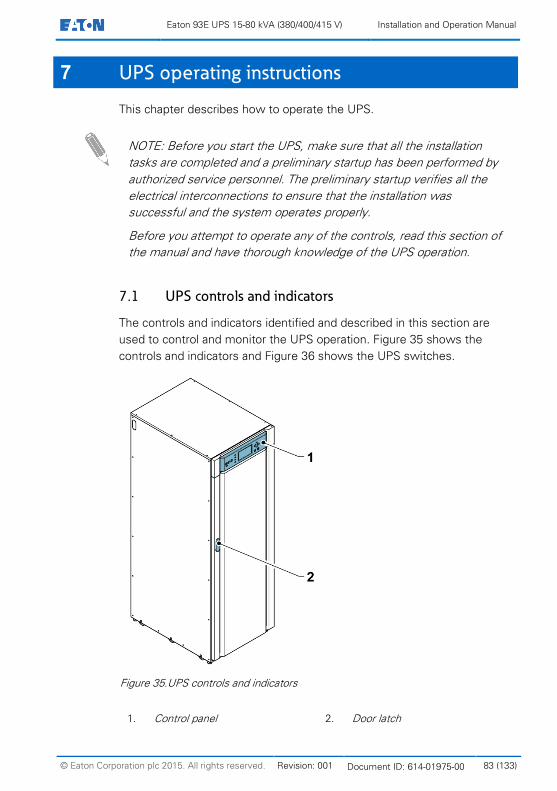
Eaton 93E UPS 15-80 kVA (380/400/415 V) Installation and Operation Manual
© Eaton Corporation plc 2015. All rights reserved. Revision: 001 Document ID: 614-01975-00 83 (133)
7 UPS operating instructions
This chapter describes how to operate the UPS.
NOTE: Before you start the UPS, make sure that all the installation tasks are completed and a preliminary startup has been performed by authorized service personnel. The preliminary startup verifies all the electrical interconnections to ensure that the installation was successful and the system operates properly.
Before you attempt to operate any of the controls, read this section of the manual and have thorough knowledge of the UPS operation.
7.1 UPS controls and indicators
The controls and indicators identified and described in this section are used to control and monitor the UPS operation. Figure 35 shows the controls and indicators and Figure 36 shows the UPS switches.
Figure 35.UPS controls and indicators
1. Control panel 2. Door latch
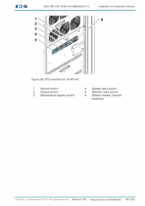
Eaton 93E UPS 15-80 kVA (380/400/415 V) Installation and Operation Manual
© Eaton Corporation plc 2015. All rights reserved. Revision: 001 Document ID: 614-01975-00 84 (133)
Figure 36.UPS switches for 15-40 kVA
1. Neutral switch 2. Output switch 3. Maintenance bypass switch
4. Bypass input switch 5. Rectifier input switch 6. Battery breaker (internal
batteries)
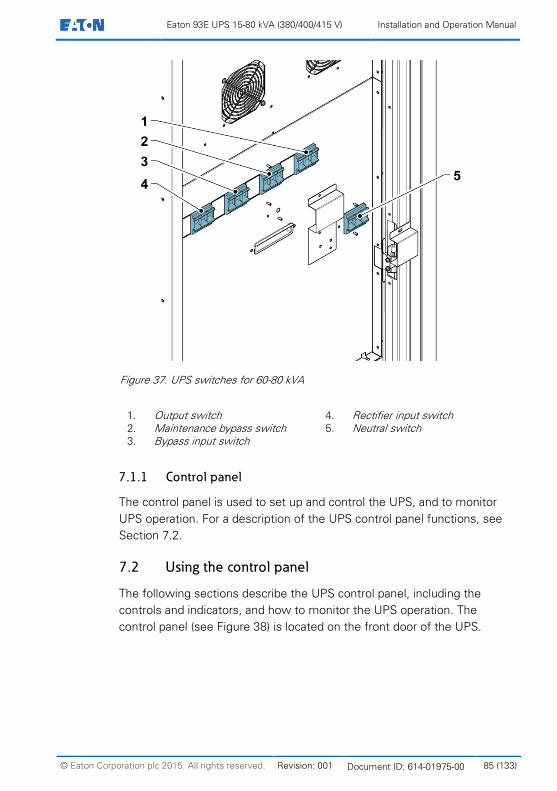
Eaton 93E UPS 15-80 kVA (380/400/415 V) Installation and Operation Manual
© Eaton Corporation plc 2015. All rights reserved. Revision: 001 Document ID: 614-01975-00 85 (133)
Figure 37. UPS switches for 60-80 kVA
1. Output switch 2. Maintenance bypass switch 3. Bypass input switch
4. Rectifier input switch 5. Neutral switch
7.1.1 Control panel
The control panel is used to set up and control the UPS, and to monitor UPS operation. For a description of the UPS control panel functions, see Section 7.2.
7.2 Using the control panel
The following sections describe the UPS control panel, including the controls and indicators, and how to monitor the UPS operation. The control panel (see Figure 38) is located on the front door of the UPS.
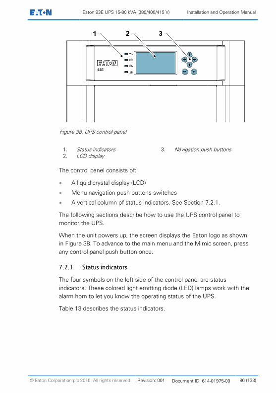
Eaton 93E UPS 15-80 kVA (380/400/415 V) Installation and Operation Manual
© Eaton Corporation plc 2015. All rights reserved. Revision: 001 Document ID: 614-01975-00 86 (133)
Figure 38. UPS control panel
1. Status indicators 2. LCD display
3. Navigation push buttons
The control panel consists of:
• A liquid crystal display (LCD)
• Menu navigation push buttons switches
• A vertical column of status indicators. See Section 7.2.1.
The following sections describe how to use the UPS control panel to monitor the UPS.
When the unit powers up, the screen displays the Eaton logo as shown in Figure 38. To advance to the main menu and the Mimic screen, press any control panel push button once.
7.2.1 Status indicators
The four symbols on the left side of the control panel are status indicators. These colored light emitting diode (LED) lamps work with the alarm horn to let you know the operating status of the UPS.
Table 13 describes the status indicators.
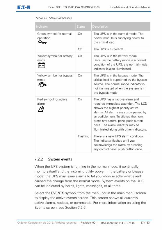
Eaton 93E UPS 15-80 kVA (380/400/415 V) Installation and Operation Manual
© Eaton Corporation plc 2015. All rights reserved. Revision: 001 Document ID: 614-01975-00 87 (133)
Table 13. Status indicators
Indicator Status Description
Green symbol for normal operation
On The UPS is in the normal mode. The power module is supplying power to the critical load.
Off The UPS is turned off.
Yellow symbol for battery mode
On The UPS is in the battery mode. Because the battery mode is a normal condition of the UPS, the normal mode indicator is also illuminated.
Yellow symbol for bypass mode
On The UPS is in the bypass mode. The critical load is supported by the bypass source. The normal mode indicator is not illuminated when the system is in the bypass mode.
Red symbol for active alarm
On The UPS has an active alarm and requires immediate attention. The LCD shows the highest priority active alarms. All alarms are accompanied by an audible horn. To silence the horn, press any control panel push button once. The alarm indicator may be illuminated along with other indicators.
Flashing There is a new UPS alarm condition. The indicator flashes until you acknowledge the alarm by pressing any control panel push button once.
7.2.2 System events
When the UPS system is running in the normal mode, it continually monitors itself and the incoming utility power. In the battery or bypass mode, the UPS may issue alarms to let you know exactly what event caused the change from the normal mode. System events on the UPS can be indicated by horns, lights, messages, or all three.
Select the EVENTS symbol from the menu bar in the main menu screen to display the active events screen. This screen shows all currently active alarms, notices, or commands. For more information on using the Events screen, see Section 7.2.6.
Eaton 93E UPS 15-80 kVA (380/400/415 V) Installation and Operation Manual
© Eaton Corporation plc 2015. All rights reserved. Revision: 001 Document ID: 614-01975-00 88 (133)
• System event horns
The system event horn beeps to alert the operator that an event that requires attention is taking place. The horn cycles at a half-second rate.
• System event indicators
The status indicators on the UPS control panel work with the event horn to let the operator know when the UPS is operating in any mode other than normal. Only the normal mode indicator is illuminated during normal UPS system operation. The other indicators illuminate to indicate alarms or events. When an alarm occurs, first check these indicators to see what type of event has taken place. For descriptions of the status indicators, see Section 7.2.1.
• System event messages
When a system event occurs, a message appears on the LCD in the UPS status area. This message is also written to the Events Log and may be added to the History Log. The messages are divided into four categories: alarms, notices, status, and commands.
7.2.3 Using the LCD and push buttons
The LCD on the control panel provides an operator interface with the UPS system. Figure 39 identifies the display areas discussed in the following sections.
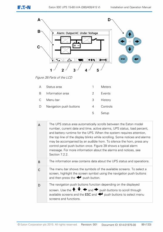
Eaton 93E UPS 15-80 kVA (380/400/415 V) Installation and Operation Manual
© Eaton Corporation plc 2015. All rights reserved. Revision: 001 Document ID: 614-01975-00 89 (133)
Figure 39.Parts of the LCD
A Status area 1 Meters
B Information area 2 Events
C Menu bar 3 History
D Navigation push buttons 4 Controls
5 Setup
A The UPS status area automatically scrolls between the Eaton model number, current date and time, active alarms, UPS status, load percent, and battery runtime for the UPS. When the system requires attention, the top line of the display blinks while scrolling. Some notices and alarms may be accompanied by an audible horn. To silence the horn, press any control panel push button once. Figure 39 shows a typical alarm message. For more information about the alarms and notices, see Section 7.2.2.
B The information area contains data about the UPS status and operations.
C The menu bar shows the symbols of the available screens. To select a screen, highlight the screen symbol using the navigation push buttons and then press the push button.
D The navigation push buttons function depending on the displayed
screen. Use the , , and push buttons to scroll through available screens and the ESC and push buttons to select menu screens and functions.
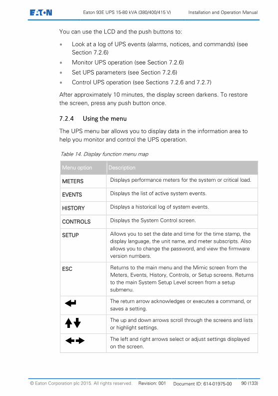
Eaton 93E UPS 15-80 kVA (380/400/415 V) Installation and Operation Manual
© Eaton Corporation plc 2015. All rights reserved. Revision: 001 Document ID: 614-01975-00 90 (133)
You can use the LCD and the push buttons to:
• Look at a log of UPS events (alarms, notices, and commands) (see Section 7.2.6)
• Monitor UPS operation (see Section 7.2.6)
• Set UPS parameters (see Section 7.2.6)
• Control UPS operation (see Sections 7.2.6 and 7.2.7)
After approximately 10 minutes, the display screen darkens. To restore the screen, press any push button once.
7.2.4 Using the menu
The UPS menu bar allows you to display data in the information area to help you monitor and control the UPS operation.
Table 14. Display function menu map
Menu option Description
METERS Displays performance meters for the system or critical load.
EVENTS Displays the list of active system events.
HISTORY Displays a historical log of system events.
CONTROLS Displays the System Control screen.
SETUP Allows you to set the date and time for the time stamp, the display language, the unit name, and meter subscripts. Also allows you to change the password, and view the firmware version numbers.
ESC Returns to the main menu and the Mimic screen from the Meters, Events, History, Controls, or Setup screens. Returns to the main System Setup Level screen from a setup submenu.
The return arrow acknowledges or executes a command, or saves a setting.
The up and down arrows scroll through the screens and lists or highlight settings.
The left and right arrows select or adjust settings displayed on the screen.
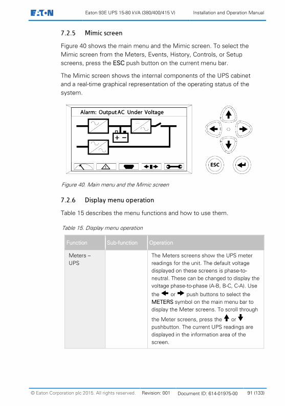
Eaton 93E UPS 15-80 kVA (380/400/415 V) Installation and Operation Manual
© Eaton Corporation plc 2015. All rights reserved. Revision: 001 Document ID: 614-01975-00 91 (133)
7.2.5 Mimic screen
Figure 40 shows the main menu and the Mimic screen. To select the Mimic screen from the Meters, Events, History, Controls, or Setup screens, press the ESC push button on the current menu bar.
The Mimic screen shows the internal components of the UPS cabinet and a real-time graphical representation of the operating status of the system.
Figure 40. Main menu and the Mimic screen
7.2.6 Display menu operation
Table 15 describes the menu functions and how to use them.
Table 15. Display menu operation
Function Sub-function Operation
Meters – UPS
The Meters screens show the UPS meter readings for the unit. The default voltage displayed on these screens is phase-to-neutral. These can be changed to display the voltage phase-to-phase (A-B, B-C, C-A). Use
the or push buttons to select the METERS symbol on the main menu bar to display the Meter screens. To scroll through
the Meter screens, press the or pushbutton. The current UPS readings are displayed in the information area of the screen.
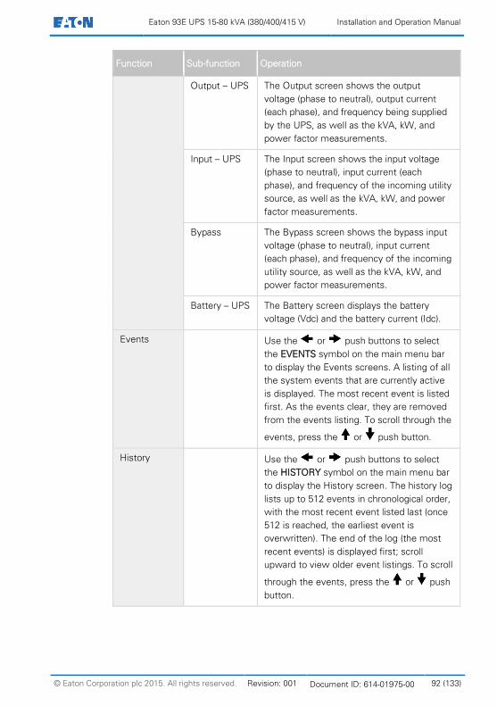
Eaton 93E UPS 15-80 kVA (380/400/415 V) Installation and Operation Manual
© Eaton Corporation plc 2015. All rights reserved. Revision: 001 Document ID: 614-01975-00 92 (133)
Function Sub-function Operation
Output – UPS The Output screen shows the output voltage (phase to neutral), output current (each phase), and frequency being supplied by the UPS, as well as the kVA, kW, and power factor measurements.
Input – UPS The Input screen shows the input voltage (phase to neutral), input current (each phase), and frequency of the incoming utility source, as well as the kVA, kW, and power factor measurements.
Bypass The Bypass screen shows the bypass input voltage (phase to neutral), input current (each phase), and frequency of the incoming utility source, as well as the kVA, kW, and power factor measurements.
Battery – UPS The Battery screen displays the battery voltage (Vdc) and the battery current (Idc).
Events Use the or push buttons to select the EVENTS symbol on the main menu bar to display the Events screens. A listing of all the system events that are currently active is displayed. The most recent event is listed first. As the events clear, they are removed from the events listing. To scroll through the
events, press the or push button.
History Use the or push buttons to select the HISTORY symbol on the main menu bar to display the History screen. The history log lists up to 512 events in chronological order, with the most recent event listed last (once 512 is reached, the earliest event is overwritten). The end of the log (the most recent events) is displayed first; scroll upward to view older event listings. To scroll
through the events, press the or push button.
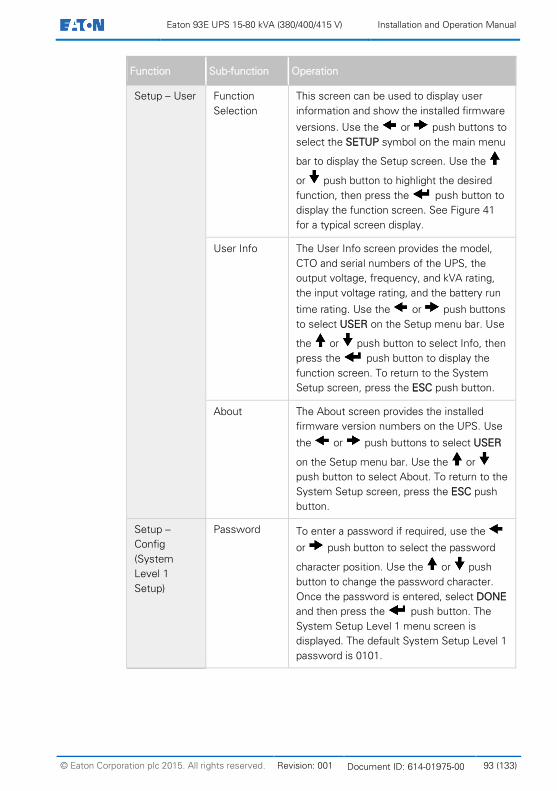
Eaton 93E UPS 15-80 kVA (380/400/415 V) Installation and Operation Manual
© Eaton Corporation plc 2015. All rights reserved. Revision: 001 Document ID: 614-01975-00 93 (133)
Function Sub-function Operation
Setup – User Function Selection
This screen can be used to display user information and show the installed firmware
versions. Use the or push buttons to select the SETUP symbol on the main menu
bar to display the Setup screen. Use the
or push button to highlight the desired function, then press the push button to display the function screen. See Figure 41 for a typical screen display.
User Info The User Info screen provides the model, CTO and serial numbers of the UPS, the output voltage, frequency, and kVA rating, the input voltage rating, and the battery run
time rating. Use the or push buttons to select USER on the Setup menu bar. Use
the or push button to select Info, then press the push button to display the function screen. To return to the System Setup screen, press the ESC push button.
About The About screen provides the installed firmware version numbers on the UPS. Use
the or push buttons to select USER
on the Setup menu bar. Use the or push button to select About. To return to the System Setup screen, press the ESC push button.
Setup – Config (System Level 1 Setup)
Password To enter a password if required, use the
or push button to select the password
character position. Use the or push button to change the password character. Once the password is entered, select DONE and then press the push button. The System Setup Level 1 menu screen is displayed. The default System Setup Level 1 password is 0101.
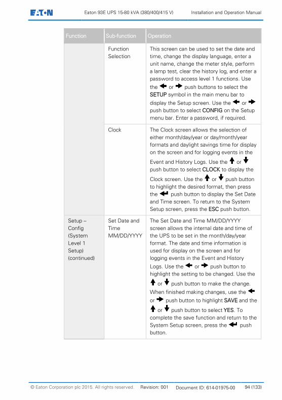
Eaton 93E UPS 15-80 kVA (380/400/415 V) Installation and Operation Manual
© Eaton Corporation plc 2015. All rights reserved. Revision: 001 Document ID: 614-01975-00 94 (133)
Function Sub-function Operation
Function Selection
This screen can be used to set the date and time, change the display language, enter a unit name, change the meter style, perform a lamp test, clear the history log, and enter a password to access level 1 functions. Use
the or push buttons to select the SETUP symbol in the main menu bar to
display the Setup screen. Use the or push button to select CONFIG on the Setup menu bar. Enter a password, if required.
Clock The Clock screen allows the selection of either month/day/year or day/month/year formats and daylight savings time for display on the screen and for logging events in the
Event and History Logs. Use the or push button to select CLOCK to display the
Clock screen. Use the or push button to highlight the desired format, then press the push button to display the Set Date and Time screen. To return to the System Setup screen, press the ESC push button.
Setup – Config (System Level 1 Setup) (continued)
Set Date and Time MM/DD/YYYY
The Set Date and Time MM/DD/YYYY screen allows the internal date and time of the UPS to be set in the month/day/year format. The date and time information is used for display on the screen and for logging events in the Event and History
Logs. Use the or push button to highlight the setting to be changed. Use the
or push button to make the change.
When finished making changes, use the
or push button to highlight SAVE and the
or push button to select YES. To complete the save function and return to the System Setup screen, press the push button.

Eaton 93E UPS 15-80 kVA (380/400/415 V) Installation and Operation Manual
© Eaton Corporation plc 2015. All rights reserved. Revision: 001 Document ID: 614-01975-00 95 (133)
Function Sub-function Operation
Set Date and Time DD/MM/YYYY
The Set Date and Time DD/MM/YYYY screen allows the internal date and time of the UPS to be set in the day/month/year format. The date and time information is used for display on the screen and for logging events in the Event and History
Logs. Use the or push button to highlight the setting to be changed. Use the
or push button to make the change.
When finished making changes, use the
or push button to highlight SAVE and the
or push button to select YES. To complete the save function and return to the System Setup screen, press the push button.
Language The Language Setup screen allows you to select the display menu language. Use the
or push button to highlight Language, then press the push button to display
the Language screen. Use the or push button to highlight the desired language, then press the push button. To return to the System Setup screen, press the ESC pushbutton.
Unit Name The Unit Name Setup screen allows you to
enter a unit name. Use the or push button to highlight Unit Name, then press the push button to display the Unit
Name screen. Use the or push button to highlight the character to be
changed. Use the or push button to make the change. When finished making
changes, use the or push button to
highlight SAVE and the or push button to select YES. To complete the save function and return to the System Setup screen, press the push button. To return to the System Setup screen, press the ESC push button.
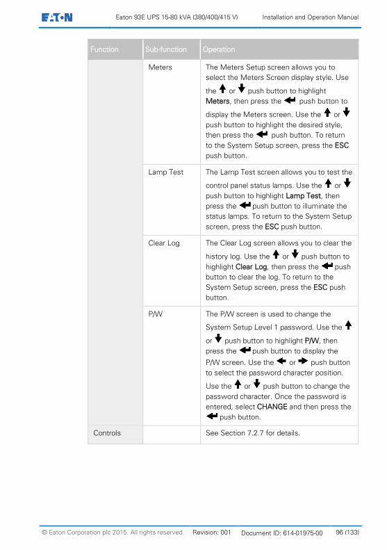
Eaton 93E UPS 15-80 kVA (380/400/415 V) Installation and Operation Manual
© Eaton Corporation plc 2015. All rights reserved. Revision: 001 Document ID: 614-01975-00 96 (133)
Function Sub-function Operation
Meters The Meters Setup screen allows you to select the Meters Screen display style. Use
the or push button to highlight Meters, then press the push button to
display the Meters screen. Use the or push button to highlight the desired style, then press the push button. To return to the System Setup screen, press the ESC push button.
Lamp Test The Lamp Test screen allows you to test the
control panel status lamps. Use the or push button to highlight Lamp Test, then press the push button to illuminate the status lamps. To return to the System Setup screen, press the ESC push button.
Clear Log The Clear Log screen allows you to clear the
history log. Use the or push button to highlight Clear Log, then press the push button to clear the log. To return to the System Setup screen, press the ESC push button.
P/W The P/W screen is used to change the
System Setup Level 1 password. Use the
or push button to highlight P/W, then press the push button to display the
P/W screen. Use the or push button to select the password character position.
Use the or push button to change the password character. Once the password is entered, select CHANGE and then press the
push button.
Controls See Section 7.2.7 for details.
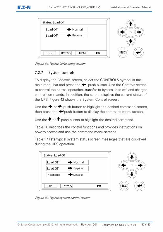
Eaton 93E UPS 15-80 kVA (380/400/415 V) Installation and Operation Manual
© Eaton Corporation plc 2015. All rights reserved. Revision: 001 Document ID: 614-01975-00 97 (133)
Figure 41.Typical initial setup screen
7.2.7 System controls
To display the Controls screen, select the CONTROLS symbol in the main menu bar and press the push button. Use the Controls screen to control the normal operation, transfer to bypass, load off, and charger control commands. In addition, the screen displays the current status of the UPS. Figure 42 shows the System Control screen.
Use the or push button to highlight the desired command screen, then press the push button to display the command menu screen.
Use the or push button to highlight the desired command.
Table 16 describes the control functions and provides instructions on how to access and use the command menu screens.
Table 17 lists typical system status screen messages that are displayed during the UPS operation.
Figure 42.Typical system control screen
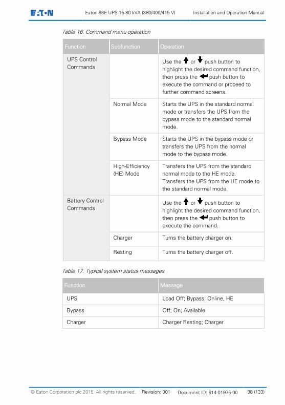
Eaton 93E UPS 15-80 kVA (380/400/415 V) Installation and Operation Manual
© Eaton Corporation plc 2015. All rights reserved. Revision: 001 Document ID: 614-01975-00 98 (133)
Table 16. Command menu operation
Function Subfunction Operation
UPS Control Commands
Use the or push button to highlight the desired command function, then press the push button to execute the command or proceed to further command screens.
Normal Mode Starts the UPS in the standard normal mode or transfers the UPS from the bypass mode to the standard normal mode.
Bypass Mode Starts the UPS in the bypass mode or transfers the UPS from the normal mode to the bypass mode.
High-Efficiency (HE) Mode
Transfers the UPS from the standard normal mode to the HE mode. Transfers the UPS from the HE mode to the standard normal mode.
Battery Control Commands
Use the or push button to highlight the desired command function, then press the push button to execute the command.
Charger Turns the battery charger on.
Resting Turns the battery charger off.
Table 17. Typical system status messages
Function Message
UPS Load Off; Bypass; Online, HE
Bypass Off; On; Available
Charger Charger Resting; Charger
Eaton 93E UPS 15-80 kVA (380/400/415 V) Installation and Operation Manual
© Eaton Corporation plc 2015. All rights reserved. Revision: 001 Document ID: 614-01975-00 99 (133)
7.3 Single UPS operation
NOTE: Note switch operation nomenclature:
Open = O = Off
Closed = I = On.
Refer to the External Battery Cabinet Installation Manual for the EBC battery breaker location.
7.3.1 Starting the UPS in the bypass mode
If the inverter output of the UPS is not available and the critical load needs to be energized, start the UPS in the bypass mode.
CAUTION
In the bypass mode, the critical load is not protected from commercial power anomalies.
To start the UPS system:
1. To unfasten the front door, lift the latch from the bottom, turn it to the right (counter-clockwise) and swing the door open (see Figure 35).
2. Make sure that the bypass switch is open and the neutral switch is closed.
3. Close the UPS input feeder circuit breaker.
4. If the UPSs are wired for dual input, close the UPS bypass input feeder circuit breaker.
5. Make sure that the rectifier input switch is closed.
6. Make sure that the bypass input switch is closed.
7. Make sure that the output switch is closed.
8. Make sure that the MBS cover is installed.
9. Close the door and secure the latch.
10. Close the external battery breakers.
11. Wait until the UPS control panel display becomes active and indicates logic power.
12. Check that there are no alarms active.
Eaton 93E UPS 15-80 kVA (380/400/415 V) Installation and Operation Manual
© Eaton Corporation plc 2015. All rights reserved. Revision: 001 Document ID: 614-01975-00 100 (133)
13. Select the CONTROLS symbol in the main menu bar.
The System Control screen is displayed.
14. If not already selected, select UPS in the System Control screen.
15. In the UPS System Control screen, select the LOAD OFF → BYPASS command and press the push button.
7.3.2 Starting the UPS in the standard normal mode (default mode)
To start the UPS system:
1. To unfasten the front door, lift the latch from the bottom, turn it to the right (counter-clockwise) and swing the door open (see Figure 35).
2. Make sure that the maintenance bypass switch is open and the neutral switch is closed.
3. Close the UPS input feeder circuit breaker.
4. If the UPSs are wired for dual input, close the UPS bypass input feeder circuit breaker.
5. Make sure that the rectifier input switch is closed.
6. Make sure that the bypass input switch is closed.
7. Make sure that the output switch is closed.
8. Make sure that the MBS cover is installed.
9. Close the door and secure the latch.
10. Close the internal and external battery breakers.
11. Wait until the UPS control panel display becomes active and indicates logic power.
12. Check that there are no alarms active.
13. Select the CONTROLS symbol in the main menu bar.
The System Control screen is displayed.
14. If not already selected, select UPS in the System Control screen.
15. In the UPS System Control screen, select the LOAD OFF → NORMAL command and press the push button.
Eaton 93E UPS 15-80 kVA (380/400/415 V) Installation and Operation Manual
© Eaton Corporation plc 2015. All rights reserved. Revision: 001 Document ID: 614-01975-00 101 (133)
16. If requested, enter the Level 1 password. Default password is 1111.
After you have entered the password, UPS transfers first to bypass and the bypass LED is illuminated.
The DC-link and the rectifier is turned on. The rectifier input relay closes while the DC-link continues to ramp up to full voltage. After this, the inverter is turned on and the UPS output relay closes and the static switch turns off. Power is now supplied to the critical load in the standard normal mode. It takes approximately one minute for the UPS to achieve the standard normal mode.
The normal mode status indicator is illuminated.
7.3.3 Transfer from the bypass mode to the normal mode
To transfer the critical load to the normal mode:
1. Select the CONTROLS symbol in the main menu bar.
The System Control screen is displayed.
2. If not already selected, select UPS in the System Control screen.
3. In the UPS System Control screen, select the BYPASS → NORMAL command and press the push button.
The UPS transfers to the normal mode. If the power module is not available, the system remains on bypass and an alarm sounds.
The normal mode status indicator is illuminated.
7.3.4 Transfer from the normal mode to the bypass mode
To transfer the critical load to the bypass mode:
CAUTION
In the bypass mode, the critical load is not protected from commercial power anomalies.
1. Select the CONTROLS symbol in the main menu bar.
The System Control screen is displayed.
2. If not already selected, select UPS in the System Control screen.
3. In the UPS System Control screen, select the NORMAL → BYPASS command and press the push button.
The UPS transfers to the bypass mode.
Eaton 93E UPS 15-80 kVA (380/400/415 V) Installation and Operation Manual
© Eaton Corporation plc 2015. All rights reserved. Revision: 001 Document ID: 614-01975-00 102 (133)
The bypass status indicator is illuminated. The power module remains on.
WARNING
Power is present inside the UPS cabinet.
7.3.5 Transfer from the standard normal mode to the HE mode
To transfer the load to the HE mode:
1. Select the CONTROLS symbol in the main menu bar.
The System Control screen is displayed.
2. If not already selected, select UPS in the System Control screen.
3. In the UPS System Control screen, select the HE: DISABLE → ENABLE command and press the push button.
After the battery is fully charged, the UPS transfers to the HE mode if no abnormal power conditions are detected.
If abnormal power conditions are detected, the UPS waits and transfers to the HE mode when the conditions are cleared.
The normal mode status indicator is illuminated.
7.3.6 Transfer from the HE mode to the standard normal mode
To transfer the load to the standard normal mode:
1. Select the CONTROLS symbol in the main menu bar.
The System Control screen is displayed.
2. If not already selected, select UPS in the System Control screen.
3. In the UPS System Control screen, select the HE: ENABLE → DISABLE command and press the push button.
The UPS transfers to the standard normal mode.
The normal mode status indicator is illuminated.
Eaton 93E UPS 15-80 kVA (380/400/415 V) Installation and Operation Manual
© Eaton Corporation plc 2015. All rights reserved. Revision: 001 Document ID: 614-01975-00 103 (133)
7.3.7 Transfer from the normal mode to internal maintenance bypass
WARNING
Do not use the internal Maintenance Bypass Switch (MBS) in UPSes that are installed as a parallel system.
To transfer the load to maintenance bypass:
1. In the UPS System Control screen, select the NORMAL → BYPASS command and press the push button.
2. Loosen the screws that fix the cover over the maintenance bypass switch.
This action signals the UPS to transfer to static bypass (if the UPS is not already on static bypass). See Figure 36 for the switch arrangement.
3. Check that that the LCD/LED display indicates that the UPS is in the bypass mode.
4. Close the maintenance bypass switch.
5. Open the bypass input and output switches separately.
6. Loosen the screws that fix the cover over the neutral switch (60-80 kVA) and open the neutral switch.
. DANGER
Only service technicians are allowed to operate the neutral switch. Otherwise, keep the neutral switch closed.
Only authorized Eaton Customer Service Engineers are allowed to perform the maintenance bypass operation.
WARNING
Power is present inside the UPS cabinet.
Eaton 93E UPS 15-80 kVA (380/400/415 V) Installation and Operation Manual
© Eaton Corporation plc 2015. All rights reserved. Revision: 001 Document ID: 614-01975-00 104 (133)
7.3.8 Transfer from internal maintenance bypass to the normal mode
To transfer the load to the normal mode:
1. Close the neutral switch, slide the cover plate over the neutral switch and tighten the screws.
2. Close the rectifier input and bypass input switches.
3. Use the control panel to command the UPS to run in the bypass mode.
4. Check that the LCD/LED display indicates that the UPS is in the bypass mode.
5. Close the output switch.
6. Open the maintenance bypass switch, slide the cover plate to the left and tighten the screws.
7. Use the control panel to command the UPS to transfer to the normal mode.
7.3.9 UPS and critical load shutdown
To perform maintenance or service on the critical load, shut down the power to the load:
1. Turn off all the equipment that is being powered by the UPS.
2. Perform the LOAD OFF procedure as instructed in Section 7.3.12.
The output and bypass backfeed relay (if fitted) open, and the power module is turned off.
3. In the UPS System Control screen, select the STANDBY → SHUTDOWN command and press the push button.
The input and battery relay open.
WARNING
Power is present inside the UPS cabinet after the upstream input feeder circuit breakers are opened because of the installed external battery cabinet.
4. Open the UPS input switch.
5. Open the bypass input switch.
6. Make sure that the maintenance bypass switch is open.
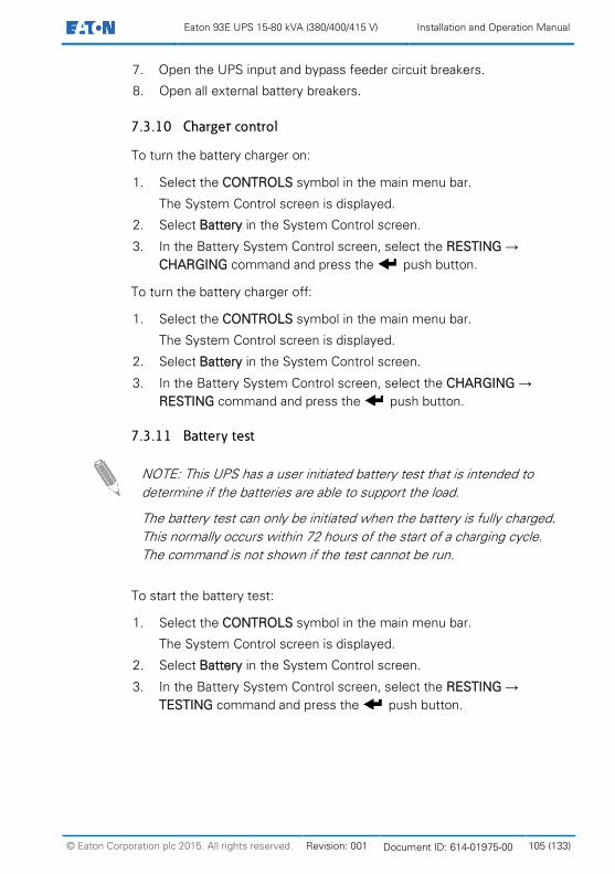
Eaton 93E UPS 15-80 kVA (380/400/415 V) Installation and Operation Manual
© Eaton Corporation plc 2015. All rights reserved. Revision: 001 Document ID: 614-01975-00 105 (133)
7. Open the UPS input and bypass feeder circuit breakers.
8. Open all external battery breakers.
7.3.10 Charger control
To turn the battery charger on:
1. Select the CONTROLS symbol in the main menu bar.
The System Control screen is displayed.
2. Select Battery in the System Control screen.
3. In the Battery System Control screen, select the RESTING → CHARGING command and press the push button.
To turn the battery charger off:
1. Select the CONTROLS symbol in the main menu bar.
The System Control screen is displayed.
2. Select Battery in the System Control screen.
3. In the Battery System Control screen, select the CHARGING → RESTING command and press the push button.
7.3.11 Battery test
NOTE: This UPS has a user initiated battery test that is intended to determine if the batteries are able to support the load.
The battery test can only be initiated when the battery is fully charged. This normally occurs within 72 hours of the start of a charging cycle. The command is not shown if the test cannot be run.
To start the battery test:
1. Select the CONTROLS symbol in the main menu bar.
The System Control screen is displayed.
2. Select Battery in the System Control screen.
3. In the Battery System Control screen, select the RESTING → TESTING command and press the push button.
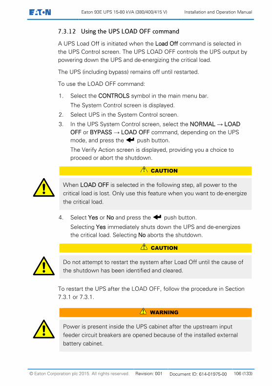
Eaton 93E UPS 15-80 kVA (380/400/415 V) Installation and Operation Manual
© Eaton Corporation plc 2015. All rights reserved. Revision: 001 Document ID: 614-01975-00 106 (133)
7.3.12 Using the UPS LOAD OFF command
A UPS Load Off is initiated when the Load Off command is selected in the UPS Control screen. The UPS LOAD OFF controls the UPS output by powering down the UPS and de-energizing the critical load.
The UPS (including bypass) remains off until restarted.
To use the LOAD OFF command:
1. Select the CONTROLS symbol in the main menu bar.
The System Control screen is displayed.
2. Select UPS in the System Control screen.
3. In the UPS System Control screen, select the NORMAL → LOAD OFF or BYPASS → LOAD OFF command, depending on the UPS mode, and press the push button.
The Verify Action screen is displayed, providing you a choice to proceed or abort the shutdown.
CAUTION
When LOAD OFF is selected in the following step, all power to the critical load is lost. Only use this feature when you want to de-energize the critical load.
4. Select Yes or No and press the push button.
Selecting Yes immediately shuts down the UPS and de-energizes the critical load. Selecting No aborts the shutdown.
CAUTION
Do not attempt to restart the system after Load Off until the cause of the shutdown has been identified and cleared.
To restart the UPS after the LOAD OFF, follow the procedure in Section 7.3.1 or 7.3.1.
WARNING
Power is present inside the UPS cabinet after the upstream input feeder circuit breakers are opened because of the installed external battery cabinet.
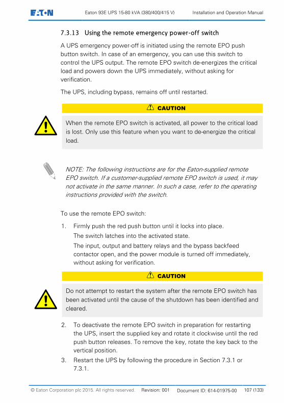
Eaton 93E UPS 15-80 kVA (380/400/415 V) Installation and Operation Manual
© Eaton Corporation plc 2015. All rights reserved. Revision: 001 Document ID: 614-01975-00 107 (133)
7.3.13 Using the remote emergency power-off switch
A UPS emergency power-off is initiated using the remote EPO push button switch. In case of an emergency, you can use this switch to control the UPS output. The remote EPO switch de-energizes the critical load and powers down the UPS immediately, without asking for verification.
The UPS, including bypass, remains off until restarted.
CAUTION
When the remote EPO switch is activated, all power to the critical load is lost. Only use this feature when you want to de-energize the critical load.
NOTE: The following instructions are for the Eaton-supplied remote EPO switch. If a customer-supplied remote EPO switch is used, it may not activate in the same manner. In such a case, refer to the operating instructions provided with the switch.
To use the remote EPO switch:
1. Firmly push the red push button until it locks into place.
The switch latches into the activated state.
The input, output and battery relays and the bypass backfeed contactor open, and the power module is turned off immediately, without asking for verification.
CAUTION
Do not attempt to restart the system after the remote EPO switch has been activated until the cause of the shutdown has been identified and cleared.
2. To deactivate the remote EPO switch in preparation for restarting the UPS, insert the supplied key and rotate it clockwise until the red push button releases. To remove the key, rotate the key back to the vertical position.
3. Restart the UPS by following the procedure in Section 7.3.1 or 7.3.1.
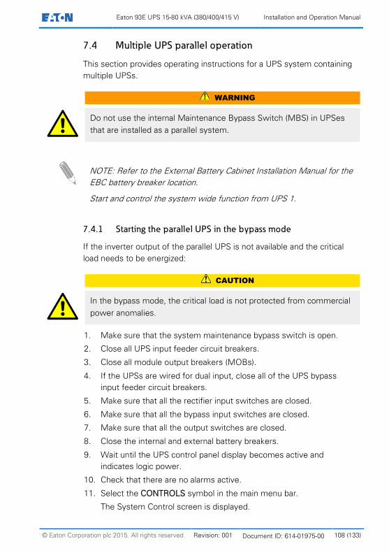
Eaton 93E UPS 15-80 kVA (380/400/415 V) Installation and Operation Manual
© Eaton Corporation plc 2015. All rights reserved. Revision: 001 Document ID: 614-01975-00 108 (133)
7.4 Multiple UPS parallel operation
This section provides operating instructions for a UPS system containing multiple UPSs.
WARNING
Do not use the internal Maintenance Bypass Switch (MBS) in UPSes that are installed as a parallel system.
NOTE: Refer to the External Battery Cabinet Installation Manual for the EBC battery breaker location.
Start and control the system wide function from UPS 1.
7.4.1 Starting the parallel UPS in the bypass mode
If the inverter output of the parallel UPS is not available and the critical load needs to be energized:
CAUTION
In the bypass mode, the critical load is not protected from commercial power anomalies.
1. Make sure that the system maintenance bypass switch is open.
2. Close all UPS input feeder circuit breakers.
3. Close all module output breakers (MOBs).
4. If the UPSs are wired for dual input, close all of the UPS bypass input feeder circuit breakers.
5. Make sure that all the rectifier input switches are closed.
6. Make sure that all the bypass input switches are closed.
7. Make sure that all the output switches are closed.
8. Close the internal and external battery breakers.
9. Wait until the UPS control panel display becomes active and indicates logic power.
10. Check that there are no alarms active.
11. Select the CONTROLS symbol in the main menu bar.
The System Control screen is displayed.
Eaton 93E UPS 15-80 kVA (380/400/415 V) Installation and Operation Manual
© Eaton Corporation plc 2015. All rights reserved. Revision: 001 Document ID: 614-01975-00 109 (133)
12. If not already selected, select UPS in the System Control screen.
13. In the UPS System Control screen, select the LOAD OFF → BYPASS command and press the push button.
The critical load is immediately supplied by the bypass source in the bypass mode from all the UPSs.
The bypass status indicator is illuminated.
7.4.2 Starting the parallel UPS in the standard normal mode (default mode)
To start the UPS system:
1. Make sure that the system maintenance bypass switch is open.
2. Close all UPS input feeder circuit breakers.
3. Close all module output breakers (MOBs).
4. If the UPSs are wired for dual input, close all of the UPSs bypass input feeder circuit breakers.
5. Make sure that all the rectifier input switches are closed.
6. Make sure that all the bypass input switches are closed.
7. Make sure that all the output switches are closed.
8. Close all internal and external battery breakers.
9. Wait until the UPS control panel display becomes active and indicates logic power.
10. Check that there are no alarms active.
11. Select the CONTROLS symbol in the main menu bar.
The System Control screen is displayed.
12. If not already selected, select UPS in the System Control screen.
13. In the UPS System Control screen, select the LOAD OFF → NORMAL command and press the push button.
14. If requested, enter the Level 1 password. The default Level 1 password is 1111.
After the password is entered, the UPS transfers first to bypass and the bypass LED is illuminated.
All rectifiers and inverters turn on. The inverters continue to ramp up to full voltage.
Eaton 93E UPS 15-80 kVA (380/400/415 V) Installation and Operation Manual
© Eaton Corporation plc 2015. All rights reserved. Revision: 001 Document ID: 614-01975-00 110 (133)
Once all the inverters have reached full voltage, the UPS output contactors close and the static switches turn off. The DC-link and the rectifier is turned on. The rectifier input relay closes while the DC-link continues to ramp up to full voltage. After this, the inverter is turned on, the UPS output relay closes and the static switch turns off.
Power is now supplied to the critical load in the standard normal mode. It takes approximately one minute for the UPS to achieve standard normal mode. The normal mode status indicator is illuminated.
7.4.3 Transfer from the normal mode to the bypass mode
To transfer the critical load to the bypass mode:
CAUTION
In the bypass mode, the critical load is not protected from commercial power anomalies.
1. Select the CONTROLS symbol in the main menu bar.
The System Control screen is displayed.
2. If not already selected, select UPS in the System Control screen.
3. In the UPS System Control screen, select the NORMAL → BYPASS command and press the push button.
All of the UPSs transfer to the bypass mode.
The bypass status indicator is illuminated. The power module remains on.
WARNING
Power is present inside the UPS cabinet.
7.4.4 Transfer from the bypass mode to the normal mode
To transfer the critical load to the normal mode:
1. Select the CONTROLS symbol in the main menu bar.
The System Control screen is displayed.
2. If not already selected, select UPS in the System Control screen.
Eaton 93E UPS 15-80 kVA (380/400/415 V) Installation and Operation Manual
© Eaton Corporation plc 2015. All rights reserved. Revision: 001 Document ID: 614-01975-00 111 (133)
3. In the UPS System Control screen, select the BYPASS → NORMAL command and press the push button.
All of the UPSs transfer to the normal mode. If the power module is not available, the system remains on bypass and an alarm sounds.
The normal mode status indicator is illuminated.
WARNING
Power is present inside the UPS cabinet.
7.4.5 Single UPS shutdown
To shut down the UPS:
1. Shut down the UPS.
2. Open the MOB for the UPS being shut down.
3. Select the CONTROLS symbol in the main menu bar.
The System Control screen is displayed.
4. If not already selected, select UPS in the System Control screen.
5. In the UPS System Control screen, select the NORMAL → UPS OFF command and press the push button.
The output and bypass backfeed relay open, and the power module is turned off on the UPS being shut down.
Logic power remains on.
WARNING
Power is present inside the UPS cabinet until the upstream input feeder circuit breaker is opened.
6. Open the UPS input and the bypass feeder circuit breakers for the UPS being shut down.
7. If EBCs are installed, open all the battery breakers.
The UPS is now completely shut down.
Eaton 93E UPS 15-80 kVA (380/400/415 V) Installation and Operation Manual
© Eaton Corporation plc 2015. All rights reserved. Revision: 001 Document ID: 614-01975-00 112 (133)
7.4.6 Single UPS restart
To restart a single UPS from a shutdown state:
1. Close the MOB for the UPS being restarted.
2. Close the UPS input and bypass feeder circuit breakers for the UPS being restarted.
3. Close the rectifier input switch.
4. If the UPSs are wired for dual input, close the bypass input switch.
5. Close the output switch.
6. Close the external battery breakers.
7. On the UPS being restarted, wait until the UPS control panel display becomes active and indicates logic power.
8. Check that there are no alarms active on the UPS being restarted.
9. On the UPS being restarted, select the CONTROLS symbol in the main menu bar.
The System Control screen is displayed.
10. If not already selected, select UPS in the System Control screen.
11. In the UPS System Control screen, select the UPS OFF → NORMAL command and press the push button.
12. If requested, enter the Level 1 password. The default password is 1111.
The rectifier and inverter turn on. The inverter continues to ramp up to full voltage.
Once the inverter reaches full voltage, the UPS output relay closes and the static switch turns off.
Power is now supplied to the critical load in the standard normal mode along with the other UPSs online. It takes approximately one minute for the UPS to achieve the standard normal mode.
The normal mode status indicator is illuminated.
7.4.7 UPS and critical load shutdown
To perform maintenance or service on the critical load, shut down power to the load:
1. Turn off all the equipment that is being powered by the UPS parallel system.
2. Transfer the UPSs to bypass by performing the procedure in Section 7.4.3.
Eaton 93E UPS 15-80 kVA (380/400/415 V) Installation and Operation Manual
© Eaton Corporation plc 2015. All rights reserved. Revision: 001 Document ID: 614-01975-00 113 (133)
3. Perform the LOAD OFF procedure as instructed in Section 7.4.10.
The output relay and the bypass backfeed contactor open, and the power module is turned off.
4. Perform the battery charger off procedure as instructed in Section 7.4.8 for each UPS.
The input and battery relay open.
WARNING
Power is present inside the UPS cabinets after the upstream input feeder circuit breakers are opened because of the installed external battery cabinet.
5. Open all the rectifier input input switches.
6. Open all the bypass input switches.
7. Open the output switch.
8. Open all the MOBs.
9. Open all the UPSs input and bypass feeder circuit breakers.
10. Open all the internal and external battery breakers.
7.4.8 Charger control
To turn an individual UPS battery charger on:
1. Select the CONTROLS symbol in the main menu bar on the UPS requiring the charger to be turned on.
The System Control screen is displayed.
2. Select Battery in the System Control screen
3. In the Battery System Control screen, select the RESTING → CHARGING command and press the push button.
To turn an individual UPS battery charger off:
1. Select the CONTROLS symbol in the main menu bar on the UPS requiring the charger to be turned off.
The System Control screen is displayed.
2. Select Battery in the System Control screen.
3. In the Battery System Control screen, select the CHARGING → RESTING command and press the push button.
Eaton 93E UPS 15-80 kVA (380/400/415 V) Installation and Operation Manual
© Eaton Corporation plc 2015. All rights reserved. Revision: 001 Document ID: 614-01975-00 114 (133)
7.4.9 Battery test
NOTE: This UPS has a user initiated battery test intended to determine if the batteries are able to support the load.
The battery test is only able to be initiated when the battery is fully charged. This normally occurs within 72 hours of the start of a charging cycle. The command will not be shown if the test is not able to be run.
To start an individual UPS battery test:
1. Select the CONTROLS symbol in the main menu bar on the UPS to be tested.
The System Control screen is displayed.
2. Select Battery in the System Control screen.
3. In the Battery System Control screen, select the RESTING → TESTING command and press the push button.
7.4.10 Using the UPS LOAD OFF command
A UPS Load Off is initiated by selecting the Load Off command in the UPS Control screen. The UPS LOAD OFF controls the UPSs output by powering down the UPS and de-energizing the critical load.
The UPSs (including bypass) remains off until restarted.
To use the LOAD OFF command:
1. Select the CONTROLS symbol in the main menu bar on the UPS to be shut down.
The System Control screen is displayed.
2. Select UPS in the System Control screen.
3. In the UPS System Control screen, select the NORMAL → LOAD OFF or BYPASS → LOAD OFF command depending on the UPS mode, then press the push button.
The Verify Action screen is displayed, providing you with a choice to proceed or abort the shutdown.
Eaton 93E UPS 15-80 kVA (380/400/415 V) Installation and Operation Manual
© Eaton Corporation plc 2015. All rights reserved. Revision: 001 Document ID: 614-01975-00 115 (133)
CAUTION
All power to the critical load is lost when the LOAD OFF is selected in the following step. You should use this feature only when you want to de-energize the critical load.
4. Select Yes or No and press the push button.
Selecting Yes immediately shuts down the UPS and de-energizes the critical load. Selecting No aborts the shutdown.
5. If another UPS is to be shut down, proceed to that UPS and repeat Step 1 through Step 4.
CAUTION
Do not attempt to restart the system after Load Off until the cause of the shutdown has been identified and cleared.
6. To restart the UPS after pressing the LOAD OFF push button, follow the procedure in Section 6.4.1 or 6.4.2.
WARNING
Power is present inside the UPS cabinet after the upstream input feeder circuit breakers are opened because of the installed external battery cabinet.
7.4.11 Using the remote emergency power-off switch
A UPS emergency power-off is initiated by the remote EPO push button switch. In case of an emergency, you can use this switch to control the UPS output. The remote EPO switch de-energizes the critical load and powers down the UPS immediately, without asking for verification.
The UPSs, including bypass, remains off until restarted.
CAUTION
All power to the critical load is lost when the remote EPO switch is activated. Only use this feature when you want to de-energize the critical load.
Eaton 93E UPS 15-80 kVA (380/400/415 V) Installation and Operation Manual
© Eaton Corporation plc 2015. All rights reserved. Revision: 001 Document ID: 614-01975-00 116 (133)
NOTE: The following instructions are for the Eaton-supplied remote EPO switch. If a customer-supplied remote EPO switch is used, it may not activate in the same manner. Refer to the operating instructions provided with the switch.
To use the remote EPO switch:
1. Firmly push the red pushbutton until it locks into place. The switch latches into the activated state.
The input, output and battery relay and the optional bypass backfeed contactor open, and the power module is turned off immediately, without asking for verification.
CAUTION
Do not attempt to restart the system after the remote EPO until the cause of the shutdown has been identified and cleared.
2. To deactivate the remote EPO switch in preparation for restarting the UPS, insert the supplied key and rotate clockwise until the red pushbutton releases. To remove the key, rotate the key back to the vertical position.
3. Restart the UPS by following the procedure in Section 7.4.1 or 7.4.1.
WARNING
Power is present inside the UPS cabinet after the upstream input feeder circuit breakers are opened because of the installed external battery cabinet.
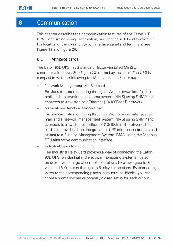
Eaton 93E UPS 15-80 kVA (380/400/415 V) Installation and Operation Manual
© Eaton Corporation plc 2015. All rights reserved. Revision: 001 Document ID: 614-01975-00 117 (133)
8 Communication
This chapter describes the communication features of the Eaton 93E UPS. For terminal wiring information, see Section 4.3.3 and Section 5.3. For location of the communication interface panel and terminals, see Figure 19 and Figure 20.
8.1 MiniSlot cards
The Eaton 93E UPS has 2 standard, factory-installed MiniSlot communication bays. See Figure 20 for the bay locations. The UPS is compatible with the following MiniSlot cards (see Figure 43):
• Network Management MiniSlot card
Provides remote monitoring through a Web browser interface, e-mail, and a network management system (NMS) using SNMP and connects to a twisted-pair Ethernet (10/100BaseT) network.
• Network and Modbus MiniSlot card
Provides remote monitoring through a Web browser interface, e-mail, and a network management system (NMS) using SNMP and connects to a twisted-pair Ethernet (10/100BaseT) network. The card also provides direct integration of UPS information (meters and status) to a Building Management System (BMS) using the Modbus RTU alternative communication interface.
• Industrial Relay Mini-Slot card
The Industrial Relay Card provides a way of connecting the Eaton 93E UPS to industrial and electrical monitoring systems. It also enables a wide range of control applications by allowing up to 250 volts and 5 Amperes through its 5 relay connections. By connecting wires to the corresponding places in its terminal blocks, you can choose normally-open or normally-closed setup for each output.
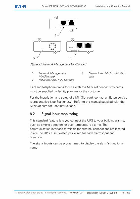
Eaton 93E UPS 15-80 kVA (380/400/415 V) Installation and Operation Manual
© Eaton Corporation plc 2015. All rights reserved. Revision: 001 Document ID: 614-01975-00 118 (133)
Figure 43. Network Management MiniSlot card
1. Network Management MiniSlot card
2. Industrial Relay Mini-Slot card
3. Network and Modbus MiniSlot card
LAN and telephone drops for use with the MiniSlot connectivity cards must be supplied by facility planners or the customer.
For the installation and setup of a MiniSlot card, contact an Eaton service representative (see Section 2.7). Refer to the manual supplied with the MiniSlot card for user instructions.
8.2 Signal input monitoring
This standard feature lets you connect the UPS to your building alarms, such as smoke detectors or over-temperature alarms. The communication interface terminals for external connections are located inside the UPS. Use twisted-pair wires for each alarm input and common.
The signal inputs can be programmed to display the alarm’s functional name.
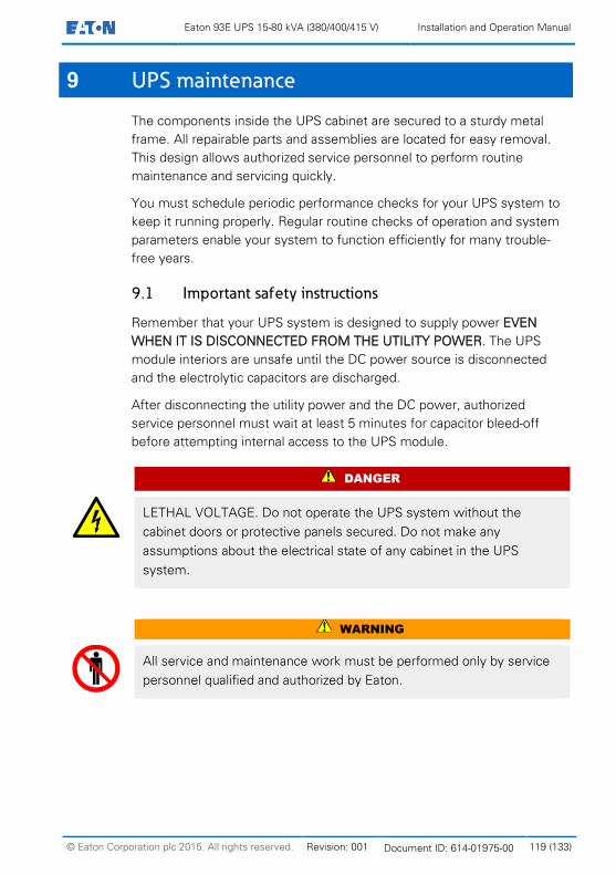
Eaton 93E UPS 15-80 kVA (380/400/415 V) Installation and Operation Manual
© Eaton Corporation plc 2015. All rights reserved. Revision: 001 Document ID: 614-01975-00 119 (133)
9 UPS maintenance
The components inside the UPS cabinet are secured to a sturdy metal frame. All repairable parts and assemblies are located for easy removal. This design allows authorized service personnel to perform routine maintenance and servicing quickly.
You must schedule periodic performance checks for your UPS system to keep it running properly. Regular routine checks of operation and system parameters enable your system to function efficiently for many trouble-free years.
9.1 Important safety instructions
Remember that your UPS system is designed to supply power EVEN WHEN IT IS DISCONNECTED FROM THE UTILITY POWER. The UPS module interiors are unsafe until the DC power source is disconnected and the electrolytic capacitors are discharged.
After disconnecting the utility power and the DC power, authorized service personnel must wait at least 5 minutes for capacitor bleed-off before attempting internal access to the UPS module.
. DANGER
LETHAL VOLTAGE. Do not operate the UPS system without the cabinet doors or protective panels secured. Do not make any assumptions about the electrical state of any cabinet in the UPS system.
WARNING
All service and maintenance work must be performed only by service personnel qualified and authorized by Eaton.
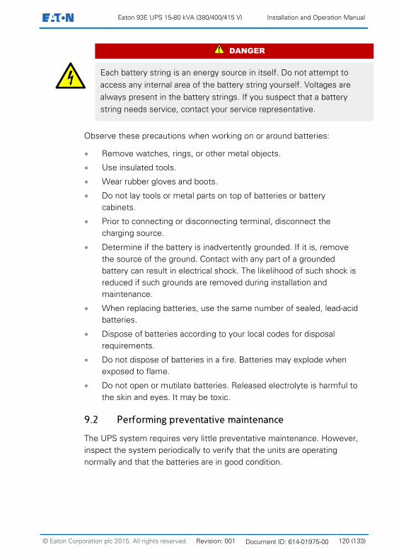
Eaton 93E UPS 15-80 kVA (380/400/415 V) Installation and Operation Manual
© Eaton Corporation plc 2015. All rights reserved. Revision: 001 Document ID: 614-01975-00 120 (133)
. DANGER
Each battery string is an energy source in itself. Do not attempt to access any internal area of the battery string yourself. Voltages are always present in the battery strings. If you suspect that a battery string needs service, contact your service representative.
Observe these precautions when working on or around batteries:
• Remove watches, rings, or other metal objects.
• Use insulated tools.
• Wear rubber gloves and boots.
• Do not lay tools or metal parts on top of batteries or battery cabinets.
• Prior to connecting or disconnecting terminal, disconnect the charging source.
• Determine if the battery is inadvertently grounded. If it is, remove the source of the ground. Contact with any part of a grounded battery can result in electrical shock. The likelihood of such shock is reduced if such grounds are removed during installation and maintenance.
• When replacing batteries, use the same number of sealed, lead-acid batteries.
• Dispose of batteries according to your local codes for disposal requirements.
• Do not dispose of batteries in a fire. Batteries may explode when exposed to flame.
• Do not open or mutilate batteries. Released electrolyte is harmful to the skin and eyes. It may be toxic.
9.2 Performing preventative maintenance
The UPS system requires very little preventative maintenance. However, inspect the system periodically to verify that the units are operating normally and that the batteries are in good condition.
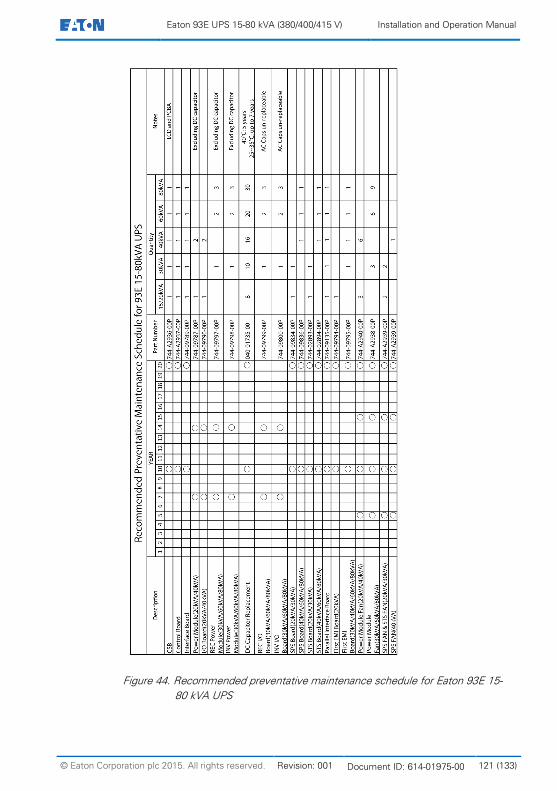
Eaton 93E UPS 15-80 kVA (380/400/415 V) Installation and Operation Manual
© Eaton Corporation plc 2015. All rights reserved. Revision: 001 Document ID: 614-01975-00 121 (133)
Figure 44. Recommended preventative maintenance schedule for Eaton 93E 15-
80 kVA UPS
Eaton 93E UPS 15-80 kVA (380/400/415 V) Installation and Operation Manual
© Eaton Corporation plc 2015. All rights reserved. Revision: 001 Document ID: 614-01975-00 122 (133)
9.2.1 Daily maintenance
Perform the following steps daily:
1. Check the area surrounding the UPS system. Make sure that the area is not cluttered, allowing free access to the unit.
2. Check that the air intakes (vents on the front door of the UPS cabinet) and the exhaust openings (at the rear of the UPS cabinet) are not blocked.
3. Make sure that the operating environment is within the parameters specified in Section 4.3.1 and Chapter 10.
4. Check that the UPS is in the normal mode (the normal mode status indicator is illuminated). If an alarm lamp is illuminated or the normal mode status indicator is not illuminated, contact an Eaton service representative.
9.2.2 Monthly maintenance
Perform the following steps monthly:
1. Check the system parameters as described in Section 7.2.
2. Check the UPS air filters (located behind the front door) and wash or replace them as necessary. See Figure 45 for the filter location. Contact your Eaton service representative for replacement filters. To remove the filters:
CAUTION
Make sure that a washed filter is thoroughly dry before reinstalling it.
a. To unfasten the front door, lift the latch from the bottom, turning it to the right (counter-clockwise) and swing the door open (see Figure 35).
b. Remove the upper and lower foam filters from the frame on the front door.
c. Replace the washed or new foam filters into the frame on the front door.
d. Close the front door and secure the latch.
3. Record the maintenance results and any corrective actions in a suitable log.
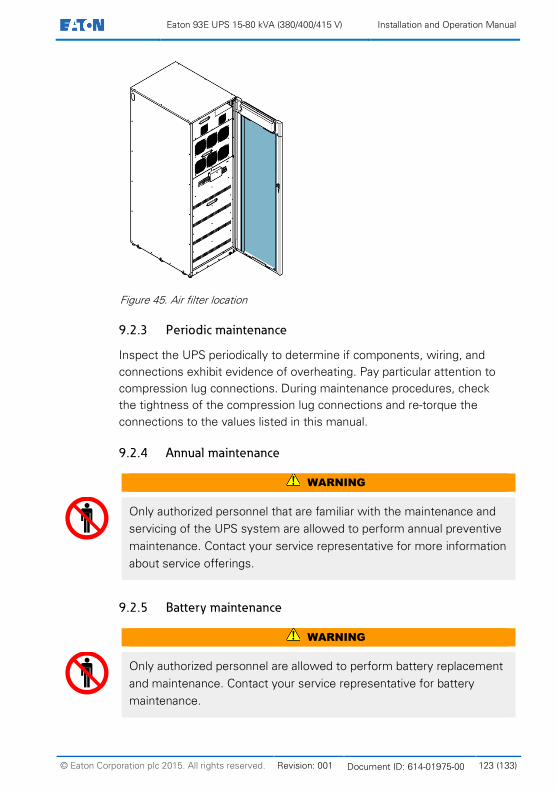
Eaton 93E UPS 15-80 kVA (380/400/415 V) Installation and Operation Manual
© Eaton Corporation plc 2015. All rights reserved. Revision: 001 Document ID: 614-01975-00 123 (133)
Figure 45. Air filter location
9.2.3 Periodic maintenance
Inspect the UPS periodically to determine if components, wiring, and connections exhibit evidence of overheating. Pay particular attention to compression lug connections. During maintenance procedures, check the tightness of the compression lug connections and re-torque the connections to the values listed in this manual.
9.2.4 Annual maintenance
WARNING
Only authorized personnel that are familiar with the maintenance and servicing of the UPS system are allowed to perform annual preventive maintenance. Contact your service representative for more information about service offerings.
9.2.5 Battery maintenance
WARNING
Only authorized personnel are allowed to perform battery replacement and maintenance. Contact your service representative for battery maintenance.
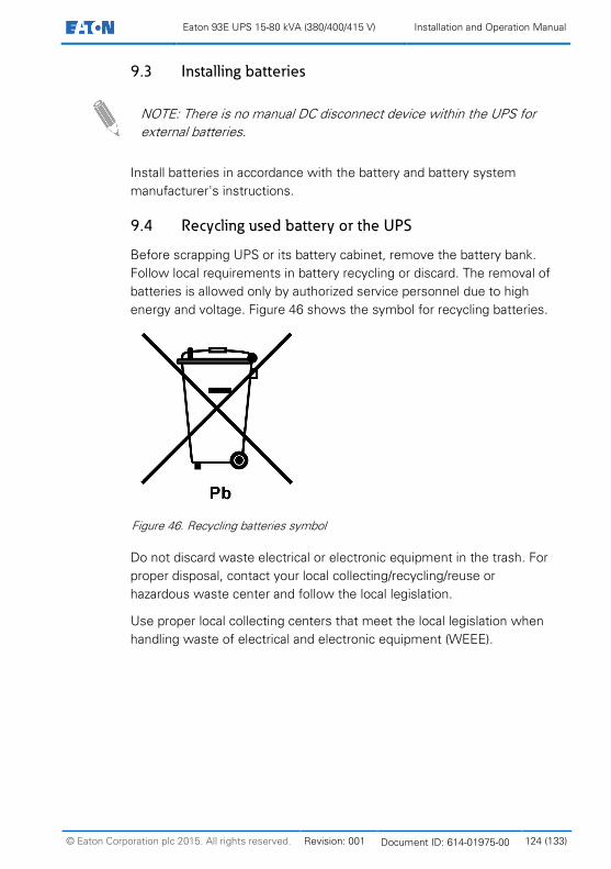
Eaton 93E UPS 15-80 kVA (380/400/415 V) Installation and Operation Manual
© Eaton Corporation plc 2015. All rights reserved. Revision: 001 Document ID: 614-01975-00 124 (133)
9.3 Installing batteries
NOTE: There is no manual DC disconnect device within the UPS for external batteries.
Install batteries in accordance with the battery and battery system manufacturer's instructions.
9.4 Recycling used battery or the UPS
Before scrapping UPS or its battery cabinet, remove the battery bank. Follow local requirements in battery recycling or discard. The removal of batteries is allowed only by authorized service personnel due to high energy and voltage. Figure 46 shows the symbol for recycling batteries.
Figure 46. Recycling batteries symbol
Do not discard waste electrical or electronic equipment in the trash. For proper disposal, contact your local collecting/recycling/reuse or hazardous waste center and follow the local legislation.
Use proper local collecting centers that meet the local legislation when handling waste of electrical and electronic equipment (WEEE).
Eaton 93E UPS 15-80 kVA (380/400/415 V) Installation and Operation Manual
© Eaton Corporation plc 2015. All rights reserved. Revision: 001 Document ID: 614-01975-00 125 (133)
Figure 47. WEEE symbol
. DANGER
HAZARDOUS MATERIALS. Batteries may contain high voltages, and caustic, toxic and flammable substances. If used improperly, batteries can injure or kill people and damage equipment. Do not discard unwanted batteries or battery material in the public waste disposal system. Follow all the applicable local regulations for storage, handling and disposal of batteries and battery materials.
9.5 Maintenance training
A basic training course, available from Eaton Corporation, gives you a competent working knowledge of the UPS system operation and teaches you how to perform first level corrective maintenance. For more information about training and other services, contact your Eaton representative (see Section 2.7).
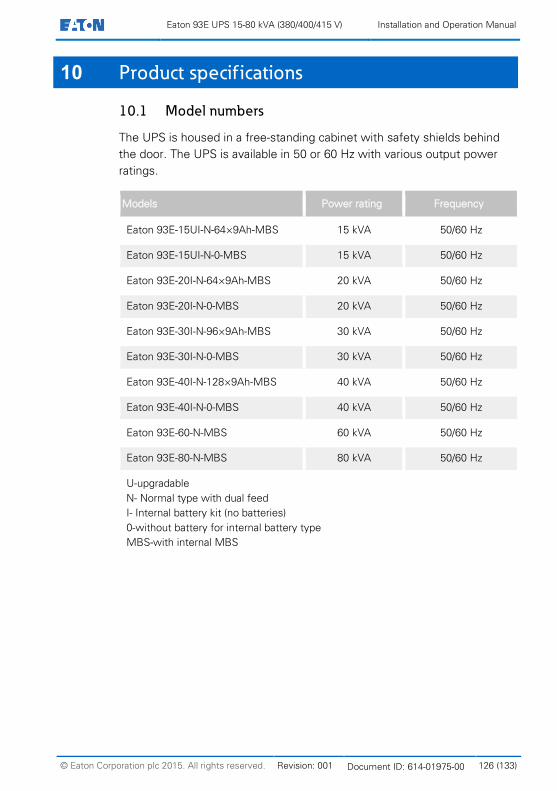
Eaton 93E UPS 15-80 kVA (380/400/415 V) Installation and Operation Manual
© Eaton Corporation plc 2015. All rights reserved. Revision: 001 Document ID: 614-01975-00 126 (133)
10 Product specifications
10.1 Model numbers
The UPS is housed in a free-standing cabinet with safety shields behind the door. The UPS is available in 50 or 60 Hz with various output power ratings.
Models Power rating Frequency
Eaton 93E-15UI-N-64×9Ah-MBS 15 kVA 50/60 Hz
Eaton 93E-15UI-N-0-MBS 15 kVA 50/60 Hz
Eaton 93E-20I-N-64×9Ah-MBS 20 kVA 50/60 Hz
Eaton 93E-20I-N-0-MBS 20 kVA 50/60 Hz
Eaton 93E-30I-N-96×9Ah-MBS 30 kVA 50/60 Hz
Eaton 93E-30I-N-0-MBS 30 kVA 50/60 Hz
Eaton 93E-40I-N-128×9Ah-MBS 40 kVA 50/60 Hz
Eaton 93E-40I-N-0-MBS 40 kVA 50/60 Hz
Eaton 93E-60-N-MBS 60 kVA 50/60 Hz
Eaton 93E-80-N-MBS 80 kVA 50/60 Hz
U-upgradable N- Normal type with dual feed I- Internal battery kit (no batteries) 0-without battery for internal battery type MBS-with internal MBS
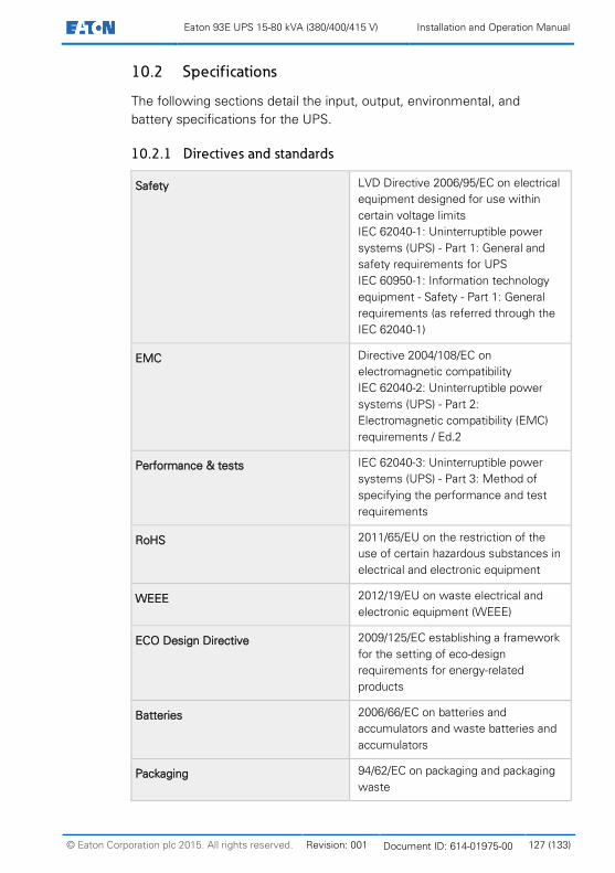
Eaton 93E UPS 15-80 kVA (380/400/415 V) Installation and Operation Manual
© Eaton Corporation plc 2015. All rights reserved. Revision: 001 Document ID: 614-01975-00 127 (133)
10.2 Specifications
The following sections detail the input, output, environmental, and battery specifications for the UPS.
10.2.1 Directives and standards
Safety LVD Directive 2006/95/EC on electrical equipment designed for use within certain voltage limits IEC 62040-1: Uninterruptible power systems (UPS) - Part 1: General and safety requirements for UPS IEC 60950-1: Information technology equipment - Safety - Part 1: General requirements (as referred through the IEC 62040-1)
EMC Directive 2004/108/EC on electromagnetic compatibility IEC 62040-2: Uninterruptible power systems (UPS) - Part 2: Electromagnetic compatibility (EMC) requirements / Ed.2
Performance & tests IEC 62040-3: Uninterruptible power systems (UPS) - Part 3: Method of specifying the performance and test requirements
RoHS 2011/65/EU on the restriction of the use of certain hazardous substances in electrical and electronic equipment
WEEE 2012/19/EU on waste electrical and electronic equipment (WEEE)
ECO Design Directive 2009/125/EC establishing a framework for the setting of eco-design requirements for energy-related products
Batteries 2006/66/EC on batteries and accumulators and waste batteries and accumulators
Packaging 94/62/EC on packaging and packaging waste
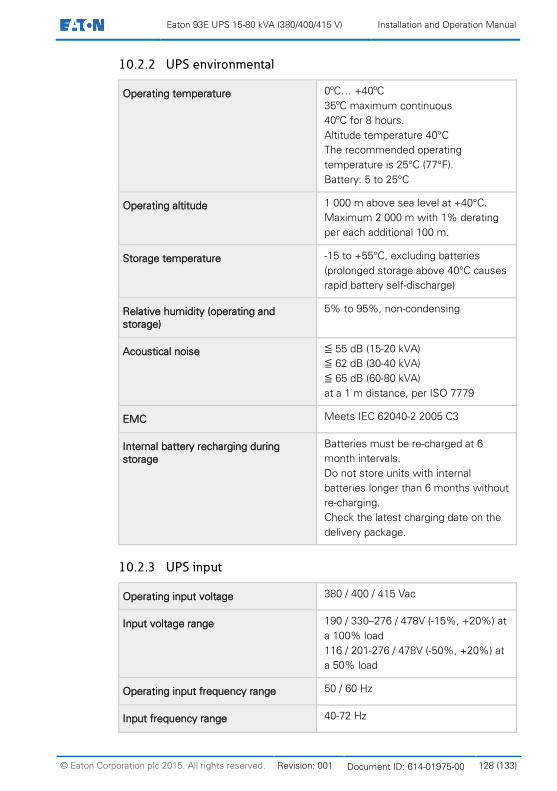
Eaton 93E UPS 15-80 kVA (380/400/415 V) Installation and Operation Manual
© Eaton Corporation plc 2015. All rights reserved. Revision: 001 Document ID: 614-01975-00 128 (133)
10.2.2 UPS environmental
Operating temperature 0ºC… +40ºC 35ºC maximum continuous 40ºC for 8 hours. Altitude temperature 40°C The recommended operating temperature is 25°C (77°F). Battery: 5 to 25°C
Operating altitude 1 000 m above sea level at +40°C. Maximum 2 000 m with 1% derating per each additional 100 m.
Storage temperature -15 to +55°C, excluding batteries (prolonged storage above 40°C causes rapid battery self-discharge)
Relative humidity (operating and storage)
5% to 95%, non-condensing
Acoustical noise ≦ 55 dB (15-20 kVA) ≦ 62 dB (30-40 kVA) ≦ 65 dB (60-80 kVA) at a 1 m distance, per ISO 7779
EMC Meets IEC 62040-2 2005 C3
Internal battery recharging during storage
Batteries must be re-charged at 6 month intervals. Do not store units with internal batteries longer than 6 months without re-charging. Check the latest charging date on the delivery package.
10.2.3 UPS input
Operating input voltage 380 / 400 / 415 Vac
Input voltage range 190 / 330–276 / 478V (-15%, +20%) at a 100% load 116 / 201-276 / 478V (-50%, +20%) at a 50% load
Operating input frequency range 50 / 60 Hz
Input frequency range 40-72 Hz
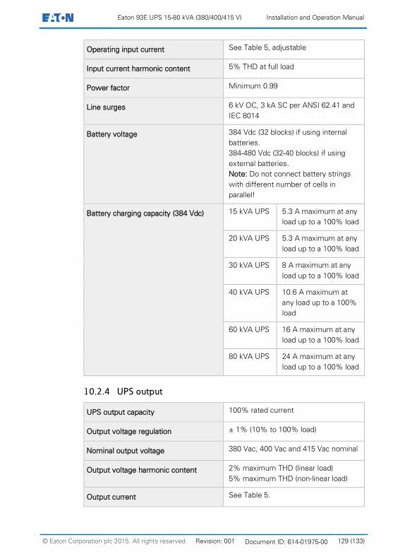
Eaton 93E UPS 15-80 kVA (380/400/415 V) Installation and Operation Manual
© Eaton Corporation plc 2015. All rights reserved. Revision: 001 Document ID: 614-01975-00 129 (133)
Operating input current See Table 5, adjustable
Input current harmonic content 5% THD at full load
Power factor Minimum 0.99
Line surges 6 kV OC, 3 kA SC per ANSI 62.41 and IEC 8014
Battery voltage 384 Vdc (32 blocks) if using internal batteries. 384-480 Vdc (32-40 blocks) if using external batteries. Note: Do not connect battery strings with different number of cells in parallel!
Battery charging capacity (384 Vdc) 15 kVA UPS 5.3 A maximum at any load up to a 100% load
20 kVA UPS 5.3 A maximum at any load up to a 100% load
30 kVA UPS 8 A maximum at any load up to a 100% load
40 kVA UPS 10.6 A maximum at any load up to a 100% load
60 kVA UPS 16 A maximum at any load up to a 100% load
80 kVA UPS 24 A maximum at any load up to a 100% load
10.2.4 UPS output
UPS output capacity 100% rated current
Output voltage regulation ± 1% (10% to 100% load)
Nominal output voltage 380 Vac, 400 Vac and 415 Vac nominal
Output voltage harmonic content 2% maximum THD (linear load) 5% maximum THD (non-linear load)
Output current See Table 5.
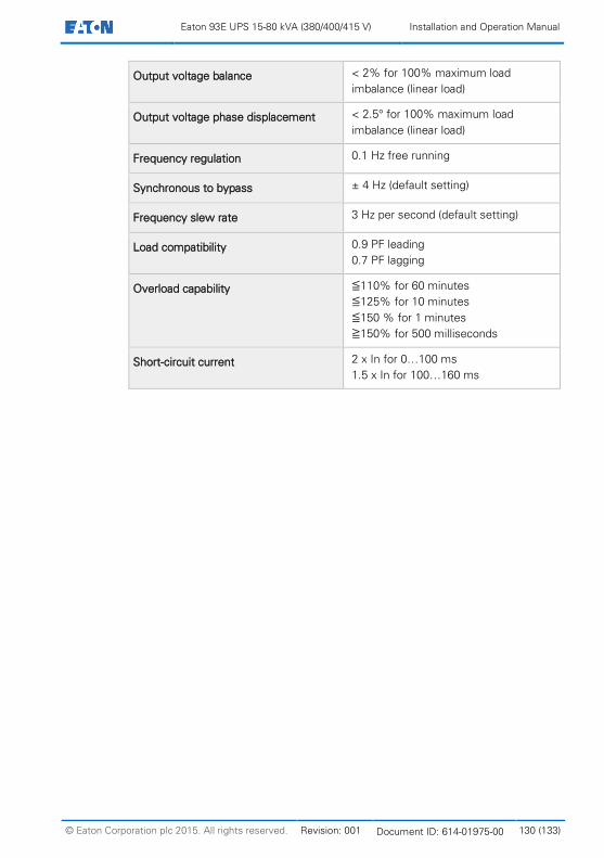
Eaton 93E UPS 15-80 kVA (380/400/415 V) Installation and Operation Manual
© Eaton Corporation plc 2015. All rights reserved. Revision: 001 Document ID: 614-01975-00 130 (133)
Output voltage balance < 2% for 100% maximum load imbalance (linear load)
Output voltage phase displacement < 2.5° for 100% maximum load imbalance (linear load)
Frequency regulation 0.1 Hz free running
Synchronous to bypass ± 4 Hz (default setting)
Frequency slew rate 3 Hz per second (default setting)
Load compatibility 0.9 PF leading 0.7 PF lagging
Overload capability ≦110% for 60 minutes ≦125% for 10 minutes ≦150 % for 1 minutes ≧150% for 500 milliseconds
Short-circuit current 2 x In for 0…100 ms 1.5 x In for 100…160 ms
Eaton 93E UPS 15-80 kVA (380/400/415 V) Installation and Operation Manual
© Eaton Corporation plc 2015. All rights reserved. Revision: 001 Document ID: 614-01975-00 131 (133)
11 Warranty
11.1 General
The product is warranted against defects in materials and workmanship for a period of twelve (12) months from its original date of purchase. The local office or distributor may grant a warranty period different to the above. Please refer to local terms of liability as defined in the supply contract.
The UPS manufacturer is not responsible for:
• Any costs resulting from a failure if the installation, commissioning, repair, alternation, or ambient conditions of the equipment do not fulfil the requirements specified in the documentation delivered with the unit and other relevant documentation.
• Equipment subjected to misuse, negligence or accident.
• Equipment comprised of materials provided or designs stipulated by the purchaser.
The warranty is only valid if the installation inspection and initial startup of the UPS unit is carried out by a service engineer approved by Eaton. Service and maintenance of the UPS shall also be performed only by a service engineer approved by Eaton. Otherwise the warranty will be voided.
If the product fails to meet its published specifications due to a defect in material and workmanship, covered by this warranty, the seller will repair or replace the warranted product. Such repair or replacement will be made by Eaton or by a service provider approved by Eaton. Repair or replacement during the warranty period does not extend the original warranty. Warranty does not cover taxes, which will be due in connection with replacement or repair of the product.
Batteries are warranted against failures in material and workmanship, not against the normal aging and reduction of ampere-hour capacity. The product storage environment has to meet manufacturer's specifications, failure to do this will cause the warranty to be voided.
Under no circumstances shall the manufacturer, its suppliers or subcontractors be liable for special, indirect, incidental or consequential damages, losses or penalties.
Eaton 93E UPS 15-80 kVA (380/400/415 V) Installation and Operation Manual
© Eaton Corporation plc 2015. All rights reserved. Revision: 001 Document ID: 614-01975-00 132 (133)
The technical data, information and specifications are valid at the time of printing. The UPS manufacturer reserves the right to modifications without prior notice.
11.2 Whom to contact in case of Warranty
In case of Warranty, or while unsure if the unit in question is covered by warranty, contact the respective sales organization where the unit was purchased. Have the following information available:
• Purchase order number and purchase order date
• Installation date
OR
• Serial number and part number of the unit (information available on the unit's label)


Cop
yrig
ht ©
201
5 E
aton
Cor
pora
tion
plc.
All
right
s re
serv
ed. U
naut
horiz
ed c
opyi
ng a
nd le
ndin
g ar
e pr
ohib
ited.
Eaton Power Quality Oy Koskelontie 13 FI02920 Espoo
Finland www.eaton.eu


![Øô â4 93E éÄD×mL[Y ûî ¶Ü¿ ªXhÈU ô|Ïtù?¯!home.ustc.edu.cn/~kyu/kejian/chp01.protected.pdf · Title °.]Øô â4 93E éÄD×mL[Y ûî ¶Ü¿ ªXhÈU ô|Ïtù?¯! Author:](https://static.fdocuments.net/doc/165x107/5e7fd22ccef677391c1d3ffe/-4-93e-dmly-oe-xhu-thomeustceducnkyukejianchp01.jpg)
