INSTALLATION AND OPERATING INSTRUCTIONS and operating instructions ducted system record this unit...
13
Roof Top Air Conditioner INSTALLATION AND OPERATING INSTRUCTIONS Ducted System RECORD THIS UNIT INFORMATION FOR FUTURE REFERENCE: Model Number: Serial Number: Date Purchased: This manual must be read and understood before installation, adjustment, service, or maintenance is performed. This unit must be installed by a qualified service technician. Modification of this product can be extremely hazardous and could result in personal injury or property damage.
Transcript of INSTALLATION AND OPERATING INSTRUCTIONS and operating instructions ducted system record this unit...

Roof Top Air Conditioner
INSTALLATION AND OPERATING INSTRUCTIONS
Ducted System RECORD THIS UNIT INFORMATION FOR FUTURE REFERENCE: Model Number: Serial Number: Date Purchased:
This manual must be read and understood before installation, adjustment, service, or maintenance
is performed. This unit must be installed by a qualified service technician. Modification of this product can be extremely hazardous and could result in personal injury or property damage.

2
INSTALLATION & OPERATING INSTRUCTIONS
These instructions must stay with the unit Safety Instructions This manual has safety information and instructions to help users eliminate or reduce the risk of accidents and injuries. Read and follow all safety information, installation guides, recommended precautions, and safe operating instructions. GENERAL INFORMATION A. This air conditioner is designed for:
1. Installation on a recreational vehicle. 2. Mounting on the roof of a recreational vehicle. 3. Roof construction with rafters/joists on 16 inch centers. 4. 2.5” to 5” inch thick roofs.
B. The efficiency of the air conditioner will be affected by the conditions inside and outside of the RV. Reducing the heat gain of the RV will allow the air conditioner to function with greater efficiency. Here are some suggestions to reduce heat gain in your RV.
1. Select a shaded area to park your RV 2. Close windows and utilize the blinds and/or curtains. 3. Keep doors shut. 4. Avoid using appliances that produce heat.
Beginning the cooling process early in the day will greatly improve the air conditioner’s ability to maintain the desired temperature. In high temperature and high humidity environments, the AC should be set in Cool mode with the Fan Speed in the high position. This will allow for optimal cooling efficiency. C. Condensation The manufacturer of this air conditioner will not be responsible for damage caused by condensed moisture on ceilings or other surfaces. Air contains moisture and this moisture tends to condense on cold surfaces. When air enters the RV, condensed moisture may appear on the ceiling, windows, metal parts, etc. The air conditioner removes this moisture from the air during normal operation. Keeping doors and windows closed when this air conditioner is operating will minimize condensation.
COOL
Model BTU/HR Electrical Rating
Compressor rated load (Amps)
Compressor locked rotor (Amps)
Fan motor rated load (Amps)
Fan motor locked rotor (Amps)
Air flow (High speed) ( m3/h)
Refrigerant (R410a) (gr.)
Min.wire size
AC circuit protection (User supplied)
Unit dimensions (in)
Weight (lbs)
AC135 13500 12.4 61 2.5 5.8 580 500 20Amp 35.1x29.9x13.2" 86
AC150 15000
115VAC 60HZ 1PH 13.5 66 2.5 5.8 580 520
12AWG copper up to 24' 20Amp 35.1x29.9x13.2" 90

3
Notes:
1. Consult the National Electric Code for proper sizing for wire lengths over 24 ft. 2. When sizing the generator, the total power usage of your recreational vehicle must be
considered. Keep in mind generators lose power at high altitudes and from lack of maintenance.
3. CIRCUIT PROTECTION: Time Delay Fuse or HACR Circuit Breakers Required.
INSTALLATION INSTRUCTIONS 1. PRECAUTIONS
A. Read installation and operating instructions carefully before attempting to start your air conditioner installation.
B. The manufacturer will not be liable for any damages or injury incurred due to failure to follow these instructions.
C. Installation must comply with the National Electrical Code and any State or Local Codes or regulations.
D. DO NOT add any devices or accessories to this air conditioner except those specifically authorized by manufacturer.
E. This equipment must be serviced by qualified personnel and some states require licensed personnel.
2. CHOOSING A LOCATION FOR THE AIR CONDITIONER This product is designed for use as a RV roof top air conditioner. The use of this product in
other applications will void the manufactures warranty.
A. NORMAL LOCATIONS: The air conditioner is designed to fit over an existing roof vent opening. When the vent is
removed, it normally creates a 14-1/4" x 14-1/4" ±1/8” opening.
B. OTHER LOCATIONS: When a roof vent is not available or another location is desired, the following is recommended:

4
1. For one unit installation: The air conditioner should be mounted slightly forward of center (front to back) and centered from side to side. See Figure 1
Figure 1
2. For two unit installation: Install one air conditioner 1/3 distance and the other air conditioner 2/3's from front of RV and centered from side to side. See Figure 2
Figure 2
It is preferred that this air conditioner be installed in a relatively flat and level roof section measured with the RV parked on a level surface; however, up to 15° slant to either side, or front-to-back is acceptable.

5
C. POST LOCATION SELECTION:
1. Check for obstructions in the area where air conditioner will be installed. 2. The roof must be capable of supporting 130lbs while the RV is in motion.
Normally, a 200 lb. static load design will meet this requirement.
3. ROOF PREPARATION
A. EXISTING ROOF VENT REMOVAL:
1. Unscrew and remove the roof vent. 2. Remove all caulking compound around opening. 3. Seal all screw holes and seams where the roof gasket will be located. Use a good
grade of all weather sealant. B. NEW OPENING:
1. A 14-1/4" x 14-1/4"±1/8” opening must be cut through the roof and ceiling of the RV. It is recommended this opening be located between roof framework.
2. Mark a 14-1/4" x 14-1/4" square on the roof and carefully cut the opening. 3. Using the roof opening as a guide, cut the matching hole in the ceiling. See FIG.4.

6
C. OPENING PREPARATION:
1. If the opening exceeds 14-3/8" x 14-3/8", it will be necessary to install spacers. 2. If the opening is less than 14-1/8" x 14-1/8", it must be enlarged. 3. Route a 12/3 Romex type supply line from the fuse or circuit breaker box to the front of
roof opening. a. The power supply must be on a separate 20 amp Time Delay Fuse or HACR
Circuit Breaker. b. Wiring must comply with all National, State and Local wiring codes. c. Make sure at least 15" of wire extend into the roof opening to ensure easy
connections.
4. The opening must be framed to provide adequate support and prevent air from being drawn from the roof cavity. Lumber 3/4" thick or more and long enough to bridge the opening must be used. Remember to provide an entrance hole in the front of the opening for 110v, 12v, and thermostat wires. See FIG. 5.
5. The 14-1/4" x 14-1/4"(±1/8) roof opening is part of the return air duct and must be finished
in accordance with NFPA standard 501C, Standard for Recreational Vehicles, Section 2-7.
It is the responsibility of the installer of this air conditioner system to ensure structural integrity of the RV roof. Never create a low spot on the roof where
water will collect. Water standing around the air conditioner may leak into the interior causing damage to the product and RV

7
AIR CONDITIONER RETURN GRILL (ACRG) INSTALLATION The Air Return Grill is designed for application in systems that utilize field fabricated (OEM supplied) air ducting. The ducting must be routed through the ceiling cavity (between the interior ceiling and roof). Ducting specifications are given in the section labeled “Supply Ducting and Registers”. ACRG INSTALLATION REQUIREMENTS (ROOF THICKNESS MUST BE AT LEAST 2.5")
1. The ACRG must be installed under the roof opening. The ACRG bolts to the underside of the roof unit. Compression of the framed ceiling cavity between the roof unit and the ACRG is what holds both components in place.
2. Ceiling cavity depth (the measurement from the ceiling to the roof): 5" – Maximum, 2.5" - Minimum
3. The 115 VAC service for the roof unit must be routed into the ACRG (refer to the wiring diagram below). 12VDC and furnace thermostat wires should be routed to the analog control box.
4.The ACRG has a 6 pin and a 3 pin connector optional with heat kit extending from 4.
5. The ACRG has 6 pin ( and a 3pin connector optional with the heat kit) extending from the front of the electrical box. These connectors mate with the roof unit. When making this connection, verify that the plugs are properly aligned and have snapped together securely. See Figure 5a Figure 5a
6. Provided with the ACRG, is a divider plate which is used to separate the warm return air
from the cold supply air. If the roof thickness is greater than 2.5”, you can use the additional divider provided.
SUPPLY DUCTING AND REGISTERS A. Ducting
1. The field fabricated supply ducting must attach to both sides of the ACRG. A minimum of two ducts are required, with one duct attached to each side of the plenum.
2. Each duct must have a minimum height of 1-1/2". Maximum height cannot exceed 4”. Total free area inside each duct must be no less than 10 square inches.

8
NOTE: To decrease restriction and increase airflow, the ducting should make as few bends and turns as possible. When corners or turns are required, we recommend that you add radii to the corners to keep airflow at a maximum. Ten square inches of free area per duct is the minimum requirement. Larger ducting will improve airflow and system performance.
3. All field fabricated cold air supply ducting must be insulated to avoid condensation and prevent cooling loss.
B. Registers Cold air registers should have a minimum discharge area of 48 square inches per system, or 24 square inches per duct run.
WARNINGS ABOUT WIRING 1. U.L. approval requires the power supply to be copper conductors with minimum
#12 AWG. 2. To prevent voltage drops greater than 10% during starting loads, adhere to the
following guideline: For lengths greater than 50 feet, use #10 AWG.
TEMPLATE MOUNTING Frame Mounting
1. Place the roof top unit over the roof opening. 2. Position the mount frame into the ceiling opening (see Figure 6) Figure 6 3. Using the four bolts provided, hold up the mount template to the ceiling. The four
mounting bolts are to be inserted up through the bottom of the mount template and into the bottom of the roof unit. See Figure 7
Figure 7

9
4. Measure the distance between the ceiling and the upper unit base pan. If the divider is not high enough, please fix the additional divider together by screws. The height can be adjusted by the slotted holes until the divider is touching the base pan. See Figure 8
5. Cut the insulation to fit the divider. Remove paper backing and apply it to the divider, make sure all gaps are sealed. Apply aluminum foil tape around all edges of insulation See Figure 8
Figure 8
6. Connect 115VAC and 12VDC wires, Thermistor (Freeze Sensor), and thermostat cable
according to the wiring diagram. Install the cover over the electrical box using the small screw provided. See Figure 9A and 9B
7. Install freeze sensor in center of evaporator coil between 2nd and 3rd line from bottom.
It should go into coil at a 45 degree downward angle. See Figure 10 Figure 10

10
Figure 9B MAIN CONTROLLER WIRING
Function Wire Color Label Text
12VDC output to Thermostat Red with White Stripe "T-Stat Power (12VDC)
Ground output to Thermostat Green "T-Stat Trigger"
Input from Thermostat Yellow "Compressor"
Input from Thermostat Orange "Elec. Heat Strip"
Input from Thermostat Blue "Hi Fan"
Input from Thermostat Tan "Mid Fan"
Input from Thermostat Grey "Low Fan"
Output to Thermostat PURPLE Freeze Sensor
Input from Thermostat Orange with Black Stripe Furnace Trigger
12VDC input from battery Red "Power (12VDC)"
DC ground from battery Black "Ground (12VDC)"
12VDC output for furnace relay Brown with White Stripe To Furnace (12VDC)
THERMOSTAT INSTALLATION:
11
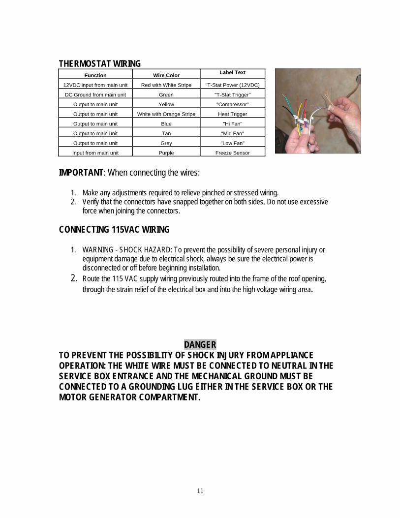
THERMOSTAT WIRING
Function Wire Color Label Text
12VDC input from main unit Red with White Stripe "T-Stat Power (12VDC)
DC Ground from main unit Green "T-Stat Trigger"
Output to main unit Yellow "Compressor"
Output to main unit White with Orange Stripe Heat Trigger
Output to main unit Blue "Hi Fan"
Output to main unit Tan "Mid Fan"
Output to main unit Grey "Low Fan"
Input from main unit Purple Freeze Sensor
IMPORTANT: When connecting the wires:
1. Make any adjustments required to relieve pinched or stressed wiring. 2. Verify that the connectors have snapped together on both sides. Do not use excessive
force when joining the connectors. CONNECTING 115VAC WIRING
1. WARNING - SHOCK HAZARD: To prevent the possibility of severe personal injury or equipment damage due to electrical shock, always be sure the electrical power is disconnected or off before beginning installation.
2. Route the 115 VAC supply wiring previously routed into the frame of the roof opening, through the strain relief of the electrical box and into the high voltage wiring area.
DANGER
TO PREVENT THE POSSIBILITY OF SHOCK INJURY FROM APPLIANCE OPERATION: THE WHITE WIRE MUST BE CONNECTED TO NEUTRAL IN THE SERVICE BOX ENTRANCE AND THE MECHANICAL GROUND MUST BE CONNECTED TO A GROUNDING LUG EITHER IN THE SERVICE BOX OR THE MOTOR GENERATOR COMPARTMENT.

12
ATTACH CEILING GRILL 1. Position the grill next to the interior frame and attach it with the 4 provided screws. 2. Install the filter on the air intake grill section. 3. Snap the intake grill section onto the main grille.
MAINTENANCE
1. AIR FILTER: Remove the return air filter (after every 30 days of use) located above the removable air
intake grill. Wash the filter with soap and warm water, let dry and then reinstall.
Note: Never run the air conditioner without returning air filter in place. This may plug the unit evaporator coil with dirt and may substantially affect the performance of the unit.
2. Air Return Grill: Clean panel and control panel with a soft cloth dampened with a mild detergent. Never
use furniture polish or harsh chemicals. 3. FAN MOTOR: Factory lubricated and requires no service under normal use. 4. FROST FORMATION ON COOLING COIL: Under certain conditions, frost may form on the evaporator coil. If this should occur,
inspect the filter and clean if dirty. Make sure air louvers are not obstructed. Air conditioners have a greater tendency to frost when the outside temperature is relatively low. This may be prevented by adjusting the thermostat control knob to a warmer setting (counter clockwise).

13
SERVICE If the unit does not operate:
1. If RV is connected to a generator, check to be sure generator is running and producing the proper power.
2. If RV is connected to shore power, check to be sure supply breaker is sized properly to run air conditioner load and it is plugged into power supply.
3. Check your fuse or circuit breaker to see if it is off. 4. After the above checks, call your local service center for further help. This unit must be
serviced by qualified service personnel only.
ASA TECHNICAL SERVICE 877-845-8750