INSTALLATION AND ASSEMBLY GUIDE - Fab-Tech, Inc
34
Catalog 04/20.3 INSTALLATION AND ASSEMBLY GUIDE Stainless Steel Corrosive Fume Exhaust System With PermaShield Fluoropolymer Barrier Coating
Transcript of INSTALLATION AND ASSEMBLY GUIDE - Fab-Tech, Inc

Catalog 04/20.3
INSTALLATION ANDASSEMBLY GUIDE
Stainless Steel CorrosiveFume Exhaust System WithPermaShield FluoropolymerBarrier Coating

GENERAL
CHARTS
FIELDMODIFICATIONS
DUCT ASSEMBLY
FIELD REPAIR
Introduction & General InformaitonPermaShield Duct Handling and Storage PermaShield Duct Mate to Other Duct Types
PermaShield Companion Ring Duct Installation: 4" (101.6) and LargerEZ Installation: 4" (101.6) thru 14" (355.6)
EZ Installation: 2" (50.8) and 3" (76.2)
PermaShield Duct Length Field Modifcation: 4" (101.6) thru 22" (558.8)
EZ Duct Length Field Modification: 2" (50.8) and 3" (76.2)
Saddle Tap Field Installation (PermaShield and EZ Duct)
Fab-Tech Flange Field Installation: 2" (50.8)
Male Nipple Field Installation Test Port (Lollipop) Field Installation: 3/8" (9.5), 3/4" (19.1) & 2" (50.8)
Fab-Tech Flange Assembly for Adapters
PermaShield Barrier Coating RepairSpark Test Protocol
Recommended Tooling
345
69
11
121416
19212427
3132
34
Damper Actuator Field Installation 28
Hot Tap Field Installation: 8" (203.2) thru 24" (609.6) 17
© COPYRIGHT 2020 FAB-TECH, INC. REV: 07/10/20 GUI002BD
2
FAB-TECH, Inc. / Tel: 802-655-8800 / Fax: 802-655-8804 / www.fabtechinc.com / [email protected]
2
METRIC EQUIVALENTS ARE SHOWN IN PARENTHESIS & ITALICS ( MILLIMETERS OR AS NOTED )
INSTALLATION & ASSEMBLY GUIDE
Contents

INTRODUCTION:
DAMAGE AND LOSS:
Fab-Tech's responsibility for damage, loss or delay on shipments ceases on acceptance of shipment by the freight line. Any claim for such damages, loss or delay must be filed with the freight line by the consignee. Consignee must inspect the shipment upon delivery and note any and all damages or discrepancies on the bill of lading. Consignee has 15 days after receipt to notify the freight line of damage and 9 months to file such claims.
PermaShield duct and fittings are manufactured witheither a bolted companion ring joining system or with asingle fastener band-style clamping system.
Introduction & General Info
© COPYRIGHT 2020 FAB-TECH, INC. REV: 07/10/20 GUI003BD
3
FAB-TECH, Inc. / Tel: 802-655-8800 / Fax: 802-655-8804 / www.fabtechinc.com / [email protected]
3
METRIC EQUIVALENTS ARE SHOWN IN PARENTHESIS & ITALICS ( MILLIMETERS OR AS NOTED )
INSTALLATION & ASSEMBLY GUIDE
In 1991, Fab-Tech Incorporated formed a unique partnership with a leading fluoropolymer manufacturer to to develop and manufacture a new generation of corrosive fume exhaust systems. The result of shared technologies was the creation of PermaShield products.PermaShield is a system that combines the structuralintegrity of stainless steel with the superior corrosion resistance of PermaShield Fluoropolymer Barrier Coating. PermaShield was crafted to meet the demanding safety standards of building and fire code officials as well as industry regulators and insurers.
PermaShield duct is designed and manufactured towithstand the effects of corrosive environments foundin most fume removal systems. The coating processrequires that very stringent manufacturing tolerancesbe maintained and that a high temperature, multi-bake process be used to achieve proper coating thickness and integrity.
PermaShield systems provide total ease of installationand maximum flexibility in the field. A significant featureof PermaShield contributing to the ease of installationis that our duct is FACTORY MUTUAL SYSTEMapproved for fume and smoke evacuation without theuse of sprinkler heads in the duct system. With properhandling and installation, you'll find the reliability ofstainless steel with PermaShield Fluoropolymer BarrierCoating and PTFE gaskets will provide long termbenefits and years of worry free productivity.
This guide is intended to aid you in the proper handling of our duct and to assist you in the assembly of the various types of joints necessary to maintain system integrity.
DUCT JOINING SYSTEMS:
COATING:
The PermaShield Fluoropolymer Barrier Coating is inspected at the factory. Sharp tools, operations thatrequire grinding and dirt must be kept away from theduct at all times. PermaShield products rely on coatedflange faces to provide a continuous corrosion barrier.Leave the packaging on the duct ends until just before installation.
DAMAGED COATING:
Extreme care must be taken throughout the entire handling and installation process to protect the coating During transportation or installation, the PermaShield coating may become scuffed and still be acceptable. A PermaShield fitting is deemed unacceptable whenthe coating has been damaged to the extent that thestainless steel has become visible and/or the duct failsat spark test (refer to the spark test procedure in thisguide). An unacceptable fitting can usually, but notalways, be repaired in the field. Repair instructionsand kits are available by contacting the factory. Repairinstructions are also included as part of this guide. Anydamaged fitting that cannot be field repaired must beeither factory repaired or discarded and replaced witha new PermaShield fitting.
WARRANTY:
Any field installations or post installation operations must be performed using factory authorized proceduresand accessories or the Fab-Tech warranty will be void.
Companion Ring Joining System Cast Rings: 4" (101.6) to 14" (355.6) dia. (standard) Angle Rings: 4" (101.6) to 120" (3048.0) dia.
Band-Style Joining System EZ: 2" (50.8) to 14" (355.6)
All joints use PermaShield Gasket 100% fully expandedPTFE gasket technology.
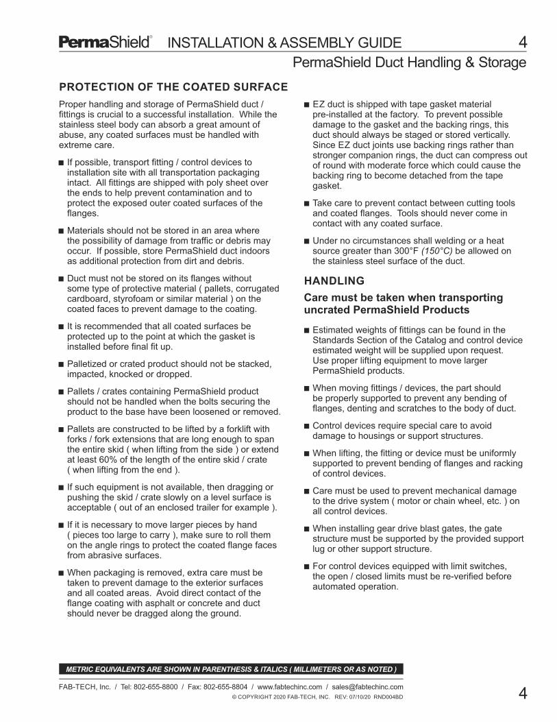
PROTECTION OF THE COATED SURFACE
If possible, transport fitting / control devices toinstallation site with all transportation packagingintact. All fittings are shipped with poly sheet overthe ends to help prevent contamination and toprotect the exposed outer coated surfaces of theflanges.
When packaging is removed, extra care must betaken to prevent damage to the exterior surfacesand all coated areas. Avoid direct contact of theflange coating with asphalt or concrete and ductshould never be dragged along the ground.
It is recommended that all coated surfaces beprotected up to the point at which the gasket isinstalled before final fit up.
Duct must not be stored on its flanges withoutsome type of protective material ( pallets, corrugatedcardboard, styrofoam or similar material ) on thecoated faces to prevent damage to the coating.
Palletized or crated product should not be stacked,impacted, knocked or dropped.
Pallets / crates containing PermaShield productshould not be handled when the bolts securing theproduct to the base have been loosened or removed.
Pallets are constructed to be lifted by a forklift withforks / fork extensions that are long enough to spanthe entire skid ( when lifting from the side ) or extendat least 60% of the length of the entire skid / crate( when lifting from the end ).
If such equipment is not available, then dragging orpushing the skid / crate slowly on a level surface isacceptable ( out of an enclosed trailer for example ).
HANDLING
Care must be taken when transportinguncrated PermaShield Products
Estimated weights of fittings can be found in theStandards Section of the Catalog and control deviceestimated weight will be supplied upon request.Use proper lifting equipment to move largerPermaShield products.
When moving fittings / devices, the part shouldbe properly supported to prevent any bending offlanges, denting and scratches to the body of duct.
Control devices require special care to avoiddamage to housings or support structures.
When lifting, the fitting or device must be uniformlysupported to prevent bending of flanges and rackingof control devices.
Care must be used to prevent mechanical damageto the drive system ( motor or chain wheel, etc. ) onall control devices.
When installing gear drive blast gates, the gatestructure must be supported by the provided supportlug or other support structure.
For control devices equipped with limit switches,the open / closed limits must be re-verified beforeautomated operation.
Materials should not be stored in an area wherethe possibility of damage from traffic or debris mayoccur. If possible, store PermaShield duct indoorsas additional protection from dirt and debris.
Take care to prevent contact between cutting toolsand coated flanges. Tools should never come incontact with any coated surface.
If it is necessary to move larger pieces by hand( pieces too large to carry ), make sure to roll themon the angle rings to protect the coated flange facesfrom abrasive surfaces.
Proper handling and storage of PermaShield duct /fittings is crucial to a successful installation. While thestainless steel body can absorb a great amount ofabuse, any coated surfaces must be handled withextreme care.
EZ duct is shipped with tape gasket materialpre-installed at the factory. To prevent possibledamage to the gasket and the backing rings, thisduct should always be staged or stored vertically.Since EZ duct joints use backing rings rather thanstronger companion rings, the duct can compress outof round with moderate force which could cause thebacking ring to become detached from the tapegasket.
Under no circumstances shall welding or a heatsource greater than 300°F (150°C) be allowed onthe stainless steel surface of the duct.
© COPYRIGHT 2020 FAB-TECH, INC. REV: 07/10/20 RND004BD
PermaShield Duct Handling & Storage
4
FAB-TECH, Inc. / Tel: 802-655-8800 / Fax: 802-655-8804 / www.fabtechinc.com / [email protected]
4
METRIC EQUIVALENTS ARE SHOWN IN PARENTHESIS & ITALICS ( MILLIMETERS OR AS NOTED )
INSTALLATION & ASSEMBLY GUIDE
The joining of PermaShield duct to duct materials otherthan Fab-Tech’s duct does not present any problems ifhandled properly.
Flanged Joints - All Materials:
In almost all cases a flange can be added to other products already used for corrosive fume exhaust systems. Wall thickness for various products to be joined may vary. The minimum information required by Fab-Tech to manufacture a matching joint is the inside diameter (I.D.) of the existing duct, and the inside diameter (I.D.) and outside diameter (O.D.) of the flange
®to which PSP is to be attached.
Flanges come in many different ratings and styles. When arranged by the buyer, Fab-Tech will make sure that bolt hole circles will match by providing a flange fabricated to the buyer’s specifications. (Fig. 1)
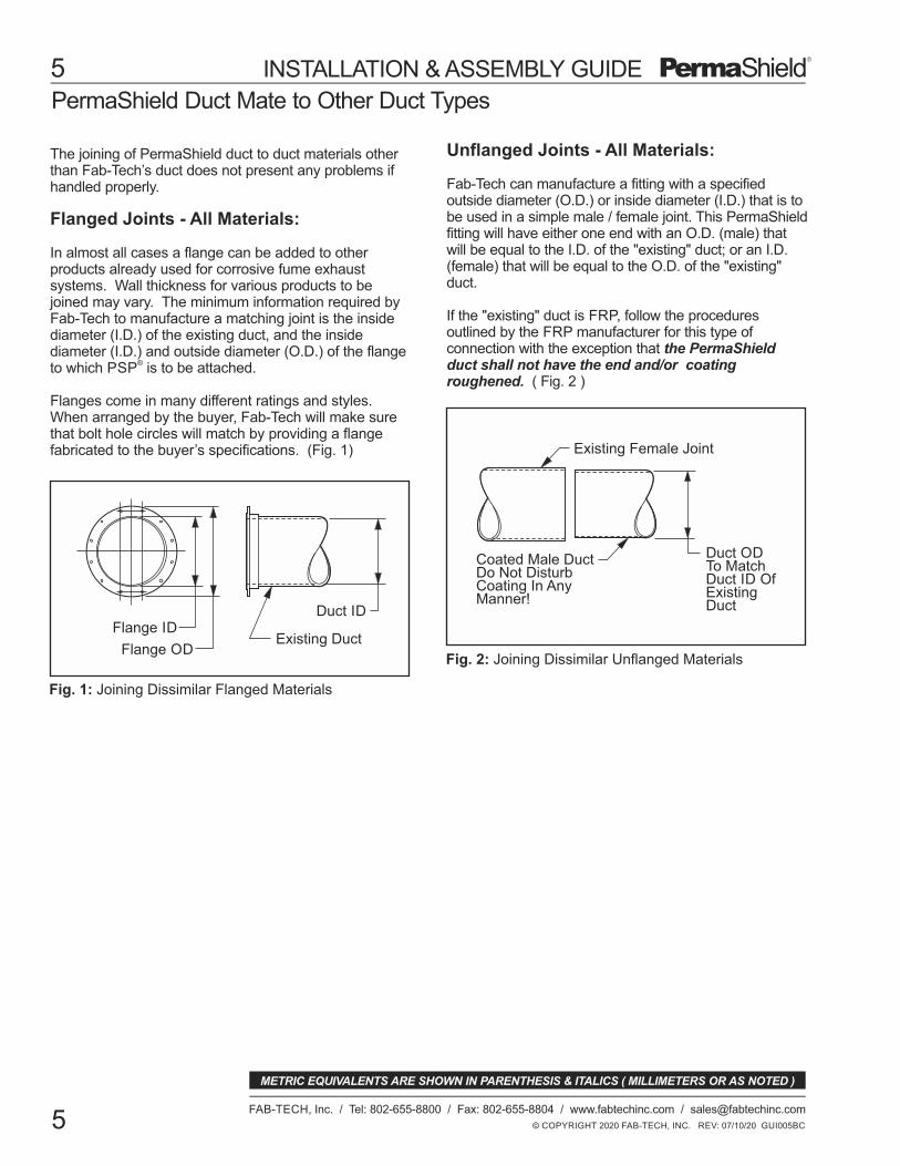
Unflanged Joints - All Materials:
Fab-Tech can manufacture a fitting with a specified outside diameter (O.D.) or inside diameter (I.D.) that is to be used in a simple male / female joint. This PermaShieldfitting will have either one end with an O.D. (male) thatwill be equal to the I.D. of the "existing" duct; or an I.D.(female) that will be equal to the O.D. of the "existing"duct.
If the "existing" duct is FRP, follow the proceduresoutlined by the FRP manufacturer for this type ofconnection with the exception that the PermaShieldduct shall not have the end and/or coatingroughened. ( Fig. 2 )
Fig. 2: Joining Dissimilar Unflanged Materials
Coated Male DuctDo Not DisturbCoating In AnyManner!
Existing Female Joint
Duct ODTo MatchDuct ID OfExistingDuct
Fig. 1: Joining Dissimilar Flanged Materials
Existing DuctFlange OD
Duct IDFlange ID
© COPYRIGHT 2020 FAB-TECH, INC. REV: 07/10/20 GUI005BC
5
FAB-TECH, Inc. / Tel: 802-655-8800 / Fax: 802-655-8804 / www.fabtechinc.com / [email protected]
5
PermaShield Duct Mate to Other Duct Types
METRIC EQUIVALENTS ARE SHOWN IN PARENTHESIS & ITALICS ( MILLIMETERS OR AS NOTED )
INSTALLATION & ASSEMBLY GUIDE

6
© COPYRIGHT 2020 FAB-TECH, INC. REV: 10/01/20 GUI006BD
FAB-TECH, Inc. / Tel: 802-655-8800 / Fax: 802-655-8804 / www.fabtechinc.com / [email protected]
6
METRIC EQUIVALENTS ARE SHOWN IN PARENTHESIS & ITALICS ( MILLIMETERS OR AS NOTED )
INSTALLATION & ASSEMBLY GUIDE
GENERAL:
Fixed Angle Ring
Duct Rolled Flange
Fig. 4: Floating angle rings 16" (406.4) - 30" (762.0)
Duct
Angle Ring
PlatedGrade 5Fasteners
Duct
PTFE Gasket
Angle Ring
PlatedGrade 5Fasteners
Stitch Welds
Fig. 5: Fixed angle rings 32" (812.8) - 120" (3048.0)
Cast RingStainless Steel
PTFE TapeGasket on Both Duct Flanges
Duct Rolled Flange
FloatingCast Ring
Fig. 3: Floating cast rings 4" (101.6) - 14" (355.6)
FloatingAngle Ring
Duct Rolled Flange
Duct
Duct
PlatedGrade 5Fasteners
Duct Duct
PermaShield Companion Ring Duct Installation 4" (101.6) and Larger
The 4" (101.6) and larger bolted companion ring systemhas unique installation requirements. Companion ringsare available in sizes from 4" (101.6) to 120" (3048.0).The minimum number of mounting holes for companionring connections is one hole for each 4" (101.6) of ductcircumference rounded up to the next higher number ofholes. See the catalog for specific ring information.The standard configuration for companion ring jointsvaries with duct size. They are as follows:
4" - 14" PermaShield Floating Rings:Duct from 4" (101.6) to 14" (355.6) diameter withcompanion ring joints are manufactured with rolled ductflanges and either floating black iron angle rings orfloating stainless steel cast rings. (Fig.3)
16" - 30" PermaShield Floating Rings:Duct from 16" (406.4) to 30" (762.0) diameter withcompanion ring joints are manufactured with rolled ductflanges and floating black iron or stainless steel anglerings. (Fig. 4)
32" - 120" PermaShield Fixed Rings:Duct in the 32" (812.8) to 120" (3048.0) diameter rangeare manufactured with rolled duct flanges and with theblack iron or stainless steel angle rings stitch welded tothe duct. The standard mounting hole locations forfixed angle rings straddle the vertical centerline unlessotherwise specified. (Fig. 5)
Gaskets: Standard PermaShield products are shippedwith all gaskets required to complete the joints. Thegasket material shall be form in place, fully expanded100% PTFE joint sealant. Use care when matchingthe gaskets. Substituting other gaskets will void thewarranty of the product. If a duct joint is disassembledfor any reason, the gasket has been disturbed andmust be replaced.
PTFE TapeGasket on Both Duct Flanges

GENERAL ( cont'd ):
PROCEDURE:
TOOLS REQUIRED:
Low torque air or electric wrenchSocket wrenchesBox wrenchesCutting toolCalibrated torque wrenchLint free cloth
PermaShield Companion Ring Duct Installation 4" (101.6) and Larger
© COPYRIGHT 2020 FAB-TECH, INC. REV: 12/20/20 GUI007BD
7
FAB-TECH, Inc. / Tel: 802-655-8800 / Fax: 802-655-8804 / www.fabtechinc.com / [email protected]
7
METRIC EQUIVALENTS ARE SHOWN IN PARENTHESIS & ITALICS ( MILLIMETERS OR AS NOTED )
The gaskets for companion ring duct joints come ineither loose bag lengths or on rolls. Please note thatdifferent types of gaskets are used for differentdiameters of PermaShield duct. (Fig. 6)
Fig. 6: Gasket size vs duct size
PTFE GASKETS* FOR RING JOINTS
Hardware: PermaShield products are shipped withall the hardware required to complete the joints. Thehardware shall be plated SAE Grade 5 fasteners. Usecare when matching the hardware. Substituting otherhardware will void the warranty of the product.Stainless steel fasteners are available on request butnot recommended. Please note bolt and torquespecifications vary with duct diameters. (Fig. 8)
4"-30" Ø
.01 X .75 TAPEP/N: GAS09
32"- 120" Ø& RECTANGULAR
1/4" x 3/16" ROPEP/N: GAS03
* ADHESIVE ON ONE SIDE
3/4" (19.05)
1/4"(6.35)
3/16"(4.76)
(101.6) - (762.0)Ø(812.8) - (3048.0)Ø HARDWARE FOR RING JOINTS
Fig. 8: Hardware size and torque specs vs duct size
1. Inspect Duct: All companion ring piecesare shipped with poly sheeting over the ends to helpprevent contamination and to protect the outer surfaceof the duct flange/ring. Carefully remove the polysheeting and inspect the interior coated surface andthe outer flange surfaces to insure the integrity of thesystem. Wipe away any dust and debris using a softlint free cloth. Do not, under any circumstances, installa piece of duct or fitting that has visible damage. Donot penetrate the coating for any reason except whenusing approved modification systems. Gasket tape ispre-installed on 4" (101.6) - 14" (355.6) duct.
2. Cut Flange Gasket: If pre-cut gasket lengths arenot provided for 32" (812.8) - 120" (3048.0) duct, cutrope gaskets to the correct length by wrapping thegasket around the duct and adding approximately 2"
GA
S0
1
GA
S0
2
GA
S0
3
GA
S0
9
GasketApplication
Product Size Inches (mm)
F**F*
F**F*
F**F*
F**F*
F
F
P
4 (101.6) - 10 (254.0)
12 (304.8) - 14 (355.6)
16 (406.4) - 24 (609.6)
26 (660.4) - 30 (762.0)
Wafer Damper
BlastgateActuated
End Cap
AMCA HVDDamper 16 (406.4) - 24 (609.6)
4 (101.6) - 10 (254.0)
12 (304.8) - 14 (355.6)
P - Apply gasket on PRODUCTF - Apply gasket on adjoining FLANGE* - Apply specified gasket on top of GAS09** - Factory applied gasket
P26+ (660.4)
GASKET APPLICATIONEXCEPTIONS
Fig. 7: Gasket application exceptions table
Note: Gasket Application Exceptions: Where standardgasket application is not possible; for example whenjoining an end cap to a standard duct flange in sizesbelow 32" (812.8) diameter there is no rolled flangeface to apply GAS09 gasket take to the cap.
In this instance, use the exceptions table to identifythe proper gasket application requirements. For thisexample; with a 14" (355.6) End Cap, apply GAS02gasket over the duct flange GAS09 prior to assemblyof the joint. (Fig. 7)
HVDDamper
Ultra SeriesDamper
INSTALLATION & ASSEMBLY GUIDE
DuctDia.
BoltSize
Torque in at least 3 stages
4"-10" 3/8"
Ft lb In lb Nm
35 420 48
Torque Specs: Grade 5 BoltMarkings:
(101.4-254.0) (9.53)
BoltMat'l
25 300 34
35 420 4825 300 34
3/8"(9.53)
**12-14"(304.8-355.6)
12"-120" 1/2" 65 780 88(304.8-3048.0) (12.7) 60 720 82
Gr.5*SS
Gr.5*SS
Gr.5*SS
STAINLESS STEEL HARDWARE REQUIRES APPLICATION OF ANTI-SEIZE LUBRICANT PRIOR TO ASSEMBLY. LOCKTITE LB771 OR EQUAL.
*REQUIRED FOR RINGS WITH 7/16" DIAMETER BOLT HOLES.**

PermaShield Companion Ring Duct Installation 4" (101.6) and LargerPROCEDURE (cont'd)
Apply gasketon the edge ofthe 3/8" (9.5)duct flange
Overlap endsbelow ringmounting hole
Fig. 10: Gasket installation for floating & fixed rings
© COPYRIGHT 2020 FAB-TECH, INC. REV: 12/22/20 GUI008BD
8
FAB-TECH, Inc. / Tel: 802-655-8800 / Fax: 802-655-8804 / www.fabtechinc.com / [email protected]
8
METRIC EQUIVALENTS ARE SHOWN IN PARENTHESIS & ITALICS ( MILLIMETERS OR AS NOTED )
INSTALLATION & ASSEMBLY GUIDE
Follow the Edgeof the Flange
Begin to Apply TapeTangent to the Duct Flange -Half on the Front Face andHalf on the Back Face ofthe Flange
1/2" (12.7) to 1" (25.4)Overlap with at Least80% of Front FlangeArea Covered with Tape
A
B
C
Fig. 9: Apply gasket for 4" (101.6) to 30" (762.0) duct
Duct Flange
4. Install Gasket 32" (812.8) - 120" (3048.0): To startinstallation, snap the gasket to peel the backing nearone end. Press the exposed adhesive side of thegasket firmly onto the angle ring below one of the holesat the top to the ring. Smoothly adhere the gasketaround the outside edge of the rolled duct flange.Overlap the end between 1" (25.4) and 2" (50.8) just
5. Install Hardware: Care must be taken not todisturb the gasket during duct joint positioning. Bringthe duct ends directly into place without shifting side toside and start a few bolts on opposite sides of the ring.
Check the alignment of the duct sections and whensatisfied, install the remaining fasteners. Each boltshould be installed with a flat washer beneath the bolthead and a flat washer against the ring on the nut endwith a lock washer between the nut and the flatwasher. Tighten all fasteners finger tight. (Fig. 11)
6. Torque Hardware: Hardware must be torqued inthe following sequence to evenly distribute pressure onthe gasket material and flange rings. Utilizing a lowtorque air/electric wrench or hand tools tighten theflange bolts in an alternating star pattern to 30% of thelisted torque value. The following steps shall be carriedout with a calibrated torque wrench in a circular patternaround the ring. Tighten the flange bolts to 60% of thelisted torque value. Adjust the torque wrench to 100%of the listed torque value and again tighten the bolts ina circular pattern. Passing by the first bolt in the torquesequence, verify that the first few bolts require noadditional twist to reach 100% torque value. If bolttwist is observed, continue in a circular sequence untilno further bolt twist occurs. Fab-Tech recommendedtorque values are listed in: (Fig. 8).
7. End of Procedure:
below the beginning bolt hole and continue up next tothe hole before trimming. Again, run a finger along thegasket to seat the adhesive. (Fig. 10)
3. Install Gasket 4" (101.6) - 30" (762.0): If the ductor fitting joint already has gasket tape applied, skip thisstep. Otherwise, the PTFE gasket is now appliedwhich comes as an adhesive backed tape. Slide thefloating ring a comfortable distance away from the ductrolled flange. Peel back the adhesive backing paper.Start (A) by firmly pressing the adhesive side of thetape to the rolled flange edge first at an angle tangentto the duct opening. Holding the end of the tape firmlyin place, continue applying the tape (B) by pulling andtacking it along the edge of the duct rolled flange.There will be enough width to the tape to be able topress the tape about equal amount onto the front andback sides of the rolled flange. To complete thisprocess (C), overlap the tape ends 1/2" (12.7) to 1"(25.4). Then firmly press the tape onto the rolledflange front and back to guarantee complete adhesion.Ensure about 80% of the front or outward flangesurface area is covered with sealant tape for bestmating joint. Slide the floating ring back against therolled flange for duct installation. (Fig. 9)
(50.8) to the length for overlap. Only one gasket isrequired for each joint.
Angle Ring
PlatedGrade 5Fasteners
Flat Washer Flat Washer
Lock WasherNut
Fig. 11: Angle ring hardware configuration

EZ Duct Installation: 4" (101.6) - 14" (355.6)
TOOLS REQUIRED:
7/16" (11.1) Box WrenchLow Torque Power Driver7/16" (11.1) Deep Socket DriverCalibrated Torque WrenchLint Free ClothLocking Pliers
FloatingEZ BackingRing
Duct Flange
Bolt Carrier
Fig. 12: 4" (101.6) - 14" (355.6) EZ configuration
EZ Clamp
Follow Edge ofBacking Ring
PTFE Gasket TapeBegin to Apply TapeTangent to Flange
1/2"(12.7) to 1"(25.4)OverlapAt Least 80% of FlangeArea Covered with Tape
A
B
C
Fig. 13: Apply gasket for 4"(101.6) - 14"(355.6) EZ duct
Floating EZ Backing Ring
Duct Flange
© COPYRIGHT 2020 FAB-TECH, INC. REV: 07/10/20 GUI009BC
9
FAB-TECH, Inc. / Tel: 802-655-8800 / Fax: 802-655-8804 / www.fabtechinc.com / [email protected]
9
METRIC EQUIVALENTS ARE SHOWN IN PARENTHESIS & ITALICS ( MILLIMETERS OR AS NOTED )
INSTALLATION & ASSEMBLY GUIDE
GENERAL:
PROCEDURE:
2. BRING FLANGES TOGETHER: Carefully bringtogether the two flanges to be joined. Duct supporthangers are the best method for aligning duct prior toinstallation. Secure this positioning using speciallocking pliers. (Fig. 14)
The EZ clamp system has unique installationrequirements. EZ duct is available in sizes from 2"(50.8) to 14" (355.6) and the standard configurationvaries with duct size. The standard configuration for 4"(101.6) to 14" (355.6) EZ joints is as follows:
4" (101.6) to 14" (355.6) EZ: Duct from 4" (101.6) to14" (355.6) EZ joints are manufactured with ductflanges, floating EZ backing rings and utilize singefastener band style clamps. The clamps shall providea minimum compression load to the gasket of 900 psi(6205 kPa). (Fig. 12)
Gasket: 4" (101.6) thru 14" (355.6) EZ duct andfittings are shipped with gasket tape applied at thefactory. The gasket material (PermaShield Gasket)shall be a form in place, fully expanded 100% PTFEjoint sealant. Each joint requires gasket tape on bothmating duct and/or fitting flanges. Substituting othergaskets will void the warranty of the product. If an EZjoint is disassembled for any reason, the gasket hasbeen disturbed and must be replaced.
1. INSTALL GASKET: If the duct or fitting jointalready has gasket tape applied, skip this step. Tobegin, slide the backing ring firmly against the flange.The PTFE gasket is now applied which comes as anadhesive backed tape. Start (A) by applying the tapeto the flange surface first at an angle tangent to theduct opening. Firmly press the tape onto the flange.There will be enough width to the tape so that you willbe able to press the tape onto the back side of thebacking ring. Holding the end of the tape firmly inplace, continue applying the tape (B) by pulling andtacking it along the edge of the backing ring. Tocomplete this process, (C) overlap the tape ends 1/2"(12.7) to 1" (25.4). Then go back and firmly press thetape onto the flange and backing ring to guaranteecomplete adhesion. The gasket tape has a secondaryfunction of holding the backing ring firmly against theflange. Make sure that at least 80% of the flangesurface area is covered with the sealant tape. (Fig. 13)

EZ Duct Installation: 4" (101.6) -14" (355.6)
Install Clampand TightenFastener toRecommendedTorque
DuctDia.
BoltSize
Torque Specifications:Torque in at least
3 stages
8",10",12",14" 5/16"
lb*ft lb*in kg*m
6.25 75 0.9
10 120 1.4
Fig. 15: Hardware size and torque specifications
2", 3", 4",6" 1/4"
Bolt Carrier
Fig. 14: Secure duct alignment with locking pliers
Duct
Adjusting Screw
LockingPliers
Duct
BackingRing With
Gasket
BackingRing With
Gasket
© COPYRIGHT 2020 FAB-TECH, INC. REV: 04/23/21 RND010BD
10
FAB-TECH, Inc. / Tel: 802-655-8800 / Fax: 802-655-8804 / www.fabtechinc.com / [email protected]
10
METRIC EQUIVALENTS ARE SHOWN IN PARENTHESIS & ITALICS ( MILLIMETERS OR AS NOTED )
INSTALLATION & ASSEMBLY GUIDE
PROCEDURE (cont'd):
3. INSTALL CLAMP: Using both hands, open theclamp and carefully slip the clamp onto the backingrings so that the "V" shaped groove in the clampaccepts each round surface of the backing rings.When the clamp is fully engaged around the entirecircumference, insert the clamp bolt through thecarrier and start the locknut on the bolt.
4. TIGHTEN CLAMP: Using a 7/16" (11.1) wrench orlow torque power drive, tighten the clamp by tighteningthe nut on the clamp fastener until the clamp just startsto grip the gasket. Although this method of joining ductis self aligning, visually inspect the joint to ensureproper alignment of the flanges and proper seating ofthe backing rings in the clamp. Remove the lockingpliers. Tighten the clamp until resistance to furthertightening is felt.
5. TORQUE BOLT: When satisfied with the alignment,tighten the clamp bolt to the specified torque with acalibrated torque wrench. (Fig. 15)
6. END OF PROCEDURE:
(7.9)
(6.35)
(203.2, 254.0,304.8, 355.6)
(50.8, 76.2,101.6, 152.4)
EZ Duct Installation: 2" (50.8) and 3" (76.2)
TOOLS REQUIRED:
7/16" (11.1) Box WrenchLow Torque Power Driver7/16" (11.1) Deep Socket DriverCalibrated Torque WrenchLint Free Cloth
5. End of Procedure:
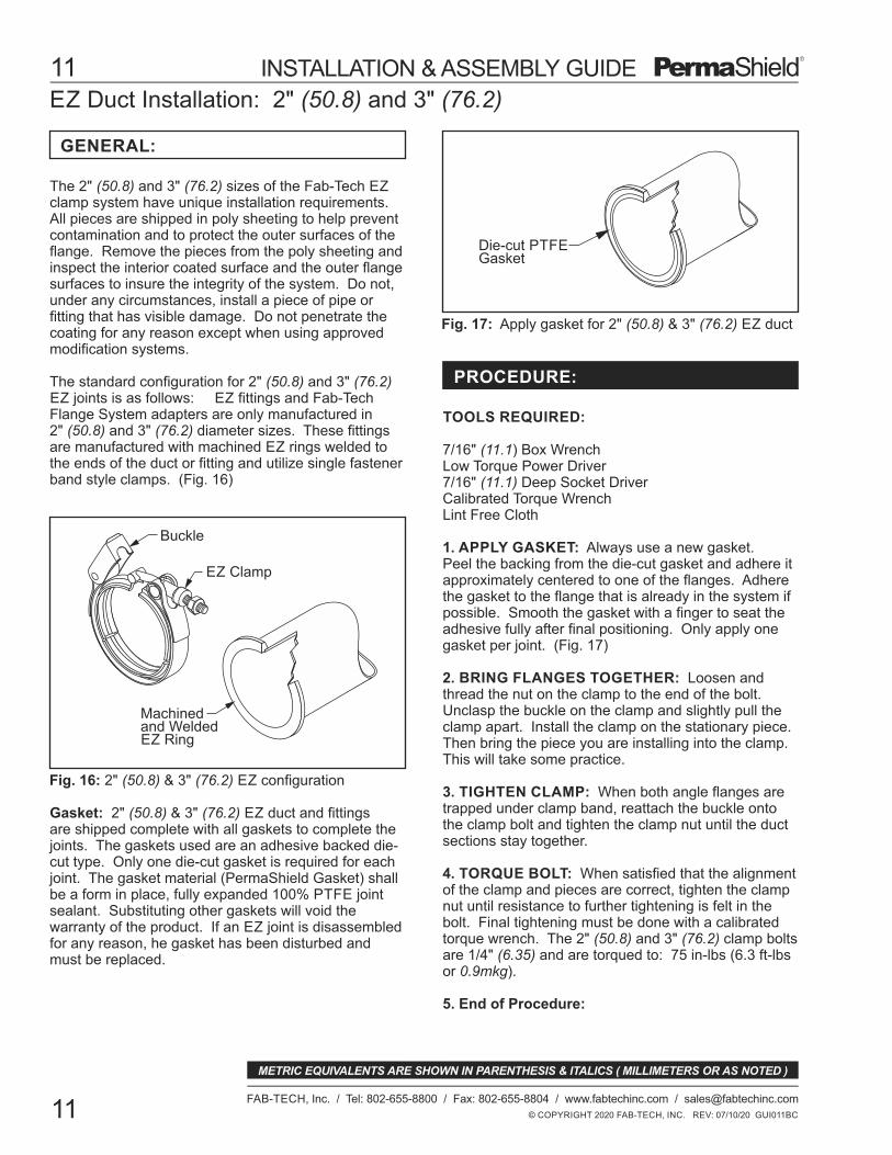
Die-cut PTFEGasket
Fig. 17: Apply gasket for 2" (50.8) & 3" (76.2) EZ duct
Machinedand WeldedEZ Ring
EZ Clamp
Buckle
Fig. 16: 2" (50.8) & 3" (76.2) EZ configuration
© COPYRIGHT 2020 FAB-TECH, INC. REV: 07/10/20 GUI011BC
11
FAB-TECH, Inc. / Tel: 802-655-8800 / Fax: 802-655-8804 / www.fabtechinc.com / [email protected]
11
METRIC EQUIVALENTS ARE SHOWN IN PARENTHESIS & ITALICS ( MILLIMETERS OR AS NOTED )
INSTALLATION & ASSEMBLY GUIDE
GENERAL:
PROCEDURE:
1. APPLY GASKET: Always use a new gasket.Peel the backing from the die-cut gasket and adhere itapproximately centered to one of the flanges. Adherethe gasket to the flange that is already in the system ifpossible. Smooth the gasket with a finger to seat theadhesive fully after final positioning. Only apply onegasket per joint. (Fig. 17)
2. BRING FLANGES TOGETHER: Loosen andthread the nut on the clamp to the end of the bolt.Unclasp the buckle on the clamp and slightly pull theclamp apart. Install the clamp on the stationary piece.Then bring the piece you are installing into the clamp.This will take some practice.
3. TIGHTEN CLAMP: When both angle flanges aretrapped under clamp band, reattach the buckle ontothe clamp bolt and tighten the clamp nut until the ductsections stay together.
4. TORQUE BOLT: When satisfied that the alignmentof the clamp and pieces are correct, tighten the clampnut until resistance to further tightening is felt in thebolt. Final tightening must be done with a calibratedtorque wrench. The 2" (50.8) and 3" (76.2) clamp boltsare 1/4" (6.35) and are torqued to: 75 in-lbs (6.3 ft-lbsor 0.9mkg).
Gasket: 2" (50.8) & 3" (76.2) EZ duct and fittingsare shipped complete with all gaskets to complete thejoints. The gaskets used are an adhesive backed die-cut type. Only one die-cut gasket is required for eachjoint. The gasket material (PermaShield Gasket) shallbe a form in place, fully expanded 100% PTFE jointsealant. Substituting other gaskets will void thewarranty of the product. If an EZ joint is disassembledfor any reason, he gasket has been disturbed andmust be replaced.
The 2" (50.8) and 3" (76.2) sizes of the Fab-Tech EZclamp system have unique installation requirements.All pieces are shipped in poly sheeting to help preventcontamination and to protect the outer surfaces of theflange. Remove the pieces from the poly sheeting andinspect the interior coated surface and the outer flangesurfaces to insure the integrity of the system. Do not,under any circumstances, install a piece of pipe orfitting that has visible damage. Do not penetrate thecoating for any reason except when using approvedmodification systems.
The standard configuration for 2" (50.8) and 3" (76.2)EZ joints is as follows: EZ fittings and Fab-TechFlange System adapters are only manufactured in2" (50.8) and 3" (76.2) diameter sizes. These fittingsare manufactured with machined EZ rings welded tothe ends of the duct or fitting and utilize single fastenerband style clamps. (Fig. 16)

PermaShield Duct Length Field Modification: 4" (101.6) thru 22" (558.8)
TOOLS REQUIRED:
Fig. 18: Measure for modification
Fig. 19: Flanging Tool Setup
PEXTO
RollsBackstop
Upper Roller Crank
LowerRollerCrank
© COPYRIGHT 2020 FAB-TECH, INC. REV: 07/10/20 GUI012BC
12
FAB-TECH, Inc. / Tel: 802-655-8800 / Fax: 802-655-8804 / www.fabtechinc.com / [email protected]
12
METRIC EQUIVALENTS ARE SHOWN IN PARENTHESIS & ITALICS ( MILLIMETERS OR AS NOTED )
INSTALLATION & ASSEMBLY GUIDE
GENERAL:
PROCEDURE:
PermaShield duct can be shortened in the field. Thiscan be done to duct sections that are constructed of18GA (1.27) material or lighter. For companion ringduct, the range of sizes able to be shortened is from4" (101.6) to 22" (558.8). For EZ duct, the range ofsizes able to be shortened is from 4" (101.6) to 14"(355.6).
Marking PenFlexible RulerDrillCenter PunchDouble Cut Power ShearFlat FileFlanging Tool - Pexto model 6221/8" Drill BitStep Drill
1. MEASURE THE DUCT: Measure the installationfor the desired section length. (Fig. 18) Transfer thismeasurement to the duct section to be shortened. Add3/8" (9.5) to the measured length to allow for the flangeheight. Mark this measurement in several placesaround the duct circumference. Connect these marksusing a marking pen and flexible ruler.
2. SLIDE RING: For companion ring duct, carefullyslide the floating ring back along the duct beyond thecutting guide line. For EZ duct, carefully remove thegasket tape from the backing ring and also carefuuly
3. CUT DUCT: Drill a 3/8" (9.5) to 1/2" (12.7) hole justtangent to the scrap side of the cutting line. First, markthe location for the starter hole and center punch thelocation. Drill a starter hole using the 1/8" (3.2) drill.Enlarge this pilot hole in small steps using a step drill.Proceed slowly so that a minimum of heat is generated,as excessive heat can damage the coating. Insert apower shear, double cut recommended, at this holeand cut as accurately as possible on the scrap side ofthe line.
4. SMOOTH EDGES: Using a file, remove all sharpedges from the cut. Be careful that the end of the filedoes not damage the coating.
5. FLANGE TOOL SETUP: Assemble tool per themanufacturer's directions. (Fig. 19) The rolls must beclean, undamaged and burr free. Any metal filings,chips, dirt or abrasive material will damage the coating.Roll flanges in a clean work site that is not near anygrinding or welding operations. The gold colored rollsare custom rolls supplied by Fab-Tech. These rolls areground smooth and hardened to provide an accurateand burr free surface to work the coating during theflanging process.
the backing ring back along the duct beyond the cuttingguide line. This is to ensure that the companion ring orbacking ring doesn't interfere with the cutting and flaringoperation.

PermaShield Duct Length Field Modification: 4" (101.6) thru 22" (558.8)
Fig. 20: Flange Height Dimensions & Tolerances
Fig. 21: EZ Backing Ring Position
Flange Flange
Angle Ring3/8"(9.5) ± 1/16"(1.6)
EZ
No! Yes!
3/8"(9.5) +0-1/16 (1.6)
© COPYRIGHT 2020 FAB-TECH, INC. REV: 07/10/20 GUI013BC
13
FAB-TECH, Inc. / Tel: 802-655-8800 / Fax: 802-655-8804 / www.fabtechinc.com / [email protected]
13
METRIC EQUIVALENTS ARE SHOWN IN PARENTHESIS & ITALICS ( MILLIMETERS OR AS NOTED )
INSTALLATION & ASSEMBLY GUIDE
10. END OF PROCEDURE:
8. SPARK TESTING: Follow the appropriate sparktest protocol as noted in this guide.
9. INSTALL GASKET: For PermaShield duct, slidethe companion ring up against the new flange. Applygasket as required, only one gasket is required perjoint for companion ring joints. For EZ duct, slide thebacking ring up against the new flange. If installing anew backing ring, make sure that the round face of thering is positioned away from the duct flange. (Fig. 21)Once the EZ backing ring is in place, apply PTFEgasket as noted in this guide. The shortened ductsection is now ready to be installed.
PROCEDURE (cont'd):
7. FLANGE DUCT END: Place the cut end of theduct on the lower roller and slide the duct up againstthe backstop. Lower the upper roller with the smallercrank located on the top of the tool. Tighten the rolls toslightly pinch the duct between the rollers. Do not overtighten the rollers as this can damage the coating.Crank the large handle with one hand while steadyingthe duct section with the other hand to flare the ductwall. Slight upward pressure on the duct whilecranking will begin to crease the metal at the face ofthe upper roller. Continue around the duct slowly untilthe flange is turned to an appropriate degree wherethe balance can be completed with a clean plastic,rawhide or rubber mallet. Place a clean cloth over theflange before using the mallet to provide addedprotection for the coating. Loosen the rollers andremove the duct from the tool.
6. SET FLANGE HEIGHT: Once the backstop isinstalled, it should be adjusted to slightly more than3/8" (9.5) depth from the roll faces and locked in place.This dimension sets the height of the flange. Werecommend that you experiment with some scrappieces of duct to make sure the setting is producingthe flange height desired. Fab-Tech generally uses a3/8" (9.5) flange height. The tolerance for this flangeheight varies for the EZ and PermsShield companionring joint types. If the piece will be used with a ringflange, the tolerance is ±1/16" (1.6). If the joint has aclamp, the flange should not be higher than 3/8" (9.5)but it is allowed to be 1/16" (1.6) less, or 5/16" (7.9)high. This tolerance is important to the function of theclamped system. A quick check for correct flangeheight for clamped joints can be done by using analuminum backing ring as a checking gage. (Fig. 20)
TOOLS REQUIRED:
Ridgid Pipe Cutter - Size 1" (25.4) - 3" (76.2)Rawhide Mallet or "Dead Blow" HammerFab-Tech Part #D0700, Pressing Wheel AdapterVice or Pipe StandFlat FileLint Free Cloth
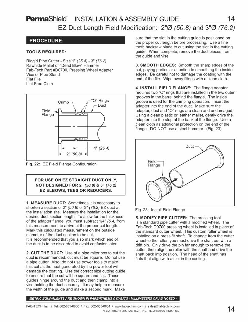
Duct"O" Rings
FieldFlange
2" (50.8)
1" (25.4)
Fig. 22: EZ Field Flange Configuration
Crimp
FieldFlange
Duct
Fig. 23: Install Field Flange
© COPYRIGHT 2020 FAB-TECH, INC. REV: 07/10/20 RND014BC
14
FAB-TECH, Inc. / Tel: 802-655-8800 / Fax: 802-655-8804 / www.fabtechinc.com / [email protected]
14
METRIC EQUIVALENTS ARE SHOWN IN PARENTHESIS & ITALICS ( MILLIMETERS OR AS NOTED )
INSTALLATION & ASSEMBLY GUIDE
FOR USE ON EZ STRAIGHT DUCT ONLY,
NOT DESIGNED FOR 2" (50.8) & 3" (76.2)
EZ ELBOWS, TEES OR REDUCERS.
PROCEDURE:
EZ Duct Length Field Modification: 2"Ø (50.8) and 3"Ø (76.2)
5. MODIFY PIPE CUTTER: The pressing toolis a standard pipe cutter with a modified wheel. TheFab-Tech D0700 pressing wheel is installed in place ofthe standard cutter wheel. This custom roller wheel isinstalled on a press fit shaft. To change from the cutterwheel to the roller, you must drive the shaft out with adrift pin. Only drive the pin far enough to remove thecutter, then align the roller with the shaft and drive theshaft back into position. The head of the shaft hasflats that align with a slot in the casting.
1. MEASURE DUCT: Sometimes it is necessary toshorten a section of 2" (50.8) or 3" (76.2) EZ duct atthe installation site. Measure the installation for thedesired duct section length. To allow for the thicknessof the adapter flange, you must subtract 1/4" (6.4) fromthis measurement to arrive at the proper cut length.Mark this calculated measurement on the outsidediameter of the duct section to be cut.It is recommended that you also mark which end ofthe duct is to be discarded to avoid confusion later.
2. CUT THE DUCT: Use of a pipe miter box to cut theduct is recommended, cut must be square. Do not usea pipe cutter. Also, do not use power tools to makethis cut as the heat generated by the power tool willdamage the coating. Use the correct size cutting guideto ensure that the cut will be square and flat. Theseguides hinge around the duct and then clamp into avise holding the duct securely. It may help to measurethe width of the guide and make a second mark. Make
sure that the slot in the cutting guide is positioned onthe proper cut length before processing. Use a finetooth hacksaw blade to cut using the slot in the cuttingguide. When complete, remove the duct pieces fromthe guide and vise.
3. SMOOTH EDGES: Smooth the sharp edges of thecut, paying particular attention to smoothing the insideedges. Be careful not to damage the coating with theend of the file. Wipe away filings with a clean cloth.
4. INSTALL FIELD FLANGE: The flange adapterrequires two "O" rings that are installed in the two outergrooves in the barrel behind the flange. The insidegroove is used for the crimping operation. Insert theadapter into the end of the duct. Make sure theadapter, duct and "O" rings are clean and undamaged.Using a clean plastic or leather mallet, gently drive theadapter into the stop at the back of the flange. Use aclean cloth as additional protection on the end of theflange. DO NOT use a steel hammer. (Fig. 23)

Fig. 24: EZ Field Flange Crimp
FieldFlange
Duct
Crimp
© COPYRIGHT 2020 FAB-TECH, INC. REV: 07/10/20 GUI015BC
15
FAB-TECH, Inc. / Tel: 802-655-8800 / Fax: 802-655-8804 / www.fabtechinc.com / [email protected]
15
METRIC EQUIVALENTS ARE SHOWN IN PARENTHESIS & ITALICS ( MILLIMETERS OR AS NOTED )
INSTALLATION & ASSEMBLY GUIDE
PROCEDURE (cont'd):
7. CRIMP DUCT: Then rotate the tool around thepipe making a shallow groove. The first pass shouldbe very slight in depth. This operation is to make surethat the roller is following a straight line around thepipe. When a complete crimp impression is made,tighten again with the screw and crank to deepen thecrimp. Use multiple passes to form a bead 1/32" (.79)deep minimum. When the crimp is complete, theclamp screw will get very difficult to tighten. Whencomplete, loosen the clamp screw and remove thetool. (Fig. 24)
8. END OF PROCEDURE:
EZ Duct Length Field Modification: 2"Ø (50.8) and 3"Ø (76.2)
6. CRIMP DUCT: Measure back from the cut end ofthe pipe at 1" (25.4). Make several marks around theduct at this measurement. Open the pipe cutter so thatit fits over the pipe. Align the custom roller with themarks on the duct section. Tighten the pipe cutterusing the large clamp screw handle until it just makesan impression in the metal at the tip of the roller.

HostDuct
Studs and Nuts
Exterior SaddleFrame
Interior Saddlewith Tap
PTFE Gasket
FAB-TECH FlangeSaddle Tap
Fig. 25: Saddle Tap Configuration
Fig. 26: Interior and Exterior Saddles
Fig. 27: PermaShield and EZ Saddle Taps
PermaShieldSaddle Tap
Exterior SaddleInterior Saddle
GasketCenteringStud
Saddle Tap Field Installation
© COPYRIGHT 2020 FAB-TECH, INC. REV: 07/10/20 RND016BC
16
FAB-TECH, Inc. / Tel: 802-655-8800 / Fax: 802-655-8804 / www.fabtechinc.com / [email protected]
16
METRIC EQUIVALENTS ARE SHOWN IN PARENTHESIS & ITALICS ( MILLIMETERS OR AS NOTED )
INSTALLATION & ASSEMBLY GUIDE
PROCEDURE:
1. CUT OPENING: Trace the template which isprovided with the saddle tap onto the host duct. Use acenter punch to mark the pilot holes which are drilledon each corner of the template. Drill larger holes ineach corner to accommodate the power shear. Cutopening in the host duct and carefully file the edges ofthe cut. If it is necessary to preserve the air pressurein the system, cut a thin sheet of galvanized steel 2"(50.8) larger than the dimension of the template andplace over the hole.
2. INSTALL INTERIOR SADDLE: Apply PTFEgasket to the outside edge of the interior saddle, asshown. Slip the interior saddle carefully into theopening. With the saddle in place, insert studs fingertight into the two horizontal center holes. (Fig. 26)
3. INSTALL EXTERIOR FRAME: Set the exteriorframe over the tap, locating the slots over the twoexposed centering studs. Place flat washer, lockwasher and nut onto each center stud, lightly tighten.This will position the saddle tap temporarily in place.
It is recommended that two persons are available to dothis installation, at the discretion of the project manager,depending on the size of the fitting and the location ofthe branch line at the host duct. Check that all requiredmaterial is available at the work location.
TOOLS REQUIRED:
Center PunchMarking PenPower ShearCalibrated Torque WrenchFlat FileLint Free Cloth
4. POSITION TAP: Install studs along the bottomhorizontal edge of the interior saddle. Finger tighten.Reposition the tap by gently pulling down on the tapuntil the bottom studs contact the raw edge of the hostduct opening. Now tighten the two horizontal centernuts to draw the saddle halves together.
5. INSTALL HARDWARE: Install studs in allremaining holes of the interior saddle. Finger tighten.Visually inspect that the saddle tap is in position andthat the gasket can make full contact with the interiorof the host duct. Place flat washer, lock washer andnut onto each of the studs, lightly tighten.
6. TORQUE NUTS: Using a calibrated torque wrench,tighten the two center horizontal nuts to recommendedtorque specifications (8 ft-lbs (10.8 Nm) minimum for5/16" (7.9) bolts, 15 ft-lbs (20.3 Nm) minimum for 3/8"(9.5) bolts, torque in at least 3 stages until specifiedtorque is reached). Continue tightening all the othernuts to recommended specifications, moving evenlyaway from the center nuts to prevent distortion of thesaddle against the host duct. On larger duct, tightenfrom the center of all four sides of the saddle. Leavethe corner studs as the last ones to tighten. The saddletap is now ready to use.
7. END OF PROCEDURE:

Fig. 28: Hot Tap - Section Through Duct
Hot Tap Field Installation: 8" (203.2) - 24" (609.6)
HOST DUCT I.D., PRESSURECLASS & MATERIAL TYPE
( REQUIRED INFORMATION )
Tap Diameter
6" (152.4)STD
Host Duct
Anchor Bolts
Backing Ring
End Cap
FluoropolymerCoated ThreadedCaps Welded toBacking Ring
PTFE Gasket
© COPYRIGHT 2020 FAB-TECH, INC. REV: 07/10/20 GUI017BC
17
FAB-TECH, Inc. / Tel: 802-655-8800 / Fax: 802-655-8804 / www.fabtechinc.com / [email protected]
17
METRIC EQUIVALENTS ARE SHOWN IN PARENTHESIS & ITALICS ( MILLIMETERS OR AS NOTED )
INSTALLATION & ASSEMBLY GUIDE
TOOLS REQUIRED:
GENERAL:
PROCEDURE (cont'd):
4. CUT TAP OPENING: Use a metal cutting jig sawto cut the hot tap opening. Slide the pressure plateover the hot tap hole and under the hot tap cutout as itis being cut to maintain system pressure.
5. POSITION GLOVE BOX: Using the hot taphorizontal centerline markings from Step 2, position theglove box on the duct over the hot tap pressure plateand hold in place with duct tape.
6. POSITION TAP BACKING RING: Lift the plexi-glass viewing window and place the hot tap backingring and the alignment bolt inside the glove box andclose the viewing window. Insert hands into the glovesand hold the backing ring. Have a second person slidethe pressure plate out of the way. Position the backingring inside the duct to align with the curvature of theduct.
The field Installed 4" (101.6) to 24" (609.6) diameterhot tap is unique in that it allows for a PermaShield tapfitting to be installed in a live duct system ranging insize from 12" (304.8) diameter and larger without costlyshutdown of the system and disruption in production.See the tap to host duct matrix below to find the correctsize tap for your system.
3. PUNCH: Center punch and drill the alignment bolthole and a starter hole just above the tab for cutting thehot tap opening.
2. TRACE TEMPLATE: Trace the hot tap hole andalignment bolt hole onto the duct using a permanentmarker. Also mark the line the approximate horizontalcenterline position of the hot tap on the duct.
1. POSITION TAP TEMPLATE: Place the hot taptemplate on the duct at the desired location. Positiontemplate such that the tab and alignment bolt hole arelocated at the bottom of the desired location.
Metal Cutting Jig Saw with Carbide Saw BladeElectric or Pneumatic Drill - Drill bit 5/16" (7.9)Permanent MarkerCenter PunchDuct TapeAllen WrenchGlove Box (required) with Pressure PlateTorque Wrench and Socket
Hot Tap Field Installation: 8" (203.2) - 24" (609.6)
Fig. 29: Hot tap basic assembly.
Backing Ring ( inside duct )
Hot Tap
Anchor Bolts
View the complete installation video that these screen shots were taken from at:www.fabtechinc.com/literature
© COPYRIGHT 2020 FAB-TECH, INC. REV: 07/10/20 RND018BC
18
FAB-TECH, Inc. / Tel: 802-655-8800 / Fax: 802-655-8804 / www.fabtechinc.com / [email protected]
18
METRIC EQUIVALENTS ARE SHOWN IN PARENTHESIS & ITALICS ( MILLIMETERS OR AS NOTED )
INSTALLATION & ASSEMBLY GUIDE
PROCEDURE (cont'd):
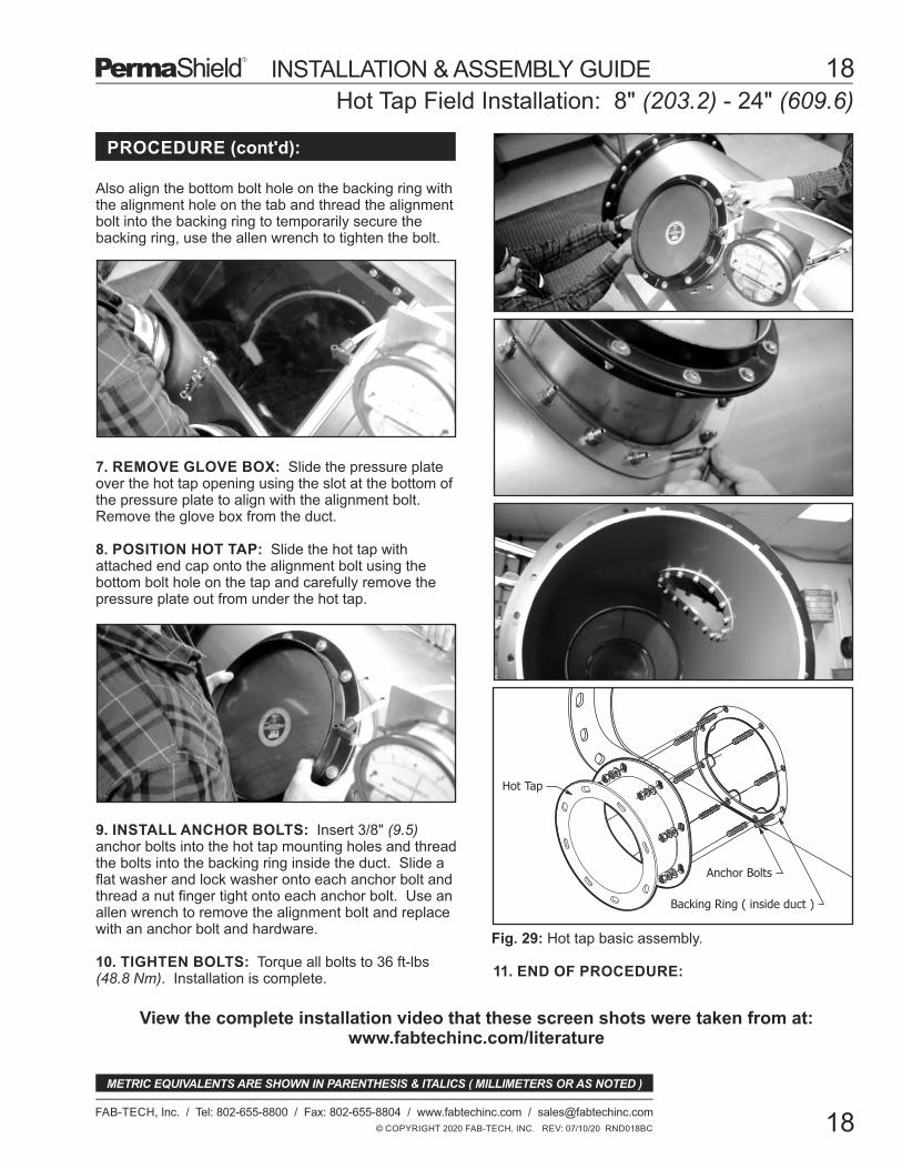
7. REMOVE GLOVE BOX: Slide the pressure plateover the hot tap opening using the slot at the bottom ofthe pressure plate to align with the alignment bolt.Remove the glove box from the duct.
8. POSITION HOT TAP: Slide the hot tap withattached end cap onto the alignment bolt using thebottom bolt hole on the tap and carefully remove thepressure plate out from under the hot tap.
9. INSTALL ANCHOR BOLTS: Insert 3/8" (9.5)anchor bolts into the hot tap mounting holes and threadthe bolts into the backing ring inside the duct. Slide aflat washer and lock washer onto each anchor bolt andthread a nut finger tight onto each anchor bolt. Use anallen wrench to remove the alignment bolt and replacewith an anchor bolt and hardware.
10. TIGHTEN BOLTS: Torque all bolts to 36 ft-lbs(48.8 Nm). Installation is complete. 11. END OF PROCEDURE:
Also align the bottom bolt hole on the backing ring withthe alignment hole on the tab and thread the alignmentbolt into the backing ring to temporarily secure thebacking ring, use the allen wrench to tighten the bolt.
TOOLS REQUIRED:
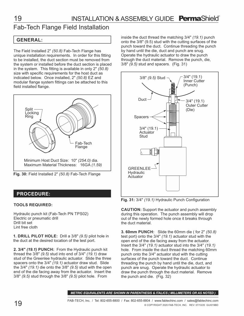
3/4" (19.1)Outer Cutter(Die)
GREENLEEHydraulicActuator
Duct
3/4" (19.1)Inner Cutter(Punch)
3/8" (9.5) Stud
Spacers
3/4" (19.1)ActuatorStud
Fig. 31: 3/4" (19.1) Hydraulic Punch Configuration
SplitLockingRing
Fab-TechFlange
Minimum Host Duct Size: 10" (254.0) dia.Maximum Material Thickness: 16GA (1.59)
Fig. 30: Field Installed 2" (50.8) Fab-Tech Flange
Fab-Tech Flange Field Installation
© COPYRIGHT 2020 FAB-TECH, INC. REV: 07/10/20 GUI019BD
19
FAB-TECH, Inc. / Tel: 802-655-8800 / Fax: 802-655-8804 / www.fabtechinc.com / [email protected]
19
METRIC EQUIVALENTS ARE SHOWN IN PARENTHESIS & ITALICS ( MILLIMETERS OR AS NOTED )
INSTALLATION & ASSEMBLY GUIDE
GENERAL:
PROCEDURE:
CAUTION: Support the actuator and punch assemblyduring this operation. The punch assembly will dropout of the newly formed hole once it breaks throughthe duct material.
3. 60mm PUNCH: Slide the 60mm die ( for 2" (50.8)test port) onto the 3/4" (19.1) actuator stud with theopen end of the die facing away from the actuator.Insert the 3/4" (19.1) actuator stud into the 3/4" (19.1)hole. From inside the duct thread the matching 60mmpunch onto the 3/4" actuator stud with the cuttingsurfaces of the punch toward the duct. Continuethreading the punch by hand until the die, duct, andpunch are snug. Operate the hydraulic actuator todraw the punch through the duct material. Removethe punch and die. (Fig. 32)
The Field Installed 2" (50.8) Fab-Tech Flange hasunique installation requirements. In order for this fittingto be installed, the duct section must be removed fromthe system or installed before the duct section is placedin the system. This fitting is available in only 2" (50.8)size with specific requirements for the host duct asindicated below. Once installed, 2" (50.8) EZ andmodular flange system fittings can be attached to thisfield installed flange.
Hydraulic punch kit (Fab-Tech PN TPS02)Electric or pneumatic drillDrill bit setLint free cloth
1. DRILL PILOT HOLE: Drill a 3/8" (9.5) pilot hole inthe duct at the desired location of the test port.
inside the duct thread the matching 3/4" (19.1) punchonto the 3/8" (9.5) stud with the cutting surfaces of thepunch toward the duct. Continue threading the punchby hand until the die, duct and punch are snug.Operate the hydraulic actuator to draw the punchthrough the duct material. Remove the punch, die,3/8" (9.5) stud and spacers. (Fig. 31)
2. 3/4" (19.1) PUNCH: From the Hydraulic punch kitthread the 3/8" (9.5) stud into end of 3/4" (19.1) drawstud of the Greenlee hydraulic actuator. Slide the threespacers onto the 3/4" (19.1) actuator draw stud. Slidethe 3/4" (19.1) die onto the 3/8" (9.5) stud with the openend of the die facing away from the actuator. Insert the3/8" (9.5) stud through the 3/8" (9.5) pilot hole. From

Duct
3/4" (19.1)Actuator Stud
Inner Cutter( Punch )
OuterCutter(Die)
Fig. 34: Field Installed 2" FT Flange Configuration
Fig. 32: 60mm Hydraulic Punch Configuration
Fig. 33: 60mm Swage Configuration
InvertedPunch
Duct
OuterSwage
InnerSwage
LockingRing
DuctGasket
Fab-Tech Flange Field Installation
© COPYRIGHT 2020 FAB-TECH, INC. REV: 07/10/20 RND020BE
20
FAB-TECH, Inc. / Tel: 802-655-8800 / Fax: 802-655-8804 / www.fabtechinc.com / [email protected]
20
METRIC EQUIVALENTS ARE SHOWN IN PARENTHESIS & ITALICS ( MILLIMETERS OR AS NOTED )
INSTALLATION & ASSEMBLY GUIDE
PROCEDURE (cont'd):
3/4" (19.1)Actuator Stud
5. INSTALL FAB-TECH FLANGE: Remove thebacking and apply die-cut PermaShield Gasket to theinside flange of the fitting. Place the fitting in theswaged hole from inside the duct so that the gasketforms a seal between the inside flange and the duct.Thread the matching split locking ring onto the fittingand tighten until snug. Using the appropriate sizewrench on the locking ring and the flats on the fitting,tighten the locking ring until there is resistance tofurther tightening. Installation is complete. (Fig. 34)
6. END OF PROCEDURE:
4. SWAGE HOLE: Slide the 60mm outer swage toolonto the 3/4" (19.1) actuator stud. Insert the actuatorstud and outer swage tool into the 60mm hole. Frominside the duct slide the matching inner swage toolonto the actuator stud. Invert and thread any one ofthe three punches onto the actuator stud (cuttingsurfaces facing away from the inner swage tool) untilthe inner swage tool, the duct and the outer swage toolare snug. Operate the hydraulic actuator to compressthe swage tools together to form the swage. Loosenand remove the swage tool. (Fig. 33)

1-5/16" (33.3)Outer Cutter(Die)
GREENLEEHydraulicActuator
Duct
1-5/16" (33.3)Inner Cutter(Punch)
3/8" (9.5) Stud
Spacers
3/4" (19.1)ActuatorStud
Inverted Punch1-5/16" (33.3)
Duct
1-5/16" (33.3)Outer Swage
1-5/16" (33.3)Inner Swage
3/4" (19.1)Actuator Stud
TOOLS REQUIRED:
*PART NO. INCLUDES: (1) NIPPLE, (1) JAM NUT & (1) GASKET
PRT01
PRT15
6" (152.4) DIA.
8" (203.2) DIA.
MIN HOSTDUCT SIZEDESCRIPTION
1" (25.4) NPT NIPPLE
1-1/2" (38.1) NPT NIPPLE
PRT02 10" (254.0) DIA.2" (50.8) NPT NIPPLE
MAXIMUM MATERIAL THICKNESS
16 GA (1.59) MAX FOR ALL 3 SIZES OF NIPPLE
Fig. 35: 1-5/16" (33.3) Hydraulic Punch Configuration
Fig. 36: 1-5/16" (33.3) Swage Configuration
Male Nipple Field Installation
© COPYRIGHT 2020 FAB-TECH, INC. REV: 07/10/20 GUI021BD
21
FAB-TECH, Inc. / Tel: 802-655-8800 / Fax: 802-655-8804 / www.fabtechinc.com / [email protected]
21
METRIC EQUIVALENTS ARE SHOWN IN PARENTHESIS & ITALICS ( MILLIMETERS OR AS NOTED )
INSTALLATION & ASSEMBLY GUIDE
GENERAL:
PROCEDURE: 1" (25.4) NPT NIPPLE
The Field Installed Nipple has unique installation requirements. In order for this fitting to be installed,the duct section must be removed from the system orinstalled before the duct section is placed in thesystem. This fitting is available in three sizes withspecific requirements for the host duct as indicated inthe chart below.
Hydraulic Punch Kit (Fab-Tech PN TPS02)Mechanical Punch Kit (Fab-Tech PN TPS01)Electric or Pneumatic DrillDrill Bit SetLint Free Cloth
3. SWAGE HOLE: Slide the 1-5/16" (33.3) outerswage tool onto the 3/4" (19.1) actuator stud. Insertthe actuator stud and outer swage tool into the 1-5/16"(33.3) hole. From inside the duct slide the matchinginner swage tool onto the actuator stud. Invert andthread the 1-5/16" (33.3) punch onto the actuator stud(cutting surfaces facing away from the inner swage tool)until the inner swage tool, the duct and the outer swagetool are snug. Operate the hydraulic actuator tocompress the swage tools together to form the swage.Loosen and remove the swage tool. (Fig. 36)
1. DRILL PILOT HOLE: Drill a 3/8" (9.5) pilot hole inthe duct at the desired location of the Test Port.
2. 1-5/16" (33.3) PUNCH: From the Hydraulic punchkit thread the 3/8" (9.5) stud onto the end of 3/4" (19.1)draw stud of the Greenlee hydraulic actuator. Slide thethree spacers onto the 3/4" (19.1) actuator draw stud.Slide the 1-5/16" (33.3) die onto the 3/8" (9.5) stud withthe open end of the die facing away from the actuator.Insert the 3/8" (9.5) stud through the pilot hole in theduct. From inside the duct thread the matching 1-5/16"(33.3) punch onto the 3/8" (9.5) stud with the cuttingsurfaces on the punch toward the duct. Continuethreading the punch by hand until the die, duct andpunch are snug. Operate the hydraulic actuator todraw the punch through the duct material. Remove thepunch, die and 3/8" (9.5) stud. (Fig. 35)
CAUTION: Support the actuator and punch assemblyduring this operation. The punch assembly will dropout of the newly formed hole once it breaks throughthe duct material.
PARTNO.*
4. END OF PROCEDURE:

3/4" (19.1)Outer Cutter(Die)
GREENLEEHydraulicActuator
Duct
3/4" (19.1)Inner Cutter(Punch)
3/8" (9.5) Stud
Spacers
3/4" (19.1)ActuatorStud
Nipple
PTFE Die-Cut Gasket
Duct
JamNut
Fig. 38: 3/4" (19.1) Hydraulic Punch Configuration
Fig. 37: Field Installed Nipple Configuration
Male Nipple Field Installation
© COPYRIGHT 2020 FAB-TECH, INC. REV: 07/10/20 RND022BD
22
FAB-TECH, Inc. / Tel: 802-655-8800 / Fax: 802-655-8804 / www.fabtechinc.com / [email protected]
22
METRIC EQUIVALENTS ARE SHOWN IN PARENTHESIS & ITALICS ( MILLIMETERS OR AS NOTED )
INSTALLATION & ASSEMBLY GUIDE
TOOLS REQUIRED:
PROCEDURE (cont'd):
4. INSTALL NIPPLE: Remove backing and applythe die-cut gasket to the inside flange of the test port.Place the 1" (25.4) diameter test port in the swagedhole from inside the duct. Thread the matching jamnut onto the test port and tighten until snug. Using theappropriate size wrench on the jam nu and the flats onthe test port, tighten the jam nut until there is resistanceto further tightening. Installation is complete. (Fig. 37)
1. DRILL PILOT HOLE: Drill a 3/8" (9.5) pilot hole inthe duct at desired location of test port.
2. 3/4" (19.1) PUNCH: From the Hydraulic punch kitthread 3/8" (9.5) stud onto end of 3/4" (19.1) draw studof the Greenlee hydraulic actuator. Slide the threespacers onto the 3/4" (19.1) actuator draw stud. Slidethe 3/4" (19.1) die onto the 3/8" (9.5) stud with openend of the die facing away from the actuator. Insert the3/8" (9.5) stud through the 3/8" (9.5) pilot hole. Frominside the duct thread the matching 3/4" (19.1) punch
Hydraulic Punch Kit (Fab-Tech PN TPS02)Electric or Pneumatic DrillDrill Bit SetLint Free Cloth
5. END OF PROCEDURE:
CAUTION: Support the actuator and punch assemblyduring this operation. The punch assembly will dropout of the newly formed hole once it breaks throughthe duct material.
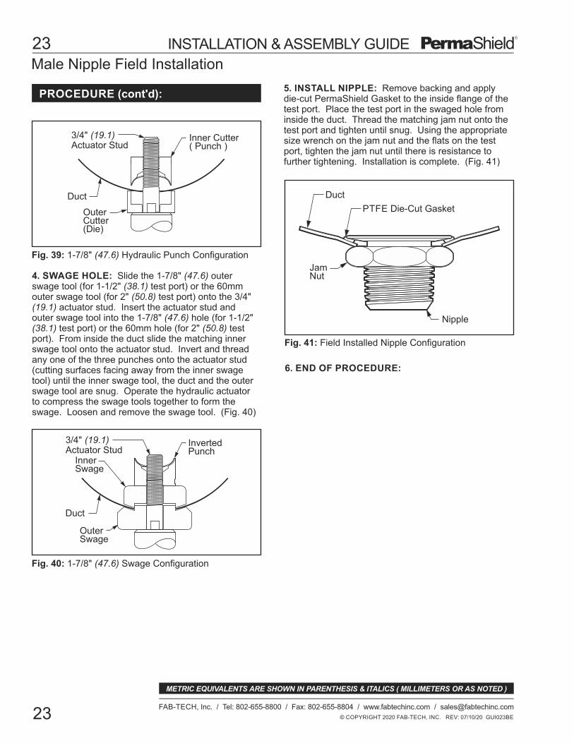
3. 1-7/8 (47.6) PUNCH: Slide the 1-7/8" (47.6) die(for 1-1/2" (38.1) test port) or the 60mm die (for 2"(50.8) test port) onto the 3/4" (19.1) actuator stud withthe open end of the die facing away from the actuator.Insert the 3/4" (19.1) actuator stud into the 3/4" (19.1)hole. From inside the duct thread the matching 1-7/8"(47.6) or 60mm punch onto the 3/4" (19.1) actuatorstud with the cutting surfaces of the punch toward theduct. Continue threading the punch by hand until thedie, duct and punch are snug. Operate the hydraulicactuator to draw the punch through the duct material.Remove the punch and die. (Fig. 39)
PROCEDURE: 1-1/2" (38.1) NIPPLE
onto the 3/8" (9.5) stud with the cutting surfaces of thepunch toward the duct. Continue threading the punchby hand until the die, duct and punch are snug.Operate the hydraulic actuator to draw the punchthrough the duct material. Remove the punch, die, 3/8"(9.5) stud and spacers. (Fig. 38)
2" (50.8) NIPPLE
Duct
3/4" (19.1)Actuator Stud
Inner Cutter( Punch )
OuterCutter(Die)
Nipple
PTFE Die-Cut Gasket
Duct
JamNut
Fig. 41: Field Installed Nipple Configuration
Fig. 39: 1-7/8" (47.6) Hydraulic Punch Configuration
Fig. 40: 1-7/8" (47.6) Swage Configuration
InvertedPunch
Duct
OuterSwage
InnerSwage
Male Nipple Field Installation
© COPYRIGHT 2020 FAB-TECH, INC. REV: 07/10/20 GUI023BE
23
FAB-TECH, Inc. / Tel: 802-655-8800 / Fax: 802-655-8804 / www.fabtechinc.com / [email protected]
23
METRIC EQUIVALENTS ARE SHOWN IN PARENTHESIS & ITALICS ( MILLIMETERS OR AS NOTED )
INSTALLATION & ASSEMBLY GUIDE
PROCEDURE (cont'd):
3/4" (19.1)Actuator Stud
5. INSTALL NIPPLE: Remove backing and applydie-cut PermaShield Gasket to the inside flange of thetest port. Place the test port in the swaged hole frominside the duct. Thread the matching jam nut onto thetest port and tighten until snug. Using the appropriatesize wrench on the jam nut and the flats on the testport, tighten the jam nut until there is resistance tofurther tightening. Installation is complete. (Fig. 41)
4. SWAGE HOLE: Slide the 1-7/8" (47.6) outerswage tool (for 1-1/2" (38.1) test port) or the 60mmouter swage tool (for 2" (50.8) test port) onto the 3/4"(19.1) actuator stud. Insert the actuator stud andouter swage tool into the 1-7/8" (47.6) hole (for 1-1/2"(38.1) test port) or the 60mm hole (for 2" (50.8) testport). From inside the duct slide the matching innerswage tool onto the actuator stud. Invert and threadany one of the three punches onto the actuator stud(cutting surfaces facing away from the inner swagetool) until the inner swage tool, the duct and the outerswage tool are snug. Operate the hydraulic actuatorto compress the swage tools together to form theswage. Loosen and remove the swage tool. (Fig. 40)
6. END OF PROCEDURE:

Fig. 42: 3/8" (9.5) Test Port Configuration
Fig. 43: Insert Test Port into duct
Fig. 44: Install Seal Fig. 45: Seat the Seal
Fig. 46: Install Nut and Remove Handle
Use cautionto prevent the test portfrom droppinginto the duct.
Test Port (Lollipop) Field Installation: 3/8" (9.5), 3/4" (19.1) & 2" (50.8)
SEAL
HEX NUT
REMOVEABLE HANDLE
NPT
TEST PORT
SEAL GROOVE
© COPYRIGHT 2020 FAB-TECH, INC. REV: 07/10/20 RND024BC
24
FAB-TECH, Inc. / Tel: 802-655-8800 / Fax: 802-655-8804 / www.fabtechinc.com / [email protected]
24
METRIC EQUIVALENTS ARE SHOWN IN PARENTHESIS & ITALICS ( MILLIMETERS OR AS NOTED )
INSTALLATION & ASSEMBLY GUIDE
TOOLS REQUIRED:
1. DRILL HOLE IN DUCT: For this procedure, theduct does not need to be removed from the system andthe port can be installed in duct as small as 2" (50.8)diameter. Mark the desired location for the test portand center punch. Drill a 1/8" (3.2) starter hole at thecenter punch location. Slowly enlarge the hole with astep drill to .750" (19.1) diameter hole in the duct.
2. DEBUR THE HOLE: Carefully debur the holeremoving all metal and coating debris.
3. APPLY ACCROLUBE TO SEAL: Take the tube ofAccrolube and use the tab ears to rip and twist the tipoff. Hold the seal with the flared side toward you andapply a generous bead of Accrolube in the seal groove.
Electric, Pneumatic, or Battery Powered DrillDrill Bit Set and Step Drill to 3/4" (19.1) Min Dia.Center PunchHalf Round and Flat File (fine)Calibrated Torque Wrench
PROCEDURE: 3/8" (9.5) TEST PORT4. INSERT TEST PORT: Work the test port into thehole until just the handle is showing outside the hole.(Fig. 43)
5. INSTALL SEAL: Slide the seal, flared side awayfrom the hole onto the handle. Using thumb and fore-finger, squeeze the seal together and work it into thehole around the handle. (Fig. 44)
6. SEAT THE SEAL: With the seal inside the ductand positioned on the test port shoulder, seat the seallip in the hole by firmly pulling the handle so that thetest port threads slide through the seal and protrudefrom the duct hole. Ensure that the seal lip is stillseated in the hole. (Fig. 45)
7. INSTALL NUT: Next, slide the nut onto the handleand thread the nut until it contacts the duct. Finaltightening is with a calibrated torque wrench to 15 in-lbs(1.7 Nm). (Fig. 46)
8. REMOVE HANDLE: The removable handle may beleft in place as a temporary plug. Remove the handleto access a 1/16" (1.6) NPT tapped hole for installing afitting of choice. The 3/8" (9.5) Test Port may becounter drilled to a maximum bore of 3/8" (9.5) ID forother installations. (Fig. 46)
9. END OF PROCEDURE:

Fig. 47: 3/4" (19.1) Test Port Cut-away
SEAL
HEXNUT
REMOVABLEHANDLE
TESTPORT
DUCT
© COPYRIGHT 2020 FAB-TECH, INC. REV: 07/10/20 GUI025BC
25
FAB-TECH, Inc. / Tel: 802-655-8800 / Fax: 802-655-8804 / www.fabtechinc.com / [email protected]
25
METRIC EQUIVALENTS ARE SHOWN IN PARENTHESIS & ITALICS ( MILLIMETERS OR AS NOTED )
INSTALLATION & ASSEMBLY GUIDE
PROCEDURE: 3/4" TEST PORT
TOOLS REQUIRED:
Electric, Pneumatic, or Battery Powered DrillDrill Bit Set and Step Drill to 1-3/8" (34.9) Min Dia.Center PunchHalf Round and Flat File (fine)Calibrated Torque Wrench
Test Port (Lollipop) Field Installation: 3/8" (9.5), 3/4" (19.1) & 2" (50.8)
8. REMOVE HANDLE : The removable handlemay be left in place as a temporary plug. Remove thehandle to access a 1/4" (6.35) NPT tapped hole forinstalling a fitting of choice. The 3/4" (19.1) Test Portmay also be drilled to a maximum bore of 3/4" (19.1)ID for other fitting installations. (Fig. 46)
9. END OF PROCEDURE:
1. DRILL HOLE IN DUCT: For this procedure, theduct does not need to be removed from the system andthe port can be installed in duct as small as 6" (152.4)diameter. Slowly enlarge the hole with a step drill to1-3/8" (34.9) diameter hole in the duct.
2. DEBUR THE HOLE: Carefully debur the holeremoving all metal and coating debris.
3. APPLY ACCROLUBE TO SEAL: Take the tubeof Accrolube and use the tab ears to rip and twist the tipoff. Hold the seal with the flared side toward you andapply a generous bead of Accrolube in the seal groove.
4. INSERT TEST PORT: Work the test port into thehole until just the handle is showing outside the hole.(Fig. 43)
5. INSTALL SEAL: Slide the seal, flared sideaway from the hole, onto the handle. Using thumb andforefinger, squeeze the seal together and work the sealinto the hole around the handle. (Fig. 44)
6. SEAT THE SEAL: With the seal inside the ductand positioned on the test port shoulder, seat the seallip in the hole by firmly pulling the handle so that thetest port threads slide through the seal and protrudefrom the duct hole. Ensure that the seal lip is stillseated in the hole. (Fig. 45)
7. INSTALL NUT: Next, slide the nut onto thehandle and thread the nut until it contacts the duct.Final tightening is with a calibrated torque wrench to250 in-lbs (28.2 Nm). (Fig. 46)
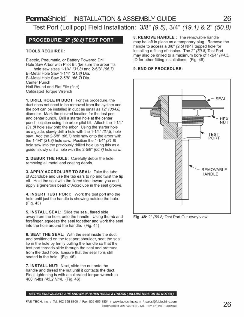
SEAL
HEXNUT
REMOVABLEHANDLE
Fig. 48: 2" (50.8) Test Port Cut-away view
TOOLS REQUIRED:
Electric, Pneumatic, or Battery Powered DrillHole Saw Arbor with Pilot Bit (be sure the arbor fits hole saw sizes 1-1/4" (31.8) and 2-5/8" (66.7)Bi-Metal Hole Saw 1-1/4" (31.8) Dia.Bi-Metal Hole Saw 2-5/8" (66.7) Dia.Center PunchHalf Round and Flat File (fine)Calibrated Torque Wrench
Test Port (Lollipop) Field Installation: 3/8" (9.5), 3/4" (19.1) & 2" (50.8)
TESTPORT
© COPYRIGHT 2020 FAB-TECH, INC. REV: 07/10/20 RND026BC
26
FAB-TECH, Inc. / Tel: 802-655-8800 / Fax: 802-655-8804 / www.fabtechinc.com / [email protected]
26
METRIC EQUIVALENTS ARE SHOWN IN PARENTHESIS & ITALICS ( MILLIMETERS OR AS NOTED )
INSTALLATION & ASSEMBLY GUIDE
PROCEDURE: 2" (50.8) TEST PORT8. REMOVE HANDLE : The removable handlemay be left in place as a temporary plug. Remove thehandle to access a 3/8" (9.5) NPT tapped hole forinstalling a fitting of choice. The 2" (50.8) Test Portmay also be drilled to a maximum bore of 1-3/4" (44.5)ID for other fitting installations. (Fig. 46)
9. END OF PROCEDURE:
1. DRILL HOLE IN DUCT: For this procedure, theduct does not need to be removed from the system andthe port can be installed in duct as small as 12" (304.8)diameter. Mark the desired location for the test portand center punch. Drill a starter hole at the centerpunch location using the arbor pilot bit. Attach the 1-1/4"(31.8) hole saw onto the arbor. Using the starter holeas a guide, slowly drill a hole with the 1-1/4" (31.8) holesaw. Add the 2-5/8" (66.7) hole saw onto the arbor withthe 1-1/4" (31.8) hole saw. Position the 1-1/4" (31.8)hole saw into the previously drilled hole using this as aguide, slowly drill a hole with the 2-5/8" (66.7) hole saw.
2. DEBUR THE HOLE: Carefully debur the holeremoving all metal and coating debris.
3. APPLY ACCROLUBE TO SEAL: Take the tubeof Accrolube and use the tab ears to rip and twist the tipoff. Hold the seal with the flared side toward you andapply a generous bead of Accrolube in the seal groove.
4. INSERT TEST PORT: Work the test port into thehole until just the handle is showing outside the hole.(Fig. 43)
5. INSTALL SEAL: Slide the seal, flared sideaway from the hole, onto the handle. Using thumb andforefinger, squeeze the seal together and work the sealinto the hole around the handle. (Fig. 44)
6. SEAT THE SEAL: With the seal inside the ductand positioned on the test port shoulder, seat the seallip in the hole by firmly pulling the handle so that thetest port threads slide through the seal and protrudefrom the duct hole. Ensure that the seal lip is stillseated in the hole. (Fig. 45)
7. INSTALL NUT: Next, slide the nut onto thehandle and thread the nut until it contacts the duct.Final tightening is with a calibrated torque wrench to400 in-lbs (45.2 Nm). (Fig. 46)

Fab-Tech Flange Assembly For Adapters
TOOLS REQUIRED:
Lint Free ClothScissors and/or Utility KnifeSocket Set with Deep SocketsCalibrated Torque Wrench
This procedure is intended to assist you in the properassembly of our 2" (50.9) and 3" (76.2) Fab-Tech flangejoint. All pieces are shipped in poly sheeting to helpprevent contamination and to protect the outer coatedsurface of the flange. Remove the pieces from the polysheeting and inspect the interior coated surface andthe outer flange surfaces to insure the integrity of thesystem. Do not, under any circumstances, install apiece of pip or fitting that has visible damage. Do notpenetrate the coating for any reason except whenusing approved modification systems. (Fig. 49)
"D"
Fab-TechFlange
.75"(19.1)
Duct
TightenClamp Nut
Buckle
DuctWelded to duct
ClampNut
PTFE Gasket
Fig. 49: Fab-Tech Flange Configuration
Fig. 50: Fab-Tech Flange Assembly
2" (50.8) - FTFL23" (76.2) - FTFL3
Adapter
© COPYRIGHT 2020 FAB-TECH, INC. REV: 07/10/20 GUI027BC
27
FAB-TECH, Inc. / Tel: 802-655-8800 / Fax: 802-655-8804 / www.fabtechinc.com / [email protected]
27
METRIC EQUIVALENTS ARE SHOWN IN PARENTHESIS & ITALICS ( MILLIMETERS OR AS NOTED )
INSTALLATION & ASSEMBLY GUIDE
4. Tighten Clamp: When both flanges are trappedunder the clamp band, reattach the buckle onto theclamp bolt and tighten the clamp nut until the jointsections stay together. Although this method of joiningduct is self aligning, visually inspect the joint to ensureproper alignment of the flanges and proper seating ofthe flanges in the clamp. When satisfied that thealignment of the clamp and flanges are correct, tightenthe clamp nut using a 7/16" (11.1) wrench untilresistance to further tightening is felt.
5. Torque Clamp Nut: Final tightening must be donewith a calibrated torque wrench. The recommendedtorque for 2" (50.8) & 3" (76.2) EZ clamps is 75 in lbs(6.25 ft lbs or 0.9 m kg). (Fig. 50)
PROCEDURE:
GENERAL:
1. POSITION CLAMP: To begin, clean the outsideflange surfaces to be joined with a soft damp cloth.Loosen and thread the clamp nut to the end of the bolt.Unclasp the buckle on the clamp. In this configurationthe clamp has some flexibility. With moderate force,open the clamp until you are able to slip the clamponto the flange welded to the duct.
2. APPLY GASKET: Always use a new gasket. Peelthe backing from the die-cut PTFE gasket to exposethe adhesive. Adhere the gasket approximatelycentered to one of the flange faces adhesive side down.Only one gasket required per joint. Firmly run yourfinger over the joint to guarantee complete adhesion.
3. BRING FLANGES TOGETHER: Carefullybring the piece to be installed into the clamp alreadypositioned in Step 1. This will take some practice.
6. END OF PROCEDURE:

Quadrant Arm
Fig. 51: 4" (101.6) - 14" (355.6) Industrial Damper Actuator Removal for Customer Supplied Actuator.
Blank Actuator Shaft
Blank Actuator Mounting Plate
Damper Actuator Field Installation
© COPYRIGHT 2020 FAB-TECH, INC. REV: 07/10/20 RND028BC
28
FAB-TECH, Inc. / Tel: 802-655-8800 / Fax: 802-655-8804 / www.fabtechinc.com / [email protected]
28
METRIC EQUIVALENTS ARE SHOWN IN PARENTHESIS & ITALICS ( MILLIMETERS OR AS NOTED )
INSTALLATION & ASSEMBLY GUIDE
GENERAL:
Fab-Tech’s standard PermaShield dampers aremanufactured in all sizes with a manual actuator.Pneumatic or electric actuators are also available asan option for all sizes of dampers. However, customersupplied actuators are also an option. This procedurecovers the steps required to modify each of the type ofdampers in the field to accept a customer supplliedactuator. Since this procedure cover the full range ofdampers from 4" (101.6) to 120" (3048.0) diameter, thesteps described below are general in nature.
PROCEDURE:
TOOLS REQUIRED:
Custom Actuator KitBlank Actuator Mounting PlateBlank Actuator ShaftAssorted Box WrenchesAssorted Allen Wrenches
1. REMOVE MANUAL ACTUATOR: For all sizesof dampers, reference the appropriate illustration toremove the manual actuator, mounting plate andactuator shaft. (Fig. 56, 57,58, 59) Set these itemsaside.
2. MACHINE BLANK ACTUATOR SHAFT: Take theblank actuator shaft and have it machined to mate withthe customer supplied actuator.
3. MODIFY BLANK ACTUATOR MOUNTING PLATE:Take the blank actuator mounting plate and have itdrilled with the correct size and number of holes tomount the customer supplied actuator.
4. ACTUATOR ASSEMBLY: Attach the customersupplied actuator onto the modified actuator mountingplate. Install the new actuator, actuator mounting plateand shaft onto the damper. Reuse the hardwareremoved in Step 1 to install the actuator mounting plateand reuse the setscrew to attach the modified actuatorshaft to the damper blade shaft.
5. TEST ACTUATOR: Test new actuator to insurethat the damper operates properly.
6. END OF PROCEDURE:
TECHNICAL ASSISTANCE:
For technical assistance, contact the Fab-TechEngineering Department at (802) 655-8800.

Fig. 53: 36" (914.4) - 48" (1219.2) Heavy Duty Industrial Damper Actuator Removal for Customer Supplied Actuator.
Fig. 52: 16" (406.4) - 34" (863.6) Heavy Duty Industrial Damper Actuator Removal for Customer Supplied Actuator.
Blank Actuator Shaft
Blank ActuatorMounting Plate
Blank Actuator Shaft
Blank ActuatorMounting Plate
Quadrant Arm
ActuatorMounting Plate
Damper Actuator Field Installation
© COPYRIGHT 2020 FAB-TECH, INC. REV: 07/10/20 GUI029BC
29
FAB-TECH, Inc. / Tel: 802-655-8800 / Fax: 802-655-8804 / www.fabtechinc.com / [email protected]
29
METRIC EQUIVALENTS ARE SHOWN IN PARENTHESIS & ITALICS ( MILLIMETERS OR AS NOTED )
INSTALLATION & ASSEMBLY GUIDE
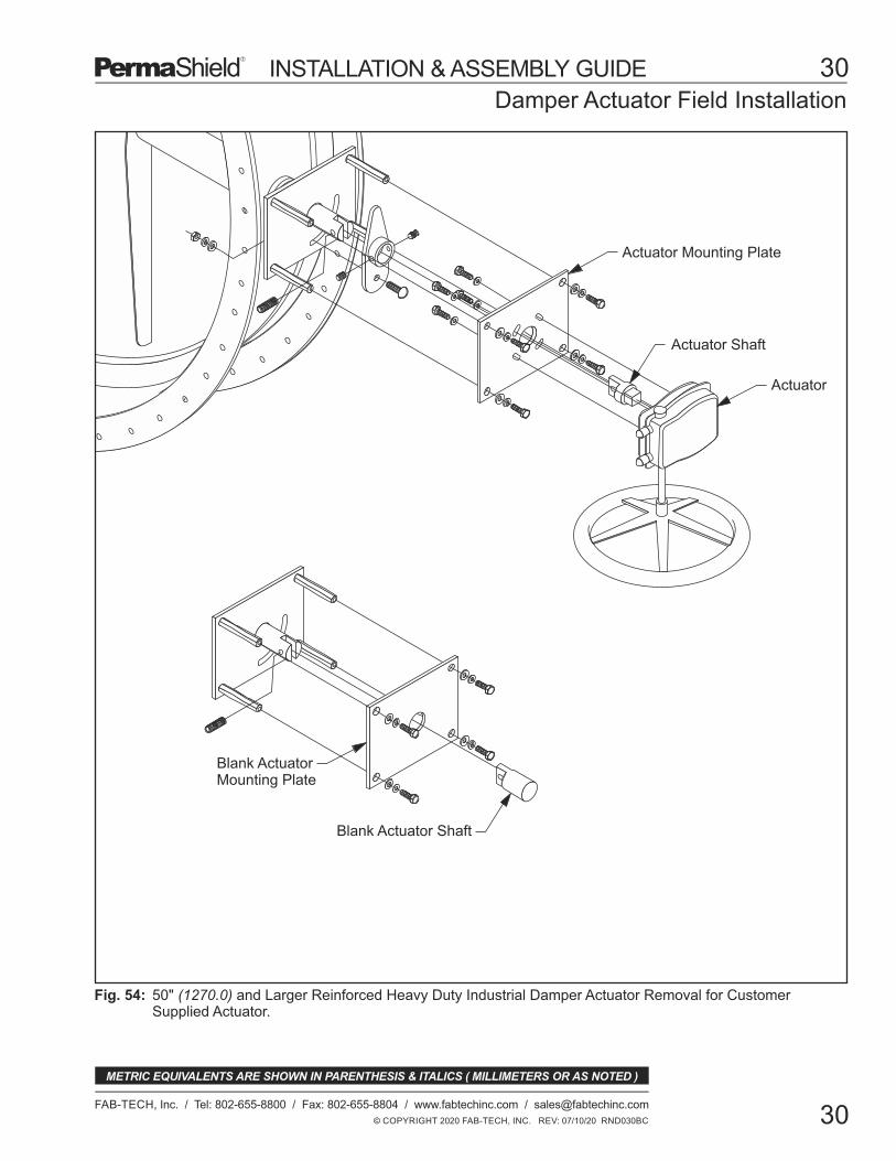
Fig. 54:
Damper Actuator Field Installation
Blank Actuator Shaft
Blank ActuatorMounting Plate
Actuator Mounting Plate
Actuator Shaft
Actuator
© COPYRIGHT 2020 FAB-TECH, INC. REV: 07/10/20 RND030BC
30
FAB-TECH, Inc. / Tel: 802-655-8800 / Fax: 802-655-8804 / www.fabtechinc.com / [email protected]
30
METRIC EQUIVALENTS ARE SHOWN IN PARENTHESIS & ITALICS ( MILLIMETERS OR AS NOTED )
INSTALLATION & ASSEMBLY GUIDE
50" (1270.0) and Larger Reinforced Heavy Duty Industrial Damper Actuator Removal for CustomerSupplied Actuator.
Normally the patch area does not need to be sanded.However, if the area requiring repair is caused by anabrasion then it may be necessary to locally lightlysand with 220 grit aluminum oxide sandpaper,removing all embedded contamination. All foreignmaterial must be removed from the patch area andsharp "edges" or bumps should be sanded smooth.In all cases, wipe the entire area with an alcoholmoistened lint free towel. Repeat using another cleanlint free towel. The patch should also be cleaned withalcohol.
© COPYRIGHT 2020 FAB-TECH, INC. REV: 06/15/21 GUI031BD
31
FAB-TECH, Inc. / Tel: 802-655-8800 / Fax: 802-655-8804 / www.fabtechinc.com / [email protected]
31
PermaShield Coating Repair with PermaPatch
METRIC EQUIVALENTS ARE SHOWN IN PARENTHESIS & ITALICS ( MILLIMETERS OR AS NOTED )
INSTALLATION & ASSEMBLY GUIDE
MATERIALS NEEDED:
PROCEDURE
Repair of small pinholes and abrasions on Fab-Tech'sPermaShield coated duct may be accomplished. Thisrepair protocol is appropriate for repairs no larger thana dime (1/2" (12.7) diameter). The patch materialcomes as clear 1" (25.4) diameter film dots and willprovide an overlap of 1/4" (6.35) around the entireperimeter of the damage/defect.
Contact Fab-Tech Engineering for specific restorationprotocol for larger repairs.
Work only in a well-lit and ventilated area as fumes willbe generated. If working in a confined area, follow yourcorporate confined space precautions, rememberingthat a heat source will be used. An NIOSH-approvedrespirator, not a dust mask, should be used if ventilation,is marginal. Safety glasses are required. Carefully readthe Safety Data Sheets (SDS) for the PermaPatchrepair film.
Fab-Tech PermaPatch Repair Kit, Item #PP-KIT (Contact Fab-Tech Sales at 802-655-8800)Electric Heat Gun: Milwaukee Veritemp Model #8977 with Concentrator Accessory #49-80-0297 or Bosch Heat Gun Model #1943LED with Concentrator #HG020Denatured Alcohol (or Alcohol Prep Pads)Tweezers#220 Grit Aluminum Oxide (A/O) SandpaperSafety GlassesNIOSH Approved Respirator with Hepa/Charcoal Combination Cartridge Filter
Fab-Tech's PermaShield Training Video has a shortsection on coating repair. This video is availableonline at www.fabtechinc.com/training_videos.php.
1. CLEAN THE IMMEDIATE AREA:
As this is a heat application process, make certain thatall tools and materials are "ready-to-go". The patcharea must not be allowed to cool from start to finish.Practice this patch technique on a Fab-Tech coatedcoupon for practice.
Using the Heat Gun set to 820-850°F (440-455°C)uniformly preheat in and around the area to be patched.Stop preheating at the time when the area becomesglazed over. Caution: Avoid overheating which canburn the coating.
While maintaining the heat and glaze, using tweezers,center the patch carefully over the area. Using ePTFEmaterial, press the patch into softened coating. Patchshould have a minimum 1/4" (6.35) clearance aroundthe coating.
Using the heat gun in an even circular motion, heat thepatch and area until no gaps or voids are present. Theproperly repaired area should be fee of bubbles, foldsand raised edges.Caution: Avoid overheating which can burn the coating.
After the patch has cooled, follow the approved "spark"testing protocol to assure that the area is "holiday" free.Refer to Spark Testing Protocol included in thisassembly guide.
If you need technical assistance, call the Fab-Tech Inc.Engineering Department at (802) 655-8800.
REPAIR PROCEDURE:
PERSONAL PROTECTION:
GENERAL:
5. TESTING THE PATCH:
TECHNICAL ASSISTANCE:
TRAINING VIDEO:
2. PREHEAT TO GLAZE:
3. TACKING THE PATCH:
4. FINAL REHEAT TO FLOW:

Ground cable
Electrode cable
On / Off switch
Remove blackscrew cap,set Numericselector to 8
Remove blackscrew cap,set Hi/Loselector to Lo
Fig. 55: D.E. Sterns Spark Tester
Fig. 56: Rear View of Spark TesterGROUND
OUTPUT
Spark Testing Protocol
© COPYRIGHT 2020 FAB-TECH, INC. REV: 07/10/20 RND032BC
32
FAB-TECH, Inc. / Tel: 802-655-8800 / Fax: 802-655-8804 / www.fabtechinc.com / [email protected]
32
METRIC EQUIVALENTS ARE SHOWN IN PARENTHESIS & ITALICS ( MILLIMETERS OR AS NOTED )
INSTALLATION & ASSEMBLY GUIDE
PermaSield products are 100% QC tested at thefactory for coating defects. However, there are timeswhen field spark testing is recommended. Inspect anyduct that may have been damaged during transport orinstallation, or has been field shortened or modified.
SPARK TESTER: The spark tester is a battery operatedhigh voltage, low amperage, voltage source. It isrecommended that a D.E. Stearns Holiday tester beused for this procedure. On the face of the unit is alarge black on/off switch. Below and to the left andright of this switch are the electrode and groundconnections. The ground cable has a copper coloredcable molded into the end. The electrode cable hasconnectors on each end. Connect the ground andelectrode cables to the appropriate cable connection.The connectors are quarter turn style. Insert androtate the connector until the slotted end engages.Moderate insertion force is normal. Turn the connectorclockwise to lock. The insulated wand and brushfixtures attach to the other end of the electrode cableusing the same connector style. (Fig. 54)
1. SET THE TESTER: On the back of the unit aretwo black, slotted screws caps. (Fig. 55) Removethese caps to expose the adjusting screws underneath.Set the spark tester to achieve 2500 volts. Set theHigh/Low selector to Low and set eh numeric selectorto eight. Test the unit by switching it on and groundingthe electrode brush against the ground strap. Theresulting audible tone should become noticeablylouder.
CAUTION: This device will bite. Although theamperage of the device is not dangerous, it will createan uncomfortable shock. Make sure that you do notcreate a ground path with your body.
2. GROUND STRAP: Make sure the ground strap isin contact with ONLY the base metal of the duct to betested (do not use loose rings or painted surfaces asground). Then check that the tester works by touchingthe duct metal with the brush. A good spark and anincrease in tone tells you that it is connected properly.
3. INSPECT DUCT: Inspect the duct coating. Makesure the area to be tested is clean and dry. Be carefulto draw the brush toward you; do not push the tips ofthe brush into the coating. The long brush can beused to inspect large areas of the inside of the ductin a sweeping motion.
GENERAL: PROCEDURE:
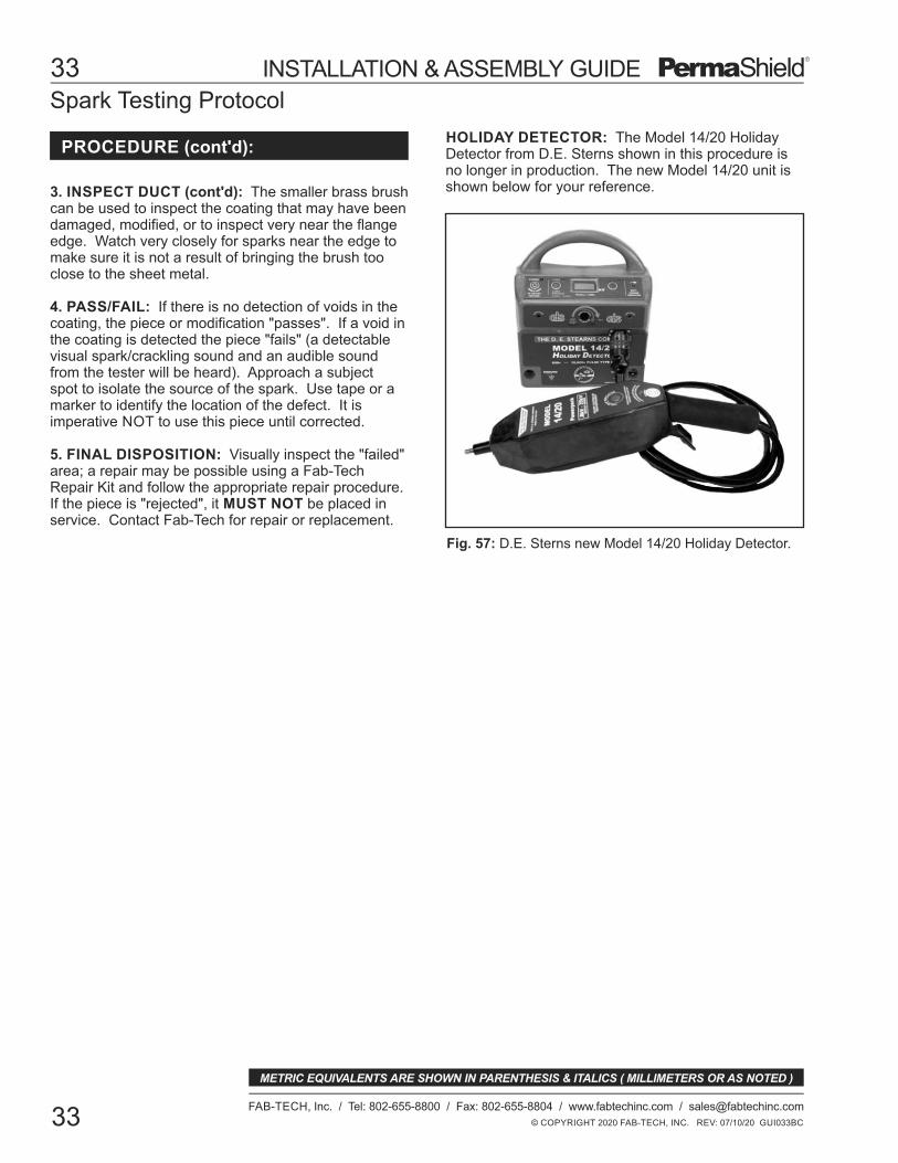
Spark Testing Protocol
Fig. 57: D.E. Sterns new Model 14/20 Holiday Detector.
HOLIDAY DETECTOR: The Model 14/20 HolidayDetector from D.E. Sterns shown in this procedure isno longer in production. The new Model 14/20 unit isshown below for your reference.
© COPYRIGHT 2020 FAB-TECH, INC. REV: 07/10/20 GUI033BC
33
FAB-TECH, Inc. / Tel: 802-655-8800 / Fax: 802-655-8804 / www.fabtechinc.com / [email protected]
33
METRIC EQUIVALENTS ARE SHOWN IN PARENTHESIS & ITALICS ( MILLIMETERS OR AS NOTED )
INSTALLATION & ASSEMBLY GUIDE
PROCEDURE (cont'd):
3. INSPECT DUCT (cont'd): The smaller brass brushcan be used to inspect the coating that may have beendamaged, modified, or to inspect very near the flangeedge. Watch very closely for sparks near the edge tomake sure it is not a result of bringing the brush tooclose to the sheet metal.
4. PASS/FAIL: If there is no detection of voids in thecoating, the piece or modification "passes". If a void inthe coating is detected the piece "fails" (a detectablevisual spark/crackling sound and an audible soundfrom the tester will be heard). Approach a subjectspot to isolate the source of the spark. Use tape or amarker to identify the location of the defect. It isimperative NOT to use this piece until corrected.
5. FINAL DISPOSITION: Visually inspect the "failed"area; a repair may be possible using a Fab-TechRepair Kit and follow the appropriate repair procedure.If the piece is "rejected", it MUST NOT be placed inservice. Contact Fab-Tech for repair or replacement.

Standard
Electric double cut shears (Milwaukee 6850 or equiv )
Flexible metal ruler and/or tape measure
Marking pen and/or scribe
Calculator and writing pad
Protective gloves
Electric or pneumatic drill
Center punch
Drill bit set and step drill to 1/2" (13mm) min diameter
Hacksaw with blades (32 or 40 teeth per inc.)
Socket set with deep sockets for EZ clamp bolts
Torque wrench 0-50 lb*ft (0-70NM)
Half round and flat file (fine)
Hard rubber or leather mallet (must be clean and new)
Scissors and/or utility knife
Large adjustable wrenches (tighten adapter locknuts)
Allen wrenches for assembling split colars
Soft cloths for cleaning
Alcohol for cleaning
Special
Hydraulic punch kit (Fab-Tech PN TPS02)
Mechanical punch kit (Fab-Tech PN TPS01)
EZ pliers (Fab-Tech PN ezpliers)
Saw guides for cutting 2" & 3" (50.8mm & 76.2mm) EZ duct (Tri-Clover 2" model #07-1014-2A and 3" model #07-1014-3A)
Ridgid model S3 heavy duty pipe cutter (Fab-Tech PN D0700 custom roller)
Hand flanger - Pexto model 622 or equivilent (Custom rolls for hand flanger)
Recommended Tooling
© COPYRIGHT 2020 FAB-TECH, INC. REV: 07/10/20 RND034BC
34
FAB-TECH, Inc. / Tel: 802-655-8800 / Fax: 802-655-8804 / www.fabtechinc.com / [email protected]
34
The following is a list of tools and materials used in all the instruction sections of this guide.
METRIC EQUIVALENTS ARE SHOWN IN PARENTHESIS & ITALICS ( MILLIMETERS OR AS NOTED )
INSTALLATION & ASSEMBLY GUIDE