
Innovative Technology Limited
38
Innovative Technology Limited ® NV9 Bank Note Validating System The Future of Smiley ® Bank Note Handling Operations Manual GA326-3 © Copyright Innovative Technology Limited 2005
Transcript of Innovative Technology Limited

Innovative Technology Limited ®
NV9 Bank Note Validating System
The Future of Smiley® Bank Note Handling
Operations Manual
GA326-3
© Copyright Innovative Technology Limited 2005
NV9 Operations Manual GA326-3
Revision History
Innovative Technology Ltd
Title: NV9 Engineers Manual
Drawing No: GA326 Project:
Author: T. J. Crowley Date: 29/10/2004
Format: MS Word 2000
Issue Rel Date Mod By Comments
Issue 1 29/10/2004 TJC First draft Issue 2 21/06/2005 ATG Second draft
Issue 3 14/07/2005 RJS First Release
2 of 38
© Copyright Innovative Technology Limited 2005

NV9 Operations Manual GA326-3
Contents Page
1 INTRODUCTION..................................................................................................................................5
2: SCOPE OF DOCUMENT....................................................................................................................6
3: ENVIRONMENT AND POWER REQUIREMENTS............................................................................7
4: GENERAL DESCRIPTION.................................................................................................................8
5: NV9 USER INTERFACE ....................................................................................................................9
5.1:DIPswitch Settings ................................................................................................................................. 9
5.2:LED Status Codes ................................................................................................................................ 10
6: INTERFACES: HARDWARE DESCRIPTION..................................................................................11
6.1:Interface Connector Pin Details ........................................................................................................ 11
6.2:Input and Output Hardware Circuits................................................................................................ 12
6.3:Software Optional Serial Interface Input and Outputs................................................................ 12
7: MACHINE INTERFACES: PROTOCOLS ........................................................................................13
7.1:Parallel input and output: ................................................................................................................... 13
7.2:Pulse Stream Output ........................................................................................................................... 13
7.3: Binary Output - BIN ............................................................................................................................. 15
7.4:Simple Serial Input/Output – SIO...................................................................................................... 15
7.5 Smiley® Secure Protocol - SSP ........................................................................................................ 18
7.6 Multi-Drop Bus / Internal Communications Protocol (IF5) – MDB ........................................... 19
7.7 CCTalk Protocol – CCT........................................................................................................................ 20
7.8 Extended Interface / USA Serial – NIS ............................................................................................. 21
8 UPDATING CURRENCY AND FIRMWARE .....................................................................................22
8.1 ITL BNV Download Manager .............................................................................................................. 22
8.2 NV9 – NV9 Copy (Cloning).................................................................................................................. 22
8.3:NV9 – NV9 copy process. ................................................................................................................... 23
9: MECHANICAL INSTALLATION ......................................................................................................24
3 of 38
© Copyright Innovative Technology Limited 2005

NV9 Operations Manual GA326-3
9.1:Changing or removing the bezels .................................................................................................... 24
9.2:Changing or removing cash boxes.................................................................................................. 24
10 ROUTINE MAINTENANCE .............................................................................................................25
10.1 Cleaning ................................................................................................................................................ 25
10.2 Note Path Debris Clearing / Belt Changing ................................................................................. 26
11: FAULT FINDING ANALYSIS .........................................................................................................27
12 SUPPORT TOOLS...........................................................................................................................29
12.1 PC Currency Programming Software (ITL BNV Download Manager) ................................... 29
12.2 Internet Website support .................................................................................................................. 29
12.3 E-mail Support..................................................................................................................................... 29
APPENDIX A - DRAWINGS .................................................................................................................30
APPENDIX B - ESCROW CONTROL..................................................................................................35
APPENDIX C - INTERFACE TOOLS DA1 - DA2 ................................................................................36
APPENDIX D – WEBSITE REGISTRATION........................................................................................37
4 of 38
© Copyright Innovative Technology Limited 2005

NV9 Operations Manual GA326-3
1 Introduction
This manual describes the operation of the NV9 Bank note Validator as fitted with Firmware Version 3.15 or greater.
Caution
• This Product must be fitted with a 2 Amp fuse before use.
• The NV9 Validator is pin for pin compatible with NV7/8/10 but NOT pin for pin compatible with the NV2/3/4/4X or 5 series products.
We recommend that you study this manual as there are many new features permitting new uses and more secure applications.
If you do not understand any part of this manual please contact the factory for assistance. In this way we may continue to improve our product. Alternatively visit our web site at www.innovative-technology.co.uk
Innovative Technology Ltd.
Derker Street Oldham England OL1 4EQ Tel: +44 (0) 161 626 9999 Fax: +44 (0) 161 620 2090 Email: [email protected]
Web site www.innovative-technology.co.uk
Smiley® and the ITL Logo are international registered trademarks and they are the property of Innovative Technology Limited.
Innovative Technology has a number of European and International Patents and Patents Pending protecting this product. If you require further details please contact the factory.
Innovative Technology is not responsible for any loss, harm, or damage caused by the installation and use of this product. This does not affect your local statutory rights. If in doubt please contact Innovative Technology for details of any changes
5 of 38
© Copyright Innovative Technology Limited 2005

NV9 Operations Manual GA326-3
2: Scope of Document
This document is intended for those who will:
• Design the NV9 into items of equipment.
• Build equipment using the NV9.
• Install equipment containing the NV9.
• Maintain equipment containing the NV9.
Although information is included which will allow a degree of fault diagnosis and repair, it is recommended that for all but simple mechanical repairs the unit be returned to an approved service centre for repair.
Caution:
• Never exceed the recommended environmental and electrical limits.
• Do not attempt to lubricate the mechanisms as this may affect the note transport.
• Do not polish the lens as this may alter the optical characteristics.
• If the NV9 Validator is disassembled the unit must be re-calibrated/re initialised, following re-assembly.
Innovative Technology Ltd has a policy of continual product improvement. As a result the products supplied may vary from the specification described here.
6 of 38
© Copyright Innovative Technology Limited 2005

NV9 Operations Manual GA326-3
3: Environment and Power Requirements
Environment Minimum Maximum Temperature +3oC +50oC
Humidity 5% 95% Non condensing
Table 1 - Environmental Requirements
• If the input voltage falls below 11V the NV9 may not operate correctly (will reject notes). The amber status LED and front bezel lights will flash to indicate incorrect conditions
• It is recommended that the power supply used can supply at least 1.5Amps.
Caution:
Electrical Supply Minimum Maximum Supply Voltage (V dc) Absolute Limits 11V 15V
MDB IF5 Version Supply Voltage 18V 42V Supply Ripple Voltage 0 0.25V @100 Hz
Supply Currents: Standby 0.35A
Validating 1A Peak (Stacker Motor stall) 1.5A
Table 2 - Power Requirements
7 of 38
© Copyright Innovative Technology Limited 2005

NV9 Operations Manual GA326-3
4: General Description NV9 Validator - the next generation of Smiley® Bank Note Validators
The NV9 Bank Note System is a compact note-validating machine (see figure 1), suitable for most money machines. It will accept up to 15 different denominations of notes in the serial control mode or 4 different notes in parallel mode, and will cope with different designs of banknote having the same value such as are found in the United Kingdom and Scotland.
DIPswitches
Status LEDs
Clip On Cash Box
Lo m
H
Figure 1 – The NV9 with Vertical and Universal B
The NV9 Validator leaves the factory preset to at least one currency so that it iinstallation. If it is required to change the currency data set this may be done ucurrency cloning system or the PC based Currency Management software.
New currencies and applications are being tested all the time, please refer to ofactory for information concerning specific currencies if they are not already inc
The NV9 is designed for easy installation in most machines. The stepped “sminotes with one hand and simplifies the note handling mechanism.
Interfacing the Validator is very simple, with the choice of the following protoco
• Parallel open collector outputs. • Pulse stream open collector output. • Binary open collector output. • Smiley® Secure Protocol (SSP) secure serial communications. • Simple serial I/O communications. • MDB interface protocol. • CCTalk • Extended Interface / USA Serial
8 of 38
© Copyright Innovative Technology Limited 200
Vertical And orizontal Bezel
Bezel cking Ar
Interface Connector
ezels
s ready for immediate sing either the NV9 to NV9
ur web site or contact the luded on our approved list.
ling mouth” allows insertion of
ls:
5

NV9 Operations Manual GA326-3
5: NV9 User Interface The user interface with the NV9 is shown below (see figure 2). It is simply a set of four DIPswitches and one red and one green LED, mounted on the top of the NV9. The DIPswitches set the basic operating mode of the unit, while the LED’s indicate the operational status of the NV9.
N
1
Figure
5.1:DIPswitch Settings The four DIPswitches can be set to a comrequired for the particular NV9.
Switch 1 – Spare
Switch 1 currently has no function and is
Switch 2 – pulse multiplier
This switch is used to modify the behavioswitch are covered in the interfaces’ desc
Currently the only interface to make use oto multiply the number of pulses given bythe switch is up the multiplier is 4.
Switches 3 and 4 – Machine Interface p
These switches are used to select the mashown below, (see table 1).
©
ON DIP
S 2 3 4
Pulse Multiplier
2 - User Display and DIPswitch Sett
bination of either up or down dep
reserved for future use.
ur of the selected machine interface. Dription in this manual.
f this switch is the pulse mode. In this a factor of four. When the switch is do
rotocol selection
chine interface to be used. The NV9 s
9 of 38 Copyright Innovative Technology Limited 2005
GREE
S
in
e
e
mw
u
RED
TATUS
s
1 Interface Pulse.S.P.
Special
4
3 2Parallel
AMBER
gs
nding on the configuration
tails of the function of this
ode the switch can be used n the multiplier is 1, when
pports four interfaces, as

NV9 Operations Manual GA326-3
Interface Switch 3 Switch 4 Parallel Down Down Pulse Down Up SSP Up Down
Special Up Up
Table 1 - Switch 3 and 4 Machine Interface Selection
The details of the parallel, pulse, and SSP can be found in the machine interface protocols section of this manual.
The special interface depends on the firmware that is used in the NV9, the firmware shipped as standard is the binary interface (World Wide) and CCTalk (UK only). However, there are other options that can be downloaded by the user:
• Binary
• CCTalk
• ITL Simple serial I/O
• MDB
Information on each of these interfaces can be found in the ‘machine interfaces protocol section’ of this manual.
5.2:LED Status Codes The three status LED’s are located to the right of the DIPswitches on the top of the unit and are used to indicate a variety of status signals. The red status is used to indicate system problems, while the green status indicates system health; these are described below in table 2.
LED Status Description Slow flashing green led Heartbeat (Slow = 1 second period)
In normal RUN operation, when the NV9 is ready to read a note, the green status led will flash slowly ("Heartbeat") to signal a “healthy” status.
Flashing red one second period NV9 is jammed, somewhere in the note path Fast flashing red (fast = half second period) NV9 cannot calibrate, sensor(s) may be blocked Permanent Red Memory has been corrupted Alternately flashing green then red Stacker is full Flashing amber and bezel lights Power supply is incorrect, check specification
Table 2 - LED Status Codes
10 of 38
© Copyright Innovative Technology Limited 2005
NV9 Operations Manual GA326-3
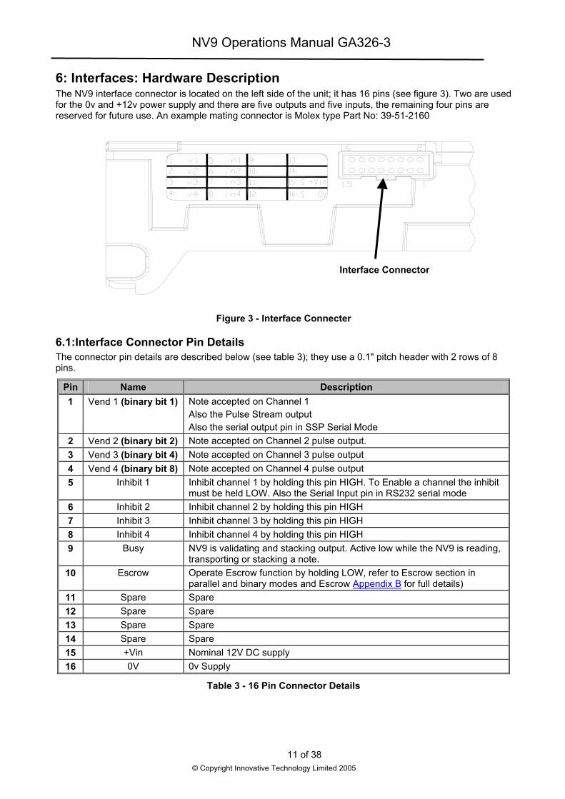
6: Interfaces: Hardware Description The NV9 interface connector is located on the left side of the unit; it has 16 pins (see figure 3). Two are used for the 0v and +12v power supply and there are five outputs and five inputs, the remaining four pins are reserved for future use. An example mating connector is Molex type Part No: 39-51-2160
r
Figure 3 - Interface Conne
6.1:Interface Connector Pin Details The connector pin details are described below (see table 3); they upins.
Pin Name Des1 Vend 1 (binary bit 1) Note accepted on Channel 1
Also the Pulse Stream output Also the serial output pin in SSP Se
2 Vend 2 (binary bit 2) Note accepted on Channel 2 pulse3 Vend 3 (binary bit 4) Note accepted on Channel 3 pulse4 Vend 4 (binary bit 8) Note accepted on Channel 4 pulse5 Inhibit 1 Inhibit channel 1 by holding this pin
must be held LOW. Also the Serial6 Inhibit 2 Inhibit channel 2 by holding this pin7 Inhibit 3 Inhibit channel 3 by holding this pin8 Inhibit 4 Inhibit channel 4 by holding this pin9 Busy NV9 is validating and stacking outp
transporting or stacking a note. 10 Escrow Operate Escrow function by holdin
parallel and binary modes and Esc11 Spare Spare 12 Spare Spare 13 Spare Spare 14 Spare Spare 15 +Vin Nominal 12V DC supply 16 0V 0v Supply
Table 3 - 16 Pin Connector D
11 of 38
© Copyright Innovative Technology Limited
Interface Connecto
cter
se a 0.1" pitch header with 2 rows of 8
cription
rial Mode output. output output HIGH. To Enable a channel the inhibit
Input pin in RS232 serial mode HIGH HIGH HIGH ut. Active low while the NV9 is reading,
g LOW, refer to Escrow section in row Appendix B for full details)
etails
2005

NV9 Operations Manual GA326-3
6.2:Input and Output Hardware Circuits
Caution: The output low signal is affected by the value of the pull up resistor on the host machine interface. Ensure your signal LOW levels comply with the 74HC CMOS series specification for reliable operation, (see figure 4).
Figure 4 - Input and Output Circuit
• All outputs are open collector transistors.
• All Inputs are held high to internal +5v via 10KΩ. The input structure is a CMOS gate with anti-static protection fitted.
Interface Logic levels Logic Low Logic High Inputs 0V < Low < 0.5 +3.7V < High <12V
Outputs with 2K2Ω pull up 0.6V Pull up voltage of host interface Maximum Current Sink 50mA per output
Table 4 - Interface Logic Levels
6.3:Software Optional Serial Interface Input and Outputs
Caution: The serial interfaces will only work if the relevant interface software is correctly installed.
Name Description SSP TxD Vend 1 SSP RxD Inhibit 1
Table 5 - Software Optional Serial Interface Inputs and Outputs
12 of 38
© Copyright Innovative Technology Limited 2005
NV9 Operations Manual GA326-3
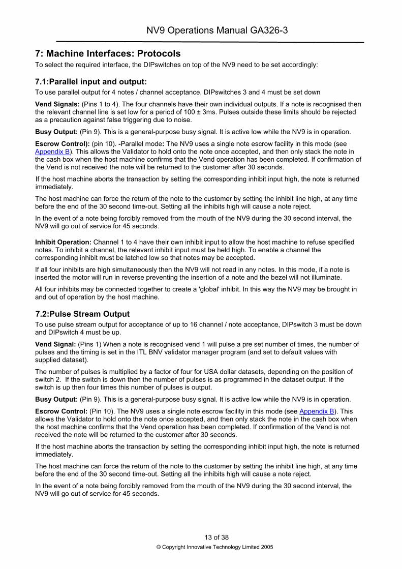
7: Machine Interfaces: Protocols To select the required interface, the DIPswitches on top of the NV9 need to be set accordingly:
7.1:Parallel input and output: To use parallel output for 4 notes / channel acceptance, DIPswitches 3 and 4 must be set down
Vend Signals: (Pins 1 to 4). The four channels have their own individual outputs. If a note is recognised then the relevant channel line is set low for a period of 100 ± 3ms. Pulses outside these limits should be rejected as a precaution against false triggering due to noise.
Busy Output: (Pin 9). This is a general-purpose busy signal. It is active low while the NV9 is in operation.
Escrow Control): (pin 10). -Parallel mode: The NV9 uses a single note escrow facility in this mode (see Appendix B). This allows the Validator to hold onto the note once accepted, and then only stack the note in the cash box when the host machine confirms that the Vend operation has been completed. If confirmation of the Vend is not received the note will be returned to the customer after 30 seconds.
If the host machine aborts the transaction by setting the corresponding inhibit input high, the note is returned immediately.
The host machine can force the return of the note to the customer by setting the inhibit line high, at any time before the end of the 30 second time-out. Setting all the inhibits high will cause a note reject.
In the event of a note being forcibly removed from the mouth of the NV9 during the 30 second interval, the NV9 will go out of service for 45 seconds.
Inhibit Operation: Channel 1 to 4 have their own inhibit input to allow the host machine to refuse specified notes. To inhibit a channel, the relevant inhibit input must be held high. To enable a channel the corresponding inhibit must be latched low so that notes may be accepted.
If all four inhibits are high simultaneously then the NV9 will not read in any notes. In this mode, if a note is inserted the motor will run in reverse preventing the insertion of a note and the bezel will not illuminate.
All four inhibits may be connected together to create a 'global' inhibit. In this way the NV9 may be brought in and out of operation by the host machine.
7.2:Pulse Stream Output To use pulse stream output for acceptance of up to 16 channel / note acceptance, DIPswitch 3 must be down and DIPswitch 4 must be up.
Vend Signal: (Pins 1) When a note is recognised vend 1 will pulse a pre set number of times, the number of pulses and the timing is set in the ITL BNV validator manager program (and set to default values with supplied dataset).
The number of pulses is multiplied by a factor of four for USA dollar datasets, depending on the position of switch 2. If the switch is down then the number of pulses is as programmed in the dataset output. If the switch is up then four times this number of pulses is output.
Busy Output: (Pin 9). This is a general-purpose busy signal. It is active low while the NV9 is in operation.
Escrow Control: (Pin 10). The NV9 uses a single note escrow facility in this mode (see Appendix B). This allows the Validator to hold onto the note once accepted, and then only stack the note in the cash box when the host machine confirms that the Vend operation has been completed. If confirmation of the Vend is not received the note will be returned to the customer after 30 seconds.
If the host machine aborts the transaction by setting the corresponding inhibit input high, the note is returned immediately.
The host machine can force the return of the note to the customer by setting the inhibit line high, at any time before the end of the 30 second time-out. Setting all the inhibits high will cause a note reject.
In the event of a note being forcibly removed from the mouth of the NV9 during the 30 second interval, the NV9 will go out of service for 45 seconds.
13 of 38
© Copyright Innovative Technology Limited 2005

NV9 Operations Manual GA326-3
Inhibit Operation: Each channel (1 to 4) has its own inhibit input to allow the host machine to refuse specified values of notes. To inhibit a channel, the relevant inhibit input must be held high. To enable a channel the corresponding inhibit must be latched low so that notes may be accepted.
Note: Channels higher than four cannot be individually inhibited, but will be globally inhibited if inhibits 1 to 4 are inhibited.
If all four inhibits are high simultaneously then the NV9 will not read in any notes. All four inhibits may be connected together to create a 'global' inhibit. In this way the NV9 may be brought in and out of operation by the host machine.
14 of 38
© Copyright Innovative Technology Limited 2005

NV9 Operations Manual GA326-3
7.3: Binary Output - BIN To use binary output DIPswitches 3 & 4 must both be up and the BIN option of the interface firmware must be loaded into the NV9.
In the event that the machine needs more than 4 notes to be recognised, but the host machine cannot take advantage of the serial communication methods then the NV9 can be set to give a binary pattern output on the four parallel output pins.
If the NV9 is set to binary mode it will issue the vend signals as a binary pattern on the parallel outputs for 100 ± 3ms. In this way a maximum of 15 different notes can be accepted and 4 notes individually inhibited.
Vend Signals: (Pins 1 to 4). The four channels have their own individual outputs. If a note is recognised the binary representation of the channel number will be pulled low for 100 ± 3ms. Pulses outside these limits will be rejected as a precaution against false triggering due to noise.
Busy Output: (Pin 9). This is a general-purpose busy signal. It is active low while the NV9 is in operation.
Escrow Control: (pin 10). The NV9 uses a single note escrow facility in this mode (see Appendix B). This allows the Validator to hold onto the note once accepted, and then only stack the note in the cash box when the host machine confirms that the Vend is completed. If confirmation of the Vend is not received then the note will be returned to the customer after 30 seconds.
If the host machine aborts the transaction by setting the corresponding inhibit input high on pin 10, the note is returned immediately.
The host machine can force the return of the note to the customer by setting the inhibit line high, at any time before the end of the 30 second time-out. Setting all the inhibits high will cause a note reject.
In the event of a note being forcibly removed from the mouth of the NV9 during the 30 second interval, the NV9 will go out of service for 45 seconds.
Inhibit Operation: Each channels (1 to 4) have their individual inhibit input to allow the host machine to refuse specified values of notes. To inhibit a channel, the relevant inhibit input must be held high. To enable a channel the corresponding inhibit must be latched low so that notes may be accepted.
Note: Channels higher than four cannot be individually inhibited, but will be globally inhibited if inhibits 1 to 4 are inhibited.
If all four inhibits are high simultaneously then the NV9 will not read in any notes. All four inhibits may be connected together to create a 'global' inhibit. In this way the NV9 may be brought in and out of operation by the host machine.
7.4:Simple Serial Input/Output – SIO Existing Smiley® NV4 users may already be using the serial input/output facility in conjunction with the parallel inputs. The NV9 Validator also supports this system. However this interface is not recommended for new designs, the Smiley® Secure Protocol SSP interface is recommended.
Caution:
• The NV9 does not support the Simple serial data out only mode as available on NV4. It only supports the serial data Input/Output mode.
• The host machine does not echo messages back to the Validator.
• The NV9 does not operate in true RS232 mode. (Only TTL level)
• The NV9 will not be enabled in serial I/O mode if Inhibit 3 line is held low when the unit is powered up
To use simple serial mode, DIPswitches 3 & 4 must both be up and the Simple Serial mode SIO option of the interface firmware must be loaded into the NV9.
Commands are provided to fully control the operation of the NV9, the notes to be accepted and rejected can be set and a single escrow mode can be enabled. In simple serial mode single byte commands are transmitted to the Validator, the Validator echoes each valid command it receives.
15 of 38
© Copyright Innovative Technology Limited 2005

NV9 Operations Manual GA326-3
The serial I/O mode will work at 9600 Baud rate if Inhibit 2 line is held low when the NV9 is powered up. The NV9 will not be enabled in serial I/O mode if Inhibit 3 line is held low when the unit is powered up. The data is formatted as follows:
Vend 1(pin 1)
idle start bit 0 bit 1 bit 2 bit 3 bit 4 bit 5 bit 6 bit 7 stop stop idle
3.3ms 0 0 1 0 1 0 0 0 = 20dec
1-start bit 8-data bits 2-stop bits 300 baud.
Figure- 5 Typical Serial Output: Transmission of the value 20 (decimal), Note not recognized
The NV9 will receive and transmit the following event codes:
NV9 Recognised Receive Codes NV9 Transmitted codes MESSAGE DECIMAL VALUE MESSAGE DECIMAL VALUE
Inhibit C1 131 Note Accept on C1 1
Inhibit C2 132 Note Accept on C2 2 Inhibit C3 133 Note Accept on C3 3 Inhibit C4 134 Note Accept on C4 4 Inhibit C5 135 Note Accept on C5 5 Inhibit C6 136 Note Accept on C6 6 Inhibit C7 137 Note Accept on C7 7 Inhibit C8 138 Note Accept on C8 8 Inhibit C9 139 Note Accept on C9 9
Inhibit C10 140 Note Accept on C10 10 Inhibit C11 141 Note Accept on C11 11 Inhibit C12 142 Note Accept on C12 12 Inhibit C13 143 Note Accept on C13 13 Inhibit C14 144 Note Accept on C14 14 Inhibit C15 145 Note Accept on C15 15 Inhibit C16 146 Note Accept on C16 16
Un-inhibit C1 151 Note Not Recognised 20 Un-inhibit C2 152 Mechanism running slow 30 Un-inhibit C3 153 Strimming attempted 40 Un-inhibit C4 154 Channel 5 Note Rejected (fraud channel) 50 Un-inhibit C5 155 STACKER Full or Jammed 60 Un-inhibit C6 156 Abort During Escrow 70 Un-inhibit C7 157 Note may have been taken to clear jam 80 Un-inhibit C8 158 Validator Busy 120 Un-inhibit C9 159 Validator Not Busy 121
Un-inhibit C10 160 Command Error 255 Un-inhibit C11 161 Un-inhibit C12 162 Un-inhibit C13 163 Un-inhibit C14 164 Un-inhibit C15 165 Un-inhibit C16 166
Enable serial escrow mode 170 Disable serial escrow mode 171
Accept Escrow 172 Reject Escrow 173
Status 182 Enable all 184
Disable all 185
Table 6 - Receive and Transmit Codes
16 of 38
© Copyright Innovative Technology Limited 2005
NV9 Operations Manual GA326-3
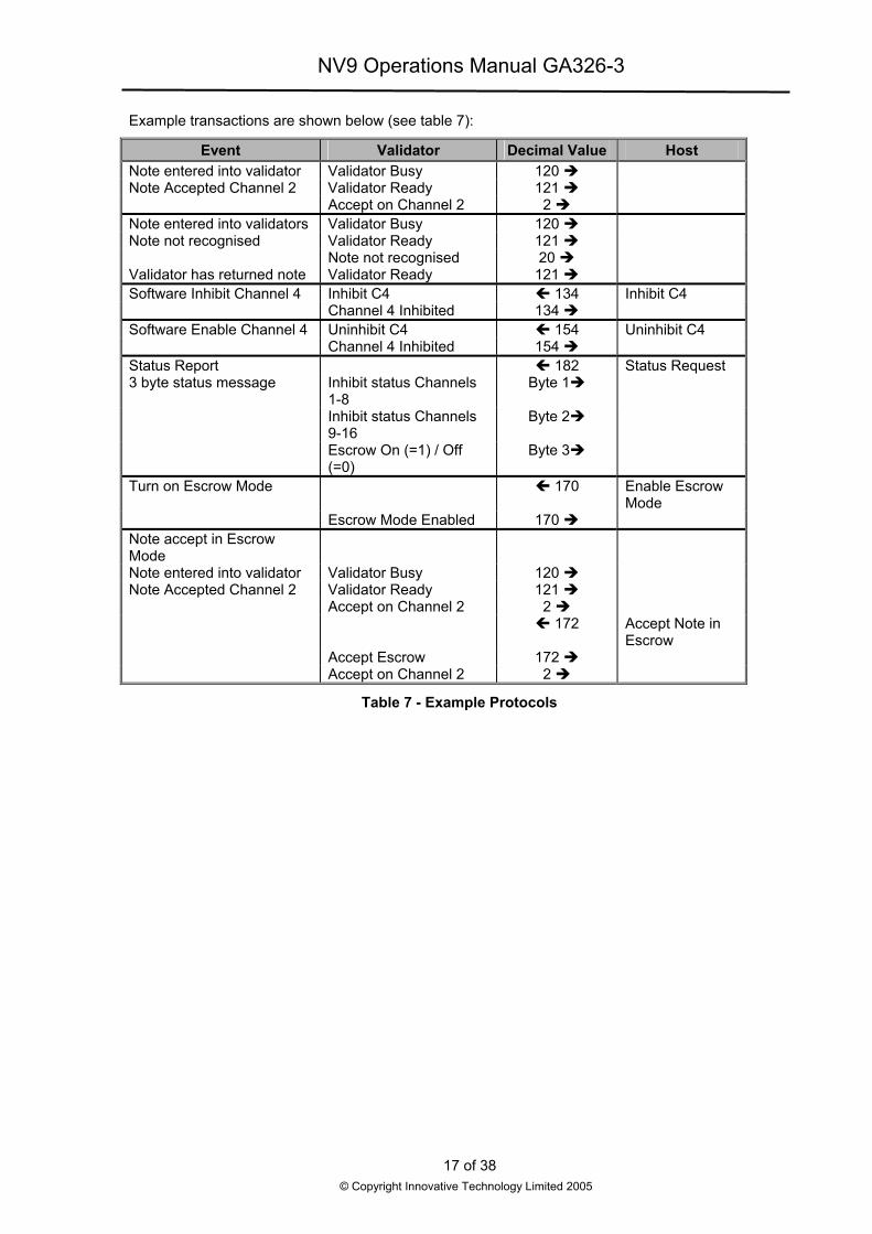
Example transactions are shown below (see table 7):
Event Validator Decimal Value Host Note entered into validator Validator Busy 120 Note Accepted Channel 2 Validator Ready 121 Accept on Channel 2 2 Note entered into validators Validator Busy 120 Note not recognised Validator Ready 121 Note not recognised 20 Validator has returned note Validator Ready 121 Software Inhibit Channel 4 Inhibit C4 134 Inhibit C4 Channel 4 Inhibited 134 Software Enable Channel 4 Uninhibit C4 154 Uninhibit C4 Channel 4 Inhibited 154 Status Report 182 Status Request 3 byte status message Inhibit status Channels
1-8 Byte 1
Inhibit status Channels 9-16
Byte 2
Escrow On (=1) / Off (=0)
Byte 3
Turn on Escrow Mode 170 Enable Escrow Mode
Escrow Mode Enabled 170 Note accept in Escrow Mode
Note entered into validator Validator Busy 120 Note Accepted Channel 2 Validator Ready 121 Accept on Channel 2 2 172 Accept Note in
Escrow Accept Escrow 172 Accept on Channel 2 2
Table 7 - Example Protocols
17 of 38
© Copyright Innovative Technology Limited 2005

NV9 Operations Manual GA326-3
7.5 Smiley® Secure Protocol - SSP Note: Please refer to the Smiley® Secure Protocol (SSP) Specification ITL Drawing GA 138 on the web site
for full details of the SSP protocol.
To use SSP mode DIPswitch 3 must be set up and DIPswitch 4 must be set down.
SSP is a secure serial interface specifically designed to address the problems experienced by cash handling systems in gaming machines. Problems such as acceptor swapping, reprogramming acceptors and line tapping are all addressed. This interface is recommended for all new designs.
The interface uses a master slave model, the host machine is the master and the peripherals (note acceptor, coin acceptor or coin hopper) are the slaves.
Data transfer is over a multi-drop bus using clock asynchronous serial transmission with simple open collector drivers. The integrity of data transfers is ensured through the use of 16 bit CRC checksums on all packets.
Each SSP device of a particular type has a unique serial number; this number is used to validate each device in the direction of credit transfer before transactions can take place.
Commands are currently provided for coin acceptors, note acceptors and coin hoppers. All current features of these devices are supported.
Features:
• Serial control of Note / Coin Validators and Hoppers
• 4 wire (Tx, Rx, +V, Gnd) system
• RS232 (TTL) - open collector driver
• High Speed 9600 Baud Rate
• 16 bit CRC error checking
• Data Transfer Mode
Benefits:
• Proven in the field
• Simple and low cost interfacing of transaction peripherals.
• High security control of payout peripherals.
• Defence against surrogate validator fraud.
• Straightforward integration into host machines.
• Remote programming of transaction peripherals
• Open standard for universal use.
For detailed information and full protocol specification please refer to SSP Specification ITL Drawing GA 138, this is available from the ITL website www.innovative-technology.co.uk. To help in the software implementation of the SSP, ITL can provide sample C Code, DLL controls and Visual Basic applications on request. Please contact [email protected].
18 of 38
© Copyright Innovative Technology Limited 2005

NV9 Operations Manual GA326-3
7.6 Multi-Drop Bus / Internal Communications Protocol (IF5) – MDB To use the MDB mode an IF5 interface box must be fitted to the NV9 Validator and DIPswitches 3 & 4 must both be set up, with the MDB option of the interface firmware loaded into the NV9.
Note: Please refer to the Multi-Drop Bus specification for the suggested current drive circuits
available.
The NV9 supports the MDB protocol version 1, level 1
For detailed information and full protocol specification please refer to www.nama.org
MDB defines a serial bus interface used in electrically controlled vending machines (see figure 6). This is a 9600 Baud Master-Slave system where the NV9 banknote validator is a slave to a master controller. A master has the capability of communicating with 32 peripherals or slaves. The master is defined as the Vending Machine Controller (VMC).
e
Figure 6 – MDB Opto Isola
The NV9 banknote Validators have a unique address – 001detect presence of the NV9 Validators or get information on
The Validators will respond when asked for activity with an a specific reply, depending on its current status. Bus crashepolled only by the VMC.
The international country code must be set for the country international telephone code for that country. The code is re
For the USA the country code is 00 01
For Great Britain the code is 00 44
The scaling factor must also be specified for each Validatorby this number.
• This number would be set to 100 (Hex 64
• The number would be set to 1000 (Hex 03
• The number of decimal places must also
• The number would be set to 2 for Euro or
• The number would be set to 3 for Roman
Adopting the numbers above:
• £5 would be displayed as 5.00
• £10 would be displayed as 10.00
19© Copyright Innovative
NV9 MDB Slav
Transmit
Receive
ted Input / Output circuits
10XXX binary (30H). The VMC polls the bus to the current status of the Validators.
acknowledgment, a negative acknowledgment or s are avoided as the Validators respond to being
in which the Validators will be operating. This is the presented as two bytes
. All accepted note values must be evenly divisible
) for the Euro or Great Britain.
E8) for Romania.
be programmed for each Validator
USA
ia
of 38 Technology Limited 2005

NV9 Operations Manual GA326-3
• $1 would be displayed as 1.00
• 1K Romania would be displayed as 1.000
7.7 CCTalk Protocol – CCT The NV9 supports the CCTalk serial protocol for easy interfacing with host machines that support this protocol.
To use CCTalk mode (as in Binary mode etc) set DIPswitches 3 and 4 in the Up position to select ‘Special’ mode on the validator.
The NV9 must have the CCTalk software loaded using the ‘‘advanced’’ option on the Currency manager program.
Pin out connections on NV9 for CCTalk are shown below (see figure 7) looking at the connection pins on the NV9 interface connector.
Notes: For detailed information and full protocol specification please refer to www.cctalk.org
Figure 7 - CCTalk Connection Pins on the NV9
The default encryption key will be set to the key code printed on the label on the NV9. If the key is changed to a new stored key by the host machine, the key can be reset to the default by the following the steps below.
1. Power off NV9.
2. Set all 4 DIPswitches to the Up position.
3. Apply power (no CCTalk comms).
4. Red LED will now be flashing.
5. Set DIPswitches 1 and 2 down.
The code is now reset.
20 of 38
© Copyright Innovative Technology Limited 2005

NV9 Operations Manual GA326-3
7.8 Extended Interface / USA Serial – NIS The USA Serial interface is a non-isolated interface serial communications protocol.
There is a single output DATA line from the NV9. There are three control lines, two from the controller ‘’ACCEPT ENABLE’’ and ‘’SEND’’ and one from the Validators IRQ (INTERRUPT) (see table 8).
Caution:
Please note that the NV9 is required to operate on a +12volt DC power supply.
The NV9 ground must be connected to the ground of the control system.
For further details on this protocol please refer to the Series 2000 Interface manual (reference number 20105-002850046-PS).
Connection Details:
Signal NV9 12v 15 0v 16
ACCEPT ENABLE 6 SEND 7
IRQ (INTERRUPT) 2 DATA 1
OUT_OF_SERVICE 3
Table 8 - Extended Interface USA Serial
21 of 38
© Copyright Innovative Technology Limited 2005
NV9 Operations Manual GA326-3
8 Updating Currency and Firmware Note: Validators are supplied already programmed from the factory. Please skip this section unless the
validators need to be re-programmed with a new note or currency.
The NV9 Validator can only be re-programmed using the ITL BNV download manager 2.9.7 or greater or by cloning from a master unit.
8.1 ITL BNV Download Manager To use the ITL BNV download manager software, which is supplied with a range of currencies. The system will require you to be running a PC Windows 95/98/NT™2000 or XP Professional, Pentium™ (© Microsoft and Intel).
A list of currently supported currencies is maintained on our web site, and new releases can be downloaded from www.innovative-technology.co.uk. Further details are available from [email protected]
How to register for the first time log in, please refer to Appendix D.
8.2 NV9 – NV9 Copy (Cloning) Overview
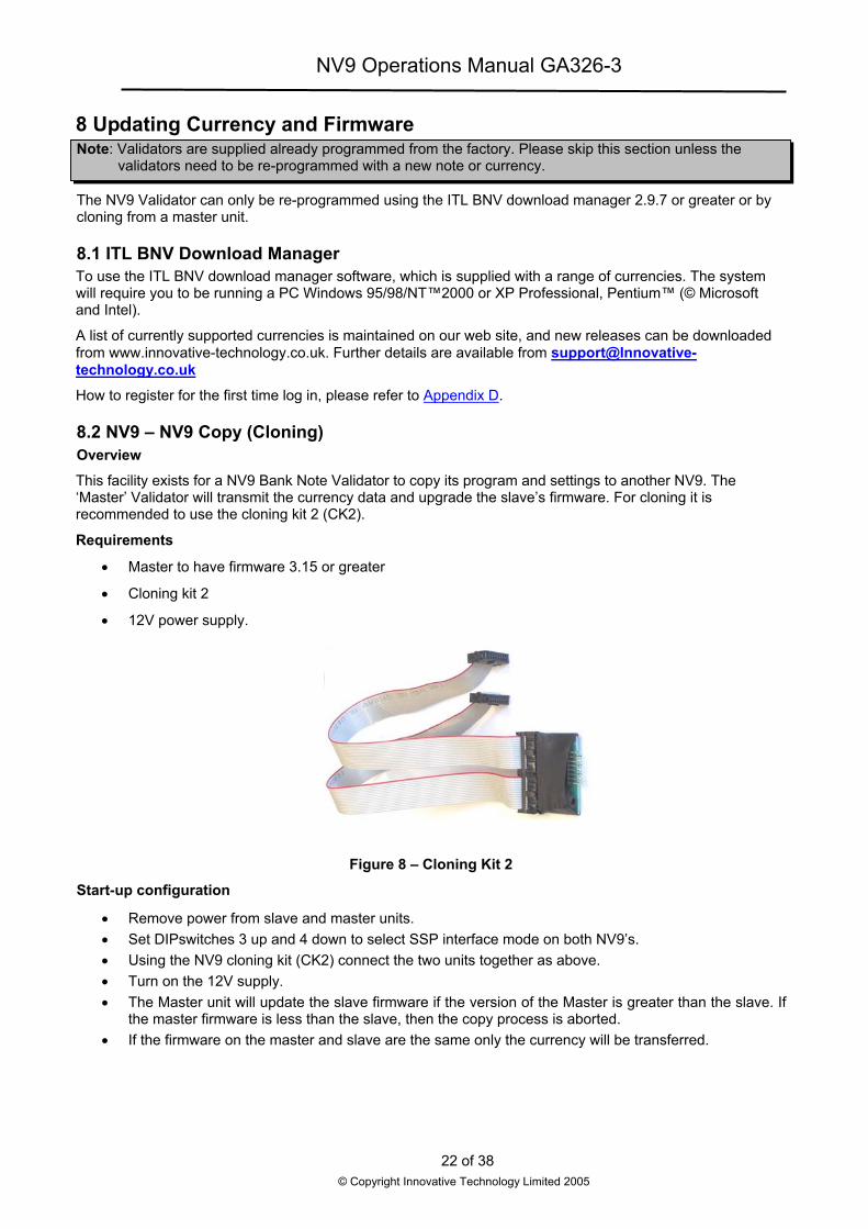
This facility exists for a NV9 Bank Note Validator to copy its program and settings to another NV9. The ‘Master’ Validator will transmit the currency data and upgrade the slave’s firmware. For cloning it is recommended to use the cloning kit 2 (CK2).
Requirements
• Master to have firmware 3.15 or greater
• Cloning kit 2
• 12V power supply.
Figure 8 – Cloning Kit 2
Start-up configuration
• Remove power from slave and master units. • Set DIPswitches 3 up and 4 down to select SSP interface mode on both NV9’s. • Using the NV9 cloning kit (CK2) connect the two units together as above. • Turn on the 12V supply. • The Master unit will update the slave firmware if the version of the Master is greater than the slave. If
the master firmware is less than the slave, then the copy process is aborted. • If the firmware on the master and slave are the same only the currency will be transferred.
22 of 38
© Copyright Innovative Technology Limited 2005

NV9 Operations Manual GA326-3
8.3:NV9 – NV9 copy process.
• Connect the NV9 to the master slave using CK2 and 12V power supply
• The Master unit will flash the RED and GREEN LED’s if the connector is configured correctly.
• RED and GREEN LED’s on the master flash together – attempting to communicate with Slave.
• RED and GREEN LED’s on master flash alternately - communication established, master waiting for Slave to reset.
• If communication has been established and the Slave has reset then the Master will read the Slave firmware version and decide on next action.
• If the Slave firmware version is not compatible with master: Master RED and GREEN LED’s will flash alternately at 1-second rate. No further copy action will take place.
• If slave firmware version is greater than master: Master RED and GREEN LED’s will flash alternately at 1 second rate. No further copy action will take place.
• If Slave firmware version is same as Master then Master will start to copy currency data to Slave.
• If Slave firmware version is less than master then master will start to copy firmware data to Slave.
Firmware copy:
Caution: If master RED LED changes to slow blink (1 per second) then communication has been lost and copying should be restarted from beginning.
• Master RED LED will blink rapidly during firmware copy (the LED will pause from time to time).
• When the firmware copy is complete, the Slave will reset and Master unit will wait to re-establish communications. (LED flashes as at first stage power-up).
• When slave is ready, master will initiate currency data copy.
Currency copy:
Caution: If master RED LED changed to slow blink (1 per second) then communication has been lost and copying should be restarted from beginning.
• Master GREEN LED will blink rapidly during the currency copy process and the LED will pause from time to time.
• When currency copy is complete, Master will show GREEN and RED LED’s continuously and slave will reset.
• NV9 – NV9 copy is now complete.
23 of 38
© Copyright Innovative Technology Limited 2005

NV9 Operations Manual GA326-3
9: Mechanical Installation The NV9 validators can be supplied with either of the following bezels, (see figure 9):
Vertical Down Snout Bezel PA191Horizontal Bezel PA189 Vertical Up Snout Bezel PA190Vertical Up Bezel PA256
Figure 9 - NV9 Bezels
9.1:Changing or removing the bezels
Caution: Always make sure that both the locking arms have fully located in to prevent damage.
Push both of the red locking arms so that they disengage from the bezel sides. The bezel may then be unhooked from the 6 locating points, (see figure 10). To refit push the bezel onto the six locating points (3 each side). The red locking arms will spring back to secure the bezel
Locating Pin
L
9.2:Changing orThe NV9 validators c
• 300 Note Cli
• 300 Note Slid
• 600 Note Cli
• 600 Note Slid
• 300 Note Locwith Baton L
Bezel
Figure 10 - Bezel and Validator Removal
Red Locking Arm
ocating Pins
removing cash boxes an also be supplied with the various cash box options, (see figure 11).
Slide In Cash Box Clip On Cash Box
Figure 11 - Clip On and Slide in Cash Boxes
p (part no PA185) on for the vertical bezel options only.
e in (part no PA192) for both the horizontal and vertical bezel options.
p on (part no PA193) for the vertical bezel options only.
e in (part no PA194) both the horizontal and vertical bezel options.
kable for the horizontal bezel option only (part no PA186). (Lock is not supplied – use ock type 6086-00KAL06 with supplied cam)
24 of 38© Copyright Innovative Technology Limited 2005

NV9 Operations Manual GA326-3
10 Routine Maintenance The NV9 Validator has been designed to minimise any performance variation over time. Much of this is achieved by careful hardware and software design.
However, depending upon the environment the NV9 may at some time require cleaning, belt changing or note path clearing.
10.1 Cleaning CAUTION: DO NOT USE SOLVENT BASED CLEANERS SUCH AS ALCOHOL, PETROL, METHYLATED
SPIRITS, WHITE SPIRIT or PCB CLEANER. THIS WILL RESULT IN PERMANENT DAMAGE TO THE VALIDATOR, ALWAYS USE A MILD DETERGENT.
To clean, slide the red release catch on the end of the NV9 Validator to open the note path. The note path and lozenge are now exposed for cleaning.
Carefully wipe the surfaces with a soft lint free cloth that has been dampened with a water and mild detergent solution (i.e. household washing up liquid). Take particular care around all the sensor lenses (see figure 12), ensuring they are clean and dry.
Caution When cleaning the ‘’recessed’’ Front Sensors, use a small soft brush or cotton wool bud.
If a lens has become badly scratched do not attempt to polish it. Contact ITL for further advise, as there may be damage to the optical properties of the lens.Figure 12 - NV9 Sensors
F
Red Release Catch
Optical Sensor
ront Sensors
r
25 of 38© Copyright Innovative Technology Limite
Optical Senso
Start Sensor
Rear Sensor
d 2005

NV9 Operations Manual GA326-3
10.2 Note Path Debris Clearing / Belt Changing To access the note path and lozenge, slide the red release catch on the end of the NV9 Validator and lift to open. Push the lozenge release catch and lift; the note path and lozenge are now exposed for maintenance (see figure 13).
Lozenge
Deb
Exa
Cardamarou
Che
Bel
Withcab
Remwhe
Lozenge ReleaseCatch
h
ris
min
efupend
ck
t Ch
thle a
ovels
Note Pat
Figure 13 - NV9 Note Path and Lozenge Access
Clearing
e the note paths, lozenge and note stacker for any dirt or debris.
lly clear and wipe the surfaces of the note paths and lozenge with a soft lint free clothned with a water and mild detergent solution (i.e. household washing up liquid.). Tak all the sensor lenses (see figure 12), ensuring they are clean and dry.
that the note stacker and cash box spring plate are not jammed.
anging
e NV9 lozenge exposed (see figure 13) carefully unplug the bottom connector of thessembly’’ from the lozenge.
e and place the lozenge on a clean dry surface and remove the belts, sliding them o first. Replace the belts using the reverse procedure from the above.
26 of 38
© Copyright Innovative Technology Limited 2005
Red Release Catch
Top to Bottom Cable Assembly
Belts
Note StackerPusher Plate
Cash Box Spring Plate
that has been e particular care
‘’top to bottom
ff the smallest
NV9 Operations Manual GA326-3
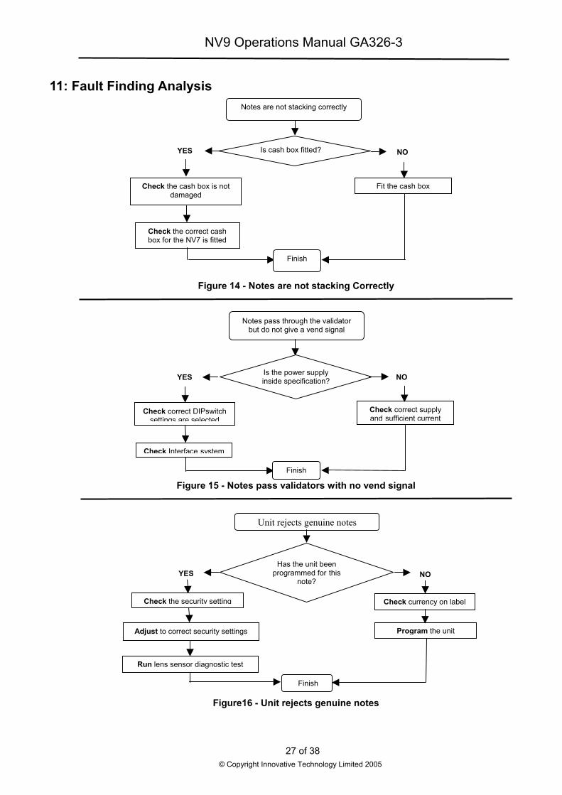
11: Fault Finding Analysis
Finish
Check the correct cash box for the NV7 is fitted
Check the cash box is not damaged
Fit the cash box
NO YES Is cash box fitted?
Notes are not stacking correctly
Figure 14 - Notes are not stacking Correctly
Figure 15 - Notes pass validators with no vend signal
Notes pass through the validator but do not give a vend signal
Is the power supply inside specification?YES NO
Check correct supply and sufficient current
Check correct DIPswitch settings are selected
Check Interface system
Finish
Unit rejects genuine notes
Has the unit beenprogrammed for this
note?NO
Check currency on labelCheck the security setting
YES
Adjust to correct security settings
Run lens sensor diagnostic test
Program the unit
Finish
Figure16 - Unit rejects genuine notes
27 of 38
© Copyright Innovative Technology Limited 2005
NV9 Operations Manual GA326-3
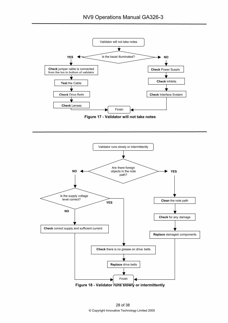
Is the bezel illuminated?S
Validator will not take notes
O
Check jumpfrom the top
Tes
Che
Ch
Check correct s
Is thlev
N
YE
Finish
er cable is connected to bottom of validator
Check P
Check In
t the Cable
ck Drive Belts
Che
eck Lenses
Figure 17 - Validator will not take notes
Figure 18 - Validator runs slowly or intermittentFinish
Replace drive belts
Check there is no grease on drive belts
Repla
Ch
upply and sufficient current
C
Are there foreign objects in the note
path?
e supply voltage el correct?
NO
Validator runs slowly or intermittently
YES
O
28 of 38© Copyright Innovative Technology Limited 2005
N
ower Supply
terface System
ck inhibits
ly
ce damaged components
eck for any damage
lean the note path
YES

NV9 Operations Manual GA326-3
12 Support Tools The following support tools are available for use with the NV9 Bank Note Validator:
1. ITL BNV download manager Software.
2. Downloads from the Innovative Technology Ltd website: www.innovative-technology.co.uk
3. E-mail Support [email protected].
12.1 PC Currency Programming Software (ITL BNV Download Manager) The ITL BNV download manager software offers the following functions:
• Program the Validator by downloading pre-prepared currency data via the serial communications link using the DA1 kit or DA2 kit using the USB link.
• Check the firmware version and currency set already loaded on an NV9 unit.
• Adjust the channel and pulse configuration on a pre-programmed NV9 to your own requirements.
• Download a new version of firmware onto the NV9.
• Use diagnostic functions to check Validators operation (firmware version 3.15 and greater only).
The software will run on an IBM compatible Personal Computer with Pentium™ processor or equivalent and requires a DA1 kit fitted to the serial port or DA2 kit fitted to the USB port depending on the operating system that you are using (see Appendix C).
12.2 Internet Website support The Innovative Technology Ltd website provides the means to download new and updated currency sets and new versions of firmware for the NV9. Visit www.innovative-technology.co.uk to register your user name and to access the password for further details, updates and technical bulletins, which are also made available.
How to register for the first time log in, please refer to Appendix D.
12.3 E-mail Support If the data you require is not available over the Internet Innovative Technology supports an e-mail system to help customers with unusual requirements. The address is [email protected]
29 of 38
© Copyright Innovative Technology Limited 2005
NV9 Operations Manual GA326-3
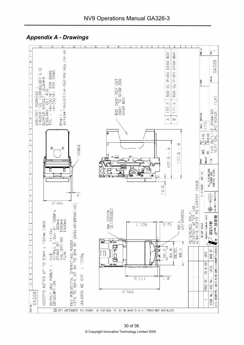
Appendix A - Drawings
30 of 38© Copyright Innovative Technology Limited 2005

NV9 Operations Manual GA326-3
31 of 38
© Copyright Innovative Technology Limited 2005

NV9 Operations Manual GA326-3
32 of 38
© Copyright Innovative Technology Limited 2005

NV9 Operations Manual GA326-3
33 of 38
© Copyright Innovative Technology Limited 2005

NV9 Operations Manual GA326-3
34 of 38
© Copyright Innovative Technology Limited 2005

NV9 Operations Manual GA326-3
Appendix B - ESCROW Control The NV9 has a single note escrow facility (pin 10). This allows the Validator to hold onto the note once accepted, and then only stack the note in the cash box when the host machine confirms that the Vend operation has been completed. If no confirmation of the Vend is received then the note will be returned to the customer after 30 seconds, (see figure 19).
30sec Max
100ms100ms
Do not wait more than 30 seconds for the 2nd vend confirmation signal Vend Signal
Escrow held low
Escrow Accepting
n
If thnote
Thetimea no
In thNV9
Not
Escrow Rejectio
Figure 19 - Escrow
Vend Signal
Inhibit
e host machine itself aborts the transa is returned immediately. The sequen
1. Pin 10 held low awaiting note i
2. Note inserted. Validator issues
3. The host machine initiates ven
4. The host machine sets pin 10 hseconds the Validator will retur
5. The Validator issues a 100ms indicate final acceptance of theindicates the customer has for
6. The vend process is completed
7. The host machine sets pin 10 l
host machine can force the return of t before the end of the 30 second timete reject.
e event of a note being forcibly remov will go out of service for 45 seconds.
e: Escrow Control (SSP mode): Escto SSP Specification GA138 availab
© Copyrigh
Timing Diagram for Parallel Vends
Inhibit rejection can be at any time during the 30 second decision period after completion of the vend
ction by setting the corresponding inhibit input high on pin 10, the ce of operations is as follows:
nsertion.
a 100ms pulse on the appropriate channel.
d process.
igh to indicate that it wants the note. If this is not done within 30 n the note.
pulse on the appropriate channel after pin 10 going high to note. If the signal has not been received within 30 seconds it
cibly retrieved the note and the vend will be aborted.
.
ow in expectation of the next vend.
he note to the customer by setting the inhibit line high, at any -out. For channels above 4, setting all the inhibits high will cause
ed from the mouth of the NV9 during the 30 second interval, the
row is also possible using the SSP serial Interface. Please refer le on the website www.innovative-technology.co.uk.
35 of 38t Innovative Technology Limited 2005

NV9 Operations Manual GA326-3
Appendix C - interface Tools DA1 - DA2 The DA1/2 Kits are designed for the following:
• Connecting of ITL note validators to a PC to upgrade note data and firmware.
• Testing of NV9 note validators independently of the host machine to confirm the validator is working but the host machine may be inhibiting some of the channels.
The DA1 and DA2 Kit comprise of the following components:
DA1 DA2 DA1 adapter board (PA167) DA2 adapter board
NV9 Adapter to Validator cable (C USB type-A to Type-B cable ITL Support CD-ROM for DA1 ITL Support CD-ROM for DA2
Power Cable DA2 to NV9 cable Installation Guide Power Cable
Installation Guide Connecting a DA1 to a validator and PC
If you are using Windows 95/98/NT/XP™, Pentium™ (© Microsoft and Intel) operating systems connect the DA1 to the validator as shown below (see figure 1), using the 16-way to 5-way connector. The 3.5mm jack plug and 2 banana plugs are used to supply power to the DA1. Connect +12 volts to the red banana plug and GND (0V) to the black plug. Plug the 9-way D-type connector into the serial port of the PC and note of the number of the port, as this will be needed later for configuring the software. Once the connections have been made install the appropriate software for the validator you are using.
Figure 1 - Connecting DA1 to a NV9 and PC for upgrading
Connecting a DA2 to a validator and PC If you are using Windows Pentium™ (© Microsoft and Intel) 98, 98SE, 2000, XP Home or XP Professional operating systems, connect the DA2 to the validator as shown below (see figure 2), using NV9 TO DA2 connector. The 3.5mm jack plug and 2 banana plugs are used to supply power to the DA2. Connect +12 volts to the red banana plug and GND (0V) to the black plug. Plug the USB type Connector into the USB port of the PC. Once the connections have been made install the appropriate software for the validator you are using.
+ 12V DC
FSoftware Installation To install the software tinstallation menu will apwish to use. Follow the using the software you Please contact suppor
PC USB Port
igure 2 - Connecting DA2 to a NV9 and P
o upgrade datasets and firmware, insert thepear, select the product that you wish to doonscreen instruction to complete the installahave installed can by found in the online [email protected], if you req
36 of 38© Copyright Innovative Technology Limited
Validator
C for upgrading
CDROM into the PC drive. An wnload, and select the software you tion. Instructions for configuring and
lp for that software. uire further assistance.
2005

NV9 Operations Manual GA326-3
Appendix D – Website Registration
Please move mouse cursor overthe „support“ button and click on „Currency Downloads“!
, registered!“here
If you are„please
notclick
If you are already registered , pleaseuser
typename
in your and
self - given password !
37 of 38
© Copyright Innovative Technology Limited 2005

NV9 Operations Manual GA326-3
38 of 38
© Copyright Innovative Technology Limited 2005
Please enter yourcompany name here!
For your registration we need a valid e-mail adress.
Here you can choose a user namewhich you will need to log in.
For a job description you can selectone of the listed occupations.
Please enter you self-given password here!
After you filled in all informations, please clickon „Register Details“! Approx. 10 mins later youraccount will be ready for your log in.