Innovative geophysical technology for prognosing location ...
35
Gordon Stove Co-Founder & Managing Director, Adrok Ltd 21 st January 2010 Finding Petroleum Conference, London Innovative geophysical technology for prognosing location of subsurface hydrocarbons before drilling Spectrometric Mapping Solutions
Transcript of Innovative geophysical technology for prognosing location ...
Commercial-In-Confidence© Adrok Ltd 2009 1
Gordon Stove
Co-Founder & Managing Director, Adrok Ltd
21st January 2010
Finding Petroleum Conference, London
Innovative geophysical technology for prognosinglocation of subsurface hydrocarbons before drilling
Spectrometric Mapping Solutions

Commercial-In-Confidence© Adrok Ltd 2009 2
Objectives• Introduce new geophysical technology
- Adrok® Scanner
• Present Case Studies as field proof
– Onshore, North Africa (new gas discovery)
• Adrok Energy Services to oil companies
• Summary

Commercial-In-Confidence© Adrok Ltd 2009 3
Introduction of the new geophysical technology for finding petroleum:
Adrok® Scanner

Commercial-In-Confidence© Adrok Ltd 2009 4
• Performs functions of seismic and of drilling and logging exploration wells
• Uses Electromagnetic (EM) energy - speed of light!
• EM techniques are already being used in oil & gas industry
• Adrok has now extended the technology to oil and gas exploration and are able to offer their services
Totally new technology that …
Commercial-In-Confidence© Adrok Ltd 2009 5
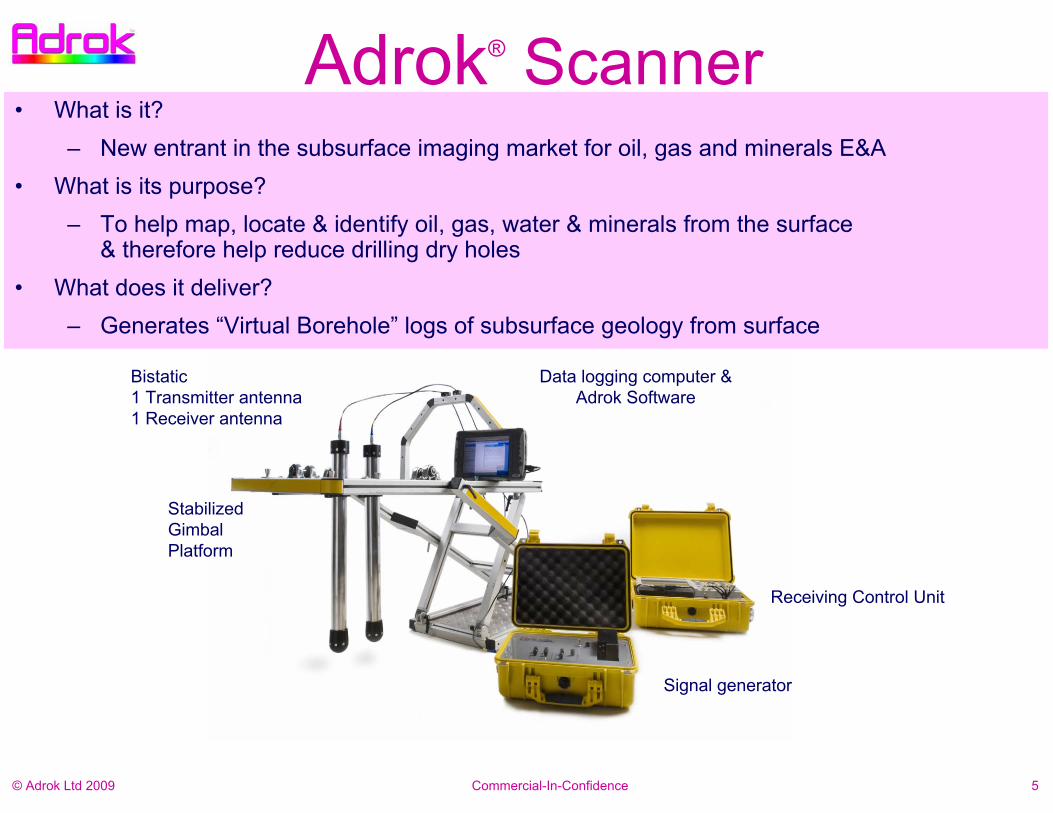
Data logging computer & Adrok Software
Receiving Control Unit
Bistatic1 Transmitter antenna1 Receiver antenna
Stabilized GimbalPlatform
Signal generator
Adrok® Scanner• What is it?
– New entrant in the subsurface imaging market for oil, gas and minerals E&A • What is its purpose?
– To help map, locate & identify oil, gas, water & minerals from the surface & therefore help reduce drilling dry holes
• What does it deliver? – Generates “Virtual Borehole” logs of subsurface geology from surface

Commercial-In-Confidence© Adrok Ltd 2009 6
Field Deployment

Commercial-In-Confidence© Adrok Ltd 2009 7
• Adrok Scanner Illuminates the ground by Transmitting & Receiving Invisible Lased Light beams of Electromagnetic energy– Pulsed – Coherent (over a narrow band of
frequencies)– Collimated (cylindrical shape) – Radiowaves, Microwaves– Resonant frequencies– Minimal beam dispersion
• Penetrates from ground surface to proven depths of up to 4km
• Typecasts of materials• In-house• In field
Subsurface Scanning Process
-1km
-40m
-4km
Tx
0m
Rx1 Rx2 Rx3
1m
2m
10m
30m
Commercial-In-Confidence© Adrok Ltd 2009 8
• Adrok Scanner measures:
– Dielectric Permittivity
– Basic facts of spectroscopy
– Resonant behaviours of atoms and molecules
Measurements

Commercial-In-Confidence© Adrok Ltd 2009 9
• Adrok has developed five complimentary sets of procedures for subsurface measurements of:
– Rock properties– Range– Resonance– Reflectivity– Recognition ..… the “5Rs”
“5R” Technical Process

Commercial-In-Confidence© Adrok Ltd 2009 10
Rock Properties
• Adrok Scanner measures the dielectric permittivity of rocks:– in the ground in situ – or in laboratory / core store
• From the dielectric measurements, we produce velocities, dielectric constants, and depth measurements from the surface and between subsurface layers.
• Moisture content of rocks • Hydrocarbon concentrations in rocks

Commercial-In-Confidence© Adrok Ltd 2009 11
• Accurate depth measurement – Subsurface responses are referenced to 3 time
stamped levels in z-depth plane 1. Transmitter datum from sensor aperture 2. Surface level datum3. Direct Wave datum (between Transmitter &
Receiver) for any given separation.– Nanosecond time range
• Interlayer Velocities of beam through media are related back to speed of light
• Deep penetration– Standing waves of energy sent into the ground – Minimal attenuation & dispersion
• Because beam is lased & operates over a limited range of frequencies
• Directional beam– Beam can be controlled to look obliquely through
ground
Range

Commercial-In-Confidence© Adrok Ltd 2009 12
Resonance• Beam sent into the ground is resonating (the signal rings in the ground), this has two effects:
1. It can help beam propagation (Ranging) 2. Resonance within layers of uniform dielectrics helps illuminate boundaries
Material #1
Material #2
Transmitted beam
travelling toward
material under observation
Reflected beam
travelling from material
to receiver
Reflections
Energy transfer through material
Energy at
vibrates at different
frequencies & phase angles
different resonances,

Commercial-In-Confidence© Adrok Ltd 2009 13
Reflectivity• Reflectivity measurements helps identify subsurface boundaries & one rock type from another • At dielectric boundaries in the ground, Reflectivity Coefficients are calculated from the
amplitude response of the beam• Different reflectivity responses for different rock types:
– Fine grained rocks give more reflectivity response than coarse grained rocks– Pure Mudstone is highly reflective, but Sandy Mudstone has absorption & reflection peaks
Sandy Mudstone Coal
RF=0.97RF=1.00 & 0.99
RF=0.48
RF=0.75

Commercial-In-Confidence© Adrok Ltd 2009 14
Recognition• Adrok Scanner is an imaging spectrometer• Reference databases of Adrok signatures
developed by Spectral Analysis (energy, frequency)
• Expert Systems developed to help classify material signatures by different statistical methods.

Commercial-In-Confidence© Adrok Ltd 2009 15
Dr G. Colin Stove - serial-inventor
•Among many other senior academic and government roles Dr Stove was part of the team within the Macaulay Institute that developed a unique machine-vision system (called MAPIPS and GEMS) for automated photogrammetric mapping & intelligent classification of terrain and subsurface stratigraphy from ground, aerial and satellite or spaceborne platforms.
•ESA, NASA & NATO Principal Investigator
•Inventor of scientific principles of Atomic Dielectric Resonance (ADR)
•ADR is patented and represents a carefully engineered advance of this work which has led to an acknowledged change to certain laws of physics.
•Exclusive licence to Adrok to commercialise ADR
+30 Years of Research!

Commercial-In-Confidence© Adrok Ltd 2009 16
• Dielectric Resonance physics is widely accepted in many civil engineering, pharmaceutical, astrophysical market applications, e.g., used by:
– Agilent Technologies,– MIT– NASA– Imperial College, London– De Montfort University – Material Sensing & Instrumentation Inc
• EM techniques are widely used in Oil & Gas industry: – Subsurface: CSEM, MTEM (Exxon Mobil, Shell, EMGS, PGS, Statoil,
OHM, Rocksource)– Downhole: EM resistivity (Halliburton, Schlumberger)
& dielectrics (Schlumberger)
Scientific Reference Points

Commercial-In-Confidence© Adrok Ltd 2009 17
Technology Adoption Cycle
After Geoffrey A. Moore (1999)

Commercial-In-Confidence© Adrok Ltd 2009 18
Some Early O&G Users of Adrok Scanner

Commercial-In-Confidence© Adrok Ltd 2009 19
Technology Summary
• Adrok’s technology provides:
1. Stratigraphy (like seismic)
2. Detailed information on rock characteristics (like well logs)
3. Actual rock petrography (like cores)

Commercial-In-Confidence© Adrok Ltd 2009 20
Case Study – field proofGas Prospect in North Africa

Commercial-In-Confidence© Adrok Ltd 2009 21
Onshore N. Africa, thin gas horizons
• Survey Area located in North Africa
• Adrok trained on 3 drilled well locations (for gas & sedimentary rock layer signatures)
• Surface terrain comprised low lying hills and scrubland
• Tortonian sand reservoirs
• Gas horizons were very thin
• ranging from 0.5m to 12m
• Prospect site was 42km offset from training well location
• The results of the Adrok survey were compared to the actual drilling results (Adrok presented results before drilling commenced).
• Adrok produced Virtual borehole log charts
• No HSE accidents

Commercial-In-Confidence© Adrok Ltd 2009 22
Composite Log comparing ADR Scanner results with Seismic AVO, & down-hole tools showed that gas layer were more accurately prognosed by ADR (red dots) than by seismic and AVO (green dots).

Commercial-In-Confidence© Adrok Ltd 2009 23
Case History 2 Client Conclusions
the well

Commercial-In-Confidence© Adrok Ltd 2009 24
Geophysical Survey Services

Commercial-In-Confidence© Adrok Ltd 2009 25
3. On-site Survey Data Acquisition
2. Training for geological signatures
1. Pre-survey field modeling
4. Data Processing & Interpretation
5. Analysis & results Delivery
6. Integration to other data sets
Adrok Survey Process
Adrok aims to provide useful subsurface measurements to help de-risk drilling programmes

Commercial-In-Confidence© Adrok Ltd 2009 26
Adrok’s fit with Oil Company’s WorkflowsExploration Phase Appraisal Phase Execution Phase Operation Phase
Dry Hole
Poss
ible
Com
mer
cial
Fie
ld
Geophysics Data (Seismic, EM,
Aero)
Evaluate Data
Geologic Model
Reservoir Simulations
Exploration Well
Define Field Development Plan
Seismic and/or EM Survey
Implement Field
Development Plan
Facility design
Facility Fabrication
Facility Installation
Development Drilling
Fina
l Inv
estm
ent D
ecis
ion
Field Production
Production
Exporting
Maintenance
Well intervention
Well Data
Geophysics Data
Production Data Extended Well Test
More Information needed
Appraisal Well(s)
ADROK Scan
ADROK Scan

Commercial-In-Confidence© Adrok Ltd 2009 27
Exploration Value Model
PROJECT MATURITY
Gen
erat
ive
(Pla
ys, L
eads
, Pr
ospe
cts) Geo
phys
ical
Sur
veys
/ Ex
plor
atio
n W
ells
Def
initi
on /
App
rais
al
F iel
d D
e vel
opm
ent
P la n
&
imp l
eme n
t ati o
n
Fie l
d Pr
oduc
tion
DISCOVERY
VALU
E
Risk
Value

Commercial-In-Confidence© Adrok Ltd 2009 28
Stages of Petroleum Field
ADROK Scan
ADROK Scan
ADROK Scan

Commercial-In-Confidence© Adrok Ltd 2009 29
Results
• Spectral ADR output (QAQC)
Simplifiedgraphicof chart
• Client Deliverable – virtual wellboresurvey chart

Commercial-In-Confidence© Adrok Ltd 2009 30
Field Survey Requirements• Transport for
– survey crew (minimum 4 person)– equipment (7 small cases – excess flight baggage)
• Access– 100 metres strip of clear space
• Representative training data– field drill site & drill log– core or rocks from field of interest
Commercial-In-Confidence© Adrok Ltd 2009 31
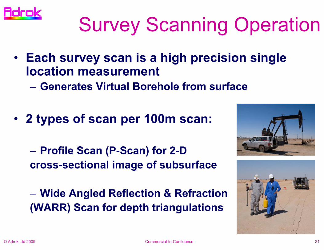
Survey Scanning Operation• Each survey scan is a high precision single
location measurement – Generates Virtual Borehole from surface
• 2 types of scan per 100m scan:
– Profile Scan (P-Scan) for 2-D cross-sectional image of subsurface
– Wide Angled Reflection & Refraction (WARR) Scan for depth triangulations

Commercial-In-Confidence© Adrok Ltd 2009 32
Advantages
• High confidence– output numerical interpretation
• Simple deployment– Fast, compact, portable equipment
• Low cost– Compared with competing technologies
• Seismic / EM resistivity• Aero-mag/gravity• Wildcat Drilling

Commercial-In-Confidence© Adrok Ltd 2009 33
Performance
• Depth penetration 4km now proven• Depth Resolution > 1m• Physical size Man-portable• Physical endurance IP65 weatherproof• Power requirement 200 watts• Time to survey/50m 2 hours • Time to deliver result 3 days per survey point

Commercial-In-Confidence© Adrok Ltd 2009 34
Hydrocarbons & Minerals MappingNOW – ONSHORE & OFFSHORE (Virtual Boreholes)
• Appraisal • Field delineation and gross volumetrics• Infill drilling location identification and confirmation• 2D structural surveying• Small scale exploration (point & shoot sites)
FUTURE• Large Scale Exploration – requires increased application database and
ADR sensor training to increase confidence levels• Reservoir monitoring and management – requires deployment of fixed
multiple sensors with lower unit cost base• Airborne surveys will require development and construction of stabilised
platform

Commercial-In-Confidence© Adrok Ltd 2009 35
Thank You
Gordon StoveManaging Director
Adrok49-1 West Bowling Green StreetEdinburghScotland, U.K.Tel: +44 131 555 6662Mobile: +44 7939 051 829
E-mail: [email protected]: www.adrokgroup.com