Innovative Energy-Absorbing Concept for Aircraft Cabin Interior
10
AST 2007, March 29-30, Hamburg, Germany INNOVATIVE ENERGY-ABSORBING CONCEPT FOR AIRCRAFT CABIN INTERIOR M. Pein 1* , D. Krause 1 , S. Heimbs 2 , P. Middendorf 3 1 Institute for Product Development and Mechanical Engineering Design, Hamburg University of Technology Denickestraße 17, 21073 Hamburg, Germany 2 EADS Innovation Works Neßpriel 1, 21129 Hamburg, Germany 3 EADS Innovation Works Willy-Messerschmitt-Straße, 85521 Ottobrunn, Germany [email protected] (e-mail address of lead author) Abstract An innovative concept for energy absorbers integrated in cabin components of commercial aircrafts is presented. The concept involves fibre-reinforced plastics as an energy-absorbing material of low weight, but leads to challenges in design and simulation. Because of the complex failure modes, extensive material testing was conducted, creating a knowledge-base for design, including design-guidelines. The simulation of the energy absorbers with the finite element code LS-DYNA has to consider non-physical input due to the complicated failure modes, which is discussed based on the used material model. The presented information is the output of a joint research project between Airbus Germany, EADS Innovation Works and the Hamburg University of Technology funded by the Department of Economy and Labour of Hamburg. 1 INTRODUCTION The aim of the development of lightweight energy-absorbing support structures for aircraft (A/C) cabins is to limit the loads acting on the cabin components (force limiters) and to maintain a safe area for passengers during dynamic load cases. For example, the overhead stowage compartments (OHSC, hatracks, Fig. 1) inside the A/C cabin are subjected to high loads during turbulences or hard landings. To prevent the detachment of the hatracks from the primary A/C structure force-limiting support structures were investigated to ensure the structural integrity of the hatrack and the A/C structure up to a certain level, depending on the energies involved.
Transcript of Innovative Energy-Absorbing Concept for Aircraft Cabin Interior

7/30/2019 Innovative Energy-Absorbing Concept for Aircraft Cabin Interior
http://slidepdf.com/reader/full/innovative-energy-absorbing-concept-for-aircraft-cabin-interior 1/10
AST 2007, March 29-30, Hamburg, Germany
INNOVATIVE ENERGY-ABSORBING CONCEPT FOR
AIRCRAFT CABIN INTERIOR
M. Pein1*
, D. Krause1, S. Heimbs
2, P. Middendorf
3
1Institute for Product Development and Mechanical Engineering Design,
Hamburg University of Technology
Denickestraße 17, 21073 Hamburg, Germany
2
EADS Innovation Works Neßpriel 1, 21129 Hamburg, Germany
3EADS Innovation Works
Willy-Messerschmitt-Straße, 85521 Ottobrunn, Germany
[email protected] (e-mail address of lead author)
AbstractAn innovative concept for energy absorbers integrated in cabin components of commercial
aircrafts is presented. The concept involves fibre-reinforced plastics as an energy-absorbingmaterial of low weight, but leads to challenges in design and simulation. Because of the
complex failure modes, extensive material testing was conducted, creating a knowledge-base
for design, including design-guidelines. The simulation of the energy absorbers with the finite
element code LS-DYNA has to consider non-physical input due to the complicated failure
modes, which is discussed based on the used material model. The presented information is
the output of a joint research project between Airbus Germany, EADS Innovation Works and
the Hamburg University of Technology funded by the Department of Economy and Labour
of Hamburg.
1 INTRODUCTION
The aim of the development of lightweight energy-absorbing support structures for
aircraft (A/C) cabins is to limit the loads acting on the cabin components (force
limiters) and to maintain a safe area for passengers during dynamic load cases. For
example, the overhead stowage compartments (OHSC, hatracks, Fig. 1) inside the
A/C cabin are subjected to high loads during turbulences or hard landings. To prevent
the detachment of the hatracks from the primary A/C structure force-limiting support
structures were investigated to ensure the structural integrity of the hatrack and the
A/C structure up to a certain level, depending on the energies involved.

7/30/2019 Innovative Energy-Absorbing Concept for Aircraft Cabin Interior
http://slidepdf.com/reader/full/innovative-energy-absorbing-concept-for-aircraft-cabin-interior 2/10
M. Pein*, D. Krause, S. Heimbs, P. Middendorf
2
Figure 1 – Showcase hatracks of common aircraft cabin interior
Because commercially available solutions for force-limiters do not fulfil the
specific A/C requirements with respect to weight and installation space, a joint
research project between Airbus Germany, EADS Innovation Works and the
Hamburg University of Technology was conducted in order to develop innovative
energy absorbers for A/C cabin components.
Today the applicable design rules of OHSC refer to static decelerations which
are used to calculate the forces inside the connecting support structures. Due to the
short duration of a crash, these design rules do not necessarily represent the transient
nature of the acting forces and decelerations. Therefore, an approach towards
dynamic load cases, as used for the certification of A/C seats, was investigated. Since
the load varies with time, force-limiters can be used to keep the maximum stress in
the composite sandwich structures of the hatracks under a defined level. The aim is to
develop force-limiting supports, which are capable of absorbing high amounts of
energy but have low weight, thus leading inevitably to the design of innovative
supports/attachments, which involve new energy-absorbing materials.
2 DEVELOPMENT OF AN INNOVATIVE ENERGY-ABSORBING
CONCEPT
The utilisation of force-limiters has two main advantages:
• Firstly, the supported OHSC has to be designed only up to the triggering force
of the force-limiter, including a fitting factor.
• Secondly, the primary A/C structure does not have to be designed up to the
forces with fixed supports, but only to the triggering force of the force-limiters.
Energy-absorbing supports for overhead stowage compartment Linear bearing
7/30/2019 Innovative Energy-Absorbing Concept for Aircraft Cabin Interior
http://slidepdf.com/reader/full/innovative-energy-absorbing-concept-for-aircraft-cabin-interior 3/10
AST 2007, March 29-30, Hamburg, Germany
3
Both effects allow a decrease of structural weight due to lower forces. In the
project, more than 10 different energy-absorbing materials with different support
concepts were analysed according to the defined boundary conditions, showing
promising results but requiring a bigger design space than conventional supports
[1],[2]. Based on patent application publication DE 199 26 085 [3], one concept was
found showing a high potential for implementation as a z-axis hatrack support (Fig. 2).
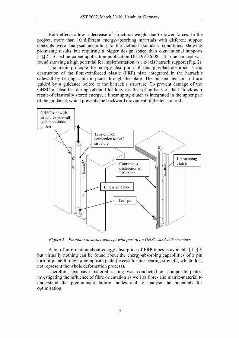
The main principle for energy-absorption of this pin/plate-absorber is the
destruction of the fibre-reinforced plastic (FRP) plate integrated in the hatrack’s
sidewall by tearing a pin in-plane through the plate. The pin and tension rod are
guided by a guidance bolted to the hatrack’s structure. To prevent damage of the
OHSC or absorber during rebound loading, i.e. the spring-back of the hatrack as a
result of elastically stored energy, a linear sprag clutch is integrated in the upper part
of the guidance, which prevents the backward movement of the tension rod.
Figure 2 – Pin/plate-absorber concept with part of an OHSC sandwich structure
A lot of information about energy absorption of FRP tubes is available [4]- [9]
but virtually nothing can be found about the energy-absorbing capabilities of a pin
torn in-plane through a composite plate (except for pin-bearing strength, which does
not represent the whole deformation process).
Therefore, extensive material testing was conducted on composite plates,
investigating the influence of fibre orientation as well as fibre- and matrix-material to
understand the predominant failure modes and to analyse the potentials for
optimisation.
Tension rod,connection to A/C
structure
Linear guidance
OHSC sandwich
structure (sidewall)with monolithic
Continuousdestruction of FRP plate
Tear-pin
Linear spragclutch
7/30/2019 Innovative Energy-Absorbing Concept for Aircraft Cabin Interior
http://slidepdf.com/reader/full/innovative-energy-absorbing-concept-for-aircraft-cabin-interior 4/10
M. Pein*, D. Krause, S. Heimbs, P. Middendorf
4
3 MATERIAL TESTING
In order to investigate the influence of different fibre orientations on the energy
absorption potential, carbon fibre/epoxy (CF/EP) plate specimens with four different
orientations were manufactured from unidirectional (UD) and fabric prepregs:
1. Fabric (satin-weave): 0°/90°
2. Fabric (satin-weave): ±45°
3. UD: ±45°
4. UD: quasi-isotropic lay-up
Each lay-up was tested with two specimens with a thickness of 2 mm using a
tensional test rig with a crosshead speed of 200 mm/min and an 8 mm pin bore and
pin. The specimens were clamped by six bolts on the outer perimeter of the specimen.
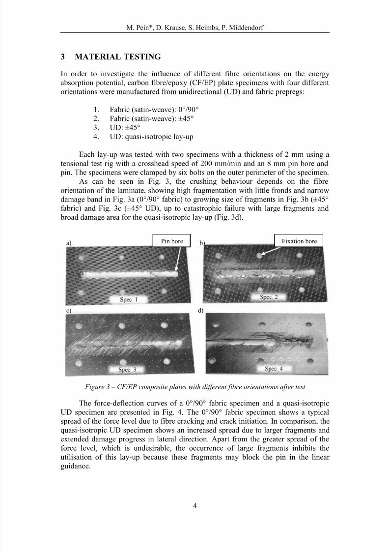
As can be seen in Fig. 3, the crushing behaviour depends on the fibre
orientation of the laminate, showing high fragmentation with little fronds and narrowdamage band in Fig. 3a (0°/90° fabric) to growing size of fragments in Fig. 3b (±45°
fabric) and Fig. 3c (±45° UD), up to catastrophic failure with large fragments and
broad damage area for the quasi-isotropic lay-up (Fig. 3d).
Figure 3 – CF/EP composite plates with different fibre orientations after test
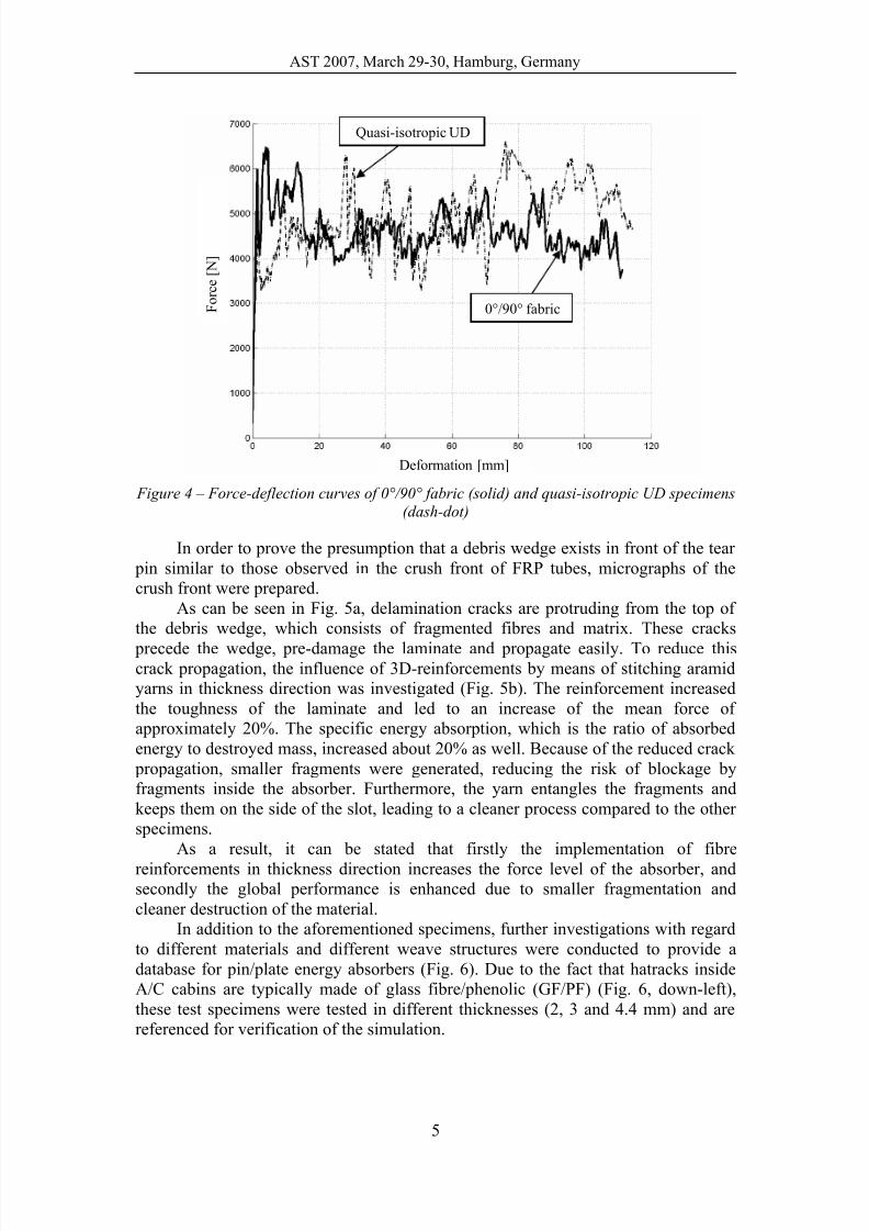
The force-deflection curves of a 0°/90° fabric specimen and a quasi-isotropic
UD specimen are presented in Fig. 4. The 0°/90° fabric specimen shows a typical
spread of the force level due to fibre cracking and crack initiation. In comparison, the
quasi-isotropic UD specimen shows an increased spread due to larger fragments and
extended damage progress in lateral direction. Apart from the greater spread of the
force level, which is undesirable, the occurrence of large fragments inhibits the
utilisation of this lay-up because these fragments may block the pin in the linear
guidance.
a) b)
c) d)
Pin bore Fixation bore
7/30/2019 Innovative Energy-Absorbing Concept for Aircraft Cabin Interior
http://slidepdf.com/reader/full/innovative-energy-absorbing-concept-for-aircraft-cabin-interior 5/10
AST 2007, March 29-30, Hamburg, Germany
5
0°/90° fabric
Quasi-isotropic UD
Figure 4 – Force-deflection curves of 0°/90° fabric (solid) and quasi-isotropic UD specimens
(dash-dot)
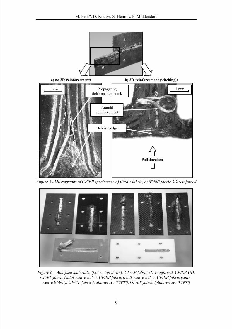
In order to prove the presumption that a debris wedge exists in front of the tear
pin similar to those observed in the crush front of FRP tubes, micrographs of the
crush front were prepared.
As can be seen in Fig. 5a, delamination cracks are protruding from the top of
the debris wedge, which consists of fragmented fibres and matrix. These cracks
precede the wedge, pre-damage the laminate and propagate easily. To reduce thiscrack propagation, the influence of 3D-reinforcements by means of stitching aramid
yarns in thickness direction was investigated (Fig. 5b). The reinforcement increased
the toughness of the laminate and led to an increase of the mean force of
approximately 20%. The specific energy absorption, which is the ratio of absorbed
energy to destroyed mass, increased about 20% as well. Because of the reduced crack
propagation, smaller fragments were generated, reducing the risk of blockage by
fragments inside the absorber. Furthermore, the yarn entangles the fragments and
keeps them on the side of the slot, leading to a cleaner process compared to the other
specimens.
As a result, it can be stated that firstly the implementation of fibre
reinforcements in thickness direction increases the force level of the absorber, andsecondly the global performance is enhanced due to smaller fragmentation and
cleaner destruction of the material.
In addition to the aforementioned specimens, further investigations with regard
to different materials and different weave structures were conducted to provide a
database for pin/plate energy absorbers (Fig. 6). Due to the fact that hatracks inside
A/C cabins are typically made of glass fibre/phenolic (GF/PF) (Fig. 6, down-left),
these test specimens were tested in different thicknesses (2, 3 and 4.4 mm) and are
referenced for verification of the simulation.
Deformation [mm]
F o r c e [ N ]
7/30/2019 Innovative Energy-Absorbing Concept for Aircraft Cabin Interior
http://slidepdf.com/reader/full/innovative-energy-absorbing-concept-for-aircraft-cabin-interior 6/10
M. Pein*, D. Krause, S. Heimbs, P. Middendorf
6
Figure 5 – Micrographs of CF/EP specimens: a) 0°/90° fabric, b) 0°/90° fabric 3D-reinforced
Figure 6 – Analysed materials, (f.l.t.r., top-down): CF/EP fabric 3D-reinforced, CF/EP UD,
CF/EP fabric (satin-weave ±45°), CF/EP fabric (twill-weave ±45°), CF/EP fabric (satin-
weave 0°/90°), GF/PF fabric (satin-weave 0°/90°), GF/EP fabric (plain-weave 0°/90°)
1 mm 1 mm
a) no 3D-reinforcement: b) 3D-reinforcement (stitching):
Pull direction
Debris wedge
Propagating
delamination crack
Aramid
reinforcement
7/30/2019 Innovative Energy-Absorbing Concept for Aircraft Cabin Interior
http://slidepdf.com/reader/full/innovative-energy-absorbing-concept-for-aircraft-cabin-interior 7/10
AST 2007, March 29-30, Hamburg, Germany
7
4 NUMERICAL SIMULATION
For design purposes of energy absorbers, a reliable prediction of the average crushing
load with respect to constituent materials, fibre orientation and plate thickness is
desirable. An established tool for such objectives is the dynamic finite element (FE)
method, but especially the in-plane crushing simulation of a thin plate is a complex
task. Ideally, several solid elements across the plate thickness should be used in order
to represent local crushing and delamination phenomena, which turned out to be
important energy absorption mechanisms. However, such a modelling approach leads
to small elements and therefore high computational cost, which makes such models
inefficient as a design tool. Consequently, modelling of the absorber plate with shell
elements is more practical. Shell theory does not account for stresses normal to the
shell plane, but since energy absorption happens in a very localised crash-front, these
may not be neglected. Interlaminar fracture or friction between single plies cannot be
represented either. Therefore numerical aids are typically used to solve this problem,
like the crash-front algorithm in the commercial FE-software LS-DYNA [10]. Sincedelaminations, occurring ahead of the crush-zone, cannot be represented physically in
the model, the crash-front parameter SOFT reduces the strength of the elements
neighbouring failed elements to capture this pre-damage effect. The parameter TFAIL
specifies at which deformation state elements are deleted.
Dynamic simulations of FRP energy absorbers with LS-DYNA incorporating
this crash-front algorithm can be found in [11]-[21]. Here, the energy absorption of
tubular specimens is investigated by means of shell element models, which also
represents an in-plane crushing of FRP material like in the case of the pin/plate-
absorber. All authors report a good correlation between their numerical and
experimental results. By contrast, similar investigations were carried out in [22],[23],
but these authors achieve no satisfying correlation, which they ascribe to thedisadvantages of the shell modelling approach. Dynamic simulations of similar
pin/plate-absorbers are reported in [24], but no experimental data for comparison
reasons are given.
To evaluate the merits and limits of numerical analysis of composite pin/plate-
absorbers with LS-DYNA, simulation models were developed using bilinear shell
elements of the Belytschko-Tsay-type with one-point-integration and layer-wise
definition of the FRP plies incorporating material model MAT54 for composites [10].
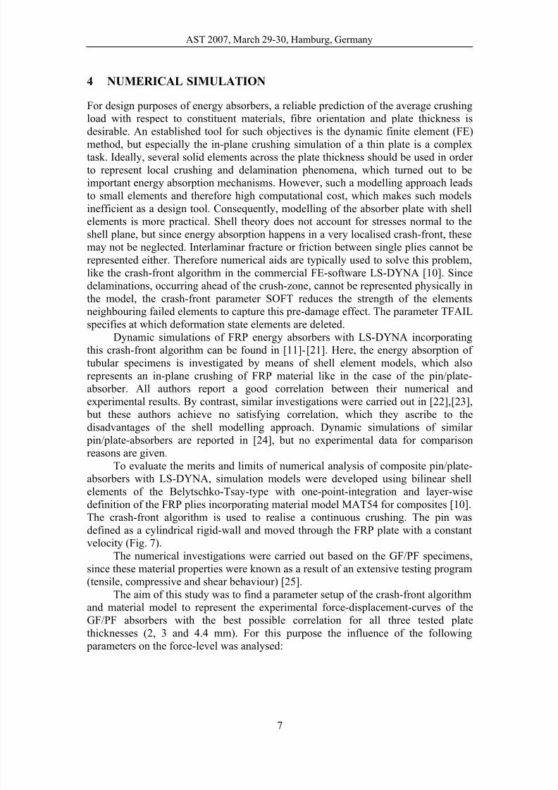
The crash-front algorithm is used to realise a continuous crushing. The pin was
defined as a cylindrical rigid-wall and moved through the FRP plate with a constant
velocity (Fig. 7).
The numerical investigations were carried out based on the GF/PF specimens,since these material properties were known as a result of an extensive testing program
(tensile, compressive and shear behaviour) [25].
The aim of this study was to find a parameter setup of the crash-front algorithm
and material model to represent the experimental force-displacement-curves of the
GF/PF absorbers with the best possible correlation for all three tested plate
thicknesses (2, 3 and 4.4 mm). For this purpose the influence of the following
parameters on the force-level was analysed:
7/30/2019 Innovative Energy-Absorbing Concept for Aircraft Cabin Interior
http://slidepdf.com/reader/full/innovative-energy-absorbing-concept-for-aircraft-cabin-interior 8/10
M. Pein*, D. Krause, S. Heimbs, P. Middendorf
8
Figure 7 – LS-DYNA simulation model of pin/plate-absorber
Influence of mesh refinement: The element size has a minor influence on the
average force level. Fine meshes tended to lead to more stable and less oscillating
results.
Influence of material model: The crash-front algorithm is implemented for different
composite material models in LS-DYNA. Comparisons in the according literature
show preferences of specific material models for different applications [19]-[22]. Inthis investigation material model MAT54 (based on the failure criteria by Chang-
Chang [10]) was compared to model MAT55 (based on the failure criteria by Tsai-
Wu [10]). The force level of MAT55 is significantly lower. In general, the correlation
to the experimental data was better for MAT54.
Influence of the material model/crash-front parameters: The crash-front
parameters SOFT and TFAIL as well as the compressive strength in the composite
material model are the major influence factors on the force level. An increase of
SOFT and the compressive strength raise the force level, while an increase of TFAIL
lowers the force level since each element has a lower allowable deformation and
absorbs less energy. Best results were obtained for SOFT=0.5 and TFAIL=0.3.
Influence of friction coefficient between pin and plate: The Coulomb friction
coefficient has a strong influence on the force level, since higher friction leads to
higher loads. Because high values led to lateral cracks in the plate, which were not
observed in the experiment, a value of µ=0.1 was used.
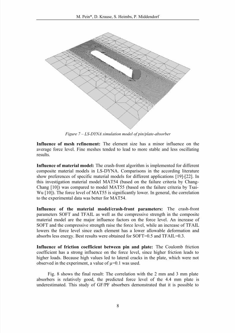
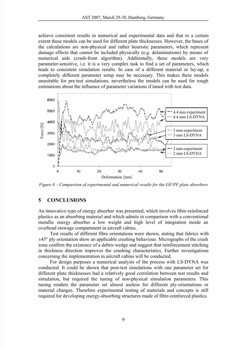
Fig. 8 shows the final result: The correlation with the 2 mm and 3 mm plate
absorbers is relatively good, the predicted force level of the 4.4 mm plate is
underestimated. This study of GF/PF absorbers demonstrated that it is possible to
7/30/2019 Innovative Energy-Absorbing Concept for Aircraft Cabin Interior
http://slidepdf.com/reader/full/innovative-energy-absorbing-concept-for-aircraft-cabin-interior 9/10
AST 2007, March 29-30, Hamburg, Germany
9
achieve consistent results in numerical and experimental data and that to a certain
extent these models can be used for different plate thicknesses. However, the bases of
the calculations are non-physical and rather heuristic parameters, which represent
damage effects that cannot be included physically (e.g. delaminations) by means of
numerical aids (crash-front algorithm). Additionally, these models are very
parameter-sensitive, i.e. it is a very complex task to find a set of parameters, which
leads to consistent simulation results. In case of a different material or lay-up, a
completely different parameter setup may be necessary. This makes these models
unsuitable for pre-test simulations; nevertheless the models can be used for rough
estimations about the influence of parameter variations if tuned with test data.
Figure 8 – Comparison of experimental and numerical results for the GF/PF plate absorbers
5 CONCLUSIONS
An innovative type of energy absorber was presented, which involves fibre-reinforced
plastics as an absorbing material and which admits in comparison with a conventional
metallic energy absorber a low weight and high level of integration inside an
overhead stowage compartment in aircraft cabins.
Test results of different fibre orientations were shown, stating that fabrics with
±45° ply orientation show an applicable crushing behaviour. Micrographs of the crush
zone confirm the existence of a debris wedge and suggest that reinforcement stitchingin thickness direction improves the crushing characteristics. Further investigations
concerning the implementation in aircraft cabins will be conducted.
For design purposes a numerical analysis of the process with LS-DYNA was
conducted. It could be shown that post-test simulations with one parameter set for
different plate thicknesses had a relatively good correlation between test results and
simulation, but required the tuning of non-physical simulation parameters. This
tuning renders the parameter set almost useless for different ply-orientations or
material changes. Therefore experimental testing of materials and concepts is still
required for developing energy-absorbing structures made of fibre-reinforced plastics.
2 mm experiment
2 mm LS-DYNA
3 mm experiment
3 mm LS-DYNA
4.4 mm experiment
4.4 mm LS-DYNA
Deformation [mm]
F o r c e [ N ]

7/30/2019 Innovative Energy-Absorbing Concept for Aircraft Cabin Interior
http://slidepdf.com/reader/full/innovative-energy-absorbing-concept-for-aircraft-cabin-interior 10/10
M. Pein*, D. Krause, S. Heimbs, P. Middendorf
10
6 REFERENCES
[1] M. Pein, V. Laukart, D. G. Feldmann, D. Krause: Concepts for energy absorbing support structures and appropriate materials. ICAS 2006, Hamburg, September 3-8, 2006.
[2] M. Pein, D. Krause: Leitfaden zur Entwicklung von Leichtbauenergieabsorbern in Flugzeug-
kabinen. 17. Symposium „Design for X“, Neukirchen, October 12-13, 2006 (in german).[3] W. Extra: Mechanische Absorptionsvorrichtung , Offenlegungsschrift DE 199 26 085, Deutsches
Patent- und Markenamt, 2000 (no patent assigned, in german).
[4] G. L. Farley, R. M. Jones: Crushing characteristics of continuous fiber-reinforced composite
tubes. Journal of composite Materials, Vol. 26, No. 1, pp 37-50, 1992.
[5] J. J. Carruthers, A. P. Kettle, A. M. Robinson: Energy absorption capability and crashworthinessof composite material structures: a review. Journal of Applied Mechanics , Vol. 56, No. 10, 1998.
[6] G. C. Jacob. et al.: Energy absorption in polymer composites for automotive crashworthiness. Journal of Composite Materials, Vol. 36, No. 7, pp 813-849, 2002.
[7] H.-W. Song, X.-W. Du, G.-F. Zhao: Energy absorption behavior of double-chamfer triggered glass/epoxy circular tubes, Journal of Composite Materials, Vol. 36, No. 18, 2002.
[8] M. Flemming, S. Roth, Faserverbund-Bauweisen, Springer Verlag, 2003 (in german).
[9] J. S. Marsolek: Energieabsorptionsverhalten zylinderschalenförmiger Strukturelemente aus Metall und Faserverbundwerkstoff, Ph.D. Thesis, Aachen, Shaker Verlag, 2002 (in german).
[10] LS-DYNA, Livermore Software Technology Corp., Livermore, USA, Keyword Manual, 2006.
[11] V. Agaram, et al.: Simulation of controlled failure of automotive composite structures with LS- DYNA3D. Proc. 12
thESD/SAE Advanced Composites Conf., Detroit, MI, April 7-10, 1997.
[12] M. Anghileri, L. M. L. Castelletti, F. Invernizzi, M. Mascheroni: Birdstrike onto the compositeintake of a turbofan engine. 5
thEurop. LS-DYNA Users Conf., Birmingham, May 25-26, 2005.
[13] H. El-Hage, P. K. Mallick, N. Zamani: Numerical modelling of quasi-static axial crush of squarealuminium-composite hybrid tubes. Int. J. of Crashworthiness, Vol. 9, No. 6, pp 653-664, 2004.
[14] A. Dehn: Experimentelle Untersuchung und numerische Simulation des Crashverhaltens gewebe-verstärkter Thermoplaste unter Temperatureinfluss, Ph.D. Thesis, Kaiserslautern, Germany, 2001.
[15] D. Imbsweiler: Experimentelle Untersuchung und numerische Simulation des Crashverhaltensvon SMC-Strukturen, Ph.D. Thesis, Kaiserslautern, Germany, 2001 (in german).
[16] M. Maier: Experimentelle Untersuchung und numerische Simulation des Crashverhaltens von Faserverbundwerkstoffen, Ph.D. Thesis, Kaiserslautern, Germany, 1990 (in german).
[17] A. Matzenmiller, K. Schweizerhof: Crashworthiness simulations of composite structures - a first
step with explicit time integration. Nonlinear Computational Mechanics: State of the Art,Springer, Berlin, pp 643-670, 1991.
[18] K. Schweizerhof, et al.: Energy absorption with composite crash elements in frontal crash - ananalysis with LS-DYNA3D. 11th CAD-FEM User s Meeting, Bamberg, 27.-29. Oct. 1993.
[19] K. Schweizerhof, T. Münz, K. Weimar, T. Rottner: Improving and testing the compositematerials in LS-DYNA for crash problems - a critical survey. CADFEM GmbH Grafing, 1998.
[20] M. Hörmann, M. Wacker: Simulation of the crash performance of crash boxes based on ad-vanced thermoplastic composit e. 5th Eur. LS-DYNA Users Conf., Birmingham, May 25-26, 2005.
[21] D. Papapostolou: Finite element modelling of the static axial compression and impact testing of square CFRP tubes in LS-DYNA3D. 5th Europ. LS-DYNA Users Conf., May 25-26, 2005.
[22] J. J. Carruthers: Some aspects of the energy absorption of composite materials, Ph.D. Thesis, TheUniversity of Sheffield, UK, 1997.
[23] M. R. S. Huisman: Experimental and numerical investigations for the prediction of the crash-worthyness of layered quasi-isotropic composites, Ph.D. Thesis, Kaiserslautern, Germany, 2001.
[24] C. Olschinka, A. Schumacher: Dynamic Simulation of Flight Passenger Seats. 5th
LS-DYNAAnwenderforum, Ulm, Germany, 2006.
[25] S. Heimbs, P. Middendorf, M. Maier: Honeycomb sandwich material modeling for dynamic simu-lations of aircraft interior components. 9th Int. LS-DYNA Users Conf., Dearborn, June 4-6, 2006.