
Injection Moulds for Beginners - Hanser · PDF fileInjection Moulds for Beginners Book ISBN:...
49
Sample Pages Rainer Dangel Injection Moulds for Beginners Book ISBN: 978-1-56990-631-6 eBook ISBN: 978-1-56990-632-3 For further information and order see http://www.hanser-fachbuch.de/978-1-56990-631-6 or contact your bookseller. © Carl Hanser Verlag, München
Transcript of Injection Moulds for Beginners - Hanser · PDF fileInjection Moulds for Beginners Book ISBN:...
Sample Pages
Rainer Dangel
Injection Moulds for Beginners
Book ISBN: 978-1-56990-631-6
eBook ISBN: 978-1-56990-632-3
For further information and order see
http://www.hanser-fachbuch.de/978-1-56990-631-6
or contact your bookseller.
© Carl Hanser Verlag, München

Dangel Injection Moulds for Beginners


Injection Moulds for Beginners
Rainer Dangel
Hanser Publishers, Munich Hanser Publications, Cincinnati

Distributed in the Americas by: Hanser Publications 6915 Valley Avenue, Cincinnati, Ohio 45244-3029, USA Fax: (513) 527-8801 Phone: (513) 527-8977 www.hanserpublications.com
Distributed in all other countries by: Carl Hanser Verlag Postfach 86 04 20, 81631 München, Germany Fax: +49 (89) 98 48 09 www.hanser-fachbuch.de
The use of general descriptive names, trademarks, etc., in this publication, even if the former are not especially identified, is not to be taken as a sign that such names, as understood by the Trade Marks and Merchandise Marks Act, may accordingly be used freely by anyone. While the advice and information in this book are believed to be true and accurate at the date of going to press, neither the authors nor the editors nor the publisher can accept any legal responsibility for any errors or omissions that may be made. The publisher makes no warranty, express or implied, with respect to the material contained herein.
The final determination of the suitability of any information for the use contemplated for a given application remains the sole responsibility of the user.
Cataloging-in-Publication Data is on file with the Library of Congress
All rights reserved. No part of this book may be reproduced or transmitted in any form or by any means, electronic or mechanical, including photocopying or by any information storage and retrieval system, without permission in writing from the publisher.
© Carl Hanser Verlag, Munich 2016 Editor: Mark Smith Translation: Kristin Bylund Thurnher, Meusburger Georg GmbH & Co KG First proofreader: Birgit Lins, Abteilungsleiterin Übersetzungsmanagement, Meusburger Georg GmbH & Co KG Production Management: Jörg Strohbach Coverconcept: Marc Müller-Bremer, www.rebranding.de, München Coverdesign: Stephan Rönigk Typesetting: Kösel Media GmbH, Krugzell Printed and bound by Hubert & Co GmbH, Göttingen Printed in Germany
ISBN: 978-1-56990-631-6 E-Book ISBN: 978-1-56990-632-3
The Author:
Rainer Dangel, 73266 Bissingen/Teck, Germany, [email protected]

German die and mould making is a brand with global significance. The reasons for this are diverse, but the industry’s secrets to success can certainly be attributed to smart design with a great deal of know-how, top performance production engineer-ing and quality related criteria. One major aim of this book is to disseminate this philosophy to a wider, English-speaking readership.
Rapid implementation of innovations through close information exchange between all parties is planned for the future. Injection moulds today already play a key role in modern production engineering in the manufacturing industry. Visions of the future such as the “smart factory” in the context of injection moulding now offer the chance to raise the energy and resource efficiency of the production process to a new level with intelligent management and network flexibility. But the basis for this is a solid knowledge of the basics of engineering and manufacturing processes in mould making. The above-mentioned topics can only be implemented based on this knowledge and wealth of experience. And this is exactly where this technical book from Rainer Dangel comes in. What is required for bringing a product into shape?
In the book the author didactically as well as technically breaks new ground in the field of technical literature for injection mould making. In a very clear way, he com-bines theory with practice, always focussing on the following questions: “What is this product relevant for? What needs to be solved technically for which product specifications?” And, regarding the method of the manufacturing implementation: “How and with what can I fulfil the product requirement within the scope of the design and also the manufacturing process?” Through Mr. Dangel’s technical expertise which he established and developed over many years, it quickly becomes clear when studying the book that the practical implementation of the described has great significance. Basic knowledge and solutions are holistically considered. Advantages and disadvantages are presented and discussed. The wealth of 35 years of experience, beginning with training as a tool maker to the master craftsman’s diploma then to owning a private company flows through this technical book.
Foreword

VI Foreword
“Injection Moulds for Beginners”, the title of this book, hits the bull’s eye and old hands who think it is no challenge to them might be taught a lesson!
Prof. Dr.-Ing. Thomas Seul
Vice rector for Research and Transfer at the Schmalkalden University of Applied Sciences and President of the Association of German Tool and Mold Makers (VDWF).

Foreword . . . . . . . . . . . . . . . . . . . . . . . . . . . . . . . . . . . . . . . . . . . . . . . . . . . . . . . V
The Author . . . . . . . . . . . . . . . . . . . . . . . . . . . . . . . . . . . . . . . . . . . . . . . . . . . . . . VII
Acknowledgement . . . . . . . . . . . . . . . . . . . . . . . . . . . . . . . . . . . . . . . . . . . . . . IX
How to Use This Book . . . . . . . . . . . . . . . . . . . . . . . . . . . . . . . . . . . . . . . . . . . XVII
1 Introduction . . . . . . . . . . . . . . . . . . . . . . . . . . . . . . . . . . . . . . . . . . . . . . . . 1
2 Mould Types . . . . . . . . . . . . . . . . . . . . . . . . . . . . . . . . . . . . . . . . . . . . . . . . 32.1 Simple Open/Close Mould . . . . . . . . . . . . . . . . . . . . . . . . . . . . . . . . . . . . . . 3
2.1.1 Classic Structure of an Open/Close Mould . . . . . . . . . . . . . . . . . . . 62.1.2 Guiding Elements . . . . . . . . . . . . . . . . . . . . . . . . . . . . . . . . . . . . . . . . 72.1.3 Backing Plate . . . . . . . . . . . . . . . . . . . . . . . . . . . . . . . . . . . . . . . . . . . 10
2.2 Moulds with Moving Elements . . . . . . . . . . . . . . . . . . . . . . . . . . . . . . . . . . 112.2.1 Undercut . . . . . . . . . . . . . . . . . . . . . . . . . . . . . . . . . . . . . . . . . . . . . . . 112.2.2 Slide . . . . . . . . . . . . . . . . . . . . . . . . . . . . . . . . . . . . . . . . . . . . . . . . . . . 122.2.3 Slide Operation . . . . . . . . . . . . . . . . . . . . . . . . . . . . . . . . . . . . . . . . . . 132.2.4 Latch, Clip Lock . . . . . . . . . . . . . . . . . . . . . . . . . . . . . . . . . . . . . . . . . 142.2.5 Inclined Ejector . . . . . . . . . . . . . . . . . . . . . . . . . . . . . . . . . . . . . . . . . 152.2.6 Forced Demoulding . . . . . . . . . . . . . . . . . . . . . . . . . . . . . . . . . . . . . . 172.2.7 Mould Size . . . . . . . . . . . . . . . . . . . . . . . . . . . . . . . . . . . . . . . . . . . . . 18
2.3 Mould for Threads . . . . . . . . . . . . . . . . . . . . . . . . . . . . . . . . . . . . . . . . . . . . . 192.3.1 External Threads . . . . . . . . . . . . . . . . . . . . . . . . . . . . . . . . . . . . . . . . 202.3.2 Internal Threads . . . . . . . . . . . . . . . . . . . . . . . . . . . . . . . . . . . . . . . . . 222.3.3 Drive Types for De-spindling . . . . . . . . . . . . . . . . . . . . . . . . . . . . . . 23
2.3.3.1 Hydraulic Unscrewing Unit . . . . . . . . . . . . . . . . . . . . . . . . . 232.3.3.2 Gear Rack . . . . . . . . . . . . . . . . . . . . . . . . . . . . . . . . . . . . . . . 242.3.3.3 High-Helix Lead Screw . . . . . . . . . . . . . . . . . . . . . . . . . . . . . 252.3.3.4 Multi-cavity Moulds . . . . . . . . . . . . . . . . . . . . . . . . . . . . . . . 27
Contents

XII Contents
2.4 Multi-component Injection Moulds . . . . . . . . . . . . . . . . . . . . . . . . . . . . . . . 282.4.1 Material Pairings . . . . . . . . . . . . . . . . . . . . . . . . . . . . . . . . . . . . . . . . 282.4.2 Mould Technology . . . . . . . . . . . . . . . . . . . . . . . . . . . . . . . . . . . . . . . 29
2.4.2.1 Shifting Technology . . . . . . . . . . . . . . . . . . . . . . . . . . . . . . . 292.4.2.2 Rotary Table Technology . . . . . . . . . . . . . . . . . . . . . . . . . . . 322.4.2.3 Sealing Slide Technology . . . . . . . . . . . . . . . . . . . . . . . . . . . 352.4.2.4 Further Technologies . . . . . . . . . . . . . . . . . . . . . . . . . . . . . . 35
2.5 Stack Mould . . . . . . . . . . . . . . . . . . . . . . . . . . . . . . . . . . . . . . . . . . . . . . . . . . 352.5.1 Material Combinations . . . . . . . . . . . . . . . . . . . . . . . . . . . . . . . . . . . 362.5.2 Hot Runner . . . . . . . . . . . . . . . . . . . . . . . . . . . . . . . . . . . . . . . . . . . . . 362.5.3 Opening and Closing . . . . . . . . . . . . . . . . . . . . . . . . . . . . . . . . . . . . . 372.5.4 Toggle Lever . . . . . . . . . . . . . . . . . . . . . . . . . . . . . . . . . . . . . . . . . . . . 402.5.5 Ejection . . . . . . . . . . . . . . . . . . . . . . . . . . . . . . . . . . . . . . . . . . . . . . . . 412.5.6 General Information on the Stack Mould . . . . . . . . . . . . . . . . . . . . 41
2.6 Further Literature . . . . . . . . . . . . . . . . . . . . . . . . . . . . . . . . . . . . . . . . . . . . . 42
3 Preparation . . . . . . . . . . . . . . . . . . . . . . . . . . . . . . . . . . . . . . . . . . . . . . . . . 433.1 CAD System . . . . . . . . . . . . . . . . . . . . . . . . . . . . . . . . . . . . . . . . . . . . . . . . . . 43
3.2 Data Transfer, Procedure, and Processing . . . . . . . . . . . . . . . . . . . . . . . . . 443.2.1 Data Transfer . . . . . . . . . . . . . . . . . . . . . . . . . . . . . . . . . . . . . . . . . . . 453.2.2 Formats . . . . . . . . . . . . . . . . . . . . . . . . . . . . . . . . . . . . . . . . . . . . . . . . 45
3.2.2.1 IGES . . . . . . . . . . . . . . . . . . . . . . . . . . . . . . . . . . . . . . . . . . . . 453.2.2.2 STEP . . . . . . . . . . . . . . . . . . . . . . . . . . . . . . . . . . . . . . . . . . . . 463.2.2.3 STL . . . . . . . . . . . . . . . . . . . . . . . . . . . . . . . . . . . . . . . . . . . . . 46
3.2.3 Data Size . . . . . . . . . . . . . . . . . . . . . . . . . . . . . . . . . . . . . . . . . . . . . . . 483.2.4 Shrinkage . . . . . . . . . . . . . . . . . . . . . . . . . . . . . . . . . . . . . . . . . . . . . . 48
3.2.4.1 Material Selection . . . . . . . . . . . . . . . . . . . . . . . . . . . . . . . . . 483.2.4.2 Shrinkage (Physical Process) . . . . . . . . . . . . . . . . . . . . . . . 493.2.4.3 Influencing Variables . . . . . . . . . . . . . . . . . . . . . . . . . . . . . . 49
3.2.5 Calculation and Impact . . . . . . . . . . . . . . . . . . . . . . . . . . . . . . . . . . . 513.2.5.1 Free Shrinkage, Constrained Shrinkage . . . . . . . . . . . . . . 533.2.5.2 Warping . . . . . . . . . . . . . . . . . . . . . . . . . . . . . . . . . . . . . . . . . 56
3.3 Specifications . . . . . . . . . . . . . . . . . . . . . . . . . . . . . . . . . . . . . . . . . . . . . . . . . 593.3.1 Location of the Component inside the Injection Mould . . . . . . . . . 59
3.3.1.1 Demoulding Direction . . . . . . . . . . . . . . . . . . . . . . . . . . . . . 593.3.2 Number of Cavities . . . . . . . . . . . . . . . . . . . . . . . . . . . . . . . . . . . . . . . 633.3.3 Arrangement of Cavities . . . . . . . . . . . . . . . . . . . . . . . . . . . . . . . . . . 66
3.4 Material Selection for Injection Moulds . . . . . . . . . . . . . . . . . . . . . . . . . . . 71
3.5 Mould Size . . . . . . . . . . . . . . . . . . . . . . . . . . . . . . . . . . . . . . . . . . . . . . . . . . . 74
XIIIContents
3.6 Plate Thickness . . . . . . . . . . . . . . . . . . . . . . . . . . . . . . . . . . . . . . . . . . . . . . . 77
3.7 Demoulding . . . . . . . . . . . . . . . . . . . . . . . . . . . . . . . . . . . . . . . . . . . . . . . . . . 783.7.1 Basic Principle of Demoulding . . . . . . . . . . . . . . . . . . . . . . . . . . . . . 783.7.2 Draft Angles . . . . . . . . . . . . . . . . . . . . . . . . . . . . . . . . . . . . . . . . . . . . 78
3.7.2.1 Definition . . . . . . . . . . . . . . . . . . . . . . . . . . . . . . . . . . . . . . . . 793.7.2.2 Effect on the Opening of the Mould . . . . . . . . . . . . . . . . . . 803.7.2.3 Draft Angle in the Split Line Face . . . . . . . . . . . . . . . . . . . . 813.7.2.4 Demoulding Problems and Solutions . . . . . . . . . . . . . . . . . 83
3.8 Split Line Face . . . . . . . . . . . . . . . . . . . . . . . . . . . . . . . . . . . . . . . . . . . . . . . . 873.8.1 Plain Split Line Face . . . . . . . . . . . . . . . . . . . . . . . . . . . . . . . . . . . . . 873.8.2 Contour-Forming Split Line Face . . . . . . . . . . . . . . . . . . . . . . . . . . . 883.8.3 Jumping Split Line Face . . . . . . . . . . . . . . . . . . . . . . . . . . . . . . . . . . . 883.8.4 Wear Plates in the Split . . . . . . . . . . . . . . . . . . . . . . . . . . . . . . . . . . . 903.8.5 Visible Split Line . . . . . . . . . . . . . . . . . . . . . . . . . . . . . . . . . . . . . . . . 91
3.9 Injection . . . . . . . . . . . . . . . . . . . . . . . . . . . . . . . . . . . . . . . . . . . . . . . . . . . . . 933.9.1 Injection and Feed Point . . . . . . . . . . . . . . . . . . . . . . . . . . . . . . . . . . 933.9.2 Simulation . . . . . . . . . . . . . . . . . . . . . . . . . . . . . . . . . . . . . . . . . . . . . . 953.9.3 Sprue System, Sprue Type . . . . . . . . . . . . . . . . . . . . . . . . . . . . . . . . 101
3.9.3.1 Cold Runner . . . . . . . . . . . . . . . . . . . . . . . . . . . . . . . . . . . . . 1013.9.3.2 Hot Runner . . . . . . . . . . . . . . . . . . . . . . . . . . . . . . . . . . . . . . 102
3.9.4 Runner . . . . . . . . . . . . . . . . . . . . . . . . . . . . . . . . . . . . . . . . . . . . . . . . . 1033.9.5 Sprue on the Part . . . . . . . . . . . . . . . . . . . . . . . . . . . . . . . . . . . . . . . . 1053.9.6 Tunnel Gate . . . . . . . . . . . . . . . . . . . . . . . . . . . . . . . . . . . . . . . . . . . . . 1063.9.7 Film Gate . . . . . . . . . . . . . . . . . . . . . . . . . . . . . . . . . . . . . . . . . . . . . . . 1113.9.8 Diaphragm Gate . . . . . . . . . . . . . . . . . . . . . . . . . . . . . . . . . . . . . . . . . 1123.9.9 Hot Runner Single Nozzle . . . . . . . . . . . . . . . . . . . . . . . . . . . . . . . . . 1143.9.10 Hot Runner Distributor . . . . . . . . . . . . . . . . . . . . . . . . . . . . . . . . . . . 1163.9.11 Hot Runner Distribution System with Needle Valve . . . . . . . . . . . . 118
3.9.11.1 Integral Hinge . . . . . . . . . . . . . . . . . . . . . . . . . . . . . . . . . . . . 1223.9.12 Three-Plate Mould . . . . . . . . . . . . . . . . . . . . . . . . . . . . . . . . . . . . . . . 1233.9.13 Tunnel Gate Inserts . . . . . . . . . . . . . . . . . . . . . . . . . . . . . . . . . . . . . . 126
3.10 Ventilation . . . . . . . . . . . . . . . . . . . . . . . . . . . . . . . . . . . . . . . . . . . . . . . . . . . 1273.10.1 General Information about Ventilation . . . . . . . . . . . . . . . . . . . . . . 1273.10.2 Ventilation via Components . . . . . . . . . . . . . . . . . . . . . . . . . . . . . . . 1303.10.3 Geometric Design of Ventilation . . . . . . . . . . . . . . . . . . . . . . . . . . . . 132
3.11 Further Literature . . . . . . . . . . . . . . . . . . . . . . . . . . . . . . . . . . . . . . . . . . . . . 134
XIV Contents
4 Components . . . . . . . . . . . . . . . . . . . . . . . . . . . . . . . . . . . . . . . . . . . . . . . . 1354.1 Mould Inserts/Mould Cores . . . . . . . . . . . . . . . . . . . . . . . . . . . . . . . . . . . . . 135
4.1.1 Mould Inserts . . . . . . . . . . . . . . . . . . . . . . . . . . . . . . . . . . . . . . . . . . . 1354.1.2 Mould Cores . . . . . . . . . . . . . . . . . . . . . . . . . . . . . . . . . . . . . . . . . . . . 140
4.2 Slides . . . . . . . . . . . . . . . . . . . . . . . . . . . . . . . . . . . . . . . . . . . . . . . . . . . . . . . 1444.2.1 Application Areas of Slides . . . . . . . . . . . . . . . . . . . . . . . . . . . . . . . . 1444.2.2 Design of a Slide . . . . . . . . . . . . . . . . . . . . . . . . . . . . . . . . . . . . . . . . . 146
4.2.2.1 Mould Contour . . . . . . . . . . . . . . . . . . . . . . . . . . . . . . . . . . . 1474.2.2.2 Split Line on Slide . . . . . . . . . . . . . . . . . . . . . . . . . . . . . . . . . 1484.2.2.3 Slide Body and Guiding . . . . . . . . . . . . . . . . . . . . . . . . . . . . 1504.2.2.4 Operation of Slides . . . . . . . . . . . . . . . . . . . . . . . . . . . . . . . . 1524.2.2.5 Locking in the End Position . . . . . . . . . . . . . . . . . . . . . . . . . 1574.2.2.6 Cooling in Slide . . . . . . . . . . . . . . . . . . . . . . . . . . . . . . . . . . . 161
4.2.3 Further Slide Concepts . . . . . . . . . . . . . . . . . . . . . . . . . . . . . . . . . . . 1624.2.3.1 Slide in Slide . . . . . . . . . . . . . . . . . . . . . . . . . . . . . . . . . . . . . 1634.2.3.2 “Backpack” Slide . . . . . . . . . . . . . . . . . . . . . . . . . . . . . . . . . . 165
4.3 Ejectors . . . . . . . . . . . . . . . . . . . . . . . . . . . . . . . . . . . . . . . . . . . . . . . . . . . . . . 1674.3.1 Types of Ejectors . . . . . . . . . . . . . . . . . . . . . . . . . . . . . . . . . . . . . . . . 1694.3.2 Ejectors as Auxiliary Tools . . . . . . . . . . . . . . . . . . . . . . . . . . . . . . . . 1744.3.3 Inclined Ejectors . . . . . . . . . . . . . . . . . . . . . . . . . . . . . . . . . . . . . . . . . 1764.3.4 Stripper Plate . . . . . . . . . . . . . . . . . . . . . . . . . . . . . . . . . . . . . . . . . . . 1784.3.5 Two-Stage Ejectors . . . . . . . . . . . . . . . . . . . . . . . . . . . . . . . . . . . . . . . 1804.3.6 Collapsible Cores . . . . . . . . . . . . . . . . . . . . . . . . . . . . . . . . . . . . . . . . 1824.3.7 Forced Demoulding . . . . . . . . . . . . . . . . . . . . . . . . . . . . . . . . . . . . . . 183
4.4 Cooling System . . . . . . . . . . . . . . . . . . . . . . . . . . . . . . . . . . . . . . . . . . . . . . . 1834.4.1 Cooling Type and Auxiliary Equipment . . . . . . . . . . . . . . . . . . . . . 186
4.4.1.1 Drilled Cooling . . . . . . . . . . . . . . . . . . . . . . . . . . . . . . . . . . . 1884.4.1.2 Redirection of Cooling Circuits . . . . . . . . . . . . . . . . . . . . . . 1904.4.1.3 Copper Cores . . . . . . . . . . . . . . . . . . . . . . . . . . . . . . . . . . . . . 1954.4.1.4 Heating Cartridges . . . . . . . . . . . . . . . . . . . . . . . . . . . . . . . . 1964.4.1.5 Connection of circuits . . . . . . . . . . . . . . . . . . . . . . . . . . . . . 197
4.4.2 Connection and Sealing of Cooling Holes . . . . . . . . . . . . . . . . . . . . 198
4.5 Components and Marking . . . . . . . . . . . . . . . . . . . . . . . . . . . . . . . . . . . . . . 200
4.6 Surface . . . . . . . . . . . . . . . . . . . . . . . . . . . . . . . . . . . . . . . . . . . . . . . . . . . . . . 2024.6.1 Rough Surface . . . . . . . . . . . . . . . . . . . . . . . . . . . . . . . . . . . . . . . . . . . 2034.6.2 EDM . . . . . . . . . . . . . . . . . . . . . . . . . . . . . . . . . . . . . . . . . . . . . . . . . . . 2044.6.3 Graining . . . . . . . . . . . . . . . . . . . . . . . . . . . . . . . . . . . . . . . . . . . . . . . 2064.6.4 Laser Texturing . . . . . . . . . . . . . . . . . . . . . . . . . . . . . . . . . . . . . . . . . 2074.6.5 Polishing . . . . . . . . . . . . . . . . . . . . . . . . . . . . . . . . . . . . . . . . . . . . . . . 208
XVContents
4.7 Systematic Design Approach . . . . . . . . . . . . . . . . . . . . . . . . . . . . . . . . . . . . 2094.7.1 Strategy . . . . . . . . . . . . . . . . . . . . . . . . . . . . . . . . . . . . . . . . . . . . . . . . 2094.7.2 Standard Parts . . . . . . . . . . . . . . . . . . . . . . . . . . . . . . . . . . . . . . . . . . 2114.7.3 Manufactured Parts . . . . . . . . . . . . . . . . . . . . . . . . . . . . . . . . . . . . . . 213
4.8 Further Literature . . . . . . . . . . . . . . . . . . . . . . . . . . . . . . . . . . . . . . . . . . . . . 215
5 Assembly . . . . . . . . . . . . . . . . . . . . . . . . . . . . . . . . . . . . . . . . . . . . . . . . . . . 2175.1 Systematic Assembly . . . . . . . . . . . . . . . . . . . . . . . . . . . . . . . . . . . . . . . . . . 217
5.2 Spotting . . . . . . . . . . . . . . . . . . . . . . . . . . . . . . . . . . . . . . . . . . . . . . . . . . . . . 222
5.3 Connection of Components . . . . . . . . . . . . . . . . . . . . . . . . . . . . . . . . . . . . . . 224
5.4 Check the Cooling for Leaks . . . . . . . . . . . . . . . . . . . . . . . . . . . . . . . . . . . . . 227
5.5 Further Literature . . . . . . . . . . . . . . . . . . . . . . . . . . . . . . . . . . . . . . . . . . . . . 229
6 Further Knowledge . . . . . . . . . . . . . . . . . . . . . . . . . . . . . . . . . . . . . . . . . . 2316.1 Process Chain in Mould Making . . . . . . . . . . . . . . . . . . . . . . . . . . . . . . . . . 231
6.2 Quality Assurance . . . . . . . . . . . . . . . . . . . . . . . . . . . . . . . . . . . . . . . . . . . . . 233
6.3 Fits and Play in the Mould: What Must Fit? . . . . . . . . . . . . . . . . . . . . . . . . 235
6.4 Heat Treatment . . . . . . . . . . . . . . . . . . . . . . . . . . . . . . . . . . . . . . . . . . . . . . . 2396.4.1 Annealing . . . . . . . . . . . . . . . . . . . . . . . . . . . . . . . . . . . . . . . . . . . . . . 2406.4.2 Hardening . . . . . . . . . . . . . . . . . . . . . . . . . . . . . . . . . . . . . . . . . . . . . . 2416.4.3 Nitriding . . . . . . . . . . . . . . . . . . . . . . . . . . . . . . . . . . . . . . . . . . . . . . . 243
6.5 Coatings . . . . . . . . . . . . . . . . . . . . . . . . . . . . . . . . . . . . . . . . . . . . . . . . . . . . . 245
6.6 Changes: What Is to Be Considered? . . . . . . . . . . . . . . . . . . . . . . . . . . . . . . 246
6.7 Further Literature . . . . . . . . . . . . . . . . . . . . . . . . . . . . . . . . . . . . . . . . . . . . . 248
7 The Finished Mould . . . . . . . . . . . . . . . . . . . . . . . . . . . . . . . . . . . . . . . . . 2497.1 Mould Validation . . . . . . . . . . . . . . . . . . . . . . . . . . . . . . . . . . . . . . . . . . . . . . 249
7.1.1 Clamping and Connecting the Media . . . . . . . . . . . . . . . . . . . . . . . . 2497.1.2 Filling of the Mould . . . . . . . . . . . . . . . . . . . . . . . . . . . . . . . . . . . . . . 252
7.1.2.1 Balancing Cavities . . . . . . . . . . . . . . . . . . . . . . . . . . . . . . . . 2547.1.2.2 Optimising the Parameters . . . . . . . . . . . . . . . . . . . . . . . . . 2567.1.2.3 Influence on the Injection Process . . . . . . . . . . . . . . . . . . . 257
7.1.3 Parameters during Injection . . . . . . . . . . . . . . . . . . . . . . . . . . . . . . . 2577.1.4 Forces Acting in the Mould during the Injection Process . . . . . . . 2587.1.5 Initial Sample Inspection Report . . . . . . . . . . . . . . . . . . . . . . . . . . . 260
7.2 Labels on the Mould . . . . . . . . . . . . . . . . . . . . . . . . . . . . . . . . . . . . . . . . . . . 261
7.3 Further Literature . . . . . . . . . . . . . . . . . . . . . . . . . . . . . . . . . . . . . . . . . . . . . 262
XVI Contents
8 Maintenance and Repair . . . . . . . . . . . . . . . . . . . . . . . . . . . . . . . . . . . . . 2638.1 Maintenance Schedule . . . . . . . . . . . . . . . . . . . . . . . . . . . . . . . . . . . . . . . . . 263
8.2 Welding . . . . . . . . . . . . . . . . . . . . . . . . . . . . . . . . . . . . . . . . . . . . . . . . . . . . . . 2648.2.1 Tungsten Inert Gas Welding (TIG) . . . . . . . . . . . . . . . . . . . . . . . . . . 2648.2.2 Laser Beam Welding . . . . . . . . . . . . . . . . . . . . . . . . . . . . . . . . . . . . . 265
8.3 Component Replacement . . . . . . . . . . . . . . . . . . . . . . . . . . . . . . . . . . . . . . . 266
8.4 Further Literature . . . . . . . . . . . . . . . . . . . . . . . . . . . . . . . . . . . . . . . . . . . . . 267
9 Manufacturing Technologies . . . . . . . . . . . . . . . . . . . . . . . . . . . . . . . . . 2699.1 Milling . . . . . . . . . . . . . . . . . . . . . . . . . . . . . . . . . . . . . . . . . . . . . . . . . . . . . . 269
9.1.1 3-Axis Milling . . . . . . . . . . . . . . . . . . . . . . . . . . . . . . . . . . . . . . . . . . . 2719.1.2 4- and 5-Axis Milling . . . . . . . . . . . . . . . . . . . . . . . . . . . . . . . . . . . . . 273
9.1.2.1 4-Axis Milling . . . . . . . . . . . . . . . . . . . . . . . . . . . . . . . . . . . . 2739.1.2.2 5-Axis Milling . . . . . . . . . . . . . . . . . . . . . . . . . . . . . . . . . . . . 2749.1.2.3 3+2-Axis Milling . . . . . . . . . . . . . . . . . . . . . . . . . . . . . . . . . . 2759.1.2.4 Simultaneous 5-Axis Milling . . . . . . . . . . . . . . . . . . . . . . . . 276
9.1.3 CAM Programming . . . . . . . . . . . . . . . . . . . . . . . . . . . . . . . . . . . . . . 278
9.2 EDM . . . . . . . . . . . . . . . . . . . . . . . . . . . . . . . . . . . . . . . . . . . . . . . . . . . . . . . . 2829.2.1 Sinker EDM . . . . . . . . . . . . . . . . . . . . . . . . . . . . . . . . . . . . . . . . . . . . . 2839.2.2 Wire EDM . . . . . . . . . . . . . . . . . . . . . . . . . . . . . . . . . . . . . . . . . . . . . . 285
9.3 Grinding/Profile Grinding . . . . . . . . . . . . . . . . . . . . . . . . . . . . . . . . . . . . . . 286
9.4 Drilling/Deep Hole Drilling . . . . . . . . . . . . . . . . . . . . . . . . . . . . . . . . . . . . . 287
9.5 Turning . . . . . . . . . . . . . . . . . . . . . . . . . . . . . . . . . . . . . . . . . . . . . . . . . . . . . . 289
9.6 New Technologies . . . . . . . . . . . . . . . . . . . . . . . . . . . . . . . . . . . . . . . . . . . . . 2909.6.1 LaserCUSING®/Laser Sintering . . . . . . . . . . . . . . . . . . . . . . . . . . . . 2909.6.2 Vacuum Soldering . . . . . . . . . . . . . . . . . . . . . . . . . . . . . . . . . . . . . . . 291
9.7 Polishing . . . . . . . . . . . . . . . . . . . . . . . . . . . . . . . . . . . . . . . . . . . . . . . . . . . . . 293
9.8 Further Literature . . . . . . . . . . . . . . . . . . . . . . . . . . . . . . . . . . . . . . . . . . . . . 293
10 Practical Guidelines . . . . . . . . . . . . . . . . . . . . . . . . . . . . . . . . . . . . . . . . . 29510.1 Design Check List . . . . . . . . . . . . . . . . . . . . . . . . . . . . . . . . . . . . . . . . . . . . . 297
10.2 Design Colour Chart . . . . . . . . . . . . . . . . . . . . . . . . . . . . . . . . . . . . . . . . . . . 298
10.3 Sequential Function Chart . . . . . . . . . . . . . . . . . . . . . . . . . . . . . . . . . . . . . . 299
10.4 Maintenance Schedule . . . . . . . . . . . . . . . . . . . . . . . . . . . . . . . . . . . . . . . . . 300
10.5 Formulas and Calculations . . . . . . . . . . . . . . . . . . . . . . . . . . . . . . . . . . . . . . 301
Index . . . . . . . . . . . . . . . . . . . . . . . . . . . . . . . . . . . . . . . . . . . . . . . . . . . . . . . . . . . 303
2�� 2.1�Simple Open/Close Mould
The open/close mould got its name from its easy movement and function when the injection mould for machining of the plastic parts is clamped onto an injection moulding machine. The injection mould or the injection moulding machine opens and closes without any further necessary movement taking place in the injection mould.
The entire motion sequence is called an injection cycle or just cycle. It begins with a closing of the injection mould. When it is closed, a liquid, hot plastic mass is injected into the injection mould under pressure. Now a certain amount of time must pass before the liquid plastic has cooled and solidified and the plastic part in the injection mould reaches a certain stability. The injection mould opens and the finished, still-warm plastic parts are ejected from the injection mould. When all of the movements are finished, the process starts again. For the outside observer, the machine opens and closes again and again.
The direction in which the injection mould or the injection moulding machine opens and closes is called the main demoulding direction. All movements of the injection moulding machine, the injection moulds and the moving parts in the injection mould run in this axial direction. Depending on the component there can be additional demoulding directions. This is described in Section 2.2.
The open/close mould is the simplest of all injection moulds. As a result it is often the cheapest. Already in the planning and designing of plastic parts, efforts are made so that the plastic piece can be produced with this type of injection mould.
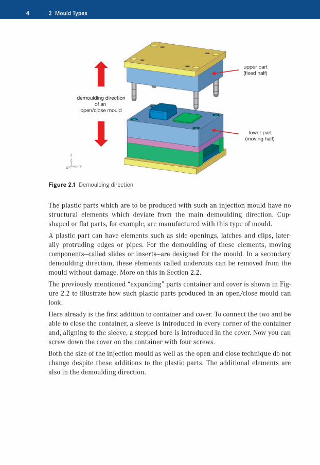
Figure 2.1 shows the demoulding direction of a simple open/close mould. Both upper part (fixed half) and lower part (moving half) open and close in an axial direction. The plastic part has been designed for being produced with this specific mould in such a way that when opening the mould on the injection moulding machine it is not damaged or destroyed.
Mould Types
4 2 Mould Types
demoulding directionof an
open/close mould
upper part(fixed half)
lower part(moving half)
Figure 2.1 Demoulding direction
The plastic parts which are to be produced with such an injection mould have no structural elements which deviate from the main demoulding direction. Cup-shaped or flat parts, for example, are manufactured with this type of mould.
A plastic part can have elements such as side openings, latches and clips, later-ally protruding edges or pipes. For the demoulding of these elements, moving components—called slides or inserts—are designed for the mould. In a secondary demoulding direction, these elements called undercuts can be removed from the mould without damage. More on this in Section 2.2.
The previously mentioned “expanding” parts container and cover is shown in Fig-ure 2.2 to illustrate how such plastic parts produced in an open/close mould can look.
Here already is the first addition to container and cover. To connect the two and be able to close the container, a sleeve is introduced in every corner of the container and, aligning to the sleeve, a stepped bore is introduced in the cover. Now you can screw down the cover on the container with four screws.
Both the size of the injection mould as well as the open and close technique do not change despite these additions to the plastic parts. The additional elements are also in the demoulding direction.
12 2 Mould Types
side opening example
second demoulding
direction
seconddemoulding
directionside pipe example
main demoulding direction
Figure 2.10 Additional demoulding directions
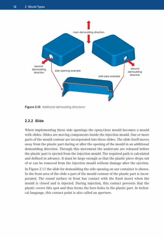
2.2.2�Slide
When implementing these side openings the open/close mould becomes a mould with slides. Slides are moving components inside the injection mould. One or more parts of the mould contour are incorporated into these slides. The slide itself moves away from the plastic part during or after the opening of the mould in an additional demoulding direction. Through this movement the undercuts are released before the plastic part is ejected from the injection mould. The required path is calculated and defined in advance. It must be large enough so that the plastic piece drops out of or can be removed from the injection mould without damage after the ejection.
In Figure 2.11 the slide for demoulding the side opening on our container is shown. In the front area of the slide a part of the mould contour of the plastic part is incor-porated. The round surface in front has contact with the fixed insert when the mould is closed and is injected. During injection, this contact prevents that the plastic covers this spot and thus forms the bore holes in the plastic part. In techni-cal language, this contact point is also called an aperture.

132.2 Moulds with Moving Elements
Slide with Plastic Part
slide mould contour
Slide without Plastic Part
contact to the insertfor the aperture
Figure 2.11 Slide with and without plastic part
2.2.3�Slide Operation
To move this slide there are two possibilities. The first possibility is that the slide is connected with a hydraulic cylinder which is in turn screwed tightly to the injec-tion mould. The slide is moved via this cylinder. For this solution the cylinder covers a clearly defined distance. It is bought and installed as a standard part. Find out more in Section 4.2. The second option is the forced control through an inclined pin. The pin is installed with a defined inclination on the fixed half of the injection mould. The front part of the inclined pin submerges in the moving slide. When the mould opens in the main demoulding direction, through the resulting movement this inclined pin moves the slide in an additional demoulding direction. There are additional details in Section 4.2.
Figure 2.12 displays the closed mould on the left and the slightly open mould on the right. On the slightly open mould the inclined pin has moved the slide in an additional demoulding direction to the end position.
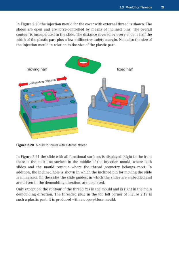
212.3 Mould for Threads
In Figure 2.20 the injection mould for the cover with external thread is shown. The slides are open and are force-controlled by means of inclined pins. The overall contour is incorporated in the slide. The distance covered by every slide is half the width of the plastic part plus a few millimetres safety margin. Note also the size of the injection mould in relation to the size of the plastic part.
fixed halfmoving half
demoulding direction
Figure 2.20 Mould for cover with external thread
In Figure 2.21 the slide with all functional surfaces is displayed. Right in the front there is the split line surface in the middle of the injection mould, where both slides and the mould contour—where the thread geometry belongs—meet. In addition, the inclined hole is shown in which the inclined pin for moving the slide is immersed. On the sides the slide guides, in which the slides are embedded and are driven in the demoulding direction, are displayed.
Only exception: the contour of the thread lies in the mould and is right in the main demoulding direction. The threaded plug in the top left corner of Figure 2.19 is such a plastic part. It is produced with an open/close mould.
232.3 Mould for Threads
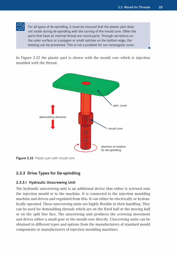
For all types of de-spindling, it must be ensured that the plastic part does not rotate during de-spindling with the turning of the mould core. Often the parts that have an internal thread are round parts. Through serrations on the outer surface or a polygon or small catches on the bottom edge, the twisting can be prevented. This is not a problem for our rectangular cover.
In Figure 2.22 the plastic part is shown with the mould core which is injection moulded with the thread.
demoulding direction
part, cover
mould core
direction of rotation for de-spindling
Figure 2.22 Plastic part with mould core
2.3.3�Drive Types for De-spindling
2.3.3.1�Hydraulic Unscrewing UnitThe hydraulic unscrewing unit is an additional device that either is screwed onto the injection mould or to the machine. It is connected to the injection moulding machine and driven and regulated from this. It can either be electrically or hydrau-lically operated. These unscrewing units are highly flexible in their handling. They can be used for demoulding threads which are on the fixed half or the moving half or on the split line face. The unscrewing unit produces the screwing movement and drives either a small gear or the mould core directly. Unscrewing units can be obtained in different types and options from the manufacturers of standard mould components or manufacturers of injection moulding machines.

372.5 Stack Mould
injection moulding machine (moving half 2 in Figure 2.35). This hot runner is only the feeder for the plastic. In the middle section the hot runner with the distributor which fills the entire cavity with plastic is located. In the split line between fixed half 2 and the moving half 2 (see Figure 2.35) there is a transfer point for the plas-tic. Through the opening and closing of the mould this transfer point between the two hot runners is separated and connected again once in every cycle.
In Figure 2.36, a hot runner system has been integrated in the mould. The transfer point can be seen in the split line 2 (see Figure 2.35). The plastic is injected cen-trally through the machine nozzle.
hot runner transfer point
mac
hine
: fixe
d h
alf
mac
hine
: mov
ing
half
hot
runn
er 1
central injection through the machine nozzle
hot
runn
er d
istr
ibut
or
Figure 2.36 Stack mould with hot runner
2.5.3�Opening and Closing
The mould is clamped as usual to the injection moulding machine: with a clamping plate on the left to the moving half machine plate and with a clamping plate on the right on the fixed half machine plate. The central part of the mould is held in the centre by the guiding between the two moving halves. For this special case, in some machines there are sliding guides on the machine base and the central part is supported with a guide shoe.

38 2 Mould Types
In Figure 2.37 the injection mould is clamped on the machine. The central part is supported on both sides by the guide shoe.
guide shoe
moving half 1 moving half 2central part
mac
hine
: mov
ing
half
mac
hine
: fixe
d h
alf
machine base
guiding
gear for controlled opening of the mould
Figure 2.37 Injection mould installed on the machine
When opening and closing, the machine or the injection mould covers a certain distance, in our example 400 mm. The central part is controlled through the gear and travels half the distance, that is, 200 mm, and the opening width is the same for both split lines.
Figure 2.38 illustrates the situation for an open mould. The machine has travelled 400 mm and the opening width of each split line is 200 mm. Therefore there is enough space for the finished plastic pieces to fall from the mould.
For an even better visualisation of this concept, a three-dimensional view of the open injection mould with gear and external guiding is displayed in Figure 2.39.

653.3 Specifications
Examples of an Economic Efficiency Calculation:
Requirements for a plastic part over the entire service life of 100,000 pieces.
� Cost for the 1-cavity mould: $20,000. The price per part produced with the 1-cav-ity mould is $0.50/piece. 100,000 pieces x $0.50 results in an overall cost for the parts of $50,000. Together with the mould costs, a total of $70,000 is calculated over the entire service life.
� In contrast, the 2-cavity mould costs $30,000 but because two parts instead of one part comes out of each machine in every cycle the price per part is only $0.30/piece. If you sum up the costs for the 2-cavity mould, the overall cost for the parts is $30,000 and the overall cost for the mould is $30,000, which together makes $60,000.Result: This calculation shows that with a 2-cavity injection mould, a total of $10,000 can be saved over the entire service life.
In Figure 3.18 two examples of moulds are displayed: the 2-C mould and the stack mould, comparing their complexity and the output quality.
This 2C-mould is a very good example where the complexity of the mould determines the number of cavities.
The stack mould is an example of an injection mould with a very high output quantity.
Figure 3.18 2-C mould and stack mould

713.4 Material Selection for Injection Moulds
�� 3.4�Material Selection for Injection Moulds
The selection of the right materials for the construction of an injection mould is defined and influenced by many different conditions and factors.
Output QuantityOne of most important factors is the output quantity over the entire service life of the injection mould. For a sample mould used for injecting only 100 pieces, it can be sufficient to make the mould out of aluminium. For this purpose there is a spe-cial aluminium with higher strength for the mould making.
Table 3.2 The following tables contain material specifications for injection moulds. [Source: Meusburger GmbH, Wolfurt]
3.3547 (AW-5083)
DIN:EN:AFNOR:UNI:
AlMg 4.5 MnISO 5083A-G4.5MC7790
SiFeCu MnMgCrZnTi
- 0.40- 0.40- 0.10- 0.70- 4.40- 0.15- 0.25- 0.15
290 N/mm²(depending on thickness)
Aluminium alloy Plates for mould bases and jigs
3.4365 (AW-7075)
DIN:EN:AFNOR:UNI:
AlZnMgCu 1.5ISO 7075A-Z5GU9007/2
SiFeCu MnMgCrZnTi
- 0.40- 0.50- 1.60- 0.30- 2.40- 0.23- 5.60- 0.20
540 N/mm²(depending onthickness)
Aluminium zinc alloyhigh-strength, hardened
Plates for mould tools and dies with increased requirements on strength
If the mould is designed for an average quantity of for example 100,000 pieces, a better quality of material is required. For example, the mould frame is made from pre-toughened tool steel 1.2312.
1.2312DIN:AFNOR:AISI:
40 CrMnMoS 8640 CMD 8.SP20+S
CSiMnCrMoS
- 0.40- 0.40- 1.50- 1.90- 0.20- 0.06
1080 N/mm²Tool steelalloyed and pre-toughened, good cutting properties
Plates for mould tools and dies with increased requirements on strength
The inserts and slides can be made out of hot-work steel 1.2343.
1.2343DIN:AFNOR:UNI:AISI:
X 38 CrMoV 51Z 38 CDV 5X 37 CrMoV 51 KUH11
CSiMnCrMoV
- 0.38- 1.00- 0.40- 5.30- 1.20- 0.40
780 N/mm²Hot-work steelhigh-alloy
Moulding plates and inserts for plastic injection mould tools
1.2343 ESU (ESR)
DIN:AFNOR:UNI:AISI:
X 38 CrMoV 51Z 38 CDV 5X 37 CrMoV 51 KUH11 ESR
CSiMnCrMoV
- 0.38- 1.00- 0.40- 5.30- 1.20- 0.40
780 N/mm²Hot-work steelsuitable for mirror polishing,electro-slag remelted, high-alloy
Moulding plates and inserts for die casting (Al, Mg, Zn etc.)and plastic injection mould tools
If the quantities are in the millions, all of the plates and inserts are made of a through-hardening material, e. g. 1.2767 for the cavity plates.
1.2767DIN:AFNOR:UNI:AISI:
45 NiCrMo 1645 NCD 1640 NiCrMoV 16 KU 6F7
CSiMnCrMoNi
- 0.45- 0.25- 0.40- 1.35- 0.25- 4.00
830 N/mm²
Steel for through hardeningspecial alloy suitable forpolishing, with high resistanceto pressure and good fl exural strength
High-performance cavity plates and inserts; cutting and bending inserts for high compressive loads
853.7 Demoulding
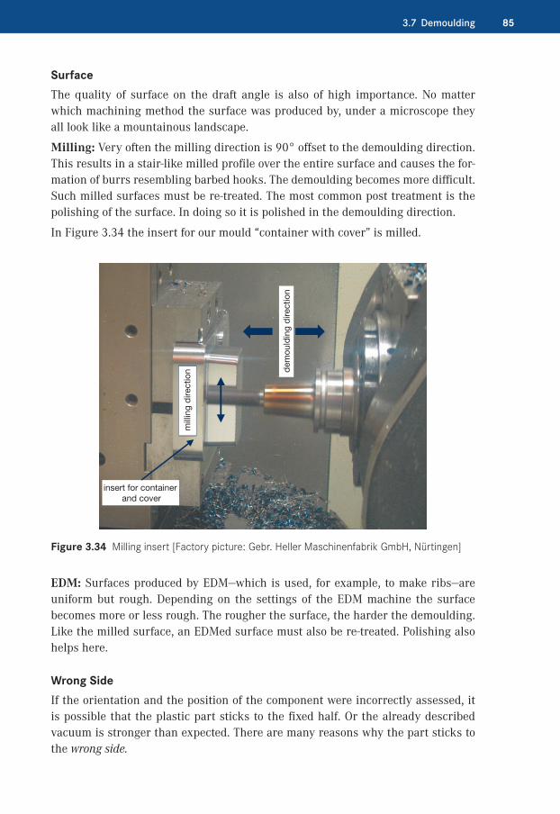
SurfaceThe quality of surface on the draft angle is also of high importance. No matter which machining method the surface was produced by, under a microscope they all look like a mountainous landscape.
Milling: Very often the milling direction is 90° offset to the demoulding direction. This results in a stair-like milled profile over the entire surface and causes the for-mation of burrs resembling barbed hooks. The demoulding becomes more difficult. Such milled surfaces must be re-treated. The most common post treatment is the polishing of the surface. In doing so it is polished in the demoulding direction.
In Figure 3.34 the insert for our mould “container with cover” is milled.
mill
ing
dire
ctio
n dem
ould
ing
dire
ctio
n
insert for container and cover
Figure 3.34 Milling insert [Factory picture: Gebr. Heller Maschinenfabrik GmbH, Nürtingen]
EDM: Surfaces produced by EDM—which is used, for example, to make ribs—are uniform but rough. Depending on the settings of the EDM machine the surface becomes more or less rough. The rougher the surface, the harder the demoulding. Like the milled surface, an EDMed surface must also be re-treated. Polishing also helps here.
Wrong SideIf the orientation and the position of the component were incorrectly assessed, it is possible that the plastic part sticks to the fixed half. Or the already described vacuum is stronger than expected. There are many reasons why the part sticks to the wrong side.

120 3 Preparation
In Figure 3.68 the different filling of both cavities can be seen. The cover fills up sooner than the container. The flow line is shifted further inside the container.
flow line on the container
simulation for 75% filled parts
Figure 3.68 Filling with delay [Simulation: Cimatron GmbH, Ettlingen]
Another very important option results from the time delay control of the needles for very long and thin plastic parts. If these parts are injected uniformly with a hot runner distributor system with for example six open nozzles, five flow lines result. If the same part is filled with needle valve nozzles it could look like this: The first nozzle opens and fills the first portion of the cavity. If the melt front is over the second nozzle, it opens and injects into the flowing melt. This continues until the part is completely filled. The exact procedure must be determined through a filling analysis on the machine. Flow lines are avoided or minimised.
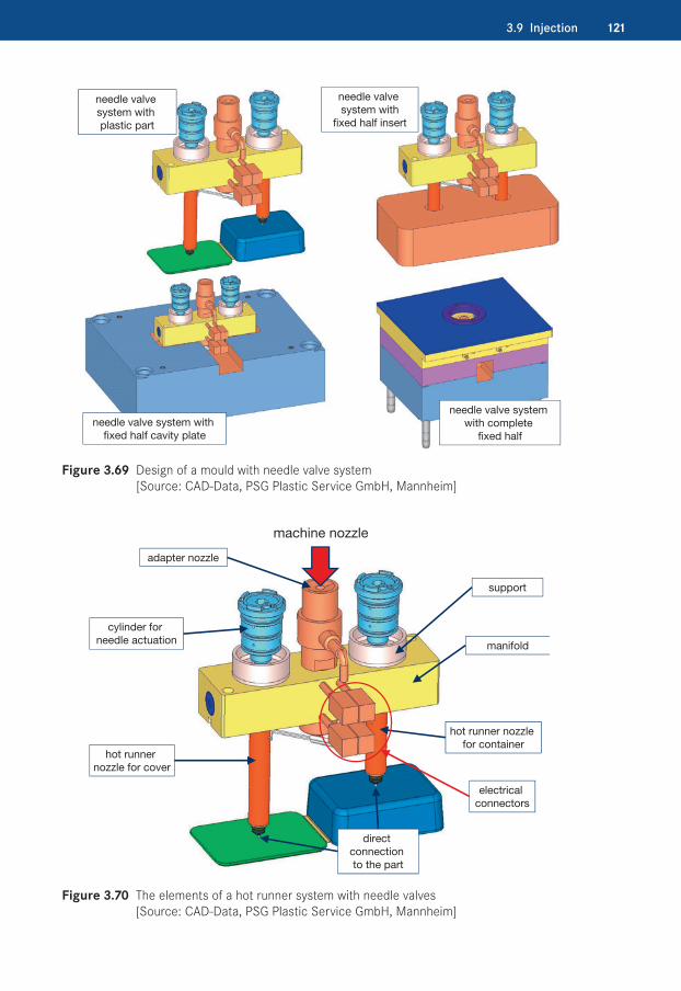
In Figure 3.69 the design of a hot runner system with needle valve nozzles is pic-tured.
In Figure 3.70 the elements of a hot runner system with needle valve nozzles is pictured. The heating is not additionally described here; it is analogous to the manifold in Figure 3.66.
1213.9 Injection
needle valve system with plastic part
needle valve system with
fixed half insert
needle valve system with fixed half cavity plate
needle valve system with complete
fixed half
Figure 3.69 Design of a mould with needle valve system [Source: CAD-Data, PSG Plastic Service GmbH, Mannheim]
cylinder for needle actuation
machine nozzle
hot runner nozzle for cover
adapter nozzle
direct connection to the part
electrical connectors
hot runner nozzle for container
manifold
support
Figure 3.70 The elements of a hot runner system with needle valves [Source: CAD-Data, PSG Plastic Service GmbH, Mannheim]

148 4 Components
4.2.2.2�Split Line on SlideIf the mould contour is on the slide then the split line is circumferential to the mould contour. The split line must be tight but also serve as ventilation.
For the split line on the slide the same rules as for the general split lines in Section 3.8 apply.
There is an additional decisive factor for the slide. The slide or the split line of the slide moves forward and backward in the guiding. The problem there is the level split line at the bottom. With every movement the slide touches the level split line face. Because of the distance it must cover it can be that it moves beyond the edge of the moving half insert. During retraction in the mould the slide runs over the outer edge of the insert with the front edge of the split line. Over time this edge on the slide is damaged and a burr forms.
To avoid this, at this split line there should be a small ramp similar to the draft angle on the side of the slide.
A split line on the slide should always be designed so that at the last moment of closing the injection mould it has contact with the opposite side. During opening it is reversed: it should be immediately free. Split lines that slip along the opposite side will not last very long.
In Figure 4.12 two slides from our container are displayed. On the big slide a circumferential split line is drawn. The inclined ramps are seen at the bottom of both slides.
In Figure 4.13 the real situation is shown on the injection mould. The lead-in cham-fer is shown on the slide and in the insert. The slide has first contact with the insert when the injection mould is totally closed.
The same applies for slides which are installed on the lower half of the mould split line. Such a slide, in addition to the inclined ramp below (see Figure 4.12), also needs a lateral ramp or lead-in chamfer. Through this lateral lead-in chamfer the split line between the slide and the insert is sealed. Because of the inclined split line, the slide has first contact with the insert just before the slide is in the first end position. On our container with cover from the integral hinge section there is now a lateral catch which must be demoulded below the main split line. The catch is an undercut and therefore needs a slide.

1494.2 Slides
split lines, circumferential on the mould contour
draft so that the slide does not scuff
Figure 4.12 Slides with split lines and ramps
lead-in chamfer on the slidelead-in chamfer for the slide
Figure 4.13 Slide and insert with lead-in chamfer [Factory picture: Formenbau Rapp, Löchgau]
In Figure 4.14 the lateral ramp and the ramp below are shown. Also for this slide it is important that the contact between the slide and the insert takes place at the very last moment.

206 4 Components
4.6.3�Graining
A treatment proven for decades to generate a structured surface on plastic parts is graining, or texturing, by etching. With this procedure a variety of surfaces can be produced, such as leather appearance, textile appearance, geometrical structures or also EDM structure.
For graining by etching, the inserts or cavity plates with mould contours are covered on all points which should not be textured with an acid resistant adhesive. The desired texture is inserted as a foil in the mould contour and covers the rest of the parts. The acid etches the clear areas. The textured surface is cleaned and sandblasted. The foils are inserted again etching and sand blasting is repeated. The procedure is repeated several times until the final structure is achieved. The covered positions are freed again and the mould is finished. What is here relatively simply described is actually a complicated and elaborate process which demands time.
Since these structures are very deep the rules for the draft angle must be noted.
In Figure 4.63 a leathery texture and a grained EDM texture, which is generally known, are shown.
leather structure
grained EDM structure
Figure 4.63 Different grained textures [Source: Reichle GmbH, Bissingen-Teck]
232 6 Further Knowledge
Example: SurfaceAnother example is the surface of the plastic part. As described in Section 4.6, the type of surface must be clarified with the customer at the beginning of the work.
Depending on the surface the preliminary work must be adjusted accordingly. If the surface is EDMed later, not too much effort and time are required in finish- milling.
If the surface is mirror polished subsequently, the EDMed surface is not a good working surface. Through EDM the microstructure on the surface is changed. Dur-ing high gloss polishing this EDM scale must be completely removed or otherwise no shiny surface can be produced.
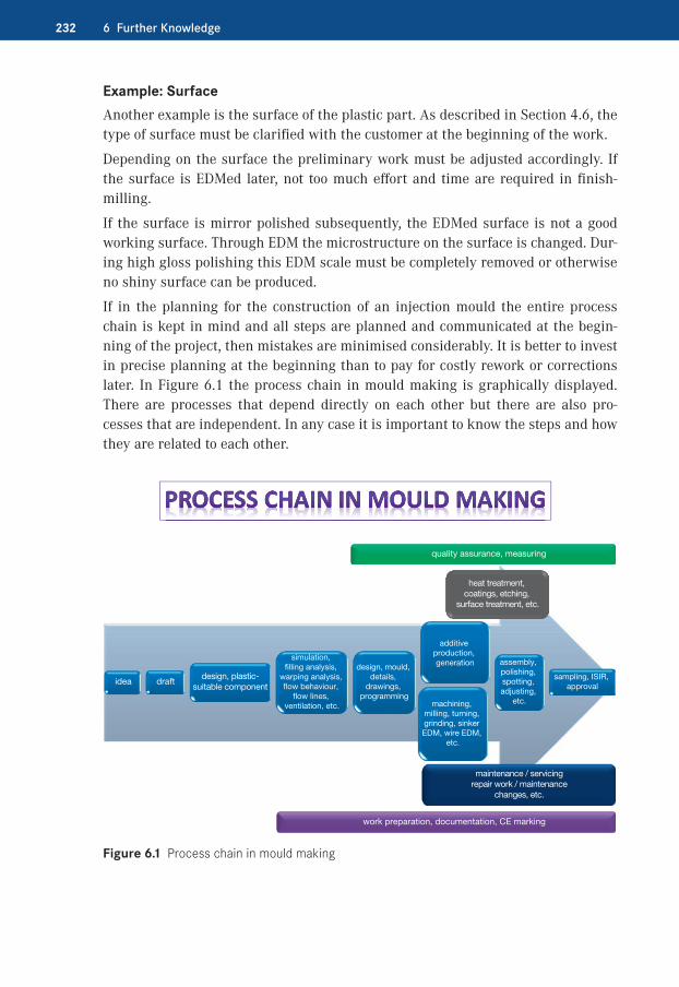
If in the planning for the construction of an injection mould the entire process chain is kept in mind and all steps are planned and communicated at the begin-ning of the project, then mistakes are minimised considerably. It is better to invest in precise planning at the beginning than to pay for costly rework or corrections later. In Figure 6.1 the process chain in mould making is graphically displayed. There are processes that depend directly on each other but there are also pro-cesses that are independent. In any case it is important to know the steps and how they are related to each other.
idea draftdesign, plastic-
suitable component
simulation, filling analysis,
warping analysis, flow behaviour,
flow lines, ventilation, etc.
design, mould,
details, drawings,
programming
additive production, generation assembly,
polishing, spotting, adjusting,
etc.
sampling, ISIR, approval
heat treatment, coatings, etching,
surface treatment, etc.
maintenance / servicingrepair work / maintenance
changes, etc.
machining, milling, turning, grinding, sinker EDM, wire EDM,
etc.
work preparation, documentation, CE marking
quality assurance, measuring
Figure 6.1 Process chain in mould making
2336.2 Quality Assurance
�� 6.2�Quality Assurance
Quality assurance (QA) is more than, for example, checking the quality of an insert or measuring its width. Although this is also a part of quality assurance it is just a small part.
Mission Statement, VisionEvery company should define a mission statement or vision. These are goals the company wants to reach in an agreed time period, usually a calendar year. These goals are different depending on the company. For example, a 5 % increase of turn-over or the reduction of error rate to 0.5 %, increasing the spindle hours in the milling department by 10 %, acquiring new or specific customers, or being active in a new industry, etc.
Achieving these goals must not be left to chance.
Example: Reducing the Error RateLet’s look at the example of reducing the error rate. Errors always involve time and money. It’s not about looking for someone to blame. Possibly a process was defined falsely and could not be processed differently. If an error occurs, different mecha-nisms must be set in motion. What happened, why did it happen, and what can we do to assure it does not happen again?
� What happened? The ejector is too short. � Why did it happen? The measurement carried out with the calliper was incorrect. � What can we do to ensure that it does not happen again? Introduce an audit for measuring equipment or change the testing cycle of the measuring equipment.
� Of course the ejector must be remade but this is only a logical consequence.What is described above must be an automatic process in which the hours, the value, and the costs incurred are determined. If the goal is the reduction of the error rate then the basis for the reduction must be known.
Description of Recurring ProcessesIn mould making, recurring processes and tasks are frequent. To maintain control of a company, it is necessary that the processes or tasks are described. This of course only applies for essential processes. It does not include, for example, how to find the way to the cabinet where the ejectors are kept. A sensible description of a process can for example say: each ejector has to be measured. At the beginning of the work, the measuring equipment must be checked with a gauge or calliper and the result recorded. The ejectors must be labelled; the measured dimensions must be off the list or written down.

234 6 Further Knowledge
The effort for following the process described is not much more than if this work would be excursively done. Even without process, a list of ejectors is needed, the measuring equipment must be available, and the ejectors must be labelled accord-ing to their length.
Assured QualityIf such processes are complied to then quality is ensured over a long period. Qual-ity should never be left to chance.
A very important aspect of quality assurance is that every employee should follow the same process. Thus the quality is consistent and secured for the entire com-pany.
The quality assurance is a live system. Its effectiveness must be constantly reviewed and checked. Insufficient processes must be expanded and too strict guidelines relaxed. Changes of the tasks, the environment, the techniques and so one must be adapted to the changing descriptions and conditions.
Consistent Quality AssuranceThe list of the defining processes and procedures can be continued indefinitely at this point. Starting from the offer of the customer’s ordering process, the process planning, the definition of the individual process steps from the procurement and the production to the dispatch of the product, it is important that the systematic quality assurance is understood.
Often the quality assurance is regarded negatively by a company as an additional cost factor. Of course this approach is wrong. By implementing consistent quality assurance and defining procedures and processes, mistakes are avoided, proce-dures are improved and simplified, and much becomes more transparent and clearer. The costs saved with the right quality assurance are higher than the costs incurred by it.
A company’s success must never be left to chance!
Standards:Different industries require different standards.
� The standard VDA 6.1 is applied in the German automotive industry. � Suppliers who supply parts to the automotive industry, parts for driving vehicles must meet the standards of the ISO/TS 16949.
� The general standard which applies to mould making is the EN ISO 9001:2008. � A guiding principle which must be valid everywhere is:Quality is when the customer comes back and not the injection mould.

2356.3 Fits and Play in the Mould: What Must Fit?
�� 6.3� Fits and Play in the Mould: What Must Fit?
The design of an injection mould is precision work. Precision in mould making not only means accurate adherence to tolerances, but also coordination of components, which must fit among themselves. In mould making there are press fits, loose fits, fits which must run smoothly and free of play, or fits where the parts are assem-bled with a very light hammer strike. The scope includes everything that belongs to the theme precision. The measurable difference between something installed free of play which can be moved manually or something that was built in with light hammer strikes is minimal. The difference between them is only a few μm. Herein-after, the components and their fits or accuracy of fit are described.
Guiding in the PlatesGuide bolts and guide bushes are assembled in the plate with light hammer strikes. It is also not a problem if they are pushed into the holes by hand. However the bush or the bolt must not be installed with hard hammer strikes. It is important that oil is used during every installation. If the bush or the bolt is jammed, the guiding is defective. If the bush is installed too tight in the guide, it could be compressed and then the bolt would not move any more in the guide bush.
Inclined pins can also be installed with a light hammer strike or by hand. They may not wobble or have play. Inclined pins must also absorb radial forces. If they have play, the hole becomes bigger over time and there is always more play, until the inclined pin breaks.
In Figure 6.2 the bushes, bolts, and inclined pins in the cavity plates are shown.
guide bushes guide bolts
inclined pins
Figure 6.2 Guide bushes, guide bolts, and inclined pins
236 6 Further Knowledge
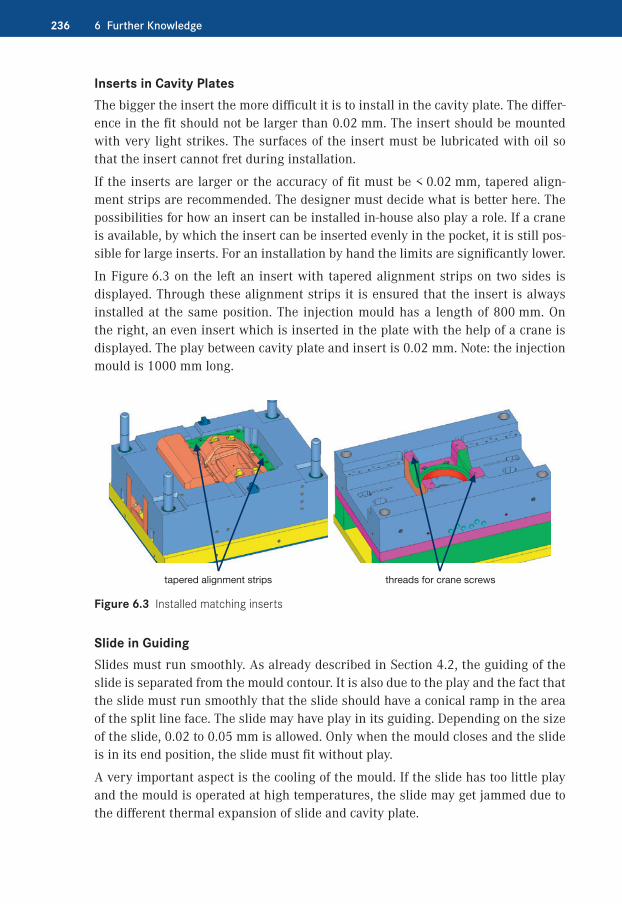
Inserts in Cavity PlatesThe bigger the insert the more difficult it is to install in the cavity plate. The differ-ence in the fit should not be larger than 0.02 mm. The insert should be mounted with very light strikes. The surfaces of the insert must be lubricated with oil so that the insert cannot fret during installation.
If the inserts are larger or the accuracy of fit must be < 0.02 mm, tapered align-ment strips are recommended. The designer must decide what is better here. The possibilities for how an insert can be installed in-house also play a role. If a crane is available, by which the insert can be inserted evenly in the pocket, it is still pos-sible for large inserts. For an installation by hand the limits are significantly lower.
In Figure 6.3 on the left an insert with tapered alignment strips on two sides is displayed. Through these alignment strips it is ensured that the insert is always installed at the same position. The injection mould has a length of 800 mm. On the right, an even insert which is inserted in the plate with the help of a crane is displayed. The play between cavity plate and insert is 0.02 mm. Note: the injection mould is 1000 mm long.
tapered alignment strips threads for crane screws
Figure 6.3 Installed matching inserts
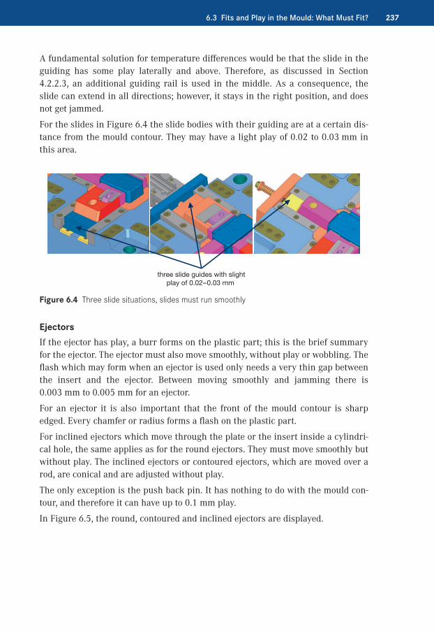
Slide in GuidingSlides must run smoothly. As already described in Section 4.2, the guiding of the slide is separated from the mould contour. It is also due to the play and the fact that the slide must run smoothly that the slide should have a conical ramp in the area of the split line face. The slide may have play in its guiding. Depending on the size of the slide, 0.02 to 0.05 mm is allowed. Only when the mould closes and the slide is in its end position, the slide must fit without play.
A very important aspect is the cooling of the mould. If the slide has too little play and the mould is operated at high temperatures, the slide may get jammed due to the different thermal expansion of slide and cavity plate.
2376.3 Fits and Play in the Mould: What Must Fit?
A fundamental solution for temperature differences would be that the slide in the guiding has some play laterally and above. Therefore, as discussed in Section 4.2.2.3, an additional guiding rail is used in the middle. As a consequence, the slide can extend in all directions; however, it stays in the right position, and does not get jammed.
For the slides in Figure 6.4 the slide bodies with their guiding are at a certain dis-tance from the mould contour. They may have a light play of 0.02 to 0.03 mm in this area.
three slide guides with slight play of 0.02–0.03 mm
Figure 6.4 Three slide situations, slides must run smoothly
EjectorsIf the ejector has play, a burr forms on the plastic part; this is the brief summary for the ejector. The ejector must also move smoothly, without play or wobbling. The flash which may form when an ejector is used only needs a very thin gap between the insert and the ejector. Between moving smoothly and jamming there is 0.003 mm to 0.005 mm for an ejector.
For an ejector it is also important that the front of the mould contour is sharp edged. Every chamfer or radius forms a flash on the plastic part.
For inclined ejectors which move through the plate or the insert inside a cylindri-cal hole, the same applies as for the round ejectors. They must move smoothly but without play. The inclined ejectors or contoured ejectors, which are moved over a rod, are conical and are adjusted without play.
The only exception is the push back pin. It has nothing to do with the mould con-tour, and therefore it can have up to 0.1 mm play.
In Figure 6.5, the round, contoured and inclined ejectors are displayed.
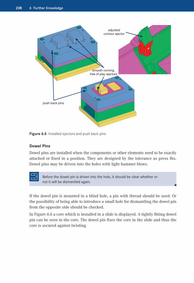
238 6 Further Knowledge
smooth running,free of play ejectors
push back pins
adjustedcontour ejector
Figure 6.5 Installed ejectors and push back pins
Dowel PinsDowel pins are installed when the components or other elements need to be exactly attached or fixed in a position. They are designed by the tolerance as press fits. Dowel pins may be driven into the holes with light hammer blows.
Before the dowel pin is driven into the hole, it should be clear whether or not it will be dismantled again.
If the dowel pin is mounted in a blind hole, a pin with thread should be used. Or the possibility of being able to introduce a small hole for dismantling the dowel pin from the opposite side should be checked.
In Figure 6.6 a core which is installed in a slide is displayed. A tightly fitting dowel pin can be seen in the core. The dowel pin fixes the core in the slide and thus the core is secured against twisting.

2396.4 Heat Treatment
dowel pin with extract thread installed
Figure 6.6 Permanently installed dowel pin
�� 6.4�Heat Treatment
In modern mould making, the heat treatment is an important factor for the success or failure of an injection mould. There are always more new mould steels with their corresponding heat treatments. The quality of the moulds, especially their longevity, is driving this trend.
Nowadays hardened steel blocks are available from material manufacturers. The advantage of these is that the heat treatment has already taken place and one can fully rely on the geometry of the component: there is no warping to be considered because of the geometry. The disadvantage is that, due to the hardness, the subse-quent machining is more complicated and the hardened steel costs more. It must be carefully considered here what is better or cheaper.
As already discussed in Section 6.1 on the process chain, the heat treatment should be considered from the beginning and ongoing in the planning and process prepa-ration of an injection mould. This already begins during the selection of the appro-priate material. The material defines the procedure before, and the procedure defines the material.
Does an insert have to be annealed between one machining step and another because there was an extensive or inhomogeneous machining of the insert or large cavity plate? Are they hardened or nitrided? How is the roughing of an insert done when it is through-hardened, or nitrided? Are there corners, fillets, ribs, etc. con-sidered during the planning? These are questions that need to be considered already during the planning.
240 6 Further Knowledge
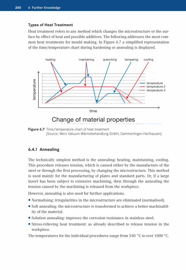
Types of Heat TreatmentHeat treatment refers to any method which changes the microstructure or the sur-face by effect of heat and possible additives. The following addresses the most com-mon heat treatments for mould making. In Figure 6.7 a simplified representation of the time/temperature chart during hardening or annealing is displayed.
heating maintaining quenching tempering cooling
Change of material properties
tem
per
atur
e
time
temperaturetemperature 2temperature 3
Figure 6.7 Time/temperature chart of heat treatment [Source: Werz Vakuum-Wärmebehandlung GmbH, Gammertingen-Harthausen]
6.4.1�Annealing
The technically simplest method is the annealing: heating, maintaining, cooling. This procedure releases tension, which is caused either by the manufacture of the steel or through the first processing, by changing the microstructure. This method is used mainly for the manufacturing of plates and standard parts. Or, if a large insert has been subject to extensive machining, then through the annealing the tension caused by the machining is released from the workpiece.
However, annealing is also used for further applications.
� Normalising: irregularities in the microstructure are eliminated (normalised). � Soft annealing: the microstructure is transformed to achieve a better machinabil-ity of the material.
� Solution annealing: improves the corrosion resistance in stainless steel. � Stress-relieving heat treatment: as already described to release tension in the workpiece.
The temperatures for the individual procedures range from 550 °C to over 1000 °C.
2416.4 Heat Treatment
6.4.2�Hardening
An already old-established method for the hardening of components is carburising or case-hardening. The surface layer of steel with little carbon content is hardened by this method. In the past, components would be placed in a box with a special coal. The box with the mould components went into the hardening furnace and was heated. The carbon transferred from the coal to the component and thus hard-ened the outer surface layer. In modern hardening furnaces carbon in the gaseous state is conducted into the combustion chamber of the furnace during the harden-ing process. In the furnace the entire process of the carburising, quenching, and tempering can be processed in one run. The carburised outer layers have a thick-ness of 0.1 to 4 mm. Steel which is suitable for case-hardening or carburising has a carbon content of 0.1 to 0.3 %.
Steel with more than 0.3 % carbon content is through hardened. The through hard-ening steel is heated under vacuum to a temperature between 800 and 1080 °C depending on the type of material. This temperature is maintained over a defined period depending on material and thickness. Afterwards, it is quenched and tem-pered several times. Depending, again, on material and tempering temperature, the desired hardness is reached. The through hardening steel is not only hardened on the surface but, like the name suggests, a uniform hardness is reached over the entire component. The hardening under vacuum has several advantages. The two most important are the very low warping and the oxidation-free, bright surface. The vacuum hardening is more environmentally friendly compared to the other methods.
As discussed several times, the heat treatment must be planned. This especially applies to vacuum hardening. If this is not the case, it may cause disastrous hard-ening errors. The reason is not the false hardening but the false preparation of the workpiece.
In Figure 6.8, the workpieces which during or after the hardening cracked or be-came deformed and unusable are displayed.
In Figure 6.9 several errors during the preprocessing of the workpiece are displayed. How the workpiece should be properly prepared is also shown.

242 6 Further Knowledge
cross pieces too thin
stress crack
crack because of too thin wall
Figure 6.8 Errors during preprocessing before hardening [Source: Werz Vakuum-Wärmebehandlung GmbH, Gammertingen-Harthausen]
0
risk of cracking
risk of cracking during hardening
high risk of cracking
low risk of crackingunfavourable
unfavourable
unfavourable
unfavourable
unfavourable
unfavourable
unfavourable
unfavourable favourable
favourable favourable
favourable
favourable
favourable
favourable
favourable
favourable
favourable
favourable
favourable
unfavourable
unfavourable unfavourable
risk of cracking
Figure 6.9 Examples of correct and false geometries [Source: Werz Vakuum-Wärmebehandlung GmbH, Gammertingen-Harthausen]

2436.4 Heat Treatment
SteelSteels suitable for vacuum hardening are:
� high-alloyed tempered and mould steel � cold-work and hot-work steel � high-speed steel � powder metallurgical steel � corrosion-resistant steel
In Figure 6.10 the specific material grades and the percentage frequency of use for hardening is displayed.
other
In total over 250 different steels
PM (50 types)
Figure 6.10 Materials for vacuum hardening [Source: Werz Vakuum-Wärmebehandlung GmbH, Gammertingen-Harthausen]
6.4.3�Nitriding
A now common method in mould making is plasma nitriding. During plasma nitriding a nitrogen gas atmosphere is diffused into the surface zone of the work-piece, which is made out of ferrous material. The temperatures during plasma nitriding are at a maximum of 600 °C. Therefore the warping of the workpiece is extremely low. This is also the decisive advantage over the hardening process.
All ferrous materials, including cast iron and sintered material, can be plasma nitrided.
258 7 The Finished Mould
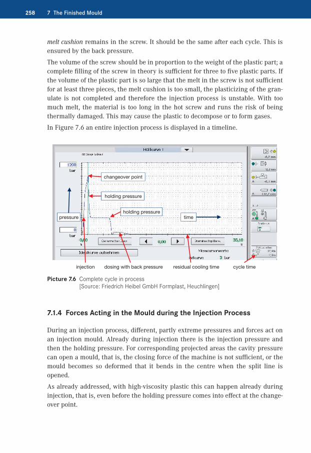
melt cushion remains in the screw. It should be the same after each cycle. This is ensured by the back pressure.
The volume of the screw should be in proportion to the weight of the plastic part; a complete filling of the screw in theory is sufficient for three to five plastic parts. If the volume of the plastic part is so large that the melt in the screw is not sufficient for at least three pieces, the melt cushion is too small, the plasticizing of the gran-ulate is not completed and therefore the injection process is unstable. With too much melt, the material is too long in the hot screw and runs the risk of being thermally damaged. This may cause the plastic to decompose or to form gases.
In Figure 7.6 an entire injection process is displayed in a timeline.
dosing with back pressure
changeover point
pressure
injection
holding pressure
time
residual cooling time cycle time
holding pressure
Picture 7.6 Complete cycle in process [Source: Friedrich Heibel GmbH Formplast, Heuchlingen]
7.1.4�Forces Acting in the Mould during the Injection Process
During an injection process, different, partly extreme pressures and forces act on an injection mould. Already during injection there is the injection pressure and then the holding pressure. For corresponding projected areas the cavity pressure can open a mould, that is, the closing force of the machine is not sufficient, or the mould becomes so deformed that it bends in the centre when the split line is opened.
As already addressed, with high-viscosity plastic this can happen already during injection, that is, even before the holding pressure comes into effect at the change-over point.

2919.6 New Technologies
Compared with the finished (prefabricated) part, a generated core has still some allowance on it so the finished contour can be produced.
The advantages of laser sintering are:
� Time saving: Only a few hours after the design, the core can actually be held in hand, no matter how complex it is.
� Flexibility: Modifications of the design data and production of variants can be integrated in the original process and quickly implemented after a sampling.
� Quality: With the laser more complex moulds can be generated than with tradi-tional methods. This can improve the quality of the products.
� Productivity: The installation of conformal cooling systems in injection moulds enables the reduction of the production cycle times.
� Cost reduction: As a general rule, laser sintered inserts from original material last longer than conventionally produced inserts. In connection with the afore-mentioned factors this results in clear cost benefits.
Figure 9.22 displays a core on the laser machine on the left, with some powdery material on the right of the core. The right shows the finished, mirror polished mould core and the produced plastic parts.
core built in layers metal powder plastic parts finished core
Figure 9.22 Raw material and finished core [Source: bkl-lasertechnik, Rödental]
9.6.2�Vacuum Soldering
Like laser sintering, vacuum soldering belongs to the recent technologies in mould making. The soldering itself is a long-established practice for connecting materi-als. The trend towards conformal cooling was a motivation for the development of this method.
During vacuum soldering several individual parts are soldered together with a solder. In practice it can look like this: many layers of steel are laid one above the other. A soldering foil or solder paste is placed between two layers. Depending on
Symbols
2.5-axis milling 2712-C mould 282-D drawings 433+2-axis milling 2753-axis milling 2723-C or 4-C mould 293-D data 433-D design 434-axis milling 2735-axis machining centre
2705-axis milling 2745-axis simultaneous
hobbing 2765-axis simultaneous milling
276
A
abrasive paper, high- quality 233
abrasive plastics 72adapter nozzle 116additional centring 92additional demoulding
directions 3additional moulding
directions 12air valve 84aluminium 71annealing 240anti-rotation protection 9
aperture 12arrangement 69arrangement of cavities
66assembly 217, 220auxiliary ejector 110auxiliary rib 109
B
backing plate 6, 10“backpack” slide 165baffle 187, 191balancing cavities 254ball-actuated puller 125ball catch 160beryllium copper 196bioplastics 2blade ejector 131, 170blank 29, 199blockings 145bore pattern, corrections
142bubbler 192
C
cable 225CAD – program 43 – system 43
CAD/CAM system 43, 212
CAD data 278CAD model 278CAD system 278CAM programming 278catch 160cavity plate 6cavity pressure 76central clamping 66central ejector 176change core 142changes on an injection
mould 246check lists 295clamping claws 250clamping plate 6, 33claws 86clip lock 14closing force 66, 76cloud 45CNC program 269coatings 245cold runner 101cold runner distributor
103cold runner distributor
cross section 104cold slug 107collapsible core 22, 182colour chart 295complexity of the plastic
part 64connect circuits 197connection 68
Index

304 Index
connectors of components 224
constrained shrinkage 53continuous production 72contour changes 141contoured ejector 173contour-forming split line
face 88controlled needle 118converting 45cool core 141cooling 138, 186 – check for leaks 227
cooling circuits 186cooling circuits, redirect
190cooling connectors 227cooling hole, sealing 139cooling in slide 161cooling system 183cooling time 256copper 204, 283copper alloy 141copper cores 195core pins 10, 11 – fixing 10
core pullers 250corner warping 58costs 14, 18, 64, 114, 117 – determine 247
cotter 75cotter surface 157cup-shaped plastic parts
4cycle 29cycle determined 70cycle time 256cylinders 152
D
data – amount 44
data size 43, 48data transfer 44
date stamp 201dead-end recess 108dead spots 116deep hole drills 288deflection elements 197delay 164demoulding 11, 78demoulding direction 3,
59 – additional 3, 12 – main 3, 11, 167 – second 11 – secondary 4
demoulding problems 83design 43design elements 43de-spindling 22, 23diaphragm gate 112dielectric 282DIN 912 136DIN 16742 53DIN 66217 271, 273direct injection 67displaced air 127distributor 116dome 61, 79dosing 253draft angle in the split 81draft angles 78drilled cooling 188drilling 287durability 135DXF 45
E
economic calculation 65, 117
edge length 18EDM 85, 204EDM scale 92ejection unit 251ejector as tool 174ejector base plate 168ejector bolts 249
ejector cover plate 168ejector for inclined surface
11ejector guiding 126ejector imprints 83ejector pins with ball
heads 124ejectors 15, 61, 83, 167ejector set 6, 15, 168electrode 204end position 13, 92, 159end-position locking 160end-position locking
security 157, 177energy efficiency 251engineer’s blue 222entrapped air 95error quotation 233etched pattern 92etching process 206external thread 19, 20
F
feeder 37feed point 93, 128feed point location 94fibre glass 49fillers 49filling pattern 101filling simulation 95filling study 120, 253film gate 111finishing processing
276finish milling 275fit 219 – accuracy 236
fits 235fitting 198fixed half 3, 6fixing of core pins 10flat plastic parts 4flow line 95, 96, 119forced control 13, 21, 152

305Index
forced demoulding 17, 183forced removal 17forces in mould 258formulas and calculations
296free shrinkage 53ftp server 45
G
gear 35, 38gear rack 22, 24, 27gear wheel 24, 26glass beads 49graining 206graphite 204, 283grease 152grease pockets 152grinding 286guide bushes 6guide nut 24, 26guides 7guide shoe 37, 40guide thread 24guiding 150guiding bolts 7guiding bolts, length
selection 9guiding in injection mould
151
H
hard components 30hardening 135, 241hard-soft 28heat exchange 184heating cartridges 196heat pipes 195heat treatment 239 – types 240
high-helix lead screw 22, 25, 26, 27
high-helix nut 26high-helix thread drive 26
holding pressure 49, 56, 252
hoses 225hot runner 36, 102hot runner distribution
system with needle valve 118
hot runner distributor 116hot runner single nozzle
114hot runner with needle
valve 32hydraulic connectors 227hydraulic cylinder 13, 25,
156, 165hydraulic unscrewing unit
23
I
IGES 45impact wall 108inclined contour ejectors
219inclined ejector 15, 167,
173, 176inclined pin 13, 21, 152,
164inclined pin/cotter sur-
face relationship 155inclined pin, mechanical
154initial sample 260initial sample report 260injection burr 254injection cycle 3injection mould 1injection moulding
machine 1injection pressure 49, 76inserts 11, 135installation 214 – from inside to outside 214
installation height 249
installation height, higher 42
integral hinge 119, 122integral joint 122internal mould pressure
258internal thread 19, 22
J
jet 108jumping split line face
88
L
label on mould 261laser beam welding 265LaserCUSING 290laser sintering 290laser texture 207latch 14leachate 72lifting bridge 250limit switch 224locating ring 249locks 92, 259longitudinal direction 52loose fits 235lubrication 152
M
machine base 37, 40machine size 64, 74machine sprue bush 37main demoulding direction
3, 81, 167maintenance – ongoing 263 – predictive 264
maintenance schedule 263, 296
male connector 225manifold 116

306 Index
manufactured parts 213manufacturing costs 10manufacturing technol-
ogies 269marking 200marking type 201material accumulation 70material pairings 28material selection 48material selection for
injection mould 71measuring pressure 227melt front time 96melting temperature 116melt temperature 256microstructure, changes
240milled profile 85milled structure 203milling 85, 269milling direction 85milling head 275milling machine 271milling paths 280mirror polishing 293mission statement 233motion sequence 3, 40,
251mould contour 12, 147mould core in slides 145mould cores 22, 140mould for thread 19mould halves 7moulding shrinkage 49mould insert – divide 135 – edge 137
mould inserts 135mould locking device 250mould offset 7mould plan 251mould related dimensions
53mould size 18, 19, 74mould split 87
mould temperature 49, 95, 256
mould types 3mould with moveable
elements 11, 22mould with rotary plate
32mould with slides 12moveable components 11moving half 3, 6multi-cavity mould 27, 68multi-component injection
moulds 28, 35
N
NC data 43neutral data format 44nitriding 243non-mould related dimen-
sions 53nozzle radius 249number of cavities 63, 74
O
oblong hole 164offset split 92open/close mould 3opening and closing 37optimising of parameters
256O-ring seal 138, 218, 228output quality 63, 65, 71over injection 66
P
parameter 251pilot drill 288plastic granulates 1plastic parts 1plastic suitable design
60, 78plate thickness 77
pocket bottom 218polishing 85, 208, 293post processor 281post shrinkage 49practical guidelines 295precision 92, 235press fits 235process chain 231production costs 10production cycle, typical
253profile grinding 286projected surface 158pulling ejector 167push back pin 174push-in connection 198pushing ejector 167
Q
quick connect couplers 198, 227
R
ramp 148, 236recycling 94repairs 266replacement parts 264residual cooling time 257resulting movement 13,
15ribs 61, 79, 131right hand principle 273ring gate 113risers 6rotary plate 33rotary table technology
32roughing 275rough surface 203runner 68, 95, 103, 124

307Index
S
sample mould 71, 135screw 252screw cap 19screw coupling 19screwing movement 22,
23screws 6seal 33sealing plug 198sealing point 253sealing slide 35self-locking effect 136semi-finished parts 33sequential function chart
295serial mould 135server 45service life 71set screw 10shear forces 145shifting technology 29shrinkage 48, 60, 95side opening 12silicone 50simulation 56, 94, 95simulation program 56sinker EDM 283sleeve ejector 129, 171slide 11, 20, 75, 89, 144 – split line 148
slide body 150slide design 146slide guide 21, 220slide in slide 163slide lock technology
35slide operation 13, 152slide width 152sliding guides 37smallest draft angle 79soft components 29,
34soft material 29
spacing rollers 77specifications 59spindle drive 26spiral core 193split 87, 222split edges on insert 91split line – visible 91
split line face – contour-forming 88 – jumping 88 – plain 87
split line faces, two 35split line on slide 148split line surface 21spotting 222spotting edge 223spring ejector 172spring in slide 159sprue 67, 68, 93, 106sprue ejector 175sprue length 126sprue line 94sprue on the part 105sprue picker 94, 123sprue system 101sprue type 101stack mould 35, 64stainless steel 73standard parts 211standards 234STEP 44, 46STL 46stress whitening 83stripper plate 178, 183surface 62, 85, 92, 202surface grinding 287surface modelling software
45
T
talc 49temperature balance 115,
117, 183, 257
temperature balance of the mould 49
temperature of the liquid plastic 49
tempering temperature 241
T-guiding 150thermal sensor 224thread halves 20three plate mould 123TIG welding 264tilting rotary table 277TiN coating 245toggle lever 40tolerances 7, 53transfer point 37transport bridge 225transverse direction 52transverse hole 138triangular facets 47tunnel gate 94, 106tunnel gate inserts 126tunnel in the fixed half
106, 107turning 289two-component injection
mould 28two-stage ejector 180two units 29
U
undercut 11, 15, 20unscrewing movement
22unscrewing unit 27USB stick 45
V
vacuum 80, 84, 85, 137vacuum hardening 241vacuum soldering 291validation 231, 249VDI 3400 204, 283

308 Index
ventilation 127, 137, 148, 174, 257
ventilation channel 130ventilation insert 132ventilation in the split 133ventilation on ejector 133ventilation via components
130Vickers hardness 244visible face 62
visible split line 91vision 233visual inspection 228volumetric filling 253
W
wall thickness 7, 49, 56, 57
warping 56, 95
wear 266wear plates 90, 222welding 264weld penetration 264whip gate 126wire EDM 282, 285without damage 61wrong side 85