INFORMATION SHEET # 02 - 2005 (V2 November …...problem that the Nissan Mistral has. Like the...
29
INFORMATION SHEET # 02 - 2005 (V2 November 2018) Page 1 of 29 Nissan Mistral Rear Seatbelt Anchorage/Floor Rust Problem and LVV Modification Solution Introduction: As a follow on to the LVV Loadbar solution to the Nissan Terrano, Land Transport NZ has asked LVVTA to provide a similar solution under LVV Seatbelt Anchorage Standard 175-00(01) for the rust problem that the Nissan Mistral has. Like the Terrano, the Mistral has been required to have a full rear floor replacement carried out if any rust is evident at WoF or entry inspection. This has been achieved, and an alternative cost effective solution is now available for these vehicles under the Low Volume Vehicle Code. This Information Sheet outlines the problem, the solution and the procedures involved. Affected models, as advised by the Imported Motor Vehicle Dealers Association, are: R20 4-door all KR20 3-door not applicable, different floor The Problem: (This is an excerpt from Land Transport NZ Infosheet 1.35 Rev 3, amended slightly for clarity). In models of Nissan Mistral vehicles, the rear floorpan assembly consists of a two-layer (double-skin) panel. The lower layer is a reinforcing panel spot-welded to the upper layer floor section. The Nissan Mistrals have a rear seat with three seating positions. Situated in the rear floor, are: • two stressed seat anchorages beneath the seat; and • two seatbelt anchorages in the wheel arches beside the rear seat. If moisture gets trapped between the two layers of the floorpan, corrosion can occur around the seat or seatbelt anchorages. Corrosion can also occur where the under-floor reinforcing panel overlaps the top floor skin. A WoF inspector is required by Land Transport NZ to lift the rear seat to examine this area effectively. It is important to note that damage may be more extensive than is first apparent. Indicators of more extensive corrosion may be: • bubbling of the paint or surface irregularities such as swelling between spot welds in the top floor skin or paint; or • a patch repair that has rust around it; or • separation of the reinforcement panel and the top skin; or • discoloration or rust stains at the edges of the reinforcement panel; or • rust holes.
Transcript of INFORMATION SHEET # 02 - 2005 (V2 November …...problem that the Nissan Mistral has. Like the...

INFORMATION SHEET # 02 - 2005 (V2 November 2018)
Page 1 of 29
Nissan Mistral Rear Seatbelt Anchorage/Floor Rust Problem and LVV Modification Solution
Introduction:
As a follow on to the LVV Loadbar solution to the Nissan Terrano, Land Transport NZ has asked
LVVTA to provide a similar solution under LVV Seatbelt Anchorage Standard 175-00(01) for the rust
problem that the Nissan Mistral has. Like the Terrano, the Mistral has been required to have a full
rear floor replacement carried out if any rust is evident at WoF or entry inspection. This has been
achieved, and an alternative cost effective solution is now available for these vehicles under the Low
Volume Vehicle Code. This Information Sheet outlines the problem, the solution and the procedures
involved.
Affected models, as advised by the Imported Motor Vehicle Dealers Association, are:
R20 4-door all
KR20 3-door not applicable, different floor
The Problem:
(This is an excerpt from Land Transport NZ Infosheet 1.35 Rev 3, amended slightly for clarity).
In models of Nissan Mistral vehicles, the rear floorpan assembly consists of a two-layer (double-skin)
panel. The lower layer is a reinforcing panel spot-welded to the upper layer floor section.
The Nissan Mistrals have a rear seat with three seating positions. Situated in the rear floor, are:
• two stressed seat anchorages beneath the seat; and
• two seatbelt anchorages in the wheel arches beside the rear seat.
If moisture gets trapped between the two layers of the floorpan, corrosion can occur around the
seat or seatbelt anchorages. Corrosion can also occur where the under-floor reinforcing panel
overlaps the top floor skin.
A WoF inspector is required by Land Transport NZ to lift the rear seat to examine this area
effectively. It is important to note that damage may be more extensive than is first apparent.
Indicators of more extensive corrosion may be:
• bubbling of the paint or surface irregularities such as swelling between spot welds in the top
floor skin or paint; or
• a patch repair that has rust around it; or
• separation of the reinforcement panel and the top skin; or
• discoloration or rust stains at the edges of the reinforcement panel; or
• rust holes.

Page 2 of 29
The primary safety concern is that corrosion in the rear floor pan area may affect the rear lower seat
and seatbelt anchorage points. Up until now, entire central floor section replacement together with
reinforcer plate replacement has been required (even for discoloration or rust stains, or if rust patch
repairs have been carried out in the floorpan).
One principal difference between the Terrano and the Mistral is that the wheel arches are prone to
rusting also, in the area to which the lower outer seatbelt anchorages are attached.
The cost for this repair process, combined with the repair certification process, can be up to $6,000.
The Low Volume Solution:
LVVTA has, from September to December of 2004, with input from expert hot rod builders, LVV
certifiers, panel repairers, repair certifiers and consulting engineers, developed a modification
known as the “LVVTA Rear Floor Load-bar Seat & Seatbelt Anchorage Reinforcement System” or
“LVV Seat & Seatbelt Anchorage Load-bar” for short. This LVV Seat & Seatbelt Anchorage Load-bar is
designed (after patch repairs, rust treatment and anti-corrosive paint application have been carried
out to the floor and reinforcer) to attach to the underside of the vehicle by plug-welding to both the
reinforcer and the floor section of the vehicle.
The load-bar is designed to spread any load that the seat and seatbelt anchorages may be subjected
to in an impact over a huge area of floor surface and into the wheel arches, and importantly, over a
floor surface area and wheel-arch that is unaffected by the vehicle’s rust problem.
This modification is recognised by the Land Transport NZ as requiring LVV certification under the
Compliance Rule 35001/1 and is legally able to be used as an alternative to the full floor
replacement. A memo dated 16 April 2004 from Land Transport NZ is attached to the back of this
Information Sheet that may be used as evidence to entry certifiers and warrant of fitness issuers that
this modification has been approved
The following important points should be noted:
• This procedure may be applied to all affected vehicles both at entry certification and in-service. Note that for entry-certification vehicles, the VCC should call for a repair certifier to be involved in the process as well, to ensure that the load-bar modification has been carried out and that any other rust or damage has been dealt with.
• In order to maximise the quality of the job and minimise costs to the vehicle owner, the modification should be undertaken by someone whom the LVV Certifier can recommend to the vehicle owner. This should be a tradesman repairer experienced in modern vehicle repair, although an individual who does not meet this criteria can still carry out the modification provided that competence and welding skill can be demonstrated to the LVV Certifier in accordance with NZHRA Tech Bulletin #3.
• This modification can be LVV certified by any LVV Certifier holding Category LVV 1C –‘Modified Production – Structures’.
• Note that clause 1.1(3) of the LVV Certifier Operating Requirements Schedule that requires Land Transport NZ approval of inspection premises used for LVV Certification does not apply in this case.
Page 3 of 29
• Each affected vehicle must be modified and LVV certified according to the following procedure, using LVV Formset FS032.
• Only LVV Seat & Seatbelt Anchorage Load-bars supplied by LVVTA and marked with the LVV logo may be used for this modification and LVV certification process. These LVV load-bars may be ordered by phoning the LVVTA office on (04) 238 4343. These are made to order so please allow additional time for this. For an up to date costing please contact the LVVTA office.
• The 3-door KR20 Mistral has a different floor structure and the LVV Mistral Seat & Seatbelt Anchorage Load-bar will not fit. The only current option for rust in the floors of the 3-door Mistral is full floor replacement.
Note that the photographs in this procedure may be viewed and printed via the LVVTA website (
www.lvvta.org.nz ), and are much clearer in colour.
A copy of the following “Load-bar Modification & LVV Certification Procedure (Nissan Mistral)”
(pages 4-29) should be provided to the panel-repairer with whom you are working.
Nissan Mistral Load-bar Modification & LVV Certification Procedure:
All parts of this procedure apply to the repairer, except those shown in bold, which apply to the LVV
Certifier. The LVV certifier is responsible for the control of the quality of the total process.
Automotive products that must be used in this process are:
• Corrosion Converter – a liquid that neutralises any remaining rust after panel clean-up.
• Automotive Epoxy Primer – an automotive epoxy product, which should be lightly, but thinly applied in sufficient quantity for a change in colour of the surface being coated to be evident. The epoxy-coated surfaces can be handled and over-coated for welding once touch-dry, which (depending on the brand of product) is usually about 1 hour at 20 deg C, or 30 minutes using infra-red lamp heating.
• Weld-through Primer – usually a spray-can product with a visible colour, and conducting properties to allow easy welding. The active ingredient in weld-through primers is zinc or copper, which protects the edge of the finished weld. The primary function of weld-through primer is to melt into the edge of welds. Weld-through primers do not offer a high level of corrosion protection when used alone, compared with epoxy primer, and are normally over-coated with epoxy primer.
• Automotive Urethane Seam Sealant – an edge-sealing product.
• Underbody Protective Coating – a final underbody coating of black rubber/plastic compound.
Reinforcing plate removal
1) Remove the rear seats, seatbelts, trim, and carpet from the central floor section of the vehicle. Two bolts are removed from each of the stressed seat mountings (Photo A).
2) Identify the two seatbelt mounts in the wheel-arch area (Photo B).
3) Undo all body mount bolts holding the body to the chassis and remove the rear six bolts completely. Lift the back of the body away from the chassis by about 60 mm, and support the rear of the body in the raised position with some timber blocks or other appropriate material.
Page 4 of 29
(This is to provide enough room to remove the reinforcing plate through the wheel-arch opening) (Photo C). Note the clip holding the chassis-mounted rear bumper will pop out when the body is raised.
4) From inside the vehicle, remove all the interior floor coating from underneath the seat area (Photo D), back to the floor join seam just behind the cargo hooks (visible in photo S).
5) Using a wire-wheel, strip to bare metal the area underneath the seat area to reveal the spotwelds.
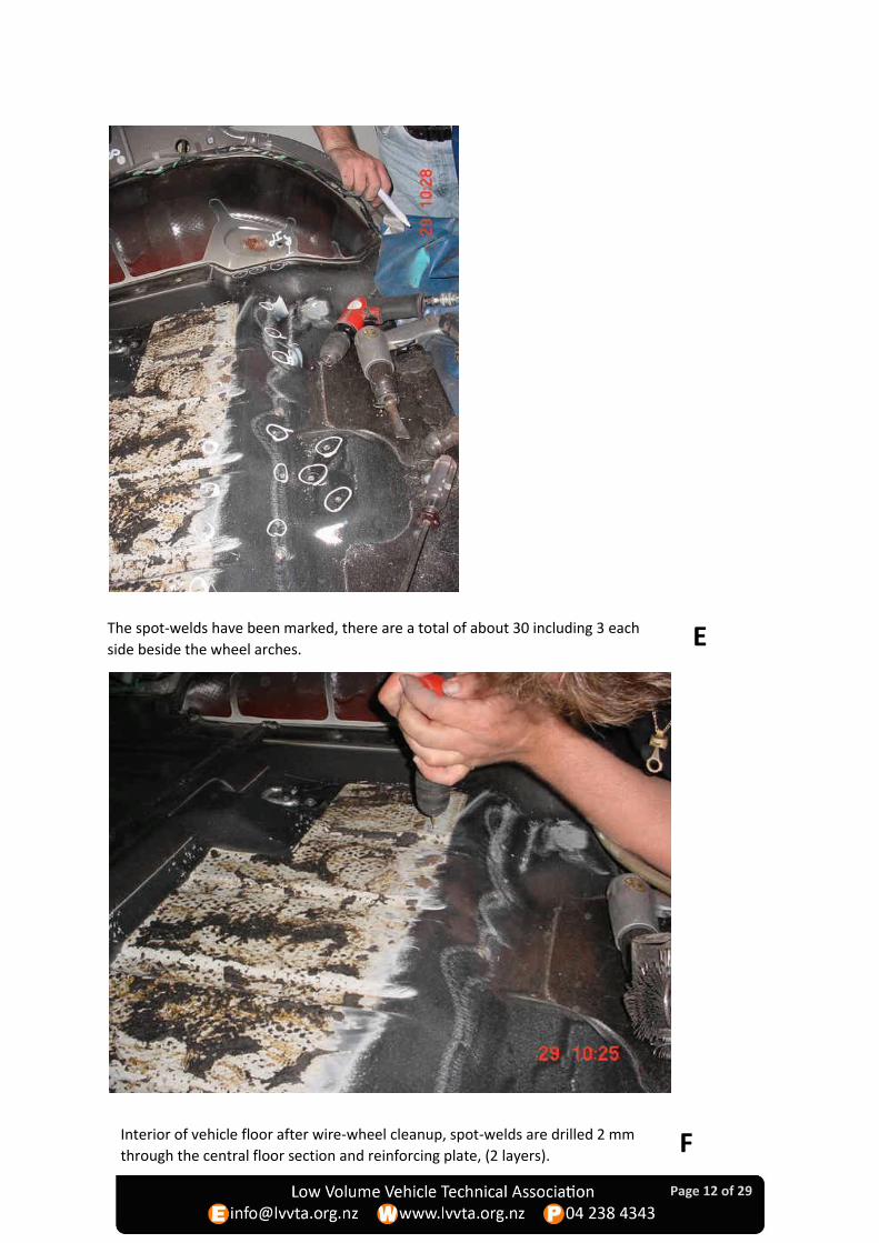
6) From inside the vehicle, identify 30 spot-welds in the rear floor section that attach the reinforcing plate to the central floor section. (Photo E) Drill all spot-welds through the centre of the spot-weld, through both the rear floor section and the reinforcing panel using (approximately) a 2 mm (1/8”) drill-bit. This is followed by an 8 mm or 8.5 mm (5/16”) drill through the central floor section (1 layer only) to remove the spot-welds. (Photos F, G). (These holes are now prepared and ready for plug-welding the complete reinforcing-plate and load-bar assembly back together at the end of the process). Note the three spot-welds beside each wheel-arch (visible by the arrow to the right of the drill in photo G), these are used in step 36.
7) From the outside of the vehicle, in the wheel-arch area, clean the area under the seatbelt anchorage plate back to bare metal using a wire-wheel, then drill through the three spot-welds attaching each end of the reinforcing plate to each wheel-arch panel. Drill right through the bodywork and reinforcing plate (2 layers) using a 2 mm drill bit (1/8”). (Photo H).
8) From the outside of the vehicle, in the wheel-arch area, using a 2 mm drill bit (1/8”), drill through the three spot-welds attaching each seatbelt anchorage plate to the wheel-arch panel. Drill right through the anchorage plate and the bodywork (2 layers) (Photo I).
9) Complete the removal of the three spot-welds in the wheel-arch area attaching each end of the reinforcing plate to each wheel-arch panel by using an 8 mm drill (5/16”) through one layer only (Photo I). (The bodywork containing these three holes is removed in steps 17 and 18).
10) Complete the removal of the three spot-welds in the seatbelt anchorage plate by using an 8 mm drill (5/16”) through one layer only. Remove the seatbelt anchorage plate. (Photo I).
11) Use a lever to ensure all spot-welds have been removed, and manoeuvre the reinforcing plate out from under the vehicle, through the vehicle’s left-side wheel-arch. (Photos J & K).
12) Thoroughly inspect both sides of the reinforcing plate and the central floor section. The LVV certifier is to inspect the reinforcing plate and the central floor section, record their condition, and determine with the repairer whether the reinforcing plate and the central floor section can be economically and safely patch-repaired prior to Load-bar installation. [Note: - the LVV certifier may at his discretion delegate this step to the repairer if he has developed confidence in the repairer’s competence and integrity during a working relationship].
Note that during the visual inspection of both the top and bottom of the central floor section,
scratching and sanding should be carried out as necessary, to ensure no attempts have been
made to cover or disguise any rust or previous repairs.

Page 5 of 29
If there is not a consensus between the repairer and the LVV certifier that the reinforcing plate
and the central floor section can be economically and safely patch-repaired, the LVV Load-bar
modification must be abandoned and full floor replacement must be undertaken instead. The
LVVTA website www.lvvta.org.nz should be referred to for examples of floors and reinforcing
plates that should be rejected.
13) If present, thoroughly inspect any previous localised patch repairs. Any previous localised patch-repairs that have not been carried out to a tradesman-like standard, incorporating good weld quality, must be cut out and replaced with patch-repairs to a tradesman-like standard.
Rust removal, treating and repairs
14) The spot-welds holding each of the two seat anchorage plates (Photo L) on the underside of the reinforcing plate are drilled through 2mm (both layers) then 8 mm through the seat anchorage plate only (1 layer). Remove, and clean-up by wire-wheel, grinding, disc-sanding or sandblasting to a bright steel condition.
15) If rust holes or heavy pitting are present on the seat anchorage plates, discard and make similar plates from 30 mm x 3 mm flat-bar or other suitable material that meets all applicable requirements of LVVTA Seat Anchorage Standard 185-00{00}.
16) Using a cut-off wheel, remove the two downturned ends on the reinforcing plate that were attached to the wheel-arch panel, retaining the cut off pieces (Photo M).
17) Using the ends cut off in step 16, mark out the shape to be cut out of the wheel arch lip, where this extends below floor level (Photo N).
18) Using a cut-off wheel, cut out the marked section in the wheel-arch, flush with the floor. Angle the cuts at about 45 degrees to avoid any sharp edges remaining (Photo O).
19) Where rust-holes or excessively heavy rust-pitting are present in either the wheel arch area or the central floor section, carry out localised patch-repairs to a tradesman-like standard. Patch repairs must be carried out by an experienced and skilled trades-person using a MIG-welder, applying a continuous butt-weld (no overlaps) (Photos P & Q). Cut out and patch repair any rusted areas in the reinforcing plate (Photo R).
20) Thoroughly inspect any joins where the central floor section attaches to any other floor or wheel-arch sections for any rust-heave, discoloration or staining. Where this is visible, open up these joins, clean-up, rust-treat with an automotive corrosion-converter, apply an automotive epoxy primer and re-weld (using weld-through primer) (Photos S & T).
21) Remove any visible signs of rust-pitting, bubbling, discoloration or rust-staining by wire-wheel, grinding, disc-sanding or sandblasting on both the topside and the underside of the reinforcing plate, back to a clean bright-steel condition (Photo U). Ensure that all of the area on the reinforcing plate that the load-bar will overlap is also cleaned back to bright steel.
22) Coat both sides of the reinforcer plate with corrosion converter/epoxy primer. After it has dried, apply a coating of weld-thru primer (Photos V, W).
23) Clean-up the two seat anchorage plates to bare metal, coat with corrosion converter/epoxy primer. After it has dried, apply a coating of weld-thru primer.

Page 6 of 29
24) Clean-up the two wheel-arch seatbelt anchorage plates to bare metal, coat with corrosion converter/epoxy primer. After it has dried, apply a coating of weld-thru primer.
25) Coat the LVV Seat & Seatbelt Anchorage Load-bar with weld-thru primer where it faces the reinforcer plate (Photo X).
Joining of reinforcing plate, LVV Seat & Seatbelt Anchorage Load-bar, and seat anchorage plates
26) After the primers have dried to a handleable condition, position the LVV Seat & Seatbelt Anchorage Load-bar against the underside of the reinforcing plate. Position the two seat anchorage plates to the underside of the LVV Seat & Seatbelt Anchorage Load-bar over their pre-drilled seat anchorage holes. Temporarily clamp the LVV Seat & Seatbelt Anchorage Load-bar and the reinforcing plate together, and the two seat anchorage plates into place using the seat anchorage bolts, ensuring a firm close-contact fit between the LVV Seat & Seatbelt Anchorage Load-bar and the reinforcing plate. (Photo Y)
27) Plug-weld the LVV Seat & Seatbelt Anchorage Load-bar to the underside of the reinforcing plate through the pre-drilled holes in the LVV Seat & Seatbelt Anchorage Load-bar, and plug-weld the seat anchorage plates to the underside of the LVV Seat & Seatbelt Anchorage Load-bar. (Photo Z). Stitch-weld around the cutout at each end. (Note: - where any difficulty is encountered in achieving a firm close-contact fit between the two surfaces, this may be resolved by tapping and the intermittent stitch-welding of the edges of the LVV Seat & Seatbelt Anchorage Load-bar to the reinforcing plate to close up any gaps).
Small stitch-welds are encouraged, in order to prevent moisture or debris from entering any
gaps between the two surfaces during the life of the vehicle.
28) After appropriate cleaning and preparation of welds and heat affected areas, apply an automotive epoxy primer to all plug-welds and any stitch-welds on both the topside and underside of the reinforcing plate, the LVV Seat & Seatbelt Anchorage Load-bar, and the two seat anchorage plates.
29) After the automotive epoxy primer has sufficiently set to a handleable condition, apply weld-through primer to the areas on the topside of the reinforcing plate, which will be plug-welded to the underside of the central floor section.
30) Apply automotive urethane seam sealant to all edges where the LVV Seat & Seatbelt Anchorage Load-bar mates with the reinforcing plate. (Photo AA)
Reinstallation of the reinforcing plate and load-bar assembly
31) In the interior of the vehicle, remove any bead of sealer along the join between the floor and the wheel arch, and weld the joint between the floor and the wheel-arch cutout. It may be easiest to weld this from inside the vehicle. Clean-up the welds, coat with corrosion converter/epoxy primer, after it has dried apply weld-thru primer to this area. (Photo AB)
32) From underneath the vehicle, (Photo AC), remove any visible signs of rust-pitting, bubbling, discoloration or rust-staining by wire-wheel, grinding, disc-sanding or sandblasting on the central floor section, back to a clean bright-steel condition.

Page 7 of 29
33) Coat the cleaned-up underside bare metal with corrosion converter/epoxy primer. After it has dried, apply a coating of weld-thru primer (Photos AD, AE).
34) The LVV certifier is to inspect the completed plug-welded LVV Seat & Seat Anchorage Load-bar & reinforcing plate assembly, and the two seatbelt anchorage plates, before the assembly is reinstalled into the vehicle, and record his approval on the appropriate section of LVV Formset FS032.
35) Slide the finished LVV Seat & Seat Anchorage Load-bar and reinforcing plate assembly from the left side of the vehicle back through the wheel-arch to the central floor section, and temporarily clamp into place with the seat anchorage bolts. Jam the edges in the wheel arch area with wooden blocks to ensure close contact with the floor (Photo AF).
36) From inside the vehicle, weld the three plug-welds through the central floor section at the base of the wheel arch area on both sides. These ensure that the load-bar assembly does not bend downwards during step 37.
37) In each wheel arch, bend up the “ears” of the load-bar by hand, then achieve a close fit by using a length of wood and a hammer. Check the alignment of the seatbelt anchorage bolt-holes (Photo AG).
38) In each wheel-arch, apply weld-thru primer to the load-bar “ears” and fit the seatbelt anchorage plate, locating it centrally. Fit and tighten the seatbelt anchorage bolts (Photo AH).
39) From underneath the vehicle, drill sixteen 2 mm (1/8”) holes through the floor, using the sixteen pre-cut pilot holes in the LVV Seat & Seatbelt Anchorage load-bar (Photo AI).
40) From inside the vehicle, open out the sixteen 2 mm holes drilled in step 39 to 8 mm (5/16”). Drill through the floor only (1 layer), these holes are now ready for plug-welding (Photo AJ).
41) If necessary in order to further achieve a firm close-contact fit between the LVV Seat & Seat Anchorage Load-bar & reinforcing plate assembly and the central floor section, some PK screws and panel washers can be temporarily installed to pull the sections together. Plug-weld all holes in the vehicle’s interior where the reinforcer-plate was drilled out, and the sixteen holes drilled in step 40. (Tip: using an airgun to cool the weld immediately after each plug-weld minimises the flame damage to the coatings underneath each plug-weld).
42) Plug-weld all holes in each wheel-arch area, including the three holes in the seatbelt anchorage plates and stitch-weld around the “ears” of the LVV Seat & Seat Anchorage Load-bar (Photo AK).
Final assembly and treatments
43) Clean-up and grind smooth all plug-welds and apply final automotive epoxy primer to plug-welds and to any patch-repairs on the topside of the central floor section. Check, clean-up and apply final automotive epoxy primer to any affected underside areas also.
44) From underneath the vehicle, seal any joins on the underside of the vehicle’s central floor section using automotive urethane seam sealant (Photo AL). This is to include around the full perimeter of where the reinforcing plate/load-bar assembly mates with the central floor section.
Page 8 of 29
Note that this sealing has not been carried out yet in Photo AL. The visible sealant in this photo
is from Step 30.
45) From underneath the vehicle, apply an underbody protective coating to the LVV Seat & Seatbelt Anchorage Load-bar & reinforcing plate assembly, the underside of the central floor section and the wheel-arch area. Apply final interior coating to topside of the central floor section (Photo AM).
46) Lower the body back down and re-bolt it to the chassis. Re-install the rear seats, and re-install the seatbelts, applying the correct torque to the seatbelt anchorage bolts. These settings can be found in LVV Seatbelt Anchorage Standard 175-00. Refit the rear bumper clips.
47) The LVV certifier is to inspect the completed LVV Seat & Seatbelt Anchorage Load-bar modification and record his approval on the remaining sections of LVV Formset FS032.
48) The LVV certifier is to fill out the ‘base formset’ recording ‘LVVTA REAR FLOOR LOAD-BAR SEAT & SEATBELT ANCHORAGE REINFORCEMENT SYSTEM’ in the ‘CONSTRUCTION/New Seatbelt Anchorages’ section of the FS012 (data sheet).
49) The LVV certifier is to forward the ‘base’ formset together with the FS032 Formset to the Land Transport NZ plate administrator with the normal LVV Compliance Plate fees.
Note that for entry certification of Nissan Mistrals, the scope of the LVV Certification procedure is
limited to the rust in and associated with the central floor section. Any other structural rust in the
vehicle that has been rejected by the entry-certifier (TSDA) or AVIC should be repaired to a
tradesman-like standard by the repairer following the same principles for patch-repairing, treating
and coating as specified for the localised patch repairs in this procedure, however this will need to
be carried out in consultation with a Repair Certifier.
Note that any rust repair work other than to the central floor section and reinforcing plate is a
customer service unrelated to the LVV Seat & Seatbelt Anchorage Load-bar Modification process and
should be treated as a separate contract with the vehicle owner.
Also note that a Repair Certifier is not responsible in any way for assessment of the LVV Load-bar
modification, other than to establish that it is present and the LVV Compliance Plate has been fitted.
Attachments:
• LTSA Memo dated 16th April 2004
• Land Transport NZ Infosheet 1.35 Rev 3
• Survey Sheet FS032 Issue #1, December 2004
• Mistral Load-bar Order Form for LVV Certifiers
If you have any queries or require any further clarification relating to this Information Sheet, please
feel free to contact the Tech team at the LVVTA office on (04) 238 4343.

Page 9 of 29
Tony Johnson
Chief Executive Officer Low Volume Vehicle Technical Association, Inc

Page 10 of 29
Mistral floor, inside vehicle, remove two bolts from each seat mount.
View of the seatbelt anchorage in the wheel arch, from inside the vehicle B
A

Page 11 of 29
Lift the body from the chassis after removal of the 6 body mounting bolts. Note the rear
bumper clip will pop out as the bumper is chassis mounted. C
Remove the interior floor coating from underneath the rear seat area. D
Page 12 of 29
E
Interior of vehicle floor after wire-wheel cleanup, spot-welds are drilled 2 mm
through the central floor section and reinforcing plate, (2 layers). F
The spot-welds have been marked, there are a total of about 30 including 3 each
side beside the wheel arches.

Page 13 of 29
From inside the wheel arch, drill a 2 mm hole through each of three spot-
welds below the seatbelt anchorage, through the wheel-arch panel and the
reinforcing plate (2 layers), followed by 8 mm through the wheel-arch panel
only (1 layer). Note: the seatbelt anchorage plate would normally still be
present (see next picture I).
G Drill each spot-weld with an 8 mm drill bit (5/16”) through the floor only (1 layer). The
holes are now prepared and ready for later plug-welding.
H
Page 14 of 29
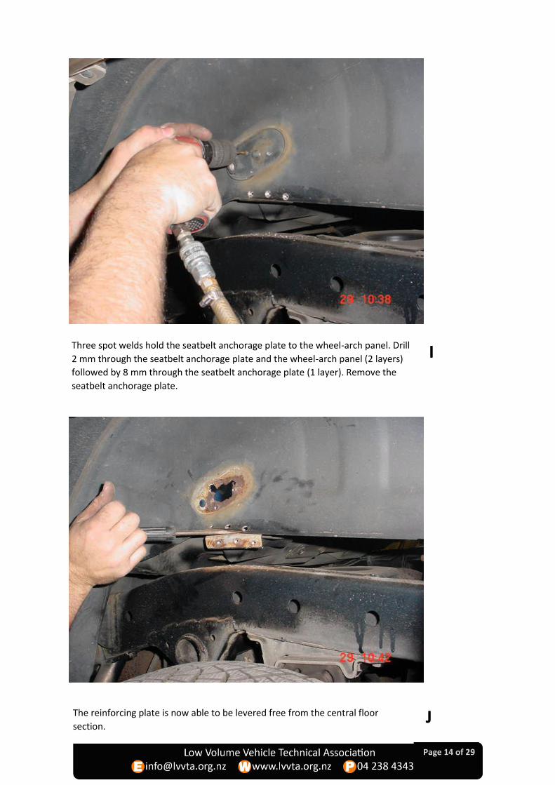
Three spot welds hold the seatbelt anchorage plate to the wheel-arch panel. Drill
2 mm through the seatbelt anchorage plate and the wheel-arch panel (2 layers)
followed by 8 mm through the seatbelt anchorage plate (1 layer). Remove the
seatbelt anchorage plate.
I
The reinforcing plate is now able to be levered free from the central floor
section. J

Page 15 of 29
The spot-welds holding the two seat anchorages to the reinforcing plate are
drilled through 2mm (both layers) then 8 mm through the seat anchorage plate
only (1 layer). Remove the two plates.
K Withdraw the reinforcing plate out the left side of the vehicle.
L

Page 16 of 29
Grind off the two downturned ends on the reinforcing plate. Keep them for
use as templates (see photo N).
M
Using the cutoff ends as templates, mark the shape to cut out of the wheel
arch lip, to bring it flush with the floor.
N

Page 17 of 29
The wheel arch panel has been cut flush with the floor.
Cut out and patch repair (if necessary), the wheel arch seatbelt anchorage
area.
O
P

Page 18 of 29
Cut out and patch repair (if necessary), any rust damage in the floor.
Cut out and patch repair (if necessary), any rust damage in the reinforcing plate.
Q
R

Page 19 of 29
T
Check the front floor seam (arrowed) under the carpeting at the rear of the front
seat. Look for rust bubbling under the coatings. Repair if necessary.
Check the rear floor seam under the carpeting at the front of the cargo area. Look for
rust bubbling under the coatings as in this picture. Repair if necessary.
S

Page 20 of 29
Clean up the reinforcer plate to bare metal using a grinder and/or wire wheel.
Apply corrosion converter/epoxy primer to all bare metal on the reinforcer
plate.
U
V

Page 21 of 29
Turn the reinforcing plate over and lay the LVV load-bar on top to identify areas of
overlap. Clean these overlap areas to bare metal using a grinder and/or wire wheel. W
Coat both sides of the reinforcer with corrosion converter/epoxy primer,
followed by weld-thru primer. X

Page 22 of 29
Clamp the LVV load-bar to the reinforcing plate, line up the seat anchorage bolt
holes and bolt on the seat anchorage plates to help clamp the assembly.
Weld the assembly together through the pre-cut plug-weld holes in the LVV load-
bar, and stitch-weld around the cutout at each end. Plug-weld the two seat
anchorage plates to the load-bar.
Y
Z
Page 23 of 29
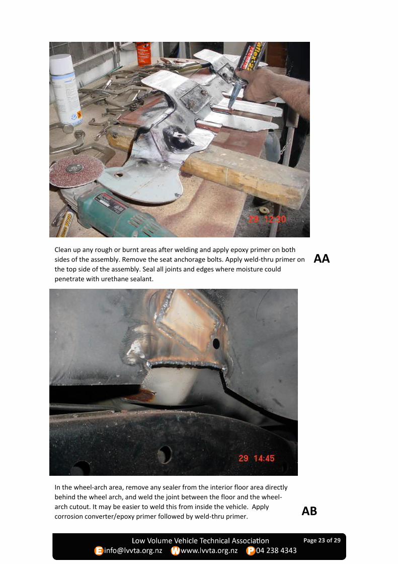
Clean up any rough or burnt areas after welding and apply epoxy primer on both
sides of the assembly. Remove the seat anchorage bolts. Apply weld-thru primer on
the top side of the assembly. Seal all joints and edges where moisture could
penetrate with urethane sealant.
AA
AB
In the wheel-arch area, remove any sealer from the interior floor area directly
behind the wheel arch, and weld the joint between the floor and the wheel-
arch cutout. It may be easier to weld this from inside the vehicle. Apply
corrosion converter/epoxy primer followed by weld-thru primer.
Page 24 of 29
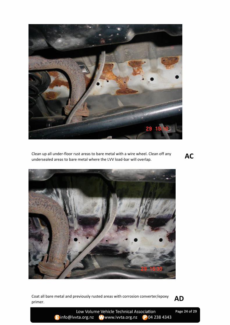
Clean up all under-floor rust areas to bare metal with a wire wheel. Clean off any
undersealed areas to bare metal where the LVV load-bar will overlap. AC
Coat all bare metal and previously rusted areas with corrosion converter/epoxy
primer. AD

Page 25 of 29
When epoxy primer is dry, apply a coating of weld-thru primer.
Slide in the load-bar/reinforcing plate assembly, jam in place with wood blocks and
fit the seat anchorage bolts to pull into location. From inside the vehicle, weld the
three plug-welds across the wheel-arch, to stop the plate bending down.
AF
AE

Page 26 of 29
In the wheel-arch area, bend up the “ears” on the load-bar by hand, then by using a
piece of wood. Apply weld-thru primer. Check the bolt hole is properly aligned. AG
Locate the seatbelt anchorage plate centrally, fit and tighten the bolt. AH
Page 27 of 29
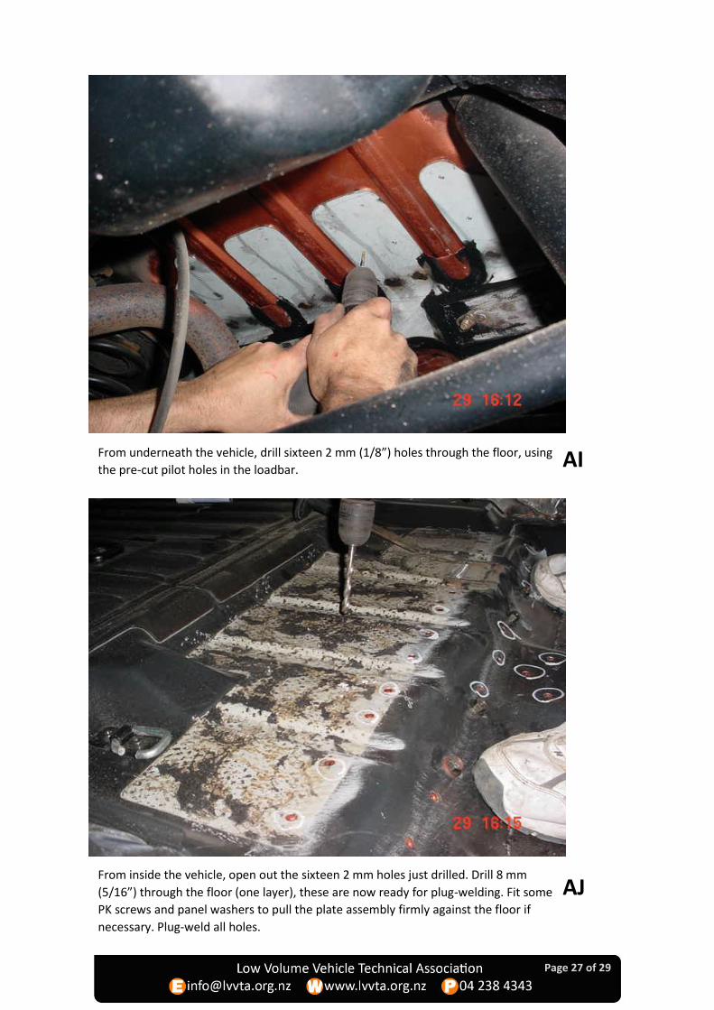
From underneath the vehicle, drill sixteen 2 mm (1/8”) holes through the floor, using
the pre-cut pilot holes in the loadbar. AI
From inside the vehicle, open out the sixteen 2 mm holes just drilled. Drill 8 mm
(5/16”) through the floor (one layer), these are now ready for plug-welding. Fit some
PK screws and panel washers to pull the plate assembly firmly against the floor if
necessary. Plug-weld all holes.
AJ
Page 28 of 29
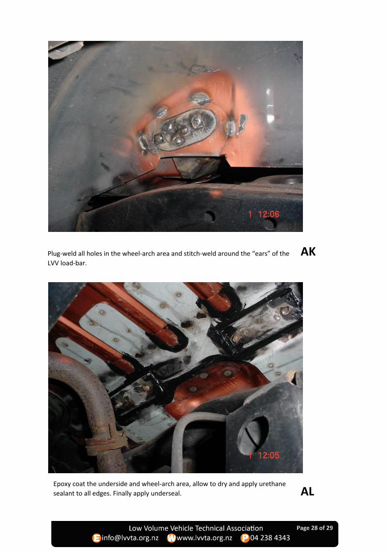
Plug-weld all holes in the wheel-arch area and stitch-weld around the “ears” of the
LVV load-bar.
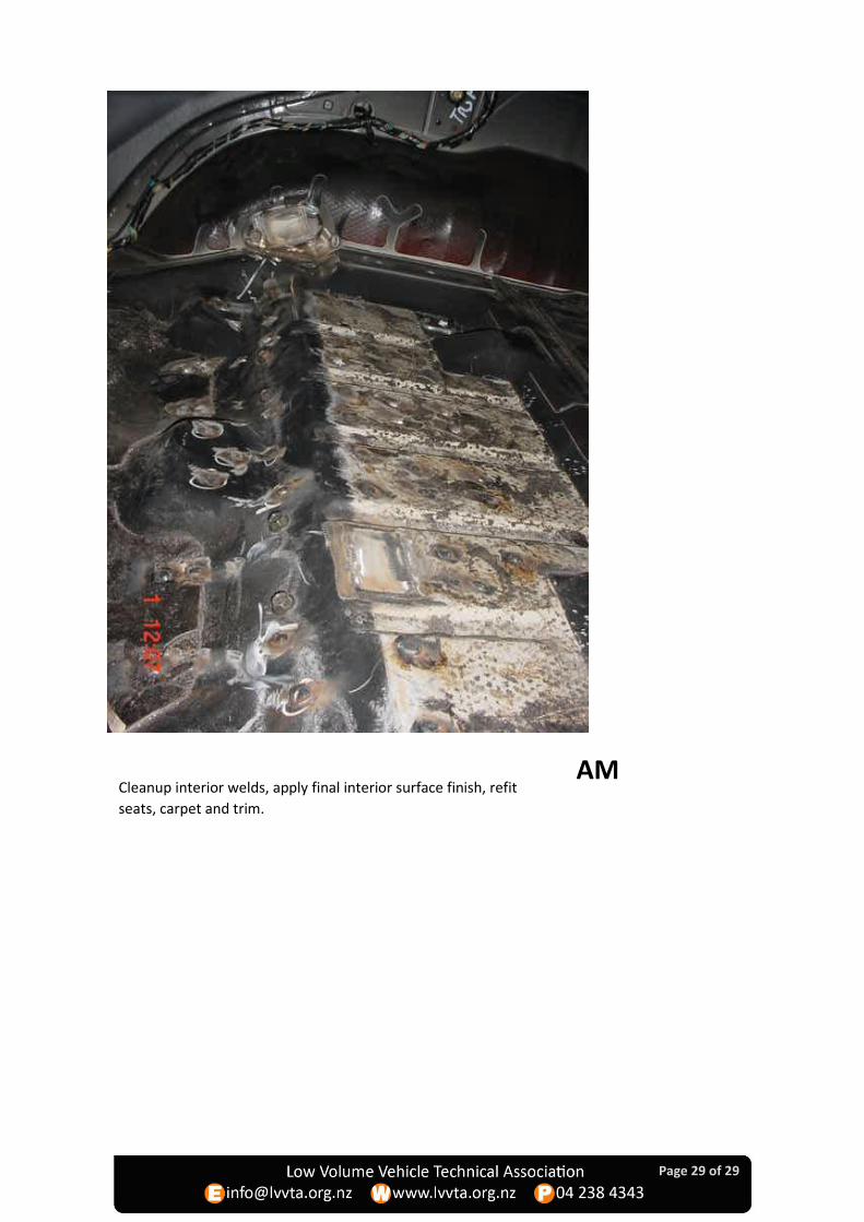
Epoxy coat the underside and wheel-arch area, allow to dry and apply urethane
sealant to all edges. Finally apply underseal. AL
AK
Page 29 of 29
Cleanup interior welds, apply final interior surface finish, refit
seats, carpet and trim.
AM