
Information Product Maintenance - Zampini Industrial · Product Maintenance Information FORCE 5i...
16
Product Maintenance Information FORCE 5i Air Winch Models FA2.5i, FA5i, and FA5Ti (Dwg. MHP2669) Save These Instructions R Form MHD56288 Edition 3 October 2013 71444277 © 2013 Ingersoll-Rand
Transcript of Information Product Maintenance - Zampini Industrial · Product Maintenance Information FORCE 5i...
Product MaintenanceInformation
FORCE 5i Air WinchModels
FA2.5i, FA5i, and FA5Ti
(Dwg. MHP2669)
Save These Instructions
R
Form MHD56288Edition 3October 201371444277© 2013 Ingersoll-Rand
Only allow Ingersoll Rand trained technicians to perform maintenance on this product. For additional information contact Ingersoll Rand factory or nearestDistributor.For additional supporting documentation refer to Table 1 ‘Product Information Manuals’ on page 2.Manuals can be downloaded from http://www.ingersollrandproducts.com.The use of other than genuine Ingersoll Rand replacement parts may result in safety hazards, decreased performance and increased maintenance and will invalidate allwarranties.Original instructions are in English. Other languages are a translation of the original instructions.Refer all communications to the nearest Ingersoll Rand Office or Distributor.
Table 1: Product Information Manuals
Publication Part/Document Number Publication Part/DocumentNumber
Product Safety Manual (Non-Man Rider) MHD56250 Product Information Manual (Man Rider) MHD56300
Product Safety Manual (Man Rider) MHD56251 Product Parts Information Manual MHD56287
Product Information Manual (Non-Man Rider) MHD56278
INSPECTIONFrequent inspections should be performed on equipment in regular service. Referto Product Information Manual. Some options may not apply to your product, referto data (name) plate for correct model and any applicable manuals.
n Periodic InspectionRefer to Table 2 ‘Inspection Classifications’ on page 3 for suggested winchinspection classifications for Periodic Inspection intervals. Select conditions mostappropriate to application.Maintain written records of periodic inspections to provide an accumulative basisfor continuing evaluation. Inspect all items listed in the ‘Frequent Inspection’ sectionof the Product Information Manual. Also inspect the following at the suggestedintervals recommended in Table 3 ‘Maintenance Interval Chart’ on page 4:
1. Siderails and Uprights. Check for deformed, cracked or corroded maincomponents. Replace damaged parts.
2. Fasteners. Check retainer rings, capscrews, nuts and other fasteners on winch,including mounting bolts. Replace if missing or damaged and tighten if loose.
3. Drum and Sheaves. Check for cracks, wear or damage. Replace if necessary.4. Wire Rope. In addition to ‘Frequent Inspection’ requirements, also inspect for
the following:a. Build-up of dirt and corrosion. Clean with steam or a stiff wire brush to
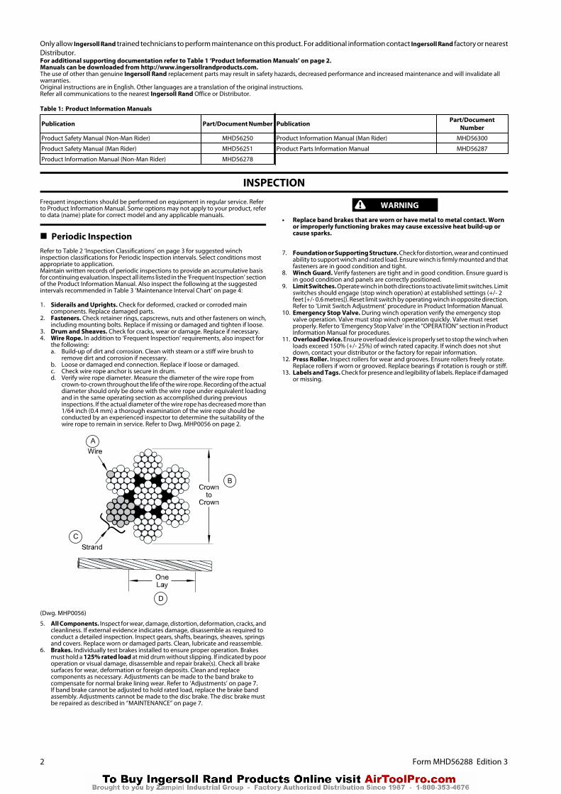
remove dirt and corrosion if necessary.b. Loose or damaged end connection. Replace if loose or damaged.c. Check wire rope anchor is secure in drum.d. Verify wire rope diameter. Measure the diameter of the wire rope from
crown-to-crown throughout the life of the wire rope. Recording of the actualdiameter should only be done with the wire rope under equivalent loadingand in the same operating section as accomplished during previousinspections. If the actual diameter of the wire rope has decreased more than1/64 inch (0.4 mm) a thorough examination of the wire rope should beconducted by an experienced inspector to determine the suitability of thewire rope to remain in service. Refer to Dwg. MHP0056 on page 2.
A
B
C
D
(Dwg. MHP0056)
5. All Components. Inspect for wear, damage, distortion, deformation, cracks, andcleanliness. If external evidence indicates damage, disassemble as required toconduct a detailed inspection. Inspect gears, shafts, bearings, sheaves, springsand covers. Replace worn or damaged parts. Clean, lubricate and reassemble.
6. Brakes. Individually test brakes installed to ensure proper operation. Brakesmust hold a 125% rated load at mid drum without slipping. If indicated by pooroperation or visual damage, disassemble and repair brake(s). Check all brakesurfaces for wear, deformation or foreign deposits. Clean and replacecomponents as necessary. Adjustments can be made to the band brake tocompensate for normal brake lining wear. Refer to ‘Adjustments’ on page 7.If band brake cannot be adjusted to hold rated load, replace the brake bandassembly. Adjustments cannot be made to the disc brake. The disc brake mustbe repaired as described in “MAINTENANCE” on page 7.
WARNING
• Replace band brakes that are worn or have metal to metal contact. Wornor improperly functioning brakes may cause excessive heat build-up orcause sparks.
7. Foundation or Supporting Structure. Check for distortion, wear and continuedability to support winch and rated load. Ensure winch is firmly mounted and thatfasteners are in good condition and tight.
8. Winch Guard. Verify fasteners are tight and in good condition. Ensure guard isin good condition and panels are correctly positioned.
9. Limit Switches. Operate winch in both directions to activate limit switches. Limitswitches should engage (stop winch operation) at established settings (+/- 2feet [+/- 0.6 metres]). Reset limit switch by operating winch in opposite direction.Refer to ‘Limit Switch Adjustment’ procedure in Product Information Manual.
10. Emergency Stop Valve. During winch operation verify the emergency stopvalve operation. Valve must stop winch operation quickly. Valve must resetproperly. Refer to ‘Emergency Stop Valve’ in the “OPERATION” section in ProductInformation Manual for procedures.
11. Overload Device. Ensure overload device is properly set to stop the winch whenloads exceed 150% (+/- 25%) of winch rated capacity. If winch does not shutdown, contact your distributor or the factory for repair information.
12. Press Roller. Inspect rollers for wear and grooves. Ensure rollers freely rotate.Replace rollers if worn or grooved. Replace bearings if rotation is rough or stiff.
13. Labels and Tags. Check for presence and legibility of labels. Replace if damagedor missing.
2 Form MHD56288 Edition 3

Table 2: Inspection Classifications
Conditions Normal Heavy Severe
Typical Use (operating time) Infrequent Regular Continual/Constant
Load Range 60% of Capacity 75% of Times Used 80% of Capacity 75% of Times Used 100% of Capacity 75% of Times Used
Installation Protected/Enclosed/Dry Not Sheltered/Exterior Full Exposure
Atmosphere Clean/Non-Corrosive Dirty/Non-Corrosive/Freshwater Marine Dirty/Corrosive/Saltwater Marine
Climate Dry/Stable Temperature Wet/Moderate Temperature Fluctuations Wet/Severe Temperature Fluctuations
n Records and ReportsInspection records, listing all points requiring periodic inspection should bemaintained for all load bearing equipment. Written reports, based on severity ofservice, should be made on the condition of critical parts as a method ofdocumenting periodic inspections. These reports should be dated, signed by theperson who performed the inspection, and kept on file where they are readilyavailable for review.
n Maintenance IntervalsRefer to Table 3 ‘Maintenance Interval Chart’ on page 4for recommendedmaintenance schedule.
Form MHD56288 Edition 3 3
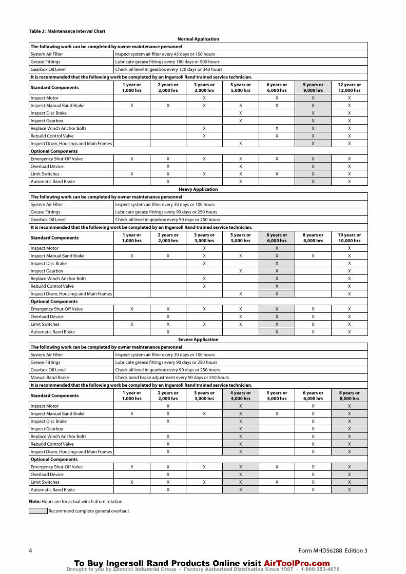
Table 3: Maintenance Interval Chart
Normal Application
The following work can be completed by owner maintenance personnel
System Air Filter Inspect system air filter every 45 days or 150 hours
Grease Fittings Lubricate grease fittings every 180 days or 500 hours
Gearbox Oil Level Check oil level in gearbox every 120 days or 340 hours
It is recommended that the following work be completed by an Ingersoll Rand trained service technician.
Standard Components 1 year or1,000 hrs
2 years or2,000 hrs
3 years or3,000 hrs
5 years or5,000 hrs
6 years or6,000 hrs
9 years or9,000 hrs
12 years or12,000 hrs
Inspect Motor X X X X
Inspect Manual Band Brake X X X X X X X
Inspect Disc Brake X X X
Inspect Gearbox X X X
Replace Winch Anchor Bolts X X X X
Rebuild Control Valve X X X X
Inspect Drum, Housings and Main Frames X X X
Optional Components
Emergency Shut-Off Valve X X X X X X X
Overload Device X X X X
Limit Switches X X X X X X X
Automatic Band Brake X X X X
Heavy Application
The following work can be completed by owner maintenance personnel
System Air Filter Inspect system air filter every 30 days or 100 hours
Grease Fittings Lubricate grease fittings every 90 days or 250 hours
Gearbox Oil Level Check oil level in gearbox every 90 days or 250 hours
It is recommended that the following work be completed by an Ingersoll Rand trained service technician.
Standard Components 1 year or1,000 hrs
2 years or2,000 hrs
3 years or3,000 hrs
5 years or5,000 hrs
6 years or6,000 hrs
8 years or8,000 hrs
10 years or10,000 hrs
Inspect Motor X X X
Inspect Manual Band Brake X X X X X X X
Inspect Disc Brake X X X
Inspect Gearbox X X X
Replace Winch Anchor Bolts X X X
Rebuild Control Valve X X X
Inspect Drum, Housings and Main Frames X X X
Optional Components
Emergency Shut-Off Valve X X X X X X X
Overload Device X X X X X
Limit Switches X X X X X X X
Automatic Band Brake X X X X
Severe Application
The following work can be completed by owner maintenance personnel
System Air Filter Inspect system air filter every 30 days or 100 hours
Grease Fittings Lubricate grease fittings every 90 days or 250 hours
Gearbox Oil Level Check oil level in gearbox every 90 days or 250 hours
Manual Band Brake Check band brake adjustment every 90 days or 250 hours
It is recommended that the following work be completed by an Ingersoll Rand trained service technician.
Standard Components 1 year or1,000 hrs
2 years or2,000 hrs
3 years or3,000 hrs
4 years or4,000 hrs
5 years or5,000 hrs
6 years or6,000 hrs
8 years or8,000 hrs
Inspect Motor X X X X
Inspect Manual Band Brake X X X X X X X
Inspect Disc Brake X X X X
Inspect Gearbox X X X
Replace Winch Anchor Bolts X X X X
Rebuild Control Valve X X X X
Inspect Drum, Housings and Main Frames X X X X
Optional Components
Emergency Shut-Off Valve X X X X X X X
Overload Device X X X X
Limit Switches X X X X X X X
Automatic Band Brake X X X X
Note: Hours are for actual winch drum rotation.
Recommend complete general overhaul.
4 Form MHD56288 Edition 3
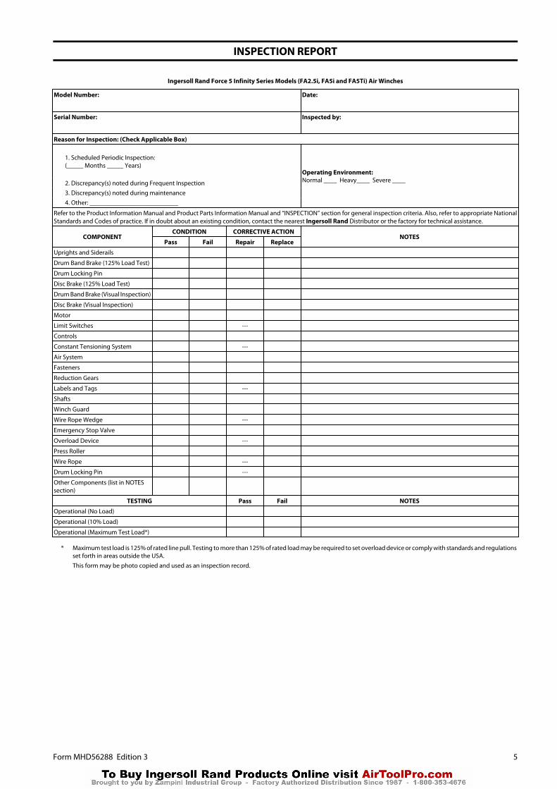
INSPECTION REPORT
Ingersoll Rand Force 5 Infinity Series Models (FA2.5i, FA5i and FA5Ti) Air Winches
Model Number: Date:
Serial Number: Inspected by:
Reason for Inspection: (Check Applicable Box)
1. Scheduled Periodic Inspection:(_____ Months _____ Years)
Operating Environment:Normal ____ Heavy____ Severe ____2. Discrepancy(s) noted during Frequent Inspection
3. Discrepancy(s) noted during maintenance4. Other: ___________________________
Refer to the Product Information Manual and Product Parts Information Manual and “INSPECTION” section for general inspection criteria. Also, refer to appropriate NationalStandards and Codes of practice. If in doubt about an existing condition, contact the nearest Ingersoll Rand Distributor or the factory for technical assistance.
COMPONENTCONDITION CORRECTIVE ACTION
NOTESPass Fail Repair Replace
Uprights and Siderails
Drum Band Brake (125% Load Test)
Drum Locking Pin
Disc Brake (125% Load Test)
Drum Band Brake (Visual Inspection)
Disc Brake (Visual Inspection)
Motor
Limit Switches ---
Controls
Constant Tensioning System ---
Air System
Fasteners
Reduction Gears
Labels and Tags ---
Shafts
Winch Guard
Wire Rope Wedge ---
Emergency Stop Valve
Overload Device ---
Press Roller
Wire Rope ---
Drum Locking Pin ---
Other Components (list in NOTESsection)
TESTING Pass Fail NOTES
Operational (No Load)
Operational (10% Load)
Operational (Maximum Test Load*)
* Maximum test load is 125% of rated line pull. Testing to more than 125% of rated load may be required to set overload device or comply with standards and regulationsset forth in areas outside the USA.
This form may be photo copied and used as an inspection record.
Form MHD56288 Edition 3 5

TROUBLESHOOTINGThis section provides basic troubleshooting information. Determination of specific causes to problems are best identified by thorough inspections performed by personnelinstructed in safety, operation and maintenance of this equipment. The chart below provides a brief guide to common winch symptoms, probable causes and remedies.
SYMPTOM CAUSE REMEDYWinch will not operate. Insufficient or no air supply to winch. Check air supply line connections and hoses.
Winch is overloaded. Reduce load to within rated capacity.Disc brake does not release. Pressurize disc brake release port and check for leakage. Replace brake piston seals
if leakage is found. Ensure air pressure at inlet to disc brake is at least 45 psig (3.1bar/310 kPa). Inspect brake piston seals and replace if seals appear to be leaking.
Shipping plugs may still be in place. Remove shipping plugs in valve and motor exhaust ports.
Drum brake does not release. Disengage manual band brake, or refer to on page 7.
Emergency stop valve engaged. Reset emergency stop valve.
Motor may be damaged. Disassemble and clean the motor and replace any broken or damaged parts.Air leak. Check hose and fitting connections. Inspect hose(s) for breaks. Tighten fittings and
repair or replace hoses as necessary.Overload device engaged. Reduce load to within rated capacity of winch. If overload device cannot be reset,
contact factory.Air lines freeze due to water in air supply. Install or drain air system moisture traps, moisture collecting air receivers and
compressor aftercoolers. After corrective action has been taken, disconnect lines atwinch inlet and purge with clean, dry air or nitrogen.
Load continues to move when winch isstopped.
Brake is slipping. Check brake band lining wear. Check brake friction disc wear. Refer to “Adjustments”on page 7.
Winch is overloaded. Reduce load to within rated capacity.Winch motor controls sticking. Check pendant/throttle levers spring return to normal (neutral) position when
released.Winch does not lift load or does not liftrated capacity. Winch does not lift/pullload.
Motor may be damaged. Remove and disassemble motor as described in “MAINTENANCE” on page 7.Examine all parts and replace any that are worn or damaged.
Insufficient air supply. Verify air supply pressure and volume at winch inlet meets the requirements listedin the “SPECIFICATIONS” section in Product Information Manual. Clean air line filter.
Brake is not releasing. Check brake release pilot hole is not restricted. Check seals on cylinder piston arenot damaged. Brake will start to release at 45 psig (3.1 bar/310 kPa).
Winch is overloaded. Reduce load to within rated capacity.Oil leak from motor end of winch. Reduction assembly is leaking. Disassemble winch and inspect reduction assembly seals.Throttle or pendant lever moves but winchdoes not operate.
Motor may be damaged. Disassemble and clean motor and replace any broken or damaged parts.Insufficient air supply. Ensure air pressure at winch inlet is at least 90 psig (6.3 bar/630 kPa) at rated volume.
Clean air line filter.Air leak. Check hose and fitting connections. Inspect hose(s) for breaks. Tighten fittings and
repair or replace hoses as necessary.Motor does not run smoothly or makesexcessive noise during operation.
Damaged or broken piston or connectingrod.
Disassemble and repair motor.
Motor runs hot or makes excessive noiseduring operation.
Low oil level. Check oil level in motor. Add oil as required to obtain proper level.Improper lubrication. Replace oil with type recommended in “LUBRICATION” section in Product
Information Manual. Set lubricator to provide 6 to 9 drops of oil per minute atmaximum winch operating capacity.
Water in oil. Drain and refill with recommended oil. Operate winch with no load slowly, in bothdirections. If noise still exists or motor overheats disassemble and repair motor.
Damaged or broken piston or connectingrod. Disassemble and repair motor.
Winch runs slow. Improper hose or fitting sizes. Check fittings, connections and hoses for correct size and length. Replace parts thatmay cause restricted air flow. Inspect air line filter.
Motor may be damaged. Remove and disassemble motor as described in “MAINTENANCE” on page 7.Inspect all parts and replace all worn or damaged parts.
Brake(s) not releasing. Refer to brakes in “MAINTENANCE” on page 7.Insufficient air supply. Verify air supply pressure and volume at winch inlet meets the requirements. Refer
to “SPECIFICATIONS” section in Product Information Manual. Clean air line filter.Air lines freeze. Water in air supply. Install or drain air system moisture traps, moisture collecting air receivers and
compressor aftercoolers. After corrective action has been taken, disconnect lines atwinch inlet and purge with clean, dry air or nitrogen.
Throttle lever hard to actuate, or lever doesnot spring return to neutral.
Reverse valve sticking in bushing. Remove and disassemble control valve. Clean control valve parts and checkclearance between reverse valve and bushing.
Automatic Band Brake:Brake cylinder will not release. Band brake out of adjustment. Adjust band brake to maintain correct cylinder stroke.
Leaking cylinder seals. If air is noticed escaping from cylinder breather when attempting to release brake,replace or repair cylinder.
Dirty filter in air supply. Clean or replace filter.Faulty dump valve. Check dump valve exhaust port. Air should exhaust when control valve handle is in
neutral. If no air escapes, replace dump valve.Automatic Disc Brake:Brake fails to release. Low air supply pressure. Ensure air pressure at inlet to disc brake is at least 45 psig (3.1 bar/310 kPa).
Leaking piston seals. Inspect brake breather. If air escapes from brake breather when attempting torelease brake, replace brake seals.
No release pressure at brake port. Check for proper operation of winch controls.Sticking brake piston. Apply 45 psig (3.1 bar/310 kPa) to brake release port and check for brake disc
movement. (Brake discs can be viewed through brake breather hole.) If brake discsdo not move, disassemble and inspect disc brake as described in“MAINTENANCE” on page 7.
6 Form MHD56288 Edition 3

MAINTENANCE
WARNING
• Never perform maintenance on the winch while it is supporting a load.• Before performing maintenance, tag controls:
WARNING - DO NOT OPERATE, EQUIPMENT BEING REPAIRED.
• Only allow Ingersoll Rand trained Technicians to perform maintenance onthis winch.
• Shut off air system and depressurize air lines before performing anymaintenance.
• Do not use Trichloroethylene to clean parts.• Use of other than genuine Ingersoll Rand parts may result in safety hazards,
decreased performance and increased maintenance and will invalidate allwarranties.
• After performing any maintenance on the winch, test winch to 125% of itsrated line pull at mid drum before returning to service. (Testing to morethan 125% of rated line pull may be required to comply with standards andregulations set forth in areas outside the USA.)
NOTICE
• Some options are not available for a Man Rider winch, refer to data (name)plate.
n GeneralCorrect disassembly (to prevent loss or damage of good parts), repair, assembly,testing and adjusting are critical to proper winch operation. Maintenanceprocedures are technical in nature and require training and experience toaccomplish correctly. In addition, repair and testing require specialized equipmentthat is not typically found at the products mounting site.
Proper use, inspections and maintenance increase the life and usefulness of yourIngersoll Rand equipment. During assembly, lubricate gears, nuts, capscrews andall machined threads with applicable lubricants. Use of anti-seize compound and/or thread lubricant on capscrew and nut threaded areas prevents corrosion andallows for easy disassembly of components.
It is extremely important that anyone involved with maintaining the product befamiliar with the servicing procedures of these products and be physically capableof conducting the procedures. These personnel shall have skills that include:
1. Proper and safe use and application of mechanics’ common hand tools as wellas special Ingersoll Rand or recommended tools.
2. Safety procedures, precautions and work habits established by acceptedindustry standards.
Ingersoll Rand cannot know of or provide all the procedures by which productoperations or repairs may be conducted and the hazards and/or results of eachmethod. If operation or maintenance procedures not specifically recommended bythe manufacturer are conducted, it must be ensured that product safety is notendangered by the actions taken. If unsure of an operation or maintenanceprocedure or step, personnel should place the product in a safe condition andcontact supervisors and/or the factory for technical assistance.
NOTICE
• Refer to the Product Parts Information Manual for drawings unlessspecified elsewhere.
n Maintenance IntervalsRefer to Table 3 ‘Maintenance Interval Chart’ on page 4 for recommendedmaintenance schedule.
n Adjustments
n Guarding
Refer to Dwg. MHP2676.Drum guard panels must be adjusted to suit wire rope departure angle. Adjust perprocedures in Product Information Manual.
n Disc Brake
Refer to Dwg. MHP2674.Disc brake adjustment is not required. If disc brake does not hold rated load,disassemble and repair.If brake assembly is removed or disassembled, ensure breather (29) is installed andlocated at top of brake housing during reassembly.
n Manual and Automatic Band Brake
Refer to Dwg. MHP2694.
Manual Band Brake:1. Release wire rope tension on drum.2. Raise handle (104) to free brake bands (128).3. Remove cotter pin (102) and pin (101).
4. Rotate link stud (103) clockwise to increase brake torque.5. Install pin (101) and check adjustment.6. Brake should be adjusted until brake lever over center position can be attained
with 50 to 100 lb. (23 to 45 kg) force on handle (104).7. Install cotter pin (102) when adjustment is completed. Bend ends of cotter pin
over.
CAUTION
• When any part of brake lining measures 0.062 in. (2 mm) or less, bands brakemust be replaced.
Automatic Band Brake:1. Remove cotter pin (102) at adjustment clevis (107).2. Apply air to brake cylinder (110) and remove pin (106) to disconnect clevis from
brake lever (105).3. Turn adjustment clevis (107) clockwise to increase cylinder rod extension. Turn
clevis counterclockwise to decrease cylinder rod extension.4. Assemble clevis (107) to brake lever (105) with pin (106). Release air to brake
cylinder (110).5. Measure cylinder rod extension. Length should be 1 to 1-1/2 in. (25 to 37 mm).
Readjust if necessary.6. Install cotter pin (102) to secure clevis to brake lever when adjustment is
complete. Bend ends of cotter pin over.7. With brake ‘On,’ adjust screw (127) to just touch arm (124).
n Pendant Operated Pilot Control Valve
Valve is set at factory. Refer to “Pendant Operated Pilot Control ValveAssembly”on page 12 for adjustment procedure.
n Overload Valve
Refer to Dwg. MHP2619 in Product Information Manual. A. Emergency Stop Button;B. Push Down to Stop Winch Movement; C. Overload Valve Reset Button; D. TwistRed Button to Reset; E. Overload Valve Adjustment Screw.
A 5/16 inch or 8 mm open-ended wrench is required.
Adjust overload valve by turning adjustment screw located at bottom of controlvalve.
- Rotating adjustment screw (clockwise) will increase pressure required toactivate overload valve.
WARNING
• This adjustment can cause overload device to NOT activate before winch'ssafety limit is exceeded. This procedure should only be done by IngersollRand trained Technicians.
- Rotating adjustment screw (counterclockwise) will decrease pressurerequired to activate overload valve.
n Limit Switch
Refer to ‘Limit Switch Adjustment’ procedure in Product Information Manual.
n Tensioning System
Refer to Dwg. MHP2028.The regulator is preset at 0 psig (0 bar/0 kPa) and therefore requires adjustmentwhen winch is installed. To adjust for specific load applications, regulator pressuremay be adjusted to increase or decrease tension setting.Regulator gauge and regulator are accessible through cover.
WARNING
• When adjusting regulator, ensure winch control lever is locked in neutralposition and tension selector lever is in the NORMAL position.
• Winch supply air is NOT shut off during regulator adjustments. To preventaccidental winch operation, allow only a single person, trained inoperation, safety and maintenance of this product, to conduct regulatoradjustments.
Regulator Adjustment Procedure:Refer to Dwg. MHP1865 in Product Information Manual.
1. Attach test load of desired weight to load line, or connect load line to scale.
WARNING
• Ensure load line is connected to load and excessive slack is taken up beforeactivating auxiliary valve. When activated, auxiliary valve willautomatically engage and winch will operate at full speed to set tension onload line.
2. Using winch control valve remove all slack from load line.
Setting with test load:Actuate auxiliary valve to TENSIONING position. Winch should operate, causing loadline to become taut. To increase tension, rotate regulator knob clockwise until loadbegins to rise. Rotate regulator knob counterclockwise a minimum of 1/4 turn, or untilload is balanced (does not raise or lower). Note pressure indicated on gauge forfuture setting reference.
Form MHD56288 Edition 3 7

Setting with scale:Actuate auxiliary valve to TENSIONING position. Winch should operate, causing loadline to become taut. To increase tension, rotate regulator knob clockwise until scaleindicates desired tension. Note pressure indicated on gauge for future settingreference.
n Disassembly
n General Disassembly Instructions
The following instructions provide necessary information to disassemble, inspect,repair, and assemble product. Parts drawings are provided in Product PartsInformation Manual.If a product is being completely disassembled for any reason, follow the order oftopics as they are presented. It is recommended that all maintenance work onproduct be performed in a clean dust-free work area.In the process of disassembling product, observe the following:
1. Never disassemble product any further than is necessary to accomplish neededrepair. A good part can be damaged during the course of disassembly.
2. Never use excessive force when removing parts. Tapping gently aroundperimeter of a cover or housing with a soft hammer, for example, is sufficient tobreak the seal.
3. Do not heat a part with a flame to free it for removal, unless part being heatedis already worn or damaged beyond repair and no additional damage will occurto other parts.
In general, products are designed to permit easy disassembly and assembly. Theuse of heat or excessive force should not be required.
4. Keep work area as clean as practical, to prevent dirt and other foreign matterfrom getting into bearings or other moving parts.
5. All seals, gaskets and ‘O’ rings should be discarded once they have beenremoved. New seals and ‘O’ rings should be used when assembling product.
6. When grasping a part in a vise, always use leather-covered or copper-coveredvise jaws to protect the surface of part and help prevent distortion. This isparticularly true of threaded members, machined surfaces and housings.
7. Do not remove any part which is a press fit in or on a subassembly unless removalof that part is necessary for repairs or replacement.
8. When removing ball bearings from shafts, it is best to use a bearing puller. Whenremoving bearings from housings, drive out bearing with a sleeve slightlysmaller than outside diameter of bearing. The end of sleeve or pipe whichcontacts bearing must be square. Protect bearings from dirt by keeping themwrapped in clean cloths.
n Winch Disassembly
Refer to Dwgs. MHP2689 or MHP2670, MHP2693 and MHP2624.1. Remove wire rope from drum.2. Operate winch to position reduction gear drain plug at its lowest position.3. Relieve pressure in air lines by operating winch control several times after air
supply has been turned off.
WARNING
• Shut off, bleed down and disconnect air supply line before performing anydisassembly procedures.
4. Tag and disconnect hoses to motor and control valve.5. Remove winch from its mounting and move to a suitable work area before
beginning disassembly.6. Remove lower case drain plug (225) on K5B motor housing (217) and allow oil
to drain into a suitable container. Loosen fill cap (210) to vent motor housing.7. Drain oil from reduction gear assembly by removing one plug (48) when
positioned at its lowest point, and one plug (48) from its highest point to vent.Refer to Dwg. MHP0140 in Product Information Manual. If winch is equippedwith a drum band brake, elevate winch outboard end (opposite from motor end)to prevent draining oil from contaminating brake band lining.
8. For winches with a disc brake, remove pipe plug (31) in brake housing (17) todrain brake oil.
9. Remove drum band brake, winch guard and any other externally mounted winchattachments.
10. Drum guard disassembly (refer to Dwgs. MHP2676 and MHP2689):a. Remove panels (805) and (807), one section at a time, by removing locknuts
(804) and crossbars (806).b. Remove capscrews (90) and washers (91) securing lifting lugs (83) to
uprights.c. Remove capscrews (809) and washers (96) securing frames (802) and (801)
to uprights (42) and (84).
WARNING
• The air motor weighs approximately 260 lb (118 kg). Adequately supportair motor before removing motor mounting capscrews.
11. Remove capscrews (4) and lockwashers (3) securing motor assembly to motoradapter (6). Using a hoist to support motor, pull motor straight away from winch.Reference the applicable ‘Motor Disassembly’ section on page 8 if motordisassembly is required.
Instructions 12 through 18 apply only to winches with a disc brake.12. Alternately and evenly loosen eight capscrews (93) until brake spring
compression is relaxed. Remove capscrews and motor adapter (6).13. Remove brake housing (17). If brake housing sticks, tap it with a soft faced
hammer until parts separate.14. Note position of all brake parts for reassembly.15. Remove five friction plates (19) and six drive plates (18).16. Remove springs (9) from brake piston (10).17. Remove brake piston (10) from brake housing (17). Tap lightly with a plastic
mallet to separate parts, if necessary.18. Remove seals (11) and (12) from brake piston (10).
19. Loosen capscrew in collar (13) and slide collar from shaft (7) with gear (21) fromdrive shaft (35).
20. Remove retainer ring (36) from bore of drum shaft (41).21. Pull shaft and bearing assembly from drum shaft (41).22. Support drum (80) and remove capscrews (39) from drum shaft (41). Pry drum
shaft (41) from inboard upright (42).23. Remove capscrews (85) and lockwashers (98) that secure siderails (82) to inboard
upright (42). Drive out dowel pins (86).24. Remove inboard upright (42).25. Remove capscrews (97), lockwashers (96) and end cover (95) from outboard
upright (84).26. Remove capscrews (94) and bearing retainer (92) from drum (80).27. Remove drum and reduction gear assembly.28. Remove remaining capscrews (85) and lockwashers (86) that attach siderails (82)
to outboard upright (84). Drive out dowel pins (86).29. Remove bearing (87) from outboard upright (84).30. Remove capscrews (45) and lockwashers (46) securing gear carrier (47) to drum
(80).31. Install two 3/4 in. - 10 NC x 3 in. long capscrews into threaded holes in outer bolt
pattern ring of gear carrier (47). Use these capscrews to break seal. Removereduction gear assembly from drum (80).
32. Remove dowel pins (40) or (86) from gear carrier (47).
To disassemble reduction gear refer to ‘Reduction Gear Disassembly’ on page 8.
n Manual or Automatic Band Brake Disassembly
Refer to Dwg. MHP2694.1. Automatic Brake:
a. Disconnect and remove hose, fittings and dump valve (112) from cylinder(110).
b. Remove cotter pin (102) and pin (101) from link stud (103) and band brake(128).
c. Remove cotter pin (102) and pin (106). Separate clevis (107) from brake lever(105).
d. Remove cotter pin (102) and pin (134). Remove cylinder (110) from bracket(118).
2. Manual Brake:a. Remove cotter pin (102) and pin (101) from handle (104) then remove handle
(104) from band brake (128).3. Remove capscrews (119), lockwashers (117) and stop plate (126).4. Use a hoist to raise winch approximately 6 inches (15 cm). Separate band brake
(128) halves and rotate band brake assembly slowly until it can be removed fromdrum (80).
5. Remove cotter pins (102) and pins (121) so brake band halves (128) can beremoved from arm (124). Lower winch when band brake assembly has beenremoved.
n Reduction Gear Disassembly
NOTICE
• It is important to maintain a clean work area when reduction gear assemblyis disassembled.
• Disassembly is not recommended. If it is unavoidable, use the followingsteps.
Model FA2.5i:Refer to Dwg. MHP2689.1. Place reduction gear assembly on a clean work bench so that end containing
bearing (49) is down.2. Remove capscrews (75) and pry off cover (73).3. Remove ring gear (72), planetary assembly (67) and sun gear (69).4. Remove and discard ‘O’ rings (62) from ring gear (72).5. Remove four dowel pins (74) from between cover (73) and spacer (71) and store
in a safe place.6. Remove spacer (71), ring gear (63) and sun gear (66).7. If required, remove thrust bearing (55) from sun gear (66).8. Remove planetary assembly (54).9. Remove ring gear (63). Remove four dowel pins (70) from ring gear and store in
a safe place.10. Remove and discard ‘O’ rings (62) from ring gear (63).11. Remove retainer ring (50) and bearing (49) from gear carrier (47).
Models FA5i and FA5Ti:Refer to Dwg. MHP2670.1. Remove plug (48) from gear carrier (47). Rotate reduction gear to drain oil from
level plug hole.2. Place reduction gear assembly on a clean work bench so that end containing
bearing (49) is down.3. Remove capscrews (75) and pry off cover (73).4. Remove ring gear (72), planetary assembly (67) and sun gear (69).5. Remove and discard ‘O’ rings (62) from ring gear (72).6. Remove four dowel pins (74) from between cover (73) and spacer (71) and store
in a safe place.7. Remove spacer (71), ring gear (63) and sun gear (66).8. If required, remove thrust bearing (55) from sun gear (66). Remove and discard
‘O’ rings (62) from ring gear (63).9. Remove capscrews (60) from input housing (59). Separate input housing from
gear carrier (47).10. Remove planetary assembly (58).11. Remove ring gear (53). Remove three dowel pins (52) from between input
housing (59) and gear carrier (47) and store in a safe place.12. Remove and discard ‘O’ rings (51) from ring gear (53).13. Remove retainer ring (57) and sun gear (56). If required, remove thrust bearing
(55) from sun gear.14. Remove planetary assembly (54).15. Remove retainer ring (50) and bearing (49) from gear carrier (47).
8 Form MHD56288 Edition 3

NOTICE
• Do not disassemble planetary gear assemblies (54), (58) and (67).
n Motor Disassembly
Refer to Dwgs. MHP2693 and MHP2696.1. Remove pipe plugs (225) to drain oil from motor.2. Remove four capscrews (951) and washers (949) that secure control valve (900)
to rotary valve housing (247).3. Remove control valve assembly and gaskets (946).4. Remove five capscrews (93) from exhaust flange (253).5. Remove rotary valve housing (247) by pulling it out of motor housing (217) as
an assembly with exhaust flange (253).
CAUTION
• Do not remove the exhaust flange (253) until rotary valve (250) has beenremoved from rotary valve housing (247).
6. Remove rotary valve (250) by pulling it out from assembly through the motorhousing end of rotary valve housing (247).
7. Support motor assembly and remove ten capscrews (4) and lockwashers (3). Pullmotor assembly away from winch.
8. Remove each cylinder head (201) by removing four capscrews (200). Removehead gasket (209).
9. Pull cylinder liner (208) straight out.10. Position piston (204) at top of its stroke. In this position, with cylinder liner pulled
out, wrist pin (203) can be removed. Remove one retainer ring (205) on wrist pin(203) from either side of piston (204). Push wrist pin (203) out by hand from oneside. If wrist pin is too tight, it is acceptable to carefully heat piston to 200°F (93°C)or less and then push wrist pin out.
NOTICE
• If piston, wrist pin, connecting rod or cylinder liner are to be reassembled,number each set. Also add radial alignment marks for each piston andcylinder liner to motor housing.
11. Remove remaining cylinder liners and pistons as described above. To removecrank assembly, all pistons and cylinder liners must be removed.
12. Crank assembly (231) can now be removed with oil slinger (230) by pullingstraight out from motor housing (217). Use care while guiding connecting rods(206) through inside of motor housing.
Crankshaft Disassembly:1. Remove bearing (228) and roll pin (240) from crank assembly (231).2. Remove cotter pin (236) and pin nut (237) from lock pin (235).3. Remove lock pin (235) by carefully driving it out of its location. Use care not to
damage pin threads.4. Pull crankshaft valve end off crank assembly (231).5. Remove connecting rod rings (234), connecting rod bushing (233), sleeve (232)
and connecting rods (206). Record five connecting rod (206) numbers and footdirections so they can be reinstalled in same order.
6. Oil slinger (230) does not have to be removed unless damaged. If removal isrequired, heating of five buttonhead screws (229) may be necessary to loosenLoctite® connection.
n Control Valve Disassembly
Refer to Dwg. MHP2696.
Handle Removal:Handle disassembly is not recommended.1. Carefully pry off plug (935).2. Remove capscrew (901) and tablock washer (909).
NOTICE
• Observe spring (937) connection during disassembly. This spring is undertension and is required to return handle to neutral position.
3. Carefully pull handle assembly (930) from reverse valve (943). Remove spring(937).
Reverse Valve Removal:1. Remove buttonhead screws (938), capscrews (925) and washers (924) from seal
bracket (939). Remove seal bracket from valve housing (917). Remove anddiscard ‘O’ rings (941) and (942).
2. Remove capscrews (901) and washers (902) from exhaust flange (955). Removeflange from valve housing. Remove and discard ‘O’ ring (942).
3. Slide reverse valve (943) out exhaust flange side of housing until ball (916) isvisible on reverse valve. Allow ball (916) to drop out of bushing (944) and removeball.
4. Remove bushing (944) from exhaust flange side of housing.
NOTICE
• Dowel pin (945) allows the bushing (944) to be removed only from theexhaust flange side of housing. Ball (916) retains reverse valve (943) inbushing.
• Do not remove reverse valve (943), bushing (944), and ball (916) at the sametime; damage may occur to bushing.
• Take care to not allow ball (916) to drop into motor. If this occurs it may benecessary to disassemble motor to retrieve ball.
Piston Removal:1. Remove capscrews (901) and washers (902) from piston cover (919). Remove
cover and discard gasket (918).2. Remove capscrews (901) and washers (902) from poppet cover (903). Remove
cover and discard gasket (904).
3. Remove the following items from housing poppet bore: poppet spring (905),poppet cap (906) and poppet seal (907).
4. From poppet side, push piston (922) out of valve housing (917). Remove ‘O’ rings(921) and (923) and discard.
Pilot Valve Removal:
NOTICE
• For easier removal, it is recommended to use Ingersoll Rand pilot valve tool(920). This must be purchased separately.
If pilot valve is not damaged, it is not necessary to disassemble completely.1. Remove plug (912).2. Remove pilot valve assembly (910) as an assembly.3. Discard and replace pilot valve assembly (910) if necessary.
n Emergency Stop and Overload Control Valve Disassembly
Refer to Dwg. MHP2697.
Handle Removal:Follow disassembly instructions in ‘Control Valve Disassembly’ on page 9.
Reverse Valve Removal:1. Remove buttonhead screws (938), capscrews (925) and washers (924) from seal
bracket (939). Remove seal bracket from valve housing (917). Remove anddiscard ‘O’ rings (941) and (942).
2. Remove capscrews (721), washers (902), exhaust flange (955) and exhaustadapter (723). Remove and discard ‘O’ rings (942) and (722).
3. Move reverse valve (943) out exhaust flange side of valve housing (917) until ball(916) is visible on reverse valve. Allow ball (916) to drop out of bushing (944) andremove ball.
4. Remove bushing (944) from exhaust flange side of housing.
NOTICE
• Dowel pin (945) allows the bushing (944) to be removed only from theexhaust flange side of housing. Ball (916) retains reverse valve (943) inbushing.
• Do not remove reverse valve (943), bushing (944) and ball (916) at the sametime; damage may occur to bushing.
• Take care to not allow ball (916) to drop into motor. If this occurs it may benecessary to disassemble motor to retrieve ball.
Piston Removal:Follow disassembly instructions in ‘Control Valve Disassembly’ on page 9.
Pilot Valve Removal:Follow disassembly instructions in ‘Control Valve Disassembly’ on page 9.
Emergency Stop Removal:1. Unscrew adapter (706) and E-Stop button (705) from valve housing.2. Remove plunger (707). Remove and discard ‘O’ rings (703).3. Pull spring (711) out of valve housing (917) and discard.
Overload Valve Removal:1. Unscrew cap (700). Remove and discard grommet (701).2. Pull out plunger (702), remove and discard ‘O’ rings (703).3. Remove capscrews (901) and washers (902) from cover (719) underneath valve
housing (917).
NOTICE
• Cover (719) retains spring (718). To remove capscrews (901) and washer(902), unscrew in a crisscross pattern.
4. Remove adjusting screw (720) and ‘O’ ring (716).5. Remove adjusting nut (717), plate (715), gasket (714), ‘O’ ring (713) and piston
(712) from valve housing (917). Discard gasket (714) and ‘O’ ring (713).
n Pendant Operated Pilot Control Valve Disassembly
Refer to Dwg. MHP2969.
CAUTION
• Do not disassemble end caps of control valve. Valve caps are press fittogether and have a close fit tolerance,
1. Remove capscrews (951) and washers (96) that secure valve to motor on adapter(369). Capscrews and washers (96) cannot be removed until adapter is separatedfrom valve body (339). Separate valve as an assembly from winch motor rotaryvalve housing (247).
2. Remove capscrews (370) and separate adapter (369) from valve body. Removeand discard gasket (358).
3. Remove retainer ring (362). Pull poppet assembly (357) along with poppet seat(361) and valve piston (364) from valve body (339).
4. Reach into valve body and remove spring (356) and exhaust poppet (354).5. Remove retainer ring (365) and separate valve piston (364) and poppet seat
(361).6. Remove and discard ‘O’ rings (360), (713) and (363).7. Push shaft (331) to front of valve body to cause pin (335) to push seat restrictor
(333) out of valve body.8. Remove and discard ‘O’ ring (334). Support shaft (331) on both sides of pins (335)
and push pins out.9. Insert allen wrench into open hole in sleeve (338) and back out setscrew (337) a
couple of turns to loosen sleeve on shaft (331). Remove sleeve.10. To remove valve assemblies (341) or pins (347), remove capscrew (381), washer
(344) and spring clip (343). From the exhaust port, using a soft material probe,push valve assembly or pin up through top of valve body until it can be graspedfrom the top. Pull out valve assembly or pin.
Form MHD56288 Edition 3 9

n Press Roller Disassembly
Refer to Dwgs. MHP2695.1. Compress ends of springs (405) and (406) to disengage from side rail (82) and
pin on press roller arm (407).
CAUTION
• Use care when releasing springs (405) and (406) from press roller. Springsare under tension.
2. Loosen collars (404).
NOTICE
• Ensure press roller assembly is adequately supported before removingshaft (403).
3. Remove capscrews (408) and washers (409) from both ends of shaft (403), andcarefully slide shaft (403) through hole in upright (42). Press roller assembly (400)and collar (404) will fall away from shaft (403).
4. It is not necessary to remove bushings (410) unless replacing.5. Remove springs (405) and (406) from press roller arm (407).6. Remove capscrews (408), washers (409) and rollers (402) from ends of press roller
arm (407).
n Remote Two Lever Pendant Disassembly
Refer to Dwg. MHP2716 or MHP2717.1. Remove fittings (327) and lifting eye (501).2. Unscrew plugs (518). Remove springs (46) and balls (47).3. Tap out pin (502) and remove levers (503).4. Remove setscrew (173) from pendant handle (514).5. Remove valve assemblies (165). Remove ‘O’ rings (53) and (171) and protectors
(170). Discard ‘O’ rings.6. Remove plug (615) or emergency stop valve (164) from pendant handle.7. Remove retainer ring (512) and exhaust washer (41).
n Limit Switch Disassembly
Refer to Dwg. MHP2677.
NOTICE
• It is not recommended to disassemble limit switch. Contact factory if repairis required.
1. Remove and tag hose connection if not already done.2. Remove capscrews (97) and washers (96) that secure limit switch assembly to
upright (84).3. Store limit switch assembly in a clean, dry area until winch reassembly.
n Cleaning, Inspection and Repair
n Cleaning
Clean all product component parts in solvent (except brake bands and disc brakefriction plates). The use of a stiff bristle brush will facilitate removal of accumulateddirt and sediments in the reduction assembly, on housings, frame and drum. Dryeach part using low pressure, filtered compressed air. Clean brake band using a wirebrush or emery cloth. Do not wash brake band in solvent. If brake band lining is oilsoaked, it must be replaced.
n Inspection
All disassembled parts should be inspected to determine their fitness for continueduse. Pay particular attention to the following:
1. Inspect all gears for worn, cracked, or broken teeth.2. Inspect all bushings for wear, scoring, or galling.3. Inspect shafts for ridges caused by wear. If ridges caused by wear are apparent
on shafts, replace shaft. Inspect all surfaces on which oil seal lips seat.4. Inspect all bearings for play, distorted races, pitting and roller or ball wear or
damage. Inspect bearings for freedom of rotation.5. Inspect all threaded items and replace those having damaged threads.6. Inspect band brake lining for oil, grease and glazing. If band brake lining is oil-
soaked replace brake bands as a set. Remove glazed areas of band brake liningby sanding lightly with a fine grit emery cloth.
7. Measure thickness of band brake lining. If brake band linings are less than 0.062inch (2 mm) thick anywhere along edges replace brake bands as a set.
8. Inspect cylinder bores. Minor scratches in bore lining may be repaired by lightlyhoning to remove. Refer to tolerances listed below for acceptable clearances.Replace liner if deep scratches or gouges are apparent. Measure inside diameterof liner. If measurement is greater than 4.764 inches (121 mm) replace liner. ‘RingGap’ may also be used to determine wear; place compression ring into liner,using a piston, push ring until approximately half way in liner and measure ‘Gap’— 0.003 inch (0.076 mm) is normal; replace rings, or liner, if ‘Gap’ exceeds 0.020inch (0.51 mm).
9. Inspect the drive plates for warpage or other damage, and replace damagedparts as necessary. Replace the input pinion shaft oil seal.
10. Measure the thickness of the brake friction disc. The brake friction disc mustshow an even wear pattern. If the brake friction disc is 0.076 inch (1.93 mm) orless, replace the disc.
n Repair
Actual repairs are limited to removal of small burrs and other minor surfaceimperfections from gears and shafts. Use a fine stone or emery cloth for this work.Do not use steel wool.
1. Worn or damaged parts must be replaced. Refer to the applicable parts list inthe Product Parts Information Manual for specific replacement partsinformation.
2. Inspect all remaining parts for evidence of damage. Replace or repair any partwhich is in questionable condition. Cost of the part is often minor in comparisonwith cost of redoing job.
3. Smooth out all nicks, burrs, or galled spots on shafts, bores, pins, or bushings.4. Examine all gear teeth carefully, and remove nicks or burrs.5. Polish edges of all shaft shoulders to remove small nicks which may have been
caused during handling.6. Remove all nicks and burrs caused by lockwashers.7. Replace all gaskets, oil seals, and ‘O’ rings removed during product disassembly.
n Assembly
n General Instructions
• Use all new gaskets and seals.• Replace worn parts.• Assemble parts using matchmarks attached during disassembly. Compare
replacement parts with originals to identify installation alignments.• Lubricate all internal parts with rust and oxidation inhibiting lubricant, ISO
VG 100 (SAE 30W).• Apply a light coat of Loctite® 243 to all threaded components prior to
assembly, unless otherwise specified.
n Control Valve Assembly
Refer to Dwg. MHP2696.
Reverse Valve Assembly:1. Insert reverse valve (943) into bushing (944) with ball slot oriented UP,
approximately 2-1/2 inches (64 mm).2. Insert bushing (944) and reverse valve (943) into valve housing (917) from
exhaust flange side, ensuring that groove in bushing is aligned with dowel pin(945).
3. Apply grease to ball (916) and insert into reverse valve platform. With finger,push ball (916) in housing until ball hits end of reverse valve.
4. Holding ball (916) in position on reverse valve platform, rotate reverse valve fromneutral position to approximately 45 degrees in either direction. Ball will ‘walk’up side of reverse valve platform and move in ball hole in bushing (944).
NOTICE
• Do not rotate reverse valve past a 90 degree position; it may result in ball(916) falling into motor.
5. Slowly push reverse valve, while still in the 45 degree position, the rest of theway in housing until flush with surface. From other side of valve, rotate reversevalve back to neutral position. Ball should be seated in ball slot at that time.
6. Lubricate ‘O’ ring (942) and place into groove in exhaust flange (955).7. Secure exhaust flange (955) to valve housing (917) with capscrews (901) and
washers (902).8. Insert ‘O’ ring (941) into seal bracket (939). Lubricate ‘O’ ring (942) and place in
groove in seal bracket.9. Place seal bracket over end of reverse valve. Using finger pressure, press until
seal is seated on reverse valve and seal bracket is seated on valve housing. Securewith washers (924), capscrews (925) and buttonhead screws (938).
Pilot Valve Assembly:
NOTICE
• For easier installation, it is recommended to use Ingersoll Rand pilot valvetool (920). This must be purchased separately.
1. Install pilot valve assembly (910).2. Apply thread sealant Loctite® 567 to pilot valve assembly (910) and place pilot
valve assembly into valve housing (917). Use a large flat-tipped screwdriver toengage slots in pilot seat to tighten until pilot assembly is 1/8 inch (3.175 mm)from housing bore.
3. Insert plug (912) and tighten.
Piston Assembly:1. Lubricate and install ‘O’ rings (921) and (923) on piston (922).2. Insert assembled piston into valve housing (917) from handle side.3. Secure gasket (918), piston cover (919) and washers (902) with capscrews (901).4. Place poppet seal (907) into poppet cap (906). Place this assembly into valve
housing and seat on piston (922).5. Place spring (905) over this assembly.6. Secure with gasket (904), poppet cover (903), washers (902) and capscrews (901).
Handle Assembly:1. Place spring (937) over reverse valve handle end in seal bracket (939).
NOTICE
• Spring (937) will have to be 'cocked' over stud in bracket. This will ensurehandle returns to neutral.
2. Install handle assembly (930) over reverse valve end. Handle will have to be liftedslightly to allow pin to fit into slot in seal bracket (939).
3. Secure handle assembly (930) to reverse valve with tab lockwasher (909) andcapscrew (901). Refer to “TORQUE CHART” on page 15 for torque requirements.Washer (909) has small tab on side; engage with small hole in handle.
4. Bend tabs of washer (909) over flats of capscrew.5. Press plug (935) into handle assembly to cover capscrew. Check control handle
movement. Correct any discrepancies.
10 Form MHD56288 Edition 3

n Emergency Stop and Overload Control Valve Assembly
Refer to Dwg. MHP2697.
Reverse Valve Assembly:1. Insert reverse valve (943) into bushing (944) with ball slot oriented UP,
approximately 2-1/2 inches (64 mm).2. Insert bushing (944) and reverse valve (943) into valve housing (917) from
exhaust flange side, ensuring that groove in bushing is aligned with dowel pin(945).
3. Apply grease to ball (916) and insert into reverse valve platform. With finger,push ball (916) in housing until ball hits end of reverse valve.
4. Holding ball (916) in position on reverse valve platform, rotate reverse valve fromneutral position to approximately 45 degrees in either direction. Ball will ‘walk’up side of reverse valve platform and move in ball hole in bushing (944).
NOTICE
• Do not rotate reverse valve past a 90 degree position; it may result in ball(916) falling into motor.
5. Slowly push reverse valve, while still in the 45 degree position, the rest of theway in housing until flush with surface. From other side of valve, rotate reversevalve back to neutral position. Ball should be seated in ball slot at that time.
6. Lubricate ‘O’ rings (942) and (722), and place in grooves in exhaust adapter (723).7. Lubricate ‘O’ ring (942) and place in groove in exhaust flange (955).8. Secure exhaust adapter (723) with exhaust flange (955) to valve housing (917)
with capscrews (721) and washers (902).9. Insert ‘O’ ring (941) into seal bracket (939). Lubricate ‘O’ ring (942) and place into
groove in seal bracket.10. Place seal bracket over end of reverse valve. Using finger pressure, press until
seal is seated on reverse valve and seal bracket is seated on valve housing. Securewith washers (924), capscrews (925) and buttonhead screws (938).
Pilot Valve Assembly:Follow assembly instructions in ‘Control Valve Assembly’ on page 10.
Piston Assembly:Follow assembly instructions in ‘Control Valve Assembly’ on page 10.
Handle Assembly:Follow assembly instructions in ‘Control Valve Assembly’ on page 10.
Emergency Stop Assembly:1. Insert spring (711) into valve housing (917).2. Place ‘O’ rings (703) on plunger (707).3. Insert plunger into valve housing.4. Screw adapter (706) and E-Stop button (705) into valve housing.5. Tighten adapter until snug; do not over tighten.
Overload Valve Assembly:1. Replace ‘O’ rings (703) on plunger (702).2. Insert plunger (702) with ‘O’ rings in valve housing (917).3. Replace grommet (701) in cap (700).4. Install and tighten cap (700) flush to valve housing.5. Replace piston (712) if it appears damaged or worn.6. Insert ‘O’ ring (713) on piston (712).7. Replace gasket (714).
NOTICE
• Cover (719) retains spring (718), adjustment nut (717) and plate (715).Insert capscrews (901) and washers (902) in a crisscross pattern untiltightened evenly.
8. Insert adjusting screw (720). Refer to “OPERATION” section ‘Overload Device’ inProduct Information Manual for adjustment.
9. Secure control valve assembly to intake manifold using capscrews (951) andwashers (949). Use new gaskets (946) between control valve and manifold.
10. Test control valve for proper operation. Lift slide handle and move handle all theway in one direction and release hand. Control handle should return and lock inthe neutral position. Repeat for other direction.
11. Connect brake line.12. Connect air supply line.
n Motor Assembly
Refer to Dwg. MHP2693.
Crankshaft Assembly:1. If removed, press crank bearing (228) on crank assembly (231). Apply pressure
only on inner race of bearing.2. Place crank assembly on a work bench with oil slinger (230) down and slide the
sleeve (232), with tang up, on crank pin.3. Slide connecting rod bushing (233) over sleeve (232) and first connecting rod
ring (234) with chamfer up.4. Install connecting rods (206) in same order as removed, with all feet pointing in
same direction, using first connecting rod ring (234) to hold one side ofconnecting rod feet.
5. Slide second connecting rod ring over other side of connecting rod feet withchamfer on ring facing down (toward stem of connecting rod).
6. Slide crankshaft (valve end) over crank pin while simultaneously aligning tangon sleeve (232) with slot in crankshaft.
7. Rotate and position crankshaft (valve end) relative to crank pin to allowinstallation of lock pin (235).
8. Tap lock pin (235) into place and install pin nut (237). Refer to“TORQUE CHART” on page 15 for torque requirements.
9. Install cotter pin (236) and bend ends over.10. Install roll pin (240) and bearing (228) into valve end of crankshaft.11. Check that all connecting rods move freely around crank.
Motor Body Assembly:1. Position crank assembly (231) into motor housing (217). Ensure bearing (228) is
seated and connecting rods (206) are centered in cylinder holes.
NOTICE
• Make certain roll pin (240) and three lugs on rotary valve (250) line up withcorresponding hole and lugs on crankshaft.
• Do not allow rotary valve to slide back in rotary valve housing (247). If rotaryvalve slides in too far, seal ring (251) will lock up in internal grooves of rotaryvalve housing (247) and restrict further assembly.
2. Rotate crank assembly until one connecting rod (206) is at the top of its stroke.Install a piston (204) with its rings (202) and (207) to connecting rod with wristpin (203) and retainer rings (205). Refer to Dwg. MHP0224 on page 11 for oiland compression ring installation. A. Piston Head; B. Compression Ring Groove;C. Ends of compression rings must be staggered to avoid alignment with wristpin opening and ends of oil ring; D. Colored ends of oil ring must butt together,and must not overlap; E. Install one compression ring on either side of oil ring;F. Wrist Pin Opening.
3. Install a new cylinder head gasket (209) before installing cylinder liner (208).4. Install cylinder liner over the piston by compressing both piston rings with a
single band ring compressor.5. Install cylinder head (201) over cylinder and secure cylinder head to motor
housing with four capscrews (200). Refer to “TORQUE CHART” on page 15 fortorque requirements.
6. Repeat steps 2 through 5 with remaining cylinders.7. Rotate motor by hand. Motor should rotate without binding.8. Install mounting flange (216) and gasket (226) on front of motor housing. Make
sure notches on both parts are aligned.9. Lightly lubricate ‘O’ ring (70) and install in groove on motor adapter (71).
NOTICE
• ‘O’ ring and motor adaptor, items (70) and (71) in step 9, refer to partnumbers 51459 and 14227 as shown on winch assembly Dwgs. MHP0950and MHP0649. ‘O’ ring (70) must be placed between mounting flange (216)and motor adapter (71).
10. Temporarily install capscrews (4) and nuts finger tight to retain mounting flange(216).
11. Install eye bolts (213), vent cap assembly (210) and pipe plug (214) in motorhousing.
12. Ensure oil drain and pipe plugs (225) are installed.
Rotary Valve Assembly:1. Assemble throttle control valve (900) and gasket (946) to rotary valve housing
(247) using four capscrews (951) and lockwashers (949).2. Tighten capscrews (951). Refer to “TORQUE CHART” on page 15 for torque
requirements. Throttle handle should move fully left and right without stickingor binding, and should center (by spring force) automatically when released.
3. Install two seal rings (251) on each end of rotary valve (250). Place bearing (252)onto the rear of rotary valve (250) and press into position. Press only on bearinginner race. With rotary valve housing (247) exhaust flange down, install rotaryvalve into housing.
4. Install ‘O’ ring (244) into motor housing (217).5. Install rotary valve housing gasket (243) onto rotary valve housing. With exhaust
flange down on bench, install motor housing (217) onto rotary valve housing.Check for any evidence of damage to ‘O’ ring when rotary valve housing is fullyengaged. Install and tighten capscrews (93). Refer to“TORQUE CHART” on page 15 for torque requirements.
Piston Head
Wrist pinopening
Install one wiper ring on either side of oil ring
Ends of wiper rings must bestaggered to avoid alignmentwith wrist pin opening andends of oil ring
Colored ends of oil ringmust butt together, and must not overlap
Compression Ring Groove
(Dwg. MHP0224)
Form MHD56288 Edition 3 11
n Reduction Gear Assembly
NOTICE
• It is important to maintain a clean work area when reduction assembliesare reassembled. During reassembly clean each part thoroughly and lightlycoat with appropriate lubricant as described in ‘Recommended Lubricants’in the “LUBRICATION” section of the Product Information Manual.
Model FA2.5iRefer to Dwg. MHP2689.1. Lubricate and install ‘O’ rings (62) on ring gear (72). Assemble ring gear (72),
cover (73) and spacer (71). Check dowel and capscrew holes are aligned.2. Drive dowels (74) into assembly so they are flush with cover (73).3. Position assembled parts vertically with the cover (73) down. Install planetary
assembly (67) and sun gear (69) into ring gear (72).4. Press thrust bearing (55) into sun gear (66) and install sun gear (66) into planetary
assembly (67).5. Lubricate and install ‘O’ rings (62) on ring gear (63). Install ring gear on spacer
(71) being careful not to damage the ‘O’ ring. Align dowel and capscrew holes.6. Tap dowels (70) into ring gear (63) and spacer (71). Leave approximately 0.37 in.
(9mm) exposed for engagement with gear carrier (47).7. Install planetary assembly (54) and sun gear (66) so planetary gear teeth mesh
in the ring gear (63) and with the sun gear (66).8. Press bearing (49) into bore of gear carrier (47). Install retainer ring (50).9. Carefully install gear carrier (47) so it locates on dowels (70). Tilt assembly on the
work bench and install capscrews (75) with Locitite® 262 and torque to 33 ft lbs(44.7 Nm).
10. Return assembly to the vertical position. Install bushing (55) in sun gear (66).
Models FA5i and FA5TiRefer to Dwg. MHP2670.1. Install bearing (49) and retainer ring (50) in gear carrier (47).2. Lubricate and install ‘O’ rings (51) on ring gear (53).3. Align capscrew holes and dowel pins with gear carrier (47) and install ring gear
(53). Ensure ‘O’ rings are not damaged during installation.4. Install planetary assembly (54).5. Install thrust bearing (55) into sun gear (56).6. Install retainer ring (57) on sun gear and locate in planetary assembly (54).7. Align capscrew and dowel holes and install input housing (59). Apply a light
coating of Loctite® 262 to capscrew (60) threads and install by hand. Equallytighten capscrews in a diametrically opposed pattern to allow for equalcompression of housing onto ring gear (53) and gear carrier (47). When ring gearand input housing flanges are flush with gear carrier, torque capscrews to 95 ftlbs (128 Nm).
8. Install dowel pins (52) and tap into position until slightly below input housingflange.
9. Install planetary assembly (58) onto sun gear (56).10. Lubricate and install ‘O’ rings (62) on ring gear (63).11. Install dowel pins (70) in ring gear (63) so they extend an equal distance on both
sides of ring gear.12. Align capscrew holes and dowel pins and install ring gear (63) on input housing
(59). Using a soft hammer or mallet, carefully tap dowel pins and ring gear (63)onto input housing until mating flanges are flush. Ensure ‘O’ rings are notdamaged during installation.
13. Place thrust bearing (55) in sun gear (66) and install sun gear into planetaryassembly (58).
14. Install planetary assembly (67) onto sun gear (66).15. Align capscrew holes and dowel pins and install spacer (71) onto ring gear (63).
Using a soft hammer or mallet, carefully tap spacer onto ring gear until matingflanges are flush. Ensure ‘O’ rings are not damaged during installation.
16. Lubricate and install ‘O’ rings (62) on ring gear (72).17. Using a soft hammer or mallet, carefully tap ring gear (72) onto spacer (71).
Ensure ‘O’ rings are not damaged during installation.18. Install sun gear (69) in planetary assembly (67).19. Align capscrew and dowel holes and install cover (73). Use a soft hammer or
mallet to carefully tap the cover until flush with ring gear (72). Apply a lightcoating of Loctite® 242 to capscrew (75) threads and install by hand. Equallytighten the capscrews in a diametrically opposed pattern to allow for equalcompression of cover onto ring gear (72) and spacer (71). When cover, ring gear,and spacer flanges are flush, torque capscrews to 32 ft lbs (42 Nm).
20. Install dowel pins (74) and tap into position until slightly below cover flange.21. Place a bead of Loctite® 515 sealant on surface that mates with gear carrier.
Sealant location should be inside bolt pattern.22. Align capscrew and dowel holes and install reduction gear assembly into drum
(80). Apply a light coating of Loctite® 242 to capscrew (45) threads and installcapscrews and lockwashers (46). Torque capscrews to 255 ft lbs (346 Nm).
23. Install two dowel pins (86) and tap into position until slightly below gear carrierflange.
24. Apply thin coat of Loctite® 609 to outside of seal (43) and, with seal lip facingout, install in gear carrier (47).
n Drum Assembly
Refer to Dwg. MHP2689 or MHP2670.1. Stand drum (80) in an upright position. Align splines and carefully lower inboard
upright and drum shaft assembly onto drum (80).2. Using a ‘C’ clamp, secure inboard flange assembly to drum flange and set
complete assembly in a horizontal position.3. Clean surface, pack bearing (87) with grease and install in outboard upright (84).4. Install outboard upright (84) on drum end. Ensure assembly is kept centered on
journal during this step.5. Install bearing retainer (92). Secure by installing two capscrews (94). Lightly coat
capscrew threads with Loctite® 242. Torque to 30 ft lbs (41 Nm).6. Apply a light coat of Loctite® 515 sealant to mating surface of outboard upright
(84) and install end cover (95). Secure using four capscrews (97) and lockwashers(96). Lightly coat capscrew threads with Loctite® 242. Torque to 30 ft lbs (41 Nm).
7. Install siderails (82) to uprights (42) and (84) and loosely secure using capscrews(85) and lockwashers (98).
8. Tap dowel pins (86) into position until flush with siderails.9. Tighten eight capscrews (85) evenly. Torque to 140 ft lbs (190 Nm).
10. Mount winch to foundation as described in ‘Mounting’ in “INSTALLATION”section in the Product Information Manual.
11. If lifting lugs (83) have been removed, attach with capscrews (90) and washers(91) to upright(s) (42) and (84).
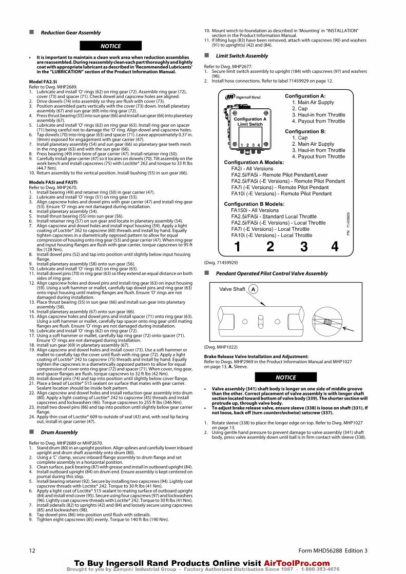
n Limit Switch Assembly
Refer to Dwg. MHP2677.1. Secure limit switch assembly to upright (184) with capscrews (97) and washers
(96).2. Install hose connections. Refer to label 71459929 on page 12.
(Dwg. 71459929)
n Pendant Operated Pilot Control Valve Assembly
Valve Shaft A
(Dwg. MHP1022)
Brake Release Valve Installation and Adjustment:Refer to Dwgs. MHP2969 in the Product Information Manual and MHP1027on page 13, A. Sleeve.
NOTICE
• Valve assembly (341) shaft body is longer on one side of middle groovethan the other. Correct placement of valve assembly is with longer shaftsection located toward bottom of valve body (339). The shorter section willprotrude up, through valve body.
• To adjust brake release valve, ensure sleeve (338) is loose on shaft (331). Ifnot loose, back off (turn counterclockwise) setscrew (337).
1. Rotate sleeve (338) to place the longer edge on top. Refer to Dwg. MHP1027on page 13.
2. Using gentle hand pressure to prevent damage to valve assembly (341) shaftbody, press valve assembly down until ball is in firm contact with sleeve (338).
12 Form MHD56288 Edition 3

Sleeve A
(Dwg. MHP1027)
CAUTION
• Do not disassemble pilot cap assemblies. Valve cylinder and valve cap arepress fit together. Close fit tolerances cannot be maintained ifdisassembled. If repair is required, replacement of the pilot cap assemblyis required.
Pendant Valve Adjustment:1. Lubricate threads and install capscrews (366) and (368), lockwashers (924),
gasket (340) and pilot cap assembly (367) to valve body (339). Tighten capscrew,but do not torque.
2. Reaching into exhaust port on valve body (339), grasp shaft (331) and check formovement in either direction. Any movement requires adjustment.
3. If there is shaft movement, remove pilot cap assembly and back out setscrewsin pistons 1/4 turn. Repeat until there is no movement.
4. When adjustment is complete, tighten capscrews (366) and (368). Refer to“TORQUE CHART” on page 15 for torque requirements.
Adapter Installation:1. Place gasket (358) on mating face of adapter (369) and align holes with valve
body (339). Coat threads with Loctite® 242 and, from the bottom side of adapter,install capscrews (370) into valve body. Refer to“TORQUE CHART” on page 15 for torque requirements.
n Two Function Pendant Assembly
Refer to Dwg. MHP1677 with emergency stop or MHP2346 without emergency stop.1. Install ‘O’ rings (443) and (449) along with protector (451) on valves (452). Install
valve assemblies in handle (454)2. Install levers (453) in pendant handle (454) with pin (447). Stake pin in pendant
handle at both ends to secure.3. Install screws (448) in levers.4. Install balls (446) and springs (445) in handle (454). Secure in position with plugs
(444).5. On pendants with emergency stop, install emergency stop button (441). On
pendants without emergency stop, install plug (470).6. Install exhaust washer (457) and secure in handle with retainer ring (458).7. Attach hoses to fittings located on top of pendant handle. Locate hoses to fittings
as shown in Dwg. MHP2398 in Product Information Manual.
n Press Roller Assembly
Refer to Dwgs. MHP2695.Two people are recommended when installing press roller assembly.1. If bushings (410) have been removed, replace and install in uprights (42) and
(84) and in both ends of arm (407). Grease bushings (410) for ease of installation.2. Install rollers (402) on smaller ends of press roller arm (407) and secure with
capscrews (408) and washers (409). Apply a small amount of Loctite® 242 tothreads of capscrews.
3. Install springs (405) and (406) so shorter end of springs are toward tabs on innerportion of arm (407).
4. Position press roller so top of arm (407) is curved up toward the under side ofdrum (80). One person must hold press roller in place while the other personcompletes installation.
5. Adjust both springs (405) and (406) so long end of springs are on inside of siderail(82).
NOTICE
• Do not engage shorter end of spring behind tabs of arm (407) until aftershaft (403) has been installed and secured and press roller assembly isadjusted to center of drum.
6. Install shaft (403) through hole in leg of upright (84) only.7. Install one collar (404) on end of shaft (403) between upright and press roller
assembly. Do not tighten collar (404) until steps 10 and 11 have been completed.8. Install shaft (403) through press roller assembly (400).9. Install second collar (404) and slide shaft through hole in leg of upright (42).
Ensure that long end of springs (405) and (406) are still between siderail (82) anddrum (80). Do not tighten collar (404) until steps 10 and 11 have been completed.
10. Secure shaft (403) to uprights using capscrews (408) and washers (409). Apply asmall amount of Loctite® 242 to threads of capscrews.
11. Adjust press roller assembly so it is centered between the drum flanges andcollars (404).
12. Tighten collars (404).13. Using extreme caution, pry short end of one spring (405) so it is positioned
behind the tab of arm (407).14. Repeat step 13 for spring (406).
CAUTION
• Use caution when installing springs (405) and (406). Springs are undertension.
n Winch Assembly
Refer to Dwg. MHP2689 or MHP2670 and MHP2674.1. Clean both mating surfaces on inboard upright (42) and install drum shaft (41)
through bore aligning dowel pin holes.2. Install dowel pins (40) flush or slightly below surface of drum shaft (41).3. Install eight capscrews (39). Lightly coat capscrew threads with Loctite® 242 and
torque to 80 ft lbs (108 Nm).4. Press bearing (37) onto drive shaft (35). Lightly coat inner bearing race bore with
Loctite® 609. Install retainer ring (38).5. Install shaft and bearing into drum shaft (41) so smaller splined end enters first.
Install retainer ring (36) in bore of drum shaft (41).
Instructions 6 through 17 cover winches with a disc brake. For wincheswithout a disc brake skip to instruction 18.
6. Install gear (21) so splined side on outside diameter goes on first. Install capscrewin collar (13) and place on shaft (35). Maintain pressure on collar to keep it againstgear and tighten capscrew in collar.
7. Lubricate and install ‘O’ ring (33) on hub of drum shaft (41).8. Install brake housing (17) on drum shaft (41) being careful not to damage ‘O’
ring (33).9. Position brake housing so brake port is in the 2 o’clock position (as viewed from
the motor end). Install drain plug (31) in brake housing at the 6 o’clock position.10. Install reducer fitting (28) and breather (29) in top of brake housing (17).11. Lubricate friction plates (19) with a light motor oil (refer to ‘Recommended
Lubricants’ in Product Information Manual. Install friction plates (19) and driveplates (18) in brake housing (17). Begin with a friction plate then alternate withdrive plates between friction plates. Ensure splined teeth mesh. Do not forceplates into place during installation.
12. Lubricate and install seals (11) and (12) in brake piston (10) grooves so seal lipsface each other. Do not overstretch seals during this procedure. Refer to Dwg.MHP0139 on page 14.
13. Install brake piston assembly in brake housing so stepped side enters first. Gentlytap into position using a soft mallet until seated.
14. Install one brake spring (9) in each brake spring holes.15. Lubricate and install ‘O’ ring (33) in groove on brake housing (17).
NOTICE
• ‘O’ ring, item (33) listed in step 15 refers to part number 51460 as shown onDwgs. MHP2689 and MHP2670. This part must be placed between brakehousing (17) and motor adapter (6).
Form MHD56288 Edition 3 13

Brake Seal Installation
Seal Lip
Seal
BrakePiston
A
BC
(Dwg. MHP0139)
16. Install brake reaction plate (8) in motor adapter (6).17. Install seal adapter (15) in mounting flange (216), if required.18. Two threaded holes in motor adapter (6) are centered between mounting bolt
holes. Install motor adapter with these two holes in the 6 o’clock position.19. Secure motor adapter with eight capscrews (93) using Loctite® 242. Torque to
125 ft lbs (170 Nm). On winches with a disc brake, install capscrews evenly tocompress brake springs and torque to 80 ft lbs (108 Nm). Do not allow plate tobecome cocked. Evenly hand tighten all capscrews before applying final torque.
20. On disc brake equipped winches, install shaft (7) on end of drive shaft (35). Onwinches without disc brake, install seal sleeve (14) on drive shaft (35).
21. Lubricate and install ‘O’ ring (5) in groove on motor adapter (6).22. Ensure seal adapter (15) and oil seal (2) are installed in bore of motor assembly.
Seal lip must face into motor assembly.
WARNING
• The air motor weighs approximately 260 lb (118 kg). Adequately supportair motor while installing motor mounting capscrews.
23. Place gasket (226) on mounting flange (216) and align holes.24. If motor assembly is being mounted with winch in a vertical position, install one
short bolt and nut to keep motor mounting flange (216) from dropping off.Lower motor assembly carefully onto drive shaft (35). Position throttle assemblyat the top. Be careful not to damage oil seal (2). When correctly positioned,remove bolt and nut and lower motor assembly the remaining distance.
25. Install the motor assembly to motor mounting plate using capscrews (4) andlockwashers (3). Lightly coat capscrew threads with Loctite® 242 and torque to85 ft lbs (115 Nm).
26. On winches with a disc brake, install level/drain plug fitting (31). Install dumpvalve (26) and nipple fitting into brake release port. Install vented fitting (27) indump valve (26). Install elbow fitting (956) in control valve assembly (900) or(908). Install vented fitting (27) between dump valve (26) and hose assembly (44)or tubing assembly (64).
n Guard Assembly
Refer to Dwgs. MHP2676.1. Secure frames (801) and (802) to uprights (42) and (84) with capscrews (809) and
washers (96).
2. Install panels (805) and (807), one at a time, beginning with either the upper(807) or lower (805) panel.a. Install first crossbar (806) with nuts (804).b. Attach panel to crossbar (806).c. Holding second panel (805) in place, install second crossbar (806) by sliding
through hooked edges of the two panels.d. Secure crossbar (806) with nuts (804).e. Continue until all panels are in place.
3. Tighten all fasteners and check winch guard is secure. Ensure wire rope does notinterfere with winch guard during winch operation.
n Testing
n Operational Test
Prior to initial use, all new, altered or repaired winches shall be tested to ensureproper operation.
a. Check oil level in motor, reduction gear assembly and disc brake are correct.b. To initially ‘break in’ new or overhauled motors, operate without load, in
both directions, for 15 minutes at 100 - 200 RPM.c. New Brake Band Lining Run-in Procedure: All new brake band linings require
a ‘run-in’ period.d. Operate the winch without load in the payout direction while gradually
applying the brake. Allow the brake to slip for approximately one minute.Winch motor may stall as brake band lining fully engages. Do not allow braketo overheat.
e. Check operation of brakes. Adjust if necessary as described in the“MAINTENANCE” section.
f. Check operation of limit switches, locking devices and all safety deviceswhen equipped.
g. Check foundation mounting fasteners are secure.h. Install winch guard.
n Load Test
Prior to initial use, all extensively repaired winches shall be load tested by or underthe direction of an Ingersoll Rand trained Technician and a written report furnishedconfirming the rating of winch. Test loads shall not be less than 100% of rated linepull and should not exceed 125% of rated line pull. To test winch at 125% of ratedload apply following load with wire rope on the first layer of the drum:
FA2.5i, -E, and CE (Utility and Man Rider) @ 6,600 lb. (2,994 kg)
FA2.5i-MR-E (Man Rider) @ 4,183 lb. (1,899 kg)
FA5i, and -E (Utility) @ 15,800 lb. (7,167 kg)
FA5i-MR and MR-E (Man Rider) @ 8,567 lb. (3,886 kg)
FA5i-CE (Utility and Man Rider) @ 15,900 lb. (7,212 kg)
FA5Ti and -E (Utility) @ 15,800 lb. (7,167 kg)
FA5Ti-CE (Utility) @ 15,900 lb. (7,212 kg)
NOTICE
• Testing to more than 125% of rated line pull may be required to set overloaddevice or comply with standards and regulations set forth in areas outsideof the USA.
n Limit Switches
Operate winch through three complete cycles to ensure consistent limit switchoperation within +/- 2 feet (0.6 m) of set points. Refer to 'Limit Switch Adjustment'procedure in Product Information Manual to establish set points.
14 Form MHD56288 Edition 3

TORQUE CHART
Standard Coarse Thread Torque
SizeSAE Grade 5 SAE Grade 8
Dry Lubricated PTFE Dry Lubricated PTFE1/4-20 8-10 6-7 4 12-14 9-10 5-6
5/16-18 17-20 13-15 8-9 25-28 18-21 11-133/8-16 31-35 23-26 14-16 44-49 33-37 20-22
7/16-14 49-56 37-42 22-25 70-79 52-59 31-361/2-13 75-85 57-64 34-38 106-121 80-90 48-54
9/16-12 109-123 82-92 49-55 154-174 115-130 69-785/8-11 150-170 113-128 68-77 212-240 159-180 95-1083/4-10 267-302 200-227 120-136 376-426 282-320 169-1927/8-9 429-487 322-365 193-219 606-687 455-515 273-309
1-8 644-729 483-547 290-328 909-1030 681-772 409-4631 1/8-7 794-900 596-675 357-405 1288-1460 966-1095 580-6571 1/4-7 1121-1270 840-952 504-571 1817-2059 1363-1545 818-927
Standard Fine Thread Torque
SizeSAE Grade 5 SAE Grade 8
Dry Lubricated PTFE Dry Lubricated PTFE1/4-20 10-11 7-8 4-5 14-15 10-12 6-7
5/16-24 19-22 14-16 9-10 27-31 20-23 12-143/8-24 35-40 26-30 16-18 49-56 37-42 22-25
7/16-20 55-63 41-47 25-28 78-88 58-66 35-401/2-20 85-96 64-72 38-43 120-136 90-102 54-61
9/16-18 121-137 91-103 55-62 171-194 128-146 77-875/8-18 170-193 127-144 76-87 240-272 180-204 108-1223/4-16 297-337 223-253 134-152 420-476 315-357 189-2147/8-14 474-537 355-403 213-242 669-758 502-568 301-341
1-12 704-798 528-599 317-359 995-1127 746-845 448-5071 1/8-12 1023-1159 767-869 460-572 1444-1637 1083-1227 650-7361 1/4-12 1425-1615 1069-1211 641-727 2012-2280 1509-1710 905-1026
Metric Coarse Thread Torque
SizeClass 8.8 / 9.8 Class 10.9
Dry Lubricated PTFE Dry Lubricated PTFEM6x1 9-10 6-7 4 11-12 8-9 5-6
M8x1.25 21-23 16-18 9-11 26-30 20-22 12-13M10x1.5 41-47 31-35 19-21 53-60 39-45 24-27
M12x1.75 71-81 54-61 32-36 91-103 68-77 41-46M14x2 115-130 86-98 52-59 147-166 110-125 66-75M16x2 165-187 124-140 74-84 227-257 170-193 102-116
M20x2.5 321-364 241-273 144-164 443-502 332-376 199-226M22x2.5 439-497 329-373 197-224 605-686 454-514 272-309M24x3 556-630 417-473 250-284 767-869 575-652 345-391
M30x3.5 1103-1250 827-938 496-563 1521-1724 1141-1293 685-776Metric Fine Thread Torque
SizeClass 8.8 / 9.8 Class 10.9
Dry Lubricated PTFE Dry Lubricated PTFEM8x1 22-25 17-19 10-11 28-32 21-24 13-14
M10x1.25 44-49 33-37 20-22 56-63 42-47 25-28M12x1.25 78-89 59-67 35-40 100-113 75-85 45-51M14x1.5 125-141 93-106 56-64 159-180 119-135 72-81M16x1.5 176-200 132-150 79-90 243-276 183-207 110-124M18x1.5 257-291 193-219 116-131 355-402 266-302 160-181M20x1.5 358-406 268-304 161-183 494-559 370-420 222-252M22x1.5 484-548 363-411 218-247 667-756 500-567 300-340M24x2 609-690 456-517 274-310 839-951 630-713 378-428M30x2 1227-1390 920-1043 552-626 1692-1918 1269-1438 761-863
Notes:
1. Definitions:DRY: Cadmium plate, zinc plate, and oiled fasteners.LUBRICATED: Molysulfide paste, carnaba wax, molysulfide grease andcopper-based anti-seize coated fasteners.PTFE: 2% minimum PTFE coated fasteners.
2. All torque values foot-pounds unless noted.3. SAE grade 5 equivalent to ASTM A325 Type 2 and ASTM A449.4. SAE grade 8 equivalent to ASTM A354 Grade BD, ASTM A490 Type 1.5. If mixing fasteners use lowest torque value.6. Torque values 75 to 85% of fastener proof load ref.
Form MHD56288 Edition 3 15
![· Web viewPost Until: [Date] PRODUCT RECALL. PRODUCT RECALL. PRODUCT RECALL. PRODUCT LIABILITY EVALUATION. PRODUCT LIABILITY EVALUATION. PRODUCT LIABILITY EVALUATION. PRODUCT LIABILITY](https://static.fdocuments.net/doc/165x107/5e58b356d7aea8615859438c/web-view-post-until-date-product-recall-product-recall-product-recall-product.jpg)