Influence of the Vibro Stone Column Reinforcement on … for seismic loading, a pseudo-static...
10
Influence of the Vibro Stone Column Reinforcement on The the Seismic Bearing Capacity of a Surface Shallow Footing B. Galy & M.J. Nollet École de Technologie Supérieure, Canada D. LeBoeuf Université Laval, Canada D. Lessard Ministère des transports du Québec, QC, Canada SUMMARY: In difficult soil conditions, engineers sometimes choose to combine reinforced soil and spread footings instead of deep foundations. Among the available techniques for soil reinforcement, vibro stone columns are frequently used to reduce the liquefaction risk, improve the soil properties and improve the overall seismic performance. While there are different models available to evaluate the bearing capacity of reinforced soils under static conditions, its evaluation under seismic conditions have been much less investigated. In this communication, a new approach to estimating the bearing capacity of reinforced soils under seismic conditions is proposed. It is based on limit equilibrium theory, pseudo-static and pseudo-dynamic concepts and a specialized method for estimating reinforced soil properties. The method is validated for the pseudo-static case and the results of an extensive parametric study on the dimensions of the reinforced zone are also presented. Keywords: vibro replacement, bearing capacity, Priebe, surface footing 1. INTRODUCTION For regions with moderate to high seismic activity, the evaluation of the bearing capacity of shallow footings under dynamic conditions is a very important task. Indeed, although it is recognized that the bearing capacity may differ under dynamic and static conditions, there are currently no specific recommendations for addressing these distinctions in Canadian codes and standards (CAN/CSA, 2006; NRC, 2005). The AASHTO (2010) recommends accounting for the degradation of geotechnical resistance for some types of soil but does not specify a specific method to evaluate the degradation. The International Building Code (Day, 2006) permits an increase in allowable bearing capacity of 33% under earthquake loading for the design of footings. However, several researchers have shown that the ultimate bearing capacity of soil, also known as the geotechnical resistance, is reduced in the case of dynamic loading (Choudhury and Subba Rao, 2005; 2006; Dormieux and Pecker, 1995; Fishman et al., 2003; Paolucci and Pecker, 1997; Pecker, 1996; Richards et al., 1993). To design a footing for seismic loading, a pseudo-static inclined and off-centered load is generally considered (Fraser Bransby, 2001). The limits of the applicability of this method are relatively unknown and, therefore, much research has recently been conducted on estimating soil bearing capacity under complex combined loads (Bienen et al., 2006; Cassidy et al., 2002; Cassidy et al., 2004a; Cassidy et al., 2004b). This research has led to the development of "failure envelopes" concept representing the three-dimensional plastic limit of soil in a load space H (horizontal load) M (moment) and V (vertical load). Most of these envelope curves are still experimental and accurately represent the behavior of the soil being studied for a pseudo-static plan loading. In difficult soil conditions, and for economic reasons, engineers are sometimes choosing to combine reinforced soil and spread footings instead of deep foundations (Hussin, 2006). The main objective is primarily to build a reinforcing element into the soil. Among the available techniques for soil reinforcement, vibroreplacement with stone columns is well understood and can lead to significantly
-
Upload
truongquynh -
Category
Documents
-
view
220 -
download
2
Transcript of Influence of the Vibro Stone Column Reinforcement on … for seismic loading, a pseudo-static...

Influence of the Vibro Stone Column Reinforcement on
The
the Seismic Bearing Capacity of a Surface Shallow
Footing
B. Galy & M.J. Nollet École de Technologie Supérieure, Canada
D. LeBoeuf Université Laval, Canada
D. Lessard Ministère des transports du Québec, QC, Canada
SUMMARY:
In difficult soil conditions, engineers sometimes choose to combine reinforced soil and spread footings instead of
deep foundations. Among the available techniques for soil reinforcement, vibro stone columns are frequently
used to reduce the liquefaction risk, improve the soil properties and improve the overall seismic performance.
While there are different models available to evaluate the bearing capacity of reinforced soils under static
conditions, its evaluation under seismic conditions have been much less investigated. In this communication, a
new approach to estimating the bearing capacity of reinforced soils under seismic conditions is proposed. It is
based on limit equilibrium theory, pseudo-static and pseudo-dynamic concepts and a specialized method for
estimating reinforced soil properties. The method is validated for the pseudo-static case and the results of an
extensive parametric study on the dimensions of the reinforced zone are also presented.
Keywords: vibro replacement, bearing capacity, Priebe, surface footing
1. INTRODUCTION
For regions with moderate to high seismic activity, the evaluation of the bearing capacity of shallow
footings under dynamic conditions is a very important task. Indeed, although it is recognized that the
bearing capacity may differ under dynamic and static conditions, there are currently no specific
recommendations for addressing these distinctions in Canadian codes and standards (CAN/CSA,
2006; NRC, 2005). The AASHTO (2010) recommends accounting for the degradation of geotechnical
resistance for some types of soil but does not specify a specific method to evaluate the degradation.
The International Building Code (Day, 2006) permits an increase in allowable bearing capacity of
33% under earthquake loading for the design of footings. However, several researchers have shown
that the ultimate bearing capacity of soil, also known as the geotechnical resistance, is reduced in the
case of dynamic loading (Choudhury and Subba Rao, 2005; 2006; Dormieux and Pecker, 1995;
Fishman et al., 2003; Paolucci and Pecker, 1997; Pecker, 1996; Richards et al., 1993). To design a
footing for seismic loading, a pseudo-static inclined and off-centered load is generally considered
(Fraser Bransby, 2001). The limits of the applicability of this method are relatively unknown and,
therefore, much research has recently been conducted on estimating soil bearing capacity under
complex combined loads (Bienen et al., 2006; Cassidy et al., 2002; Cassidy et al., 2004a; Cassidy et
al., 2004b). This research has led to the development of "failure envelopes" concept representing the
three-dimensional plastic limit of soil in a load space H (horizontal load) M (moment) and V (vertical
load). Most of these envelope curves are still experimental and accurately represent the behavior of the
soil being studied for a pseudo-static plan loading.
In difficult soil conditions, and for economic reasons, engineers are sometimes choosing to combine
reinforced soil and spread footings instead of deep foundations (Hussin, 2006). The main objective is
primarily to build a reinforcing element into the soil. Among the available techniques for soil
reinforcement, vibroreplacement with stone columns is well understood and can lead to significantly

improved mechanical soil properties (Kirsch, 2008). These improved soil properties must be
adequately evaluated in order to adopt an efficient design for the spread footings. Vibro stone columns
are also frequently used to reduce the liquefaction risk (Adalier and Elgamal, 2004; Hussin, 2006) and
improve the overall seismic performance, however much uncertainty remains in the geotechnical and
structural design of these foundations elements built on soils reinforced by vibro stone columns.
This problem becomes more particularly acute in Eastern Canada since the seismic loading criteria
have been significantly increased in the 2005 version of the building codes (NRC, 2005). When
designing a surface footing, the first step is to estimate the geotechnical properties of the soil with in
situ testing, lab testing and empirical relationships such as Peck’s. Sometimes a reinforcement of the
soil is needed and in such a case, the modified properties are determined either by in situ testing or by
using mechanical models such as Priebe’s. The third and final step is to compute the bearing capacity
with a plasticity based method. This paper focuses on the last step, and aims at proposing a practical
procedure to evaluate the static and dynamic bearing capacity of shallow foundations on a vibro stone
reinforced soil. This contribution includes a validation for the pseudo-static case and a parametric
study on the plane dimensions of the zone to be reinforced (width and depth) in order to reach the
optimum efficiency in terms of cost and increase in bearing capacity
2. LITTERATURE REVIEW
2.1. Evaluation of the Dynamic Bearing Capacity
2.1.1 Limit equilibrium based method with equivalent pseudo-static loads
There are currently no specific recommendations or guidelines to determine bearing capacity under
dynamic conditions in the codes and standards of Canada (CAN/CSA, 2006; NRC, 2005). In order to
estimate the bearing capacity for a seismic loading, a combined pseudo-static loading is applied to the
foundation (H, M, V), and plasticity based methods for static conditions are then used (AASHTO,
2010). However, it should be noted that under dynamic conditions, the bearing capacity may be less
than (especially in saturated soil) or greater than (in unsaturated soil) the bearing capacity under static
conditions (AASHTO, 2010). In most cases, the design for a seismic load is actually carried out with
equivalent static conditions. However, the duration of vibrations and the number of cycles generated
by earthquakes are relatively short and therefore the risk of soil failure may not be significant
(AASHTO, 2010) and the main problem becomes the occurrence of permanent displacements and/or
rotations of the foundation leading to a redistribution of moments and shear forces in the structure
(AASHTO, 2010). This case would no longer be part of footing design, but its proper evaluation
requires a soil structure interaction analysis. The liquefaction potential of the soil must also be
considered in the design of shallow foundations (AASHTO, 2010; CAN/CSA, 2006; NRC, 2005).
The seismic loading on a structure acts as a horizontal load H and an overturning moment M at the
foundation level. The overturning moment applied to the footing is equivalent to an off-centered
vertical load V. For the seismic design at the ULS, S6-06 guidelines allows an off-centered load with
an offset up to 0.4B (CAN/CSA, 2006). If this condition is satisfied, the footing dimensions are
established by considering a uniform pressure distribution on the reduced footing dimensions B' and L'
as defined by Meyerhof. The center of this surface is equivalent to the point of application of the off-
centered vertical load. The uniform pressure due to factored loads must be less than the factored
ultimate geotechnical strength (’, qult). The S6-06 and the Canadian Foundation Engineering Manual
(CFEM) standards offer similar equations for determining the capacity qult (CGS, 2006). This approach
will be referred to as the CFEM method later in the text.
2.1.2 Pseudo-dynamic approach
For some cases (specially for-saturated soils) the bearing capacity may decrease under seismic
conditions (AASHTO, 2010). This degradation is a complex phenomenon and is partly due to the
presence of inertial forces, straining and pore pressure effects in the soil. Several researchers have
worked on determining "dynamic" bearing capacity factors from the Coulomb failure mechanism,
among them Richards et al. (1993) and Choudhury and Subba Rao (2006). These methods use
dynamic/static bearing capacity factor ratios (NγE/Nγ, for example). These authors emphasize that their
approach is probably conservative but it does allow for the development of safer design procedures for
areas subjected to seismic hazards. For non-cohesive unsaturated soils, the usual pseudo-static
methods are sufficiently safe in most cases. For cohesive soils or saturated sand the risk of degradation
of soil properties should be taken into account (AASHTO, 2010).
The dynamic/static ratio, presented in Fig 2.1, depends on the horizontal and vertical acceleration
coefficients of the earthquake (kh and kv, respectively). As illustrated in Fig 2.1, the bearing capacity
factors decrease rapidly with increasing tanθ where tanθ = kh/(1-kv). Richards et al. state that for a
horizontal acceleration coefficient kh = 0.25, the ultimate bearing capacity is divided by 3.
Figure 2.1. Dynamic / Static Bearing Capacity Factors.
Adapted from Richards et al. 1993.
The advantage of this type of method is the simplicity of its implementation, which allows its
application to be considered in combination with conventional methods described in standards and
design guidelines. However, an experimental validation remains to be carried out. Numerous other
studies have achieved results very similar to those obtained with Richards’ method (Choudhury and
Subba Rao, 2005, 2006; Dormieux and Pecker, 1995; Subba Rao and Choudhury, 2005).
2.2 Vibro Reinforced Soil Parameters Estimation with Priebe’s Method
Priebe’s method consists in the calculation of an improvement factor ‘n’ (Priebe, 1995) to evaluate the
modified properties. This mechanical model is now a German Standard (DIN 4017) and is commonly
used for the design of shallow foundation resting on a reinforced medium. The author specifies 3
different improvement ratios: n0, n1 and n2. The first one, n0, is the “basic improvement factor” and
does not account for some hypotheses. The second one (n1) takes into account the column
compressibility. The last one (n2) adds the consideration of the overburden. These improvement
factors are all function of the area replacement ratio Ac/A, where Ac is the area of soil replaced and A
the total area of the zone reinforced. The equations [2.1] to [2.3] allow the user to compute the
improvement factor n0 plotted in Fig 2.2 as a function of the area replacement ratio and the internal
friction angle of the reinforced soil.
(2.1)
(2.2)
(2.3)

Where μs is the Poisson’s ratio of the soil and φc the internal friction angle of the ballast.
Priebe gives two equations to evaluate the internal friction angle and the effective cohesion of the
composite system. Those two equations are given below [2.4 and 2.5]. Using those parameters for the
composite system, it is possible to evaluate the bearing capacity for a homogeneous equivalent soil.
Figure 2.2. Improvement factor n0 as a function of the area replacement ratio and internal friction angle.
Adapted from Priebe 1995.
( ) (2.4)
( ( )) (2.5)
Where m’=(n-1)/n, is the internal friction angle of the composite system, is the friction angle of
the ballast, is the friction angle of the soil, and is different from and is defined in Priebe
1995. Baez Satizabal (1995) proposed another method to evaluate the properties of the soil after
reinforcement. This method is not presented herein but a short review and a comparison with Priebe’s
method is available elsewhere (Galy et al.,2012).
3. A PRATICAL PROCEDURE FOR EVALUATING THE SEISMIC BEARING CAPACITY
OF SHALLOW FOOTINGS ON STONE REINFORCED SOILS
3.1 Presentation of the Proposed Procedure
As listed in Section 2, different methods were developed in order to take into account the inertial
forces occurring in the soil during an earthquake and the soil improvement properties induced by the
installation of vibro stone columns. This paper proposes a practical procedure to evaluate the ultimate
bearing capacity that includes the dynamic effects and the soil reinforcement. This procedure is
summarized in Fig 3.1. The first step is to compute the improvement factor n1 or n2 according to
Priebe’s equations or to compute the N1/60 after reinforcement according to Baez’s model. In step 2,
from either n or N, the user is able to compute the modified geotechnical properties of the reinforced
soil (composite system in Priebe’s case). In step 3 the user can compute the static and/or pseudo-
dynamic bearing capacity factors. In the final step, the user computes the bearing capacity as usual
with the CFEM method, using the reinforced geotechnical properties estimated for the composite
system and the bearing capacity factors computed in step 3.
In this approach, the Richards’s method, which has been supported by numerous studies (as indicated
in Section 2.1), is combined with the CFEM method by applying the dynamic/static ratios to the

bearing capacity factors of Fig 2.1. By its nature, this method is only approximate for complex
geometries and loadings (Fraser Bransby, 2001). Nevertheless, the proposed procedure could give to
the designer a good indication on the safety of the foundation. In Fig 3.1, Peck’s equations relating the
internal friction angle to the SPT results is used (Peck et al., 1974).
Figure 3.1. Evaluation of the bearing capacity for a reinforced soil in static conditions (Method A) and pseudo-
dynamic conditions (Method B).
Priebe’s and Baez Satazabal’s methods have been proved to be quite accurate for static conditions
(Baez Satizabal, 1995; Kirsch, 2008). However, the estimation of the ultimate bearing capacity is not
the primary goal of these different methods and the procedure proposed in this paper requires a
validation. Finally there is also a need for a validation of the estimation of the ultimate bearing
capacity of reinforced soil in a dynamic condition. The dynamic validation (using the pseudo-dynamic
bearing capacity factors from Richards et al.(1993)) is actually under study and will not be presented
in this contribution.
3.2 Validation of the Proposed Procedure with a Finite Difference Model
This section presents a comparison between the bearing capacity obtained with the Method A of the
proposed procedure (Fig. 3.1) and a 2D Finite Difference Model using FLAC software (Itasca, 2006).
The techniques adopted in order to compute the bearing capacities are presented in Fig 3.2. The two
numerical models (a) and (b) used in the software FLAC are detailed in this section.
Figure 3.2. Computation of the bearing capacities with different techniques.
Two different numerical models were used in order to represent the differences of the methods
proposed by Baez and Priebe respectively. Baez’s equations allow the designer to compute the
estimated results to a SPT or CPT after reinforcement for the soil located between the stone columns.
Therefore, the post reinforcement soil parameters should give a lower bound bearing capacity for
purely un-cohesive soils. Priebe’s method gives an internal friction angle for the composite system for
Priebe / Baez
n1 or n
2 / N
1/60
Priebe / Peck
Φ' c' / Φ'
Richards
Computation of NS/N
E
ratios with the new Φ'
CFEM
Computation of NS
with the new Φ'
CFEM
Computation of the ultimate bearing capacityusing the new N
S and soil parameters
Priebe / Baez
n1 or n
2 / N
1/60
Priebe / Peck
Φ' c' / Φ'
CFEM
Computation of NS
with the new Φ'
CFEM
Computation of the ultimate bearing capacityusing the new N
S and soil parameters
Method A Method B

the soil and the stone columns. This has been modeled as a homogeneous equivalent soil in the finite
difference model. The two numerical models are presented in Fig 3.4.
The footing considered has a width of 0.45 m and is a strip footing. The model uses the symmetry of
the problem and thus only a half of the foundation and the soil are represented. The model has a width
and a height of 5 m. The grid is square and homogeneous for the far field and has a width of 0.25 m.
Underneath the foundation (2m deep and 1.5 wide) the grid is still square and homogeneous but it is
five times smaller and has a width of 0.05m. Numerous sensitivity analyses have been performed in
order to ensure that the dimensions of the grid do not impact the results. It has been found that
homogeneous grids give good results in order to estimate the bearing capacity with FLAC as it has
been emphasized by Frydman and Burd (1995) and Yin et al. (2001). Although this foundation is
relatively small, larger widths have been studied and the results are very similar to those obtained with
this model. A Mohr-Coulomb model represents the soil.
The foundation is supposed to be a smooth footing therefore the nodes are only constrained in the
vertical direction under the footing (Frydman and Burd, 1995). The internal friction angle values of
the stone column are generally included between 40 and 50° but a relatively low value is generally
considered (mostly 40 or 42°) in order to have conservative estimates (McCabe et al., 2007).
Model (a) is made of a homogeneous equivalent reinforced soil underneath the foundation (2 x 1,5m)
and homogeneous fluvio-glacial sand for the unreinforced part. Since we only take interest in the
ultimate bearing capacity, the plastic components (E and ν) do not influence the results and we can just
modify the internal friction angle in order to represent the reinforced soil. Model (b) is made of
reinforced soil between the columns (using the φ' estimated with Baez’s method and Peck’s equation
(Peck et al. 1974)).
Figure 3.4. 2D FDM FLAC models used in this study.
The two FDM give very similar results: the maximum difference between the bearing capacities
computed with FLAC is 12,4%. The CFEM Priebe method is the one that gives the best results, in
comparison with the FDM, and the maximum difference between the CFEM Priebe and FLAC Priebe
methods is 5,5%. Those results show that Method A appears to be efficient for estimating the bearing
capacity of a vibro stone reinforced soil in pseudo-static conditions.
Priebe Baez

4. INFLUENCE OF THE REINFORCED ZONE DIMENSIONS ON THE BEARING
CAPACITY
4.1 Scope and Limitations of the Parametric Study
The parametric study includes the two case scenario presented in Fig 4.1. The first case corresponds to
a full soil treatment before the installation of the shallow footing and is referred to as scenario “1” [Fig
4.1 (a)]. The second scenario (“2”) corresponds to partial soil improvement. Scenario “2” is
encountered most frequently in rehabilitation projects as the access to the soil below the footing is
more difficult and more costly [Fig 4.1 (b)].
(a) (b)
Figure 4.1. “Full” (a) and “partial” (b) soil improvement scenario
The results for this parametric study were obtained with the FDM Model (a) (Priebe) presented in Fig
3.4 varying the plane dimensions of the reinforced area, width (W) and depth (D), both function of the
footing width B. A total of 288 models (Priebe) were used to conduct this parametric study and 42
Baez models were used in order to validate the results. The maximum difference between the results
obtained with those two series of models was 8%.
4.2 Results
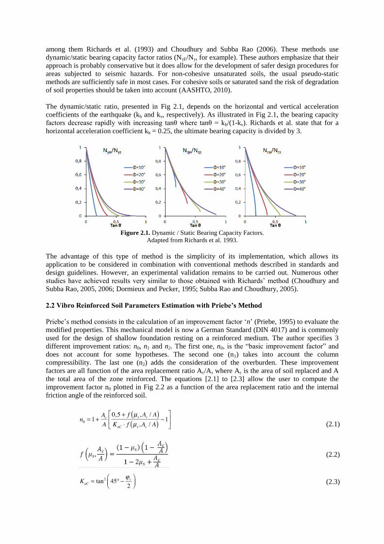
The computed bearing capacities are function of three parameters: the reinforcement width W, the
reinforcement depth D, and the area replacement ratio Ar. For concision only the results from the
“partial improvement” scenario are presented in this paper. As underlined in Section 4.1, W and D are
a function of the footing width B, meaning that when D=2 on the graph, the treatment depth is in fact
two times B. The computed bearing capacities are presented in Fig 4.2 as surface planes for three
values of the area replacement ratio Ar, 10%, 20% and 30%.
Several observations can be drawn from Fig 4.2. First, as expected, it can be seen that the bearing
capacity increases when the dimensions of the reinforced zone increase (increase in D and W).
Increasing the treatment depth D from B to 3.5B increases the bearing capacity of approximately 5%
for a fixed treatment width. When the treatment width is increased from 0.25B to 2.5B an increase of
10 to 20% can be observed in the bearing capacity (depending on the area replacement ratio chosen). It
also can be noted that past a 1.5B width of treatment the increase in the bearing capacity is negligible.
Those conclusions are valid for the increase in bearing capacity post reinforcement and not for the
liquefaction mitigation effects by vibroreplacement a case that may need a larger treated zone. Very
similar observations can be drawn for the “full improvement” scenario.
Figure 4.2. Bearing capacity qu as a function of the dimensions of the reinforced zone (W and D) and the area
replacement ratio Ar for a “partial improvement” scenario.
The obtained bearing capacities have been compared to those computed with Method A. The ratio of
the bearing capacities is called Rqu and equals the bearing capacity computed with FLAC divided by
the bearing capacity computed with Method A. This ratio can be used by the user to refine the bearing
capacity estimation with Method A. This ratio is plotted in Fig. 4.4 as a function of W, D and Ar. The
equations of the parametric curves presented in Fig 4.3 are obtained from Equation 4.1 and Table 4.1.
( ) (4.1)
The constant values CXX are given in Table 4.1 for both scenarios. The adjusted coefficient of
determination R2 is above 0.98 for all the cases studied. Some comments can be made on Fig 4.3. First
it can be observed that Method A overestimates the bearing capacity (Rqu smaller than 1.0) and that
the use of a correction coefficient (calculated with Equation 4.1) is necessary. The highest area
replacement ratio (Ar=30%) gives the highest overestimation of the bearing capacity for a partial
improvement case (Rqu=0,55). It should be noted that the corresponding curves for the “full
improvement” scenario, not presented herein, are quite different from those in Fig 4.3 for the “partial
improvement” scenario.
Table 4.1. Constant parameters values for the parametric curves
C00 C10 C01 C20 C11 C30 C21
R2
(adjusted)
“Full
improvement”
Ar=10% 0,5127 0,4619 0,002344 -0,128 0,01832 0,01161 -0,00219 0,9888
Ar=20% 0,3159 0,5924 -0,002823 -0,1585 0,01933 0,01408 -0,002247 0,9904
Ar=30% 0,2184 0,6464 -0,004997 -0,1692 0,01912 0,01487 -0,002206 0,9913
“Partial
improvement”
Ar=10% 0,7382 0,2173 0,008664 -0,1188 0,009061 0,02163 -0,0026 0,9985
Ar=20% 0,6159 0,2523 0,004488 -0,1264 0,009968 0,02103 -0,002889 0,9984
Ar=30% 0,5469 0,2675 0,004309 -0,1219 0,005555 0,01803 -0,001393 0,9976
D W
qu
Ar=30% Ar=20%
Ar=10%

Figure 4.3. Bearing capacity ratios Rqu as a function of the dimensions of the reinforced zone (W and D) and the
area replacement ratio Ar for a “partial improvement” scenario.
5. CONCLUSIONS AND FUTURE WORK
A new practical procedure to compute the ultimate bearing capacity of a vibro stone reinforced soil for
static and pseudo-dynamic conditions has been introduced in this contribution. It combines the well
know plasticity based approach presented in the CFEM, Richard’s method to estimate the dynamic
bearing capacity and Priebe’s or Baez’s method to estimate the vibro stone reinforced soil parameters.
The static case was validated using FDM. The results indicate that the proposed practical procedure
differs only by 5,5% from the results obtained with the FDM. The parametric study presented
indicates that a 1.5B treatment width on each side of the footing is sufficient to increase the original
bearing capacity by 25 to 50% (depending on the Ar) in the case of a “partial improvement” scenario
presented here. Furthermore, the parametric surfaces obtained allow the user to compute a correction
factor in order to adjust the bearing capacity computed with Method A. A validation of Method B is
currently under study and will be the object of another paper.
AKCNOWLEDGEMENT
We would like to acknowledge the financial support provided by the Ministry of Transportation of Quebec for
the realization of this research.
REFERENCES
AASHTO, American Association of State Highway and Transportation Officials. (2010), AASHTO LRFD
bridge design specifications, 4th. Washington, DC: American Association of State Highway and
Transportation Officials
Adalier, K.,& Elgamal, A. (2004), Mitigation of Liquefaction and Associated Ground Deformations by Stone
Columns. Engineering Geology, 72: 3-4, 275-291.
Baez Satizabal, Juan Ivan. (1995), A design model for the reduction of soil liquefaction by vibro-stone columns.
D W
Rqu
Ar=10%
Ar=20%
Ar=30%

Ph.D. United States - California, University of Southern California, 207 p.
Bienen, B., B. W. Byrne, G. T. Houlsby & M. J. Cassidy. (2006), Investigating six-degree-of-freedom loading of
shallow foundations on sand. Geotechnique, 56: 6, 367-379.
CAN/CSA, Association canadienne de normalisation, Conseil canadien des normes. (2006), Code canadien sur
le calcul des ponts routiers, 10e éd. Coll. « Norme nationale du Canada ». Mississauga, Ont.:
Association canadienne de normalisation.
Cassidy, M. J., B. W. Byrne & G. T. Houlsby. (2002), Modelling the behaviour of circular footings under
combined loading on loose carbonate sand. Géotechnique, 52: 10, 705-712.
Cassidy, M. J., C. M. Martin & G. T Houlsby. (2004a), Development and application of force resultant models
describing jack-up foundation behaviour. Marine structures, 17, 165-193.
Cassidy, M.J., B. W. Byrne & M. F. Randolph. (2004b), A comparison of the combined load behaviour of
spudcan and caisson foundations on soft normally consolidated clay. Geotechnique, 54: 2, 91-106.
CGS, Canadian Geotechnical Society. (2006), Canadian Foundation Engineering Manual, 4th
edition.
Choudhury, D. & K. S. Subba Rao. (2005), Seismic bearing capacity of shallow strip footings. Geotechnical and
Geological Engineering, 23, 403-418.
Choudhury, D. & K. S. Subba Rao. (2006), Seismic Bearing Capacity of Shallow Strip Footings Embedded in
Slope. International Journal of Geomechanics, May/June, 176-184.
Day, R. W. (2006), Foundation Engineering Handbook - Design and Construction with the 2006 International
Building Code.
Dormieux, L., & A. Pecker. (1995), Seismic Bearing Capacity of Foundation on Cohesionless Soil. Journal of
Geotechnical Engineering, 121: 3, 300-303.
Fishman, K. L., R. Jr Richards & D. Yao. (2003), Inclination factors for seismic bearing capacity. Journal of
geotechnical and geoenvironmental engineering, 129, 861-866.
Fraser Bransby, M. (2001), Failure Envelopes and Plastic Potentials for Eccentrically Loaded Surface Footings
on Undrained Soil. International Journal for Numerical and Analytical Methods in Geomechanics, 25:
4, 329-346.
Frydman, S., & H.J. Burd. (1995), Numerical studies of the bearing capacity factor Ny. Report No. OUEL:
2054/95. Oxford: University of Oxford, Department of Engineering Science.
Galy, B., M.-J. Nollet, D. LeBoeuf & D. Lessard. (2012), Influence of the vibro stone column reinforcement on
the seismic bearing capacity of typical Quebec soils. Annual General Conference of the Canadian
Society of Civil Engineering. (Edmonton), p. 10.
Hussin, J. D. (2006), Methods of Soft Ground Improvement. The Foundation Engineering Handbook. p. 529-
565. Taylor & Francis Group.
Itasca. (2006), Fast Lagrangian Analysis of Continua : User’s Guide. - Version 6.0
Kirsch, F. (2008), Evaluation of Ground Improvement by Groups of Vibro Stone Columns using Field
Measurements and Numerical Analysis. 2nd International Workshop on Geotechnics of Soft Soils -
Focus on Ground Improvement. (University of Strathclyde, Glasgow, Scotland).
McCabe, B., J.A. McNeill & J.A. Black. (2007), Ground improvement using the vibro-stone column technique.
Joint meeting of Engineers Ireland West Region and the Geotechnical Society of Ireland. (NUI Galway,
15 March 2007).
CNRC. (2005), National Building Code of Canada. National Reasearch Council of Canada.
Paolucci, R., & Pecker, A. (1997), Soil inertia effects on the bearing capacity of rectangular foundations on
cohesive soils. Engineering Structures, 19: 8, 637-643.
Peck, R. B., Hanson, W. E. and Thornburn, T. H., (1974), Foundation Engineering, 2nd Edition, John Wiley &
Sons, New York.
Pecker, A. (1996), Seismic bearing capacity of shallow foundations. Eleventh world conference on earthquake
engineering.
Priebe, Heinz J. . (1995), The Design of vibro replacement. Coll. « Ground Engineering »: GeTec, 17 p.
Richards, R. Jr., D. G. Elms & M. Budhu. (1993), Seismic Bearing Capacity and Settlements of Foundations.
Journal of Geotechnical Engineering, 119: 4, 662-674.
Subba Rao, K. S., & D. Choudhury. (2005), Seismic passive earth pressures in soils. Journal of geotechnical and
geoenvironmental engineering, 131: 1, 131-135.
Yin, J-H., Y-J. Wang et A. P. S. Selvadurai. (2001), Influence of nonassociativity on the bearing capacity of a
strip footing. Journal of geotechnical and geoenvironmental engineering, 127: 11, 985-989.

![Failures Resulting From Static Loading [Compatibility Mode]](https://static.fdocuments.net/doc/165x107/54ea1caa4a7959e7158b4c6b/failures-resulting-from-static-loading-compatibility-mode.jpg)


