
INERGEN 200-BAR SYSTEMS -...
80
INERGEN 200-BAR SYSTEMS Component Sheet Library One Stanton Street / Marinette, WI 54143-2542, USA / +1-715-735-7411 / www.ansul.com Copyright © 2013 Tyco Fire Products LP. / All rights reserved. / Form No. PN430149 Component Sheets
Transcript of INERGEN 200-BAR SYSTEMS -...
INERGEN 200-BAR SYSTEMSComponent Sheet Library
One Stanton Street / Marinette, WI 54143-2542, USA / +1-715-735-7411 / www.ansul.comCopyright © 2013 Tyco Fire Products LP. / All rights reserved. / Form No. PN430149 Component Sheets

Form No. PagesI. COMPONENTS 1-1 – 1-33CV-98 CYLINDER SHIPPING ASSEMBLY F-2001249-2 1-1
CV-98 CYLINDER SHIPPING ASSEMBLY – BIS APPROVALS F-2011149-1 1-1.1
AUTOPULSE CONTROL SYSTEM F-2001250 1-2
ANSUL AUTOMAN II-C RELEASING DEVICE F-2001251-2 1-3
SELECTOR VALVES F-2001252-3 1-4
PRESSURE OPERATED STACKABLE ACTUATOR F-2001253-2 1-5
SELECTOR VALVE PNEUMATIC ACTUATION LINE KIT F-2012054 1-5.1
BOOSTER ACTUATOR F-2001254-2 1-6
HF ELECTRIC ACTUATOR F-2001255-2 1-7
LEVER RELEASE ACTUATOR F-2001256-3 1-8
MANUAL PULL BOX F-2001257-2 1-9
CABLE WITH SWAGED END FITTING F-2001258-2 1-10
CORNER PULLEY F-2001259-2 1-11
DUAL/TRIPLE CONTROL BOXES F-2001260-2 1-12
REMOTE CABLE PULL EQUALIZER F-2001261-2 1-13
PRESSURE BLEEDER PLUG – 1/4 IN. F-2001262-2 1-14
FLEXIBLE DISCHARGE BEND F-2001263-2 1-15
CHECK VALVES F-2001264-2 1-16
HEADER VENT PLUG F-2001265-2 1-17
MANIFOLD RELIEF VALVE – 200 BAR F-2004098-1 1-17a
STAINLESS STEEL ACTUATION HOSE F-2001266-2 1-18
PRESSURE REDUCER/UNION F-2001267-2 1-19
PRESSURE REDUCER/NIPPLE F-2005135-1 1-19a
FLANGED PRESSURE REDUCER F-2001269 1-20
DISCHARGE NOZZLE – 360° F-2001272-2 1-21
180° DISCHARGE NOZZLE F-2001273-2 1-22
NOZZLE DEFLECTOR SHIELD F-2001274-2 1-23
CYLINDER BRACKETING F-2001275-3 1-24
PRESSURE SWITCH – DPST F-2001276-2 1-25
PRESSURE SWITCH – DPDT-EXPLOSION-PROOF F-2001277-2 1-26
PRESSURE SWITCH – 3PST F-2001278-2 1-27
PRESSURE TRIP F-2001279-2 1-28
PRESSURE TEST ASSEMBLY F-2001280-2 1-29
PRESSURE-OPERATED SIREN F-2012013 1-29.1
NAMEPLATE – MAIN F-2001283-2 1-30
NAMEPLATE – RESERVE F-2001284-2 1-31
WARNING PLATE – INSIDE ROOM WITH ALARM F-2001285-2 1-32
WARNING PLATE – OUTSIDE ROOM WITHOUT ALARM F-2001286-2 1-33

CV-98 INERGEN Valve
The CV-98 valve has a ten (10) year warranty. The valverequires no internal maintenance. The valve is sealedclosed and must not be disassembled. If there is ever amalfunction of the CV-98 valve, the complete valve must besent back to ANSUL for warranty replacement. If the exter-nal seal is broken, the warranty is voided.
System ComponentsUL EX-4510 2-1-12 Page 1-1
REV. 2
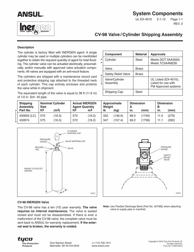
Note: Use Flexible Discharge Bend (Part No. 427082) when attachingvalve to supply pipe or manifold.
Description
The cylinder is factory filled with INERGEN agent. A singlecylinder may be used or multiple cylinders can be manifoldedtogether to obtain the required quantity of agent for total flood-ing. The cylinder valve can be actuated electrically, pneumati-cally, and/or manually with approved valve actuation compo-nents. All valves are equipped with an anti-recoil feature.
The cylinders are shipped with a maintenance record cardand protective shipping cap attached to the threaded neckof each cylinder. This cap entirely encloses and protectsthe valve while in shipment.
The equivalent length of the valve is equal to 38 ft (11.6 m)of 1/2 in. Sch. 40 pipe.
CV-98 Valve / Cylinder Shipping Assembly
Component Material Approvals
Cylinder Steel Meets DOT 3AA3000;Meets TC3AAM230
Valve Brass
Safety Relief Valve Brass
Valve/Cylinder UL Listed (EX-4510);Assembly Listed for use with
FM Approved systems
Shipping Cap Steel
Shipping Nominal Cylinder Actual INERGEN Approximate Dimension DimensionAssembly Size Agent Quantity Weight A BPart No. ft3 (m3) ft3 m3 lb (kg) in. (mm) in. (mm)
430952 (LC) 575 (16.3) 572 (16.2) 322 (146.0) 68.5 (1740) 11.0 (279)
432874 575 (16.3) 572 (16.2) 347 (157.4) 69.2 (1758) 11.1 (282)
PRESSUREGAUGE
SAFETYRELIEFVALVE
002252
VALVE
HEIGHT TO OUTLETCENTER
002251
RECORDTAG
PRESSUREGAUGE
CYLINDERSHIPPING CAP
VALVE SHIPPING CAP
B
A
ANSUL®
Copyright © 2012 Tyco Fire Products LP.All rights reserved.
Form No. F-2001249-2
One Stanton Street +1-715-735-7411Marinette, WI 54143-2542 www.ansul.com


CV-98 INERGEN Valve
The CV-98 valve has a ten (10) year warranty. The valverequires no internal maintenance. The valve is sealedclosed and must not be disassembled. If there is ever amalfunction of the CV-98 valve, the complete valve must besent back to ANSUL for warranty replacement. If the exter-nal seal is broken, the warranty is voided.Note: Use Flexible Discharge Bend (Part No. 427082) when attaching
valve to supply pipe or manifold.
System ComponentsUL EX-4510 2-1-12 Page 1-1.1
REV. 1
Description
The cylinder is factory filled with INERGEN agent. A singlecylinder may be used or multiple cylinders can be manifoldedtogether to obtain the required quantity of agent for total flood-ing. The cylinder valve can be actuated electrically, pneumati-cally, and/or manually with approved valve actuation compo-nents. All valves are equipped with an anti-recoil feature.
The cylinders are shipped with a maintenance record cardand protective shipping cap attached to the threaded neckof each cylinder. This cap entirely encloses and protectsthe valve while in shipment.
The equivalent length of the valve is equal to 38 ft (11.6 m)of 1/2 in. Sch. 40 pipe.
CV-98 Valve / Cylinder Shipping Assembly –BIS Approvals
Component Material Approvals
Cylinder Steel, Red IS 7285Epoxy CRPaint
Valve Brass
Safety Relief Valve Brass
Valve/Cylinder UL Listed (EX-4510);Assembly Listed for use with FM
Approved systems
Shipping Cap Steel, RedEpoxy CRPaint
Shipping Nominal Cylinder Actual INERGEN Approximate Dimension DimensionAssembly Size Agent Quantity Weight A BPart No. ft3 (m3) ft3 m3 lb (kg) in. (mm) in. (mm)
438809 575 (16.3) 572 (16.2) 322 (146) 68.5 (1740) 11.0 (279)
PRESSUREGAUGE
SAFETYRELIEFVALVE
002252
VALVE
HEIGHT TO OUTLETCENTER
002251
RECORDTAG
PRESSUREGAUGE
CYLINDERSHIPPING CAP
VALVE SHIPPING CAP
B
A
ANSUL®
Copyright © 2012 Tyco Fire Products LP.All rights reserved.
Form No. F-2011149-01
One Stanton Street +1-715-735-7411Marinette, WI 54143-2542 www.ansul.com


System ComponentsUL EX-4510 12-1-01 Page 1-2
Description
The AUTOPULSE® Control System provides a range offeatures and benefits, ranging from simple detectionthrough counting circuits.
Several models of the AUTOPULSE® Control System areavailable depending on the type of hazard being protected.
Refer to the Ansul Detection and Control ApplicationManual for detailed information concerning allAUTOPULSE Control Systems.
AUTOPULSE® Control System
ANSUL, AUTOPULSE and INERGEN are trademarks of Ansul Incorporated or its affiliates.
002195
TYCO SAFETY PRODUCTS, MARINETTE, WI 54143-2542 715-735-7411 Form No. F-2001250 ©2001 Ansul Incorporated
ANSUL®

System ComponentsUL EX-4510 2-1-12 Page 1-3
REV. 2
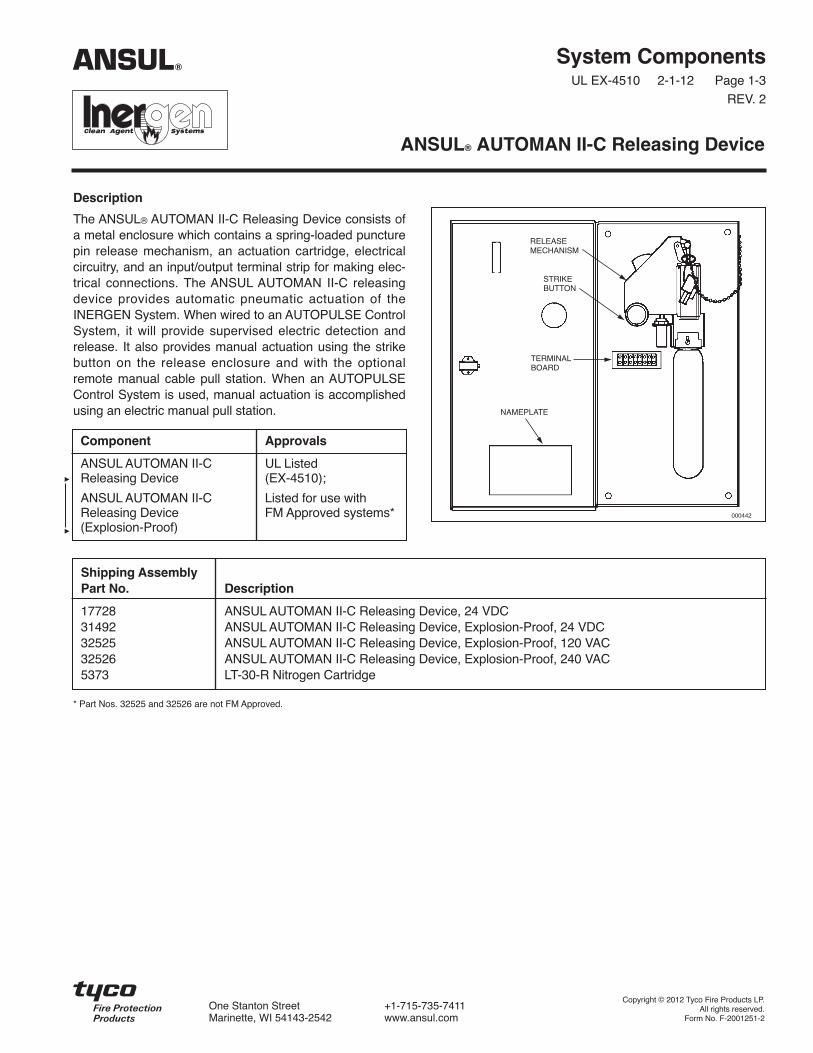
Description
The ANSUL® AUTOMAN II-C Releasing Device consists ofa metal enclosure which contains a spring-loaded puncturepin release mechanism, an actuation cartridge, electricalcircuitry, and an input/output terminal strip for making elec-trical connections. The ANSUL AUTOMAN II-C releasingdevice provides automatic pneumatic actuation of theINERGEN System. When wired to an AUTOPULSE ControlSystem, it will provide supervised electric detection andrelease. It also provides manual actuation using the strikebutton on the release enclosure and with the optionalremote manual cable pull station. When an AUTOPULSEControl System is used, manual actuation is accomplishedusing an electric manual pull station.
ANSUL® AUTOMAN II-C Releasing Device
RELEASEMECHANISM
STRIKEBUTTON
TERMINALBOARD
NAMEPLATE
000442
Component Approvals
ANSUL AUTOMAN II-C UL ListedReleasing Device (EX-4510);
ANSUL AUTOMAN II-C Listed for use withReleasing Device FM Approved systems*(Explosion-Proof)
Shipping AssemblyPart No. Description
17728 ANSUL AUTOMAN II-C Releasing Device, 24 VDC31492 ANSUL AUTOMAN II-C Releasing Device, Explosion-Proof, 24 VDC32525 ANSUL AUTOMAN II-C Releasing Device, Explosion-Proof, 120 VAC32526 ANSUL AUTOMAN II-C Releasing Device, Explosion-Proof, 240 VAC5373 LT-30-R Nitrogen Cartridge
* Part Nos. 32525 and 32526 are not FM Approved.
ANSUL®
Copyright © 2012 Tyco Fire Products LP.All rights reserved.
Form No. F-2001251-2
One Stanton Street +1-715-735-7411Marinette, WI 54143-2542 www.ansul.com


System ComponentsUL EX-4510 2-1-12 Page 1-4
REV. 3
Description
Selector valves are used to direct the flow of INERGEN intoa single hazard of a multiple hazard system.
When pneumatic actuation is required for the 1 in. and 2 in.valves, a Stackable Actuator Assembly, Part No. 428566,must be ordered separately.
When electric actuation is required for the 1 in. and 2 in.valves, a Booster Actuator, Part No. 428949, must beordered separately.
Selector valves can be manually operated by mounting alever actuator either directly onto the valve or onto the topof the electric actuator. See Lever Release ActuatorComponent Sheet for correct actuator.
Selector Valves
Component Material Thread Size/Type ApprovalsEquivalent Length(Sch. 80 Pipe)
1 in. Selector Valve Bronze 1 in. NPT Female UL (EX-4510); 1/2 in. – 1.9 ft (0.6 m)(Used for 1/2 in., 3/4 in. Listed for use with 3/4 in. – 6.4 ft (1.9 m)and 1 in. pipe sizes) FM Approved systems 1 in. – 10.4 ft (3.2 m)
2 in. Selector Valve Bronze 2 in. NPT Female UL (EX-4510); 1 1/4 in. – 16.2 ft (4.9 m)(Used for 1 1/4 in., 1 1/2 in. Listed for use with 1 1/2 in. – 22.4 ft (6.8 m)and 2 in. pipe sizes) FM Approved systems 2 in. – 67.4 ft (20.5 m)
Shipping AssemblyPart No. Description
427185 1 in. selector valve – threaded
427150 2 in. selector valve – threaded
428566 Pressure operatedstackable actuator
ANSUL®
A B CValve Size Body in. (mm) in. (mm) in. (mm)
1 in. Threaded – 5 1/2 (140) 2 9/16 (67) 7 (178)1 in. NPT female
2 in. Threaded – 7 1/2 (191) 3 1/2 (89) 8 9/16 (218)2 in. NPT female
0060351 IN. AND 2 IN. THREADED VALVE
A
B
C
1 1/8 – 18 UNEF
Copyright © 2012 Tyco Fire Products LP.All rights reserved.
Form No. F-2001252-3
One Stanton Street +1-715-735-7411Marinette, WI 54143-2542 www.ansul.com

System ComponentsUL EX-4510 2-1-12 Page 1-5
REV. 2
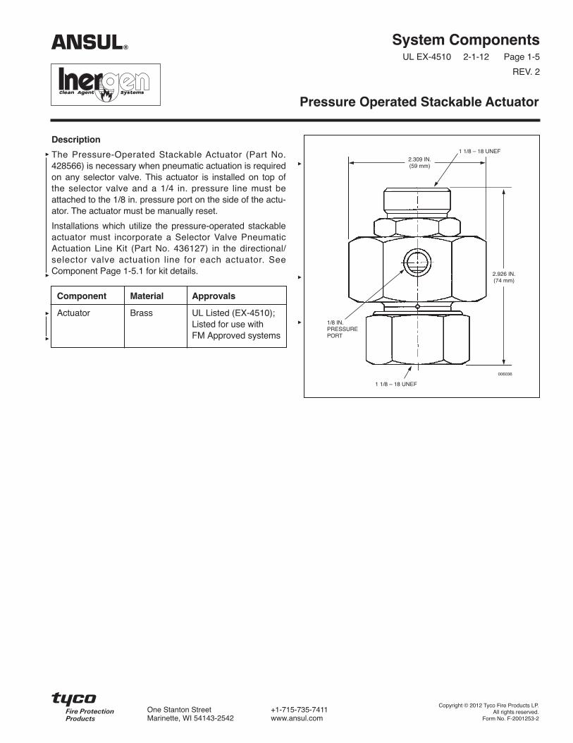
Description
The Pressure-Operated Stackable Actuator (Part No.428566) is necessary when pneumatic actuation is requiredon any selector valve. This actuator is installed on top ofthe selector valve and a 1/4 in. pressure line must beattached to the 1/8 in. pressure port on the side of the actu-ator. The actuator must be manually reset.
Installations which utilize the pressure-operated stackableactuator must incorporate a Selector Valve PneumaticActuation Line Kit (Part No. 436127) in the directional/selector valve actuation line for each actuator. SeeComponent Page 1-5.1 for kit details.
Pressure Operated Stackable Actuator
006036
2.309 IN.(59 mm)
2.926 IN.(74 mm)
1/8 IN.PRESSUREPORT
1 1/8 – 18 UNEF
1 1/8 – 18 UNEF
ANSUL®
Component Material Approvals
Actuator Brass UL Listed (EX-4510);Listed for use withFM Approved systems
Copyright © 2012 Tyco Fire Products LP.All rights reserved.
Form No. F-2001253-2
One Stanton Street +1-715-735-7411Marinette, WI 54143-2542 www.ansul.com


Description
The Selector Valve Pneumatic Actuation Line Kit (Part No.436127) is used to control the pressure in the actuationlines of the selector valves. One selector valve pneumaticactuation line kit is required for each Pneumatic Actuator(Part No. 428566) and must be installed within 1 ft (0.3 m)of the actuator/isolation valve.
The Low Pressure Vent Plug (Part No. 436085) and SafetyRelief Valve (Part No. 15677) are to be installed with atorque of 125 in.-lb (14 N m).
After system discharge, all pressure in the actuation linemust be relieved by pulling the ring on the safety reliefvalve.
System ComponentsUL EX-4510 2-1-12 Page 1-5.1
Selector Valve Pneumatic Actuation Line Kit
008246
ANSUL®
Copyright © 2012 Tyco Fire Products LP.All rights reserved.
Form No. F-2012054
One Stanton Street +1-715-735-7411Marinette, WI 54143-2542 www.ansul.com
Shipping AssemblyPart No. Description
436127 Selector Valve PneumaticActuation Line Kit
436085 Low Pressure Vent Plug15677 Safety Relief Valve28484 1/4 in. Close Nipple27350 1/4 in. Tee
Component Material Approvals
Low-Pressure Brass UL Listed (EX-4510);Vent Plug Listed for use with
FM Approved systems
Safety Relief Brass UL Listed (EX-4510);Valve Listed for use with
FM Approved systems
1/4 in. Close Galvanized UL Listed (EX-4510);Nipple Steel Listed for use with
FM Approved systems
1/4 in. Tee Galvanized UL Listed (EX-4510);Steel Listed for use with
FM Approved systems
Note: The low pressure vent plug cannot be ordered sepa-rately.
4 3/4 IN.(121 mm)
1 3/4 IN.(44 mm)
1/4 IN.TEE
1/4 IN.CLOSENIPPLE
LOW PRESSUREVENT PLUG
SAFETYRELIEFVALVE


Description
The Booster Actuator, Part No. 428949, is used when elec-tric actuation is required on the 1 in. selector valve, 2 in.selector valve, or the CV-98 cylinder valve. The actuatormounts directly to the component and then a HF electricactuator mounts to the top of the booster actuator.
The Booster Actuator requires resetting after actuation. AReset Tool, Part No. 429847, is available for this use.
System ComponentsUL EX-4510 2-1-12 Page 1-6
REV. 2
Booster Actuator
006037
Ø 2.50
3.025
1 1/4 – 18 UNEF
1 1/8 – 18 UNEF
Component Material Approvals
Booster Stainless Steel UL Listed (EX-4510);Actuator and Brass Listed for use with FM
Approved systems
ANSUL®
Copyright © 2012 Tyco Fire Products LP.All rights reserved.
Form No. F-2001254-2
One Stanton Street +1-715-735-7411Marinette, WI 54143-2542 www.ansul.com


4 1/2 IN.(114 mm)
2 1/4 IN.(57 mm)
System ComponentsUL EX-4510 2-1-12 Page 1-7
REV. 2
Description
Electrical actuation is accomplished by an HF electricActuator, Part No. 73327, interfaced through anAUTOPULSE Control System. This actuator can be used inhazardous, indoor environments where the ambient tem-perature range is between 0 °F to 130 °F (–18 °C to 54 °C).The HF electric actuator meets the requirements of N.E.C.Class I, Div. 1, Groups B, C, D and Class II, Div. 1, GroupsE, F, G. A maximum of two HF electric actuators can beused on a single AUTOPULSE release circuit. When utiliz-ing only one HF electric actuator, an in-line resistor, PartNo. 73606, is required in the supervised release circuit.
In auxiliary or override applications, a manual-local overridevalve actuator or a manual cable pull actuator can beinstalled on top of the HF electric actuator by removing thesafety cap.
An arming tool, Part No. 75433, is required to reset theactuator after operation. The actuator contains a standard1/2 in. threaded female straight connector for electrical con-duit hookup.
Technical Information
Nominal Voltage: . . . . . . . . . . . . . . . . 12 VDC @ 0.57 amps
Rated Voltage:Minimum: . . . . . . . . . . . . . . . . . . . . . . . . . . . . . 12.0 VDCMaximum:. . . . . . . . . . . . . . . . . . . . . . . . . . . . . 14.0 VDC
Thread Size/Type: . . . . . . . . . . . . 1/2 in. straight female forelectrical conduit hookup
Material:Body: . . . . . . . . . . . . . . . . . . . . . . . . . . . . . . . . . . . . BrassPlunger:. . . . . . . . . . . . . . . . . . . . . . . . . . . Stainless Steel
Listings and ApprovalsUL. . . . . . . . . . . . . . . . . . . . . . . . . . . . . . . . . . . . . . . E91021
Listed for use with FM Approved systems
HF Electric Actuator
006361
1 1/4 – 18
ANSUL®
1 1/4 – 18
Copyright © 2012 Tyco Fire Products LP.All rights reserved.
Form No. F-2001255-2
One Stanton Street +1-715-735-7411Marinette, WI 54143-2542 www.ansul.com


System ComponentsUL EX-4510 2-1-12 Page 1-8
REV. 3
Description
The manual lever release actuator provides a manualmeans of actuating cylinder valves and selector valves.This can be accomplished by direct manual actuation of itspull lever or cable actuation when used in conjunction witha remote manual pull station. When used with a remotemanual pull station, the pull station must contain the com-ponents necessary to meet the actuator lever travelingrequirements of 7 in. (178 mm).
The actuator is shipped with ring pin and chain attached. Ifthe ring pin is not required, it must be removed. Failure toremove the ring pin/chain assembly will prevent systemactuation if a remote cable pull actuation system isemployed and the ring pin is accidentally installed in theactuator.
Four actuators are available. Each is designed for a specific component.
Lever Release Actuator
Component Material Approvals
All Manual Brass with UL Listed (EX-4510);Cable-pull Stainless Listed for use withActuators Steel Pin FM Approved systems
3 7/8 IN.(9.8 cm)
DEPTH: 3 7/8 IN. (7.6 cm)
3 7/8 IN.*(9.8 cm)
000897
* Add 1 9/16 in. (3.9 cm) to height when lever is in the straight up position.
PIN
ShippingAssemblyPart No. Description
423309 Lever Release (1 1/8-18 mountingthread) – Mounts directly to aCV-98 cylinder valve.
70846 Lever Release (1 1/4-18 mountingthread) – Mounts directly to anHF electric actuator.
427207 Lever Release (1 1/8-18 mountingthread) – Mounts directly to the 1 in.and 2 in. selector valves. Mountsdirectly to pressure operated stackableactuator for 1 in. and 2 in. selectorvalves. Actuator has the handlepainted red.
ANSUL®
Copyright © 2012 Tyco Fire Products LP.All rights reserved.
Form No. F-2001256-3
One Stanton Street +1-715-735-7411Marinette, WI 54143-2542 www.ansul.com

Description
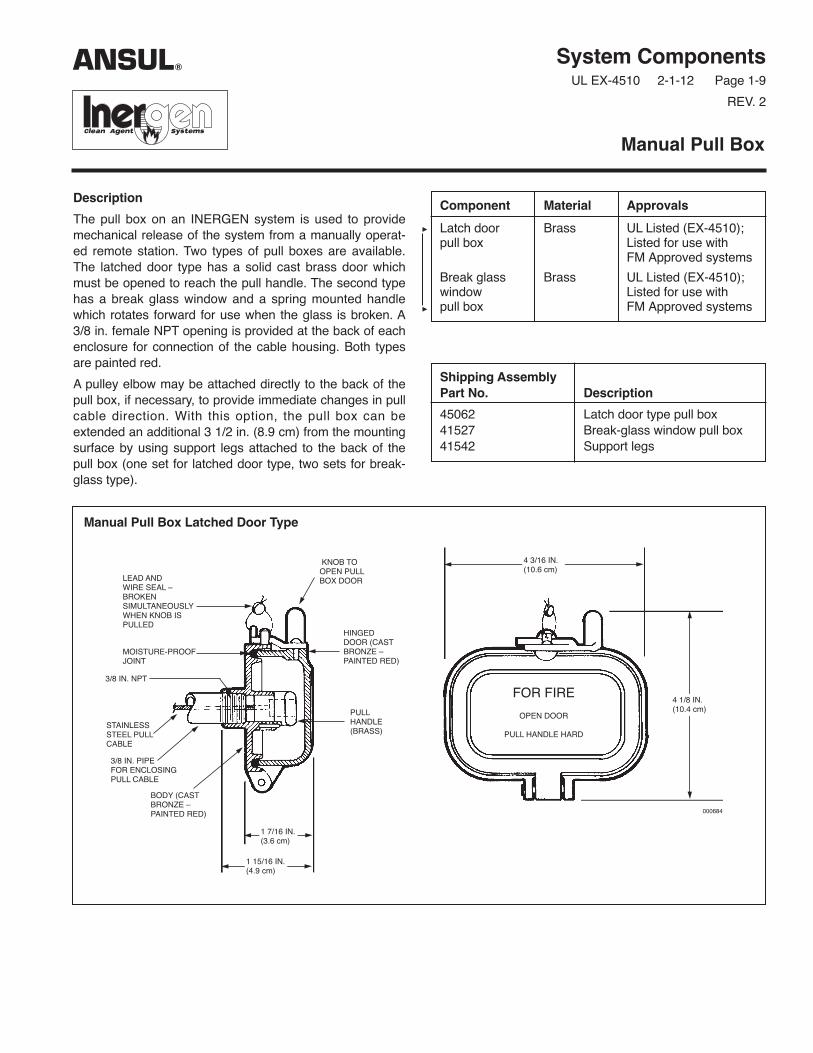
The pull box on an INERGEN system is used to providemechanical release of the system from a manually operat-ed remote station. Two types of pull boxes are available.The latched door type has a solid cast brass door whichmust be opened to reach the pull handle. The second typehas a break glass window and a spring mounted handlewhich rotates forward for use when the glass is broken. A3/8 in. female NPT opening is provided at the back of eachenclosure for connection of the cable housing. Both typesare painted red.
A pulley elbow may be attached directly to the back of thepull box, if necessary, to provide immediate changes in pullcable direction. With this option, the pull box can beextended an additional 3 1/2 in. (8.9 cm) from the mountingsurface by using support legs attached to the back of thepull box (one set for latched door type, two sets for break-glass type).
System ComponentsUL EX-4510 2-1-12 Page 1-9
REV. 2
Manual Pull Box
Component Material Approvals
Latch door Brass UL Listed (EX-4510);pull box Listed for use with
FM Approved systems
Break glass Brass UL Listed (EX-4510);window Listed for use withpull box FM Approved systems
Shipping AssemblyPart No. Description
45062 Latch door type pull box41527 Break-glass window pull box41542 Support legs
Manual Pull Box Latched Door Type
KNOB TOOPEN PULLBOX DOORLEAD AND
WIRE SEAL –BROKENSIMULTANEOUSLYWHEN KNOB ISPULLED
HINGEDDOOR (CASTBRONZE –PAINTED RED)
MOISTURE-PROOFJOINT
3/8 IN. NPT
PULLHANDLE(BRASS)
FOR FIRE
OPEN DOOR
PULL HANDLE HARDSTAINLESSSTEEL PULLCABLE
3/8 IN. PIPEFOR ENCLOSINGPULL CABLE
BODY (CASTBRONZE –PAINTED RED)
1 7/16 IN.(3.6 cm)
1 15/16 IN.(4.9 cm)
4 3/16 IN.(10.6 cm)
4 1/8 IN.(10.4 cm)
ANSUL®
000684

Manual Pull Box Break Glass Type “A”
SPRING FORCESHANDLEOUT INTOOPERATINGPOSITIONWHEN GLASSIS BROKEN
MOISTUREPROOFJOINT
PULLHANDLE
GLASSFRONT
3/8 IN. PIPETO ENCLOSEPULL CABLE
1/16 IN. STAINLESSSTEEL PULL CABLE
CASTBRASSHINGEDCOVER(PAINTEDRED)
CAST BRASSBODY(PAINTED RED)
STOWAGE SPACEFOR SPAREDISCS ANDWASHERS
2 13/16 IN.(7.1 cm)
PROTECTED HAZARDENGRAVED INNAMEPLATE (SPECIFY)
4 7/16 IN.(11.2 cm)
3 1/4 IN.(8.2 cm)
4 – 3/16 IN.MOUNTINGHOLES
4 7/8 IN.(12.3 cm)
3 IN.(7.6 cm)
IN CASE OF FIREBREAK GLASS AND
PULL HANDLE HARDUNTIL RED PAINTMARK ON CABLE
SHOWS
BRASS HAMMERAND CHAINSECUREDTO BOX
Copyright © 2012 Tyco Fire Products LP.All rights reserved.
Form No. F-2001257-2
One Stanton Street +1-715-735-7411Marinette, WI 54143-2542 www.ansul.com
System ComponentsUL EX-4510 2-1-12 Page 1-10
REV. 2
Description
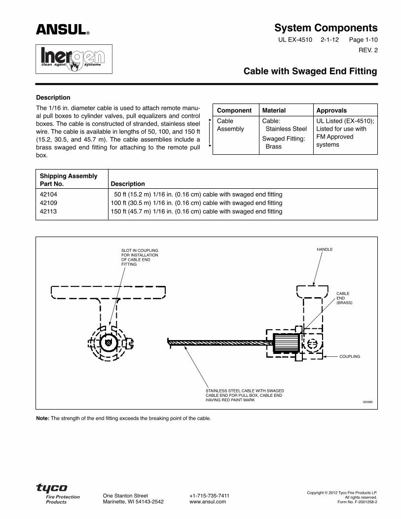
The 1/16 in. diameter cable is used to attach remote manu-al pull boxes to cylinder valves, pull equalizers and controlboxes. The cable is constructed of stranded, stainless steelwire. The cable is available in lengths of 50, 100, and 150 ft(15.2, 30.5, and 45.7 m). The cable assemblies include abrass swaged end fitting for attaching to the remote pullbox.
Cable with Swaged End Fitting
Component Material Approvals
Cable Cable: UL Listed (EX-4510);Assembly Stainless Steel Listed for use with
Swaged Fitting: FM Approved
Brass systems
Shipping AssemblyPart No. Description
42104 50 ft (15.2 m) 1/16 in. (0.16 cm) cable with swaged end fitting42109 100 ft (30.5 m) 1/16 in. (0.16 cm) cable with swaged end fitting42113 150 ft (45.7 m) 1/16 in. (0.16 cm) cable with swaged end fitting
Note: The strength of the end fitting exceeds the breaking point of the cable.
HANDLE
CABLEEND(BRASS)
COUPLING
SLOT IN COUPLINGFOR INSTALLATIONOF CABLE ENDFITTING
STAINLESS STEEL CABLE WITH SWAGEDCABLE END FOR PULL BOX, CABLE ENDHAVING RED PAINT MARK 000689
ANSUL®
Copyright © 2012 Tyco Fire Products LP.All rights reserved.
Form No. F-2001258-2
One Stanton Street +1-715-735-7411Marinette, WI 54143-2542 www.ansul.com

System ComponentsUL EX-4510 2-1-12 Page 1-11
REV. 2
Description
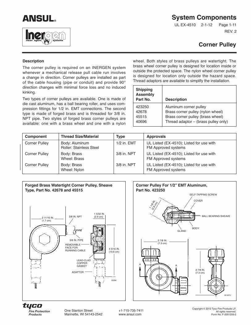
The corner pulley is required on an INERGEN systemwhenever a mechanical release pull cable run involvesa change in direction. Corner pulleys are installed as partof the cable housing (pipe or conduit) and provide 90°direction changes with minimal force loss and no inducedkinking.
Two types of corner pulleys are available. One is made ofdie cast aluminum, has a ball bearing roller, and uses com-pression fittings for 1/2 in. EMT connections. The secondtype is made of forged brass and is threaded for 3/8 in.NPT pipe. Two styles of forged brass corner pulleys areavailable: one with a brass wheel and one with a nylon
wheel. Both styles of brass pulleys are watertight. Thebrass wheel corner pulley is designed for location inside oroutside the protected space. The nylon wheel corner pulleyis designed for location only outside the hazard space.Thread adaptors are available to simplify the installation.
Corner Pulley
Component Thread Size/Material Type Approvals
Corner Pulley Body: Aluminum 1/2 in. EMT UL Listed (EX-4510); Listed for use withRoller: Stainless Steel FM Approved systems
Corner Pulley Body: Brass 3/8 in. NPT UL Listed (EX-4510); Listed for use withWheel: Brass FM Approved systems
Corner Pulley Body: Brass 3/8 in. NPT UL Listed (EX-4510); Listed for use withWheel: Nylon FM Approved systems
ShippingAssemblyPart No. Description
423250 Aluminum corner pulley42678 Brass corner pulley (nylon wheel)45515 Brass corner pulley (brass wheel)40696 Thread adaptor – (brass pulley only)
ANSUL®
Forged Brass Watertight Corner Pulley, SheaveType, Part No. 42678 and 45515
Corner Pulley For 1/2ʼ̓ EMT Aluminum,Part No. 423250
4 3/16 IN.(10.6 cm)
2 11/16 IN.(1.7 cm)
3/8 IN. NPT1 5/32 IN.(2.9 cm)
LEAD-CLADCOPPERGASKET
3/8 IN. PIPE
REMOVABLEFACE FORRUNNING CABLE
ADAPTOR
00690
1 1/
8 IN
.(2
.8 c
m)
GLANDBODY
COVER
SELF-TAPPING SCREW
BALL BEARING SHEAVE
2 7/8 IN.(7.3 cm)
2 7/8 IN.(7.3 cm)
001815
A A
Copyright © 2012 Tyco Fire Products LP.All rights reserved.
Form No. F-2001259-2
One Stanton Street +1-715-735-7411Marinette, WI 54143-2542 www.ansul.com


System ComponentsUL EX-4510 2-1-12 Page 1-12
REV. 2
Description
The dual/triple control boxes allow manual actuation of acylinder valve from two or three remote pull stations. Twostyles of control boxes are available. Part No. 42784 is13 3/4 in. (34.9 cm) and Part No. 43166 is 20 3/4 in.(52.7 cm) long. Both styles can be used for cylinder valveactuation. The inlet and outlet connections are threaded for3/8 in. pipe. If 1/2 in. EMT conduit connections arerequired, adaptor Part No. 45780 is available.
Dual/Triple Control Boxes
Shipping AssemblyPart No. Description
42784 Dual/triple control box (short)43166 Dual/triple control box (long)
Component Material Thread Size/Type Approvals
Control Box (short) Steel 3/8 in. NPT Female UL Listed (EX-4510); Listed for use withFM Approved systems
Control Box (long) Steel 3/8 in. NPT Female UL Listed (EX-4510); Listed for use withFM Approved systems
Part No. 42784 Junction Box(Shown Without Cover)
End View
5/8 IN.(1.5 cm)
3 1/4 IN.(8.2 cm)
1/2 IN.(1.2 cm)
2 3/4 IN.(6.9 cm)
1 7/8 IN.(4.7 cm)
11/16 IN.(1.7 cm)
REMOVABLE COVER
1 IN.(2.5 cm)
12 1/4 IN.(31.1 cm)
13 3/4 IN. (34.9 cm)(OVERALL)
DIRECTION OF PULL
CABLE-PULL FROMPULL-BOXESFLEXIBLE TRANSPARENT
PROTECTION RING
CABLE CLAMPCABLE – PULL TOCYLINDER RELEASE
3/8 IN. PIPE OR1/2 IN. E.M.T.*
4 – 9/32 IN. (0.71 cm)MOUNTING HOLES
CLAMP WITHINBLACK AREA
ANSUL®
Part No. 43166 Junction Box(Shown Without Cover)
End View
5/8 IN.(1.5 cm)
3 1/4 IN.(8.2 cm)
1/2 IN.(1.2 cm)
2 3/4 IN.(6.9 cm)
1 7/8 IN.(4.7 cm)
11/16 IN.(1.7 cm)
REMOVABLE COVER
1 IN.(2.5 cm)
19 1/4 IN.(48.8 cm)
20 3/4 IN.(52.7 cm)
DIRECTION OF PULL
CABLE-PULL FROMPULL-BOXESFLEXIBLE TRANSPARENT
PROTECTION RING
CABLE CLAMPCABLE – PULL TOCYLINDER RELEASE
3/8 IN. PIPE OR1/2 IN. E.M.T.*
4 – 9/32 IN. (0.71 cm)MOUNTING HOLES
CLAMP WITHINBLACK AREA
* Adaptors furnished for use with 1/2 in. EMT – Part No. 45780
000685
000685
Copyright © 2012 Tyco Fire Products LP.All rights reserved.
Form No. F-2001260-2
One Stanton Street +1-715-735-7411Marinette, WI 54143-2542 www.ansul.com

System ComponentsUL EX-4510 2-1-12 Page 1-13
REV. 2
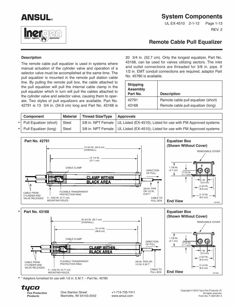
Description
The remote cable pull equalizer is used in systems wheremanual actuation of the cylinder valve and operation of aselector valve must be accomplished at the same time. Thepull equalizer is mounted in the remote pull station cableline. By pulling the remote pull box, the cable attached tothe pull equalizer will pull the internal cable clamp in thepull equalizer which in turn will pull the cables attached tothe cylinder valve and selector valve, causing them to oper-ate. Two styles of pull equalizers are available. Part No.42791 is 13 3/4 in. (34.9 cm) long and Part No. 43168 is
20 3/4 in. (52.7 cm). Only the longest equalizer, Part No.43168, can be used for valves utilizing sectors. The inletand outlet connections are threaded for 3/8 in. pipe. If1/2 in. EMT conduit connections are required, adaptor PartNo. 45780 is available.
Remote Cable Pull Equalizer
ShippingAssemblyPart No. Description
42791 Remote cable pull equalizer (short)
43168 Remote cable pull equalizer (long)
Part No. 42791 Equalizer Box(Shown Without Cover)
End View
3 1/4 IN.(8.2 cm)
2 3/4 IN.(6.9 cm)
1 7/8 IN.(4.7 cm)
11/16 IN.(1.7 cm)
REMOVABLE COVER
1 IN.(2.5 cm)
12 1/4 IN.(31.1 cm)
13 3/4 IN. (34.9 cm)(OVERALL)
DIRECTIONOF PULL
FLEXIBLE TRANSPARENTPROTECTION RING
CABLE CLAMP
CABLE FROMCYLINDER ANDVALVE RELEASES 4 – 9/32 IN. (0.71 cm)
MOUNTING HOLES
3/8 IN. PIPEOR 1/2 IN.E.M.T.*
ANSUL®
Component Material Thread Size/Type Approvals
Pull Equalizer (short) Steel 3/8 in. NPT Female UL Listed (EX-4510); Listed for use with FM Approved systems
Pull Equalizer (long) Steel 3/8 in. NPT Female UL Listed (EX-4510); Listed for use with FM Approved systems
001844
Part No. 43168 Equalizer Box(Shown Without Cover)
End View
3 1/4 IN.(8.2 cm)
2 3/4 IN.(6.9 cm)
1 7/8 IN.(4.7 cm)
11/16 IN.(1.7 cm)
REMOVABLE COVER
1 IN.(2.5 cm)
19 1/4 IN.(48.8 cm)
20 3/4 IN. (52.7 cm)(OVERALL)
DIRECTIONOF PULL
CABLE TO PULL BOX
FLEXIBLE TRANSPARENTPROTECTION RING
CABLE CLAMP
CABLE FROMCYLINDER ANDVALVE RELEASES
4 – 9/32 IN. (0.71 cm)MOUNTING HOLES
3/8 IN. PIPE OR1/2 IN. E.M.T.*
* Adaptors furnished for use with 1/2 in. E.M.T. – Part No. 45780
001844
CABLE TO PULL BOX
Copyright © 2012 Tyco Fire Products LP.All rights reserved.
Form No. F-2001261-2
One Stanton Street +1-715-735-7411Marinette, WI 54143-2542 www.ansul.com

System ComponentsUL EX-4510 2-1-12 Page 1-14
REV. 2
Description
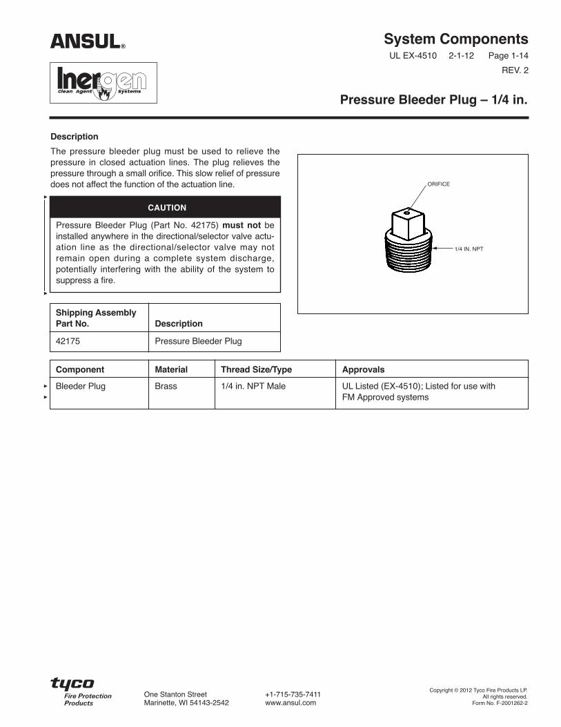
The pressure bleeder plug must be used to relieve thepressure in closed actuation lines. The plug relieves thepressure through a small orifice. This slow relief of pressuredoes not affect the function of the actuation line.
Pressure Bleeder Plug – 1/4 in.
Component Material Thread Size/Type Approvals
Bleeder Plug Brass 1/4 in. NPT Male UL Listed (EX-4510); Listed for use withFM Approved systems
Shipping AssemblyPart No. Description
42175 Pressure Bleeder Plug
ORIFICE
1/4 IN. NPT
ANSUL®
Copyright © 2012 Tyco Fire Products LP.All rights reserved.
Form No. F-2001262-2
One Stanton Street +1-715-735-7411Marinette, WI 54143-2542 www.ansul.com
CAUTION
Pressure Bleeder Plug (Part No. 42175) must not beinstalled anywhere in the directional/selector valve actu-ation line as the directional/selector valve may notremain open during a complete system discharge,potentially interfering with the ability of the system tosuppress a fire.

System ComponentsUL EX-4510 2-1-12 Page 1-15
REV. 2
Description
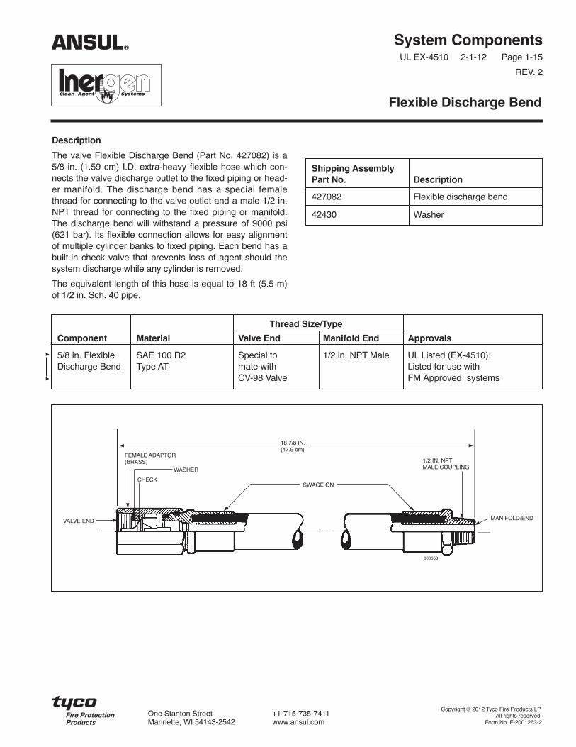
The valve Flexible Discharge Bend (Part No. 427082) is a5/8 in. (1.59 cm) I.D. extra-heavy flexible hose which con-nects the valve discharge outlet to the fixed piping or head-er manifold. The discharge bend has a special femalethread for connecting to the valve outlet and a male 1/2 in.NPT thread for connecting to the fixed piping or manifold.The discharge bend will withstand a pressure of 9000 psi(621 bar). Its flexible connection allows for easy alignmentof multiple cylinder banks to fixed piping. Each bend has abuilt-in check valve that prevents loss of agent should thesystem discharge while any cylinder is removed.
The equivalent length of this hose is equal to 18 ft (5.5 m)of 1/2 in. Sch. 40 pipe.
Flexible Discharge Bend
Shipping AssemblyPart No. Description
427082 Flexible discharge bend
42430 Washer
Thread Size/Type
Component Material Valve End Manifold End Approvals
5/8 in. Flexible SAE 100 R2 Special to 1/2 in. NPT Male UL Listed (EX-4510);Discharge Bend Type AT mate with Listed for use with
CV-98 Valve FM Approved systems
18 7/8 IN.(47.9 cm)
MANIFOLD/END
000658
1/2 IN. NPTMALE COUPLING
FEMALE ADAPTOR(BRASS)
VALVE END
CHECK
WASHER
SWAGE ON
ANSUL®
Copyright © 2012 Tyco Fire Products LP.All rights reserved.
Form No. F-2001263-2
One Stanton Street +1-715-735-7411Marinette, WI 54143-2542 www.ansul.com


System ComponentsUL EX-4510 2-1-12 Page 1-16
REV. 2
Description
Check valves are used in main/reserve and selector valvesystems. On main/reserve systems, the check valve pre-vents pressurization of the reserve system manifold byblocking the flow of INERGEN agent from the main systemto the reserve system. The check valve allows gas flowfrom the reserve (if actuated) to pass through into the distri-bution piping. On selector valve systems, check valves separate the actuation of smaller system(s) from the largestones.
The check valves are available in sizes from 1/2 in. through3 in.
Check Valves
Shipping AssemblyPart No. Description
40860 1/2 in. check valve*40852 3/4 in. check valve41470 1 in. check valve41549 1 1/4 in. check valve41463 1 1/2 in. check valve40649 2 in. check valve40656 2 1/2 in. check valve40665 3 in. check valve
Component Material Thread Size/Type Body Type ApprovalsEquivalent Length(Sch. 80 Pipe)
Check Valve Bronze 1/2-14 NPT Female Threaded UL Listed (EX-4510) 12. 0 ft (3.7 m)
Check Valve Bronze 3/4-14 NPT Female Threaded UL Listed (EX-4510); 24.0 ft (7.3 m)Listed for use withFM Approved systems
Check Valve Bronze 1-11 1/2 NPT Female Threaded UL Listed (EX-4510); 28.0 ft (8.5 m)Listed for use withFM Approved systems
Check Valve Bronze 1 1/4 -11 1/2 NPT Female Threaded UL Listed (EX-4510); 43.0 ft (13.1 m)Listed for use withFM Approved systems
Check Valve Bronze 1 1/2-11 1/2 NPT Female Threaded UL Listed (EX-4510); 51.0 ft (15.5 m)Listed for use withFM Approved systems
Check Valve Bronze 2-11 1/2 NPT Female Threaded UL Listed (EX-4510); 48.0 ft (14.6 m)Listed for use withFM Approved systems
Check Valve Bronze 2 1/2-8 NPT Female Threaded UL Listed (EX-4510); 60.0 ft (18.3 m)Listed for use withFM Approved systems
Check Valve Bronze Body 3-8 NPT Female Threaded UL Listed (EX-4510); 154.0 ft (46.9 m)Steel Flange Flange Listed for use with
FM Approved systems
ANSUL®
* If an FM Approved 1/2 in. Check Valve is required, use a 3/4 in. and reduce the inlet and outlet to 1/2 in.
Note: For FM Approved systems, each FM Approved check valve, after discharge, must be disassembled, inspected for corrosionand wear, replace gasket and parts as necessary, and reassembled. For 2, 2 1/2, and 3 in. valves, see Section VI,Installation, for appropriate flanged bolt torque specifications.
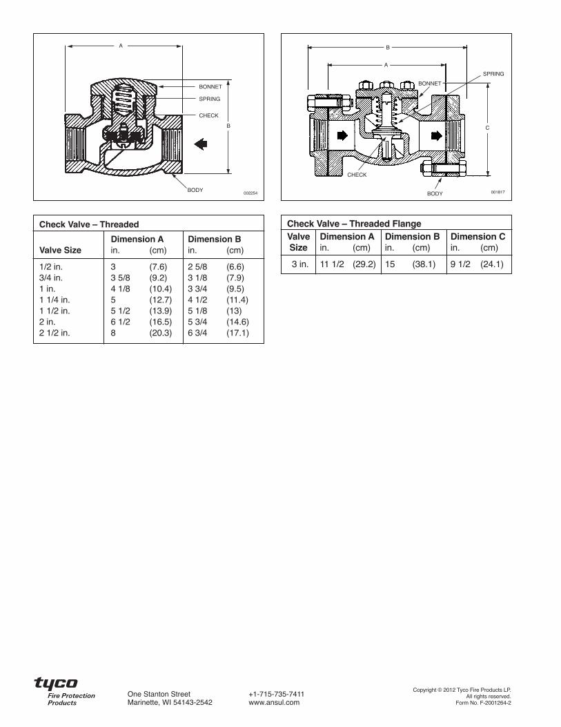
Check Valve – Threaded
Dimension A Dimension BValve Size in. (cm) in. (cm)
1/2 in. 3 (7.6) 2 5/8 (6.6)3/4 in. 3 5/8 (9.2) 3 1/8 (7.9)1 in. 4 1/8 (10.4) 3 3/4 (9.5)1 1/4 in. 5 (12.7) 4 1/2 (11.4)1 1/2 in. 5 1/2 (13.9) 5 1/8 (13)2 in. 6 1/2 (16.5) 5 3/4 (14.6)2 1/2 in. 8 (20.3) 6 3/4 (17.1)
Check Valve – Threaded FlangeValve Dimension A Dimension B Dimension CSize in. (cm) in. (cm) in. (cm)
3 in. 11 1/2 (29.2) 15 (38.1) 9 1/2 (24.1)
A
B
BONNET
BODY
SPRING
CHECK
A
C
B
CHECK
BODY
BONNET
SPRING
001817002254
Copyright © 2012 Tyco Fire Products LP.All rights reserved.
Form No. F-2001264-2
One Stanton Street +1-715-735-7411Marinette, WI 54143-2542 www.ansul.com

Description
The header vent plug is used to release low pressure build-up that may occur in a closed system utilizing selectorvalves or check valves. The header vent plug should alsobe installed on the cylinder sides of the check valves onboth main and reserve systems to relieve any pressure thatmay leak past the check valve and accidentally actuate thereserve system while the main system is discharging.
System ComponentsUL EX-4510 2-1-12 Page 1-17
REV. 2
Header Vent Plug
Shipping AssemblyPart No. Description
40309 Header vent plug
Component Material Thread Size/Type Approvals
Vent Plug Body: 1/2 in. NPT Male UL Listed (EX-4510); Listed for useBrass with FM Approved systems
Spring:Bronze
Seal:Neoprene
SPRING
CHECK SEAL
CHECK CUP
1/2 IN. NPT
000707
STEM
BODY
WASHER
29/32 IN.(2.3 cm)7/8 IN.
(2.2 cm)
ANSUL®
Copyright © 2012 Tyco Fire Products LP.All rights reserved.
Form No. F-2001265-2
One Stanton Street +1-715-735-7411Marinette, WI 54143-2542 www.ansul.com
CAUTION
A header vent plug must be installed in all closed sec-tions of the system manifold(s). The omission of a head-er vent plug may cause the manifold to build pressure.This could result in the actuation of a system cylinder,which would then cause all cylinders in that specific sys-tem to actuate.

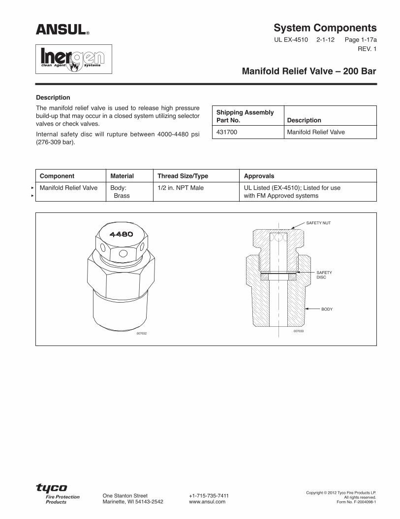
Description
The manifold relief valve is used to release high pressurebuild-up that may occur in a closed system utilizing selectorvalves or check valves.
Internal safety disc will rupture between 4000-4480 psi(276-309 bar).
System ComponentsUL EX-4510 2-1-12 Page 1-17a
REV. 1
Manifold Relief Valve – 200 Bar
Shipping AssemblyPart No. Description
431700 Manifold Relief Valve
Component Material Thread Size/Type Approvals
Manifold Relief Valve Body: 1/2 in. NPT Male UL Listed (EX-4510); Listed for useBrass with FM Approved systems
BODY
SAFETYDISC
SAFETY NUT
007032007033
ANSUL®
Copyright © 2012 Tyco Fire Products LP.All rights reserved.
Form No. F-2004098-1
One Stanton Street +1-715-735-7411Marinette, WI 54143-2542 www.ansul.com


System ComponentsUL EX-4510 2-1-12 Page 1-18
REV. 2
Description
The Stainless Steel Actuation Hose is used to connect theactuation line flared tees between each agent tank. Thehose has the same thread, 7/16-20, as the flared tees. Theactuation hose allows flexibility between the rigid actuationpiping and the tank valve.
Additional actuation fittings are available:
Part No. Description_______ _________
31810 Male Elbow (7/16-20 x 1/4 in. NPT)31811 Male Tee (7/16-20 x 7/16-20 x 1/4 in. NPT)32338 Male Straight Connector (7/16-20 x 1/4 in. NPT)
Stainless Steel Actuation Hose
Shipping AssemblyPart No. Description
31809 16 in. (40.6 cm) StainlessSteel Hose
32335 20 in. (50.8 cm) StainlessSteel Hose
32336 24 in. (60.9 cm) StainlessSteel Hose
Component Material Thread Size Approvals
Stainless Steel Hose Stainless Steel Female 7/16-20 UL Listed (EX-4510); Listed for use(Both ends) with FM Approved systems
24 IN.(61 cm)
7/16-20
000433
7/16-20
ANSUL®
Copyright © 2012 Tyco Fire Products LP.All rights reserved.
Form No. F-2001266-2
One Stanton Street +1-715-735-7411Marinette, WI 54143-2542 www.ansul.com


System ComponentsUL EX-4510 2-1-12 Page 1-19
REV. 2
Description
The pressure reducer/union is required to restrict the flowof INERGEN agent thus reducing the agent pressure downstream of the union. The 3000 psi (206.9 bar) NSCWPunion contains a stainless steel orifice plate which is drilledto the specific size hole required based on the flow calcula-tion.* The orifice plate provides readily visible orifice identi-fication. The orifice union is available in six sizes:1/2 in., 3/4 in., 1 in., 1 1/4 in., 1 1/2 in., and 2 in. NPT.
All pressure reducer/unions must be installed in the pipingwith the orifice identification tab on the pressure inlet sideof the system. The 1 1/4 in., 1 1/2 in. and 2 in. orificeunions must be installed per the direction of the flow arrowstamped on the body.
Pressure Reducer/Union
Shipping AssemblyPart No. Description A B C
416677 1/2 in. NPT pressure reducer/union 2.06 in. (5.2 cm) 1.18 in. (2.9 cm) 1.95 in. (4.9 cm)416678 3/4 in. NPT pressure reducer/union 2.38 in. (6.1 cm) 1.50 in. (3.8 cm) 2.38 in. (6.1 cm)416679 1 in. NPT pressure reducer/union 2.63 in. (6.7 cm) 1.78 in. (4.5 cm) 2.77 in. (7.0 cm)416680 1 1/4 in. NPT pressure reducer/union 2.94 in. (7.5 cm) 2.04 in. (5.2 cm) 3.31 in. (8.4 cm)416681 1 1/2 in. NPT pressure reducer/union 3.31 in. (8.4 cm) 2.31 in. (5.9 cm) 3.70 in. (9.4 cm)416682 2 in. NPT pressure reducer/union 3.56 in. (9.0 cm) 2.85 in. (7.2 cm) 4.39 in. (11.2 cm)
Component Material Thread Size Approvals
Pressure Reducer/ Body: Forged 1/2, 3/4, 1, UL Listed (EX-4510); Listed for useUnion Steel 1 1/4, 1 1/2, with FM Approved systems
2 in. NPTOrifice Plate:
StainlessSteel
VISIBLE ORIFICEIDENTIFICATION 002197
DIRECTIONOF FLOW
C
A
B
Note: Refer to “Nozzle/Pressure Reducer Range Chart” inDesign Section for detailed orifice range information.
* Orifice diameter must be specified when placing order.
ANSUL®
Copyright © 2012 Tyco Fire Products LP.All rights reserved.
Form No. F-2001267-2
One Stanton Street +1-715-735-7411Marinette, WI 54143-2542 www.ansul.com

System ComponentsUL EX-4510 2-1-12 Page 1-19a
REV. 1
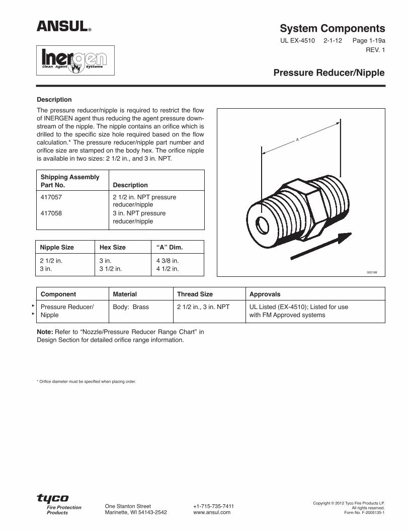
Description
The pressure reducer/nipple is required to restrict the flowof INERGEN agent thus reducing the agent pressure down-stream of the nipple. The nipple contains an orifice which isdrilled to the specific size hole required based on the flowcalculation.* The pressure reducer/nipple part number andorifice size are stamped on the body hex. The orifice nippleis available in two sizes: 2 1/2 in., and 3 in. NPT.
Note: Refer to “Nozzle/Pressure Reducer Range Chart” inDesign Section for detailed orifice range information.
* Orifice diameter must be specified when placing order.
Pressure Reducer/Nipple
Shipping AssemblyPart No. Description
417057 2 1/2 in. NPT pressurereducer/nipple
417058 3 in. NPT pressurereducer/nipple
Nipple Size Hex Size “A” Dim.
2 1/2 in. 3 in. 4 3/8 in.3 in. 3 1/2 in. 4 1/2 in.
Component Material Thread Size Approvals
Pressure Reducer/ Body: Brass 2 1/2 in., 3 in. NPT UL Listed (EX-4510); Listed for useNipple with FM Approved systems
A
002198
ANSUL®
Copyright © 2012 Tyco Fire Products LP.All rights reserved.
Form No. F-2005135-1
One Stanton Street +1-715-735-7411Marinette, WI 54143-2542 www.ansul.com

System ComponentsUL EX-4510 12-1-01 Page 1-20
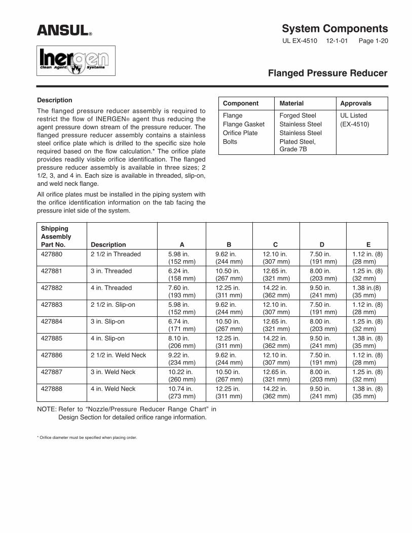
Description
The flanged pressure reducer assembly is required torestrict the flow of INERGEN® agent thus reducing theagent pressure down stream of the pressure reducer. Theflanged pressure reducer assembly contains a stainlesssteel orifice plate which is drilled to the specific size holerequired based on the flow calculation.* The orifice plateprovides readily visible orifice identification. The flangedpressure reducer assembly is available in three sizes; 21/2, 3, and 4 in. Each size is available in threaded, slip-on,and weld neck flange.
All orifice plates must be installed in the piping system withthe orifice identification information on the tab facing thepressure inlet side of the system.
Flanged Pressure Reducer
ShippingAssemblyPart No. Description A B C D E427880 2 1/2 in Threaded 5.98 in. 9.62 in. 12.10 in. 7.50 in. 1.12 in. (8)
(152 mm) (244 mm) (307 mm) (191 mm) (28 mm)
427881 3 in. Threaded 6.24 in. 10.50 in. 12.65 in. 8.00 in. 1.25 in. (8)(158 mm) (267 mm) (321 mm) (203 mm) (32 mm)
427882 4 in. Threaded 7.60 in. 12.25 in. 14.22 in. 9.50 in. 1.38 in.(8)(193 mm) (311 mm) (362 mm) (241 mm) (35 mm)
427883 2 1/2 in. Slip-on 5.98 in. 9.62 in. 12.10 in. 7.50 in. 1.12 in. (8)(152 mm) (244 mm) (307 mm) (191 mm) (28 mm)
427884 3 in. Slip-on 6.74 in. 10.50 in. 12.65 in. 8.00 in. 1.25 in. (8)(171 mm) (267 mm) (321 mm) (203 mm) (32 mm)
427885 4 in. Slip-on 8.10 in. 12.25 in. 14.22 in. 9.50 in. 1.38 in. (8)(206 mm) (311 mm) (362 mm) (241 mm) (35 mm)
427886 2 1/2 in. Weld Neck 9.22 in. 9.62 in. 12.10 in. 7.50 in. 1.12 in. (8)(234 mm) (244 mm) (307 mm) (191 mm) (28 mm)
427887 3 in. Weld Neck 10.22 in. 10.50 in. 12.65 in. 8.00 in. 1.25 in. (8)(260 mm) (267 mm) (321 mm) (203 mm) (32 mm)
427888 4 in. Weld Neck 10.74 in. 12.25 in. 14.22 in. 9.50 in. 1.38 in. (8)(273 mm) (311 mm) (362 mm) (241 mm) (35 mm)
Component Material Approvals
Flange Forged Steel UL ListedFlange Gasket Stainless Steel (EX-4510)Orifice Plate Stainless SteelBolts Plated Steel,
Grade 7B
NOTE: Refer to “Nozzle/Pressure Reducer Range Chart” inDesign Section for detailed orifice range information.
* Orifice diameter must be specified when placing order.
ANSUL®

TYCO SAFETY PRODUCTS, MARINETTE, WI 54143-2542 715-735-7411 Form No. F-2001269 ©2001 Ansul Incorporated
Threaded
A
003655
Slip-On
A
003656
Weld Neck
A
003653
C
B003654
D
E
ANSUL and INERGEN are trademarks of Ansul Incorporated or its affiliates.
System ComponentsUL EX-4510 2-1-12 Page 1-21
REV. 2
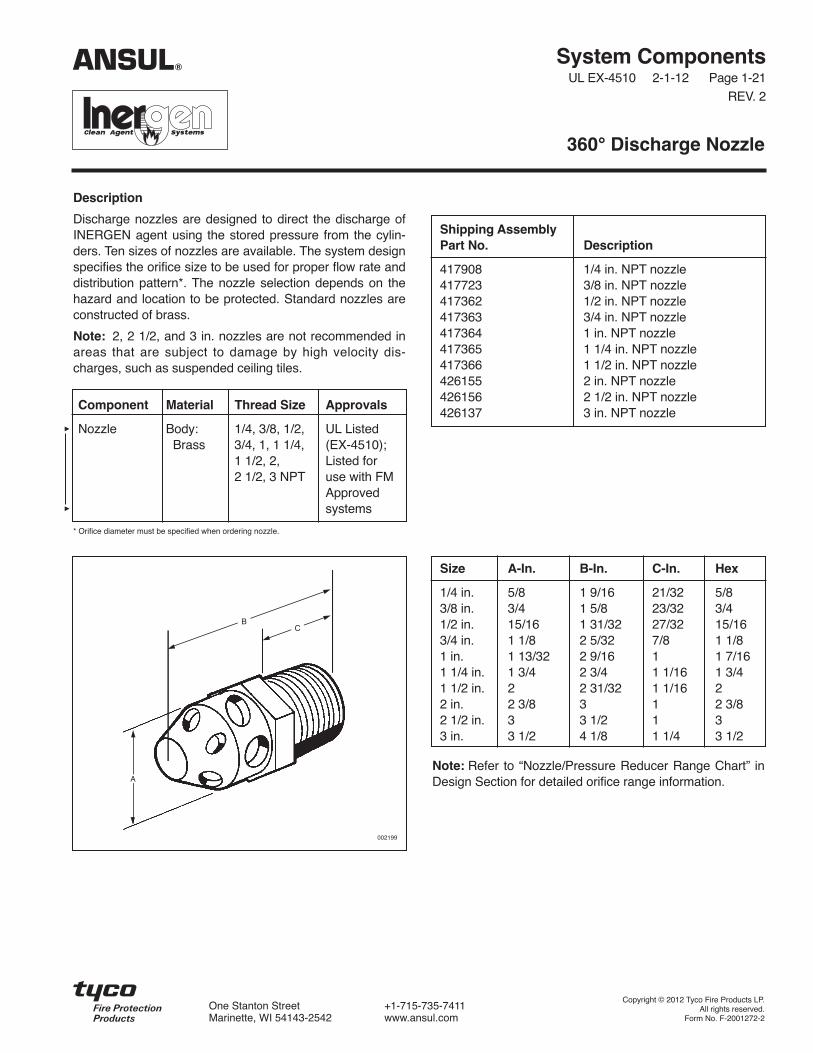
Description
Discharge nozzles are designed to direct the discharge ofINERGEN agent using the stored pressure from the cylin-ders. Ten sizes of nozzles are available. The system designspecifies the orifice size to be used for proper flow rate anddistribution pattern*. The nozzle selection depends on thehazard and location to be protected. Standard nozzles areconstructed of brass.
Note: 2, 2 1/2, and 3 in. nozzles are not recommended inareas that are subject to damage by high velocity dis-charges, such as suspended ceiling tiles.
* Orifice diameter must be specified when ordering nozzle.
360° Discharge Nozzle
Shipping AssemblyPart No. Description
417908 1/4 in. NPT nozzle417723 3/8 in. NPT nozzle417362 1/2 in. NPT nozzle417363 3/4 in. NPT nozzle417364 1 in. NPT nozzle417365 1 1/4 in. NPT nozzle417366 1 1/2 in. NPT nozzle426155 2 in. NPT nozzle426156 2 1/2 in. NPT nozzle426137 3 in. NPT nozzle
Size A-In. B-In. C-In. Hex
1/4 in. 5/8 1 9/16 21/32 5/83/8 in. 3/4 1 5/8 23/32 3/41/2 in. 15/16 1 31/32 27/32 15/163/4 in. 1 1/8 2 5/32 7/8 1 1/81 in. 1 13/32 2 9/16 1 1 7/161 1/4 in. 1 3/4 2 3/4 1 1/16 1 3/41 1/2 in. 2 2 31/32 1 1/16 22 in. 2 3/8 3 1 2 3/82 1/2 in. 3 3 1/2 1 33 in. 3 1/2 4 1/8 1 1/4 3 1/2
BC
A
002199
Note: Refer to “Nozzle/Pressure Reducer Range Chart” inDesign Section for detailed orifice range information.
ANSUL®
Component Material Thread Size Approvals
Nozzle Body: 1/4, 3/8, 1/2, UL ListedBrass 3/4, 1, 1 1/4, (EX-4510);
1 1/2, 2, Listed for 2 1/2, 3 NPT use with FM
Approvedsystems
Copyright © 2012 Tyco Fire Products LP.All rights reserved.
Form No. F-2001272-2
One Stanton Street +1-715-735-7411Marinette, WI 54143-2542 www.ansul.com


System ComponentsUL EX-4510 2-1-12 Page 1-22
REV. 2
Description
Discharge nozzles are designed to direct the discharge ofINERGEN agent using the stored pressure from the cylin-ders. Ten sizes of nozzles are available. The systemdesign specifies the orifice size to be used for proper flowrate and distribution pattern*. The nozzle selectiondepends on the hazard and location to be protected. The180° nozzle is commonly used when nozzle placement isat the wall. Standard nozzles are constructed of brass.
An index mark is stamped on the bottom of the nozzle toindicate the aiming direction.
180° Discharge Nozzle
Shipping AssemblyPart No. Description
426138 1/4 in. NPT nozzle426139 3/8 in. NPT nozzle426140 1/2 in. NPT nozzle426141 3/4 in. NPT nozzle426142 1 in. NPT nozzle426143 1 1/4 in. NPT nozzle426157 1 1/2 in. NPT nozzle426144 2 in. NPT nozzle426145 2 1/2 in. NPT nozzle426146 3 in. NPT nozzle
C
002742
002743
Component Material Thread Size Approvals
Nozzle Body: 1/4, 3/8, 1/2, UL ListedBrass 3/4, 1, 1 1/4, (EX-4510);
1 1/2, 2, 2 1/2, Listed for use3 NPT with FM
Approvedsystems
Size A-In. B-In. C-In.
1/4 in. 5/8 1 9/16 21/323/8 in. 3/4 1 5/8 23/321/2 in. 15/16 1 31/32 27/323/4 in. 1 1/8 2 5/32 7/81 in. 1 13/32 2 9/16 11 1/4 in. 1 3/4 2 3/4 1 1/161 1/2 in. 2 2 31/32 1 1/162 in. 2 3/8 3 12 1/2 in. 3 3 1/2 13 in. 3 1/2 4 1/8 1 1/4
22.5%
A
B
INDEXMARK
Note: Refer to “Nozzle/Pressure Reducer Range Chart” inDesign Section for detailed orifice range information.
ANSUL®
* Orifice diameter must be specified when ordering nozzle.
Copyright © 2012 Tyco Fire Products LP.All rights reserved.
Form No. F-2001273-2
One Stanton Street +1-715-735-7411Marinette, WI 54143-2542 www.ansul.com


System ComponentsUL EX-4510 2-1-12 Page 1-23
REV. 2
Description
The INERGEN system nozzle deflector shield is used tocontrol the pattern of the discharge of the INERGEN agent.The deflector shield helps keep the agent discharge awayfrom false ceiling tiles and fragile light fixtures, avoidingdamage to them.
The deflector shields are constructed of steel and paintedwith a cameo cream colored paint. They are available infive sizes.
Nozzle Deflector Shield
Component Material Approvals
Nozzle Steel UL Listed (EX-4510);Deflector Listed for use withShield FM Approved systems
Shipping A B C D EAssembly Inlet Length of Overall Deflector CouplingPart No. NPT Coupling Length O.D. O.D.
417708 1/2 in. 1 7/8 in. 3 in. 3 3/8 in. 1 1/8 in.(4.8 cm) (7.6 cm) (8.6 cm) (2.9 cm)
417711 3/4 in. 2 in. 3 1/4 in. 3 3/8 in. 1 3/8 in.(5.1 cm) (8.3 cm) (8.6 cm) (3.5 cm)
417714 1 in. 2 3/8 in. 3 13/16 in. 4 7/8 in. 1 3/4 in.(6.0 cm) (9.7 cm) (12.4 cm) (4.4 cm)
417717 1 1/4 in. 2 5/8 in. 4 3/16 in. 4 7/8 in. 2 1/4 in.(6.7 cm) (10.6 cm) (12.4 cm) (5.7 cm)
417720 1 1/2 in. 3 1/8 in. 4 29/32 in. 5 21/32 in. 2 1/2 in.(7.9 cm) (12.5 cm) (14.4 cm) (6.4 cm)
D
B
A
C
E
003651
NOTE: There are no deflector shields available for the 2, 2 1/2, or 3 in. models.
ANSUL®
Copyright © 2012 Tyco Fire Products LP.All rights reserved.
Form No. F-2001274-2
One Stanton Street +1-715-735-7411Marinette, WI 54143-2542 www.ansul.com

System ComponentsUL EX-4510 2-1-12 Page 1-24
REV. 3
Description
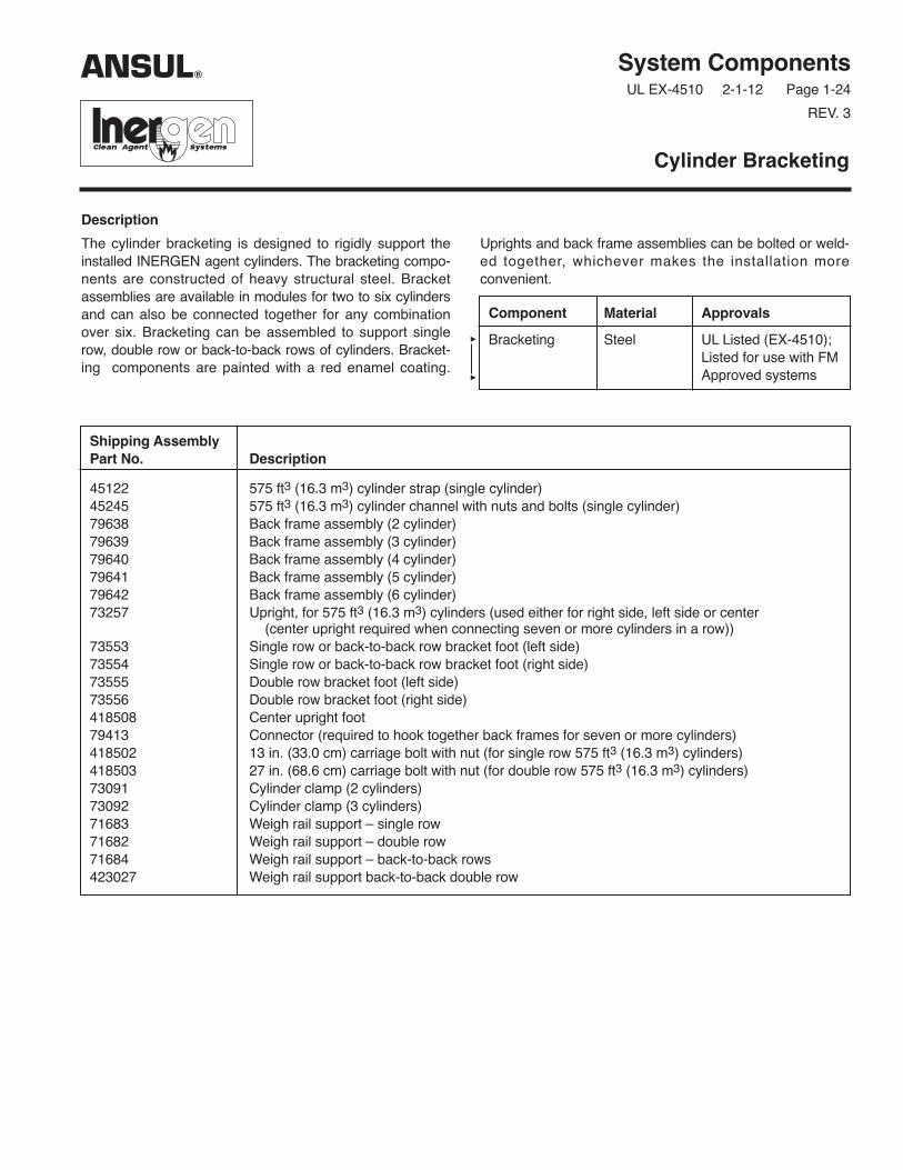
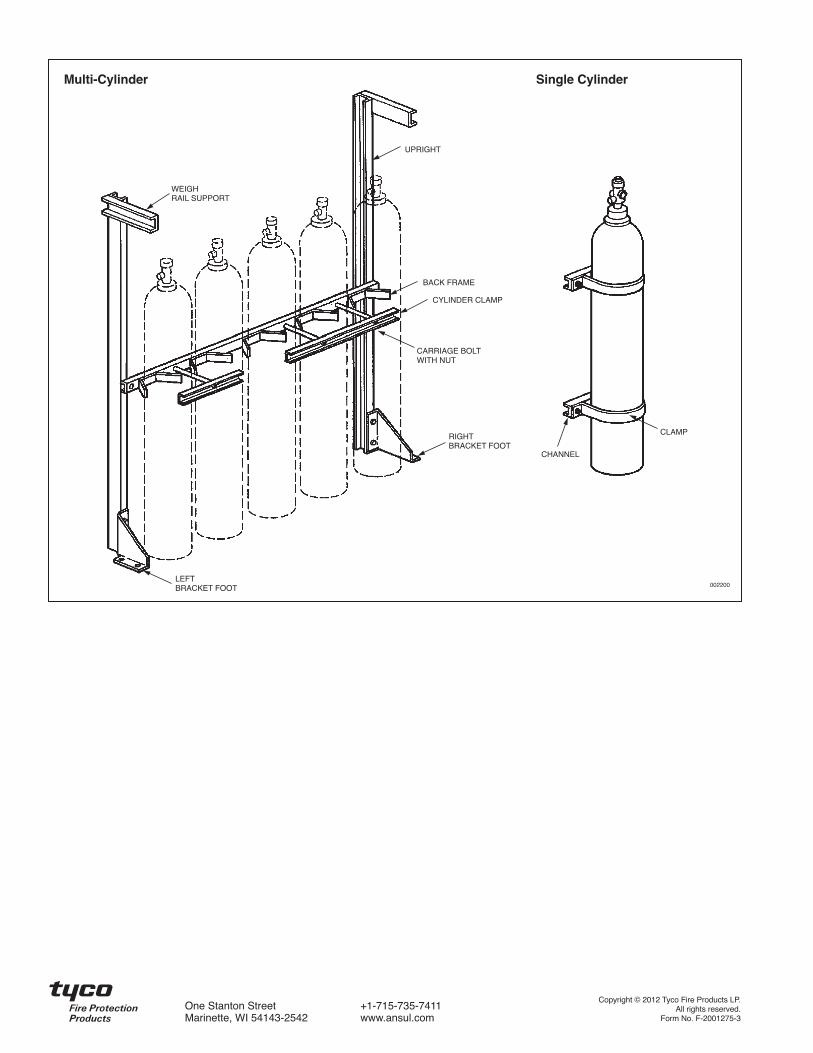
The cylinder bracketing is designed to rigidly support theinstalled INERGEN agent cylinders. The bracketing compo-nents are constructed of heavy structural steel. Bracketassemblies are available in modules for two to six cylindersand can also be connected together for any combinationover six. Bracketing can be assembled to support singlerow, double row or back-to-back rows of cylinders. Bracket -ing components are painted with a red enamel coating.
Uprights and back frame assemblies can be bolted or weld-ed together, whichever makes the installation more convenient.
Cylinder Bracketing
Component Material Approvals
Bracketing Steel UL Listed (EX-4510);Listed for use with FMApproved systems
Shipping AssemblyPart No. Description
45122 575 ft3 (16.3 m3) cylinder strap (single cylinder)45245 575 ft3 (16.3 m3) cylinder channel with nuts and bolts (single cylinder)79638 Back frame assembly (2 cylinder)79639 Back frame assembly (3 cylinder)79640 Back frame assembly (4 cylinder)79641 Back frame assembly (5 cylinder)79642 Back frame assembly (6 cylinder)73257 Upright, for 575 ft3 (16.3 m3) cylinders (used either for right side, left side or center
(center upright required when connecting seven or more cylinders in a row))73553 Single row or back-to-back row bracket foot (left side)73554 Single row or back-to-back row bracket foot (right side)73555 Double row bracket foot (left side)73556 Double row bracket foot (right side)418508 Center upright foot79413 Connector (required to hook together back frames for seven or more cylinders)418502 13 in. (33.0 cm) carriage bolt with nut (for single row 575 ft3 (16.3 m3) cylinders)418503 27 in. (68.6 cm) carriage bolt with nut (for double row 575 ft3 (16.3 m3) cylinders)73091 Cylinder clamp (2 cylinders)73092 Cylinder clamp (3 cylinders)71683 Weigh rail support – single row71682 Weigh rail support – double row71684 Weigh rail support – back-to-back rows423027 Weigh rail support back-to-back double row
ANSUL®
Multi-Cylinder Single Cylinder
UPRIGHT
BACK FRAME
CYLINDER CLAMP
CARRIAGE BOLTWITH NUT
RIGHTBRACKET FOOT
LEFTBRACKET FOOT
CHANNEL
002200
CLAMP
WEIGH RAIL SUPPORT
Copyright © 2012 Tyco Fire Products LP.All rights reserved.
Form No. F-2001275-3
One Stanton Street +1-715-735-7411Marinette, WI 54143-2542 www.ansul.com

System ComponentsUL EX-4510 2-1-12 Page 1-25
REV. 2
Description
The pressure switch is operated by the INERGEN agentpressure when the system is discharged. The pressureswitch can be used to open or close electrical circuits toeither shut down equipment or turn on lights or alarms. Thedouble pole, single throw (DPST) pressure switch is con-structed with a gasketed, water tight housing. The housingis constructed of malleable iron, painted red. A 1/4 in. NPTpressure inlet is used to connect the 1/4 in. pipe from theINERGEN system.
BAKELITE is a trademark of Union Carbide Corp.
The pressure switch can be installed either before or afterthe pressure reducer in the distribution piping.
Minimum operating pressure is 50 PSI (3.5 bar).
Pressure Switch – DPST
Shipping AssemblyPart No. Description
46250 Pressure switch – DPST
Component Material Thread Size/Type Electrical Rating Approvals
Pressure Switch Switch: Conduit Inlet: 3/4 in. NPT Female 2 HP – 240 VAC/ UL Listed (EX-4510);DPST BAKELITE Pressure Inlet: 1/4 in. NPT Female 480 VAC Listed for use with
Housing: 2 HP – 250 VDC, FM Approved
Malleable 30A – 250V AC/DC systems
Iron 5A – 480V AC/DC
Piston:Brass
Cover:Brass
MALLEABLE IRONFINISH – RED PAINT
BRASS RESETPLUNGER
MOISTURE-PROOFJOINT
GASKET NUT
“O” RING GASKET
NAMEPLATE
DOUBLE POLE –HEAVY DUTYTOGGLE SWITCHWITH FULLYENCLOSEDBAKELITE BASE
BRASS PISTON
PISTON “O” RINGGASKET
1/4 IN. UNION
3/4 IN.ELECTRICALCONDUITOUTLETS
TOPOWER
TO ELECTRICALEQUIPMENT TOBE CONTROLLED
1/4 IN. PIPEFROM CYLINDERS
000716
004593
3 5/8 IN.(9.2 cm)
2 7/8 IN.(7.3 cm)
4 9/16 IN.(11.5 cm)
19/64 IN. (7.5 mm)MOUNTING HOLE –TYP. 2 PLACES
ANSUL®
Copyright © 2012 Tyco Fire Products LP.All rights reserved.
Form No. F-2001276-2
One Stanton Street +1-715-735-7411Marinette, WI 54143-2542 www.ansul.com

Description
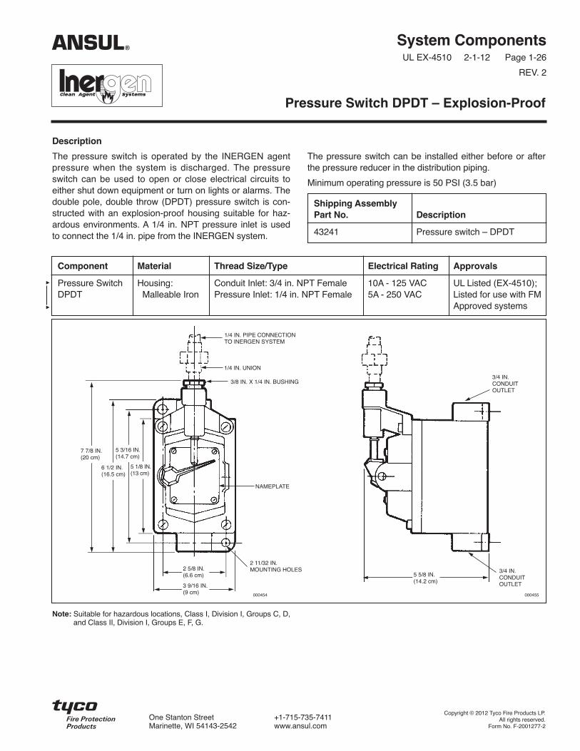
The pressure switch is operated by the INERGEN agentpressure when the system is discharged. The pressureswitch can be used to open or close electrical circuits toeither shut down equipment or turn on lights or alarms. Thedouble pole, double throw (DPDT) pressure switch is con-structed with an explosion-proof housing suitable for haz-ardous environments. A 1/4 in. NPT pressure inlet is usedto connect the 1/4 in. pipe from the INERGEN system.
Note: Suitable for hazardous locations, Class I, Division I, Groups C, D,and Class II, Division I, Groups E, F, G.
The pressure switch can be installed either before or afterthe pressure reducer in the distribution piping.
Minimum operating pressure is 50 PSI (3.5 bar)
System ComponentsUL EX-4510 2-1-12 Page 1-26
REV. 2
Pressure Switch DPDT – Explosion-Proof
Shipping AssemblyPart No. Description
43241 Pressure switch – DPDT
Component Material Thread Size/Type Electrical Rating Approvals
Pressure Switch Housing: Conduit Inlet: 3/4 in. NPT Female 10A - 125 VAC UL Listed (EX-4510);DPDT Malleable Iron Pressure Inlet: 1/4 in. NPT Female 5A - 250 VAC Listed for use with FM
Approved systems
1/4 IN. PIPE CONNECTIONTO INERGEN SYSTEM
1/4 IN. UNION
3/8 IN. X 1/4 IN. BUSHING
NAMEPLATE
2 11/32 IN.MOUNTING HOLES
7 7/8 IN.(20 cm)
6 1/2 IN.(16.5 cm)
5 3/16 IN.(14.7 cm)
5 1/8 IN.(13 cm)
3 9/16 IN.(9 cm)
5 5/8 IN.(14.2 cm)
2 5/8 IN.(6.6 cm)
3/4 IN.CONDUITOUTLET
000455000454
3/4 IN.CONDUITOUTLET
ANSUL®
Copyright © 2012 Tyco Fire Products LP.All rights reserved.
Form No. F-2001277-2
One Stanton Street +1-715-735-7411Marinette, WI 54143-2542 www.ansul.com


The pressure switch can be installed either before or afterthe pressure reducer in the distribution piping.
Minimum operating pressure is 50 PSI (3.5 bar)
Description
The pressure switch is operated by the INERGEN agentpressure when the system is discharged. The pressureswitch can be used to open or close electrical circuits toeither shut down equipment or turn on lights or alarms. Thethree pole, single throw (3PST) pressure switch is con-structed with a gasketed, water tight housing. The switchmay be used for 3 phase wiring requirements. The housingis constructed of malleable iron, painted red. A 1/4 in. NPTpressure inlet is used to connect the 1/4 in. pipe from theINERGEN system.
System ComponentsUL EX-4510 2-1-12 Page 1-27
REV. 2
Pressure Switch – 3PST
Shipping AssemblyPart No. Description
42344 Pressure switch – 3PST
Component Material Thread Size/Type Electrical Rating Approvals
Pressure Switch Switch: Conduit Inlet: 30A - 240 VAC UL Listed (EX-4510);3PST BAKELITE 3/4 in. NPT Female 20A - 600 VAC Listed for use with
Housing: Pressure Inlet: 3 HP - 120 VAC FM Approved systems
Malleable 1/4 in. NPT Female 7.5 HP - 240 VACIron 15 HP - 600 VAC
Piston: 3 PHASE ACBrass
RESET KNOB
SPRING
HALF ROUND ARM
SNAP LOCK-RING
“O” RING GASKET
PISTON ROD
UNION
SWIVEL NUT
NAMEPLATE
SPRING
HALF ROUND ARM
3/4 IN. NPT
3/4 IN. BRASSPLUG
HEX BUSHING3/8 IN. X 1/4 IN.
SECTION “A” – “A”
PISTON ROD
PISTON-SPOT NUT
PISTON
PISTON “O” RING GASKET
BRASSSWITCHHOUSING
TOGGLE SWITCH WITH FULLYENCLOSEDBAKELITE BASE
MOISTURE-PROOFGASKET
“A”000715
“A”
4 – 9/32 IN.MOUNTING HOLES
5 3/16 IN.(13.1 cm)
3 7/8 IN.(9.8 cm)
4 IN.(10.1 cm)
3 1/16 IN.(7.7 cm)
3 3/4 IN.(9.5 cm)
SPACER
ANSUL®
BAKELITE is a trademark of Union Carbide Corp
Copyright © 2012 Tyco Fire Products LP.All rights reserved.
Form No. F-2001278-2
One Stanton Street +1-715-735-7411Marinette, WI 54143-2542 www.ansul.com


System ComponentsUL EX-4510 2-1-12 Page 1-28
REV. 2
Description
The pressure trip is connected to the actuation or dischargeline of an INERGEN system. By either pneumatic or manu-al actuation, the pressure trip can release spring or weightpowered devices to close doors and windows, open fueldump valves, close fire dampers or close fuel supplyvalves. The pressure trip is constructed of brass with two1/4 in. NPT fittings for connection to discharge or actuationlines. The link on the pressure switch is released eitherpneumatically, by agent discharge pressure; or manually,
by use of the pull ring. The link then releases the devicewhich performs the auxiliary functions.
Note: Operating pressure must be a minimum of 75 psi(5.2 bar) with a maximum load of 70 lb (31.8 kg).
Pressure Trip
Shipping AssemblyPart No. Description
5156 Pressure trip
Component Material Thread Size/Type Approvals
Pressure Trip Brass 1/4 in. NPT Female UL Listed (EX-4510); Listed for usewith FM Approved systems
3 3/4 IN.(9.5 cm)
1/4 IN. NPT
000452
3 IN.(7.6 cm)
ANSUL®
Copyright © 2012 Tyco Fire Products LP.All rights reserved.
Form No. F-2001279-2
One Stanton Street +1-715-735-7411Marinette, WI 54143-2542 www.ansul.com


System ComponentsUL EX-4510 2-1-12 Page 1-29
REV. 2
Description
The Pressure Test Assembly, Part No. 427953, is requiredto properly perform the semi-annual pressure check perNFPA 2001. The pressure test assembly consists of a cali-brated gauge, adaptor, and handwheel. The assembly isattached to the fill port of the INERGEN valve. As the hand-wheel is turned in, the fill port is opened and the pressure isread on the gauge. After verifying the pressure in the cylin-der, the handwheel is turned out, closing the fill port, andthe assembly can be removed.
Pressure Test Assembly
ShippingAssemblyPart No. Description
427953 Pressure Test Assembly – CV-98
Component Material Approvals
Handwheel Cast Zinc Alloy UL Listed Body Brass (EX-4510);Adaptor Brass Listed for useGauge Stainless with FM
Steel Case ApprovedLaminated systemsSafetyGlass Lens
003686
ANSUL®
Copyright © 2012 Tyco Fire Products LP.All rights reserved.
Form No. F-2001280-2
One Stanton Street +1-715-735-7411Marinette, WI 54143-2542 www.ansul.com

System ComponentsUL EX-4510 2-1-12 Page 1-29.1
Description
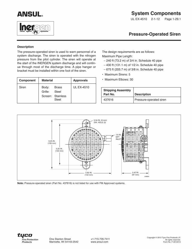
The pressure-operated siren is used to warn personnel of asystem discharge. The siren is operated with the nitrogenpressure from the pilot cylinder. The siren will operate atthe start of the INERGEN system discharge and will contin-ue through most of the discharge time. A pipe hanger orbracket must be installed within one foot of the siren.
The design requirements are as follows:
Maximum Pipe Length:
– 240 ft (73.2 m) of 3/4 in. Schedule 40 pipe
– 430 ft (131.1 m) of 1/2 in. Schedule 40 pipe
– 675 ft (205.7 m) of 3/8 in. Schedule 40 pipe
• Maximum Sirens: 5
• Maximum Elbows: 30
Pressure-Operated Siren
Component Material Approvals
Siren Body: Brass UL EX-4510
Grille: Steel
Screen: StainlessSteel
Shipping AssemblyPart No. Description
437616 Pressure-operated siren
ANSUL®
1/4 IN.NPTINLET
6.25 IN.(159 mm)
5.60 IN.(142 mm)
008806
0.34 IN. (9 mm)DIA. HOLE (2)
3.42 IN.(87 mm)
5.25 IN.(133 mm)
Copyright © 2012 Tyco Fire Products LP.All rights reserved.
Form No. F-2012013
One Stanton Street +1-715-735-7411Marinette, WI 54143-2542 www.ansul.com
Note: Pressure-operated siren (Part No. 437616) is not listed for use with FM Approved systems.

System ComponentsUL EX-4510 2-1-12 Page 1-30
REV. 2
Description
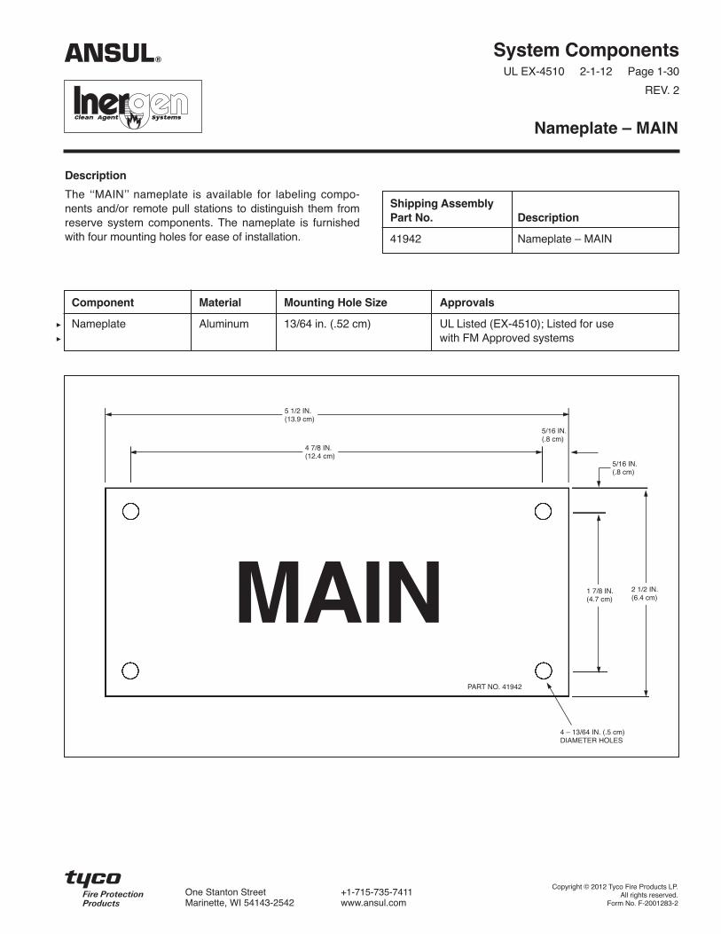
The ʻʻMAINʼʼ nameplate is available for labeling compo-nents and/or remote pull stations to distinguish them fromreserve system components. The nameplate is furnishedwith four mounting holes for ease of installation.
Nameplate – MAIN
Shipping AssemblyPart No. Description
41942 Nameplate – MAIN
Component Material Mounting Hole Size Approvals
Nameplate Aluminum 13/64 in. (.52 cm) UL Listed (EX-4510); Listed for usewith FM Approved systems
MAIN
5 1/2 IN.(13.9 cm)
4 7/8 IN.(12.4 cm)
1 7/8 IN.(4.7 cm)
2 1/2 IN.(6.4 cm)
5/16 IN.(.8 cm)
5/16 IN.(.8 cm)
PART NO. 41942
4 – 13/64 IN. (.5 cm)DIAMETER HOLES
ANSUL®
Copyright © 2012 Tyco Fire Products LP.All rights reserved.
Form No. F-2001283-2
One Stanton Street +1-715-735-7411Marinette, WI 54143-2542 www.ansul.com

System ComponentsUL EX-4510 2-1-12 Page 1-31
REV. 2
Description
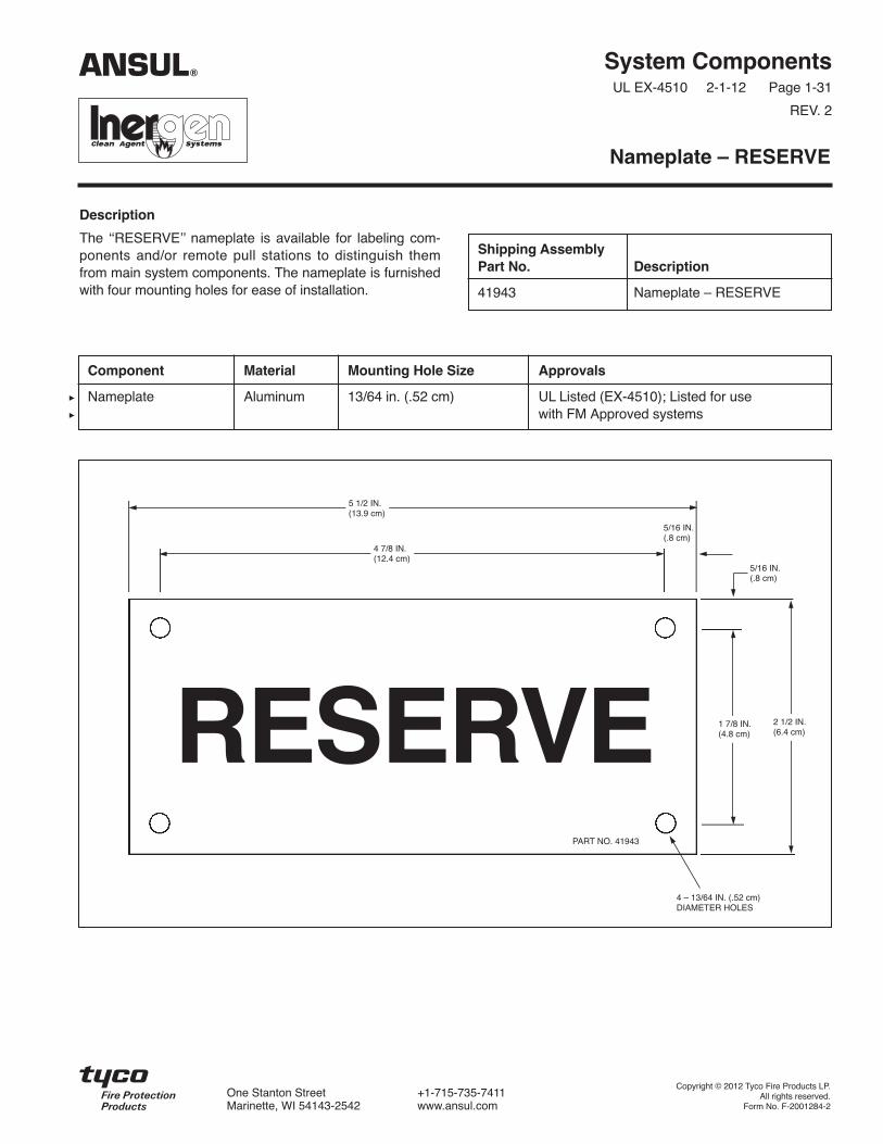
The ʻʻRESERVEʼ ̓ nameplate is available for labeling com-ponents and/or remote pull stations to distinguish themfrom main system components. The nameplate is furnishedwith four mounting holes for ease of installation.
Nameplate – RESERVE
Shipping AssemblyPart No. Description
41943 Nameplate – RESERVE
Component Material Mounting Hole Size Approvals
Nameplate Aluminum 13/64 in. (.52 cm) UL Listed (EX-4510) ; Listed for usewith FM Approved systems
RESERVE
5 1/2 IN.(13.9 cm)
4 7/8 IN.(12.4 cm)
1 7/8 IN.(4.8 cm)
2 1/2 IN.(6.4 cm)
5/16 IN.(.8 cm)
5/16 IN.(.8 cm)
PART NO. 41943
4 – 13/64 IN. (.52 cm)DIAMETER HOLES
ANSUL®
Copyright © 2012 Tyco Fire Products LP.All rights reserved.
Form No. F-2001284-2
One Stanton Street +1-715-735-7411Marinette, WI 54143-2542 www.ansul.com

System ComponentsUL EX-4510 2-1-12 Page 1-32
REV. 2
Description
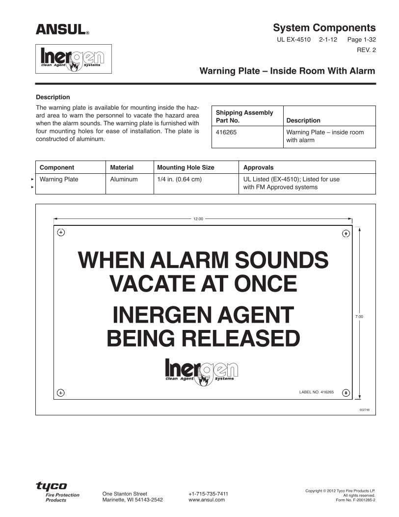
The warning plate is available for mounting inside the haz-ard area to warn the personnel to vacate the hazard areawhen the alarm sounds. The warning plate is furnished withfour mounting holes for ease of installation. The plate isconstructed of aluminum.
Warning Plate – Inside Room With Alarm
Shipping AssemblyPart No. Description
416265 Warning Plate – inside roomwith alarm
Component Material Mounting Hole Size Approvals
Warning Plate Aluminum 1/4 in. (0.64 cm) UL Listed (EX-4510); Listed for usewith FM Approved systems
WHEN ALARM SOUNDSVACATE AT ONCEINERGEN AGENT
BEING RELEASED
12.00
7.00
LABEL NO. 416265
002746
ANSUL®
Copyright © 2012 Tyco Fire Products LP.All rights reserved.
Form No. F-2001285-2
One Stanton Street +1-715-735-7411Marinette, WI 54143-2542 www.ansul.com


System ComponentsUL EX-4510 2-1-12 Page 1-33
REV. 2
Description
The warning plate is available for mounting outside thehazard area to warn the personnel that the space is pro-tected by an INERGEN system and no one should enterafter a discharge without being properly protected. Thewarning plate is furnished with four mounting holes for easeof installation.
Warning Plate – Outside Room Without Alarm
Shipping AssemblyPart No. Description
416266 Warning Plate – outsideroom
Component Material Mounting Hole Size Approvals
Warning Plate Aluminum 7/32 in. (0.56 cm) UL Listed (EX-4510); Listed for usewith FM Approved systems
WARNINGTHIS SPACE IS PROTECTED BY AN INERGENFIRE SUPPRESSION SYSTEM.
WHEN SYSTEM IS DISCHARGED AS A RESULTOF FIRE, CAUTION MUST BE TAKEN TO AVOIDEXPOSURE TO PRODUCTS OF COMBUSTION.
DO NOT ENTER WITHOUT APPROVED SELF-CONTAINED BREATHING APPARATUS ORUNTIL VENTILATION HAS BEEN OPERATEDFOR AT LEAST 15 MINUTES.
8.00
7.00
LABEL NO. 416266
002747
ANSUL®
Copyright © 2012 Tyco Fire Products LP.All rights reserved.
Form No. F-2001286-2
One Stanton Street +1-715-735-7411Marinette, WI 54143-2542 www.ansul.com


