
Stability of Structures.. Elastic, Inelastic, Fracture, And Damage Theories

Inelastic Behaviors 6 - 1Instructional Material Complementing FEMA 451, Design Examples
INELASTIC BEHAVIOR OF MATERIALS AND STRUCTURES
Inelastic Behaviors 6 - 2Instructional Material Complementing FEMA 451, Design Examples
• Illustrates inelastic behavior of materials and structures
• Explains why inelastic response may be necessary
• Explains the “equal displacement “ concept
• Introduces the concept of inelastic design response spectra
• Explains how inelastic behavior is built into the NEHRP Recommended Provisions and ASCE 7-05
Inelastic Behavior of Materials and Structures
Inelastic Behaviors 6 - 3Instructional Material Complementing FEMA 451, Design Examples
Importance in Relation to ASCE 7-05
• Derivation and explanation of the response reduction factor, R
• Derivation and explanation of the displacement amplification factor, Cd
• Derivation and explanation of the overstrength factor, Ωo
Inelastic Behaviors 6 - 4Instructional Material Complementing FEMA 451, Design Examples
Inelastic Behavior of Structures
From material
to cross section
to critical region
to structure
Inelastic Behaviors 6 - 5Instructional Material Complementing FEMA 451, Design Examples
Idealized Inelastic BehaviorFrom Material…..
Strain
Stress
σ y
ε y ε u
σ u
μ εεε = u
y
Inelastic Behaviors 6 - 6Instructional Material Complementing FEMA 451, Design Examples
Stress-Strain Relationships for Steel
20
Strain, in/in
Stress, ksi
40
60
80
00.0250.005 0.010 0.015 0.020

Inelastic Behaviors 6 - 7Instructional Material Complementing FEMA 451, Design Examples
Stress-Strain Relationships for Steel
Inelastic Behaviors 6 - 8Instructional Material Complementing FEMA 451, Design Examples
Stress-Strain Relationships for Concrete(Unconfined and Confined)
2
Strain, in/in
Stress, ksi
4
6
0Unconfined
Confined
0.0100.002 0.004 0.006 0.008
Inelastic Behaviors 6 - 9Instructional Material Complementing FEMA 451, Design Examples
Concrete Confinement
Inelastic Behaviors 6 - 10Instructional Material Complementing FEMA 451, Design Examples
Unconfined
Confined
Inelastic Behaviors 6 - 11Instructional Material Complementing FEMA 451, Design Examples
Benefits of Confinement
Spiral Confinement
Virtually NO Confinement
Olive View Hospital, 1971 San Fernando Valley earthquake
Inelastic Behaviors 6 - 12Instructional Material Complementing FEMA 451, Design Examples
Idealized Inelastic BehaviorTo Section…..
Strain Stress Moment
ε y σ y M y
φ y
Strain Stress Moment
ε u σ u Mu
φ u
ELASTIC
INELASTIC

Inelastic Behaviors 6 - 13Instructional Material Complementing FEMA 451, Design Examples
Curvature
Moment
M y
φ y φ u
Mu
μ φφφ = u
y
NOTE: μ μφ ε≤
Idealized Inelastic BehaviorTo Section…..
Inelastic Behaviors 6 - 14Instructional Material Complementing FEMA 451, Design Examples
Software for Moment - Curvature Analysis“XTRACT”
Inelastic Behaviors 6 - 15Instructional Material Complementing FEMA 451, Design Examples
LP
Moment
Curvature
M yMu
φ y
φ u
Area u≈ θ
Area y≈ θ
Idealized Inelastic BehaviorTo Critical Region and Member
θ y θ u
ELASTIC INELASTIC
Inelastic Behaviors 6 - 16Instructional Material Complementing FEMA 451, Design Examples
Rotation
Moment
M y
θ y θ u
Mu
μ θθθ = u
y
NOTE: μ μ μθ θ φ≤ ≤
Idealized Inelastic BehaviorTo Critical Region and Member
Inelastic Behaviors 6 - 17Instructional Material Complementing FEMA 451, Design Examples
Critical Region Behavior of a Steel Girder
Inelastic Behaviors 6 - 18Instructional Material Complementing FEMA 451, Design Examples
Idealized Inelastic BehaviorTo Structure…..
Force
Displacement
μΔΔΔ
= u
y
μ μθΔ ≤Note:

Inelastic Behaviors 6 - 19Instructional Material Complementing FEMA 451, Design Examples
Loss of Ductility Through Hierarchy
Strain με = 100
Curvature μφ = 12 to 20
Rotation μθ = 8 to 14
Displacement μΔ = 4 to 10
Inelastic Behaviors 6 - 20Instructional Material Complementing FEMA 451, Design Examples
• System ductility of 4 to 6 is required for acceptable seismic behavior.
• Good hysteretic behavior requires ductile materials. However, ductility in itself is insufficient to provide acceptable seismic behavior.
• Cyclic energy dissipation capacity is a better indicator of performance.
Ductility and Energy Dissipation Capacity
Inelastic Behaviors 6 - 21Instructional Material Complementing FEMA 451, Design Examples
Response Under ReversedCyclic “Loading”
+ Δ
Time
Earthquakes impose DEFORMATIONS. Internal forces developas a result of the deformations.
Δ(t)
Inelastic Behaviors 6 - 22Instructional Material Complementing FEMA 451, Design Examples
Load Cell
HydraulicRamRecords (F)
DisplacementTransducer(Controls Δ)
Laboratory Specimen under Cyclic Deformation Loading
+Δ
Time
1
8
7
6
5
4
3
2
Moment Arm L
Deformations are cyclic, inelastic, and “reversed”
Inelastic Behaviors 6 - 23Instructional Material Complementing FEMA 451, Design Examples
Laboratory Specimen Under Cyclic Deformation Loading
Measured HystereticBehavior
Force
Deformation
Load Cell
HydraulicRamRecords (F)
DisplacementTransducer(Controls Δ)
Moment Arm L
Inelastic Behaviors 6 - 24Instructional Material Complementing FEMA 451, Design Examples
Deformation Deformation
Force Force
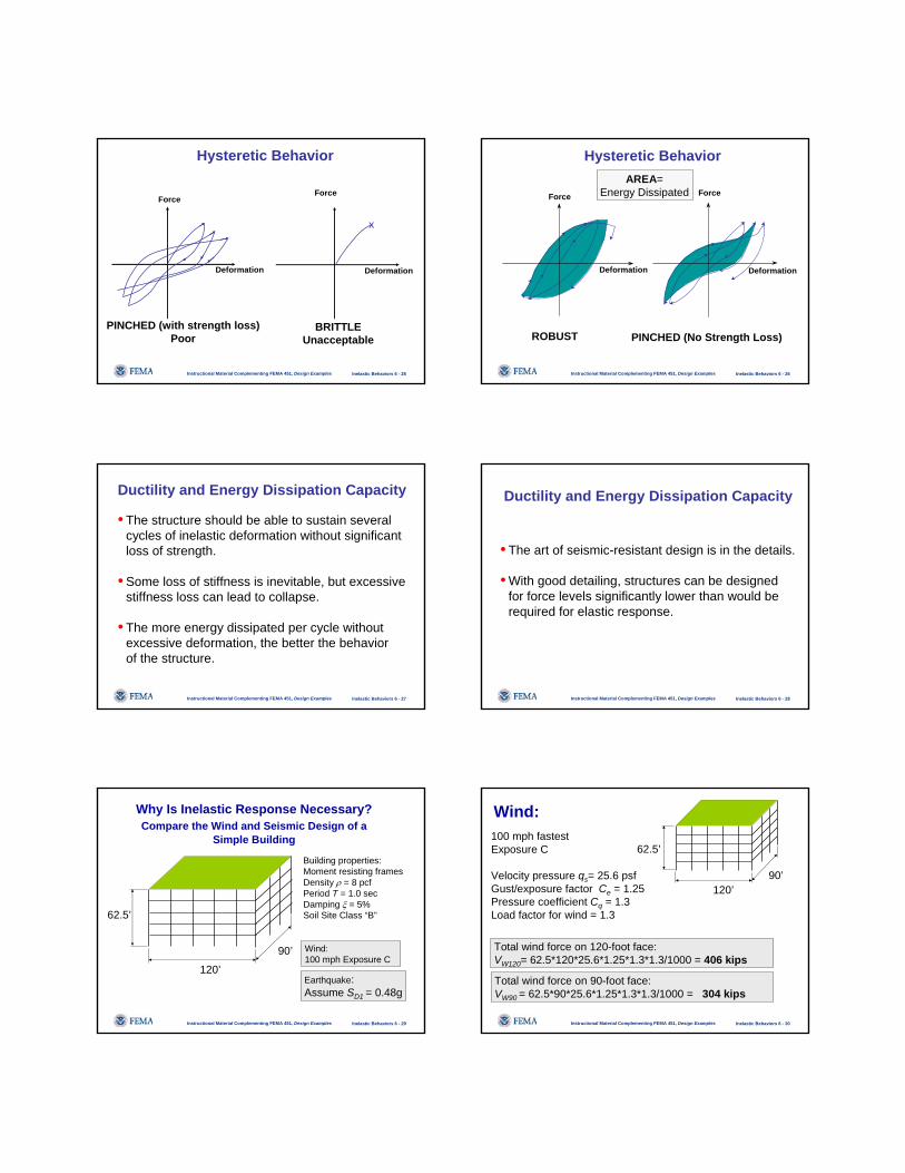
ROBUST(Excellent)
PINCHED(Good)
Hysteretic Behavior
Inelastic Behaviors 6 - 25Instructional Material Complementing FEMA 451, Design Examples
Deformation Deformation
ForceForce
Hysteretic Behavior
PINCHED (with strength loss)Poor
x
BRITTLEUnacceptable
Inelastic Behaviors 6 - 26Instructional Material Complementing FEMA 451, Design Examples
Deformation Deformation
Force Force
ROBUST
Hysteretic Behavior
PINCHED (No Strength Loss)
AREA=Energy Dissipated
Inelastic Behaviors 6 - 27Instructional Material Complementing FEMA 451, Design Examples
• The structure should be able to sustain several cycles of inelastic deformation without significantloss of strength.
• Some loss of stiffness is inevitable, but excessivestiffness loss can lead to collapse.
• The more energy dissipated per cycle withoutexcessive deformation, the better the behaviorof the structure.
Ductility and Energy Dissipation Capacity
Inelastic Behaviors 6 - 28Instructional Material Complementing FEMA 451, Design Examples
• The art of seismic-resistant design is in the details.
• With good detailing, structures can be designedfor force levels significantly lower than would berequired for elastic response.
Ductility and Energy Dissipation Capacity
Inelastic Behaviors 6 - 29Instructional Material Complementing FEMA 451, Design Examples
Why Is Inelastic Response Necessary?Compare the Wind and Seismic Design of a
Simple Building
120’
90’
62.5’
Earthquake:Assume SD1 = 0.48g
Wind:100 mph Exposure C
Building properties:Moment resisting framesDensity ρ = 8 pcfPeriod T = 1.0 secDamping ξ = 5%Soil Site Class “B”
Inelastic Behaviors 6 - 30Instructional Material Complementing FEMA 451, Design Examples
Wind:
120’90’
62.5’100 mph fastest Exposure C
Velocity pressure qs= 25.6 psfGust/exposure factor Ce = 1.25Pressure coefficient Cq = 1.3Load factor for wind = 1.3
Total wind force on 120-foot face:VW120= 62.5*120*25.6*1.25*1.3*1.3/1000 = 406 kips
Total wind force on 90-foot face:VW90 = 62.5*90*25.6*1.25*1.3*1.3/1000 = 304 kips

Inelastic Behaviors 6 - 31Instructional Material Complementing FEMA 451, Design Examples
Earthquake:
120’90’
62.5’Building weight, W =120*90*62.5*8/1000 = 5400 kips
Total ELASTIC earthquake force (in each direction):VEQ = 0.480*5400 = 2592 kips
C ST R IS
D= = =1 0 4810 10 10
0 480( / )
.. ( . / . )
.
WCV SEQ =
Inelastic Behaviors 6 - 32Instructional Material Complementing FEMA 451, Design Examples
Comparison: Earthquake vs. Wind
120
2592 6.4406
EQ
W
VV
= =90
2592 8.5304
EQ
W
VV
= =
• ELASTIC earthquake forces 6 to 9 times wind!
• Virtually impossible to obtain economical design
Inelastic Behaviors 6 - 33Instructional Material Complementing FEMA 451, Design Examples
How to Deal with Huge Earthquake Force?
• Isolate structure from ground (base isolation)
• Increase damping (passive energy dissipation)
• Allow controlled inelastic response
Historically, building codes use inelastic response procedure.Inelastic response occurs through structural damage (yielding).We must control the damage for the method to be successful.
Inelastic Behaviors 6 - 34Instructional Material Complementing FEMA 451, Design Examples
Force, kips
Displacement, inches4.0
400
200
1.0 2.0 3.0
600
5.0
Actual
Idealized
Assume Frame Is Designed for Wind“Pushover” Analysis Predicts Strength = 500 k
Inelastic Behaviors 6 - 35Instructional Material Complementing FEMA 451, Design Examples
Force, kips
4.0
400
200
1.0 2.0 3.0
600
5.0
Fy=500 k
K1=550 k/in
K2=11 k/in
How Will Frame Respond During 0.4g El Centro Earthquake?
Idealized SDOF Model
-0.6
-0.4
-0.2
0
0.2
0.4
0.6
0 2 4 6 8 10 12 14 16 18 20
T ime, S econd s
Acc
eler
atio
n, g
Displacement, in.El Centro Ground Motion
Inelastic Behaviors 6 - 36Instructional Material Complementing FEMA 451, Design Examples
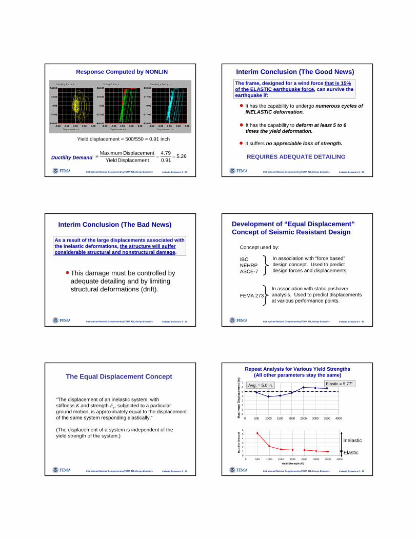
Response Computed by NONLIN
Maximumdisplacement:
Number ofyield events:
Maximumshear force:
4.79”
542 k
15
Inelastic Behaviors 6 - 37Instructional Material Complementing FEMA 451, Design Examples
Response Computed by NONLIN
Yield displacement = 500/550 = 0.91 inch
Maximum Displacement 4.79 5.26Yield Displacement 0.91
≡ = =Ductility Demand
Inelastic Behaviors 6 - 38Instructional Material Complementing FEMA 451, Design Examples
Interim Conclusion (The Good News)The frame, designed for a wind force that is 15% of the ELASTIC earthquake force, can survive theearthquake if:
It has the capability to undergo numerous cycles ofINELASTIC deformation.
It suffers no appreciable loss of strength.
It has the capability to deform at least 5 to 6 times the yield deformation.
REQUIRES ADEQUATE DETAILING
Inelastic Behaviors 6 - 39Instructional Material Complementing FEMA 451, Design Examples
Interim Conclusion (The Bad News)
As a result of the large displacements associated withthe inelastic deformations, the structure will sufferconsiderable structural and nonstructural damage.
This damage must be controlled byadequate detailing and by limiting structural deformations (drift).
Inelastic Behaviors 6 - 40Instructional Material Complementing FEMA 451, Design Examples
Development of “Equal Displacement”Concept of Seismic Resistant Design
Concept used by:
IBCNEHRPASCE-7
FEMA 273
In association with “force based”design concept. Used to predictdesign forces and displacements
In association with static pushoveranalysis. Used to predict displacementsat various performance points.
Inelastic Behaviors 6 - 41Instructional Material Complementing FEMA 451, Design Examples
The Equal Displacement Concept
“The displacement of an inelastic system, withstiffness K and strength Fy, subjected to a particularground motion, is approximately equal to the displacementof the same system responding elastically.”
(The displacement of a system is independent of theyield strength of the system.)
Inelastic Behaviors 6 - 42Instructional Material Complementing FEMA 451, Design Examples
01
2345
67
0 500 1000 1500 2000 2500 3000 3500 4000
Yield Strength (K)
Max
imum
Dis
plac
emen
t (in
)
Repeat Analysis for Various Yield Strengths(All other parameters stay the same)
0
1
2
3
4
5
6
0 500 1000 1500 2000 2500 3000 3500 4000
Yield Strength (K)
Duc
tility
Dem
and
Avg. = 5.0 in.
Inelastic
Elastic
Elastic = 5.77”

Inelastic Behaviors 6 - 43Instructional Material Complementing FEMA 451, Design Examples
Constant Displacement Idealizationof Inelastic Response
0
500
1000
1500
2000
2500
3000
3500
0 2 4 6 8
Displacement, Inches
Forc
e, K
ips
ACTUAL BEHAVIOR
0
500
1000
1500
2000
2500
3000
3500
0 2 4 6 8
Displacement, inches
Forc
e, K
ips
IDEALIZED BEHAVIOR
Inelastic Behaviors 6 - 44Instructional Material Complementing FEMA 451, Design Examples
Equal Displacement Idealizationof Inelastic Response
• For design purposes, it may be assumed thatinelastic displacements are equal to thedisplacements that would occur during anelastic response.
• The required force levels under inelastic responseare much less than the force levels required forelastic response.
Inelastic Behaviors 6 - 45Instructional Material Complementing FEMA 451, Design Examples
0
500
1000
1500
2000
2500
3000
3500
0 2 4 6 8
Displacement, inches
Forc
e, K
ips
Elastic
Inelastic
Design for this force Design for this displacement
Equal Displacement Conceptof Inelastic Design
5.77
Inelastic Behaviors 6 - 46Instructional Material Complementing FEMA 451, Design Examples
0
500
1000
1500
2000
2500
3000
3500
0 2 4 6 8
Displacement, inches
Forc
e, K
ips
Elastic
Inelastic
du=5.77”dy=0.91”
Ductility supply MUST BE > ductility demand = 34.691.077.5
=
Equal Displacement Conceptof Inelastic Design
Inelastic Behaviors 6 - 47Instructional Material Complementing FEMA 451, Design Examples
0
500
1000
1500
2000
2500
3000
3500
0 2 4 6 8
Displacement, inches
Forc
e, K
ips
Using response spectra, estimate elastic force demand FE
Estimate ductility supply, μ, and determine inelastic force demand FI= FE /μ.. Design structure for FI.
Compute reduced displacement. dR, and multiply by μ to obtain true inelastic eisplacement, dI. Check drift using di.
FE
FI
dR dI
Inelastic Behaviors 6 - 48Instructional Material Complementing FEMA 451, Design Examples
ASCE 7 Approach
Use basic elastic spectrum but, for strength,divide all pseudoacceleration values by R,a response modification factor that accounts for:
• Anticipated ductility supply• Overstrength• Damping (if different than 5% critical)• Past performance of similar systems• Redundancy

Inelastic Behaviors 6 - 49Instructional Material Complementing FEMA 451, Design Examples
Ductility/Overstrength
Force
Displacement
DesignStrength
FIRST SIGNIFICANT YIELD
FirstSignificantYield
Inelastic Behaviors 6 - 50Instructional Material Complementing FEMA 451, Design Examples
First Significant Yield is the level of force that causes complete plastification of at least the most critical region of the structure (e.g., formation of the first plastic hinge).
The design strength of a structure is equal to the resistance at first significant yield.
Inelastic Behaviors 6 - 51Instructional Material Complementing FEMA 451, Design Examples
Force
Displacement
DesignStrength
Overstrength (1)
Inelastic Behaviors 6 - 52Instructional Material Complementing FEMA 451, Design Examples
Force
Displacement
DesignStrength
Overstrength (2)
Inelastic Behaviors 6 - 53Instructional Material Complementing FEMA 451, Design Examples
Force
Displacement
DesignStrength
Overstrength
Overstrength (3)
ApparentStrength
Inelastic Behaviors 6 - 54Instructional Material Complementing FEMA 451, Design Examples
Sources of Overstrength
• Sequential yielding of critical regions• Material overstrength (actual vs specified yield)• Strain hardening• Capacity reduction (φ ) factors• Member selection

Inelastic Behaviors 6 - 55Instructional Material Complementing FEMA 451, Design Examples
Design StrengthOverstrength
Apparent Strength
Force
Displacement
Overstrength Factor Ω = Apparent Strength Design Strength
Definition of Overstrength Factor Ω
Inelastic Behaviors 6 - 56Instructional Material Complementing FEMA 451, Design Examples
Design Strength
Apparent Strength
Force
Displacement
Definition of Ductility Reduction Factor Rd
Elastic StrengthDemand
Elastic Displacement Demand
StrengthDemandReduction dueTo Ductility
Overstrength
Inelastic Behaviors 6 - 57Instructional Material Complementing FEMA 451, Design Examples
Definition of Ductility Reduction Factor
Design Strength
Apparent Strength
Force
Displacement
Elastic StrengthDemand
Elastic Displacement Demand
StrengthDemandReduction dueTo Ductility
Overstrength
Ductility Reduction Rd = Elastic Strength Demand
Apparent Strength
Inelastic Behaviors 6 - 58Instructional Material Complementing FEMA 451, Design Examples
Ductility Reduction Rd = Elastic Strength Demand
Apparent Strength
Overstrength Factor Ω = Apparent Strength Design Strength
Elastic Strength Demand Design Strength
R =
Definition of Response ModificationCoefficient R
= Rd Ω
Inelastic Behaviors 6 - 59Instructional Material Complementing FEMA 451, Design Examples
Reduced (Design) Strength
Force
Displacement
R x Design Strength
Elastic Displacement Demand
Ω x Design Strength
Definition of Response ModificationCoefficient R
ANALYSIS DOMAIN
Inelastic Behaviors 6 - 60Instructional Material Complementing FEMA 451, Design Examples
Design Strength
Apparent Strength
Elastic StrengthDemand
Elastic Displacement Demand Δ E
Computed Design DisplacementDemand Δ D
Actual Inelastic DisplacementDemand Δ I
Definition of Deflection Amplification Factor Coefficient Cd

Inelastic Behaviors 6 - 61Instructional Material Complementing FEMA 451, Design Examples
ASCE 7 Approach for Displacements
Determine design forces: V = CsW, where Csincludes ductility/overstrength reduction factor R.
Distribute forces vertically and horizontally and compute displacements using linear elastic analysis.
Multiply computed displacements by Cd to obtainestimate of true inelastic response.
Inelastic Behaviors 6 - 62Instructional Material Complementing FEMA 451, Design Examples
Examples of Design Factors for Steel StructuresASCE 7-05
R Ωo Rd Cd
Special Moment Frame 8 3 2.67 5.5Intermediate Moment Frame 4.5 3 1.50 4.0Ordinary Moment Frame 3.5 3 1.17 3.0
Eccentric Braced Frame 8 2 4.00 4.0Eccentric Braced Frame (Pinned) 7 2 3.50 4.0
Special Concentric Braced Frame 6 2 3.00 5.0Ordinary Concentric Braced Frame 3.25 2 1.25 3.25
Not Detailed 3 3 1.00 3.0Note: Rd is ductility demand ONLY IF Ωo is achieved.
Inelastic Behaviors 6 - 63Instructional Material Complementing FEMA 451, Design Examples
Examples of Design Factorsfor Reinforced Concrete Structures
ASCE 7-05
R Ωo Rd Cd
Special Moment Frame 8 3 2.67 5.5Intermediate Moment Frame 5 3 1.67 4.5Ordinary Moment Frame 3 3 1.00 2.5
Special Reinforced Shear Wall 5 2.5 2.00 5.0Ordinary Reinforced Shear Wall 4 2.5 1.60 4.0Detailed Plain Concrete Wall 2 2.5 0.80 2.0Ordinary Plain Concrete Wall 1.5 2.5 0.60 1.5
Note: Rd is Ductility Demand ONLY IF Ωo is Achieved.
Inelastic Behaviors 6 - 64Instructional Material Complementing FEMA 451, Design Examples
C SR IS
DS=/
C ST R IS
D= 1
( / )
ASCE 7 Elastic Spectra asAdjusted for Ductility and Overstrength
0.0
0.2
0.4
0.6
0.8
1.0
1.2
0 1 2 3 4
Period, Seconds
Acc
eler
atio
n, g R=1
R=2R=3R=4R=6R=8
SDS=1.0g SD1=0.48g
Inelastic Behaviors 6 - 65Instructional Material Complementing FEMA 451, Design Examples
0.0
0.2
0.4
0.6
0.8
1.0
1.2
0.0 1.0 2.0 3.0 4.0 5.0
Period, Seconds
Pseu
doac
cele
ratio
n, g
R=1
R=4
0.15V=0.15W
Using Modified ASCE 7 Spectrumto Determine Force Demand
Inelastic Behaviors 6 - 66Instructional Material Complementing FEMA 451, Design Examples
Using Modified ASCE-7 Spectrumto Determine Displacement Demand
0
5
10
15
20
25
0 1 2 3 4 5
Period, Seconds
Dis
plac
emen
t,inc
hes.
R=1R=4(R=4)*Cd
Cd=3.5

Inelastic Behaviors 6 - 67Instructional Material Complementing FEMA 451, Design Examples
Displacements must be multiplied by factor Cd because displacements based on reduced force would be too low
ELASTICREDUCEDdINELASTIC C Δ×=Δ
0
5
10
15
20
25
0 1 2 3 4 5
Period, Seconds
Dis
plac
emen
t,inc
hes.
R=1R=4(R=4)*Cd
Cd = 3.5
3.65 .INELASTIC inΔ =
Inelastic Behaviors 6 - 68Instructional Material Complementing FEMA 451, Design Examples
“Equal displacement” approach may not beapplicable at very low period values.
Inelastic Behaviors 6 - 69Instructional Material Complementing FEMA 451, Design Examples
FE
I
Eyy
I
EEE F
FFFFE
2
5.05.0 δδ ==
yI
E
FF δ
EE
Equal Energy Concept(Applicable at Low Periods)
ELASTIC ENERGY
FI
Inelastic Behaviors 6 - 70Instructional Material Complementing FEMA 451, Design Examples
FI
δy δu
EI
( )0.5 0.5I I u I y I yE F F Fδ δ δ μ= − = −
Equal Energy Concept(Applicable at Low Periods)
INELASTIC ENERGY
Inelastic Behaviors 6 - 71Instructional Material Complementing FEMA 451, Design Examples
12 −= μI
E
FF
Assuming EE = EI :
FE
FI
Equal Energy Concept(Applicable at Low Periods)
Inelastic Behaviors 6 - 72Instructional Material Complementing FEMA 451, Design Examples
0.1
1
10
100
0.01 0.1 1 10Period, Seconds
Pseu
do V
eloc
ity, I
n/Se
c
Equal Energy
Elastic:
Inelastic:EqualDisp.
Transition
μE
IFF =
12 −=
μE
IFF
Newmark Inelastic Spectrum (for Psuedoacceleration)

Inelastic Behaviors 6 - 73Instructional Material Complementing FEMA 451, Design Examples
Newmark’sInelastic Design Response Spectrum
To obtain inelastic displacement spectrum, multiply the spectrum shown in previous slide by μ (for all periods).
Inelastic Behaviors 6 - 74Instructional Material Complementing FEMA 451, Design Examples
0.1
1
10
100
0.01 0.1 1 10Period, Seconds
Pseu
do V
eloc
ity, I
n/Se
c
Disp.
Accel.
Inelastic Design Response Spectrum for Acceleration & Displacement
Inelastic Behaviors 6 - 75Instructional Material Complementing FEMA 451, Design Examples
At very low periods, the ASCE 7 spectrum does not reduce toground acceleration so this partially compensates for“error” in equal displacement assumption at low periodvalues.
Note: FEMA 273 has explicit modifications for computing “target at low periods.”
Period, T
Cs


