Industrial Fiber Optic Networking - ultra-nspi.com, Schneider Electric ... Phoenix Contact, 5...
36
Weed Instrument Fiber Optics Industrial Fiber Optic Networking For Factory Automation and Process Control • PLC Modems • Ethernet Connectivity • Multiplexers • Analog/Digital Links • Training/Service EOTec Industrial Fiber Optic Networking For Factory Automation and Process Control Use Fiber Optic Networking to protect your critical systems. Fiber Optic Products
Transcript of Industrial Fiber Optic Networking - ultra-nspi.com, Schneider Electric ... Phoenix Contact, 5...

Weed Instrument Fiber Optics
Industrial Fiber Optic NetworkingFor Factory Automation and Process Control
•PLCModems•EthernetConnectivity•Multiplexers•Analog/DigitalLinks•Training/Service
EOTec
Industrial Fiber Optic NetworkingFor Factory Automation and Process Control
Use Fiber Optic Networking to protect your critical systems.
Fiber Optic Products

Commercialvs.IndustrialFiberOpticProductsMost process plants and factories have unique requirements for communications networks that differ from those of a commercial network. Industrial network components must withstand harsher environmental conditions such as extreme temperature ranges, lightning strikes, electromagnetic interference, and hazardous locations just to name a few. Mounting and space requirements are also an issue since industrial networking components must be mounted in the same control panel with other control equipment. At Weed Instrument, our goal is to meet the demanding requirements of industrial communication networks. The modular EOTec brand of industrially hardened fiber optic communication products addresses these issues and provides optimal solutions for factory automation and process control.
WhyFiberOptics?Fiber optics can be found in many applications, from network backbones that power the Internet to manufacturing facilities, to subsea communication networks on drilling rigs. The information carrying capacity of an optical fiber is far greater than it is for copper wire, coaxial cables, and microwave links. Optical fibers are very small, lightweight, resist corrosion, and are immune to electrical noise from lightning storms and electromagnetic interference (EMI/RFI). In addition, fiber optic cables do not carry electrical energy and are approved for hazardous locations. The cost of fiber optic cable and its associated connectors and hardware has decreased steadily over the years. Today, the benefits of fiber optics can far outweigh the costs making fiber optic communications the preferred choice for industrial factory automation and process control networks.
EthernetI/P
NetworkProtocols
FiberOpticModems
Overview of Networking SystemOverview of Networking System
NetworkProtocolSelf-HealingRing

NetworkProtocolsThe PLC has been on the forefront of factory automation for several decades and there are many different network protocols in use today. Network protocols are either open or proprietary. Some prominent proprietary protocols supported by Weed Instrument are Rockwell Automation’s DH+, Schneider Electric’s Modbus Plus™ and GE Fanuc’s Genius® Bus. Open protocols include Ethernet TCP/IP, Profibus, ControlNet™ and DeviceNet™. Weed Instrument supports the most common protocols in use today for industrial PLC networks and Ethernet Connectivity.
EthernetConnectivityEthernet is swiftly being adopted by the industrial automation and control industry. Ethernet addresses many of the requirements of proprietary PLC buses, with the added advantages of widespread usage and lower costs due to high volumes. Weed Instrument is continually developing new fiber optic products to support Ethernet and other emerging industrial network
protocols.
IndustrialEthernetSwitches
EthernetMedia
Converters
"EOTec" is a registered trademark of Weed Instrument Co. The EOTec product line is manufactured and distributed by Weed Instrument Co. "Genius" is a registered trademark of GE-FANUC. "ControlNet" is a trademark of ControlNet International Ltd. "Modbus Plus" is a trademark of Modicon. "DeviceNet" is a trademark of O.D.V.A.
-- Indicates fiber optic cable
-- Indicates copper cable
Key
FastEthernetSelf-Healing
Ring

System diagnostic indicators for continuous monitoring
during operation
5mm DIN-Rail mounting for compact efficient design with
smaller space and less power
Lightweight interchangeable modules facilitate custom configurations, easy expansion and reconfiguration
EOTec 2000 Modular SystemEOTec 2000 Modular System
Hot-Swappable, bus compatible Redundant Power Supplies with
diagnostic outputs to eliminate single point of failure, reducing the risk of significant costly system down-time
Pluggable Screw Terminals or indus-try standard connectors for all copper
cable connections
ElectricalInterfaceModules
Electrical Interface modules compatible with all major communications standards
Modular expandable fiber optic system for industrial networks
Power supplies for AC or DC power sources.
PowerSupplies

5
Network Topology capabilities beyond the limitations of wire-cable including Point-to-Point, Daisy Chain, Star
and Self-Healing Ring
Status indicators for functional optic/wire links and link activity indication
Optical and Electrical compatibility with EOTec 6000 modems
Cascade up to five optical engines on one power supply to achieve
the popular STAR topology
OpticalInterfaceModules
Extended temperature range (-40 to 85°C) for harsh industrial applications
Class I, Division 2, CE MarkedUL recognized power supplies
Continuous -0mA optical diagnostic outputInter-module communications
achieved via an integrated BUS-System, no external wiring
SMA or ST Connectors Multi and Single Mode
SC or ST Connectors
Remote Alarming
Patented Self-Healing Ring modules provide a "NO DATA LOSS" media
redundancy solution for highly reliable communications
Self-HealingRingModules
EthernetConnectivity
Ethernet to Fiber Media Converters, Switches

6
EOTec 2000 Fiber Optic ModemsEOTec 2000 Fiber Optic Modems
The Electrical Interface Module connects the EOTec 000 system to factory networking communication devices. It provides electrical interface conditioning for data transmission over the fiber optic network.
The basic modem configuration consists of a Power Supply, an Electrical Interface, and an Optical Interface Module. However, additional modules may be added to configure Daisy Chain, Star and Self-Healing Ring topologies and provide redundancy.
ElectricalInterfaceModules-CommonFeaturesAmbientConditions: -0 to 85°C Operational, 0 to 95% Rel. Humidity Non-CondensingPowerRequirement(Bus): 9VDC @ 00mA Max per modulePowerIndicator:Green LEDCommunicationsActivityIndicator:Amber LEDCertifications: FM Approved Class I, Division , Groups A, B, C & D (selected models only)
ElectricalInterfaceModules
Note: Weed Instrument is constantly developing new EOTec modules for different protocols. Please visit our website at www.weedinstrument.com for an updated list of the most current modules.
RS-232RS-485
ModelNumber 2C02 2C072C10 Protocol GE Genius/Remote I/O Reliance R-Net/ RS- or andextrafeatures Remote I/O RS-85 Multi-drop RS-: 9.6K-5K Baud CommunicationsDataRate 5.6K Baud Extended 800K Baud RS-85: 9.6K-0K Baud Half Duplex Pluggable ScrewTerminal Pluggable Screw Terminal CopperCableConnector to AWG BNC to AWG (0.5-.mm) (0.5-.mm) Cage-Clamp Cage-Clamp CopperCableEndTermination None Internal - 75 ohms RS-: N/A RS-85:None
MaximumDevicesandCopperCable RS-: Unit, 50ft (5m) LengthSupportedperModule Units, 500ft (km) Unit, 00ft (50m) RS-85: 0 Units, 000ft (.km)

7
EOTec 2000 Fiber Optic ModemsEOTec 2000 Fiber Optic Modems
Mechanical Specifications: Single-width EOTec 000 Modules (Includes most Electrical and Optical Modules). See Power Supply section for double-width dimensions.Mounting: 5mm DIN RailWeight: <9oz (50g)
9.6K, 9.K, 5.5K, 9.75K, 87.5K, 500K, .5M,
.0M, 6.0M and .0M
DB-9 Pin
.0M Baud
Profibus - DPC - Self-Healing Ringand External VDC pwr.
None
Per ProfibusSpecifications
2C22/2C23
SeenextpageformoreElectrical
InterfaceModules
F-Type
2C14
Modicon Remote I/O
.5M Baud
Internal, 75 Ohms
0 dB of cable and tap loss
DB-9 Pin
Modicon Modbus Plus
Per Modbus PlusSpecifications
2C29
None
2C21
DeviceNet
5kbps
Pluggable, Phoenix Contact, 5 Position in Line, Screw Terminal
Block, Dual Wire Entries, Accepts to AWG
Dip Switch (Selectable)
Per DeviceNetSpecifications
ModelNumber 2C02 2C072C10 Protocol GE Genius/Remote I/O Reliance R-Net/ RS- or andextrafeatures Remote I/O RS-85 Multi-drop RS-: 9.6K-5K Baud CommunicationsDataRate 5.6K Baud Extended 800K Baud RS-85: 9.6K-0K Baud Half Duplex Pluggable ScrewTerminal Pluggable Screw Terminal CopperCableConnector to AWG BNC to AWG (0.5-.mm) (0.5-.mm) Cage-Clamp Cage-Clamp CopperCableEndTermination None Internal - 75 ohms RS-: N/A RS-85:None
MaximumDevicesandCopperCable RS-: Unit, 50ft (5m) LengthSupportedperModule Units, 500ft (km) Unit, 00ft (50m) RS-85: 0 Units, 000ft (.km)
8
EOTec 2000 Fiber Optic ModemsEOTec 2000 Fiber Optic Modems
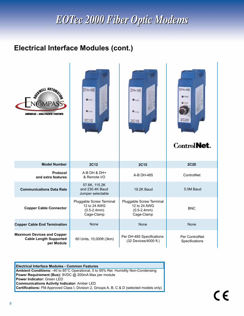
ElectricalInterfaceModules(cont.)
Protocolandextrafeatures
9.K Baud
CopperCableEndTermination
ModelNumber
CommunicationsDataRate
MaximumDevicesandCopper CableLengthSupported
perModule
BNCCopperCableConnector
5.0M Baud
A-B DH-85 ControlNet
None
Per DH-485 Specifications ( Devices/000 ft.)
Per ControlNetSpecifications
2C202C15
None
Pluggable Screw Terminal to AWG(0.5-.mm)Cage-Clamp
2C12
Pluggable Screw Terminal to AWG(0.5-.mm)Cage-Clamp
57.6K, 5.K and 0.K Baud Jumper selectable
A-B DH & DH+& Remote I/O
60 Units, 0,000ft (km)
None
ElectricalInterfaceModules-CommonFeaturesAmbientConditions: -0 to 85°C Operational, 0 to 95% Rel. Humidity Non-CondensingPowerRequirement(Bus): 9VDC @ 00mA Max per modulePowerIndicator:Green LEDCommunicationsActivityIndicator:Amber LEDCertifications: FM Approved Class I, Division , Groups A, B, C & D (selected models only)
9
ControlNet PLC
A B
ControlNet PLC
A B
ControlNet PLC
A B
ControlNet PLC
A B
ControlNet PLC
A B
ControlNet PLC
A B
ControlNet PLC
A B
ControlNet PLC
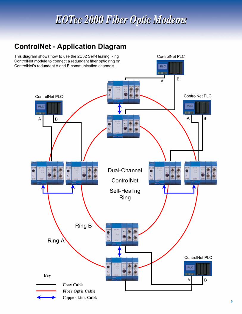
A BKey
Coax Cable
Fiber Optic Cable
Copper Link Cable
Dual-Channel
ControlNet
Self-Healing Ring
Ring A
Ring B
ControlNet-ApplicationDiagram
A B
ControlNet PLC
A B
ControlNet PLC
A B
ControlNet PLC
A B
ControlNet PLC
This diagram shows how to use the C Self-Healing Ring ControlNet module to connect a redundant fiber optic ring on ControlNet's redundant A and B communication channels.
EOTec 2000 Fiber Optic ModemsEOTec 2000 Fiber Optic Modems

0
A Self-Healing Ring (SHR) Module provides fiber media redundancy when utilized in each node or drop of a fiber optic ring-network. The SHR Module detects and redirects data to the secondary fiber path when a break in the fiber occurs between two adjacent nodes. The SHR automatically resets when the fiber path has been restored. Visible LED indicators in conjunction with relay contacts provide local and remote monitoring of the integrity of the fiber optic network.
The configuration of a Self-Healing Ring modem consists of a Power Supply, an Electrical Interface, a Self-Healing Ring Module and two Optical Interface Modules. Inter-module communications and operating power is achieved through the integrated module backplane connections.
ModelNumber 2C30 2C31 2C32
Description SHR for single SHR for dual channel channel ControlNet ControlNet CommunicationsDataRate 9.6K to M Baud 5M Baud 5M Baud
FM Approved Hazardous Locations Certification Class I Division , None None Groups A, B, C & D
CompatibleElectricalC0, C07, C0, ModulesC, C, C5, C0 C0 C9
Self-HealingRingModule
Featuresofthe2C3xmodulesinclude:
- Independent of fiber optic cable size, communications protocol or baud rate- Eliminates down time from fiber failure- Fast network transparent fiber path switching- System diagnostic indicators during operation- Easy add-on upgrade to existing EOTec 000 systems
EOTec 2000 Fiber Optic ModemsEOTec 2000 Fiber Optic Modems
SHR for PLC Networks (except ControlNet,
Profibus and DeviceNet)
StatusIndicatorGreen: Functional Optic Link (Bi-colorLED) Red: Loss of Optical Link RelayContactRating: 75VDC, 0.5A Switching, A Continuous RelayConnection:Pluggable Screw Terminal, to AWG(0.5-.mm), Cage-Clamp AmbientConditions: -0 to 95°C Operational, 0 to 90% Rel. Humidity Non-Condensing
Self Healing Ring Modules - Common Specifications
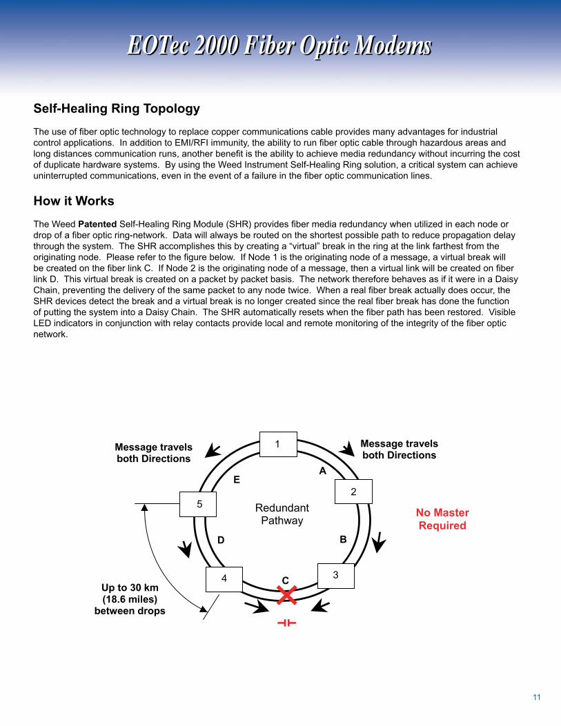
Self-HealingRingTopology
The use of fiber optic technology to replace copper communications cable provides many advantages for industrial control applications. In addition to EMI/RFI immunity, the ability to run fiber optic cable through hazardous areas and long distances communication runs, another benefit is the ability to achieve media redundancy without incurring the cost of duplicate hardware systems. By using the Weed Instrument Self-Healing Ring solution, a critical system can achieve uninterrupted communications, even in the event of a failure in the fiber optic communication lines.
HowitWorks
The Weed Patented Self-Healing Ring Module (SHR) provides fiber media redundancy when utilized in each node or drop of a fiber optic ring-network. Data will always be routed on the shortest possible path to reduce propagation delay through the system. The SHR accomplishes this by creating a “virtual” break in the ring at the link farthest from the originating node. Please refer to the figure below. If Node 1 is the originating node of a message, a virtual break will be created on the fiber link C. If Node 2 is the originating node of a message, then a virtual link will be created on fiber link D. This virtual break is created on a packet by packet basis. The network therefore behaves as if it were in a Daisy Chain, preventing the delivery of the same packet to any node twice. When a real fiber break actually does occur, the SHR devices detect the break and a virtual break is no longer created since the real fiber break has done the function of putting the system into a Daisy Chain. The SHR automatically resets when the fiber path has been restored. Visible LED indicators in conjunction with relay contacts provide local and remote monitoring of the integrity of the fiber optic network.
StatusIndicatorGreen: Functional Optic Link (Bi-colorLED) Red: Loss of Optical Link RelayContactRating: 75VDC, 0.5A Switching, A Continuous RelayConnection:Pluggable Screw Terminal, to AWG(0.5-.mm), Cage-Clamp AmbientConditions: -0 to 95°C Operational, 0 to 90% Rel. Humidity Non-Condensing
EOTec 2000 Fiber Optic ModemsEOTec 2000 Fiber Optic Modems

Optical Interface Modules connect the EOTec 000 modems to the fiber optic cable network, and transfer network data between nodes. Cascade different optical modules in a single modem assembly and optically link modems utilizing 850/00nm optical wavelengths, Multi-mode or Single mode fiber, and SMA or ST* connectors. Two optical modules can be used in one modem to form an optical repeater or to configure an optical daisy chain. Up to five optical modules can be cascaded in one modem to establish an optical star network system. Two optical modules combined with a Self-Healing Ring module provide optical media redundancy in critical applications. A maximum combination of five optical or electrical modules may be connected together in one modem, inter-module communications and operating power is achieved through the integrated module backplane connections.
The basic modem configuration consists of a Power Supply Module, Electrical Interface Module, and an Optical Interface Module.
*ST is a trademark of AT&T
ModelNumber 2E06/2D06 2E07/2D07 2E10/2D10 OpticalWavelength 850nm 850nm 850nm OpticalMode Multi-mode Multi-mode Multi-mode CommunicationsDataRate 9.6K to M Baud 9.6K to M Baud 9.6K to M Baud OpticalPortConnection SMA Compatible ST Compatible ST Compatible dB into 00/0µm db into 00/0µm dB into 6.5/5µm 7dB into 6.5/5µm
DiagnosticOutput D06 only D07 only D0 only4-20mA
OpticalInterfaceModules-CommonFeatures
AmbientConditions: -0 to 85°C Operational, 0 to 95% Rel. Humidity Non-CondensingEmitterType:LEDPowerRequirement(Bus): 9VDC @ 00mA Max per moduleOpticalTransmitIndicator:Green LEDOpticalReceiveIndicator:Amber LEDCertifications: FM Approved Class I, Division , Groups A, B, C & D (selected models only)DiagnosticOutput(2Dxx): -0mAIEC60825-1Class1LEDProducts,FDA21CFR1040.10&1040.11
OpticalInterfaceModules
EOTec 2000 Fiber Optic ModemsEOTec 2000 Fiber Optic Modems
OpticalDynamicRange dB into 00/0µm

2DxxOpticalModuleswith4-20mADiagnosticOutput(xx designates last two digits of Model Numbers) Dxx optical modules provide a full diagnostic output (-0mA). The output is internally powered and is proportional to the received optical power. The output can be monitored and processed continuously in order to insure the integrity of the fiber optic link. This is beneficial for critical applications such as subsea networking where degradation of the optical signals can be detected before a complete loss of communication occurs. An output less than mA indicates loss of optical signal. A pluggable screwterminal connection on the bottom front of the module provides easy access to the output signal.
2E09/2D092E19/2D19 2E36/2D36 2E46/2D46
00nm 00nm 00nm 00nm
Multi-mode Multi-mode Single Mode Single Mode
9.6K to M Baud 9.6K to M Baud 9.6K to M Baud 9.6K to M Baud
ST Compatible ST Compatible ST Compatible ST Compatible
dB into 6.5/5µm 8dB into 6.5/5µm 0dB into 9/5µm 6dB into 9/5µm
D09 only D9 only D6 only D6 only
EOTec 2000 Fiber Optic ModemsEOTec 2000 Fiber Optic Modems

The EOTec Power Supply Modules supply operating power to the EOTec 000 modules. Several different universal modules are available to conform to a wide variety of power sources typically found in industrial control panel applications where wall mounted power supplies are unacceptable. Mix and match to provide the option of "Hot-Swappable" dual power supplies with diagnostic outputs, eliminating "Single Point of Failure" locations in the network.
The basic modem configuration consists of a Power Supply Module, Electrical Interface Module, and an Optical Interface Module.
ModelNumber 2A06/2A16 2A08/2A18 2A56 85 to 0VAC, 50/60Hz, 85 to 0VAC, 50/60Hz, InputPowerRange 50mA VDC ± 0%, 00mA 50mA 85 to 0VDC, 50mA 85 to 0VDC, 50mA OperatingPowerOutput Regulated, 9VDC Regulated, 9VDC Regulated, .A max .A max VDC, 5mA max InputFuseType 00 mA slow-blow 00 mA slow-blow 00 mA slow-blow Fiber Optic Transmitter Compatibility Fiber Optic Receiver (FOT/FOR)
-0 to 85°C Operational -0 to 85°C Operational -0 to 85°C Operational AmbientConditions 0-95% Rel. Humidity 0-95% Rel. Humidity 0-95% Rel. Humidity Non-Condensing Non-Condensing Non-Condensing DiagnosticOutput Form-CRelay A6 only A8 only
PowerSupplyModules
PowerSupplieswithDiagnosticAlarmRelayContacts The A6 and A8 are power supplies with diagnostic alarm relay contacts accessible via screw terminals on the bottom front of the module. Relay Contact Ratings: Form-C, 75VDC, A continuous.
EOTec 2000 Fiber Optic ModemsEOTec 2000 Fiber Optic Modems
Mechanical SpecificationsDouble-width EOTec 000 Modules - A06/A6, A56 Power Supplies, C5/5 Ethernet SwitchesMounting: 5mm DIN RailWeight: <9oz (50g)
ApprovedClassI,Division2
GroupsA,B,C&D
All bus powered All bus powered modules modules

5
Model# ModuleDescription2C02 GE Genius Remote I/O2C07 Reliance R-Net Remote I/O2C10 RS-/852C12 Allen Bradley DH+ & Remote I/O 2C14 Modicon Remote I/O 2C15 Allen Bradley DH-852C20 ControlNet2C21 DeviceNet2C22 Profibus - DP2C29 Modicon Modbus Plus2C30 Self-Healing Ring for PLC networks except ControlNet, DeviceNet, and Profibus2C31 Self-Healing Ring, -CH ControlNet2C32 Self-Healing Ring, -CH ControlNet2E06/2D06 Optical Module2E07/2D07 Optical Module2E09/2D09 Optical Module2E10/2D10 Optical Module2E19/2D19 Optical Module2E36/2D36 Optical Module2E46/2D46 Optical Module2E54 Switched Media Converter 0/00 Base-T2E56 Switched Media Converter 0/00 Base-T2E58 Switched Media Converter 0/00 Base-T2E60 Switched Media Converter 0/00 Base-T2C52 Ethernet Switch 0/00 Mbps
2Txx FOT Analog Link2Rxx FOR Analog Link
2C23 Profibus w/Self-Healing Ring2C53 Ethernet Switch 0/00 Base-T2E55 Switched Media Converter 0/00 Base-T2E57 Switched Media Converter 0/00 Base-T2E59 Switched Media Converter 0/00 Base-T2E61 Switched Media Converter 0/00 Base-T2Mxx Multiplexer2Hxx/2Kxx Multi-Channel CC/Output Module2Sxx/2Pxx Multi-Channel CC/Input Module
EOTec2000PowerSupplySelectionChart(xx designates last two digits of Model numbers)
2A06/2A16 2A08/2A18
OR
OR
2A06/2A16 2A08/2A18
ORExternal24VDC
2A56
OR
Thefollowingmodulescanalsobepoweredfromanominal24VDCsourceviapluggablescrewterminalblocks.Theywillthenprovideoperatingpowertoanybusinterconnectedmodules.
External24VDC
EOTec 2000 Fiber Optic ModemsEOTec 2000 Fiber Optic Modems

6
EOTec 2000 Network TopologiesEOTec 2000 Network Topologies
There are five basic network topologies possible with the EOTec 2000 system. Using these, many combinations can be created. Very similar topologies can be assembled with the other Weed Instrument fiber optic modems, the EOTec 6000.
Point-to-Point Used to make simple connections from a PLC to a PLC or an I/O block.
DaisyChain
Used for multiple drops along a line.
OpticalRepeater Used for strengthening an EOTec optical signal that has traveled the maximum distance throughout a fiber optic cable. It is used for com-municating over very long distanc-es. In addition, this configuration can also convert multi-mode fiber to single mode, and vice versa.
PLC PLC
PLCPLCPLC

7
Star Configuration Used for branching from one point outward. As many as four branches can be made optically. A star system can be connected to another star system if more branches are
required.
Self-HealingRingProvides fiber media redundancy.
-- Indicates fiber optic cable
-- Indicates copper cable
KeyPLC
PLC
PLCPLCPLCPLC
PLC
PLC
PLC
EOTec 2000 Network TopologiesEOTec 2000 Network Topologies

8
The modular EOTec 2000 fiber optic analog data link provides reliable EMI/RFI and lightning immune transmissions of -0mA and 0-0VDC signals over a single fiber optic cable. It is an ideal solution for long run cable problems and has a system accuracy of 0.%. Each transceiver has a single optical port which can be configured for multi-mode or single mode fiber optic cable at 850 nm or 1300 nm using industrialized ST/SMA connectors. LED indicators are provided for Power, Over Range, Under Range and LOCK conditions. The fiber optic receiver (FOR) has additional outputs for signal LOCK and OVER RANGE conditions that can be used to light a remote warning, engage a relay or provide go/no-go information to computer control systems.
The FOT/FOR will accept power from an external VDC source connected directly to a pluggable screw terminal, or from a 0/0VAC power source when using the EOTec A56 Universal Power Supply (shown using both configurations in the photo).
Applications for this device include long distance transmissions, lightning prone areas and transmissions through hazardous areas.
AnalogDataLinks
Fiber Optic Data LinksFiber Optic Data Links
ModelNumber
Wavelength OpticalMode
T06 FOT 0-0VDC 850nm 7dB N/A N/A R06 MM SMA
T07 FOT 0-0VDC 850nm 7dB 5dB N/A R07 MM ST
T09 FOT 0-0VDC 00nm 7dB 5dB N/A R09 MM ST
T0 FOT Hi-power 0-0VDC 850nm dB dB N/A R07 MM ST T FOT -0mA 850nm 7dB N/A N/A R MM SMA
T FOT -0mA 850nm 7dB 5dB N/A R MM ST
T8 FOT -0mA 00nm 7dB 5dB N/A R8 MM ST
T0 FOT Hi-power -0mA 850nm dB dB N/A R MM ST
T6 FOT 0-0VDC 00nm N/A N/A dB R09 SM ST
T6 FOT Hi-power 0-0VDC 00nm N/A N/A 9dB R09 SM ST T7 FOT -0mA 00nm N/A N/A dB R8 SM ST
T9 FOT Hi-power -0mA 00nm N/A N/A 9dB R8 SM ST
R06 FOR 0-0VDC 850nm MM SMA
R07 FOR 0-0VDC 850nm MM ST
R09 FOR 0-0VDC 00nm MM/SM ST
R FOR -0mA 850nm MM SMA
R FOR -0mA 850nm MM ST
R8 FOR -0mA 00nm MM/SM ST
Description*AnalogSignal
FiberConnector
* FOT: Fiber Optic Transmitter FOR: Fiber Optic Receiver
OpticalDynamic
Rangeinto200/230µm
OpticalDynamic
Rangeinto62.5/125µm
MatingReceiver
OpticalDynamic
Rangeinto9/125µm

9
FiberOpticAnalogDataLink-ApplicationDiagram
A56 Power Supply, 85-0VAC, 50/60Hz or 85-5VDC
Accessories
Specifications Analog Data LinksPowerRequirements: to 0VDC at 00mA, or 0/0VAC from A56 Power SupplyInput/OutputSignals: -0mA or 0-0VDCWireCableConnections: De-Pluggable, Cage-Clamp, Screw Terminal, accept to AWGSystemAccuracy(FOT+FOR):± 0.% of span typicalSystemResponseTime(FOT+FOR): < ms (0% to 90% input step change) transfer rates to 800HzAdditionalOutputs(FOR): OVER RANGE, analog signal supplied to transmitter is above normal input range LOCK, turns on when FOR receives adequate light input from fiber 5-0VDC at 5mA, open collectorLEDIndicators: Green - LOCK, receiving adequate optical signal strength from transmitter (FOR) - PWR, power is applied to transmitter (FOT) Amber - OVR, analog input signal at the mated transmitter is above 0VDC/0mA - LOW, analog input signal is below 0VDC/mAAmbientConditions: -0°C to 85°C Operational 0 to 95% Relative Humidity, Non-CondensingMounting: 5mm DIN-RailWeight/Unit: < 9oz (50g)HousingMaterial: Plastic (UL9V-0)
0-0 VDCSignal 9/5µm Single Mode Fiber
Optic Cable up to 60 km distance
2T46FiberOpticTransmitter
(FOT)
2R09FiberOpticReceiver
(FOR)
Dimensions
Features:• No calibration required.• Transmission of 4-20mA or 0-10VDC analog signals over a single fiber optic cable• Configurable with multi-mode or single mode optical fiber• Alarm outputs provided for signal LOCK and OVR (over range) conditions• Available with dual redundant, hot swappable power supplies
PLC
0-0 VDCSignal
-- Indicates fiber optic cable
-- Indicates copper cable
Key
Fiber Optic Data LinksFiber Optic Data Links

0
The EOTec 2000 fiber optic Multi-Channel Contact Closure modules are used to convert up to 0 contact closure inputs (switches, relays, etc.) into fiber optic signals for transmission over a single fiber optic link. Upon activation of the inputs, the receiver module receives the transmitted signals and de-energizes a corresponding, on-board relay operating in a fail-safe mode for switching critical systems.
Each transmit module includes two inputs and is capable of multiplexing up to 0 inputs by cascading additional dual channel input modules. An integrated backplane allows for communications between modules with no external inter-modular connection. Power to all modules is derived from any standard EOTec 000 power supply through the integrated BUS connector or from an external VDC source supplied directly to the transceiver module.
Multi-ChannelContactClosure
Fiber Optic Data LinksFiber Optic Data Links
Description Connector
2S07 -Channel, 850 nm, Multi-mode, Transmitter dB Dry Contact Input ST
2S09 -Channel, 00 nm, Multi-mode, Transmitter dB Dry Contact Input ST
2S10 -Channel, 850 nm, Multi-mode, Transmitter 7 dB Dry Contact Input ST
2S36 -Channel, 00 nm, Single mode, Transmitter 0 dB Dry Contact Input ST
2S46 -Channel, 00 nm, Single mode, Transmitter 6 dB Dry Contact Input ST
2H07 -Channel, 850 nm, Multi-mode Receiver Form C Relay Output ST
2H09 -Channel, 00 nm, Receiver (Multi-mode or Single mode) Form C Relay Output ST
2P02 -Channel Input Module Dry Contact Input N/A
2K02 -Channel Output Module Form C Relay Output N/A
Specifications Multi-Channel Contact ClosurePowerRequirements: 7.5 VDC via the BUS interconnections (from any EOTec 000 power supply module)or to 0VDC @ 00mA, via a pluggable, screw terminal block on the Sxx/Hxx module RelayContactOutput: SPDT Form C relay, via Pluggable Screw Terminal, to AWG(0.5-.mm) Cage-Clamp 60W, 5VA, maximum switching power 0VDC, 50VAC, maximum switching voltage A switching, A carry, maximum current 00,000,000 cycles, minimum operational lifeContactClosureInput: External Dry contacts connected via pluggable, screw terminal blocks Accepts to AWG, 5VDC @ .mA min. contact rating, K ohm max. resistanceLEDStatusIndicators: Power On Green, Ch. A Relay energized/input contact closed Green, Ch. B Relay energized/contact input closed Green, Fiber Transmit - AmberDataUpdateRate: 5mS regardless of the number of channels utilizedAmbientConditions: -0°C to 85°C Operational
ModelNumber
OpticalDynamic
Range
Input/OutputType
Fiber

Multi-ChannelContactClosure-ApplicationDiagram
0/0VAC50/60Hz
or VDC
Up to 0 Dry Contact Inputs (switches, relays, etc.)
Fiber, Single or Multi-mode
Up to 0 Form C Relay Outputs
0/0VAC50/60Hz
or VDC
Features/Benefits:
Modular design for transmitting to 0 contact closure signals
Fail-safe operation
Electrical isolation
Reliable EMI, RFI free communications
Cost-effective, low maintenance installation
Available with dual redundant, hot swappable power supplies
Designed for mounting on standard 5 mm DIN-Rail
Applications:
Safety shutdown systems
Remote transmission over long distances (up to 6 miles)
Transmission through hazardous areas
Alarm event triggering
Fiber Optic Data LinksFiber Optic Data Links
Fiber Optic MultiplexerFiber Optic Multiplexer
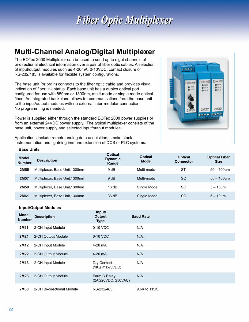
The EOTec 000 Multiplexer can be used to send up to eight channels of bi-directional electrical information over a pair of fiber optic cables. A selection of input/output modules such as -0mA, 0-0VDC, contact closure or RS-232/485 is available for flexible system configurations.
The base unit (or brain) connects to the fiber optic cable and provides visual indication of fiber link status. Each base unit has a duplex optical port configured for use with 850nm or 1300nm, multi-mode or single mode optical fiber. An integrated backplane allows for communications from the base unit to the input/output modules with no external inter-modular connection. No programming is needed.
Power is supplied either through the standard EOTec 000 power supplies or from an external VDC power supply. The typical multiplexer consists of the base unit, power supply and selected input/output modules
Applications include remote analog data acquisition; smoke stack instrumentation and lightning immune extension of DCS or PLC systems.
Multi-ChannelAnalog/DigitalMultiplexer
Description
2M55 Multiplexer, Base Unit,00nm 9 dB Multi-mode ST 50 – 00µm
2M57 Multiplexer, Base Unit,00nm 9 dB Multi-mode SC 50 – 00µm
2M59 Multiplexer, Base Unit,00nm 6 dB Single Mode SC 5 – 0µm
2M61 Multiplexer, Base Unit,00nm 6 dB Single Mode SC 5 – 0µm
ModelNumber
OpticalDynamic
Range
OpticalFiberSize
OpticalMode
OpticalConnector
ModelNumber
DescriptionInput/OutputType
BaudRate
2M11 -CH Input Module 0-0 VDC N/A
2M21 -CH Output Module 0-0 VDC N/A
2M12 -CH Input Module -0 mA N/A
2M22 -CH Output Module -0 mA N/A
2M13 -CH Input Module Dry Contact N/A (KΩ max/5VDC)
2M23 -CH Output Module Form C Relay N/A (A 0VDC, 50VAC)
2M30 -CH Bi-directional Module RS-/85 9.6K to 5K
BaseUnits
Input/OutputModules

Specifications Multiplexer Input/Output Modules
PowerRequirements:7.5 VDC via the BUS interconnections (from A06/6 or A08/8 power supply module) or from an external VDC 00mA max) source, via a pluggable screw terminal block on base unitCopperConnection:Pluggable screw terminal, to AWG (0.5 - .mm) cage clampLEDStatusIndicators:Power On – Green, Ch. A, Ch. B activity - Green, Multiplexer status - Bi-color - Red/Green - Bad/Good DataUpdateRate:<0µS regardless of the number of channels utilizedAmbientConditions:-0 to 85°C Operational, 0-95% RH (Non-condensing)
Transmits up to 8 analog or digital signals over a pair of fiber optic cables
Bi-directional communications
Configurable with multi-mode or single mode optical fiber
Pluggable screw terminals for all wire connections
Visible status LED’s for power, TX/RX and channel inputs
Available with dual redundant, hot swappable power supplies
Designed for mounting on standard 5 mm DIN rail
Dimensions (each module): .5 mm (0.9") w x 99 mm (.9") h x mm (.5") d
Features/Benefits:
FiberOpticMultiplexer-ApplicationDiagram
0-0 VDCSignal 9/5µm Single Mode Fiber
Optic Cable up to 0 km distance
0-0 VDCSignal
FiberOpticMultiplexer
FiberOpticMultiplexer
-- Indicates fiber optic cable
-- Indicates copper cable
Key
RS/85Signal
Dry ContactSignal
-0 mASignal
RS/85Signal
Dry ContactSignal
-0 mASignal
Description
2M55 Multiplexer, Base Unit,00nm 9 dB Multi-mode ST 50 – 00µm
2M57 Multiplexer, Base Unit,00nm 9 dB Multi-mode SC 50 – 00µm
2M59 Multiplexer, Base Unit,00nm 6 dB Single Mode SC 5 – 0µm
2M61 Multiplexer, Base Unit,00nm 6 dB Single Mode SC 5 – 0µm
Fiber Optic MultiplexerFiber Optic Multiplexer

The FOT-CC and FOR-CC Fiber Optic Transmitter/Receiver can be used to transmit contact closure data over long distances. DIN-Rail mount housings enable easy mounting on industry standard hardware. The FOT-CC Transmitter provides a closed contact signal to the FOR-CC Receiver, which activates a Single Pole Double Throw (SPDT) relay. These devices can be used with 50/5 to 00/0 µm fiber optic cable and provide ground loop isolation.
DigitalDataLinks-ContactClosure
Specifications - Digital LinksPower:VDC @ 50 mAOpticalDynamicRange:30dB into 200/230µm fiber, 18dB into 62.5/125µm fiberOpticalWavelength: 850nm multi-mode (standard), 00nm multi-mode and single mode (optional)RelayContactRating(FOR-CC):Maximum Switching Voltage 00VDC, 50VAC, 5A @ 0VDC, 0A @ 5VAC, 6A @ 77VAC (Resistive Load)Connections:Cage-Clamp screw terminals, - AWG (0.5-.mm)Indicators:Green LED - Power, Closed ContactsInput(FOT-CC):Dry contacts, 0 ohms max. contact resistanceAmbientConditions:-0 to 85°C Operational, 0 - 95% Rel. Humidity, Non-condensing
Fiber Optic Data Links Fiber Optic Data Links
Features:
Transmissions up to 5000 meters (6,00 ft)
50/125-200/230 µm fiber optic cable
ST Fiber Connection
Ground Loop Isolation
Fail Safe Operation
DIN - Rail Mount

5
FOT/FOR-CCApplicationDiagram
850nm MM into 00/0 µm > 0dB Dynamic Range00nm MM into 6.5/5 µm > 8dB Dynamic Range
00nm MM into 9/5 µm > dB Dynamic Range
FiberOpticTransmitter(FOT-CC)
FiberOpticReceiver(FOR-CC)
-- Indicates fiber optic cable
-- Indicates copper cable
Key
OEMCustomers• ABB/Westinghouse• GE Nuclear• Siemens
VDC VDC
NC
COM
NO
Form C Relay Output
FOT-CC/FOR-CCSingle-ChannelVersionThe following chart indicates how the output relay contacts will operate on the FOR-CC provided the input contacts on the FOT-CC are wired in fail-safe mode (i.e. input contacts closed in a normal state):
Fiber Optic Data Links Fiber Optic Data Links

6
The EOTec E5-E6 Switched Media Converters provide fiber optic conversion to and from wire based Ethernet. The fiber ports operate at 00Mbps, Full Duplex. The RJ5 ports will auto-negotiate data rates between 0/00 Mbps and Full/Half Duplex operation. These modules will automatically learn the addresses of the devices connected to each port (up to 0) and will buffer and route messages accordingly. There is an additional Ethernet port in the module's integrated BUS, which provides connection for one additional EOTec 000 Ethernet Switch or Switched Media Converter Module, assisting in forming Star or Daisy Chain network configurations.
IndustrialEthernetSwitchedMediaConverters
EOTec 2000 Ethernet ConnectivityEOTec 2000 Ethernet Connectivity
CommonFeatures:2E54-2E63EthernetCompliance:IEEE 80. (U)(X) Compliant, All standard protocolsRJ45PortDataRate:0 or 00Mbps (0/00Base-T(X)), Full or Half Duplex, Automatic wiring correctionPowerIndicator:Green LED - On when proper power is connectedDataIndicator: Green LED - OFF when no connection is detected on port; ON when connection to port established; FLASHING to indicate activity on portPortSpeedIndicator:Amber LED - OFF when data rate is 0Mbps; ON when data rate is 00MbpsAmbientConditions:-0 to 85°C Operational, 5 to 95% Relative Humidity, Non-Condensing Certifications: FM Approved for Class I Division , Groups A, B, C & D (most models)

7
ModelNumber 2C52/2C53 Ethernet Switch Description RJ5 ports bus port PowerRequirements .5W max. 0/00 Base-T Full or Half Duplex IEEE 80. (U)(X) Compliant, All standard protocols Green LED: Off when no connection is detected on port, On when connection to port established, Flashing to indicate activity on port Amber LED: Off when data PortSpeed(RJ45)Indicator rate is 0Mbps, On when data rate is 00Mbps -0 to 85°C Operational 5 to 95% RH, Non-Condensing
IndustrialEthernetSwitch
EOTec 000 Ethernet Switch is an industrially-hardened, DIN-Rail mountable device, which allows you to extend your industrial Ethernet network.
The C5 and C5 0/00 BASE-T Ethernet Switches have four RJ5 twisted pair ports and one BUS port. The integrated BUS port provides a connection for one additional EOTec 000 Ethernet Switch or Switched Media Converter assisting in forming star network configurations. Ethernet switches are unmanaged and require no user configuration. The data rate is automatically negotiated and the ports will auto-sense full or half duplex operation. The switches will automatically learn the addresses of the de-vices connected to each port and will buffer and route messages accordingly.
FM Approved for Class I Division , Groups
A, B, C & D
EthernetModulesareConfigurable to Multiple
Interconnects
Two2E55SwitchedMediaconverters
2E55SwitchedMediaconverterwitha2C53EthernetSwitch
Two2C53EthernetSwitches
PortActivityIndicators
CommunicationsData
EthernetCompliance
AmbientConditions
EOTec 2000 Ethernet ConnectivityEOTec 2000 Ethernet Connectivity

8
ManagedFastEthernetRedundantRingSwitch
Ethernet ConnectivityEthernet Connectivity
The R08 Managed Ring Switch is the ideal solution for redundant systems. The Fast Re-configuration of Networks Topology (FRNT) concept of Weed Instrument offers ultra fast ring re-configuration (30ms) of the network topology and both fault contact and SNMP to provide notification of the ring failure.
The FRNT concept eliminates failures caused by network links and/or switches. Redundancy can be achieved for most types of network topologies, such as Single Ring, Double Rings and Bridged Rings (redundant connections between two rings). A redundant ring topology is a good choice when high availability is needed and when ultra fast re-configuring in case of ring failures is a must. Recovery time of the Redundant Ring is as fast as 0 ms, and network load generated by ring packets is kept on a very low level. The ring is managed by one of the switches (user configured), referred to as the Focal Point (the Root Switch). The other switches in the ring are called member switches.
Configuration of the switches is easy and is done by the user in the Windows based IP Configuration tool. Any of the Ethernet ports can be used. Thus, no serial port is
StandardModelsDescription R208F2-MM-ST-2-W Managed 0/00Mbps Ethernet Ring Switch 6-port RJ45, 2-port fiber, 850 nm, MM, ST R208F2-SM-SC-15-W Managed 0/00Mbps Ethernet Ring Switch 6-port RJ45, 2-port fiber, 1300 nm, SM, SC R208-W Managed 0/00Mbps Ethernet Ring Switch 8-port RJ5
required for setting the IP address or any other configuration parameter on the R208 switch. This means that the R08 can be mounted and installed prior to configuration. Remote configuration and supervision through the network is also possible using the same tool. Communication with the switch itself can also be done by SNMP, and a private MIB is supplied on request, reading inside temperature, HW version, serial number, etc.
Variants:U/R/T07F: 6 TX + FX (MM or SM): MTRJ, LC, SC, STU/R/T08F: 6 TX + FX (MM or SM): MTRJ, LC, SC, STU/R/T08F: 5 TX + FX (MM or SM): MTRJ, LCU/R/T08F: TX + FX (MM or SM): MTRJ, LC U/R/T08F5: TX + 5 FX (MM or SM): MTRJ, LCU/R/T08F6: TX + 6 FX (MM or SM): MTRJ, LCU/R/T08F7: TX + 7 FX (MM or SM): MTRJ, LCU/R/T08F8: 8 FX (MM or SM): MTRJ, LC
PartNumberDescriptions:U08 - Series 00 Unmanaged Switch, eight portsR08 - Series 00 Ring Switch, eight portsT08 - Series 00 Time Sync. Switch, eight portsF - Fiber PortsMM - Multi-modeSM - Single ModeST - ST style connectors for fiber portsSC - SC style connectors for fiber ports - km distance between nodes5 - 5km distance between nodesW - Weed Instrument
Local10/100TXPorts(RJ45)
RingPorts
6
6
6
- 00 FX Multi-mode, ST
- 00 FX Single mode, SC
- 0/00 TX (RJ5)
R208F2-MM-ST-2-W

9
• Free Windows based configuration tool, IPConfig •RealtimeEthernet: -QoS based on layer (IEEE80.p) and layer (IP ToS) -Strict priority scheduling -Head of Line blocking prevention for low priority packets •FRNT: -30ms reconfiguration of redundant ring topology based on the Fast Re-configuration of Network Topology (FRNT) protocol -Up to 00 switches supported in Ring -Most network topologies are supported
•IGMPsnooping -Fully automatic, no separate IGMP server (router) required -Multicast stop filter option -Integration with FRNT for fast multicast filter update in case of topology changes. •SNMP•DHCP
•IPgatewaysupport• True industrial specification -Military Design -Wide temperature range (-0 to +85°C) -Wide DC power range (9 to 60VDC) -No moving parts or electrolytic capacitors -Low power consumption (typically 8-6 W depending on fiber options) -Redundant power inputs -High MTBF numbers •MDX/MDIXtechnology to ease switch connection • User configurable fault contact • Push buttons for port configuration (auto-neg HDX/FDX and 0/00 Mbps) •35mmDIN-Railmounting•19"rackmountingandwallmountingoptions•Options: -VLAN support according IEEE80.D -Security vs. MAC attacks -RSTP and STP
Specifications
InputPower:9 - 60 VDCPowerConsumption(Typ): R08:6W, R08F-MM: 8W, R08F-SM: 8WPowerConsumption(Max): R08:8W, R08F-MM: 0W, R08F-SM: 0WIsolation: 500 VDCAmbientConditions: -0 to 85°C Operational, 5 to 95% Rel. Humidity Non-Condensing Enclosure:IP-0 (Dust Proof)Altitude:to 000mEMC: EN 6000-6- industrial immunity, EN 5008- industrial emission,Vibration: IEC 55-- and -, Class Safety:EN60950Dimensions: (WxHxD) 7mm (8.5") x 88mm (.5") x mm (.9")Weight: 550g (. lbs)
FastEthernetRedundantRing100Mbps
R-208F2-MM
PLC
PLC
PLC
R-208F2-MM
PLC
R-208F2-MM
PLC
RemoteI/O
RemoteI/O
Application:
R-208F2-MM
R-208F2-MM
PLC
PLC
PLC
R-208F2-MM
RemoteI/O
RemoteI/O
RemoteI/O
FastEthernetRedundantRing100Mbps
R-208F2-MM
PLC
PLC
PLC
R-208F2-MM
PLC
PLC
PLC
R-208F2-MM
PLC
R-208F2-MM
PLC
RemoteI/O
RemoteI/O
R-208F2-MM
PLC
RemoteI/O
RemoteI/O
Application:
R-208F2-MMR-208F2-MM
R-208F2-MM
PLC
PLC
PLC
R-208F2-MM
RemoteI/O
RemoteI/O
R-208F2-MM
RemoteI/O
RemoteI/O
RemoteI/O
Camera
Camera
Camera
Features
Ethernet ConnectivityEthernet Connectivity

0
PLCCompatibility:
•ALLEN-BRADLEY •SQUARED•MODICON •WESTINGHOUSE•GEFANUC •RELIANCE•TI/SIEMENS •RS232/422/485
The EOTec 6000 Modular Fiber Optic Modem offers reliable data communication in plant automation sys-tems. This modem has a modular format that offers easy configurability for specific plant networking requirements. Fiber optic modems provide total electrical isolation, eliminating problems with EMI/RFI, lightning, long distances, crosstalk and ground noise. The EOTec 6000 offers greater flexibility and overall cost savings due to its modular, rugged design and proven technology.
The modular modem consists of four basic components: the rack; electrical interface card; optical interface card; and power supply. The EOTec 6000’s flexible modular design allows configuration of the electrical and optical modules for the most cost effective solutions to your industrial communication needs. Each of the basic modules are sold separately. See individual data sheets for more detailed specifications.
EOTec 6000 Fiber Optic ModemsEOTec 6000 Fiber Optic Modems
OverviewIn 99 Weed Instrument acquired from M Corporation the manufacturing/marketing rights to the EOTec line of industrial communications products. Since then, the EOTec 6000 line has been expanded and improved to provide communications with all major brands of PLCs. Applications include industrial process control systems requiring communications between components of the system that may span thousands of feet. Control of the processes may be extremely critical and require highly reliable communications links.

PowerSupplies/Racks
“SY/NET” is a trademark of Square D. “TI Tiway” is a trademark of Texas Instruments. “Westinghouse HPPC” is a trademark of Westinghouse. “Reliance R-Net” is a trademark of Reliance Electric Company.*
Module#-Description
Module#-Description
6C0 - Modicon Remote I/O Compatible, BNC connector
6C0 - GE Fanuc Genius™ I/O Compatible
6C0 - Square D SY/NET™ Compatible
6C0 - Westinghouse HPPC™ Compatible
6C05 - TI Tiway™ Compatible
6C06 - TI 560/565 I/O Compatible
6C07 - Reliance R-Net™ & I/O Compatible
6C09 - Modicon ModbusPlus™
6C0 - RS / Compatible
6C - Modicon Remote I/O Self-Healing Ring Module
6C - Allen Bradley DH+ and I/O Compatible
6C - Modicon Remote I/O Compatible, F connector
6C5 - Allen Bradley DH-85 Compatible
6C6 - RS-85, DB-9 Connector
6C7 - RS-85, F Connector
6C9 - Modicon Modbus Plus™ Compatible ModConnect® certified
6C0 - Self-Healing Ring Master Module
6C - Self-Healing Ring Slave Module
5
ElectricalInterfacesSelf-HealingRingThe EOTec Series 6000 Self-Healing Fiber Optic Modem system provides fault tolerant reliable data communications for plant automation systems. Utilizing the 6C0/6C Master/Slave Modules in a ring configuartion provides for a modular format that is easily configurable for your specific needs.
Power supply modules are available with various input capabilities, as well as a dual redundant power supply.The rack holds the electrical, optical and power supply modules. Each rack can hold one power supply, one electrical interface module and one to four optical or additional electrical interface modules.
6A0 - Power Supply (5 VAC input)
6A0 - Modular Rack
6A0 - Power Supply (0 VAC input)
6A0 - Blank panel for unpopulated rack slots
6A05 - Power Supply (90 to 65 VDC input)
6A06 - Power Supply (0/0 VAC input) UL Approved
6A08 - Power Supply ( VDC)
6A09 - Heavy duty bracket
6A0 - Bracket for 9" Rack Mount
6A8 - Redundant Power Supply ( VDC input)
6A8 - Dual 6A8 Housing
EOTec 6000 Fiber Optic ModemsEOTec 6000 Fiber Optic Modems
OpticalModule
OpticalConnectivity
Wavelength OpticalMode
BaudRate
OpticalDynamicRange
200/230µm
OpticalDynamicRange
62.5/125µm
OpticalDynamicRange
9/125µm
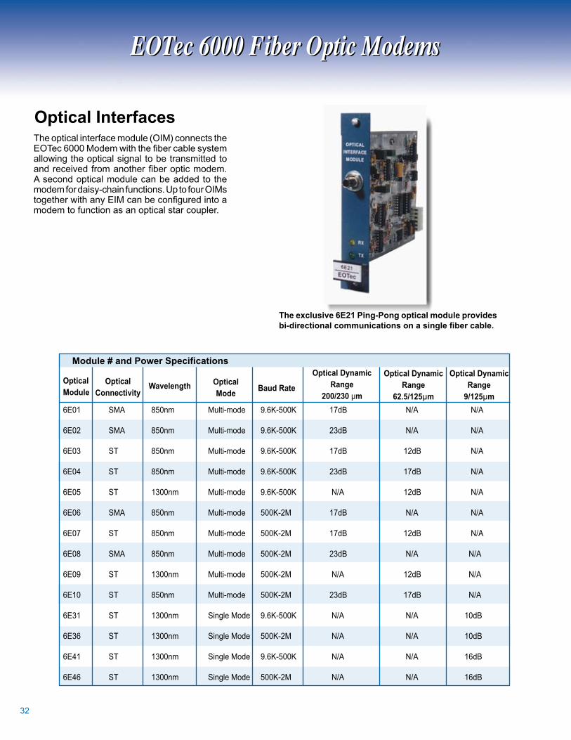
OpticalInterfacesThe optical interface module (OIM) connects the EOTec 6000 Modem with the fiber cable system allowing the optical signal to be transmitted to and received from another fiber optic modem. A second optical module can be added to the modem for daisy-chain functions. Up to four OIMs together with any EIM can be configured into a modem to function as an optical star coupler.
Module # and Power Specifications
Theexclusive6E21Ping-Pongopticalmoduleprovidesbi-directional communications on a single fiber cable.
6E0 SMA 850nm Multi-mode 9.6K-500K 7dB N/A N/A 6E0 SMA 850nm Multi-mode 9.6K-500K dB N/A N/A 6E0 ST 850nm Multi-mode 9.6K-500K 7dB dB N/A 6E0 ST 850nm Multi-mode 9.6K-500K dB 7dB N/A 6E05 ST 00nm Multi-mode 9.6K-500K N/A dB N/A 6E06 SMA 850nm Multi-mode 500K-M 7dB N/A N/A 6E07 ST 850nm Multi-mode 500K-M 7dB dB N/A 6E08 SMA 850nm Multi-mode 500K-M dB N/A N/A 6E09 ST 00nm Multi-mode 500K-M N/A dB N/A 6E0 ST 850nm Multi-mode 500K-M dB 7dB N/A 6E ST 00nm Single Mode 9.6K-500K N/A N/A 0dB 6E6 ST 00nm Single Mode 500K-M N/A N/A 0dB 6E ST 00nm Single Mode 9.6K-500K N/A N/A 6dB 6E6 ST 00nm Single Mode 500K-M N/A N/A 6dB
EOTec 6000 Fiber Optic ModemsEOTec 6000 Fiber Optic Modems

EOTec6000OpticalInterfaceSelectionChart
Op
tica
lIn
terf
ace
ElectricalInterface
EOTec 6000 Fiber Optic ModemsEOTec 6000 Fiber Optic Modems

TrainingSeminarsWeed Fiber Optics provides both on-site training programs as well as comprehensive public seminars on topics ranging from the basics of fiber optic theory and system design to hands-on fiber termination and cable installation training. Training sessions can run from two hours to three days and can be custom designed to meet your specific needs. Training is focused on Instrumentation and Control applications, and is taught by Weed’s experienced staff.
Accessories & ServiceAccessories & Service
TestEquipmentA comprehensive range of specialized fiber optic test equipment is available for either purchase or rental. This equipment includes Optical Time Domain Reflectometers (OTDR), battery-powered Optical Power Meters, light sourc-es, and accessories. Training and on-site support services are available for learning how to use the equipment and for developing customized maintenance and troubleshooting programs.
14
TerminationKitsTermination kits are available for 200/230µm fiber sizes for SMA and ST connectors. The kits are easy to use by plant personnel and do not require epoxy or polishing, thus providing cost-effective installation. Fiber optic jumpers and connectors can also be supplied. These assemblies are extremely rugged to survive harsh plant conditions.

5
CustomEngineeringWeed Instrument design engineers are experts in the fields of fiber optics, multiplexing, signal conditioning, and industrial control system design. If equipment is needed beyond our standard product lines, custom designs or modifications can be provided. The staff also has immediate access to other Weed Instrument experts in temperature and pressure sensing equipment and applications.
FieldSupportHighly experienced technicians and engineers are available to assist in the installation, start-up, maintenance, and troubleshooting of fiber optic systems. They have extensive experience in many types of industrial manufacturing plants and power facility applications and are available for emergency dispatch or scheduled system start-ups. Our staff is equipped with the latest equipment such as OTDRs and digital scopes.
ServicesServices
CustomerServiceTaking care of our customers is priority one for Weed Instrument. We respond to all of their questions and concerns with the greatest respect. We believe it is very important to follow up on every phone call, quote and purchase order for customer satisfaction.
We have the ‘can do’ attitude to make sure our customers are completely confident in choosing our products for their industrial application. If you should need technical questions answered or assistance with installing our products, please contact us, and we will gladly put you in touch with one of our highly experienced Applications Engineers to make sure your questions are answered promptly.
15

6
Weed Instrument works closely with the leading PLC manufacturers to ensure that our fiber optic modems interface properly with their products. We are members of Rockwell Automation's Encompass program, GE-Fanuc's Accompany program, and Schneider Electric's Alliances program.
PLC Manufacturer ProgramsPLC Manufacturer Programs
Rev./006, Pub: RM090055
WeedInstrumentCompany,Inc.707 Jeffrey Way, P.O. Box 00Round Rock, TX 78680-000Toll Free: -800-880-9Phone: (5) -850, Fax: (5) -85E-Mail: [email protected]
Specifications subject to change without notice.
Corporate Profile
Mostmodelsavailableimmediatelyfromstock
Weed Instrument Company is a leading supplier of instrumentation and control equipment for industrial, process and power control applications. Through constant innovation, the company has rapidly expanded since 968 to become a leading supplier of accurate and reliable sensing devices and data communications equipment for harsh industrial environments. Sensing products include temperature sensors, switches and transmitters. Weed Instrument specializes in a wide range of fiber optic and custom products, and provides field support for plant communications,instrumentation, and control applications.
The Fiber Optic division of Weed Instrument was established through acquisition of two pioneering companies in the application of fiber optic technology to the industrial market, EOTec (from 3M) and APEC. Both companies had over ten years of experience in providing fiber optic solutions specific to factory automation and process control. Weed Instrument is continuing this pioneering spirit through such achievements as being the first company to receive FM Approval for fiber optic based products in hazardous areas and developing new technologies such as bi-directional communications over a single fiber.
Our staff is comprised of individuals from the I&C industry, and has a good understanding of the needs and problems specific to industrial applications. We provide complete systems product support including conceptual design, design engineering, manufacturing, testing, field installation, maintenance and calibration. Currently, Weed Instrument Company has manufacturing, testing and engineering facilities located in Round Rock, Texas.
Alliances
Weed Instrument Fiber Optics