Industrial Design Engineering - John Wiley & Sons fileIndustrial Design Engineering October 2008 S....
42
Sources of Innovation You keep it cool... …we keep it clean! 30 oktober 2008 Sybren Jansma s0076139 Paul van Ettinger s0182257
-
Upload
nguyenkiet -
Category
Documents
-
view
212 -
download
0
Transcript of Industrial Design Engineering - John Wiley & Sons fileIndustrial Design Engineering October 2008 S....

Industrial Design Engineering October 2008
S. Jansma & P. van Ettinger University of Twente
Sources of Innovation
You keep it cool...
…we keep it clean!
30 oktober 2008 Sybren Jansma s0076139 Paul van Ettinger s0182257

Industrial Design Engineering October 2008
S. Jansma & P. van Ettinger University of Twente
Sources of Innovation
This design report is directed to the faculty of CTW. University of Twente Industrial Design Engineering Box 217 7500 AE Enschede The Netherlands Telephone number: 053 489 9111 Name Student number Signature Sybren Jansma s0076139 ______________ Paul van Ettinger s0182257 ______________ Course coordinator: dr. A. Reinders Date of publication: 30 October 2008 Number of pages: 42 Number of appendices: 4

Industrial Design Engineering October 2008
S. Jansma & P. van Ettinger University of Twente
Sources of Innovation
Preface
This report is the final design report of an innovative design project of the course “Source of Innovation”. It has been made in a time span of approximately 9 weeks and is written by two students of the Master “Industrial Design Engineering”. The different innovation methods applied in this project are described in chapters 3 until 7. If you are more interested in the final product, chapter 8 gives some high detailed impression and explains the way the product works. The different created collages are detailed represented in the appendices. The authors of this report want to thank prof. J. Halman, prof. S. Kuhlman, J. Stevens, prof. H. Haverlag and dr. A. Reinders for all the valuable and interesting lectures of innovation methods during the courses.
Enschede, 30 oktober 2008
III

Industrial Design Engineering October 2008
S. Jansma & P. van Ettinger
Sources of Innovation
IV
Table of content
Preface .............................................................................................................................................................................................................................................. III Table of content .............................................................................................................................................................................................................................. IV 1 Introduction ................................................................................................................................................................................................................................. 1 2 Preliminary phase ........................................................................................................................................................................................................................ 2 4 The innovation methods ............................................................................................................................................................................................................. 9 5 Innovation journey .................................................................................................................................................................................................................... 10 6 Innovation Phase Model ........................................................................................................................................................................................................... 13 7 Platform Driven Product Development ..................................................................................................................................................................................... 18 8 Innovation Design & Styling ...................................................................................................................................................................................................... 21 9 The product ............................................................................................................................................................................................................................... 24 10 Calculations ............................................................................................................................................................................................................................... 29 Consulted sources ........................................................................................................................................................................................................................... 31 Appendix I Collages.................................................................................................................................................................................................................... 32 Appendix II UVTOP270 ............................................................................................................................................................................................................... 36 Appendix III: Technical drawing ............................................................................................................................................................................................... 37 Appendix IV Luminous efficiency in relation to wavelengths ..................................................................................................................................................... 38

Industrial Design Engineering October 2008
S. Jansma & P. van Ettinger University of Twente
Sources of Innovation
1
1 Introduction In the Master, the course “Sources of Innovation” will give some theories which will be provided on innovation processes and innovation methods. By taking a design project the focus will be on an innovative design of an emerging technology. This innovative development of the product is quite free on condition that there has to make a combination with LED technology. The main goal of this report is to present 4 different innovation methods which were needed to develop a totally new product. In this methods the process will focus on choice there has been made. In the final phase these choice are been summarized in a product description and presented in several pictures. The report is set up as follows. In the first chapter the idea in which field we want to search for our invention. There will be some talking about foodborne illness and different types of surface disinfection. In the second chapter the led technology and possibilities will be further explained. Chapter 3 explains which innovation methods are decided to use and why this choice was made. In the next 4 chapters each of the innovation methods will be described and will be explained by some clear graphs and pictures. In the chapter “The product” there will be a closer look to the product and gives some detailed views. Also the working of the product, just like the internal interfacing between the components. In the last chapter there are made some calculations of the product.

Industrial Design Engineering October 2008
S. Jansma & P. van Ettinger University of Twente
Sources of Innovation
2
2 Preliminary phase The quality of our food becomes better and better. Unfortunately some first-class food will also be rewards with third world hygiene. Yearly between 300.000 and a million people will be the victim of foodborne illness and about 20 till 200 will die. Food poisoning causes some terrible hours of days of feeling pretty sick and weak. Sometimes a visit to the hospital is necessary! We may be very picky in our choice of food in terms of quality, but at the point of hygiene we have less expectation. For example our refrigerator is sometimes a cultivate oasis for different bacteria and pathogens. These types of diseases can be found on food like raw meat, poultry, seafood, eggs, uncooked rice, flour, raw vegetables and salads, also at the time of purchase(picture 1). After purchase, the pathogens can develop tremendously by poor temperature control or spoilage.
Foodborne illness Foodborne illness, commonly called food poisoning are in most cases caused by a variety of already mentioned pathogenic bacteria, viruses and parasites that contaminate food, rather than chemicals or natural toxins. During the incubation period, bacteria pass through the stomach into intestine, attaching to the cells lining the
intestinal walls, and start to multiply there. Some of the pathogens produces toxin, which will absorb into the bloodstream and can directly invade the deeper body tissues. Typical symptoms are vomiting, abdominal cramping, headache and diarrhea which will occur suddenly (within 48 hours) after consuming contaminated food. If the dose of contaminant is high, fever, chills, dehydration and damage to the nervous system may follow. These symptoms may affect a person or a group of people who ate the same food (which called an outbreak). The effect of foodborne illness depends on each person. Some people or age groups are extremely vulnerable, no matter what type of pathogen is involved. These includes: very young children, pregnant women, elderly people and people with a compromised immune system. Also some can become unwell after a small amount of bacteria, while somebody else may remain symptom free after ingesting thousands. The most common foodborne illnesses are: Salmonella (picture 2), Escherichia coli O157:H7 (bacteria), Hepatitis A & B and Norwalk- like virus.
Picture 1: In almost each type of food food poisoning can be arise.
Picture 2: The salmonella bacteria

Industrial Design Engineering October 2008
S. Jansma & P. van Ettinger University of Twente
Sources of Innovation
3
Keeping qualities of food There are different ways to oppose bacteria. Actually you don’t want to eliminate all the bacteria, because some bacteria’s clear away other bacteria. Therefore the main goal is to decrease the amount of bacteria. There are different ways for achieving this goal.
Store cellars, deep-freezing and heating The most common way to store food in the early days is to storage it into a storage cellar. Fresh fruit and vegetables, salted of smoked meat are less sensitive to spoilage and can be preserved here. Cans, dry cookies, biscuits and jam are better to be kept at a storage room; otherwise the humidity can cause spoilage. Food, which is susceptible for bacteria development, can to be stored into a cold environment like a refrigerator to extend its life. Beneath a temperature of 7 or 10 degrees Celsius, the development of bacteria is decreasing. For that reason a refrigerator is set to 4⁰C, to extend the lifetime of fresh food. Nevertheless below 5⁰C there are still some active pathogenic bacteria. Deep-freezing is a solution to get these last active bacteria paralyzed, but then will not be killed. If you do not thaw it in a right way, the bacteria becomes active again and will multiply very quick. That is why you do not freeze it again! When you cook, bake, grill or smoke your food, the majority of the bacteria will be killed. But there are also some vegetables which you do not cook; hence the amount of bacteria is the same. Placing the vegetables in vacuum is a
solution, but then you also have to be sure that the food contains a minimum of bacteria when preserving it. A more old fashioned way is to pickle, salt or sugar food (picture 3). This process provides a difference to the taste of the preserved product as a side effect.
Low frequency radiation UV light decreases the development of bacteria and does this in a relative short time. The horticulture already uses UV-radiation to exterminate insects and bacteria on a large scale. By using the light once a week, the amount of diseases decrease tremendously. The UV penetrates the cellular tissue of the organism and reacts with the DNA. The C=C carbon compound in the molecules of the organism will break down. This causes the cells to die, resulting in a stop to the increase of bacteria. UV is compared to chemical preservation quite safe. There are no harmful chemicals used and the disinfection is immediate. A wavelength of UV-light between 260 -280 nm is the most optimal to oppose the most pathogenic bacteria on different fruits and vegetables.
Picture 3: Salting, pickling and sugar products
Picture 4: Different types of UV lighting devices

Industrial Design Engineering October 2008
S. Jansma & P. van Ettinger University of Twente
Sources of Innovation
4
To this day the most UV -lights are made out of light sources like fluorescent lighting (picture 4). They are relatively big and when they break the mercury toxin will be released and comes into the environment. Also the operating environment is quite an issue, because when the temperature is around the freezing-point, the operating efficiency is decreasing. These lights are mostly used for disinfection in aquariums and in the horticulture. Among the LED technology the UV LED is one the latest inventions. They are a lot smaller then the fluorescent lights and the consumed power is also less. Leds are so small they can be used for air purification devices, cooling systems and in the catering industry. It is proven that elimination of bacteria by radiating of UV rays is more efficient than some other techniques (picture 6 & 7).
By this investigation, it was clear that the market of food conservation is quite interesting. There are many types of conversation methods, but most of them are relatively old. In general the method of conservation is more focused on the decrease of speed of growth and of bacteria. In the latest technologies the focus shifts to the extermination of most of the pathogens. This is why it is interesting to give a closer look to the possibilities of UV light in combination with food conservation. In this report these two interesting search areas will be investigated with the help of four innovation methods. These methods provide an innovative product which gives the consumer the confidence of cleaner food to consume!
Picture 5: Air purification device
20%
55%65%
0%
50%
100%
Washing with tap water for 10 s
Immersion in ozone water of 1 ppm for
one our
Radiating UV rays for 0.5 hour
Re
mo
val r
ate
of
pat
ho
gen
s (%
) Removing perfomance of bateria
Picture 6: Removing performance of bacteria Picture 7: Elemination of micro-organisms by radiation of UV

Industrial Design Engineering October 2008
S. Jansma & P. van Ettinger University of Twente
Sources of Innovation
5
3 LED technology
LED stands for light emitting diode. There are different types on the market, like visible leds which have the output range from red (at a wavelength of approximately 780 nm) till blue-violet (about 400 nm). Leds are not perfectly monochromatic but rather produce wavelengths over a small region of the spectrum. White Led’s are a mixture of all the colors.
LED Led’s come in all sizes and shapes, but the most common are 3mm and 5mm. A led is a semiconductor device and becomes visible for the eye when an electric current passes through it. Picture 8 shows a section view of a white led. They are quite similar to the color led. At the right a drawing of the central placing of the PN junction semiconductor into the reflector cup is to be seen. This reflector cup is placed to gather the light and reflect it toward the epoxy dome lens of the led. The shape of this dome focuses the light into a beam by acting like an inclusion lens. The distance from the cup to the epoxy dome lens determines how tightly it will be focused. There are also Leds on the market with flat or concave lenses which shine the light into a wide or small beam. Aluminium gallium nitride (AlGaN) is used to manufacture the coating for ultraviolet leds into the epoxy dome lens.
UV light Ultraviolet can be divided into four types in the electromagnetic spectrum(picture 9): UV-A (wavelength between 315 and 400 nm) which is the most harmless and is also called “black light”. This type of UV is responsible for skin tanning and used in medicine to treat certain skin disorders. UV-B (wavelength between 280 and 315 nm) is a medium-wave UV and is a dangerous part of light. UV-B is the most harmful UV-range, because it causes sunburns. It's the same as UV-A, but its intensity is much higher.
Picture 8: Light Emitting Diode

Industrial Design Engineering October 2008
S. Jansma & P. van Ettinger University of Twente
Sources of Innovation
6
UV-C is also know as a shortwave UV, and has a wavelength between 200 and 280 nm. Overexposure of this type of radiation causes transient redness of the skin and eye irritation, but doesn’t cause any type of skin cancer. This is because UV-C doesn’t penetrate body surfaces. It has an extremely low penetrating ability. In matter a fact, UV-C is completely stopped by the ordinary eye glasses and by ordinary clothing. Sunlight has a big radiation of UV-C, but the most will be absorbed by the diminishing atmospheric ozone layer.
The last stage of the UV spectrum is called Vacuum-UV and is used for high resolution optics for the cleaning of silicon wafer surfaces. The wavelengths are between 100 en 200 nm and are absorbed by air and therefore it can only be used in a vacuum. From 100 nm the X-ray take it over from the UV. X-ray is used for Rontgen radiation and passes through most substances.
UV disinfection Recent research has shown that commercially available UV-C Led’s are already effective for disinfection of liquids, air and surfaces. The cells of living creatures have their own specific function in the total life cycle. High doses of UV-C radiation will injure the DNA bonds of organic cells. As a result the hereditary of the cell becomes unreadable which results in the death of the cell. The strength of the disinfection depends on two factors: the wavelength and the amount of energy. Around the wavelength of 260nm (short wave) the radiation is the most effective in relation to the disinfection (picture 10). A short exposure time at a high intensity is equal like a long exposure time with a lower intensity. Unfortunately each bacterium needs its own dose of radiation in order to be killed. UV-C disinfection is an effective, eco-friendly and fast method and it applicable into a wide industry.
Picture 9: Range of UV radiation
Picture 10: Optimal wavelength of disinfection

Industrial Design Engineering October 2008
S. Jansma & P. van Ettinger University of Twente
Sources of Innovation
7
UV damaging to polymers The UV-light resistance of damage to plastics depends on three different. These factors are the thickness of the plastic, the opacity and the use of stabilizers. All these factors combined defend the UV light against damaging. UV-A is normally not strong enough to harm plastics. UV-B does the most damage to plastics and UV-C light contains even more damaging energy. How higher the rate of wavelengths, the more damage to plastics will occur. Not all plastics are resistance to UV, like acetal (POM), PC, ABS and PA6/6. These types of plastics are not often used for packaging and have a harmful effect over a longer time to the material. Other plastics like PET, EPS(PS), PP, HDPE, PA11/12, PA6, PES, POP, PBT and PPO are more resistant to UV and the most resistant are PFTE, PVDF, FEP and PEEK™. Polystyrene (PS), which is widely used in food packaging as expand foam, suffers from light-inducted yellowing when exposed to UV-light. This process of discoloration starts when the plastic is exposed to UV over a longer period. The presence of air delays the process. Currently the plastics used in packaging are protected to UV radiation with UV stabilizers, and as a result the plastics will be more resistant to UV-light.
Why and why not LED? To give a short summary, an overview of the benefits of led-technology is necessary. All the issues discussed in the previous sections were quite optimistic, but there are also some disadvantages of LED. Below (table 1 & 2) are the advantages and disadvantages summarized:
Advantage Why? Low power requirement A battery power supply possible for long term use. Minimal heat production High efficient Durable A led has a long life and can function for a very long time. Sometimes the led lives 30 times longer than a normal
bulb light. Size Between 3mm to 5mm, easily to arrange narrow to each other, like on printed circuit boards. Focus ability Because of the small beam angle, it is easy to focus the light on a surface Change-over time The “on” and “off” -time in relation to the full brightness of the led is much faster than i.e. a bulb light. Toxicity In opposition to fluorescent lamp, leds do not have any toxicity fluids, like mercury, in his. Shock resistance The solid design and the strong epoxy dome lens will give less damage after shocks
Table 1: Advantages of LED

Industrial Design Engineering October 2008
S. Jansma & P. van Ettinger University of Twente
Sources of Innovation
8
Disadvantage Why? Expensive Color Led’s are getting cheaper, but in compare with the normal bulb light it has higher purchase cost. UV Leds are
also expensive and there price is given by the wavelength which they give. For example an UV-led with a wavelength of 365 nm is 10 times cheaper than one with a wavelength of 265 nm.
Color quality White leds currently offer a poor quality rendering, due to the combination of three ranges of wavelengths. Also it has a high color temperature.
Ambient temperature Led performance largely depends on the ambient temperature of the operating environment. “Driving” a led “hard” in high ambient temperatures may result in overheating of the led package, eventually leading to device failure.
Table 2: Disadvantages of LED

Industrial Design Engineering October 2008
S. Jansma & P. van Ettinger University of Twente
Sources of Innovation
9
4 The innovation methods To develop the mentioned idea, several innovation methods will be used. Each innovation method gives us detailed information, each in its own way. To make the product innovative, five fields are involved in the product. The first field is the technology in the product which tells us about the types of material, the dynamic processes and the manufacturing processes. The second one gives us a closer look to the field of policies, regulations and societal acceptance, which we indicate with the society field. The marketing field refers to market value, costs and sales and the human factor field looks closer to the usability or interaction between the product and the costumer. Herewith physical ergonomics play a huge role. The last field is het design & styling field. Here the image and appearance of the product will give more attention, because of the competitiveness in the market. In this study the use of the following innovation methods are indicated:
1. Innovation Journey 2. Innovation phase model 3. Platform Driven Product development 4. Innovation Design & Styling
By following this path of innovation methodology, the whole industrial design process is covered. By beginning with the journey, the supporting technology will be examined and the historical aspect of the product becomes clear. With the help of the innovation phase model, the clarification of the task will be sorted out and also the optimization of the elements. In the platform driven product phase, the embodiment of the product becomes clear and there will be a close look to the modularity. During this process the optimization of the lay-out and shape will be supported by the method of design & styling. After this, the focus will be on the details and documentation. In picture 11 the whole innovation process is presented. The different methods have an overlap with each other and it is clear that the whole process of product design is covered. This gives ensures a great control in the innovation a care about that the 5 fields of innovation will be highlighted.
Specifications Task Concept Preliminary layout
Definitive layout
Solution Documentation
Innovation phase model
Innovation Design & Styling Innovation journey
Platform driven product development
Picture 11: Flow chart of the innovation methods

Industrial Design Engineering October 2008
S. Jansma & P. van Ettinger University of Twente
Sources of Innovation
10
5 Innovation journey A process of product development can be seen as a journey of introductions of processes en products to the market. Not every introduction is successful and therefore there will be many setbacks during the journey. An innovation journey can be displayed in a branching model, displaying all innovative processes and products. In the scope of this project, the global innovation journey of led-technology is examined first. The branching model shows only some technological innovations to give an impression of the process. It is impossible to represent all innovations due to the sheer size of all innovations in led-technology.
Led technology journey The model shows the invention of the semiconductor diode(picture 12). The first led is based on the same principles as the diode, but was invented independently. Later on more stable leds were produced but only emitted infrared radiation. From there on the red and later on the color led were produced. Blue led was a created using a slightly different approach and evolved in UV-led amongst others. The OLED is an invention based on electroluminescence and has much potential to evolve more.
Picture 12: Innovation journey of the semiconductor diode technology

Industrial Design Engineering October 2008
S. Jansma & P. van Ettinger University of Twente
Sources of Innovation
11
Much more can be told about the innovation of led-technology and its products. Perhaps illustrating the implementation of leds into products will give an idea of the development of the led. The implementation evolves from the application in calculators and digital watches to traffic signals, led displays and automotive lighting. The main reason for this can be attributed to the efficiency and brightness of the leds. In picture 13 the journey of different types of leds is clearly represented in relation to the luminous efficiency. The latest, and therefore the most interesting, technologies are the OLED, UV-led, the white led and the super bright led. These technologies have the most potential of finding its way to be implemented into a new product.
Food conservation journey The next step is to examine the innovation journey of food conservation. A branching model of the different food conservation methods is made (picture 14). The model goes all the way back to prehistoric times when people started drying food. The journey finds its way along the methods of salting, canning and conserving food in the refrigerator. The relatively new technique of freeze-drying, is actually an ancient method which the Incas already applied. They used to store food in the cold and low pressure environment of the Andes Mountains. This is the same basic principle as used in the modern way of freeze-drying. Other recent conservation methods are UHT-processing and food irradiation. Food irradiation is already applied on a large scale, but is still in development. The conservation method of food irradiation is achieved with the help of x-ray or gamma radiation. The radiation kills some or all harmful bacteria and other pathogens, but also can delay the ripening of fruit.
Picture 13: Journey of different types of leds

Industrial Design Engineering October 2008
S. Jansma & P. van Ettinger University of Twente
Sources of Innovation
12
By combining the journeys of led-technology and food conservation, some directions of innovative products may be created. Examining the two journeys lead to an interesting combination of food irradiation and UV-leds. UV-light also emits waves like x-ray, only at a different wavelength. It is obvious that every type of light emits radiation, but every color emits at a different wavelength. UV-light is closest to x-ray, and therefore possibly the most effective alternative in food irradiation. In addition, UV-light can be generated with the use of LED technology.
Picture 14: Journey of different types of conservation
Industrial Design Engineering October 2008
S. Jansma & P. van Ettinger University of Twente
Sources of Innovation
13
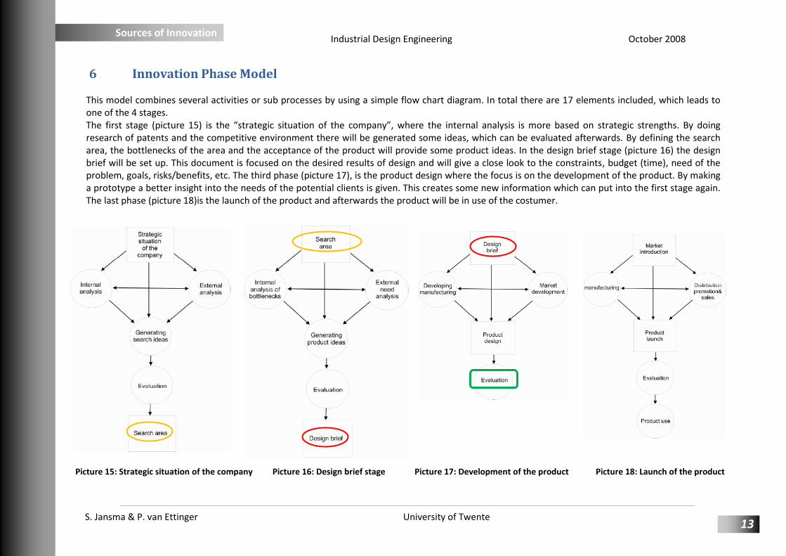
6 Innovation Phase Model This model combines several activities or sub processes by using a simple flow chart diagram. In total there are 17 elements included, which leads to one of the 4 stages. The first stage (picture 15) is the “strategic situation of the company”, where the internal analysis is more based on strategic strengths. By doing research of patents and the competitive environment there will be generated some ideas, which can be evaluated afterwards. By defining the search area, the bottlenecks of the area and the acceptance of the product will provide some product ideas. In the design brief stage (picture 16) the design brief will be set up. This document is focused on the desired results of design and will give a close look to the constraints, budget (time), need of the problem, goals, risks/benefits, etc. The third phase (picture 17), is the product design where the focus is on the development of the product. By making a prototype a better insight into the needs of the potential clients is given. This creates some new information which can put into the first stage again. The last phase (picture 18)is the launch of the product and afterwards the product will be in use of the costumer.
Picture 15: Strategic situation of the company Picture 16: Design brief stage Picture 17: Development of the product Picture 18: Launch of the product

Industrial Design Engineering October 2008
S. Jansma & P. van Ettinger University of Twente
Sources of Innovation
14
Product ideas In a refrigerator fresh meat and vegetables are barely protected against bacteria. Especially chicken is sensitive for example salmonella, which is a dangerous disease for people. The e-coli bacteria are infectious, so when it is in your refrigerator, it spreads itself very fast, what results in more infected food. To fight these bacteria, you can cook or bake it, with the result of the bacteria being killed. Nevertheless some food will not be cooked so the bacteria will still be present there. That is why the idea arises to develop something into a refrigerator which kills the e-coli bacteria. You can do this by UV radiation, which damages the bacteria. Another solution to decrease the amount of diseases is to sort your food in your refrigerator. You can select a layer for your meat and one for all your vegetables. By indicating this layer with a color (like green = vegetables, blue = fish, red = meat), there won’t be any meat right between the vegetables and also gives a structured advantage into your refrigerator. The idea is to use led-technology for food-conserving purposes. UV-light helps in conserving food because it kills bacteria which are exposed to the UV-light. The technology will be implemented in existing refrigerators with an easy installable device. Additionally some leds can be used as ambient lighting inside the refrigerator or indicating different types of food.
Strength The strength of the idea is the dual effect of controlling the e-coli bacteria. The color leds are more an indication to the customer of separating the different types of food. It gives also a better structured look into the refrigerator. In combination with the UV-leds, which eliminates the bacteria, this concept will give the customer the confidence of a clean and clear refrigerator. Other benefits by using UV-leds, in comparison with other UV-devices, are the minimal size, small heat emission and low energy consumption. By using multiple small leds, the UV light will be evenly distributed in the refrigerator. The power for the leds will be supplied by the socket which is already present in ordinary refrigerators. The upcoming led technology is a trend on itself, whereas the old light bulb gradually disappears from the market. The main trend is sustainability and energy consumption, in which the leds consume little energy and lasts longer. Another issue is the world food consumption. The world population is still expanding and feeding everyone is more and more a problem. Implementing the UV-leds will expand the lifespan of the food and therefore more unnecessary waste is avoided. The generation of bacteria will be decreased and therefore the life span of the food will be increased. Also the problem of mixing raw meat and vegetable will be decreased.
Market acceptance The size of the market is wide, but probably only limited to the high-end market for consumer goods. The focus of the product will be aiming for food specialists, older people and young households with little children. For professional use the market will be larger and almost full covering the entire sector. The concept of the idea can be used in cool boxes for example during camp. Also the product can be used on a larger scale, like food processing factories. The stakeholders for this product will be all refrigerator companies, led producers, UV experts, catering companies, consumers and waste disposers.

Industrial Design Engineering October 2008
S. Jansma & P. van Ettinger University of Twente
Sources of Innovation
15
The acceptance of UV-light into a refrigerator can be a problem for the European culture. The harmful side effects of UV radiation to both humanity
and food can be a bottleneck. The effectiveness of the radiation to all products can be an issue in relation to the range of the UV-lights.
Picture 19: Mind map "LED"
Picture 19 shows a mind map of a led. A difference is made between the benefits of the led and its applications. The figure clarifies that the number of advantages is bigger than the disadvantages, which indicates the benefits of led-technology. Looking to the applications, the number of variety is quite large. In our product we examine the applications of UV-light, sphere light and indication lights. Picture 20 presents a mind map of food. In this case there is also made a subdivision in variety, preparation, selling, packaging, presentation and conservation. The focus of our will be on the two last ones sections of presentation and conservation.

Industrial Design Engineering October 2008
S. Jansma & P. van Ettinger University of Twente
Sources of Innovation
16
Picture 20: Mind map "Food"
By getting a summary of the mind maps, the following search fields are defined: Sphere & indication light sources, ultraviolet light/radiation, specific cooling systems and keeping the qualities of food.
It is important to do some patent research in the field where we want to do some innovative development. At the end this will give a clearly defined view of what systems are patented and already exist. The search in this field will focus on ultraviolet light and cooling.

Industrial Design Engineering October 2008
S. Jansma & P. van Ettinger University of Twente
Sources of Innovation
17
Patents In the search of competing products some reasonable patents were found. One patent is about a refrigerator of Matsushita Electric Industrial (patent EP 1 887 297 A1).This refrigerator includes several refrigerating compartments and an integrated light source that is composed of led emitting ultraviolet rays. The ultraviolet rays can inactive the proliferation of microorganisms deposited on the surface of stored food or the wall surface of a storage case. In some of the compartments it is possible to maintain the hygienic conditions, without fading of the products. Without forming of slime and odor, it is possible to keep the inside of storage case clean at all times, which improve the shelf life of food. The imported fact is that this UV-light source device is integrated into the system. In our case the source is modular and compatible; therefore the placement of the devices is not limited to a fixed position. There are a lot of patents which include the air and water purification (within cooling systems). In general there is a patent which says something about surface purification devices and methods (patent US-P 6630031) but this includes a steam-spraying nozzle which sprays a chemical steam upon the surface. By spraying this for about ten seconds it will remove about 90-95% of the pathogens and 99% removal will be accomplished when the spray time will be doubled. Thus in this patent there is nothing said about a UV light source. In the patent US-P 6503464 the UV light source is described. The description says that this type of surface cleaning/ surface processing is used where the processing speed and devices size cannot be attained by any conventional chemical reaction system. Also this device includes a UV lamp. The founded patents gives use the possibility to do something in the food industry with UV radiation and gives a clearly defined product.

Industrial Design Engineering October 2008
S. Jansma & P. van Ettinger University of Twente
Sources of Innovation
18
7 Platform Driven Product Development
An important feature in product development and brand support is platform driven product development. With this method, various related products can be produced relatively fast and cheap. A product platform is a set of subsystems or, in this case, a set of standard components that form a common structure. Out of this platform a stream of related products can be developed and produced. Combining the standard components in a different way can create other product platforms and therefore other product families as well. It is obvious that this method is effective in generating new product ideas for companies, but also trying to reduce costs by means of standardization. The used platform type is the product platform per tool type with common components (also used by Skil). First the architecture of the product is revised to implement this theory (picture 21). The basic components of the product are identified and analyzed to reach a degree of standardization. The standard components are the power supply, UV-module, color led-module, sensor and the CPU. All standard components are designed in a way that they all have interacting interfaces. In this way all components are independent, therefore not every component is needed to reach a functional product. With these components new product platforms are created which are labeled A up to E. These platforms can reach new market segments and as a result expand the production. In addition each product platform can generate numerous of individual products. Examples of products are shown in the diagram and illustrate that within product families also a high differentiation is possible. All this leads to an enormous market potential simply with the help of standard components.
Picture 21: Architecture of product platform

Industrial Design Engineering October 2008
S. Jansma & P. van Ettinger University of Twente
Sources of Innovation
19
The product platforms can be positioned into the market-technology matrix. This matrix indicates the risk of introducing new technology versus the value perception of the customer. In this case the product platforms A up to E are to be seen in the matrix illustrating their properties in this matrix. The product platforms labeled A and B, air and water purification, contain new enabling technology however these type of products already exist. The led-technology and its application are not innovative and also the customer’s value perception will only be considered as that of an improvement. The platform C, food conservation, is a radical new technology in relation to its competing products. The customer will see new benefits for this product, but it is not certain if it will be regarded as a new core product. The reason for this is that the product can be regarded as only an upgrade of the current system, the refrigerator. The application of the showcases, platform D, can provide an improvement to current competing models. The technology is rather basic, but due to its modularity it can be considered as an improvement. The system is easy adjustable to any dimension due to the standard components and it is easy installable, even for in family showcases. Product platform E, the watermark recognition, is a platform with low competitive strength. The customer value perception will be low and only the enabling technology is incremental to existing products. This product is low risk and can maintain short term profitability, possibly in combination with platform D, to support the development of innovative products.
Picture 22: Market-technology matrix

Industrial Design Engineering October 2008
S. Jansma & P. van Ettinger University of Twente
Sources of Innovation
20
It is clear that the product platforms cover a great deal of the market-technology matrix. Also it emphasizes that the food-conservation platform can produce innovative products to expand the category. This product group can ensure the future of the company, but can involve high risk. The more balanced products of platform A, B and D, are interesting for the near future. This innovation method provides us with very helpful tools which can be implemented into the product. The product is set up by different modules, so some of these products can be standardized. The standardized parts can be placed in a module for different purpose. Right now the product is placed in a refrigerator for households. But in the product families there are also possibilities to implement the unit in small cool boxes or bigger cold storages. Subsequently it is necessary to build bigger units, with stronger radiation, to give the same effect at longer ranges an larger areas.

Industrial Design Engineering October 2008
S. Jansma & P. van Ettinger University of Twente
Sources of Innovation
21
8 Innovation Design & Styling Each product has its own image, but when it comes to innovative products, its function is one of the most important things. When we look closer to the function of a product, we can arrange it into different aspects. A good designed product needs no explanation for its function. By looking to the ergonomics of the product, you can reduce the ease of operation, installation and maintenance. Another important aspect is the emotional way your product interacts with the costumer. A good product with high quality, gives a good emotion and affection which gives a positive reputation and assumption. Last but not least the commercial aspect gives more attention to the function of the product. When a product becomes a trade product it will attract more attention. Another advantage is that reusable designed elements save a lot of product development time. In our design & styling method the accent will lie more on the emotional aspect of its function. Due to the harmful UV radiation, the product has to look safe and easy. Also color will give some certain emotions and sense of quality to the costumer.
Certain steps have to be made to achieve an organized way of design and styling innovation. First of all, the product category of relevant products has to be investigated. In this category it is necessary to search for associative products as well as competing products (picture 23 and 24). The associative products in our case are UV-led products, UV-cleaning products, radiation products and other clean or hygienic products. The general idea is that the product has to blend into an existing refrigerator very well and is not regarded as an odd or strange product in its working environment. A visual collage is made with these associative products, as well as a collage with the competing products, refrigerators and an ambiance collage (picture 25 and 26). The next step is generating different sketches of the intended product with these collages in mind. The objective in the beginning of this process is diverging as much as possible to generate many different ideas as possible. Categorizing these ideas will give a better overview of the generated possibilities. In our case we have four different categories. The first category consists of compact round-shaped products that have an upright position in the
Picture 23: Associative product collage
Picture 24: Competing refrigerators collage

Industrial Design Engineering October 2008
S. Jansma & P. van Ettinger University of Twente
Sources of Innovation
22
refrigerator. The second are thin hanging models with a large surface. The third are also hanging products, but smaller and more compact than the second. The last category comprises lamp-like products which are placed upright into the refrigerator. An intermediate functional view to these categories yields, that hanging products are better than the upright ones. First, the upright designs will always claim more room in the refrigerator than the hanging models. Since this is rather a big issue, the preference is given to the hanging products. Another point is that the hanging models are more efficient in respect of the radiated surface of the UV-lights. Radiating from above will cover a greater surface than upright models will do. The next step is converging everything into a few designs that are most appealing. These models are the inspiration of the basic shape of the final product. The second and third categories sketches, with the hanging models, provide the principal inspiration but also the designs of the upright products are kept in mind. A better idea of the products design is generated by diverging again but this time in more specific directions. Now the best layout is examined again with also ergonomic and technical aspects in mind. Creating some variants of the same design will eventually give a well considered basic design of the final product, as seen in the last converging step. This whole process is to see in picture 27. For an enlarged view of all the collages, you will refer to Appendix I.
Picture 25: Refrigerators collage Picture 26: Ambiance collage

Industrial Design Engineering October 2008
S. Jansma & P. van Ettinger University of Twente
Sources of Innovation
23
Picture 27: Diverging, categorizing and converging of the sketches

Industrial Design Engineering October 2008
S. Jansma & P. van Ettinger University of Twente
Sources of Innovation
24
9 The product Here below the final product is shown (picture 28 up to and including 31). This chapter will explain the way the product works and why which choices have been made. In Appendix III there is a technical drawing included.
Picture 28: UV disinfection device with different color ambiences (red, white, blue and green) and placement in refrigerator

Industrial Design Engineering October 2008
S. Jansma & P. van Ettinger University of Twente
Sources of Innovation
25
Picture 29: An UV LED which is integrated in the device (see Appendix II UV TOP270)
Picture 30: Exploded view of the device
Picture 31: UV radiation device with white led

Industrial Design Engineering October 2008
S. Jansma & P. van Ettinger University of Twente
Sources of Innovation
26
Description The devices consist of in total four UV/color led units (three different colors and white) and a unit with the CPU and light sensor(picture 32). In the led unit there are 8 UV leds and 8 color leds. The UV leds have a wavelength of 280 nm and the color leds are tri-chromatic monolithic leds with AlGaInP as material to get a high brightness. The leds radiations overlap each other, so there is a high efficiency of surface radiation (picture 33). At each end of the product there is a suction cup. This is to attach the devices upon a glass plate. There is also an opportunity to attach it to a rack, which is common in old types of refrigerators. Also the CPU & sensor device will be secured with two suction naps. The power supply from UV radiation device to power devices is by means of wires with little suction cups. These cups can be placed in the walls and corners of the refrigerator. The final embodiment of the product is attached to other sterile products. The color white indicates of a sterile environment and the closed, smooth and small shape does not attract human attention. In current refrigerators the light source is controlled an end-switch. By closing the door a switch will be compressed. In most chases this switch can be locked, so the there is continues supply of energy. In our case this is necessary, because energy has to be delivered when the refrigerator is opened (color led) en when it is closed (UV led). The connection between the devices and the power consumption is by means of the fitting which is already present in a refrigerator. By mounting the fitting, it is quite easy to connect the devices and there is no need for additional supplies.
Picture 33: Overlap of radiation
Picture 32: Device for sensor and CPU

Industrial Design Engineering October 2008
S. Jansma & P. van Ettinger University of Twente
Sources of Innovation
27
050
100150200250300
5 10 15 20 25 30 35 40 45 50 55 60
Wav
ele
ngt
h (n
m)
Minuten (min)
Interval UV radiation
The way it works Two different types of leds are included in the product. The UV leds take part of the disinfection of the surface on the product and the color leds gives an indicated structure on each surface which they radiate to. The leds have their own contribution in the whole process, therefore they work separately. In table 3 it is clarified that when the door of the refrigerator is open, only the color leds are on, and gives a structured look into your refrigerator. By avoiding danger of expose of UV radiation, the UV leds are off when the door is open. When the sensor indicated that the door opens, it shuts down the UV leds immediately so there is no radiation danger to the health of the user. While the door of the refrigerator is closed, the UV radiation takes place. Because the wavelength of 280 nm decreases the growth of bacteria, it does not mean that the product itself is safe for this light. If the food, like cauliflower or lettuce is radiated for a continued long time, it gives yellowness to the food or gives other kinds of food damage. Because of this high dose (280nm) the expose time has to be short as well. Radiating when the door is closed gives higher energy consumption, consequently increasing the energy costs. Already mentioned, some packaging can resist UV radiation for
a long time. That is why the radiation will take place in intervals. After closing the door, the UV radiation takes place for about 5 minutes. Right then, the UV radiation stops and starts again after 15 minutes. So in a cycle of one hour, there will be 3 times 5 minutes UV
radiation (picture 34).
UV LED Color LED
Refrigerator is open
OFF ON
Refrigerator is closed
ON (interval) OFF
Table 3: Working combination LED's
Picture 34: Interval UV radiation

Industrial Design Engineering October 2008
S. Jansma & P. van Ettinger University of Twente
Sources of Innovation
28
Sensor & CPU Because our device has different functions that do not cooperate at the same time, a sensor is needed. When the refrigerator is closed, the ultraviolet source has to be active. The color leds are inactive at that time, because they are not needed at that moment. When our device is in the refrigerator and the door is closed, it is total dark inside. By opening it, there is always a difference between total dark and some light of an external light source (room light, daylight, etc.), that gives you a view into the refrigerator. By using a very sensitive light sensor the difference of opening and closing of the refrigerator can be indicated. The APSD-9002 (picture 35) is a low-cost analog-output ambient light photo with a miniature chip led leas-free surface mount package. The phototransistor peaks in human luminosity curve. This type of sensor is often used in mobile applications, like PDA, televisions and camera’s. Because of his excellent response, the various light sources can be detected with low sensitivity. This is also when the environment temperature is below zero degree Celsius, because is temperature performance is in a range of -40°C to 85°C. When we give a look to our performance temperature, which is approximately between 0°C and 10°C, the minimal required photocurrent is about 0,75W (picture 36). The energy supply (V) of this sensor lies between 2.4 and 5.5 V. The type of light which will fall upon the sensor can be daylight, but also artificial light emitting devices. This gives us the opportunity to use it by day and by night, where daylight and room light is needed. The sensor will be placed in a different device than the actual UV/color led devices. In this device is also a CPU present, which takes care of the interface between the sensor and the leds.
Picture 35: APDS-9002 Miniature Surface-Mount Ambient Light
Picture 36: Relation between photocurrent and temperature

Industrial Design Engineering October 2008
S. Jansma & P. van Ettinger University of Twente
Sources of Innovation
29
10 Calculations
Calculation lumination on surface refrigerator The beam angle of the color led is 120°. The maximum distance upon the surface is 200mm. With this we can calculate the total illuminated surface (picture 37):
tan α = BC
AB
BC = 346,41mm = r
r2 ∙ π = Total illuminated surface A = 𝟎, 𝟑𝟖𝐦𝟐
To give a good indication of a surface in the refrigerator, the color leds has to have a certain amount of illumination. The amount of illumination can be classified within a range from one till 100.000l ux. A full moon is around 1 lux, street lighting 10 lux and home lighting between 30-300 lux. For this device there will be need an illumination of about 20 lux. This is not too strong, but strong enough to give a colorful atmosphere.
𝐸 =𝐼
𝑑2→ 𝐼 = 20 𝑙𝑚/𝑚2 ∙ 0,22 = 0,8𝑐𝑑
Because the radiation isn’t on one meter but at 200mm, the ratio is:
20 𝑙𝑢𝑥 ∙ 0,38𝑚2 = 𝟕, 𝟔 𝒍𝒖𝒎 at 200 mm on a surface of 0,38m2 At a wavelength of 555nm, the range of a green LED, the strength of current is approximately 1,464 mW.
Picture 37: Beam angle

Industrial Design Engineering October 2008
S. Jansma & P. van Ettinger University of Twente
Sources of Innovation
30
In Appendix IV the values of luminous efficiency in relation to the wavelength is displayed. These values are needed to derive the strength of current for each color led.
Blue (470 nm) → 0.011
0,09098= 0,12𝑊
Green (555 nm) → 7,6lum ∙ 1,464 ∙ 10−3 = 0,011W
Red (650 nm) → 0,011
0,107= 0,1W
Because the device contains 8 color leds in total, the maximum amount of current becomes: 8 ∙ 0,12𝑊 = 0,96 = 𝟏𝑾 The total power consumption of one device is 1W for 8 color leds and for 8 UV leds it becomes 1,2 W (=8x 150 mW -> Appendix II). The needed power consumption of a standard refrigerator light bulb is 15W. So in our case it is possible to use up to 14 separate devices, it account the sensor and CPU also uses some of the power.

Industrial Design Engineering October 2008
S. Jansma & P. van Ettinger University of Twente
Sources of Innovation
31
Consulted sources Patents (www.freepatentsonline.com) 1. Konjima, Y; Ashida, Y; Hirota, Y; Ishita, M (Matsushita Electric Co., Inc), Refrigerator, JP, EP188297A1, 24 May 2006, Appl. EP20060756551, 13 Feb.
2008 2. Miki, N and Nitta, T; Surface purification apparatus and surface purification method, Tokyo, JP, US-P6630031, 12 Oct. 2003, Appl. 09/417009, 7 Oct.
2003 3. Miki, N and Nitta, T; Ultravioletprocessing apparatus and ultraviolet processing method, US-P6503464, 12 Nov. 1999, Appl. 09/416415, 7 Jan. 2003
Digital sources Nakamura, S; Fasol, G; Pearton, S.J; The Blue Laser Diode: The Complete Story, Springer Verlag, 2nd Edition (October 2, 2000)
LEDs move into the ultraviolet, 17 May. 2006, http://www.physicsworld.com, Sept. 2008
Zheludev, N., "The life and times of the LED — a 100-year history" (PDF). Nature Photonics 1 (4): 189–192. doi:10.1038/nphoton.2007.34.
Ghaffar, UV Damage to polymers, Website, 1976. http://www.gcrio.org/UNEP1998/UNEP98p62.html, Sept. 2008.
Lupu, Alexandra, "UV Radiation – What UVA, UVB and UVC Rays Are and How They Affect Us". Seasonal Discomforts. Softpedia, 9 sept. 2008
Johns, W.E, “Notes on LEDs”, website, 2003. http://www.gizmology.net/LEDs.htm, Sept 2008.
Gezondheid NV, “Versheid van voedingsproducten”, Website, http://www.gezondheid.be/index.cfm?fuseaction=art&art id=123
"UV protection plastics", (Zeus Industrial Products, Inc.), 2005

Industrial Design Engineering October 2008
S. Jansma & P. van Ettinger University of Twente
Sources of Innovation
32
Appendix I Collages

Industrial Design Engineering October 2008
S. Jansma & P. van Ettinger University of Twente
Sources of Innovation
33

Industrial Design Engineering October 2008
S. Jansma & P. van Ettinger University of Twente
Sources of Innovation
34

Industrial Design Engineering October 2008
S. Jansma & P. van Ettinger University of Twente
Sources of Innovation
35

Industrial Design Engineering October 2008
S. Jansma & P. van Ettinger University of Twente
Sources of Innovation
36
Appendix II UVTOP270

Industrial Design Engineering October 2008
S. Jansma & P. van Ettinger University of Twente
Sources of Innovation
37
Appendix III: Technical drawing

Industrial Design Engineering October 2008
S. Jansma & P. van Ettinger University of Twente
Sources of Innovation
38
Appendix IV Luminous efficiency in relation to wavelengths