Inductive Interface for ERGM GPS Guided Projectile ... · 1 NDIA Guns and Missile Systems 28 March...
18
1 NDIA Guns and Missile Systems 28 March 2006 Inductive Interface for ERGM GPS Guided Projectile – Background and Test Results NDIA Gun & Missile Systems Conference Sacremento, CA 27 – 30 March, 2006 George Wiles Naval Surface Warfare Center, Dahlgren VA (540) 653-6904, [email protected]
Transcript of Inductive Interface for ERGM GPS Guided Projectile ... · 1 NDIA Guns and Missile Systems 28 March...

1NDIA Guns and Missile Systems
28 March 2006
Inductive Interface for ERGM GPS Guided Projectile – Background and Test Results
NDIA Gun & Missile Systems ConferenceSacremento, CA 27 – 30 March, 2006
George WilesNaval Surface Warfare Center, Dahlgren VA
(540) 653-6904, [email protected]

2NDIA Guns and Missile Systems
28 March 2006
ERGM Flight Sequence
MotorBurn
GPSAcquisition
Window
Battery On Fins Deploy
Initialization
Canards DeployRoll Control
If GPS Jammed, Inertial Guidance to Target
TerminalManeuver
Establish Glide Slope

3NDIA Guns and Missile Systems
28 March 2006
Mk45 Mod 4 5”/62 Gun
• Improved for Extended Range Projectiles and High Energy Propelling Charge
New Inductive Setter for Guided Projectiles

4NDIA Guns and Missile Systems
28 March 2006
Driving Requirements
• ERGM is stored as a wooden round. To ready for flight:
– Perform self test– Transfer target and Ownship information– Load GPS cryptokeys– Prepare GPS for fast acquisition
• Similar process to other GPS weapons, except:
– No umbilical– No GPS lock prior to launch– Harsh gun environment
• Must be done in minimal time to allow for high rate of fire.

5NDIA Guns and Missile Systems
28 March 2006
Data Communication Interface Requirements
• Gun System Rate Of Fire Dependent On ERGM Initialization Time.
• Support GPS Hot Start / Direct P(Y) acquisition:– Special data and time pulse
requirements.– Adhere to NSA guidelines for
crypto.• Requirement derived from
historical Mk34 Fuze Setter Requirement.
• High Rate of Fire allows for Multiple Round Simultaneous Impact (MRSI)
Max ERGM Rate of Fire
4
5
6
7
8
9
10
1 2 3 4 5 6 7 8 9 10
ERGM Initialization Time (Sec.)
Rate
of
Fir
e (
rnd
/m
in)
55 Deg Elv
Threshold
Source: BAE

6NDIA Guns and Missile Systems
28 March 2006
Data Communication Interface Concept
GPSReference Receiver
ER
GM
Time Reference
Source
Data formatand control
Data coil
Power coil
Crypto
EP2 Panel
Fire Control System
Ship’s GPS Antenna Setter
Hood

7NDIA Guns and Missile Systems
28 March 2006
DCI Overview
• Provides power and two way serial communication via a dual coil design.
• Power:– 20 kHz 50% duty cycle power waveform.– Designed for 80 Watts (60 W spec, 44 W
typical in practice).• Data:
– 500 kHz Manchester encoded data.– Gun is Master / ERGM is Slave.– Cyclic Redundancy Check (CRC) on all
data except Crypto.– Crypto message block, is checked for
proper size.– Analysis indicates bit error rate (BER) of
0.02% needed for rate of fire timeline.

8NDIA Guns and Missile Systems
28 March 2006
Mission Data Overview
• 30,000 bits defined in WS33710. Smaller subset of those deemed required for ERGM initialization.
• Data contents:– Target location (repeated back for safety)– Warhead mode (HOB or point detonate)– Ship’s own position, velocity– Gun bearing, elevation, muzzle velocity estimate.– GPS Ephemeris and Crypto variables– Time of Day– Time of arrival (only required for MRSI)– GPS Almanac (not required)– Meteorological data
• Surface winds, air temp, pressure (not required)• Winds aloft (not required)
– Preplanned Waypoints (reserved for future use)
9NDIA Guns and Missile Systems
28 March 2006
GPS Hot Start Drives Interface Design
• A typical GPS receiver can perform a cold start:– Acquire C/A code (unencrypted, 1 msec repeat).– Demodulate GPS data stream (12.5 minutes).– Pull time of day from data stream.– Handover to P(Y) encrypted military signal.– Triangulate own position.
• A hot start can occur when the receiver has been previously tracking or is initialized with current data.– Known time of day (to a few tenths of a millisecond).– Known last position (to nearest kilometer).– Data stream content (ephemeris for all satellites in view).– Directly acquire P(Y) code.
ERGM interface designed to provide all data necessary to allow round to perform a hot start
Exceeds ERGM flight time.
Direct Y required by performance spec

10NDIA Guns and Missile Systems
28 March 2006
DCI Output Voltage Regulation Shown to Perform Beyond Limits of Expected Misalignments
Misalignment Testing
16
11.6
11.0
13.0
11.3
10.7
12.7
10.9
12.4
10.4
9.7
11.5
9.39
1616
13.2
10.3
8.1
9 9
8
9
10
11
12
13
14
15
16
Min Load Typ Load Max LoadPCU Load
DC
I Out
put V
olta
ge
Upper Spec Limit
No Offset
0.125" Tilted Misalignment
0.125" Vertical Misalignment
0.250" Tilted Misalignment
0.250" Vertical misalignment
Lower Spec Limit
TiltMisalignment
VerticalMisalignment

11NDIA Guns and Missile Systems
28 March 2006
Time Mark Jitter
• Time Mark Pulse – provides time and frequency reference:– Aligned to GPS Time “1 second
rollover” to within 1 microsecond – (no decimal places in time field beyond “tenths” required).
– Interleaved with data. Gun plans for a break in data every 1/10 second to allow pulse to come thru.
– Low jitter (+/- 50 nsec) requires local pulse source (difficult requirement for ship system to meet).
Example of jitter testing with prototype hood and coils
+/- 50 nsec requirement

12NDIA Guns and Missile Systems
28 March 2006
Initialization Timeline
BIT
SAASM POST
OSCILLATOR CALIBRATION
PROJECTILE READY STATUS
GUN
MISSIONCOMPUTER
GPSRECEIVER
DATA HOLDBATTERY
MCRESET
GUN-ERGMTALK
KEYSSENT
SQUIBDHB
READYTO FIRE
0 1 2 3
= PULSE =DATA
KEY PROCESSING
MISSION DATA COLLECTED
DHB RISE
PROJECTILEREADY
6 Sec
Gun System Firing TimelineLoad
Carousel Lower Hood
Initialize Round Raise Hood
Rotate Carousel
Ram Round & Prop Charge Fire

13NDIA Guns and Missile Systems
28 March 2006
Recent Testing
• Dec 2005• Mk45 Mod 4
Prototype Gun• Potomac River
Test Range, Dahlgren, VA
• Combined effort with BAE and Raytheon participation
14NDIA Guns and Missile Systems
28 March 2006
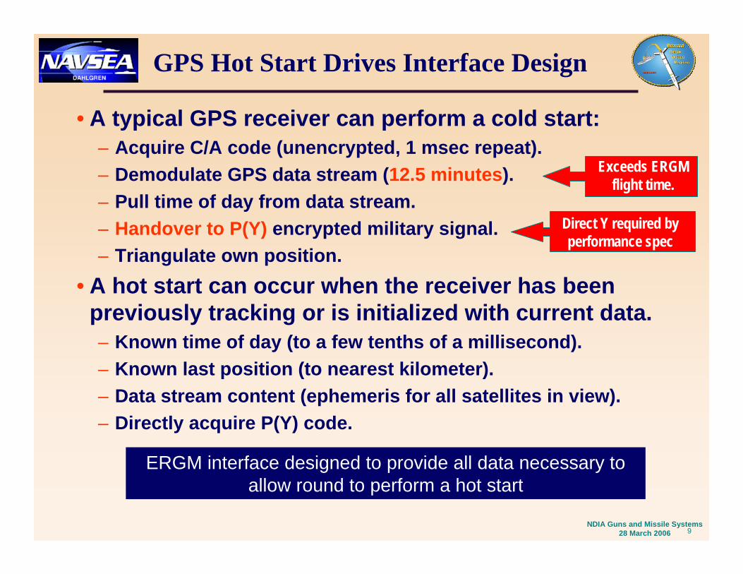
Data Communication Test
• ERGM In Loader Drum Environment With EP2 Tactical Software.• Testing Conducted With Stand Alone ERGM And With PTS For
Diagnostic Analysis.
Blue denotes tactical configurationBlue denotes tactical configuration

15NDIA Guns and Missile Systems
28 March 2006
Data Communications Testing Results
• Repeatedly Achieved Projectile Ready Status In Less Than 3 Seconds.– Average Initialization Time Of
2.6 Seconds. – Successfully Demonstrated
13 RequirementsIncluding Proper Time Transfer, OscillatorCalibration, Mission Data, Crypto Loading, Data Hold.
– Verified Successful Initialization And Oscillator Cal With Direct-Y GPS Acquisition Post Data Hold Period.
ERGM Setting Times
0
0.5
1
1.5
2
2.5
3
3.5
4
0 5 10 15 20 25 30 35 40 45 50 55
Cycle
Seco
nds
Live Data Hold Battery Installed
AUR Test cable installed
AUR Test cable removed
16NDIA Guns and Missile Systems
28 March 2006
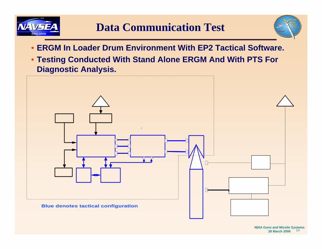
Clock Calibration
• Allocation for clock calibration at Initialization Station is 0.1 parts per million (PPM).
• Procedure: Initialize round, put into standby, acquire GPS, compare known freq offset (post track) and calibrated freq offset.
Demonstrated Calibration in parts per million
0
1
2
3
4
5
6
7
8
0 - 0.
025
0.025
-0.050
.050-.
075
.075-.
100
.100-.
125
.125-.
150
.150-.
175
.175-.
200
.200-.
225
Tria
ls
All but one of the trials with > 0.1 sec error had a standby time of 125 seconds. Additional error can be attributed to clock oscillator drift (also within allocation)

17NDIA Guns and Missile Systems
28 March 2006
Initialization Time
• Majority of sets occurred within 3 seconds. • Investigation of “flyers” is underway.• Cycle with Data Hold Battery Squib event exceeded goal by
0.1 second (expected and allowed).
Demonstrated Initialization Time
0
1
2
3
4
5
6
2.57 2.67 2.77 2.87 2.97 3.07 3.17 3.27 3.37 3.47 3.57 3.67
Seconds
Tria
ls Data Hold Battery Squib
3 sec
ond r
eqmt

18NDIA Guns and Missile Systems
28 March 2006
Conclusions
• Solid technological advancement in state of the art in inductive setting.
• Demonstrated compliance with all requirements.• Low risk to move forward to operational system
testing.
• Thanks to Raytheon (Texas Instruments) and BAE (United Defense LP) for many years of innovation, cooperation and dedication. Its been a long time coming!