INDUCTION MOTOR CONTROLLER USING FUZZY LOGIC NOR...
37
INDUCTION MOTOR CONTROLLER USING FUZZY LOGIC NOR AIZILA BINTI GOREP A project report submitted in partial Fulfillment of the requirement for the award of the Degree of Master of Electrical & Electronic Engineering Faculty of Electrical & Electronic Engineering Universiti Tun Hussien Onn Malaysia JANUARI 2013
Transcript of INDUCTION MOTOR CONTROLLER USING FUZZY LOGIC NOR...

INDUCTION MOTOR CONTROLLER USING FUZZY LOGIC
NOR AIZILA BINTI GOREP
A project report submitted in partial
Fulfillment of the requirement for the award of the
Degree of Master of Electrical & Electronic Engineering
Faculty of Electrical & Electronic Engineering
Universiti Tun Hussien Onn Malaysia
JANUARI 2013

iv
ABSTRACT
Induction Motor is widely used in general industry applications focusing on
production area. Induction motor speed control is becoming very important due to
increase the profit to the industries with increase efficiency, reliability and
performance of induction motor. Due to the problem facing in induction motor that
require complex mathematical model and varying parameters, Fuzzy Logic
Controller (FLC) is applied to overcome this problem. The FLC based on the
concepts of an artificial intelligence and attractive alternatives method to tackle the
problem of controller design for complex mathematical model of system. This
project used FLC Sugeno types. The purpose used FLC is to control speed and
increase the efficiency of IM. While, the conventional controller only works well for
linear system and their performances will decrease for nonlinear system. To make an
induction motor operates such as Direct Current (DC) motor, Field Oriented Control
(FOC) drives is applied for Induction Motor drive. FOC also offering a fast dynamic
response and a high precision ability for IM drive. This project is implemented using
Simulink Matlab. Based on the test results show the response of the speed curve
takes less time to settle and reach the desired value.

v
ABSTRAK
Induction Motor (IM) sangat meluas penggunaanya umumnya dalam bidang industri
dengan tumpuan lebih kepada industri pembuatan. Pengawalan kelajuan motor
aruhan menjadi penting bagi tujuan meningkatkan keuntungan dalam industri dengan
cara meningkatkan kecekapan, kebolehpercayaan kebolehgunaan dan prestasi motor
aruhan tersebut. Disebabkan masalah yang dihadapi dalam motor aruhan yang
memerlukan model matematik yang kompleks dan pelbagai parameter, Fuzzy Logic
Controller (FLC) digunakan untuk mengatasi masalah ini. FLC adalah berdasarkan
konsep kecerdasan tiruan dan merupakan satu kaedah alternatif yang menarik untuk
menangani masalah reka bentuk pengawal bagi model matematik yang kompleks.
Projek ini menggunakan FLC jenis Sugeno. Tujuan penggunaan FLC adalah untuk
mengawal kelajuan dan meningkatkan kecekapan IM. Lagi pula penggunaan
pengawal konvensional terhad pada pengawal yang menggunakan sistem kawalan
linear dan keupayaan pengawal menjadi berkurang apabila sistem kawalan bukan
linear diaplikasi padanya. Bagi memastikan IM beroperasi seperti motor Direct
Current (DC), Field Oriented Control (FOC) digunakan sebagai pemacu IM. FOC
juga menawarkan tindakbalas dinamik yang cepat dan keupayaan ketepatan
pemacuan IM. Projek ini dilaksanakan dengan menggunakan Matlab Simulink.
Berdasarkan keputusan ujian menunjukkan lengkungan laju mengambil masa yang
kurang untuk selesai dan mencapai nilai yang diingini.

vi
CONTENTS
CHAPTER ITEM
THESIS STATUS APPROVAL
DECLARATION
ACKNOWLEDGEMENT
ABSTRACT
ABSTRAK
CONTENTS
LIST OF TABLES
LIST OF FIGURES
LIST OF TERMINOLOGY
PAGE
i
ii
iii
iv
v
vi
x
xi
xiii
CHAPTER 1 INTRODUCTION 1
1.1 Project Background 1
1.2 Problem Statements 2
1.3 Project Objectives 3
1.4 Project Scopes 3
1.5 Report Outline 4
CHAPTER 2 LITERATURE REVIEW 5

vii
2.1 Induction Motor Theory and Design 5
2.1.1 Speed Control of Induction
Motor
2.1.2 Induction Motor Dynamic
Model
7
8
2.2 Field Oriented Control
2.3 Sugeno Fuzzy Logic
Controller
2.3.1 Fuzzy Rule Based System
2.3.2 Construction of Fuzzy Models
2.3.3 Mathematics Expression of the
S Fuzzy Model
2.4 Matlab Overview
2.5 Various Controller Method
2.5.1 Propotional Integral Controller
(PI)
2.5.2 Genetic Algorithm Controller
(GAs)
2.5.3 Neural Network Controller (NN)
2.6 Various Speed Control
2.6.1 Direct Torque Control
2.6.2 Scalar Control (v/f control)
2.7 Description of Previous Method
8
10
11
12
12
14
15
15
16
19
20
20
21
22
CHAPTER 3 METHODOLOGY 24
3.1 Introduction of Methods Used in This
Project
24

viii
3.2
3.3
3.4
3.5
3.6
3.7
Induction Motor Modelling
Design Controller
Apply FOC Method for Induction
Motor
DQ Transformation for FOC
Fuzzy Logic Controller Design
Conclusion
26
27
28
28
33
35
36
36
37
37
37
38
39
40
41
42
43
45
49
49
CHAPTER 4 DEVELOPMENT OF SIMULINK MODEL
4.1
4.2
4.3
4.4
4.5
Fuzzy Logic Design for Induction Motor
Membership Function Design
4.2.1 Input Linguistik Variable
4.2.2 Fuzzy Set and MFs for Input
Variable Speed Error (e)
4.2.3 Fuzzy Set and MFs for Input
Variable Change in Speed Error
(∆e)
4.2.4 Output Numerical Variable
Rule Base Design for the Output (ɷsl)
Design of Fuzzy Logic Controller Using
MATLAB
4.4.1 Ruled Based Used for Fuzzy
Logic Controller
4.4.2 Program for Designing the
Fuzzy Logic Controller
4.4.3 FIS Editor
Induction Motor Simulink Model
4.5.1 ABC-DQ and DQ-ABC Block

ix
4.6
4.5.2 Rotor Flux Calculation Block
4.5.3 Stator Quadrature-axis
Calculation Block
4.5.4 Induction Motor Drive Data
4.5.5 FOC with FLC of IM
MATLAB/SIMULINK Block
Diagram Design.
Conclusion
50
50
51
52
57
CHAPTER 5 RESULT, ANALYSIS AND DISCUSSION 58
58
58
59
60
60
61
61
62
5.1
5.2
5.3
Result
5.1.1 Output for Input Voltage
5.1.2 Output for Stator Current
5.1.3 Output for Rotor Speed
5.1.4 Output for the Electromagnetic
Torque
Discussion
5.2.1 Comparison Between Sugeno and
Mamdani Method
Conclusion
CHAPTER 6 CONCLUSION AND RECOMMENDATION 63
63 6.1 Conclusion
6.2 Recommendation 63
65 REFERENCES
APPENDIX

x
LIST OF TABLES
1 Fuzzy Sets and the respective membership function
for speed error 38
2 Fuzzy Sets and the respective membership function
for change in speed error 39
3 Fuzzy Sets and the respective membership function
For change of speed control 40
4 Fuzzy rule table for output (wsl) 41
5 Asynchronous Machine SI Unit Parameter 52

xi
LIST OF FIGURES
2.1 Wound rotor construction 6
2.2 Squirrel cage construction 6
2.3 Field Oriented Control Block Diagram 10
2.4 Fuzzy Rule based system 11
2.6 Basic Block of PI Controller 16
2.7 Flowchart of genetic algorithm 18
2.8 Neural Fuzzy network ANFIS configuration 19
2.9 Overview of key competing VFD control platform 20
2.10 Change in stator flux 21
2.11 Control loop of an AC drive with frequency control using
PWM 22
3.1 Block diagram of fuzzy FOC controller of IM 25
3.2 Induction motor modeling method controller design 26
3.3 Controller design 27
3.4 αβγ transform as applied to three symmetrical currents 30
3.5 The three phase current lag their corresponding phase
voltages by δ 30
3.6 dqo transform as applied to the stator of a synchronous
Machine 31
3.7 A (d,q) coordinate system with orthogonal components
along d (direct) and q (quadrature) axes 32
3.8 Example Block diagram of Indirect FOC 33
3.9 Configuration of a pure fuzzy system 34
4.1 FIS editor rules window in Matlab 45
4.2 Membership function for input error (e) 46
xii
4.3 Membership function for input change error (∆e) 46
4.4 Membership function for output change of control (e) 47
4.5 Rule viewer with inputs e=0 and Δe=0 47
4.6 Surface Viewer of the Fuzzy Logic Rules Base 48
4.7(a) Conversions between abc and dq reference block 49
4.7(b) Conversions between abc and dq reference block 50
4.8 Flux calculation block 50
4.9 Stator quadrature-axis of induction motor 51
4.10 Block inside FOC 53
4.11 Space vector model of Induction motor 54
4.12 Design of fuzzy logic block 55
4.13 Block diagram of FOC IM with FLC 56
5.1(a) Output for input voltage 58
5.1(b) Output for input voltage 59
5.2(a) Output for stator current 59
5.2(b) Output for stator current 59
5.3(a) Output for rotor speed 60
5.3(b) Output for rotor speed 60
5.4(a) Output for the electromagnetic torque 60
5.4(b) Output for the electromagnetic torque 61

xiii
LIST OF TERMINOLOGY
AC Alternated Current
IM induction motor
FOC Field Oriented Control
FLC Fuzzy Logic Controller
S Sugeno
FIS Fuzzy Inference System
VFD Variable Frequency Drive
PWM Pulse Width Modulator
IMC Induction Motor Control
SCIM structure to give the overall Squirrel Cage Induction Motor
v/f Volts per Hertz
DTC Direct Torque Control
MIN Minimum
DSC Direct Self-Control
SVM Space Vector Modulation
NEG Negative
POS Positive.
MUX Multiplexer
DE-MUX Demultiplexer,
d-q direct-quadrature

CHAPTER 1
INTRODUCTION
1.1 Project Background
An induction motor (IM) is an asynchronous Alternated Current (AC) motor where
power is transferred to the motor by electromagnetic induction. It is much like
transformer action. An induction motor has an advantage like simplicity, reliability,
low cost and virtually maintenance-free electrical drives. It also characterized by
highly common-linear, complex and time varying dynamics and inaccessibility of
some of the states and outputs for measurements [1]. It can be considered as a
challenging engineering problem.
Variable speed motors help improve efficiency and reduce noise. There are
various speed control techniques available like:
1. Direct control torque control
2. Vector Control
3. Volts/Hertz control scheme
4. Field Oriented Control
There are many others that can apply then listing above. In this project the
induction motor speed control applies is Field Oriented Control (FOC) [2]. It is
because their ability to achieving high performance control of induction motor
drives.

2
Previously the speed controls of Induction Motor are traditionally using fixed
gain PI and PID controllers. However their sensitivity to parameter variations loads
disturbances become their disadvantaged. Their disadvantaged can be solved using
adaptive control technic such as self-turning PI controller. The design for the
controller required the exact system mathematical model. Because of that an accurate
mathematical modelling that depends unavoidable parameter variation need to be
considered. The growing of Fuzzy control systems has sparked a flurry of activities
in the analysis and design of fuzzy logic system.
Fuzzy logic approach allows the designer to handle efficiently very complex
closed-loop control problems, reducing in many cases, engineering time and cost. It
has the ability to distribute gain over a range of inputs in order to avoid the saturation
of the control capability. Fuzzy logic shoved very useful to solved nonlinear control
problems. It’s also allows a simpler and more robust control solution whose
performance can only be matched by a classical controller with adaptive
characteristics. The advantages provided by a FLC is it operates in a knowledge –
based way and its knowledge relies on a set of linguistic such as if-then rules like a
human logic.
1.2 Problem Statements
In manufacturing nowadays the problem that manufactures always want to avoid is
low efficiency and reduced cost. Because of that many manufactures are turning to
variable speed motor technology to help increase efficiency, reduce noise and cut
cost in product design. One of the focuses for energy efficiency is to control the
motor speed. The good control in motor speed is important to achieve maximum
torque and efficiency. The very overwhelmingly applications in industrial
applications and for commercial and domestics application is AC motors. For solved
that problem or reduces that problem AC induction motor were choose because of
the distinct advantages over other types of motor. For that purpose Field oriented
Control (FOC) techniques were used to control the motor flux and decompose the
AC motor into torque producing component. The usual method of computation of
mathematical model of the system is difficult. Fuzzy logic implements human logic

3
thinking into control system and more similar to human logic. For this case fuzzy
learning used to enhanced speed control of an indirect FOC induction motor drive is
proposed such that the machine can follow references model to achieve desired
speed performance. FOC and Fuzzy logic controller were investigated.
1.3 Project Objectives
The major objective of this research is to improve performances of Induction Motor
by developed fuzzy logic controller to control the speed of the Induction Motor. Its
measurable objectives are as follows:
a) To derive mathematical model of Induction Motor.
b) To propose FOC method for induction motor.
c) To developed fuzzy logic controller based on Sugeno.
d) To investigate Sugeno fuzzy logic controller for control the speed of Induction
Motor.
1.4 Project Scopes
This project is primarily concerned to the speed control of an IM. The scopes of this
project are:
a) The IM variable that will control is the speed.
b) The IM use has input voltage 240- 460V.
c) Field Oriented Control (FOC) is used to control the motor flux.
d) The controller apply is fuzzy logic controller with Sugeno scheme.
e) The voltage and frequency input to the IM are to be controlled to obtain the
desired speed response.

4
1.5 Report Outline
This project deals with the proposed idea of a fuzzy controller for a closed loop
speed control of an induction motor. FOC control method is used for the speed
control of the Induction Motor. This report is divided into six chapters. Chapter 1 is
an introduction and gives an overview of the project and speaks about the scope and
the main objective. Chapter 2 discusses briefly about the induction motor and scalar
speed control or V/f control of the induction motor. Chapter 3 discuss a method
used. It includes FOC, IM and fuzzy logic. Chapter 4 gives an overview of the fuzzy
logic. It discusses about the fuzzy sets, their operation and membership functions. It
also provides the design of the controller based on Sugeno architecture. Chapter 5 is
dedicated to the simulation of the induction motor speed control system in
MATLAB/SIMULINK®. The results obtained have been compared and discussed.
Where is at Chapter 6 include conclusion and also includes information about the
future scope of the designed controller.

5
CHAPTER 2
LITERATURE REVIEW
2.1 Induction Motor Theory and Design
An Induction Motor (IM) widely used in industry because of the advantages that it
have.
IM have two main parts:
a) Stator
b) Rotor
The stator is the outer body of the motor which houses the driven windings
on an iron core. It’s made with aluminium or cast iron arranged up of a stack of
round pre-punched laminations pressed into the frame. By the way the stator
windings are arranged, the magnetic field appears to synchronously rotate
electrically around the inside of the motor housing.
Rotor is a cylinder made from round laminations pressed onto the motor shaft
and have a number of short-circuited winding. The rotor is built around a shaft,
which transmits the mechanical power to the load. The rotor is equipped with
cooling fins. At the back, there is another bearing and a cooling fan affixed to the
rotor.Two types of construction are utilized for the rotor [3]:
a) Wound-rotor
b) Squirrel-cage rotor

6
A wound rotor is made of many turns of insulated wire and is connected to
the slip ring on the motor shaft. The wound rotor IM is used primarily to start a high
inertia load or a load that requires a very high starting torque across the full speed
range.
Figure 2.1: Wound Rotor Construction
Squirrel-cage rotor consists of a cylindrical laminated core with parallel slots
for carrying the rotor conductors. It is not wires, but thick, heavy bars of copper,
aluminums or its alloys. The conductor bars are inserted from one end of the rotor
and as one bar in each slot. There are end rings which are welded or electrically
braced or even bolted at both ends of the rotor, thus maintaining electrical continuity.
These end rings are short-circuited. It looks similar to a squirrel cage.
Figure 2.2: Squirrel Cage Construction

7
2.1.1 Speed Control of Induction Motor
Motor speed can be changed because the torque curve of the motor is effectively
modified by the amount of resistance connect to rotor circuit. The speeds of
maximum torque decrease if the values of resistance increase. Basically, by reducing
the load will cause the motor to speed up and increasing the load will cause the
motor to slow down until the load and motor torque are equal. When the load and
torque are equal the slip losses are dissipated in secondary resistor. That causes the
speed regulation and net efficiency poor.
The number of poles and frequency determines the speed of the IM. It can be
proved with the formulae of a synchronous speed [4]:
( )
Where N equal to speed in RPM, f is applied frequency in Hz and P is the number of
magnetic poles.The difference between the synchronous speed and the full-load
motor speed is called slip, S which is normally expressed in percent. Ns is
synchronous spedd and Nr is rotor speed. The equation can be written as:
( )

8
2.1.2 Induction Motor Dynamic Model
The IM were run with MATLAB/SIMULINK® program running under three phase
sinusoidal symmetrical excitation. Synchronous frame is used where
a) Stator frame where =
b) Rotor frame where =
c) Synchronous frame associated with frequency (conceivably time varying) of
the stator excitation.
d) Rotor flux frame in which the d-axis lines up with the direction of the rotor
flux vector.
denotes the rotational speed or angular frequency of a frame (in electrical
rad/s) with respect to the stationary rotor. The angular position is obtained by
integrating speed over time. That is the choice of the common d-q frame is usually
prescribed by the symmetry constraints levied by the construction and excitation of
the machine [5].
∫ (2.3)
2.2 Field Oriented Control (FOC)
FOC is a very popular control technique use to control the IM applications. FOC also
called Vector control. Vector control is a Variable Frequency Drive (VFD) control
method which controls three-phase AC electric motor output by means of three
controllable VFD inverter output variables such as:
a) Voltage magnitude
b) Voltage angle
c) Frequency.

9
AC drives that use Pulse Width Modulator (PWM) techniques have varying
levels of performance based on control algorithms. There are four basic types of
control for AC drives today. These are:
a) Volts per Hertz
b) Sensor less Vector Control
c) Flux Vector Control
d) Field Oriented Control.
Volts/Hertz control is a basic control method, providing a variable frequency
drive for applications like fan and pump. It provides fair speed and starting torque, at
a reasonable cost. Sensor less vector control provides better speed regulation and the
ability to produce a high starting torque. Flux vector control provides more precise
speed and torque control with dynamic response. Field Oriented Control drives
provide the best speed and torque regulation available for AC motors [6]. It provides
DC like performance for AC motors, and is well suited for typical DC applications.
In this cases FOC is chosen because it capability to combine with Fuzzy logic
controller. It’s also has an ability to separate and independently control (or regulate)
the motor flux and torque [7].
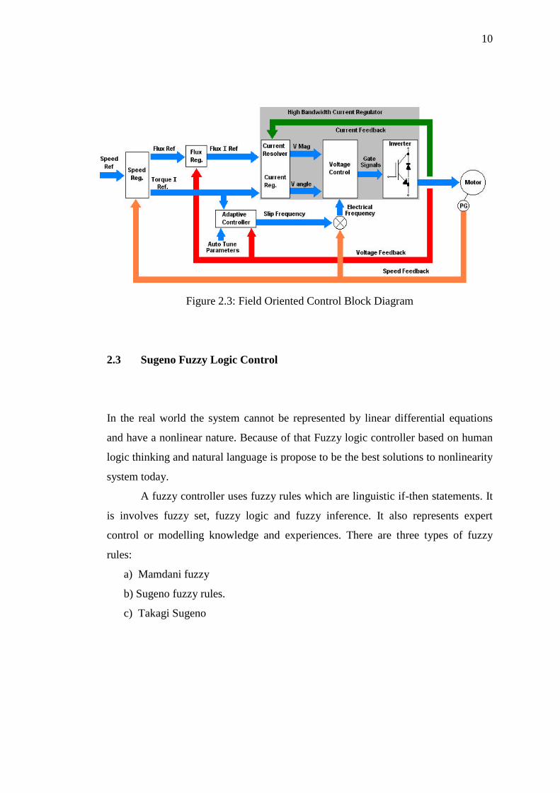
Figure 2.3 show block diagram of FOC. A high bandwidth current regulator
that separates and controls the components of stator current replaces the volts/hertz
core. The high bandwidth characteristics of this control help eliminate nuisance trips
due to shock-loads and will continuously adapt to changes in the motor and load
characteristics. A separate adaptive controller uses information gained during auto
tuning, actual reference information, and motor feedback information to give
independent torque and flux control. This allows continuous regulation of the motor
speed and torque. Also notice that Force Technology generates separate flux and
torque references to improve the overall control of those quantities.
10
Figure 2.3: Field Oriented Control Block Diagram
2.3 Sugeno Fuzzy Logic Control
In the real world the system cannot be represented by linear differential equations
and have a nonlinear nature. Because of that Fuzzy logic controller based on human
logic thinking and natural language is propose to be the best solutions to nonlinearity
system today.
A fuzzy controller uses fuzzy rules which are linguistic if-then statements. It
is involves fuzzy set, fuzzy logic and fuzzy inference. It also represents expert
control or modelling knowledge and experiences. There are three types of fuzzy
rules:
a) Mamdani fuzzy
b) Sugeno fuzzy rules.
c) Takagi Sugeno

11
2.3.1 Fuzzy Rule Based System
Fuzzy rule based system consists of 5 conventional blocks. They are built to solve a
complex problem. It show in figure 2.4.
Figure 2.4: Fuzzy Rule Based System
Every block has their own function. Here list down 5 conventional blocks
with their function:
a) A rule-base containing a number of fuzzy if-then rules
b) A database which defines the membership functions of the fuzzy sets used in
the fuzzy rule.
c) A decision-making unit which per- forms the inference operations on the rules
d) A fuzzification interface which transform the crisp inputs into degrees of
match with linguistic values
e) A de-fuzziffication interface which transform the fuzzy results of the inference
into a crisp output.

12
2.3.2 Construction of Fuzzy Models
To design an S fuzzy controller, an S fuzzy model for a nonlinear system is needed.
Therefore the construction of a fuzzy model represents an important and basic
procedure in this approach [8]. Generally there are two approaches for constructing
fuzzy models:
a) Identification (fuzzy modelling) using input-output data
b) Derivation from given nonlinear system equations.
c) Identification (fuzzy modelling) using input-output data mainly consist of
two parts:
i) Structure identification
ii) Parameter identifications.
2.3.3 Mathematics Expression of the S Fuzzy Model
S fuzzy model consist of R rules where the i-th rule can be represented as:
.,,2,1 .,,2,1
then
is and,, is , is if : Rule
2211
,,22
,11
21
jj
qiq
iii
kimm
kiki
rkRi
xaxaxay
AzAzAzi m
(2.4)
It also described the parameter varying systems which possess m
working state characteristic variables, q inputs and single output. R is the number
of rules in the S fuzzy model. z j mj 1 2, , , is the j-th characteristic
variable, which reflects the working state of the systems. It can be selected as input,
output or other variables that affecting the parameters of system dynamics.
x l ql 1 2, , , is the l-th model input. y
i
is the output of the i-th rule.

13
For the i-th rule, jki
jA,
is the kj -th fuzzy subset of z j . a
l
i
is the
coefficient of the consequent. r j is the fuzzy partition number of z j . For simplicity
of induction, r rj and r is determined by both the complexity and the accuracy
of the model.
Once a set of working state variables z z zm10 20 0
, , , and model input
variables x x xq10 20 0
, , , are available, then the output of the S model under such
working states is calculated by the weighted-average of each yi
:
y yi i
i
Ri
i
R
1 1
(2.5)
Where, yi
is determined by consequent equation of the i-th rule. The truth-
value i of the i-th rule is determined with below equation:
i
j
m
j
i k
jA z
j
1
0,
(2.6)
Furthermore, equation (2.7) can be rewritten as:
y a x a xi i
i
Ri
q
i
q
i
Ri
i
R
1 1
1 1 1
(2.7)
Equation (2.7) illustrated that the S fuzzy model can be expressed as an
ordinary linear equation under certain working states since the truth-value i
is
only determined by the working state variables. As i
varies with working state, S
fuzzy model is a coefficient-varying linear equation. For all possible varying ranges
of working states, the S fuzzy model reflects the relationships between model
parameters and working states. Therefore, the global dynamic characteristics of the
parameter varying systems can be represented.

14
2.4 Matlab Overview
Matlab originally wrote by Dr Cleve Moler, Chief scientist at MathWorks, Inc. The
purpose of Matlab development is to use in courses in matrix theory, linear algebra
and numerical analysis. The first version was written in the late 1970s.
Matlab is a high-performance technical computing language. Typical Matlab
are used for:
a) Math and computation
b) Algorithm development
c) Data analysis
d) Exploration
e) Visualization
f) Modelling, simulation and prototyping
g) Scientific and engineering graphics
h) Application development, including graphical user interface building and etc.
Matlab also has both an environment and programming language. Matlab
also allows user to build own reusable tools known as M-files. Since the M-files can
be open it is easy to modify the M-files. One of the main features of Matlab are used
in this project is a two and three dimensional graphics for plotting and displaying
data and ability to cooperate with programs written in other languages and for
importing and exporting formatted data.
The major usable for Matlab in this project is a SIMULINK. SIMULINK
include in a Matlab toolbox for the dynamic simulation of linear and nonlinear
systems. Matlab toolboxes consist of:
a) Signal processing-contains function to design analogue and digital filters and
apply these filters to data and analyse the results.
b) Image processing-Provide access to a wide variety of functions for reading,
writing and filtering images of various kinds in different ways.
c) Control system-Provides several features for advanced control system design
and analysis.
d) Optimization-Contains basic tools for use in constrained and unconstrained
minimization problems.
e) Neural networks-Allows you to simulate neural networks.
15
f) Communications-Provides functions to model the components of a
communication systems physical layer.
g) Robust control-Allows users to create robust multivariable feedback control
system design based on the concept of the singular value Bode plot.
h) Statistics-Include a wide variety of system analysis tools for varying data.
i) Splines-Used to find approximate functional representations of data sets.
j) Simulink-Allow users to model dynamic systems graphically.
k) Fuzzy logic-Allows for manipulation of fuzzy systems and membership
functions.
This project required the optimized used of Matlab to achieve the desired
output. That why Matlab becomes one of the powerful software.
2.5 Various Controller Method
There is much controller method design to achieve the optimum control evaluable
use to Induction Motor. Recent controller that have been used such as:
a) Fuzzy Logic Controller (FLC)
b) Proportional Integral Controller (PI)
c) Genetic Algorithm Controller (GAs)
d) Neural Network Controller (NN)
Fuzzy Logic Controller is a main focus in this project. FLC is applied to keep
the motor speed to be constant when the load varies. In this section FLC is not to be
discussing because it already discuss in chapter 4 briefly.
2.5.1 Proportional Integral Controller (PI)
Proportional Integral Controller (PI) is a very classic controller. It can be used for
high applications in the electric motor drive. The motor-control is traditionally
handled by fixed-gain PI controller. However, the fixed-gain controllers are very

16
sensitive to such as parameter variation, load and disturbances. This is because the
controller parameter has to be continually adapted or tuned.
Figure 2.7 shows basic block diagram of PI controller.
Figure 2.6: Basic block of PI Controller
PI controller is a feedback controller. PI drives the plant to be controlled with
comparison between the output and desire set point and the integral of that value. PI
controller can reduce steady state error to zero. The derivation action makes the
system steadier in steady state in case of noisy.
2.5.2 Genetic Algorithm Controller (GAs)
This project does not use Genetic Algorithm Controller (GAs). For study purpose
GAs controller were discuss here. It is because one of the famous controller
developments today is Genetic Algorithm Controller (Gas). GA successful applies in
optimization technique based on the mechanism of natural selection. Recently GA is
recognized as an effective and efficient technique to solve optimization problems. It
can produce better performances compare to PI controller.
GA concept is to survival of the fittest. The founders of GAs were first
suggested by John Holland and his colleagues in 1975. The main operators of GA
are selection, reproduction and mutation. It works with a population of solution
SP +
e(t)
∑
_
PV
𝑃 𝐾𝑝 ∗ 𝑒(𝑡)
𝐼 𝐾𝑖 𝑒(𝜏)𝑑𝜏
+
MV
∑
+
Process

17
called chromosomes. Fitness of each chromosome is determined by evaluating it
against an objective function.
The main operators of GA are selection that represents initial generation. Its
begin by randomly generating an initial population of the long real-valued strings.
Selections direct the search of GAs toward the best individual. Reproduction is a
process by which parent structures are selected to form new offspring. For the
mutation the breeder genetic algorithm is used to implement the mutation operator
for the real-coded GA which uses a nonlinear term for the distribution of mutation
range applied to gene values. This mutation algorithm is able to generate most point
in the hypercube defined by the variables of the individual and range of the mutation.
Figure 2.7 shows flowchart of Genetic Algorithm. This algorithm is repeated
for many generations and finally stops when reaching individuals that represent the
optimum solution for the problem. The algorithm different from more traditional
search and optimization methods [9]. The optimization methods are listed below:
a) GA searches a population of point in parallel instead of searching for a single
point.
b) GA does not require auxiliary knowledge even require derivative
information. The objective function and corresponding fitness levels
influence the direction of search.
c) The GA method used probabilistic transition rules.
d) The nature of the functions being optimized is immaterial.
The main operation of GA is the selection, crossover and mutation. Its allows
the creation of new individuals which may be better than their parents.

18
Figure 2.7: Flowchart of Genetic Algorithm
Code the parameters
Initial Population
Calculating Fitness
Decision
Selection
Crossover
Mutation
End
Y
N

19
2.5.3 Neural Network Controller (NN)
One of the controller method designs is neural networks controllers (NN). ANN’s
also are potential candidates for approximating complex non-linear process
dynamics and have been used to formulate a variety of control strategies [10]. There
are two basic design approaches:
a) Direct design
b) Indirect design
Direct design is when the neural network is itself the controller. The most
fundamental method is termed direct inverse control. It uses a trained inverse model
of the process as a controller. Meanwhile indirect design is the controller uses a
neural network to predict the process output.
In the following, ANN’s are used in combination with an Induction Motor
Control (IMC) structure to give the overall Squirrel Cage Induction Motor (SCIM)
control system depicted in Figure 2.8. Here Net 1 and Net 2 are neural networks.
Figure 2.8: Neural fuzzy network ANFIS configuration
The NN control techniques studied are very suitable for real time implementation
due to their simplicity, robustness and ease of tuning.
NET 1
NET 2

20
2.6 Various Speed Control
Variable speed drive system using various control technique have been widely used
in many application. Figure 2.9 show overview of key competing VFD control
Platforms with sensor or sensor less. Speed drive includes:
a) Field oriented control or vector control
b) Direct torque control
c) Sensor less scalar control.
Figure 2.9: Overview of key competing VFD control Platforms
2.6.1 Direct Torque Control
Direct Torque Control (DTC) consists of DTC controller, torque and flux calculator
and VSI. DTC method selects one of the inverter six voltage vectors and two zero
vectors in order to keep the stator flux and torque within a hysteresis band around the
demand flux and torque magnitudes. The torque produces by IM is determined using
equation (2.10).
SVM (Space vector
modulation)
VFD (Variable
Frequency
Drive), with
sensor or sensor
less
Scalar control
Vector control
v/f (volts per hertz)
control
DTC (Direct torque
control)
DSC (Direct self-
control)
FOC (Field –oriented-control)
Direct FOC
Indirect FOC

21
| ̅ || ̅̅ ̅| (2.8)
Equation (2.10) shows that the torque produce is dependent on the stator flux
magnitude, rotor flux magnitude and the phase angle between the stator and rotor
flux vectors.
DTC drives usually have two major problems. The first problem is variable
switching frequency due to hysteresis comparators used for the torque and flux
estimators and inaccurate stator flux estimations which can degrade the drive
performance. The changes in the stator flux vector shown in figure 2.10 [1].
Figure 2.10: Changes in the stator flux.
2.6.2 Scalar Control (V/f Control)
Scalar Control (Voltage/frequency Control) technique for variable frequency drive
(VFD) is type of control that functions with fed variable frequency signals generated
by the Pulse Width Modulation (PWM) control from an inverter to the motor. The
V/f ratio is maintained constant in order to get constant torque over the entire
operating range. Since only magnitudes of the input variables - frequency and
voltage - are controlled, this is known as scalar control. Generally, the drives with
such a control are without any feedback devices that mean the controller has an
open-loop control. Hence, this type of a control offers low cost and is an easy-to-
implement solution.
b
q Vi+2
Vi
V* Vi+1
a,d
c

22
Because of a little knowledge of the motor is required for frequency control
scalar control (v/f Control) is widely used. A disadvantage of scalar control (v/f
control) is that the torque developed is load dependent, as it is not controlled directly.
Also, the transient response of such a control is not fast due to the predefined
switching pattern of the inverter.
If there is a continuous block to the rotor rotation, it will lead to heating of
the motor regardless of implementation of the overcurrent control loop. By adding a
speed or position sensor, the problem relating to the blocked rotor and the load
dependent speed can be overcome. However, this will add to the system cost, size
and complexity. Figure 2.11 show control loop of an AC drive with frequency
control using PWM.
Figure 2.11: Control loop of an AC Drive with frequency control using PWM
2.7 Description of Previous Methods
There are many approach used to developed method for Induction Motor as
explain on the previous sub chapter. The simplification or linearization of the non-
linear system under consideration has to be performed by the conventional control
methodologies like PI, PD and PID since their construction is based on linear system
theory. Hence, these controllers do not provide any guarantee for good performance
[11]. They require complex calculations for evaluating the gain coefficients. These
controllers however are not recommended for higher order and complex systems as
they can cause the system to become unstable.
Fuzzy logic is a suitable strategy for controlling nonlinear systems. The
controller design is based on expert information or human experiences. The fuzzy
Freq
Ref
v/f
ratio
M
3 ᷈ Modulator
V
f

23
logic controller (FLC) based on fuzzy logic provides a means of converting a
linguistic control strategy based on expert knowledge into an automatic control
strategy. It can be a good controller to replace a classical controller that used
mathematical model in each design [12].

CHAPTER 3
METHODOLOGY
3.1 Introduction of Method Used in This Project
To achieve these project objectives the project must organize well. Figure 3.1 show
block diagram of Fuzzy FOC controller of IM. Start with reference input voltage
(ωa). Then design the FLC and used FOC to drives IM. The idea is to build a closed
loop speed control system of IM with the element such as sensor as their feedback
system.
Phase 1: Fuzzy Logic Controller Design.
First phase is to design a Fuzzy Logic Controller. The membership functions are
built. The input is speed error (e) and change in error (∆e) or derivative of speed
error. Then the memberships function for the output design was chosen. From the
membership function the rules are decided.
Phase 2: Apply IFOC Method
IFOC is to make a condition that AC motor work similar to DC motor and produces
optimal torque to control motor speed.

65
REFERENCES
[1] R. P. V.Chitra, "Induction Motor Speed Control Using fuzzy logic Controller,"
in world academy of science Engineering and technology 23, 2006.
[2] M. S. P. P. Bharat Bhushan, "Performance Analysis of Field Oriented Induction
Motor using Fuzzy PI and Fuzzy Logic based Model Reference Adaptive
Control," International Journal of Computer Applications , vol. Volume 17, no.
No.4, p. (0975 – 8887), March 2011.
[3] D. K. a. I. Nagrath, Electrical Machines, Tata Mc Graw Hill Education Limited,
2004.
[4] T. Wildi, Electrical Machines drives and Power Systems, International Edition,
Prentice Hall, 2006.
[5] V. V. a. G. B. a. S. Nayak, Speed Control of Induction Motor Using Fuzzy
Logic Approach, Roukela: National Institute of Technology, 2012.
[6] A. Bradley, AC Drive Using PWM Technic, USA: Rockwell International
Corporation. All rights reserved, June 2000,© 2000 .
[7] P. M, "Induction Motor Modelling for Vector Control Purposes," University of
Technology, Laboratory of Electromechanics, Helsinki, 2000.
[8] K. Mehran, "Takagi Sugeno Fuzzy Modelling for Process Control," Industrial
Automation and Artificial Intelligent (EE8005) School of Electrical, Electronic
and Computer Engineering, New Castle , 2008.
[9] R.Arulmozhiyal and Dr K. Baskaran, "Speed Control of Induction Motor Using
Fuzzy PI and Optimized Using GA," International Journal of Recent Trends in
Engineering, vol. Vol 2, no. No. 5, 2009.
[10] Hunt K.J and Sbarbaro D, "Neural Networks for nonlinear model control," IEE
Proc, vol. 138, pp. 431-438, 1991.

66
[11] C.-T. S. E. M. J.-S. R. Jang, "Neuro-Fuzzy and Soft Computing," Pearson
Education Pte. Ltd, ISBN 81-297-0324-6, 1997, chap. 2, chap. 3, chap. 4.
[12] S. M. I. M. M. G. S. J. Faiz, "Performance Improvement of a Linear Permanent
Magnet Synchronous Motor Drive using Fuzzy Logic Controller," International
Conference on Power System Technology, 2010.
[13] Surajit Chattopadhyay, Madhuchhanda Mitra and Samarjit Sengupta, Electric
Power Quality Power System, Netherlands: Springer Netherlands, 2011.
[14] S.N Sivanandam, S.Sumathi and S.N Deepa, Introduction to Fuzzy Logic Using
Matlab, Verlag Berlin: Springer-Verlag Berlin Heidelberg, 2010.