Induction motor analysis for Start-up protection
11
Induction motor analysis for Start-up protection Introduction Large currents are generated when induction motors are started. This is called the inrush current, and is much larger than the rated current. After startup, the inrush current gradually reduces and the motor begins to rotate. The current falls to the normal operating level when the motor reaches the full running speed. The motor needs several levels of protection to guard against out-of-specification startup conditions The overcurrent relay or the impedance relay protects the motor from an abnormal current due to short-to-ground faults and motor overload conditions. However, the relay needs to withstand the extreme current spike of inrush current during start-up for a short period. Thus, by analyzing the transient trajectories and the impedance of the motor, the appropriate relay settings can be determined. This application shows how to analyze the transient behavior of a motor with impedance and torque characteristics, obtained from an equivalent circuit model of an induction motor. The application also demonstrates a protection scheme study based on these result of analysis. Equivalent Circuit of Induction Motor There are several types of equivalent circuit models, based on the level of approximation. Before going through these circuits, we will explain the key variables for the equivalent circuits. Slip is the important characteristic for induction motors, and is defined by this equation. where is the synchronous speed, and is the actual speed. The equivalent circuit of a transformer is utilized to model an induction motor, with these parameters: Stator resistance : R 1 Stator leakage reactance : X 1 Rotor resistance : R 2 Rotor leakage reactance : X 2 Core losses (hysteresis and eddy current) : R c Magnetising reactance : X m Voltage : V 1 , E 1 , E 2 [V]
Transcript of Induction motor analysis for Start-up protection

Induction motor analysis for Start-up protection
IntroductionLarge currents are generated when induction motors are started. This is called the inrush current, and is much larger than the rated current. After startup, the inrush current gradually reduces and the motor begins to rotate. The current falls to the normal operating level when the motor reaches the full running speed.
The motor needs several levels of protection to guard against out-of-specification startup conditions
The overcurrent relay or the impedance relay protects the motor from an abnormal current due to short-to-ground faults and motor overload conditions. However, the relay needs to withstand the extreme current spike of inrush current during start-up for a short period.
Thus, by analyzing the transient trajectories and the impedance of the motor, the appropriate relay settings can be determined.
This application shows how to analyze the transient behavior of a motor with impedance and torque characteristics,obtained from an equivalent circuit model of an induction motor. The application also demonstrates a protection scheme study based on these result of analysis.
Equivalent Circuit of Induction MotorThere are several types of equivalent circuit models, based on the level of approximation. Before going through these circuits, we will explain the key variables for the equivalent circuits.
Slip is the important characteristic for induction motors, and is defined by this equation.
where is the synchronous speed, and is the actual speed.
The equivalent circuit of a transformer is utilized to model an induction motor, with these parameters:
Stator resistance : R1Stator leakage reactance : X1Rotor resistance : R2Rotor leakage reactance : X2Core losses (hysteresis and eddy current) : RcMagnetising reactance : XmVoltage : V1, E1, E2 [V]

Current : Is, I1, I2 [A]
Here, the rotor current I2 is defined by
The equation can be rearranged thus:
Based on the transformation, the equivalent circuit model can be changed to:
The curcuit can be simplified by eliminating the ideal transformer.

And, if a further approximation is applied, the equivalent circuit is reduced to.
Based on this equivalent circuit, the rotor current I2 is given by this equation:
If we can ignore the core losses Rc, the stator current is defines by this equation:
The torque equation is also obtained from the equivalent circuit. Input power , Stator core loss , Stator
copper loss , Power at rotor Rotor copper loss P are defined with

> >
> >
> >
> >
> >
> >
And, the mechanical power is calculated with
Additionally,
Thus,
So, by using the equation of the rotor current I2, the torque equation can be obtained.
Transient AnalysisIn this section, the transient behavior is analyzed with the equations derived from the equivalent circuit model. Parameter values are given as follow.
Stator inductance [H]
Rotor inductance [H]
Magnetizing inductance [H]
Number of poles
Supply voltage [V]

> >
> >
> >
> >
> >
> >
> >
> >
The synchronous frequency [rad/s]
Rorot inertia of the motor
Torque and Current analysis based on the equivalent circuitAs explained in the previous section, the torque equation is defined as follow.
So, the torque characteristic can be shown in the following plot.
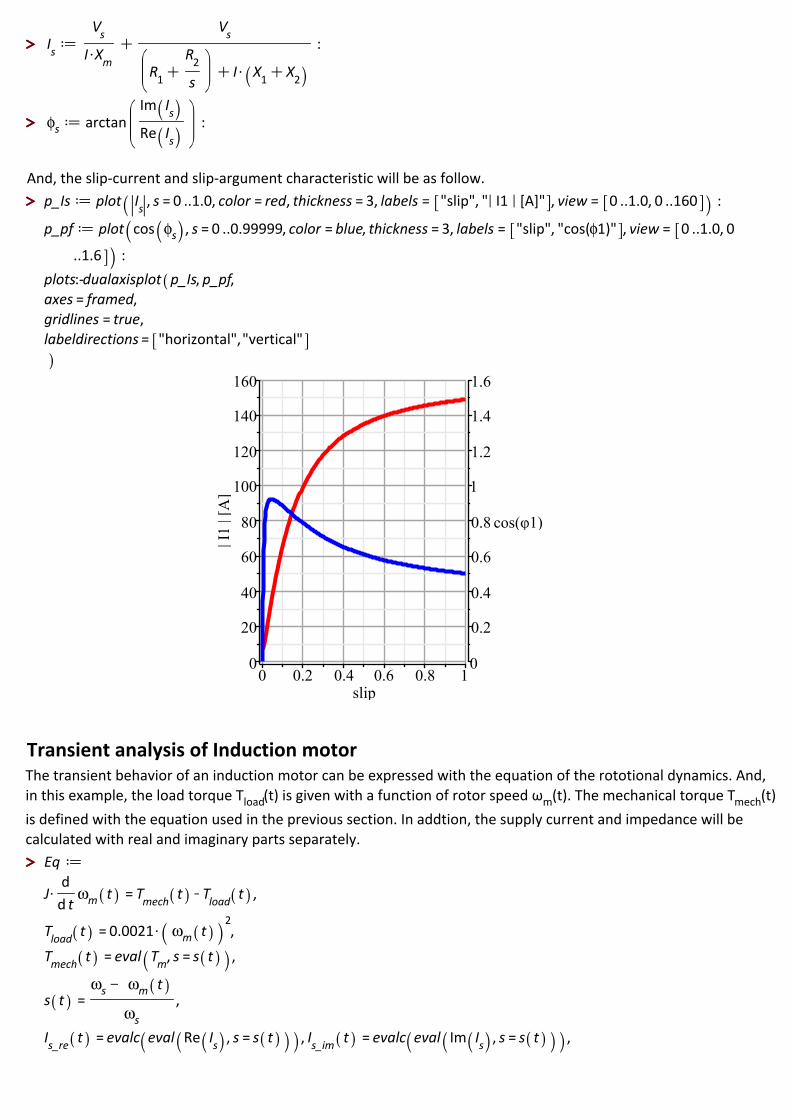
Also, the stator current and its argument are defined with the following equation.
> >
> >
> >
> >
> > And, the slip-current and slip-argument characteristic will be as follow.
Transient analysis of Induction motorThe transient behavior of an induction motor can be expressed with the equation of the rototional dynamics. And, in this example, the load torque Tload m(t). The mechanical torque Tmech(t)is defined with the equation used in the previous section. In addtion, the supply current and impedance will be calculated with real and imaginary parts separately.

> >
> >
> >
> >
> >
Solve the differential equation numerically
So, the transient behavior is given in this plot.

(3.2.1)(3.2.1)
> > > >
(3.2.2)(3.2.2)
> >
> >
> >
> >
> >
> >
> >
(3.2.3)(3.2.3)
And, the steady state of the motor also can be obtained as follow.
Stator current (absolute value) [A]
19.7250404892269Rotor speed [rpm]
1758.16096634761slip [-]
0.0232439074571207
Protection Settings with Overcurrent Relay and Impedance relayThis section describes a protection scheme
Overcurrent RelayBecause the motor inrush current will be higher than the pick-up current of the relay, the relay will begin to close itscontact. But, if the stator current I1 is lower than the pick-up current Ip before the area which is calculated with the following equation will exceed the setting K, the overcurrent relay will not trip. And, the behavior of the relay can be analyzed if the relay parameters are given.
The constant of the relay characteristic K [s], n, and the pick-up current Ip [A] is given as follows.
By using above parameters, the trip-time curve can be obtained with the following equation as the function of the

> >
> >
> >
> >
> >
> >
(4.1.1)(4.1.1)
current Is.
In the following plot, the trip-time curve, abs value of stator current and the pick-up current are shown.
As shown in the plot, the stator current will be much greater than the pick-up current at the beginning, but will become lower than it after the certain time. And, if the area, which is between the abs value of stator current and the pick-up current when stator current is bigger, is greater than the constant K, the relay will be operated to trip. So, the constant K need to be selected as the appropriate value.
In order to calculate the area, define the following procedure.
AreaIntegral := proc(dsol, Ip, n, startT, endT, numpoints)AreaIntegral := proc(dsol, Ip, n, startT, endT, numpoints)
Thus, the following value of Area [s] can be obtained. And, in this case, because the area is greater than the constant K [s], the trip will be happened.
5.78401628771791

> >
> >
> >
> >
> >
> >
> >
> >
Impedance RelayAt the beginning of the motor start-up, the motor impedance will be located inside the relay characteristic. And then, if it's under the locked-rotor condition, it will stay within the characteristic. On the other hand, under the normal condition, the impedance moves to outside the characteristic by following the trajectory of the motor impedance. The time that the motor impedance trajectory remains inside the relay characteristic can be computed with the following calculation. This also helps to determine the appropriate time delay for the relay.
So, the relay characteristic on R-X plain is defined with
Thus, in order to check the relay characteristic and motor impedance, the plot is shown as below.
As explained above, the motor impedance start from inside the relay characteristic, and then move to outside of it with the trajectory of the impedance.
In order to calculate the time to move out from the relay characteristic, the following procedure is defined.

> >
> >
> >
(4.2.1)(4.2.1)
> >
TimeDelay := proc(dsol, Zr0, startT, endT, numpoints)TimeDelay := proc(dsol, Zr0, startT, endT, numpoints)
Hence the time delay setting of the relay is obtained.
0.9262131067