SWITCHGEAR AND PROTECTION, STARTING OF 3 PHASE INDUCTION MOTOR
57
A PROJECT REPORT ON SWITCHGEAR AND PROTECTION BACHELOR OF TECHNOLOGY (Electrical Engineering) Submitted by: MD SAFDAR ALI Department of EE, JMI, NEW DELHI
-
Upload
safdar-ali -
Category
Engineering
-
view
1.257 -
download
3
Transcript of SWITCHGEAR AND PROTECTION, STARTING OF 3 PHASE INDUCTION MOTOR

APROJECT REPORT
ON
SWITCHGEAR AND PROTECTION
BACHELOR OF TECHNOLOGY(Electrical Engineering)
Submitted by:MD SAFDAR ALI
Department of EE, JMI, NEW DELHI
FACULTY OF ENGINEERING & TECHNOLOLGYJAMIA MILLIA ISLAMIA, NEW DELHI

CANDIDATE’S DECLARATION
I “MD SAFDAR ALI”12EES-23, a student of B.Tech (EE) hereby declared that I own the full responsibility for the information, result etc. provided in this project report titled “SWITCHGEAR AND PROTECTIN”. I have taken care of all respect to honor the intellectual property right and have acknowledged the contributions of other for using them in this academic purpose. I further declared that in case of any violation of intellectual property right or copyright I as the candidate would be fully responsible for the same. My supervisor and institute should not be held for full or partial violation of copyright if found at any stage of my degree.
Name of the student: MD SAFDAR ALI
Branch: ELECTRICALUnder the Guidance of
Mr. V. K PANDEY(SR. Deputy General Manager)
Mr. DIGVIJAY NATH TRIPATHI
(Assistant Manager)
L & T Engineering
PREFACE
Electricity and Electric Circuits forms the neural system of any industry analogous to
the nervous system of human. Electrical engineering is the foremost important part of
any manufacturing unit. Thus, to utilize the available Electrical energy efficiently &
judiciously various generations, control & distribution mechanisms are used. This
project provides a general overview of the system approach of design for safe and
efficient operation for entire life of electrical system.
Some of the few aspects of the fundamental system of Electric Engineering are
earthing and lightning protection, load list analysis, cable sizing, lighting.

ACKNOWLEDGEMENT
I would like to extend my heartfelt gratitude towards Larsen & Toubro Limited for
providing me with an excellent opportunity to undergo my internship from this
prestigious engineering company of our country.
On the personal front I must thank Mr. V. K PANDEY (Sr. Deputy General
Manager) for providing me the very first introduction on the practical side of the
subject, thereby opening an interesting training opportunity besides extending me
valuable guidance from time to time.
It is difficult to overstate my gratitude towards my training in-charge and mentor,
Mr. DIGVIJAY NATH TRIPATHI (Assistant Manager Electrical). It was only
with his active support, inspiration and efforts to explain concepts clearly, that this
training program is becoming very interesting and fruitful for me. Throughout my
training period he is a co36nstant source of encouragement, guidance, and
knowledge. Despite his busy work schedule with the ongoing projects, he took out
time to help me collect plenty of study material from the in-house resources as well
as made himself available to clear all the doubts and problems which arose during the
course of the training. It would have been nearly impossible to arrange the right input
to prepare this report without his generous help. And finally, I would like thank all
my fellow trainees for their help throughout my training period at L&T. I would like
to thank Miss. NIDHI MITTAL (HR) for providing me this opportunity to complete
my training.

OVERVIEW
L&T is India’s largest engineering and construction conglomerate (net worth
approx.14.5 billion US$ and workforce of 50000 employees) with additional interests
in electrical, electronics and IT. Today it is one of India’s biggest and best known
industrial organizations with a reputation for technological excellence, high quality of
products and services, and strong customer orientation. Seven decades of a strong,
customer-focused approach and the continuous quest for world-class quality have
enabled it to attain and sustain leadership in all its major lines of business.
L&T enjoys a premier brand image in India and its international presence is on the
rise, with a global spread of over 30 offices and joint ventures with world leaders. It
continues to grow its overseas manufacturing footprint, with facilities in China and
the Gulf region. The company's businesses are supported by a wide marketing and
distribution network, and have established a reputation for strong customer support.

PROJECT FLOW
To supplement the power generation needs of the state, the Government of Punjab
(GoP) had planned to develop 1200 ( +/- 10%) MW thermal power plant at village
Nalash near Rajpura, District Patiala, Punjab on Build, Own and Operate (BOO)
basis for 25 years. Accordingly, Nabha Power Limited ( NPL) , a wholly owned
company of Punjab State Electricity Board was established as Special Purpose
Vehicle (SPV) to develop the proposed Project . ARfQ / RfP was floated by PSEB in
line with Case 2 Competitive Bidding Guidelines of Govt. of India & L&T Power
Development Limited was identified as lowest bidder. The unit configuration was
adopted as 2 x 700 MW as per provisions in PPA .Rajpura is located at a distance of
about 7 km. from Rajpura Railway station and about 28 Km from Chandigarh
Airport. The Site is located 5 km form NH-1 & 7 km from NH-64.
NPL has placed order on L&T for design, engineering, manufacture, assembly, testing at manufacturer’s works, packaging and shipping, transport, delivery to site, receipt, unloading, handling and storage at site, Civil, Structural & Architectural Works, Erection, testing and commissioning and putting into operation of 2 X 700 MW Power Plant on EPC basis.

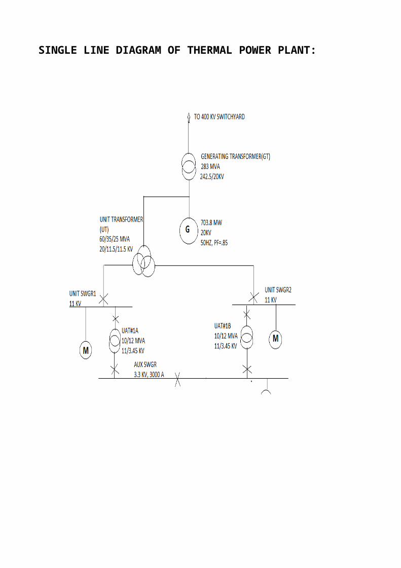
SINGLE LINE DIAGRAM OF THERMAL POWER PLANT:

DETAILS OF EQUIPMENTS IN RAJPURA THERMAL POWER PALNT:
Generator ratings
703.8 MW
20 KV
3 PH
50 HZ
0.85PF
Transformer ratings
60/35/25 MVA
20/110.5/11.5 KV
ONAN/ONAF/OFFAF
Dyn1yn1
Z= 12/12/24%
ON LOAD TAP CHANGER 10% IN STEPS OF 1.25% IN HV SIDE
Switchgear ratings
HT Switchgear
11 KV
2000 A
3 W
3 PH
40 KA FOR 1 SEC.

MV Switchgear
6.6/3.3 kv
3000 A
3 W
3 PH
50 KA FOR 1 SEC.
LT Switchgear
415 V
4000 A
3 W
3PH
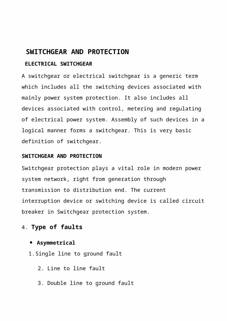
SWITCHGEAR AND PROTECTION ELECTRICAL SWITCHGEAR
A switchgear or electrical switchgear is a generic term which includes all the
switching devices associated with mainly power system protection. It also includes
all devices associated with control, metering and regulating of electrical power
system. Assembly of such devices in a logical manner forms a switchgear. This is
very basic definition of switchgear.
SWITCHGEAR AND PROTECTION
Switchgear protection plays a vital role in modern power system network, right from
generation through transmission to distribution end. The current interruption device
or switching device is called circuit breaker in Switchgear protection system.
4. Type of faults
Asymmetrical
1. Single line to ground fault
2. Line to line fault
3. Double line to ground fault
Symmetrical
1. LLL Fault
2. LLLG Fault

Fig: Asymmetrical faults
Fig: Symmetrical faults
SYMMETRICAL FAULT:
Symmetrical faults are those type of faults in which all the three phases gets involved
simultaneously. For example: triple line fault (L-L-L), triple line to ground fault (L-
L-L-G).

These are very severe faults and occur infrequently in the power systems. These are
also called as balanced faults and are of two types namely line to line to line to
ground (L-L-L-G) and line to line to line (L-L-L)
Only 2-5 percent of system faults are symmetrical faults. If these faults occur, system
remains balanced but results in severe damage to the electrical power system
equipments.
Above figure shows two types of three phase symmetrical faults. Analysis of these
fault is easy and usually carried by per phase basis. Three phase fault analysis or
information is required for selecting set-phase relays, rupturing capacity of the circuit
breakers and rating of the protective switchgear.
ASYMMETRICAL FAULT: In this type of faults, the fault occur mainly in one or two phases and are categorizes
as unbalanced fault. For example: single line to ground (L-G), double line to ground
(L-L-G).
Line to ground fault (L-G) is most common fault and 65-70 percent of faults are of
this type.
It causes the conductor to make contact with earth or ground. 15 to 20 percent of
faults are double line to ground and causes the two conductors to make contact with
ground. Line to line faults occur when two conductors make contact with each other
mainly while swinging of lines due to winds and 5- 10 percent of the faults are of this
type.

These are also called unbalanced faults since their occurrence causes unbalance in the
system. Unbalance of the system means that that impedance values are different in
each phase causing unbalance current to flow in the phases. These are more difficult
to analyze and are carried by per phase basis similar to three phase balanced faults.
ARC IN CIRCUIT BREAKER
During opening of current carrying contacts in a circuit breaker the medium in
between opening contacts become highly ionized through which the interrupting
current gets low resistive path and continues to flow through this path even the
contacts are physically separated. During the flowing of current from one contact to
other the path becomes so heated that it glows. This is called arc.
ELECTRICAL CIRCUIT BREAKER
Electrical Circuit Breaker is a switching device which can be operated manually as
well as automatically for controlling and protection of electrical power system
respectively. As the modern power system deals with huge currents, the spacial
attention should be given during designing of circuit breaker to safe interruption of
arc produced during the operation of circuit breaker. This was the basic definition of
circuit breaker.
TYPES OF CIRCUIT BREAKER
1) Oil Circuit Breaker
2) Air Circuit Breaker
3) SF6 Circuit Breaker
4) Vacuum Circuit Breaker
SWITCHGEAR EQUIPMENT FUNCTION
1. Fuse: To Protect circuit against over current and short circuit currents.
2.Circuit breaker
To make or break the circuit manually or remotely under normal condition and automatically under fault condition.
3.Isolator
To disconnect the part of the system for maintenance from live circuit under no current condition.
4.Earthing Switch
To discharge the voltage on the line ( due to charges of line capacitance to earth) after disconnecting line from live section.
5. Light using arrester
To divert high voltage surge towards the earth, due to lighting stroke or switching surges.
6. Current transformer
To stepping down the magnitude of current for measurement, protection and control. 7. Potential transformer
To stepping down the magnitude of line voltage for measurement, protection and control.
8. Relay
To disconnect the abnormally operating part so as to prevent the subsequent faults eg. Overload protection of a machine protects the machine and prevent insulation failure.

SWITCHGEAR DEVICES:
FUSE:
Fuse Link & Fuse Base,
High break range of low voltage fuse links have been designed to meet the requirements set for modern industrial installations & electrical power plants. Their breaking capacity is sufficient even for the highest short circuit levels, which are normally reached in practice.
The breaking capacity of the fuse links is 80KA at 415AC. The fuse links are suitable for use in both AC/ DC applications for over current and short circuit protection and have very low let through energy resulting in reduced electromagnetic stress and reliable short circuit clearance.
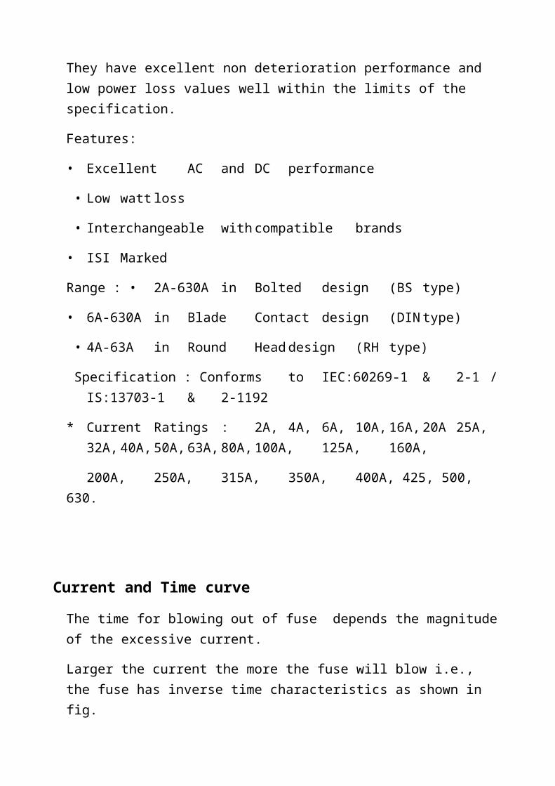
They have excellent non deterioration performance and low power loss values well within the limits of the specification.
Features:
• Excellent AC and DC performance
• Low watt loss
• Interchangeable with compatible brands
• ISI Marked
Range : • 2A-630A in Bolted design (BS type)
• 6A-630A in Blade Contact design (DIN type)
• 4A-63A in Round Head design (RH type)
Specification : Conforms to IEC:60269-1 & 2-1 /IS:13703-1 & 2-1192
* Current Ratings : 2A, 4A, 6A, 10A, 16A, 20A 25A,32A, 40A, 50A, 63A, 80A, 100A,125A,160A,
200A,250A,315A,350A,400A, 425, 500, 630.

Current and Time curve
The time for blowing out of fuse depends the magnitude of the excessive current.
Larger the current the more the fuse will blow i.e., the fuse has inverse time characteristics as shown in fig.
Advantages: 1. It is the cheapest form of protection available.2. It needs no maintenance.3. Its operation is inherently completely automatic unlike circuit breaker. 4. The minimum time of operation can be made much smaller than that with the
circuit breakers.5. It has inverse time-current characteristic.
Disadvantages:1. Considerable time is lost in rewiring or replacing a fuse after operation.2. On heavy short circuit discrimination between fuses in series cannot be obtained
unless there is considerable differences in the relative sizes of fuses concerned.3. The current-time characteristics of a fuse cannot always be correlated with of the
protected device.

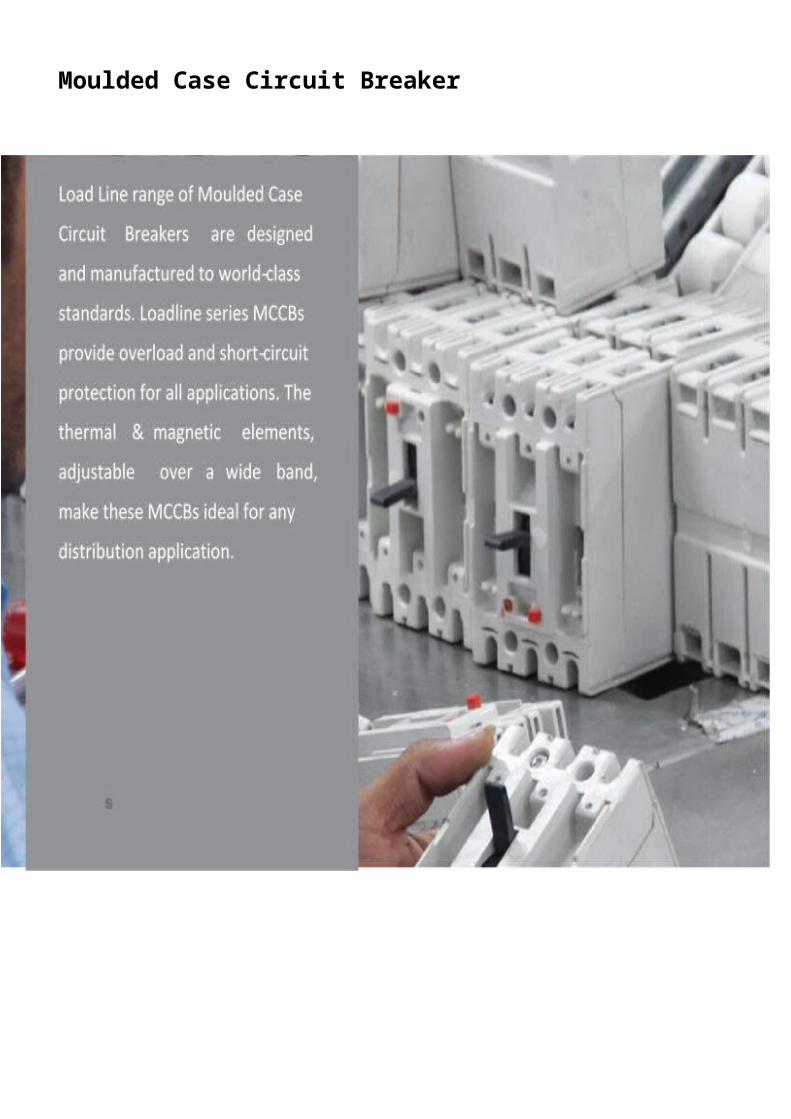
Electrical Distribution needs
are continuouslyevolvingin
residential, commercial and
industrial sectors. Improved
operational safety, continuity of
service, greater convenience
and operating cost have
assumed a tremendous
significance. Miniature Circuit
Breakers have been designed
to continuously adapt to these
changing needs.
Miniature Circuit Breaker

RangeA to 40A - ‘B’ Curve6
A to 63A - ‘C’ Curve0.5
0.5A to 63A - ‘D’ CurveA to 63A for DC Application0.5
ExecutionSingle Pole (1P)Single Pole & Neutral (1P+N)
Double Pole (2P) Three Pole (3P) Three Pole & Neutral (3P+N) Four Pole (4P)
SpecificationIS / IEC 60898 - 1
Accessories Auxiliary Switch Shunt Trip
TECHNICAL INFORMATION
Standard Conformity IS / IEC 60898 - 1
Type / Series B C DRated Current (In) A 6-40 0.5 - 63* 0.5 - 63*Rated Voltage (Ue) V~ 240/415 240/415 240/415Rated Frequency (f) Hz 50No. of Poles (Execution) 1 P, 1P+N, 2P, 3P, 3P+N, 4PRated Short Circuit BreakingCapacity
kA 10 10 0.5 - 32A - 10 kA40 A - 63A - 4.5kA
Magnetic Release Setting (3-5)In (5-10)In (10-20) InRated Insulation Voltage (Ui) V 660Rated Impulse Voltage (Uimp) kV 4Electrical / MechanicalEndurance (no. of operations)<32A
>32A
Ambient Working Temperature (oC)
20000
10000
-5 °C to 55°CTerminal Capacity (max) sq.mm 25Vibration g 3Shock 40 mm free fallProtection Class IP-20Installation Position Vertical / Horizontal

Mult iples of Rated Current (x In)
Tim
e (s
ec.)
10000.00
1000.00
100.00
10.00
1.00
0.10
0.01 1 2 3 5 10 20 30 100
1.13 1.45
B Curve C Curve D Curve
TRIPPING CHARACTERISTICS
Based on the Tripping Characteristics, MCBs are available in ‘B’, ‘C’ and ‘D’ curve to suit different types of applications.
‘B’ Curve: for protection of electrical circuits with equipment that does not cause surge current (lighting and distribution circuits). Short circuit release is set to (3-5) In
‘C’ Curve: for protection of electrical circuits with equipment that causes surge current (inductive loads and motor circuits).
Short circuit release is set to (5 - 10) In
‘D’ Curve: for protection of electrical circuits which causes high inrush current, typically 12-15 times the thermal rated current (transformers, X-ray machines etc.) Short circuit release is set to (10 - 20) In.
Moulded Case Circuit Breaker

FEATURES RANGE AND SPECIFICATION.
Features 1. Wide range: 16A to 1600A (AC).2. Compact dimensions.3. Adjustable thermal setting(70-100%).4. Adjustable magnetic setting.5. Suitable for use as switch disconnector.6. Push to trip button provision.7. Suitable for DC application up to 1600A.8. Separate main and arcing contacts.9. Wide range of accessories.
Range:
16A to 1600A in five frame sizes in single pole three pole and four pole with switched neutral execution.
Specification:
Conforms to IEC ; 60947-1&2/ IS 13947-1&2.
Applications:
1. Distribution feeders.2. Transformers.3. DG sets.4. APFC system.5. DC loads.6. UPS.7. Motors.8. Furnaces.

ACBBefore discussing about ACB schemes, let us first understand what an Air Circuit Breaker (ACB) is? As its name suggests, it is a device used to break or disconnect the circuit with air as an arc quenching medium in normal operating as well as fault conditions such as short circuit. It is designed to break the circuit under severe fault conditions where the current increases to a very high value capable of damaging the whole system.
Generally, fault sensing devices like relays which are an integral part of the ACB scheme sense the fault conditions and give a trip command to the ACB. The ACB then trips & isolates the faulty circuit from the healthy part. After the fault has been cleared or repaired the user can again switch on the ACB. Although these operations & protections can also be performed by other devices like MCCB’s or contactor coupled with relays. But the problem occurs when the current rises to such a high value that the arc’s produced at high current levels become so acute that it calls for equipment having higher breaking & withstanding capacity. These are incorporated in the ACB in such a way that it can handle as well as break such high amount of current. Thus the main difference between an ACB and other devices is the capability to quench heavy arcs. ACB has the following major parts:
1A Closing coil, which is responsible for closing the power contacts once the closing impulse is given to it.
2A Tripping coil, which is responsible for opening the power contacts when the tripping command is given or under faulty conditions.
3A Spring charging motor which charges a spring responsible for opening & closing the contacts.

ACB SCHEMES
Like any other scheme, the ACB scheme can also be broadly divided into power circuit and control circuit. The control circuit consists of interlocks to take care of the tripping and closing operations of the ACB.An ACB scheme can be divided into the following parts:
1. Power circuit or Main circuit2. Spring charging motor circuit3. Closing coil circuit4. Anti pumping circuit5. Tripping circuit6. Trip circuit supervision circuit
Spring Charging Motor CircuitIn an ACB, the closing operation is done using a high tension spring,
which can either be manually charged or automatically charged with the help of a motor. The energy stored in this spring, forces the power contacts to close. In motor charged ACB, the motor used to charge the spring needs to be disconnected after the spring is completely charged. To achieve this operation limit switches are provided. In case of an AC control supply one limit switch is provided whereas in case of DC control supply two limit switches are provided, one in +ve& one in –ve. This is because it is observed that in case of midpoint earthed DC system leakage current flows to earth from –ve and weakens the insulation. In order to avoid this the disconnection of +ve as well as –ve supply to stop the motor is a must. In an ACB scheme if electrical indication is required for spring charging, additional aux contactor is required. In case of DC control supply, aux contactor is connected between terminal F & H. In case of AC control supply aux contactor is connected between F & D. Circuit shown above is for DC spring charge motor. When spring is in discharged condition, limit switches on both the sides of motor will be in closed condition. So motor gets the supply & in turn starts charging the spring. Also aux contactor connected between F & H will pick up. NC contact of this contactor is used to give spring charged indication. Since contactor is in picked up condition, NC contact will open out & SPRING CHARGED I/L will not glow. When the spring gets fully charged, Limit switches opens out cutting the supply to the MOTOR. Along with this the contactor also drops off.

CLOSING COIL CIRCUIT
The closing coil circuit as shown in the figure consists of an electromagnetic coil and a series of NO & NC contacts responsible for various functions. The first NO gets closed only if the trip ckt. is healthy. The next NC contact of the lockout relay is put in series with the closing coil to ensure that the there is no fault. The NC contact of the auxiliary contactor is kept in series with the closing coil, which blocks closing command to closing coil till spring is charged. The NC contact of the anti-pumping relay ensures that ANTIPUMPING relay is not operated.
WHAT IS ANTI PUMPING?
Suppose if there is a continuous closing command to the closing coil circuit. Breaker closes. Now suppose a tripping command is given to the breaker the breaker will trip. But due to presence of a continuous close command, breaker will close again. It will again trip due to the presence of trip command & again close because of continuous close command. This continuous ON & OFF of a breaker is known as pumping. This operation can damage the ACB as well as the system life. In order to prevent this operation, circuit used is called as anti-pumping. Anti pumping circuit is as shown below. Now, when a closing command is given to the closing coil of the circuit, the breaker gets supply through a NC contact of the anti-pumping contactor. The closing coil is energized and the Breaker closes. Now an NO contact of the ACB is connected in series with the coil of Anti-pumping contactor closes. Thus when the breaker closes the contactor coil gets energized and it picks up. As a result the NO contact of the contactor connected across the
ACB NO contact also closes which provides an hold on to the contactor. Thus even if the breaker is tripped the contactor continues to be energized because continuous closing command is available. Hence the NC contact of the ANTI PUMPING contactor provided in series with the closing remains open & does not allow the continuous closing command to again close the breaker. Thus preventing any anti-pumping action.

TRIPPING CIRCUIT
The tripping circuit of an outgoing ACB is as shown below. It consists of a
tripping coil which trips the breaker whenever it is energized. It consists of a
TNC switch for manual tripping. When this switch is kept in the tripping
position, supply goes to trip coil & trip coil eneregises & trips the breaker. NO
contact of the lockout relay is also provided which trips the breaker when relay
senses the fault. The remote signals are also connected in series which can also
trip the breaker. An under voltage trip contact is provided in series through a
service position switch which energises the trip coil whenever an under voltage
is sensed by the main relay. The contact provided just beside the coil is an NO
contact of the circuit breaker which prevents the excitation of the tripping coil
when the breaker is open.
WHY IS A SERVICE POSITION SWITCH PROVIDED IN
SERIES WITH THE TRIP COIL?
Suppose an engineer is testing or servicing the breaker with the auxiliary
supply present. The breaker is kept in the test position. So the control signals are
all present. The HT breaker at this time is also OFF. The main relay will thus
sense it as an under voltage as there is no power supply available & give the trip
command to the breaker. It will thus lead to an accident. Similarly, if a remote
trip command is given from the control center by someone who is unaware of
the servicing will also lead to an accident. In order to prevent such an accident a
service position switch is provided so that the engineer can disconnect the
remote commands by keeping it on the test position while working on the
breaker.

TRIP CIRCUIT SUPERVISION CIRCUIT
Since the safety of a plant is largely dependent on the speed of isolation of the
faulty section, it is very important to continuously monitor the trip circuit of the
breaker feeders. A simple circuit using a trip circuit supervision relay is as
shown in the tripping circuit. The relay provided in the circuit checks and
verifies the continuity of the coils & all the connected loops. It opens whenever
the trip circuit is faulty. NO of this relay is provided in series with the closing
coil of the breaker, which prevents the closing of the breaker whenever the trip
circuit is unhealthy.

STARTING METHODS IN INDUCTION MOTORS
1. Direct On Line
2. Star/Delta method
3. Auto Transformer
4. Soft starter
5. VFD starter
DIRECT ON LINE (DOL) MOTOR STARTER
Different starting methods are employed for starting induction motors because
Induction Motor draws more starting current during starting. To prevent damage
to the windings due to the high starting current flow, we employ different types
of starters.
The simplest form of motor starter for the induction motor is the Direct On Line
starter. The Direct On Line Motor Starter (DOL) consist a MCCB or Circuit
Breaker, Contactor and an overload relay for protection. Electromagnetic
contactor which can be opened by the thermal overload relay under fault
conditions.
Typically, the contactor will be controlled by separate start and stop buttons,
and an auxiliary contact on the contactor is used, across the start button, as a
hold in contact. I.e. the contactor is electrically latched closed while the motor is
operating.
PRINCIPLE OF DIRECT ON LINE STARTER (DOL)To start, the contactor is closed, applying full line voltage to the motor windings. The motor will draw a very high inrush current for a very short time, the magnetic field in the iron, and then the current will be limited to the Locked Rotor Current of the motor. The motor will develop Locked Rotor Torque and begin to accelerate towards full speed.As the motor accelerates, the current will begin to drop, but will not drop significantly until the motor is at a high speed, typically about 85% of synchronous speed. The actual starting current curve is a function of the motor design, and the terminal voltage, and is totally independent of the motor load.The motor load will affect the time taken for the motor to accelerate to full speed and therefore the duration of the high starting current, but not the magnitude of the starting current.Provided the torque developed by the motor exceeds the load torque at all speeds during the start cycle, the motor will reach full speed. If the torque delivered by the motor is less than the torque of the load at any speed during the start cycle, the motor will stops accelerating. If the starting torque with a DOL starter is insufficient for the load, the motor must be replaced with a motor which can develop a higher starting torque.
The acceleration torque is the torque developed by the motor minus the load torque, and will change as the motor accelerates due to the motor speed torque curve and the load speed torque curve. The start time is dependent on the acceleration torque and the load inertia.DOL starting have a maximum start current and maximum start torque.This may cause an electrical problem with the supply, or it may cause a mechanical problem with the driven load. So this will be inconvenient for the users of the supply line, always experience a voltage drop when starting
a motor. But if this motor is not a high power one it does not affect much.

FIG: DOL STARTER
STAR DELTA STARTERThis is a starting method that reduces the starting current and starting torque.
Star delta starter design normally consists of three contactors, an overload relay
and a timer for setting the time in the star-position (starting position).
For the star delta starter, a motor must be in delta connected during a normal run
and the main purpose is to be able to use star delta starter.Star delta starter
received the starting current is about 30 % of the starting current during direct
on line start and the starting torque is reduced to about 25 % of the torque
available at a D.O.L start.

Star delta starter only works when the application is light loaded during the start. If the motor is too heavily loaded, there will not be enough torque to accelerate the motor up to speed before switching over to the delta position.
DESCRIPTION OF STAR DELTA STARTER OPERATION:
For star delta starter, the basic function is to enable the motor to start and the motor windings are configured in a star formation to the supply voltage.
The voltage applied for star delta starter to the individual motor winding is therefore reduced by a factor of 1/√3 = 0.58 this connection amounts to approximately 30% of the delta values. The starting current is reduced to one third of the direct starting current.
Due to the reduced starting torque, the star-delta-connection is suitable for drives with a high inertia mass but a resistance torque which is low or only increases with increased speed. It is preferably used for applications where the drive is only put under a load after run-up.
After motor run-up, in most cases an automatic timing relay controls the switch-over from star to delta. The run-up using star connection should last until the motor has reached the approximate operational speed so that after switching to delta, as little post acceleration as possible is required. Post-acceleration in delta connection will instigate high currents as seen with direct on-line starting. The duration of start in star connection depends on the motor load. During delta connection, the full mains voltage is applied to the motor windings. To enable a switch-over from star to delta, the six ends of the motor winding are connected onto terminals. The contactors of a star-delta starter switch over the windings accordingly.

HOW STAR DELTA STARTER WORKS?
Starting in star, the main contactor connects the mains to winding endings U1, V1, W1.The star contactor shorts winding endings U2, V2, W2.
After successful run-up, the star contactor switches itself off and the delta contactor connects terminals U1/V2, V1/W2, W1/U2.
When changing from star to delta, we should pay attention to ensure it running in the correct phase sequence. Incorrect phase sequence can lead to very high current peaks during the cold switch-over pause, due to the easy torque reduction following re-start.
High peaks current can damage the motor windings and stress the control gear unnecessarily. The rotation of the motor has to be considered as well. If wrong rotation, we should change the rotation by switch the phase. I discuss detail about How to change star delta starter motor rotation in my separate post.
For star delta starter circuit diagram, wiring technique and motor base
termination, Please read my post for star delta motor connection. Also for
simple star delta control circuit wiring and types of star delta starter, please refer
to my post for Electro mechanical star delta.

Fig: STAR DELTA STARTER
AUTOTRANSFORMER-STARTING
An autotransformer starter enables the start of squirrel-cage motors using a
reduced starting current, since the voltage is reduced during start. Contrary to a
star-delta connection, only three wires to the motor and 3 motor connections are
required. This connection is particularly widely used in English-speaking
countries.
During start-up, the motor is connected to the autotransformer’s tappings. This
means that the motor starts up with a reduced voltage and a correspondingly
low current. The autotransformer reduces the current in the mains supply line

further and in accordance with its ratio. Like the star delta connection, the
autotransformer starter has a favourable torque-current take-up ratio.
In order to adapt the motor start characteristics to the torque requirement,
autotransformers are usually equipped with three selectable tappings (e.g. 80%,
65%, 50%). When the motor has almost reached its rated torque, the star
connection on the transformer is opened. The transformer’s partial windings act
as chokes in series to the motor windings, and therefore, like the uninterrupted
star delta connection, the motor speed does not drop during switch over. After
the main contactor has been switched in, the motor windings are applied to the
full mains voltage. Finally, the transformer is disconnected from the mains.
Depending on tapping and the motor’s starting current ratio, the starting current
amounts to 1 - 5 x Ie. The available torque is reduced in ratio to the starting
current.
FIG: AUTO TRANSFORMER STARTER

CONCEPT OF DRAWOUT FEEDER:The starter circuitry is generally accommodated in draw out type of feeder in a
MCC panel. This type of feeder can be racked in or racked put with the help of
racking handle, racking screw & sliding telescopic rails. Power supply to the
feeder is given through the STABIN contact mounted on the dropper & power
supply to customer is given through the D/O O/G power contact. Control supply
from external side as well as interlock/feedeback from/to outside is given
through SICs (Secondary Isolating Contacts). There are three types of SICs (i.e.
SERVICE, TEST & SERVICE + TEST). SERVICE SICs can be mounted in
front as well as rear column. However TEST & SERVICE + TEST SICs are
mounted only in front column.
Fully draw-out module has 3 distint functional positions additonal 2 positions
for maintenance purpose.
1. SERVICE: The module has stab-in type of contacts and power contacts on its
rear side (behind the base plate). The stab-in contacts get connected to the
droppers and the power contacts get connected to the outgoing power terminals
in this position. In this position SERVICE SICs & SERVICE +TEST SICs
remain engaged. However TEST SICs remain disengaged.
2. TEST: After opening the door module is racked out to bring it to TEST
position. In this position, STAB-IN as well as O/G contact gets disengaged.
Hence no power supply is available to module. In this position SERVICE SICs
gets disengaged. However TEST &
SERVICE +TEST SICs remain engaged. In this position, Control circuit can be
tested selectively.
3. ISOLATED: In this position, both power and control SICs get disengaged.
4. MAINTENANCE: In this position, one can get access to all components.
5. HINGED OUT: In this position, one can get access to components on rear
and incoming contacts without removing the module.

CRITICAL THINGS TO BE TAKEN CARE WHILE MAKING A STARTER SCHEME:
Following things need special attention while making a scheme drawing for any
starter feeder:
1. CONTROL CABLING: The control cables for commands coming from
customer side (remote, DCS, PLC, etc.) are generally multi-core cables.
Therefore whenever control terminals are numbered for external commands,
attempt should be made to keep the numbers of these terminals serially. This
makes the cable termination at site easier.
2. DRAW-OUT / FIXED FEEDERS: The starter feeders can be offered in
draw-out as well as fixed type. While making scheme, the type of feeder should
be kept in mind. The type of draw-out and fixed feeder affects the type of
control terminals and power terminals. The representation of the two types of
terminals is different in a scheme diagram.
3. CONTROL SUPPLY: Control supply coming to the control circuit of the
feeder should be shown appropriately. It may be coming from inside the feeder
or from the switchboard or any external supply. The auxiliary bus, from which
the supply is tapped, should be named correctly in accordance with the general
arrangement drawing.
4. CONTROL CIRCUIT PROTECTION: The fuses or MCBs given for the
control circuit protection should be appropriately selected. The rating of the
fuses/MCBs is to be selected according to the equipments connected in the
circuit.
According to the application, the type of SIC is to be selected.
5. SIC ARRANGEMENT: The SICs have specific position in a draw-out
module. Therefore the arrangement of the SICs should be checked in a scheme.
The number of SICs that can be accommodated also should be checked with
respect to the feeder size. Also it should be kept in mind that Test SICs and
Service + Test SICs can only come in the front column of the module.

6. STAR-DELTA SCHEME LOGIC: If any interlocks are there in a star-delta
starter feeder, the scheme should be re-checked for logic. The operation of the
feeder in star and delta modes should be analysed.
ADVANTAGES OF SOFT STARTERS: • Increased acceleration time can be beneficial for motor and machine.
• The starting current is reduced or can be limited.
• The torque is adapted to the corresponding load.
• For pumps, surges during start and stop can be avoided.
• Jerky movements and shocks, which could hamper a process, are avoided.
• The wear and tear of belts, chains, gears and bearings is avoided.
• By means of the different controls, simplified automation is possible.

POSSIBLE APPLICATIONS:
• Travelling cranes, conveyor belts, drives
• Mixers, mills, crushers
• Pumps, compressors, ventilators
• Drives with gears, chains, belts, clutches
Pumps: By means of a special pump control it is possible to eliminate pressure
impact, which occurs during pump start and stop.
Compressors: For compressors, the speed can decrease during switch-over from
star to delta. A soft starter ensures a continuous start. A reduction in speed does
not occur.
Single-phase motors: If a single-phase motor is to be powered using a soft
starter, a single-phase full-wave controlled soft starter is required.
In general: The soft starter represents an economical substitute for star-delta
systems and offers superior performance. For applications with where a high
starting torque is required, a soft starter should be the preferred choice.
THANK YOU