Induction Heating Process
11
Induction Heating Process During the thixoforming process, it is very important to obtain a uniform temperature, which affects the uniformity of the solid fraction, throughout the billet. Consequently, a heating method that can provide a suitable temperature profile throughout the billet must be chosen. Other parameters that must be considered include heating time (in order to minimize the total processing time), the level of control, and temperature consistency. An optimal design of the induction coil has been identified that best meets these criteria. In a previous study, the theoretical optimal coil design was verified through the FEM simulation of the induction heating process by using a general purpose finite element analysis code, ANSYS. So, in this study, the suitability of the coil design was also demonstrated by conducting induction-heating experiments. The optimal reheating conditions to apply the thixoforming (thixoforging and semisolid die casting) process were investigated by varying the reheating time, the holding time, the reheating temperatures, the capacity of the induction heating system, and the size of the adiabatic material. The final holding time was observed to be the most important factor in obtaining a fine globular microstructure and to prevent coarsening in the three-step reheating process. I. INTRODUCTION FOR the thixoforming process, both the coexisting sol- idus-liquidus phase and the reheating conditions to obtain the globular microstructure are very important. In a study on the induction heating process of semisolid materials (SSM), Sebus and Henneberger [1] verified that the design of the induction coil had an important influence on the induction heating process. Matsuura and Kitamura [2] suggested that it is very important not to destroy the crystallization matrix of semisolid metals due to the change of the size of spherical dendrite grains during reheating. In a study on the induction heating of semisolid aluminum alloys, Midson et al. [3] pro- posed that a coil design was necessary for uniform induction heating. Rudnev and co- workers [4–7] showed that the required temperature distribution along the end of the slug depends on the frequency, the coil and slug geometry (includ- ing the slug- to-coil air gap and coil overhang), the material properties of the slug, its emissivity, coil refractory, power density, and cycle time. Hirt and co-workers [8,9] and Garat and co- workers [10–13] have both repeatedly emphasized that it is important to prevent the coarsening for thixoforming, because, generally, an average grain size below 100 m m in the reheated state will be sufficient to ensure a homogeneous material flow of the semisolid alloy and good dimensional stability during die filling. Kang et al. [14] experimentally proposed the optimal reheating conditions for thixoforging and the semisolid die casting processes using SSM (A356 alloys) with d 3 l 5 39 3 85 (mm) and d 3 l 5 76 3 60 (mm). Jung and Kang [15] proposed and manufactured an the billet and to obtain a globular microstructure for thixo- forging and semisolid die casting processes by using A356 (ALTHIX) alloy with d 3 l 5 76 3 90 (mm) and a 60 Hz frequency for the induction heating system. Moreover, they demonstrated the suitability of the coil design by performing reheating experiments. The effects of reheating time, billet size, and holding temperature on microstructures for the semisolid die casting and thixoforging of Al-6 Pct Si-3 Pct Cu-0.3 Pct Mg alloy (ALTHIX 86S) have not been reported. Therefore, the objec- tive of this study is to determine the effects of the reheating conditions on the globularization of microstructures. The reheating time, the holding temperature, the holding time, the adiabatic material size, and the capacity of the induction heating system were considered as parameters of the globu- larization of microstructure. Particular interest is focused on the solutions avoiding the coarsening phenomena. Moreover , as the first part of our investigation, the optimal coil design to reduce the temperature gradient of the ALTHIX 86S billet and to obtain the globular microstructure was theoretically proposed and manufactured. The suitability of the coil design was demonstrated by using reheating experiments. II. THE NECESSITY OF INDUCTION COIL DESIGN During induction heating, the relationship between time and temperature must be controlled exactly to obtain a uni- form temperature distribution over the entire cross-sectional area. Because the initial eutectic temperature (i.e., initial solid fraction) in the thixoforming process is the key parame- ter to filling results in the thixoforming process, an accurately controllable induction heating method must be selected as the reheating process. For the thixoforming process, the reheating of the billet in the semisolid state as quickly and homogeneously as possible is one of the most decisive aspects. From this point DaWei Induction Heating Machine Co.,Ltd www.gpgyjr.com.cn www.dw-inductionheating.com E-mail: [email protected] METALLURGICAL AND MATERIALS TRANSACTIONS A VOLUME 30A, NOVEMBER 1999—2967 DaWei Induction Heating Machine Co.,Ltd E-mail: [email protected]
Transcript of Induction Heating Process

Induction Heating Process
During the thixoforming process, it is very important to obtain a uniform temperature, which affects the uniformity ofthe solid fraction, throughout the billet. Consequently, a heating method that can provide a suitable temperature profilethroughout the billet must be chosen. Other parameters that must be considered include heating time (in order tominimize the total processing time), the level of control, and temperature consistency. An optimal design of theinduction coil has been identified that best meets these criteria. In a previous study, the theoretical optimal coil designwas verified through the FEM simulation of the induction heating process by using a general purpose finite elementanalysis code, ANSYS. So, in this study, the suitability of the coil design was also demonstrated by conductinginduction-heating experiments. The optimal reheating conditions to apply the thixoforming (thixoforging and semisolid diecasting) process were investigated by varying the reheating time, the holding time, the reheating temperatures, thecapacity of the induction heating system, and the size of the adiabatic material. The final holding time was observedto be the most important factor in obtaining a fine globular microstructure and to prevent coarsening in the three-stepreheating process.
I. INTRODUCTION
FOR the thixoforming process, both the coexisting sol-
idus-liquidus phase and the reheating conditions to obtain the globular microstructure are very important. In a study on the induction heating process of semisolid materials(SSM), Sebus and Henneberger[1] verified that the designof the induction coil had an important influence on theinduction heating process. Matsuura and Kitamura[2]
suggested that it is very important not to destroy thecrystallization matrix of semisolid metals due to the changeof the size of spherical dendrite grains during reheating. In astudy on the induction heating of semisolid aluminumalloys, Midson et al.[3] pro- posed that a coil design wasnecessary for uniform induction heating. Rudnev and co-workers[4–7] showed that the required temperaturedistribution along the end of the slug depends on thefrequency, the coil and slug geometry (includ- ing the slug-to-coil air gap and coil overhang), the material properties ofthe slug, its emissivity, coil refractory, power density, andcycle time. Hirt and co-workers[8,9] and Garat and co-workers[10–13] have both repeatedly emphasized that it isimportant to prevent the coarsening for thixoforming,
because, generally, an average grain size below 100 mm in
the reheated state will be sufficient to ensure a homogeneousmaterial flow of the semisolid alloy and good dimensionalstability during die filling. Kang et al.[14] experimentallyproposed the optimal reheating conditions for thixoforging and the semisolid die casting processes using SSM (A356alloys) with d 3 l 5 39 3 85 (mm) and d 3 l 5 76 3 60 (mm). Jung and Kang[15] proposed and manufactured an
the billet and to obtain a globular microstructure for thixo-forging and semisolid die casting processes by using A356 (ALTHIX) alloy with d 3 l 5 76 3 90 (mm) and a 60 Hzfrequency for the induction heating system. Moreover, they demonstrated the suitability of the coil design by performing reheating experiments.
The effects of reheating time, billet size, and holding temperature on microstructures for the semisolid die castingand thixoforging of Al-6 Pct Si-3 Pct Cu-0.3 Pct Mg alloy(ALTHIX 86S) have not been reported. Therefore, the objec-tive of this study is to determine the effects of the reheatingconditions on the globularization of microstructures. The reheating time, the holding temperature, the holding time,the adiabatic material size, and the capacity of the induction heating system were considered as parameters of the globu-larization of microstructure. Particular interest is focused on the solutions avoiding the coarsening phenomena. Moreover, as the first part of our investigation, the optimal coil designto reduce the temperature gradient of the ALTHIX 86S billet and to obtain the globular microstructure was theoreticallyproposed and manufactured. The suitability of the coil design was demonstrated by using reheating experiments.
II. THE NECESSITY OF INDUCTION COIL DESIGN
During induction heating, the relationship between time and temperature must be controlled exactly to obtain a uni- form temperature distribution over the entire cross-sectional area. Because the initial eutectic temperature (i.e., initial solid fraction) in the thixoforming process is the key parame- ter to filling results in the thixoforming process, an accurately controllable induction heating method must be selected as the reheating process.
For the thixoforming process, the reheating of the billet in the semisolid state as quickly and homogeneously as possible is one of the most decisive aspects. From this point
DaWei Induction Heating Machine Co.,Ltd www.gpgyjr.com.cn www.dw-inductionheating.com
E-mail: [email protected]
METALLURGICAL AND MATERIALS TRANSACTIONS A VOLUME 30A, NOVEMBER 1999—2967
DaWei Induction Heating Machine Co.,Ltd
E-mail: [email protected]

of view, the design of the induction coil is very important.For a real system consisting of coil and billet, the inducedheat over the length of the billet is normally not equallydistributed, and consequently, there is a nonuniform tempera-ture distribution. Therefore, an important point for the opti-mization of coil design is to verify the correct relationshipbetween coil length and billet length.
In this study, the optimal coil design of the commercialinduction heating system (for semisolid forming: 60 Hz) toobtain the globular microstructure for variations of SSMand specimen size (diameter and length) was theoreticallyproposed and manufactured. The suitability of the coil de-sign will be demonstrated by using induction heatingexperiments.
If ALTHIX 86S with d 3 1 5 76 3 70 (mm) is assumed to be 11 billets heating for a unit hour to 578 8C, the thermal capacity (Q) and the production rate (Pr) are calculated by Stansel’s[17] data (in the case of a temperature rise to 510 8C, the thermal capacity and the production rate are Q 5 145 kW h/t and Pr 5 0.01 t/h, respectively) and linear interpolation.
The minimum heated surface area (As) and the minimum heated length (lw) can be determined as follows:
P P 3 Q As 5
t 5
r [3]
Pa Pa
As lw 5
pd [4]
To determine the coil inner diameter Di and optimal coil length H, recommended air gaps (1/2 (Di 2 d )) for through-heating coils and property values to calculate the optimalcoil length are shown in Tables I and II, respectively.
By using linear interpolation with Table I, the coil innerdiameter Di is calculated, and from the result of Eq. [4], theoptimal coil length H is calculated as follows:
III. COIL DESIGN FOR INDUCTION HEATING
For uniform reheating in this study, the optimal coil length,H, and a coil inner diameter, Di , of the induction heatingsystem were designed, as shown in Figure 1.
To consider the main surface power loss in inductionheating, the idealized power density (Ps) must be representedas the actual power density (Pa), which is modified to allowfor the ratio (d/2dF) of a finite current depth of penetration(dF) of material and billet diameter (d ).
H 5 lw 1 (25 to 75) [5]
Therefore, from the preceding considerations, the coildimensions for the SSM (ALTHIX 86S alloys) with d 3 l 5 76 3 70 (mm) are proposed in Table III, and the experi-ments of induction heating are carried out using thedesigned dimensions.
We demonstrated the suitability of an optimal coil design through the finite element modeling simulation of the induc-tion heating process by using a general purpose finite ele-ment analysis code, ANSYS.*[20] In addition, the results of
2ra dF 5 ! [1]
mv
Ps (us 2 uc)idealized 6.89 (u 2 u ) K s c Pa 5 5 [2]
u 2 u d s c
uS 2 uC In Eq. [2], 5 k can be obtained from the
(uS 2 uC)idealized
variation curves of temperature in a cylinder with finite current depth of penetration.[16]
In the preceding equation, ra , m, v, k, and us2uc are the resistivity of ALTHIX 86S, the magnetic constant, theangular frequency, the thermal conductivity, and the maxi-mum surface-center temperature difference, respectively.
*ANSYS is a trademark of Swanson Analysis Systems, Inc., Houston, PA.
induction heating CAE based on the optimal coil design forvariations of SSM and specimen size coincided with thoseof the induction heating experiment.[20,21]
IV. INDUCTION HEATING EXPERIMENTS
For the thixoforming process, the billet must be reheated to a semisolid state. The induction heating process is very important in the forming process of an SSM billet, the pro- cess not only being necessary to achieve the required SSM billet state, but also to control the microstructure of the billet.
The SSM used in this study was an ALTHIX 86S alloy fabricated by electromagnetic stirring by PECHINEY in France. This SSM is a casting alloy used in the development of automotive parts. The chemical composition is shown in Table IV, and the microstructure of the raw material is shown in Figure 2.
The ALTHIX 86S alloy is machined to d 3 l 5 76 3 70
Table I. Recommended Air Gaps [1/2 (Di 2 d )] for Through-Heating Coils[16]
Billet Diameter (d, mm) Billet
Temperature (8C) Frequency 0 to 60 60 to 125 125 to 250
50/60 Hz 550 850
12 12
12 20
12 40
Fig. 1—Schematic illustration of induction heating of cylindrical specimen.
2968—VOLUME 30A, NOVEMBER 1999 METALLURGICAL AND MATERIALS TRANSACTIONS A

Table II. Property Values to Calculate the Optimal Coil Length (Specimen Size: d 3 l 5 76 3 70 mm, f 5 60 Hz,
and k 5 0.58)
Parameters Symbol Unit Values Reference
Maximum surface-center temperature difference Current depth of penetration Thermal conductivity Idealized power density Resistivity of ALTHIX 86S Magnetic constant Angular frequency Finite current depth of penetration Actual power density Thermal power Production rate Thermal capacity Minimum heated surface area Billet diameter Minimum heated length
us 2 uc
d
k
Ps
ra
m
v
dF
Pa
Pt
Pr
Q As
d lw
K mm W/m K kW/m2
mVm H/m rad/s
m kW/m2
kW dimensionless
kW m2
mm mm
4 10.7 109
22.91 0.0639
4p 3 1027
— 18 19 — 19 16 — — — — 17 — — — —
120p
1.64 3 1022
39.5 1.33
0.01 t/h 133.08 h/t
30.67 3 1023
76 141
(mm).[20,21] Thermocouple holes (2-mm diameter) to mea-sure the temperature are accurately machined at 45 mm fromthe surface of the billet and at 10 mm from the lateral of the billet. To accurately control the temperature of the SSM,K-type CA thermocouples (sheath type) of w 1.6 mm areinserted into the billet. Thermocouples are calibrated by means of being inserted into water of 100 8C. The accuracyof thermocouples is approximately 0.2 pct. Data logger TDS- 302 (Tokyo Sokki Kenkyuio Co., Ltd.) was used to receive the data, and the heating temperature was set to the datum at thermocouple position (b) in Figure 1.
To determine the optimal reheating conditions, the follow- ing parameters were used for the globularization of the microstructure and a small temperature gradient: the capacity
Table III. Designed Dimensions of Induction Heating
Device ( f 5 60 Hz, d 5 10.7 mm,[18] l 5 70 mm, and k
5 0.58)
Minimum Heating Length
(lw , mm)
Billet Diameter (d, mm)
Coil Inner Diameter (Di , mm)
Optimal Coil Length
(H, mm)
76 100 141 166 to 216
Table IV. Chemical Compositions of ALTHIX 86S
Si Fe Cu Mn Mg Cr Zn Ti Pb
of the induction heating system (Q), the reheating time (ta), Minimum (pct) Maximum (pct)
5.5 6.5
— 0.15
2.5 3.5
— 0.03
0.30 0.40
— —
— 0.05
— 0.20
— 0.03 the holding temperature (Th), the holding time (th), the reheat-
ing step, and the adiabatic material size. The reheating exper-iments were performed under the conditions in Table V. Themeanings of the symbols used in Table V are the same asthose shown in Figure 3.
V. THE RESULTS OF INDUCTION HEATING
AND DISCUSSION
After induction heating, the microstructure of the SSMmust be globular. Moreover, when the SSM is fed from the induction heating system to the die, the shape of the SSMmust be maintained. Therefore, the capacity of the induction heating system (Q), the reheating time (ta), the holding tem- perature (Th), the holding time (th), the reheating step, andthe adiabatic material size were considered as parametersof the experiment to observe the globularization of the micro-structure and a small temperature gradient.
The relationship between temperature and solid fraction of the ALTHIX 86S alloy is given in Figure 4. The temperaturescorresponding to the solid fractions of 50 and 55 pct are 582 8C and 578 8C, respectively.[10] Generally, these solid fractions of 50 and 55 pct are for semisolid die casting andthixoforging, respectively.
Fig. 2—Microstructure for raw material of ALTHIX 86S.
(mm). The experiments of induction heating were performedby using an induction heating system (frequency: 60 Hz)with the capacity of 50 kW. As shown in Figure 1, to achieveuniform heating, the heating coil of the induction heatingsystem is made by machining to D0 3 H 5 120 3 180
VI. SOLID FRACTION 55 PCT
Reheating experiments 1 through 19 were performed for
fs 5 55 pct. From experiments 1 through 10, the experiments
METALLURGICAL AND MATERIALS TRANSACTIONS A VOLUME 30A, NOVEMBER 1999—2969

Table V. Experimental Conditions for Reheating of Semisolid Aluminum Alloy (ALTHIX 86S), Test Specimen Size:
d 3 1 5 76 3 70 (mm)
Holding Temperature
Th (8C)
Adiabatic Material
Size (mm) D 3 W 3 L
Reheating Time
ta (min)
Holding Time
th (min) Total Time (min)
Capacity Q (kW) Number ta1 ta2 ta3 Th1 Th2 Th3 th1 th2 th3
1 2 3 4 5 6 7 8 9
10 11 12 13 14 15 16 17 18 19 20 21 22 23 24 25 26 27 28
4 4 4 4 4 4 4 4 4 4
10 12
8 8 4 4 4 4 4 4 4 4 4 4 4 4 4 4
3 3 3 3 3 3 3 3 3 3 — — 1 2 3 3 3 3 4 3 3 3 3 3 3 3 3 3
1 1 1 1 1 1 1 1 1 1 — — — — 1 1 1 2 2 1 1 1 1 1 1 1 1 1
350 350 350 350 350 350 350 350 350 350 578 578 567 567 350 350 350 350 350 350 350 350 350 350 350 350 350 350
567 567 567 567 567 567 567 567 567 567 — — 578 578 567 567 567 567 567 572 572 567 567 567 567 567 567 567
578 578 578 578 578 578 578 578 578 578 — — — — 578 578 578 578 578 582 582 582 582 582 582 582 582 582
1 1 1 1 1 1 1 1 1 1 2 2 3 1 1 1 1 1 1 1 1 1 1 1 1 1 1 1
3 3 3 3 3 3 3 3 3 3 — — 2 2 3 3 3 3 3 3 3 3 3 3 3 3 3 3
2 2 2 2 2 2 2 2 2 2 — — — — 1 2 3 2 2 2 2 2 2 2 2 2 4 3
14 14 14 14 14 14 14 14 14 — 12 14 14 15 13 14 15 15 16 14 14 14 14 14 14 14 16 15
8.398 7.480 5.945 3.912 4.096 4.941 5.292 5.544 5.482 5.012 5.544 5.544 5.544 5.544 5.544 5.544 5.544 5.544 5.544 5.544 5.231 4.941 4.806 5.376 5.448 5.128 5.128 5.128
without without without without without without without without without without
50 3 50 3 20 50 3 50 3 20 50 3 50 3 20 50 3 50 3 20 50 3 50 3 20 50 3 50 3 20 50 3 50 3 20 50 3 50 3 20 50 3 50 3 20 50 3 50 3 20 50 3 50 3 20 50 3 50 3 20 50 3 50 3 20 50 3 50 3 20 50 3 50 3 20 53 3 53 3 19 53 3 53 3 19 53 3 53 3 19
Fig. 3—Input data diagram of reheating conditions to obtain the globu- lar microstructure. Fig. 4—Relationships
ALTHIX 86S. between temperature and solid fraction for
were carried out at the reheating conditions of ta1 5 4 min, ta2 5 3 min, ta3 5 1 min, th1 5 1 min, th2 5 3 min, th3 5 Therefore, experiments 11 and 12 were performed at one- 2 min, Th1 5 350 8C, Th2 5 567 8C, and Th3 5 578 8C, with a changing capacity of induction heating system to determine the optimal capacity according to the heating time. In the case of the capacity (Q) of 5.544 kW, the billets reach the set temperature with a small temperature difference.
step heating conditions of th1 5 2 min and Th1 5 578 8C, with the capacity (Q) of 5.544 kW. For experiments 11 and 12, when the size of adiabatic materials is D 3 W 3 L 5 50 3 50 3 20 (mm), ta1 is 10 and 12 minutes, respectively. Figure 5 shows the microstructure of the reheated SSM for
2970—VOLUME 30A, NOVEMBER 1999 METALLURGICAL AND MATERIALS TRANSACTIONS A

Fig. 5—(a) through (c) Microstructure in one-step reheating process ofsemisolid aluminum alloy (experiment 12, 86S, fS 5 55 pct, ta1 5 12 min,Th1 5 578 8C, th1 5 2 min, and Q 5 5.544 kW).
Fig. 6—(a) through (c) Microstructure in two-step reheating process of
semisolid aluminum alloy (experiment 14, 86S, fS 5 55 pct, ta1 5 8 minta2 5 2 min, Th1 5 567 8C, Th2 5 578 8C, th1 5 3 min, th2 5 2 min, Q 5 5.544 kW).
experiment 12. The globular microstructure was not obtainedat positions (a), (b), and (c) of Figure 1. Due to the lack ofsufficient holding time for the separation between solid andliquid before and after phase change and for globularizationof a small Si primary crystal, one-step reheating is unsuitablefor ALTHIX 86S with d 3 1 5 76 3 70 (mm).
Experiments 13 and 14 were performed at two-step heat-
2 minutes, respectively. Figure 6 shows the microstructure of reheated SSM for experiment 14 of Table V. The temperature difference of the reheated SSM at the measuring positionsis 62 8C. The microstructure of Figure 6 is not globular at positions (a) and (b) of Figure 1, and the globularization isin progress at the position (c). Due to the lack of sufficientholding time for the separation between solid and liquidbefore and after phase change, and for globularization of a small Si primary crystal, two-step reheating is also unsuitablefor ALTHIX 86S with d 3 1 5 76 3 70 (mm).
ing conditions of ta1 5 8 min, th1 5 3 min, th2 5 2 min, Th1
5 567 8C, Th2 5 578 8C, and Q 5 5.544 kW. Moreover, when the size of the adiabatic material is D 3 W 3 L 5 50 3 50 3 20 (mm), ta2 (ta2 is the time to reach Th2) is 1 and
METALLURGICAL AND MATERIALS TRANSACTIONS A VOLUME 30A, NOVEMBER 1999—2971
kW. Moreover, when the size of the adiabatic material is D 3 W 3 L 5 50 3 50 3 20 (mm), th3 (th3 is the time to
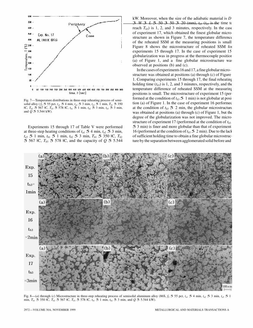
reach Th3) is 1, 2, and 3 minutes, respectively. In the case
of experiment 17, which obtained the finest globular micro-structure as shown in Figure 7, the temperature differenceof the reheated SSM at the measuring positions is small.Figure 8 shows the microstructure of reheated SSM forexperiments 15 through 17. In the case of experiment 15,globularization was in progress at the thermocouple position(a) of Figure 1, and a fine globular microstructure wasobserved at positions (b) and (c).
In the cases of experiments 16 and 17, a fine globular micro-
structure was obtained at positions (a) through (c) of Figure
1. Comparing experiments 15 through 17, the final reheating
holding time (th3) is 1, 2, and 3 minutes, respectively, and the
temperature difference of reheated SSM at the measuring
positions is small. The microstructure of experiment 15 (per-
formed at the condition of th3 5 1 min) is not globular at posi-
tion (a) of Figure 1. In the case of experiment 16 performed
at the condition of th3 5 2 min, the globular microstructure
was obtained at positions (a) through (c) of Figure 1, but the
degree of the globularization was not improved. The micro-
structure of experiment 17 (performed at the condition of th3
5 3 min) is finer and more globular than that of experiment 16 (performed at the condition of th3 5 2 min). Due to the lack
of sufficient holding time to obtain a fine globular microstruc-
ture by the separation between agglomerated solid before and
Fig. 7—Temperature distributions in three-step reheating process of semi- solid alloy ( fS 5 55 pct, ta1 5 4 min, ta2 5 3 min, ta3 5 1 min, Th1 5 350 8C, Th2 5 567 8C, Th3 5 578 8C, th1 5 1 min, th2 5 3 min, th3 5 3 min, and Q 5 5.544 kW).
Experiments 15 through 17 of Table V were performed at three-step heating conditions of ta1 5 4 min, ta2 5 3 min, ta3 5 1 min, th1 5 1 min, th2 5 3 min, Th1 5 350 8C, Th2
5 567 8C, Th3 5 578 8C, and the capacity of Q 5 5.544
Fig. 8—(a) through (c) Microstructure in three-step reheating process of semisolid aluminum alloy (86S, fS 5 55 pct, ta1 5 4 min, ta2 5 3 min, ta3 5 1 min, Th1 5 350 8C, Th2 5 567 8C, Th3 5 578 8C, th1 5 1 min, th2 5 3 min, and Q 5 5.544 kW).
2972—VOLUME 30A, NOVEMBER 1999 METALLURGICAL AND MATERIALS TRANSACTIONS A

after phase change, the reheating conditions of experiment 16 are unsuitable.
Experiments 18 and 19 of Table V were performed at the
positions is small, and in the case of experiment 18, theglobular microstructure is obtained at positions (a) through (c) in Figure 1.
Compared to experiment 17, which obtained a fine globu-lar microstructure, in the case of experiment 18, the tempera-ture difference of reheated SSM at the measuring positionsis larger. Experiment 18 shows good globularization, butshows cohesion between solid regions at positions (a) through (c) of Figure 1.
conditions of ta1 5 4 min, ta3 5 2 min, th1 5 1 min, th2 5 3 min, th3 5 2 min, Th1 5 350 8C, Th2 5 567 8C, Th3 5 578 8C, and the capacity of Q 5 5.544 kW. Moreover, when the size of the adiabatic material is D 3 W 3 L 5 50 3 50 3 20 (mm), ta2 is 3 and 4 minutes, respectively. Figure 9 showsthe microstructure of reheated SSM for experiment 18. The temperature difference of reheated SSM at the measuring
VII. SOLID FRACTION 50 PCT
Reheating experiments 20 through 28 were performed forfs 5 50 pct. From experiments 20 through 26 of Table V, the experiments are carried out at the reheating conditionsof ta1 5 4 min, ta2 5 3 min, ta3 5 1 min, th1 5 1 min, th2
5 3 min, th3 5 2 min, Th1 5 350 8C, Th2 5 572 8C, and Th3 5 582 8C, changing the capacity of the induction heatingsystem to determine the optimal capacity according to theheating time. The sizes of adiabatic materials are D 3 W 3 L 5 50 3 50 3 20 (mm) from experiments 20 through 25, and D 3 W 3 L 5 53 3 53 3 19 (mm) for experiment 26, respectively. In the case of Q 5 5.128 kW, the billet reaches the set temperature with a temperature difference of 62 8C.
The reheating experiments of experiments 27 and 28 of Table V were performed under the reheating conditions of experiment 26 with th3 5 4 min and th3 5 3 min (th3 is the final holding time in a three-step reheating), respectively. Figures 10 and 11 show the temperature distribution and microstructure of reheated SSM for experiment 28 of Table V. The temperature difference of reheated SSM at the mea- suring positions is small, and in the case of experiment 27, the globular microstructure was coarse at positions (a) through and (c) of Figure 1. However, in the case of experi- ment 28, a fine globular microstructure was obtained at positions (a) through (c). Compared to experiment 28, the microstructure of experiment 27 becomes coarse by the
Fig. 9—(a) through (c) Microstructure in three-step reheating process of semisolid aluminum alloy (experiment 18, 86S, fS 5 55 pct, ta1 5 4 min,ta2 5 3 min, ta3 5 2 min, Th1 5 350 8C, Th2 5 567 8C, Th3 5 578 8C, th1
5 1 min, th2 5 3 min, th3 5 2 min, and Q 5 5.544 kW).
Fig. 10—Temperature distributions in three-step reheating process of semi-solid aluminum alloy ( fS 5 50 pct, ta1 5 4 min, ta2 5 3 min, ta3 5 1 minTh1 5 350 8C, Th2 5 572 8C, Th3 5 582 8C, th1 5 1 min, th2 5 3 min, th3
5 3 min, and Q 5 5.544 kW).
METALLURGICAL AND MATERIALS TRANSACTIONS A VOLUME 30A, NOVEMBER 1999—2973

Fig. 11—(a) through (c) Microstructure in three-step reheating process of semisolid aluminum alloy (86S, fS 5 50 pct, ta1 5 4 min, ta2 5 3 min, ta3 5 1 min, Th1 5 350 8C, Th2 5 572 8C, Th3 5 582 8C, th1 5 1 min, th2 5 3 min, and Q 5 5.128 kW).
growth and coalescence due to longer holding time than that of experiment 28.
is not a good condition because the size of the solid grain is small, but the globularization of the microstructure is not
obtained. As shown in Figure 6, two-step reheating also is
not relevant due to the lack of sufficient holding time to
allow for the separation between solid and liquid before
and after phase change and for globularization of a small
Si particle.
The holding time of the final step is very important in
the three-step reheating process. As shown in Figures 8(a)
and (b), if the holding time of the final step is short, the
microstructure of the globularization is not obtained or not
accurate due to the lack of sufficient holding time for the
separation between a solid and a liquid, before and after
phase change, and for globularization by the growth of a
small Si primary crystal. On the other hand, if the holding
time of the final step is too long, the microstructure becomes
coarse due to the growth and coalescence of solid regions
rather than the refining of globular Si primary crystal,[22] as
shown in Figure 11(a). Therefore, the optimal holding time
of the final step to obtain a fine globular microstructure
without agglomeration is 3 minutes.
Figure 13 shows the optimal reheating conditions to obtain
a fine globular microstructure that is available for thixoform-
ing according to the alloys and specimen sizes. Compared
to the reheating conditions performed by using A356 alloys
with d 3 l 5 39 3 85 (mm) and d 3 l 5 76 3 60 (mm)
by Kang et al.[14] by whom the finest globular microstructure
is obtained in one-step reheating conditions (ta1 5 10 min, th1 5 2 min, Th1 5 5738C, Q 5 3.3 kW) for d 3 l 5 39 3 85 (mm) and in two-step reheating conditions (ta1 5 8 min,
VIII. COMPARISON BETWEEN SOLID
FRACTION 50 AND 55 PCT
Through reheating experiments for fs 5 50 and 55 pct, it was found that the higher the solid fraction, the worse the accuracy of globularization, but the boundary between the solid regions and the liquid regions is clear.
Figure 12 shows the micrographs magnified to the scale of 1000 to observe the eutectic microstructure of experiments 17 and 28, which obtained the finest globular microstructurefor fs 5 55 and 50 pct. Figures 12(a) and (b) show that theeutectic is melted completely. Therefore, it was found that the eutectic must be melted completely at over 572 8C (com-plete eutectic melting temperature of ALTHIX 86S alloy),and the reheating time for the complete eutectic melting isnecessary to obtain a fine globular microstructure. The risein temperature does not occur until a sufficient amount of thermal energy to melt the eutectic is provided because so much thermal energy and time are necessary to melt the eutectic.[14,15] Before and after the melting of the eutectic,the solid fraction changes rapidly, and a rapid temperaturerise occurs when the eutectic is melted. Due to this tempera-ture rise, controlling the reheating temperature is difficult.Therefore, to homogeneously control the temperature distri-bution and the solid fraction of the SSM, the billet must bereheated in three steps.
It was found that in the case of the ALTHIX 86S alloy with d 3 l 5 76 3 70 (mm) (Figure 5), one-step reheating
2974—VOLUME 30A, NOVEMBER 1999 METALLURGICAL AND MATERIALS TRANSACTIONS A

finest globular microstructure is obtained in three-step condi- tions (ta1 5 4 min, ta2 5 3 min, ta3 5 1 min, th1 5 1 min, th2 5 3 min, th3 5 2 min, Th1 5 3508C, Th2 5 5758C, Th3
5 5848C, Q 5 8.398 kW, and the size of the adiabatic material is D 3 W 3 L 5 53 3 53 3 19 (mm)) for fs 5 50 pct and in three-step conditions (ta1 5 4 min, ta2 5 3 min, ta3 5 1 min, th1 5 1 min, th2 5 3 min, th3 5 2 min, Th1 5 3508C, Th2 5 5708C, Th3 5 5768C, Q 5 12.04 kW, and the size of the adiabatic material is D 3 W 3 L 5 50 3 50 3 20 (mm)) for the solid fraction of fs 5 55 pct.
In this study using ALTHIX 86S alloys with d 3 l 5 76 3 70 (mm), the finest globular microstructure was obtained in three-step conditions (ta1 5 4 min, ta2 5 3 min, ta3 5 1 min, th1 5 1 min, th2 5 3 min, th3 5 3 min, Th1 5 3508C, Th2 5 5678C, Th3 5 5788C, Q 5 5.544 kW, and the size of the adiabatic material was D 3 W 3 L 5 50 3 50 3 20 (mm)) for fs 5 55 pct and in three-step conditions (ta1 5 4 min, ta2 5 3 min, ta3 5 1 min, th1 5 1 min, th2 5 3 minth3 5 3 min, Th1 5 3508C, Th2 5 5728C, Th3 5 5828C, Q 5 5.128 kW, and the size of the adiabatic material was D 3 W 3 L 5 53 3 53 3 19 (mm)) for the solid fraction of fs 5 50 pct.
IX. GRAIN GROWTH MECHANISM OF ALTHIX 86S ALLOY
In the case of eutectic Al-Si alloys, mechanical propertiessuch as wear resistance, strength, hardness, flowability athigh temperature, and corrosion resistance are excellent dueto the microstructure distributed with Si primary crystalsinside the eutectic matrix. However, a coexisting solidus-liquidus interval increases with silicon content, and themicrostructure becomes coarse when a strong electromag-netic stirring force occurs.
Therefore, it is important to prevent the coarsening (over 100 mm) of Si primary crystals for thixoforming, because, generally, an average grain size below 100 mm in the reheated state will be sufficient to ensure a homogeneous material flow of the semisolid alloy and good dimensional stability during die filling.[9–13,21]
The factor commonly used to explain the coarsening phe- nomena of the primary particles is the orientation relation- ship between particles. The experiments were performed by changing the reheating conditions such as solid fraction,
Fig. 12—(a) Exp. No. 17, f 5 55 pct, t 5 4 min, t 5 3 min, t 5 1 S a1 a2 a3
min, Th1 5 350 8C, Th2 5 567 8C, Th3 5 578 8C, th1 5 1 min, th2 5 3 min, th3 5 3 min, Q 5 5.544 kW and (b) Exp. No. 28, fS 5 50 pct, ta1 5 4 min, ta2 5 3 min, ta3 5 1 min, Th1 5 350 8C, Th2 5 572 8C, Th3 5 582 8C, th1 5 1 min, th2 5 3 min, th3 5 3 min, Q 5 5.128 kW. Eutectic microstructure of semisolid alloy (ALTHIX 86S).
ta2 5 1 min, th1 5 3 min, th2 5 2 min, Th1 5 5758C, Th2 5 5848C, Q 5 3.00 kW) for d 3 l 5 76 3 60 (mm).
According to reported results using A356 alloys with d 3 l 5 76 3 90 (mm) by Jung and co-workers,[15,21] the
Fig. 13—Input data diagram of optimal reheating conditions to obtain the globular microstructure for variation of alloys and specimen size.
METALLURGICAL AND MATERIALS TRANSACTIONS A VOLUME 30A, NOVEMBER 1999—2975

heating time, and reheating holding time. However, no change of the orientation relationship between particles was detected through experiments.
It is seen that the bonding between particles in the reheat- ing process does not occur along certain crystallographic directions but occurs in disordered directions, and the globu- larized particles are coarse due to the coalescence between particles. Therefore, to prevent the coarsening of the parti- cles, it is important to hold a relevant temperature for a constant time during each step, and in the case of three- step reheating, it is especially important in the final step. Induction heating of an aluminum billet over a diameter of 30 mm is effective at low frequencies. However, in the caseof low frequencies, if the holding time at high temperaturesis long, coarsening occurs through Ostwald growth, coales-cence, and separation processes due to a strong electromag-netic stirring force.[21,23]
In order to prevent the A356 alloy with d 3 1 5 76 3 90 (mm) from coarsening during reheating, it should be heldfor 2 minutes at 576 8C, and in the case of three-step reheat-ing, that is the holding time during the final step.[15] A356and Al2024 alloys with d 3 1 5 60 3 90 (mm) are heldfor 1 minute at 576 8C and 616 8C, respectively.[20,24] In this study, the ALTHIX 86S alloy with d 3 1 5 76 3 70 (mm) was used and held for 3 minutes at 578 8C.
Silicon primary crystals are simultaneously destroyed and coalesced by collisions between themselves, resulting in polycrystals with low-and high-angle boundaries. Further- more, after the fracture and coalescence processes progress, the interface of Si primary crystals are gradually rounded by their collisions.[21,25] The fracture, coalescence, and wear of Si primary particles occur compositively, and the initial facet Si particle is globularized at the end of induction heating.
Research on the globularization phenomena beside a coex- isting solidus-liquidus interval has focused mainly on alloys with a nonfaceted interface. In the case of the Al2024 alloy with a nonfaceted interface, the interfacial energy between solid and liquid does not change for the variation of crystallo- graphic directions.[21,26]
However, in the ALTHIX 86S alloy with a faceted inter- face, the flat interface is a simple cubic crystal surrounded by a dense facet with a lower interfacial energy because the interfacial energy between solid and liquid changes for
variations of crystallographic directions.[21,25] Therefore, it is seen that during the solidification of alloys, the globulari- zation of alloys with a faceted interface such as Si primary crystals of the ALTHIX 86S alloy can occur due to the higher entropy of the interfacial energy compared to alloys with a nonfaceted interface. This is due to the greater differ-
ence in structure and bonding between the solid and liquid phases as compared to metals, which exhibit only very small differences between the two phases. More research on the
deformation behavior in the reheating process of eutectic alloys is necessary.
Currently, research, development, and application for thix- oforming are limited to a few casting alloys such as A356 and A357 classified into Al-Si-Mg alloy group. However, it is seen that with the increasingly widespread use of thixo-
forming parts, the development of a tailored alloy for a specific application has to be chosen. Therefore, in this study, the effect of the induction heating conditions of the ALTHIX
86S alloy on globular microstructure, grain growth, and theprevention of coarsening was researched. The ALTHIX 86Salloy contains the composition of Al-6 pct Si-3 pct Cu-0.3 pct Mg and strengthens by age hardening.
In the case of ALTHIX 86S, segregation in which siliconand copper are the principal alloying elements often occursas a defect in the forming process.[21,27,28] However, a uni-form microstructure without segregation can be obtained in the thixoforming process.
In this study, because a fine and completely melted eutec-tic Si phase of ALTHIX 86S was obtained, it is expectedthat thixoforming parts with good mechanical properties willbe produced.
X. CONCLUSIONS
To apply the thixoforging and semisolid die casting pro-cesses, the optimal coil design of ALTHIX 86S alloys withd 3 1 5 76 3 70 (mm) was theoretically proposed andmanufactured. The suitability of the coil design was demon-strated by conducting induction-heating experiments. Basedon the experiment, the following can be summarized.
1. For the ALTHIX 86S billet with d 3 1 5 76 3 70 (mm)(the frequency of the induction heating system: 60 Hz) often used in the thixoforming process, the optimal coil design for induction heating was proposed.
2. This study shows that the larger the billet size, the betterthe multistep reheating compared with reported results,and the heating time and the capacity of the induction heating system must be increased. We could see that thefinal holding time of 3 minutes is suitable to secure a globular microstructure.
3. If the reheating holding time of the final step is too short,a globular microstructure cannot be obtained and, if theholding time is too long, because the risks of grain coars-ening may be increased. A fine globular microstructureis obtained with a holding time of 3 minutes at the three-step reheating process.
REFERENCES
1. R. Sebus and G. Henneberger: Proc. 5th Int. Conf. on Semi-SolidProcessing of Alloys and Composites, Golden, CO, June 1998, A.K.Bhasin, J.J. Moore, K.P. Young, and S. Midson, eds., Colorado Schoolof Mines, Golden, CO, 1998, pp. 481-87.
2. F. Matsuura and S. Kitamura: Proc. 5th Int. Conf. on Semi-SolidProcessing of Alloys and Composites, Golden, CO, June 1998, A.K. Bhasin, J.J. Moore, K.P. Young, and S. Midson, eds. Colorado Schoolof Mines, Golden, CO, 1998, pp. 489-96.
3. S. Midson, V. Rudnev, and R. Gallik: Proc. 5th Int. Conf. on Semi-Solid Processing of Alloys and Composites, Golden, CO, June 1998,A.K. Bhasin, J.J. Moore, K.P. Young, and S. Midson, eds., ColoradoSchool of Mines, Golden, CO, 1998, pp. 497-504.
4. V.I. Rudnev, R.L. Cook, D.L. Loveless, and M.R. Black: Steel Heat Treatment Handbook, Marcel Dekker Inc., New York, NY, 1997, pp. 794-857.
5. V.I. Rudnev and R. L. Cook: Forging Mag., 1995, Winter, pp. 27-30.
2976—VOLUME 30A, NOVEMBER 1999 METALLURGICAL AND MATERIALS TRANSACTIONS A

6. V.S. Nemkov, V.B. Demidovich, V.I. Rudnev, and O. Fishman: Proc. XIIth Electroheat Congress ELECTROTECH 92, Montreal, 1992,
IEEE and EMC Society, Montreal, 1992, pp. 180-88. 7. V.I. Rudnev and D.L. Loveless: Industrial Heating, 1995, Jan., part
1, pp. 29-34. 8. G. Wan, T. Witulski, and G. Hirt: Int. Conf. on Aluminium Alloys:
New Process Technologies, Marina di Ravenna, June 1993. 9. T. Witulski, U. Morjan, I. Niedick, and G. Hirt: Proc. 5th Int. Conf.
on Semi-Solid Processing of Alloys and Composites, Golden, CO, June 1998, A.K. Bhasin, J.J. Moore, K.P. Young, and S. Midson, eds., Colorado School of Mines, Golden, CO, 1998, pp. 353-60.
10. M. Garat, S. Blais, C. Pluchon, and W.R. Loue’: Proc. 5th Int. Conf. on Semi-Solid Processing of Alloys and Composites, Golden, CO, June 1998, A.K. Bhasin, J.J. Moore, K.P. Young, and S. Midson, eds., Colorado School of Mines, Golden, CO, 1998, pp. xvii-xxxi.
11. C. Pluchon, W. Loue’ and M. Garat: Proc. Symp. on Forming Technol- ogy of Semi-Solid Metals, Pusan, Nov. 1997, C.G. Kang, ed., KSTP and KIMM, Pusan National University, Pusan, 1997, pp. 80-95.
12. W. Loue’ and M. Garat: Proc. Symp. on Forming Technology of Semi- Solid Metals, Pusan, Nov. 1997, C.G. Kang, ed., KSTP and KIMM, Pusan National University, Pusan, 1997, pp. 96-104.
13. M. Garat: Proc. Symp. on Forming Technology of Semi-Solid Metals, Pusan, Nov. 1997, C.G. Kang, ed., KSTP and KIMM, Pusan NationalUniversity, Pusan, 1997, pp. 105-13.
14. C.G. Kang, Y.J. Do, and S.S. Kang: J. Kor. Soc. Technol. Plasticity, 1998, vol. 7 (3), pp. 215-24.
15. H.K. Jung and C.G. Kang: J. Kor. Foundrymen’s Soc., 1998, vol. 18 (5), pp. 450-61.
16. E.J. Davies: Conduction and Induction Heating, Peter Peregrinus Ltd., London, 1990, pp. 100, 164-79, and 202-22.
17. N.R. Stansel: Induction Heating, McGraw-Hill, New York, NY, 1949, p. 178.
18. V.I. Rudnev, L.C. Raymond, D.L. Loveless, and M.R. Black: Induction
Heat Treatment, Marcel Dekker Inc., New York, NY, 1997, pp. 775-911.
19. Metals Handbook: Properties and Selection: Nonferrous Alloys and Special Purpose Materials, 10th ed., ASM INTERNATIONAL, Mate- rials Park, OH, 1990, vol. 2, pp. 164-66.
20. C.G. Kang, H.K. Jung, and Y.J. Jung: Proc. 6th Int. Conf. on Technologyof Plasticity (ICTP), Nuremberg, Sept. 1999, M. Geiger, ed., VDI andWGP, Friedrich-Alexander-University, Nuremberg, Germany, 1999,in press.
21. C.G. Kang, Y.H. Kim, and H.K. Jung: “Thixoforming Process Devel-opment of Aluminum Materials,” Technical Report No. NSDM 98K3- 0908-01-01-3, Engineering Research Center for Net Shape and Die Manufacturing, Pusan National University, Pusan, 1999.
22. C.G. Kang, H.K. Jung, and N.S. Kim: Int. J. Mech. Sci., 1999, vol. 41(12), pp. 1423-45.
23. I.J. Kim and D.H. Kim: J. Kor. Foundrymen’s Soc., 1997, vol. 17(4),
pp. 311-18. 24. C.G. Kang and J.Y. Kang: “The Process Development on Thixoforming
of Aluminium Materials,” Technical Report, No. NSDM 97K3-0908- 01-01-3, Engineering Research Center for Net Shape and Die Manufac- turing, Pusan National University, Pusan, Feb. 1998.
25. W. Kurz and D.J. Fisher: Fundamentals of Solidification, Trans Tech Publications, Aedermannsdorf Switzerland, 1984, pp. 34-43.
26. G. Hirt, R. Cremer, A. Winkelmann, T. Witulski, and M. Zillgen: J. Mater. Processing Technol., 1994, vol. 45, pp. 359-64.
27. C.G. Kang, K.D. Jung, and H.K. Jung: Proc. 2nd Int. Conf. on Intelli-
gent Processing and Manufacturing of Materials (IPMM), Honolulu, Hawaii, July 1999, J.A. Meech, M.M. Veiga, M.H. Smith, and S.R. LeClair, eds., West Coast Reproduction Centers, Vancouver, B.C., 1999, pp. 593-99.
28. S. Kouji: Proc. 175th JSTP Symp. for Semi-Solid Metals Forming, Tokyo, May 1997, M. Kiuchi, ed., JSTP and JSME, Tokyo University of Technology, Tokyo, 1997, pp. 25-33.
METALLURGICAL AND MATERIALS TRANSACTIONS A VOLUME 30A, NOVEMBER 1999—2977