
Induction Heating Devices HEATER - Schaeffler Group · The induction heating devices HEATER50,...
80
Induction Heating Devices HEATER User manual
Transcript of Induction Heating Devices HEATER - Schaeffler Group · The induction heating devices HEATER50,...

Induction Heating DevicesHEATER
User manual

Foreword
The induction heating devices HEATER50, HEATER100, HEATER200, HEATER400, HEATER800 and HEATER1600 give rapid, clean oper-ation. Their high efficiency level allows energy-efficient heating and shorter heating times. This reduces the operating costs. The uniform, controlled heating allows consistently good quality of mounting.Operation is simple and user-friendly, the touch-sensitive screen is oil-resistant, dustproof and waterproof.When heating by induction is used, there is no need at all to useoil – this gives particularly good environmental compatibility.The scope of application is very extensive. It is possible to heatthe loose inner rings of cylindrical or needle roller bearings as well as sealed and greased bearings. Compared with previous models, further improvements have been made in performance capacity and safety and the part to be heated need no longer be of a minimum mass.In order to ensure durability in demanding industrial operation,the devices are extremely robust and reliable.
Current version An induction heating unit is controlled by means of an operatorunit with a touch-sensitive screen. The operator software can be developed further and an update is possible free of charge.Changes to the software can lead to adjustments in the user manual. A current version of this user manual can be found athttp://medien.schaeffler.com using the search term BA42.
ST4_17980348043_vorwort.fm Seite 1 Mittwoch, 6. Dezember 2017 9:02 09
2 BA42 Schaeffler Technologies
Page
Contents
About the user manual Symbols .................................................................................... 4
Signs......................................................................................... 4
Availability ................................................................................ 5
Legal guidelines ........................................................................ 5
Original user manual ................................................................. 5
General safety guidelines Usage for the intended purpose ................................................. 6
Usage not for the intended purpose ........................................... 6
Qualified personnel ................................................................... 6
Hazards..................................................................................... 7
Safety devices ........................................................................... 8
Protective equipment ................................................................ 9
Safety regulations ..................................................................... 10
Scope of delivery ................................................................................................. 12
Accessories............................................................................... 17
Damage during transit ............................................................... 17
Defects...................................................................................... 17
Description Overview ................................................................................... 18
Temperature sensor................................................................... 19
Function .................................................................................... 20
Operation.................................................................................. 21
Operating modes....................................................................... 22
Temperature holding mode ........................................................ 26
Transport and storage Transport................................................................................... 27
Storage ..................................................................................... 31
Commissioning Hazard area............................................................................... 32
Initial stages ............................................................................. 33
Voltage supply .......................................................................... 33
Configuration ............................................................................ 35
ST4_9007217199014411_teil_ivz.fm Seite 2 Mittwoch, 6. Dezember 2017 9:02 09
Schaeffler Technologies BA42 3
PageOperation Selecting a heating device ........................................................ 47
Selecting a support ledge.......................................................... 47
Changing the slewing ledge ...................................................... 48
Changing the vertical ledge ....................................................... 49
Positioning the rolling bearing .................................................. 50
Connecting the temperature sensor........................................... 54
Selecting the heating method ................................................... 56
Setting values........................................................................... 57
Heating..................................................................................... 58
Cancelling temperature hold ..................................................... 59
Removing the temperature sensor ............................................. 60
Removing the rolling bearing..................................................... 61
Saving the heating curve........................................................... 65
Troubleshooting Eliminating a malfunction ......................................................... 66
General errors........................................................................... 66
Repair....................................................................................... 66
Difficult malfunctions................................................................ 67
Simple malfunctions ................................................................. 67
Maintenance Maintenance plan ..................................................................... 68
Decommissioning ................................................................................................ 69
Disposal Regulations .............................................................................. 69
Technical data and accessories HEATER50................................................................................. 70
HEATER100............................................................................... 71
HEATER200............................................................................... 72
HEATER400............................................................................... 73
HEATER800............................................................................... 74
HEATER1600............................................................................. 75
Original accessories.................................................................. 75
Appendix EU Declaration of Conformity..................................................... 76
ST4_9007217199014411_teil_ivz.fm Seite 3 Mittwoch, 6. Dezember 2017 9:02 09
4 BA42 Schaeffler Technologies
HEATER50, HEATER100, HEATER200, HEATER400, HEATER800, HEATER1600
About the user manual This user manual is part of the device and contains important information.
Symbols The warning and hazard symbols are defined in accordance with ANSI Z535.6-2006.
DANGER In case of non-compliance, death or serious injury will occur.
WARNING In case of non-compliance, death or serious injury may occur.
NOTICE In case of non-compliance, damage or malfunctions in the product or the adjacent construction will occur.
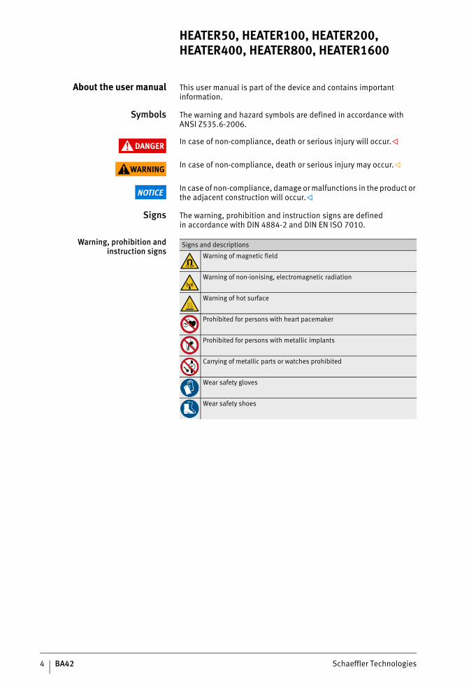
Signs The warning, prohibition and instruction signs are definedin accordance with DIN 4884-2 and DIN EN ISO 7010.
Warning, prohibition andinstruction signs
Signs and descriptions
Warning of magnetic field
Warning of non-ionising, electromagnetic radiation
Warning of hot surface
Prohibited for persons with heart pacemaker
Prohibited for persons with metallic implants
Carrying of metallic parts or watches prohibited
Wear safety gloves
Wear safety shoes
ST4_27021615709080203_anleitun.fm Seite 4 Mittwoch, 6. Dezember 2017 9:02 09
Schaeffler Technologies BA42 5
Availability This user manual is supplied with each device and can also be ordered retrospectively.
WARNING If the user manual is missing, incomplete or illegible, the user may make errors.The Safety Officer must ensure that this user manual is always complete and legible and that any persons using the device havethe user manual available.
Legal guidelines The information in this manual corresponded to the most recent status at the close of editing. The illustrations and descriptions cannot be used as grounds for any claims relating to devices that have already been delivered. Schaeffler Technologies AG & Co. KG accepts no liability for any damage or malfunctions if the device or accessories have been modified or used in an incorrect manner.
Original user manual The original user manual is taken to be a user manual inthe German language. A user manual in another language is to be taken as a translation of the original user manual.
ST4_27021615709080203_anleitun.fm Seite 5 Mittwoch, 6. Dezember 2017 9:02 09
6 BA42 Schaeffler Technologies
HEATER50, HEATER100, HEATER200, HEATER400, HEATER800, HEATER1600
General safety guidelines A description is given of how the device may be used, who may use the device and what must be observed when using the device.
Usage for the intendedpurpose
Correct usage of the induction heating device is defined asthe industrial heating of rolling bearings and other rotationally sym-metrical, ferromagnetic workpieces. Sealed and greased rolling bearings can also be heated. In this case, the maximum permissible heating temperatures for the seal and grease must be observed.
Usage not for the intendedpurpose
The heating device may not be used for the heating of parts thatare not ferromagnetic or not rotationally symmetrical. Do not use the heating device in an environment with a risk of explosion.Usage not for the intended purpose can lead to the injury or death of persons or damage to the device.
Qualified personnel For safety reasons, the heating device may only be operated by qualified personnel.A person defined as qualified personnel:■ has all the necessary knowledge■ is aware of all the hazards and safety guidelines■ is authorised to use the heating device by the safety co-ordinator■ has fully read and understood this user manual.
Work on electrical devices The heating device HEATER1600 may only be connected by a trained electrician. The switch cabinet may only be opened by an electrician. Only an electrician is in a position, on the basis of his technical training, knowledge and experience as well as his knowledge ofthe appropriate regulations, to carry out work on electrical devices correctly and recognise possible hazards.
ST4_27021615709080203_anleitun.fm Seite 6 Mittwoch, 6. Dezember 2017 9:02 09
Schaeffler Technologies BA42 7
Hazards During operation, the device always generates an electromagnetic field. The electromagnetic field heats ferromagnetic parts andcan disrupt or destroy electronic components.Examples include watches, clocks, mobile telephones, credit cards and other data carriers as well as electronic circuits.
DANGER Danger of heart stoppage in persons fitted with a pacemaker due to the strong electromagnetic field.Persons fitted with a pacemaker must remain outside the hazard area of the heating device, see page 32.
WARNING Danger of death for persons with artificial heart valves madefrom metal, hazard of severe burns due to heating of implants bythe electromagnetic field.Persons with ferromagnetic implants must remain outsidethe hazard area of the heating device, see page 32.
Implants Persons with implants must clarify with a doctor whetherthe implants are ferromagnetic before working with an induction heating device. The following list is not exhaustive but is intended to give the useran initial overview of the types of implants that may be hazardous:■ artificial heart valve■ ICD■ stent■ hip implant■ knee implant■ metal plate■ metal screw■ dental implant and dentures■ cochlear implant■ neurostimulator■ insulin pump■ hand prosthesis■ subcutaneous piercing.
ST4_27021615709080203_anleitun.fm Seite 7 Mittwoch, 6. Dezember 2017 9:02 09
8 BA42 Schaeffler Technologies
HEATER50, HEATER100, HEATER200, HEATER400, HEATER800, HEATER1600
Metallic objects Persons with a metallic object must clarify whether it is ferro-magnetic before working with an induction heating device.The following list is not exhaustive but is intended to givethe user an initial overview of the types of metallic objects thatmay be hazardous:■ prosthetic■ spectacles■ hearing aid■ earring■ piercing■ brace■ chain■ ring■ armband■ keys■ timepiece■ coin■ ballpoint pen, fountain pen■ belt■ shoes with metal caps or metal springs in the sole.
Safety devices In order to protect the user and the heating device, the following safety devices are present:■ The temperatures of the cooling element, coil and housing are
continuously monitored. The thermal protection system will switch off the heating device before any component is over-heated. Once the thermal protection system has been triggered, the heating device can be put back into operation once the error has been eliminated and the device has been checked.
■ The heating of the rolling bearing is continuously monitored.If the specified increase in temperature is not achieved within a certain period, the heating device is switched off by the software.
ST4_27021615709080203_anleitun.fm Seite 8 Mittwoch, 6. Dezember 2017 9:02 09
Schaeffler Technologies BA42 9
Operation In order that the user can move out of the hazard area beforethe electromagnetic field is generated, the following operating options are available:■ The operator can set the time on the heating device that
is counted down after pressing the START/STOP key beforethe electromagnetic field is generated. The user can then move out of the hazard area within the countdown time.
WARNING Risk of damage to health from remaining in a strong electromagnetic field, since the device starts the heating operation unexpectedly.Set a sufficiently long countdown time in order to allow exit fromthe hazard area.
Activity display During the heating operation, an animation with a red rectangle is visible. The user can thus recognise during heating when the electro-magnetic field is being generated. During demagnetisation,the electromagnetic field is indicated by a red circle with a white exclamation mark.
Protective equipment Personal protective equipment is intended to protect operating personnel against health hazards. This comprises safety shoes and gloves that are heat-resistant up to +250 °C and these must be used in the interests of personal safety.
ST4_27021615709080203_anleitun.fm Seite 9 Mittwoch, 6. Dezember 2017 9:02 09
10 BA42 Schaeffler Technologies
HEATER50, HEATER100, HEATER200, HEATER400, HEATER800, HEATER1600
Safety regulations The following safety regulations must be observed whenworking with the heating device. Further guidance on hazards and specific guidelines for action can be found, for example,in the section Operation, page 47.
Transport The heating device must not be moved directly after heating.
Storage The heating device must always be stored under the following ambient conditions:■ humidity max. 90%, non-condensing■ protected against sunlight and UV radiation■ no explosion risk in the environment■ no aggressive chemicals in the environment■ temperature from –40 °C to +40 °C.If the heating device is stored under unsuitable ambient conditions, this will probably have consequences such as damage tothe electronic unit, corrosion of the ground contact surfaces and deformation of the plastic housing.
Commissioning The heating device must not be modified.The heating device may only be commissioned if it fulfilsthe regulations to be adhered to at the place of use.Only original accessories and replacement parts may be used.The heating device may only be used in well ventilated rooms.Do not feed the mains connection cable through the U-shaped core.
ST4_27021615709080203_anleitun.fm Seite 10 Mittwoch, 6. Dezember 2017 9:03 09
Schaeffler Technologies BA42 11
Operation The heating device may only be operated under the following ambient conditions:■ closed room■ subsurface flat and capable of supporting loads■ humidity min. 5%, max. 90%, non-condensing■ no explosion risk in the environment■ no aggressive chemicals in the environment■ temperature from 0 °C to +40 °C.If the heating device is operated under unsuitable ambient conditions, this can have consequences such as damage tothe electronic unit, corrosion of the ground contact surfaces and deformation of the plastic housing.The heating device may only be operated at the correct supply voltage.Workpieces must not be heated if they are covered.Workpieces must not be heated if they exceed the maximum permissible mass, see table, page 47.Workpieces must not be suspended from ropes or chains madefrom ferromagnetic material while they are heated.During the heating process, the user must maintain a distance of at least 2 m from the heating device.Objects made from ferromagnetic material must be kept ata distance of at least 1 m from the heating device.Support, slewing and vertical ledges must not be produced independently.The heating device may only be switched on if the support,slewing or vertical ledge is correctly positioned.The support, slewing or vertical ledge must never be removed during the heating process.The heating device must not be switched off by means of the main switch while the device is heating a component.Any smoke or vapour occurring during the heating process must not be inhaled.The heating device must be switched off using the main switchif it is not in use.
WARNING Back injuries due to incorrect handling of heavy rolling bearings.In the case of heavy rolling bearings, use suitable lifting gear.
ST4_27021615709080203_anleitun.fm Seite 11 Mittwoch, 6. Dezember 2017 9:03 09
12 BA42 Schaeffler Technologies
HEATER50, HEATER100, HEATER200, HEATER400, HEATER800, HEATER1600
Maintenance The heating device must be switched off before maintenance is carried out.
Disposal Locally applicable regulations must be observed.
Conversion The heating device must not be converted.
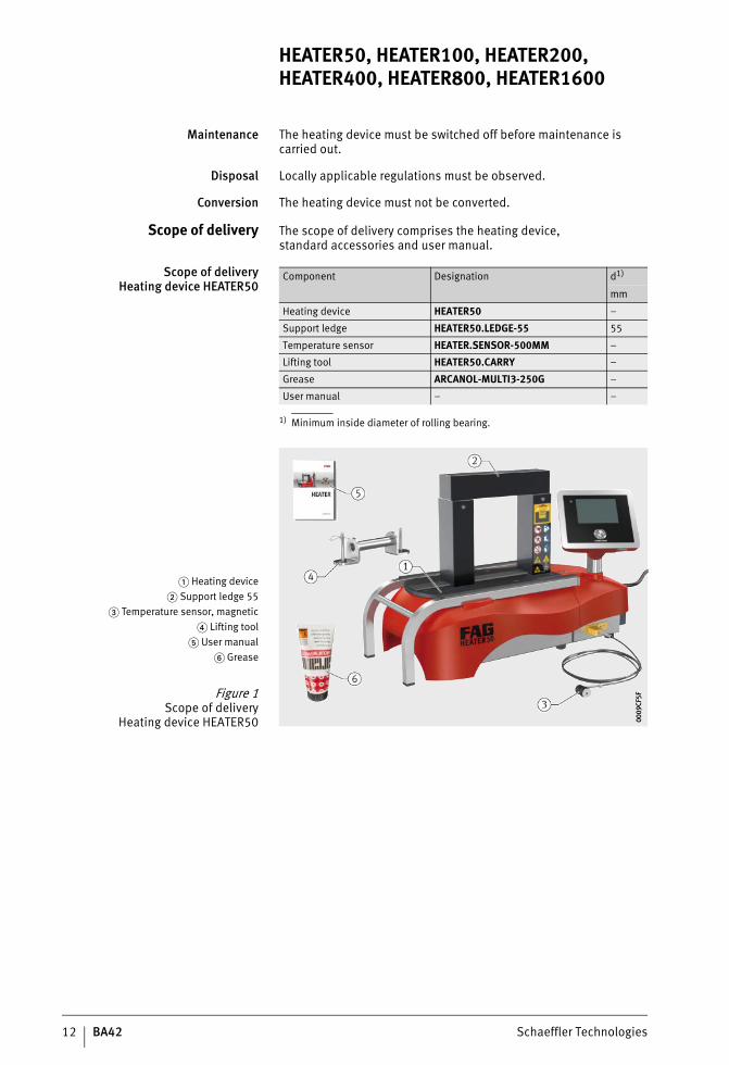
Scope of delivery The scope of delivery comprises the heating device,standard accessories and user manual.
Scope of deliveryHeating device HEATER50
1) Minimum inside diameter of rolling bearing.
Component Designation d1)
mm
Heating device HEATER50 –
Support ledge HEATER50.LEDGE-55 55
Temperature sensor HEATER.SENSOR-500MM –
Lifting tool HEATER50.CARRY –
Grease ARCANOL-MULTI3-250G –
User manual – –
� Heating device� Support ledge 55
� Temperature sensor, magnetic� Lifting tool
� User manual� Grease
Figure 1Scope of delivery
Heating device HEATER50 0009
CF5F
0009
CF5F
ST4_27021615709080203_anleitun.fm Seite 12 Mittwoch, 6. Dezember 2017 9:03 09
Schaeffler Technologies BA42 13
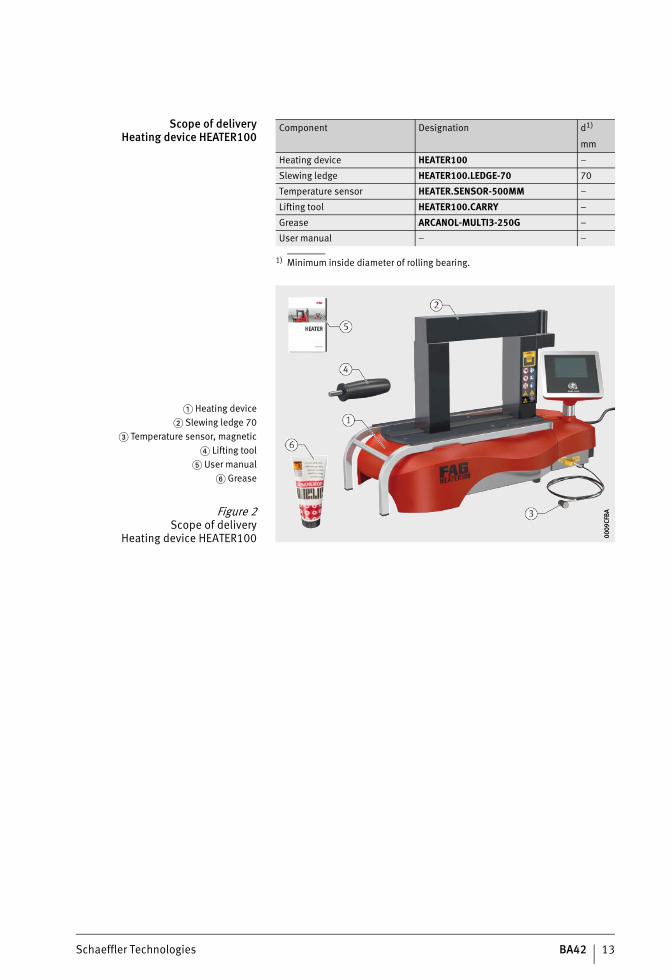
Scope of deliveryHeating device HEATER100
1) Minimum inside diameter of rolling bearing.
Component Designation d1)
mm
Heating device HEATER100 –
Slewing ledge HEATER100.LEDGE-70 70
Temperature sensor HEATER.SENSOR-500MM –
Lifting tool HEATER100.CARRY –
Grease ARCANOL-MULTI3-250G –
User manual – –
� Heating device� Slewing ledge 70
� Temperature sensor, magnetic� Lifting tool
� User manual� Grease
Figure 2Scope of delivery
Heating device HEATER100 0009
CFBA
0009
CFBA
ST4_27021615709080203_anleitun.fm Seite 13 Mittwoch, 6. Dezember 2017 9:03 09
14 BA42 Schaeffler Technologies
HEATER50, HEATER100, HEATER200, HEATER400, HEATER800, HEATER1600
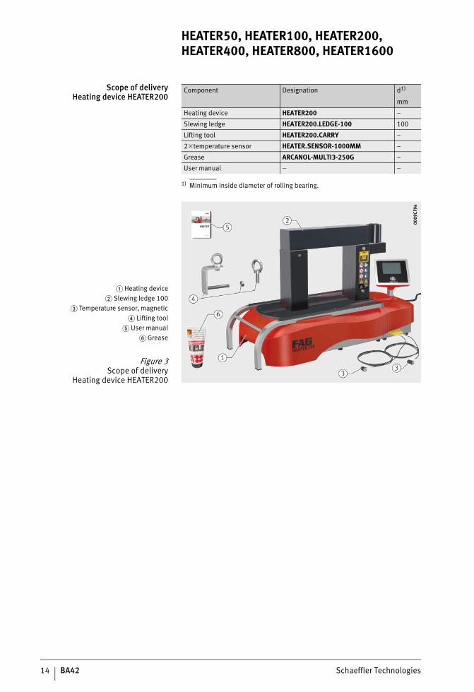
Scope of deliveryHeating device HEATER200
1) Minimum inside diameter of rolling bearing.
Component Designation d1)
mm
Heating device HEATER200 –
Slewing ledge HEATER200.LEDGE-100 100
Lifting tool HEATER200.CARRY –
2�temperature sensor HEATER.SENSOR-1000MM –
Grease ARCANOL-MULTI3-250G –
User manual – –
� Heating device� Slewing ledge 100
� Temperature sensor, magnetic� Lifting tool
� User manual� Grease
Figure 3Scope of delivery
Heating device HEATER200
0009
CF94
0009
CF94
ST4_27021615709080203_anleitun.fm Seite 14 Mittwoch, 6. Dezember 2017 9:03 09
Schaeffler Technologies BA42 15
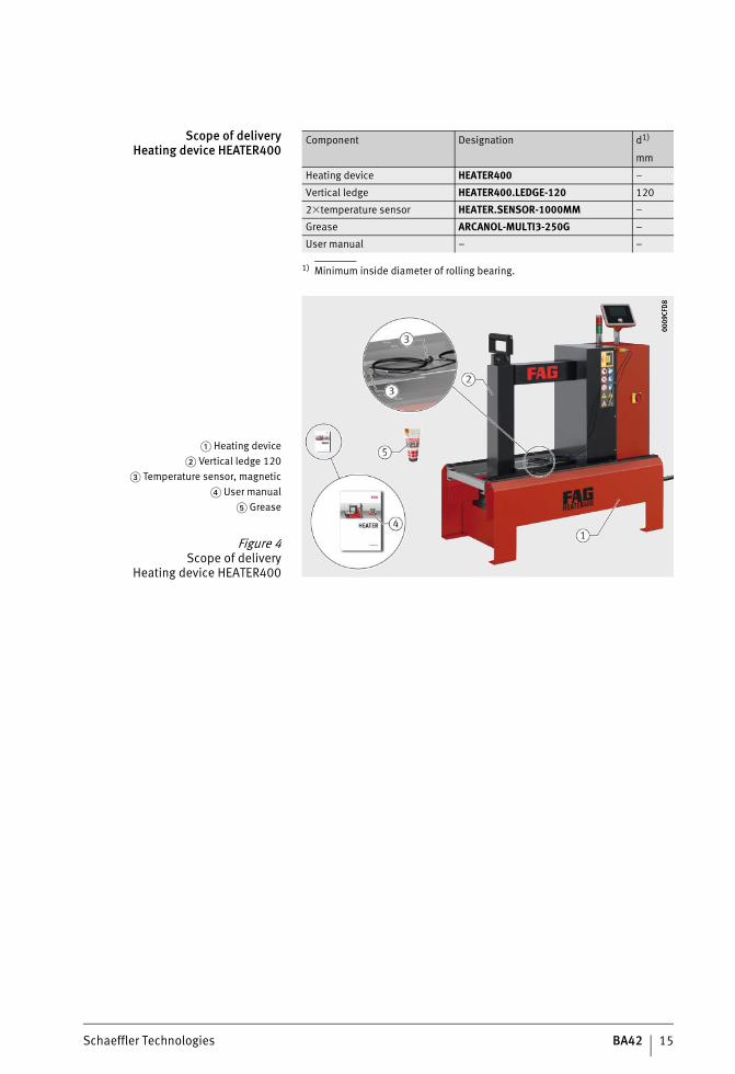
Scope of deliveryHeating device HEATER400
1) Minimum inside diameter of rolling bearing.
Component Designation d1)
mm
Heating device HEATER400 –
Vertical ledge HEATER400.LEDGE-120 120
2�temperature sensor HEATER.SENSOR-1000MM –
Grease ARCANOL-MULTI3-250G –
User manual – –
� Heating device� Vertical ledge 120
� Temperature sensor, magnetic� User manual
� Grease
Figure 4Scope of delivery
Heating device HEATER400
0009
CFD
800
09CF
D8
ST4_27021615709080203_anleitun.fm Seite 15 Mittwoch, 6. Dezember 2017 9:03 09
16 BA42 Schaeffler Technologies
HEATER50, HEATER100, HEATER200, HEATER400, HEATER800, HEATER1600
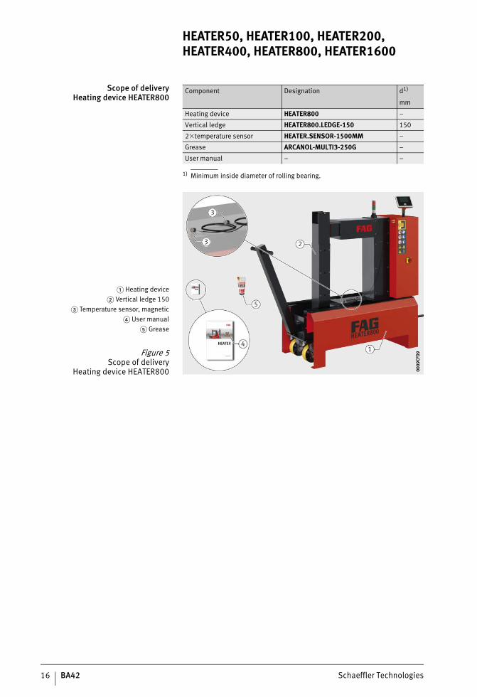
Scope of deliveryHeating device HEATER800
1) Minimum inside diameter of rolling bearing.
Component Designation d1)
mm
Heating device HEATER800 –
Vertical ledge HEATER800.LEDGE-150 150
2�temperature sensor HEATER.SENSOR-1500MM –
Grease ARCANOL-MULTI3-250G –
User manual – –
� Heating device� Vertical ledge 150
� Temperature sensor, magnetic� User manual
� Grease
Figure 5Scope of delivery
Heating device HEATER800 0009
CFD9
0009
CFD9
ST4_27021615709080203_anleitun.fm Seite 16 Mittwoch, 6. Dezember 2017 9:03 09
Schaeffler Technologies BA42 17
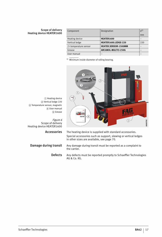
Scope of deliveryHeating device HEATER1600
1) Minimum inside diameter of rolling bearing.
Accessories The heating device is supplied with standard accessories.Special accessories such as support, slewing or vertical ledgesin other sizes are available, see page 70.
Damage during transit Any damage during transit must be reported as a complaint tothe carrier.
Defects Any defects must be reported promptly to Schaeffler Technologies AG & Co. KG.
Component Designation d1)
mm
Heating device HEATER1600 –
Vertical ledge HEATER1600.LEDGE-220 220
2�temperature sensor HEATER.SENSOR-1500MM –
Grease ARCANOL-MULTI3-250G –
User manual – –
� Heating device� Vertical ledge 220
� Temperature sensor, magnetic� User manual
� Grease
Figure 6Scope of delivery
Heating device HEATER1600 0009
CFDC
0009
CFDC
ST4_27021615709080203_anleitun.fm Seite 17 Mittwoch, 6. Dezember 2017 9:03 09
18 BA42 Schaeffler Technologies
HEATER50, HEATER100, HEATER200, HEATER400, HEATER800, HEATER1600
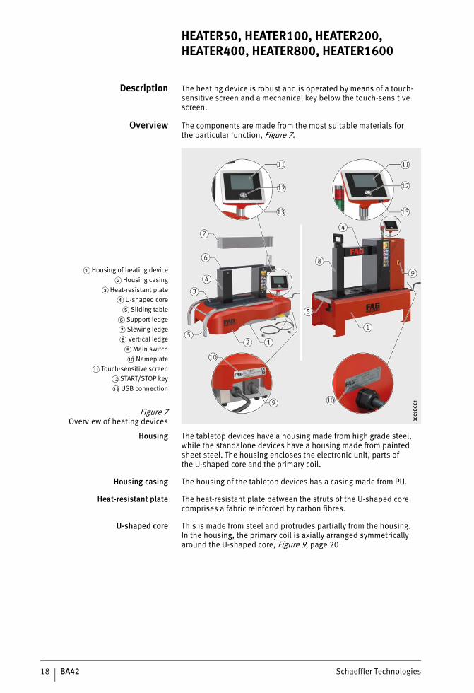
Description The heating device is robust and is operated by means of a touch-sensitive screen and a mechanical key below the touch-sensitive screen.
Overview The components are made from the most suitable materials forthe particular function, Figure 7.
Housing The tabletop devices have a housing made from high grade steel, while the standalone devices have a housing made from painted sheet steel. The housing encloses the electronic unit, parts ofthe U-shaped core and the primary coil.
Housing casing The housing of the tabletop devices has a casing made from PU.
Heat-resistant plate The heat-resistant plate between the struts of the U-shaped core comprises a fabric reinforced by carbon fibres.
U-shaped core This is made from steel and protrudes partially from the housing.In the housing, the primary coil is axially arranged symmetrically around the U-shaped core, Figure 9, page 20.
� Housing of heating device� Housing casing
� Heat-resistant plate� U-shaped core
� Sliding table� Support ledge� Slewing ledge Vertical ledge
Main switch�� Nameplate
� Touch-sensitive screen�� START/STOP key�� USB connection
Figure 7Overview of heating devices 00
09D
CC2
0009
DCC
2
ST4_27021615709080203_anleitun.fm Seite 18 Mittwoch, 6. Dezember 2017 9:03 09
Schaeffler Technologies BA42 19
Sliding table The tabletop devices have a sliding table made from high grade steel, while the standalone devices have a sliding table made from painted sheet steel. In the case of HEATER800 and HEATER1600,the sliding table has wheels and a grip for screw mounting. It has support strips made from silicone.
Support ledge This is made from the same material as the U-shaped core.The support ledge is not guided and is laid on the two upper ends of the U-shaped core.
Slewing ledge This is made from the same material as the U-shaped core.The slewing ledge is fitted on the locating stud and is slewed onthe U-shaped core.
Vertical ledge This is made from the same material as the U-shaped core.The vertical ledge is guided at the top end of the U-shaped core and can be lifted and changed.
Main switch This is used to switch the heating device on and off.
Touch-sensitive screen The heating device is adjusted, started and stopped by means ofthe touch-sensitive screen mounted on the housing.
USB connection A USB stick can be connected to the USB connector. This can be used to update firmware and import menu languages.
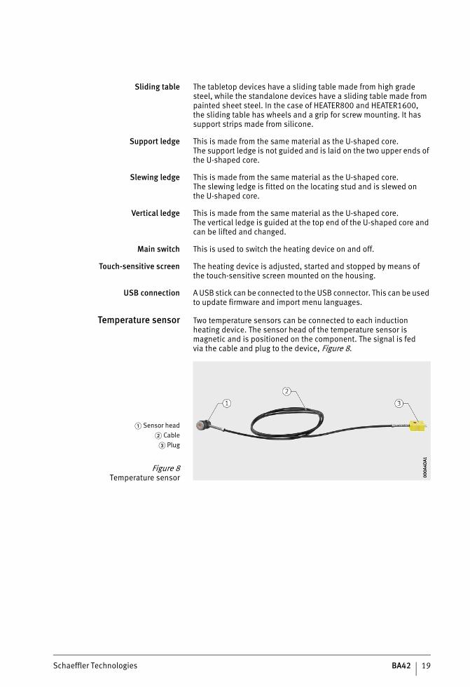
Temperature sensor Two temperature sensors can be connected to each induction heating device. The sensor head of the temperature sensor is magnetic and is positioned on the component. The signal is fedvia the cable and plug to the device, Figure 8.
� Sensor head� Cable
� Plug
Figure 8Temperature sensor 00
0A4D
A100
0A4D
A1
ST4_27021615709080203_anleitun.fm Seite 19 Mittwoch, 6. Dezember 2017 9:03 09
20 BA42 Schaeffler Technologies
HEATER50, HEATER100, HEATER200, HEATER400, HEATER800, HEATER1600
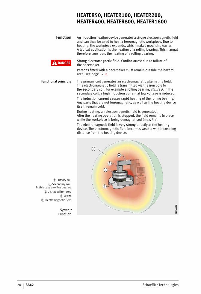
Function An induction heating device generates a strong electromagnetic field and can thus be used to heat a ferromagnetic workpiece. Due to heating, the workpiece expands, which makes mounting easier.A typical application is the heating of a rolling bearing. This manual therefore considers the heating of a rolling bearing.
DANGER Strong electromagnetic field. Cardiac arrest due to failure ofthe pacemaker.Persons fitted with a pacemaker must remain outside the hazard area, see page 32.
Functional principle The primary coil generates an electromagnetic alternating field.This electromagnetic field is transmitted via the iron core tothe secondary coil, for example a rolling bearing, Figure 9. In the secondary coil, a high induction current at low voltage is induced.The induction current causes rapid heating of the rolling bearing.Any parts that are not ferromagnetic, as well as the heating device itself, remain cold.During heating, an electromagnetic field is generated.After the heating operation is stopped, the field remains in place while the workpiece is being demagnetised (max. 5 s).The electromagnetic field is very strong directly at the heating device. The electromagnetic field becomes weaker with increasing distance from the heating device.
� Primary coil� Secondary coil,
in this case a rolling bearing� U-shaped iron core
� Ledge� Electromagnetic field
Figure 9Function 00
09AB
D6
0009
ABD
6
ST4_27021615709080203_anleitun.fm Seite 20 Mittwoch, 6. Dezember 2017 9:04 09
Schaeffler Technologies BA42 21
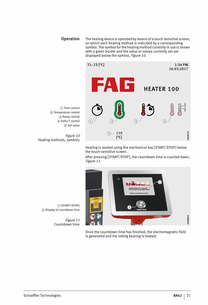
Operation The heating device is operated by means of a touch-sensitive screen, on which each heating method is indicated by a corresponding symbol. The symbol for the heating method currently in use is shown with a green border and the value or values currently set are displayed below the symbol, Figure 10.
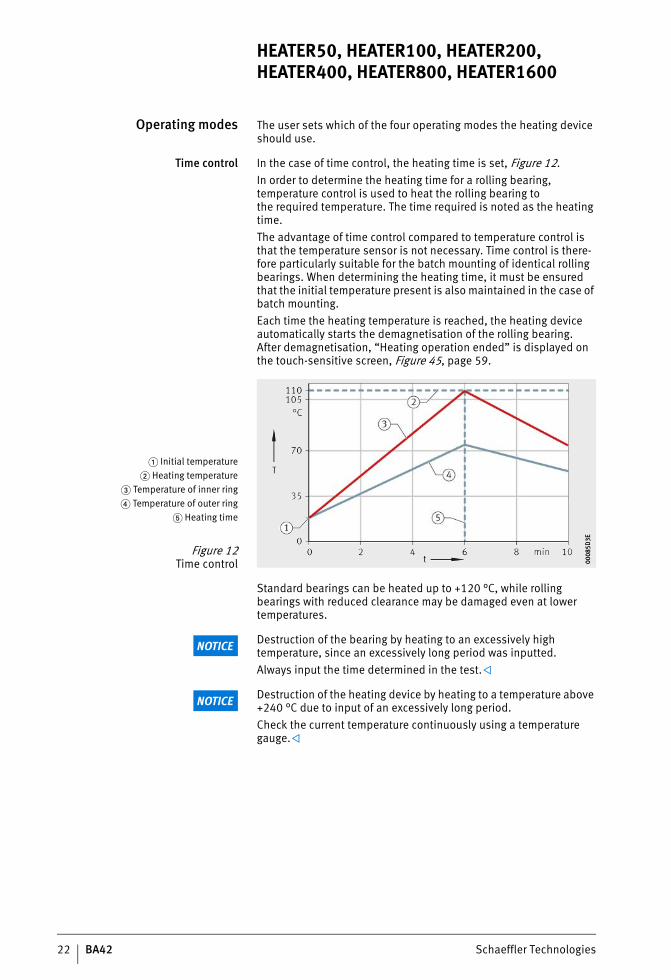
Heating is started using the mechanical key [START/STOP] belowthe touch-sensitive screen.After pressing [START/STOP], the countdown time is counted down, Figure 11.
Once the countdown time has finished, the electromagnetic fieldis generated and the rolling bearing is heated.
� Time control� Temperature control
� Ramp control� Delta-T control
� Set value
Figure 10Heating methods, symbols 00
09E7
4C00
09E7
4C
� [START/STOP]� Display of countdown time
Figure 11Countdown time 00
0A8B
C600
0A8B
C6
ST4_27021615709080203_anleitun.fm Seite 21 Mittwoch, 6. Dezember 2017 9:04 09
22 BA42 Schaeffler Technologies
HEATER50, HEATER100, HEATER200, HEATER400, HEATER800, HEATER1600
Operating modes The user sets which of the four operating modes the heating device should use.
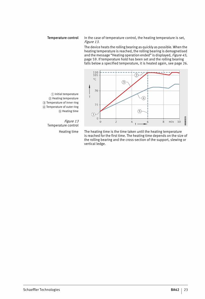
Time control In the case of time control, the heating time is set, Figure 12.In order to determine the heating time for a rolling bearing, temperature control is used to heat the rolling bearing tothe required temperature. The time required is noted as the heating time.The advantage of time control compared to temperature control is that the temperature sensor is not necessary. Time control is there-fore particularly suitable for the batch mounting of identical rolling bearings. When determining the heating time, it must be ensured that the initial temperature present is also maintained in the case of batch mounting.Each time the heating temperature is reached, the heating device automatically starts the demagnetisation of the rolling bearing.After demagnetisation, “Heating operation ended” is displayed on the touch-sensitive screen, Figure 45, page 59.
Standard bearings can be heated up to +120 °C, while rolling bearings with reduced clearance may be damaged even at lower temperatures.
NOTICE Destruction of the bearing by heating to an excessively high temperature, since an excessively long period was inputted.Always input the time determined in the test.
NOTICE Destruction of the heating device by heating to a temperature above +240 °C due to input of an excessively long period.Check the current temperature continuously using a temperature gauge.
� Initial temperature� Heating temperature
� Temperature of inner ring� Temperature of outer ring
� Heating time
Figure 12Time control 00
085D
3E00
085D
3E
ST4_27021615709080203_anleitun.fm Seite 22 Mittwoch, 6. Dezember 2017 9:04 09
Schaeffler Technologies BA42 23
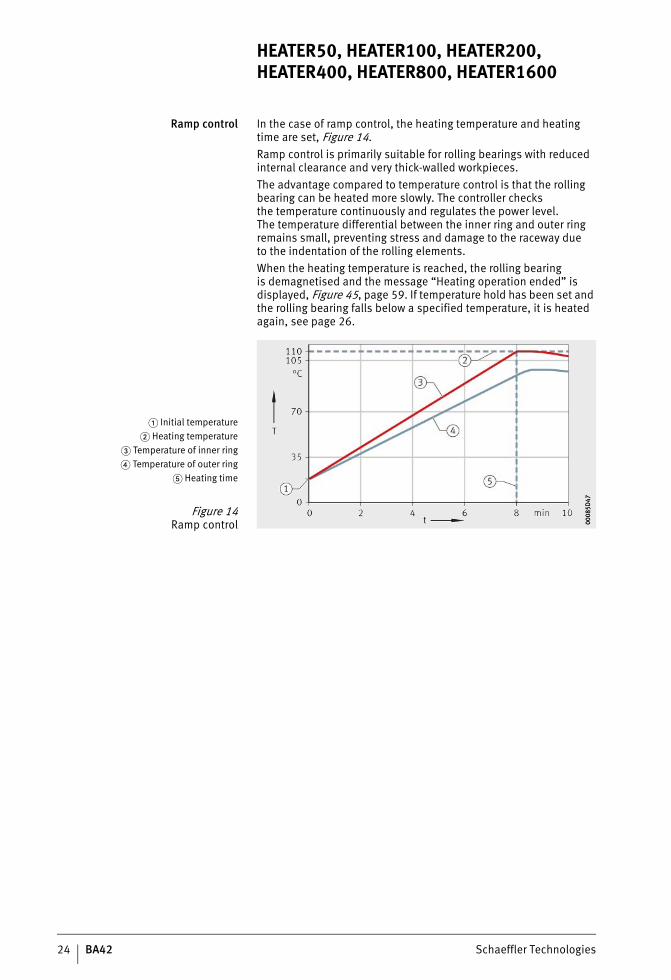
Temperature control In the case of temperature control, the heating temperature is set, Figure 13.The device heats the rolling bearing as quickly as possible. When the heating temperature is reached, the rolling bearing is demagnetised and the message “Heating operation ended” is displayed, Figure 45, page 59. If temperature hold has been set and the rolling bearing falls below a specified temperature, it is heated again, see page 26.
Heating time The heating time is the time taken until the heating temperatureis reached for the first time. The heating time depends on the size of the rolling bearing and the cross-section of the support, slewing or vertical ledge.
� Initial temperature� Heating temperature
� Temperature of inner ring� Temperature of outer ring
� Heating time
Figure 13Temperature control 00
085D
3500
085D
35
ST4_27021615709080203_anleitun.fm Seite 23 Mittwoch, 6. Dezember 2017 9:04 09
24 BA42 Schaeffler Technologies
HEATER50, HEATER100, HEATER200, HEATER400, HEATER800, HEATER1600
Ramp control In the case of ramp control, the heating temperature and heating time are set, Figure 14.Ramp control is primarily suitable for rolling bearings with reduced internal clearance and very thick-walled workpieces.The advantage compared to temperature control is that the rolling bearing can be heated more slowly. The controller checksthe temperature continuously and regulates the power level.The temperature differential between the inner ring and outer ring remains small, preventing stress and damage to the raceway dueto the indentation of the rolling elements.When the heating temperature is reached, the rolling bearingis demagnetised and the message “Heating operation ended” is displayed, Figure 45, page 59. If temperature hold has been set and the rolling bearing falls below a specified temperature, it is heated again, see page 26.
� Initial temperature� Heating temperature
� Temperature of inner ring� Temperature of outer ring
� Heating time
Figure 14Ramp control 00
085D
4700
085D
47
ST4_27021615709080203_anleitun.fm Seite 24 Mittwoch, 6. Dezember 2017 9:04 09
Schaeffler Technologies BA42 25
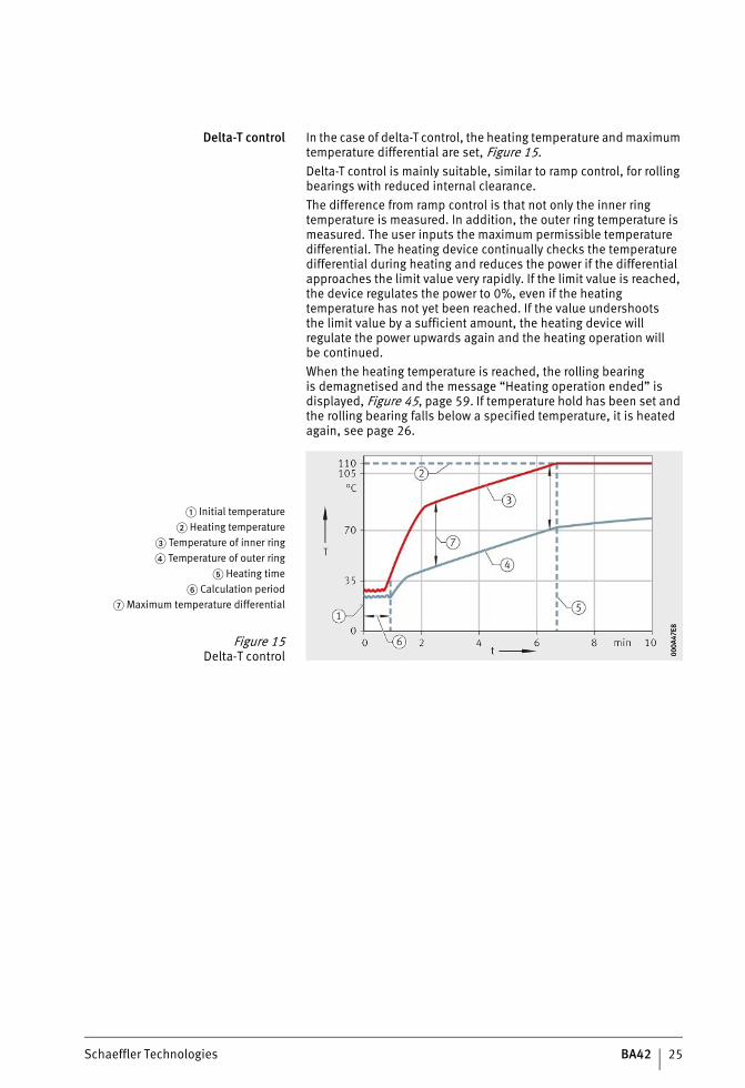
Delta-T control In the case of delta-T control, the heating temperature and maximum temperature differential are set, Figure 15.Delta-T control is mainly suitable, similar to ramp control, for rolling bearings with reduced internal clearance.The difference from ramp control is that not only the inner ring temperature is measured. In addition, the outer ring temperature is measured. The user inputs the maximum permissible temperature differential. The heating device continually checks the temperature differential during heating and reduces the power if the differential approaches the limit value very rapidly. If the limit value is reached, the device regulates the power to 0%, even if the heating temperature has not yet been reached. If the value undershootsthe limit value by a sufficient amount, the heating device will regulate the power upwards again and the heating operation willbe continued.When the heating temperature is reached, the rolling bearingis demagnetised and the message “Heating operation ended” is displayed, Figure 45, page 59. If temperature hold has been set and the rolling bearing falls below a specified temperature, it is heated again, see page 26.
� Initial temperature� Heating temperature
� Temperature of inner ring� Temperature of outer ring
� Heating time� Calculation period
� Maximum temperature differential
Figure 15Delta-T control 00
0A47
E800
0A47
E8
ST4_27021615709080203_anleitun.fm Seite 25 Mittwoch, 6. Dezember 2017 9:04 09
26 BA42 Schaeffler Technologies
HEATER50, HEATER100, HEATER200, HEATER400, HEATER800, HEATER1600
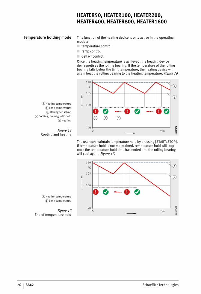
Temperature holding mode This function of the heating device is only active in the operating modes:■ temperature control■ ramp control■ delta-T control.Once the heating temperature is achieved, the heating device demagnetises the rolling bearing. If the temperature of the rolling bearing falls below the limit temperature, the heating device will again heat the rolling bearing to the heating temperature, Figure 16.
The user can maintain temperature hold by pressing [START/STOP]. If temperature hold is not maintained, temperature hold will stop once the temperature hold time has ended and the rolling bearing will cool again, Figure 17.
� Heating temperature� Limit temperature� Demagnetisation
� Cooling, no magnetic field� Heating
Figure 16Cooling and heating 00
09F4
A200
09F4
A2
� Heating temperature� Limit temperature
Figure 17End of temperature hold 00
09F4
9E00
09F4
9E
ST4_27021615709080203_anleitun.fm Seite 26 Mittwoch, 6. Dezember 2017 9:04 09
Schaeffler Technologies BA42 27
Transport and storage The two smallest heating devices can be carried, while the larger and thus heavier heating devices are transported by means of a crane or pallet truck/fork lift truck. In order to protect a heating device against damage during storage, there are rules relating to permissible ambient conditions, see section Storage, page 10.
Transport The safety regulations for transport must be observed, see page 10. For the transport of heavy heating devices, a device with sufficient load capacity must be used.
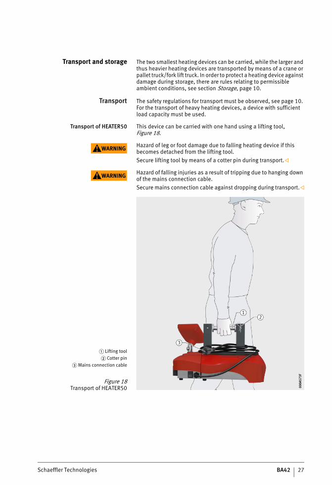
Transport of HEATER50 This device can be carried with one hand using a lifting tool, Figure 18.
WARNING Hazard of leg or foot damage due to falling heating device if this becomes detached from the lifting tool.Secure lifting tool by means of a cotter pin during transport.
WARNING Hazard of falling injuries as a result of tripping due to hanging down of the mains connection cable.Secure mains connection cable against dropping during transport.
� Lifting tool� Cotter pin
� Mains connection cable
Figure 18Transport of HEATER50 00
0A57
3F00
0A57
3F
ST4_27021615709080203_anleitun.fm Seite 27 Mittwoch, 6. Dezember 2017 9:04 09
28 BA42 Schaeffler Technologies
HEATER50, HEATER100, HEATER200, HEATER400, HEATER800, HEATER1600
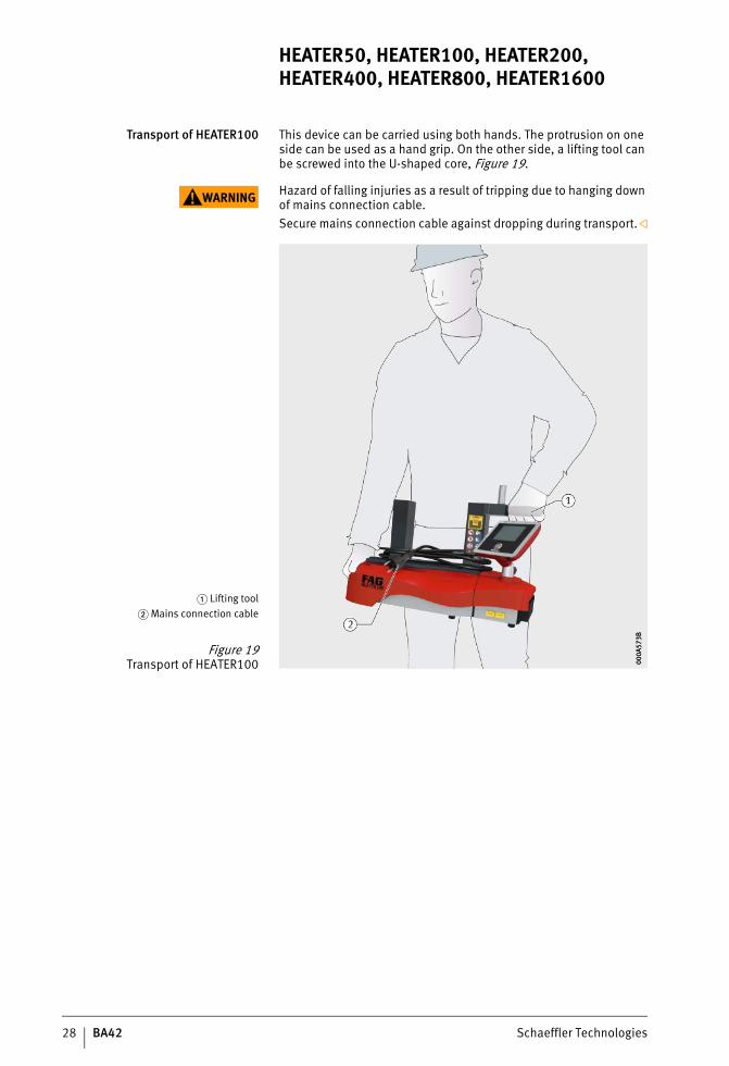
Transport of HEATER100 This device can be carried using both hands. The protrusion on one side can be used as a hand grip. On the other side, a lifting tool can be screwed into the U-shaped core, Figure 19.
WARNING Hazard of falling injuries as a result of tripping due to hanging down of mains connection cable.Secure mains connection cable against dropping during transport.
� Lifting tool� Mains connection cable
Figure 19Transport of HEATER100 00
0A57
3B00
0A57
3B
ST4_27021615709080203_anleitun.fm Seite 28 Mittwoch, 6. Dezember 2017 9:05 09
Schaeffler Technologies BA42 29
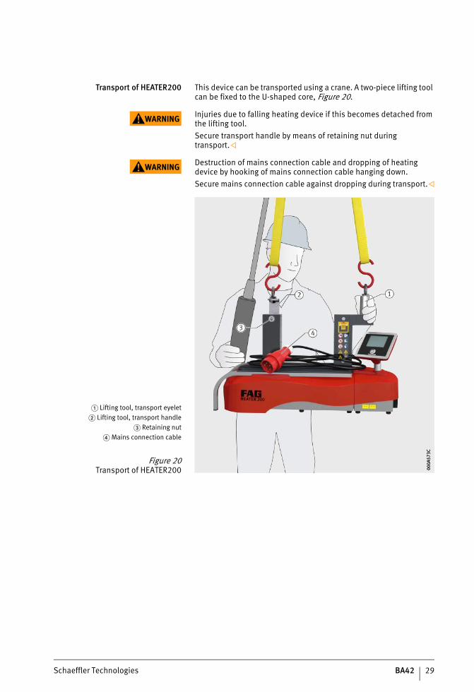
Transport of HEATER200 This device can be transported using a crane. A two-piece lifting tool can be fixed to the U-shaped core, Figure 20.
WARNING Injuries due to falling heating device if this becomes detached from the lifting tool.Secure transport handle by means of retaining nut during transport.
WARNING Destruction of mains connection cable and dropping of heating device by hooking of mains connection cable hanging down.Secure mains connection cable against dropping during transport.
� Lifting tool, transport eyelet� Lifting tool, transport handle
� Retaining nut� Mains connection cable
Figure 20Transport of HEATER200 00
0A57
3C00
0A57
3C
ST4_27021615709080203_anleitun.fm Seite 29 Mittwoch, 6. Dezember 2017 9:05 09
30 BA42 Schaeffler Technologies
HEATER50, HEATER100, HEATER200, HEATER400, HEATER800, HEATER1600
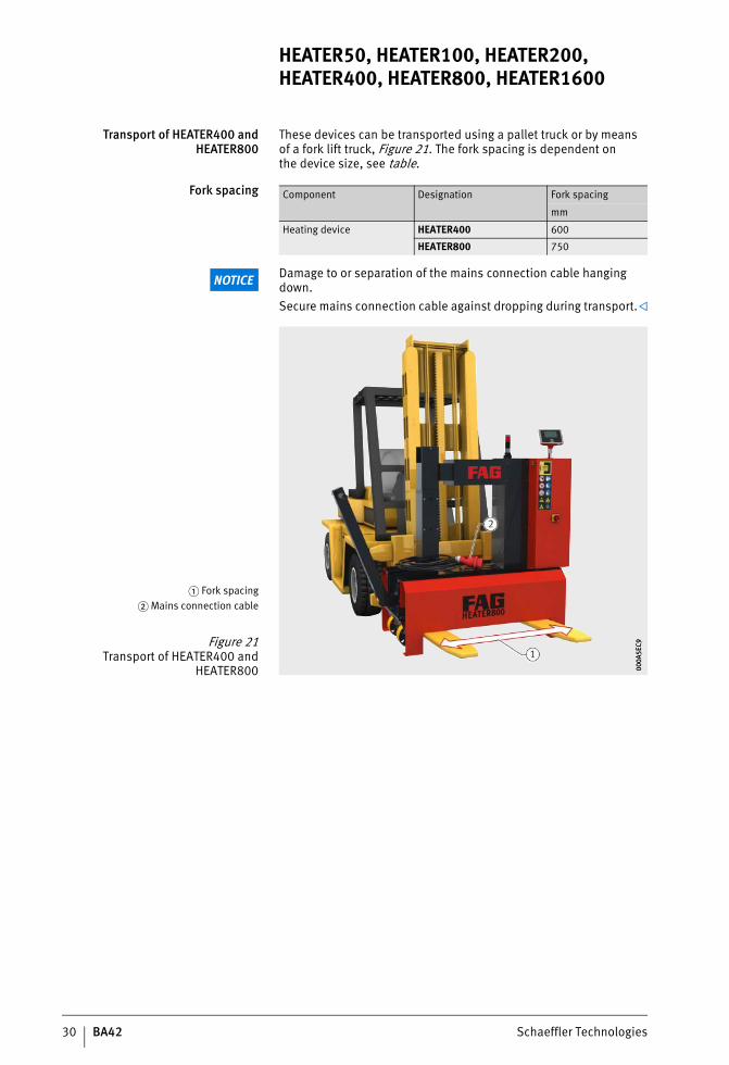
Transport of HEATER400 andHEATER800
These devices can be transported using a pallet truck or by meansof a fork lift truck, Figure 21. The fork spacing is dependent onthe device size, see table.
Fork spacing
NOTICE Damage to or separation of the mains connection cable hanging down.Secure mains connection cable against dropping during transport.
Component Designation Fork spacing
mm
Heating device HEATER400 600
HEATER800 750
� Fork spacing� Mains connection cable
Figure 21Transport of HEATER400 and
HEATER800 000A
5EC9
000A
5EC9
ST4_27021615709080203_anleitun.fm Seite 30 Mittwoch, 6. Dezember 2017 9:05 09
Schaeffler Technologies BA42 31
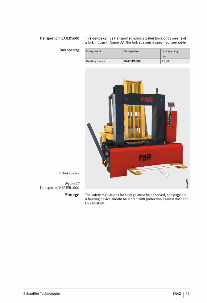
Transport of HEATER1600 This device can be transported using a pallet truck or by means ofa fork lift truck, Figure 22. The fork spacing is specified, see table.
Fork spacing
Storage The safety regulations for storage must be observed, see page 10.A heating device should be stored with protection against dust and UV radiation.
Component Designation Fork spacing
mm
Heating device HEATER1600 1 000
� Fork spacing
Figure 22Transport of HEATER1600 00
0A57
3200
0A57
32
ST4_27021615709080203_anleitun.fm Seite 31 Mittwoch, 6. Dezember 2017 9:05 09
32 BA42 Schaeffler Technologies
HEATER50, HEATER100, HEATER200, HEATER400, HEATER800, HEATER1600
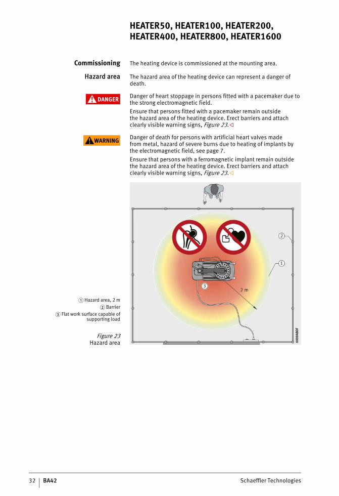
Commissioning The heating device is commissioned at the mounting area.
Hazard area The hazard area of the heating device can represent a danger of death.
DANGER Danger of heart stoppage in persons fitted with a pacemaker due to the strong electromagnetic field.Ensure that persons fitted with a pacemaker remain outsidethe hazard area of the heating device. Erect barriers and attach clearly visible warning signs, Figure 23.
WARNING Danger of death for persons with artificial heart valves madefrom metal, hazard of severe burns due to heating of implants bythe electromagnetic field, see page 7.Ensure that persons with a ferromagnetic implant remain outsidethe hazard area of the heating device. Erect barriers and attach clearly visible warning signs, Figure 23.
� Hazard area, 2 m� Barrier
� Flat work surface capable ofsupporting load
Figure 23Hazard area 00
09AB
DF
0009
ABD
F
ST4_27021615709080203_anleitun.fm Seite 32 Mittwoch, 6. Dezember 2017 9:05 09
Schaeffler Technologies BA42 33
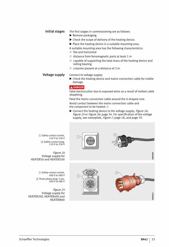
Initial stages The first stages in commissioning are as follows: Remove packaging. Check the scope of delivery of the heating device. Place the heating device in a suitable mounting area.A suitable mounting area has the following characteristics:■ flat and horizontal■ distance from ferromagnetic parts at least 1 m■ capable of supporting the total mass of the heating device and
rolling bearing■ a barrier present at a distance of 2 m.
Voltage supply Connect to voltage supply: Check the heating device and mains connection cable for visible
damage.
DANGERFatal electrocution due to exposed wires as a result of melted cable sheathing.Feed the mains connection cable around the U-shaped core.Avoid contact between the mains connection cable andthe component to be heated. Connect the heating device to the voltage supply, Figure 24;
Figure 25 or Figure 26, page 34. For specification of the voltage supply, see nameplate, Figure 7, page 18, and page 70.
� Safety contact socket,110 V to 230 V
� Safety contact plug,110 V to 230 V
Figure 24Voltage supply for
HEATER50 and HEATER100 000A
4D0F
000A
4D0F
� Safety contact socket,400 V to 480 V
� Three-phase plug, 5 pin,400 V to 480 V
Figure 25Voltage supply for
HEATER200, HEATER400 andHEATER800 00
0A4D
1100
0A4D
11
ST4_27021615709080203_anleitun.fm Seite 33 Mittwoch, 6. Dezember 2017 9:05 09
34 BA42 Schaeffler Technologies
HEATER50, HEATER100, HEATER200, HEATER400, HEATER800, HEATER1600
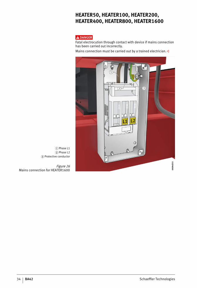
DANGERFatal electrocution through contact with device if mains connection has been carried out incorrectly.Mains connection must be carried out by a trained electrician.
� Phase L1� Phase L2
� Protective conductor
Figure 26Mains connection for HEATER1600 00
0A4D
5500
0A4D
55
ST4_27021615709080203_anleitun.fm Seite 34 Mittwoch, 6. Dezember 2017 9:06 09
Schaeffler Technologies BA42 35
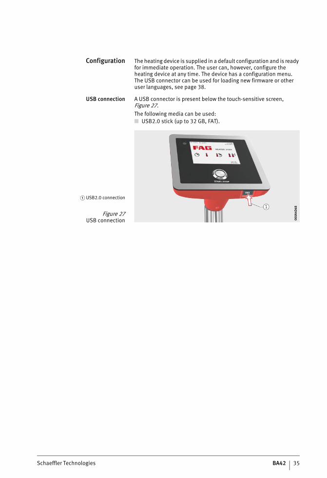
Configuration The heating device is supplied in a default configuration and is ready for immediate operation. The user can, however, configure the heating device at any time. The device has a configuration menu.The USB connector can be used for loading new firmware or other user languages, see page 38.
USB connection A USB connector is present below the touch-sensitive screen, Figure 27.The following media can be used:■ USB2.0 stick (up to 32 GB, FAT).
� USB2.0 connection
Figure 27USB connection 00
0A4D
6800
0A4D
68
ST4_27021615709080203_anleitun.fm Seite 35 Mittwoch, 6. Dezember 2017 9:06 09
36 BA42 Schaeffler Technologies
HEATER50, HEATER100, HEATER200, HEATER400, HEATER800, HEATER1600
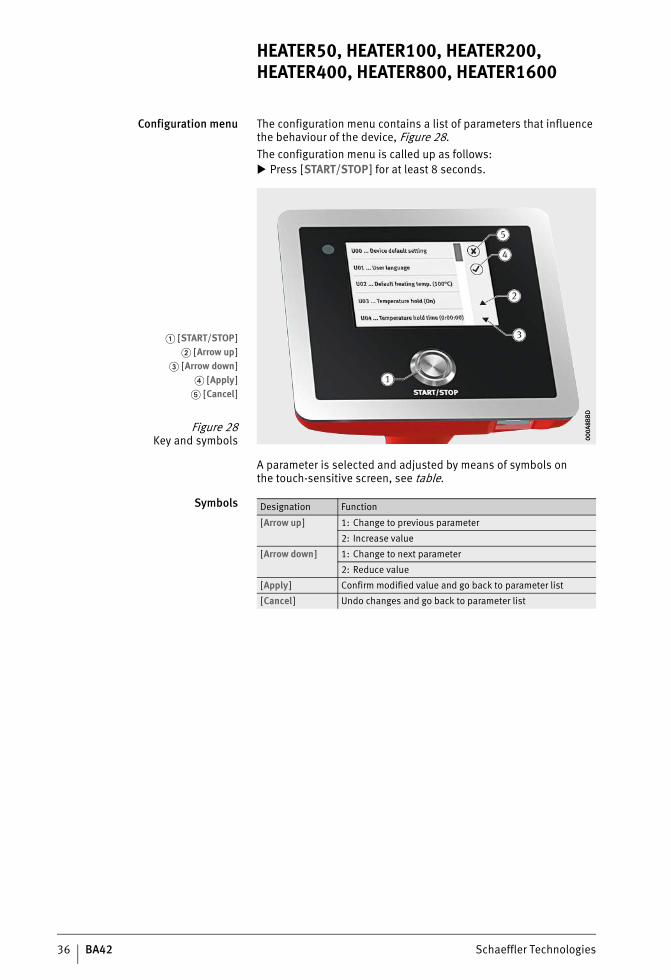
Configuration menu The configuration menu contains a list of parameters that influence the behaviour of the device, Figure 28.The configuration menu is called up as follows: Press [START/STOP] for at least 8 seconds.
A parameter is selected and adjusted by means of symbols onthe touch-sensitive screen, see table.
Symbols
� [START/STOP]� [Arrow up]
� [Arrow down]� [Apply]
� [Cancel]
Figure 28Key and symbols 00
0A8B
BD00
0A8B
BD
Designation Function
[Arrow up] 1: Change to previous parameter
2: Increase value
[Arrow down] 1: Change to next parameter
2: Reduce value
[Apply] Confirm modified value and go back to parameter list
[Cancel] Undo changes and go back to parameter list
ST4_27021615709080203_anleitun.fm Seite 36 Mittwoch, 6. Dezember 2017 9:06 09
Schaeffler Technologies BA42 37
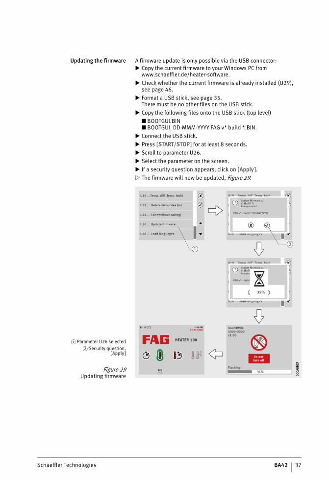
Updating the firmware A firmware update is only possible via the USB connector: Copy the current firmware to your Windows PC from
www.schaeffler.de/heater-software. Check whether the current firmware is already installed (U29),
see page 46. Format a USB stick, see page 35.
There must be no other files on the USB stick. Copy the following files onto the USB stick (top level)
■ BOOTGUI.BIN■ BOOTGUI_DD-MMM-YYYY FAG v* build *.BIN.
Connect the USB stick. Press [START/STOP] for at least 8 seconds. Scroll to parameter U26. Select the parameter on the screen. If a security question appears, click on [Apply ]. The firmware will now be updated, Figure 29.
� Parameter U26 selected� Security question,
[Apply]
Figure 29Updating firmware 00
0A8B
CF00
0A8B
CF
ST4_27021615709080203_anleitun.fm Seite 37 Mittwoch, 6. Dezember 2017 9:06 09
38 BA42 Schaeffler Technologies
HEATER50, HEATER100, HEATER200, HEATER400, HEATER800, HEATER1600
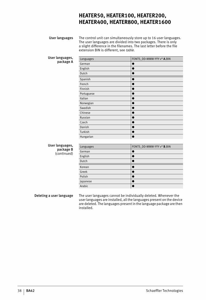
User languages The control unit can simultaneously store up to 16 user languages. The user languages are divided into two packages. There is onlya slight difference in the filenames. The last letter before the file extension BIN is different, see table.
User languages,package A
User languages,package B
(continued)
Deleting a user language The user languages cannot be individually deleted. Whenever the user languages are installed, all the languages present on the device are deleted. The languages present in the language package are then installed.
Languages FONTS_DD-MMM-YYY v* A.BIN
German ●
English ●
Dutch ●
Spanish ●
French ●
Finnish ●
Portuguese ●
Italian ●
Norwegian ●
Swedish ●
Chinese ●
Russian ●
Czech ●
Danish ●
Turkish ●
Hungarian ●
Languages FONTS_DD-MMM-YYY v* B.BIN
German ●
English ●
Dutch ●
Korean ●
Greek ●
Polish ●
Japanese ●
Arabic ●
ST4_27021615709080203_anleitun.fm Seite 38 Mittwoch, 6. Dezember 2017 9:06 09
Schaeffler Technologies BA42 39
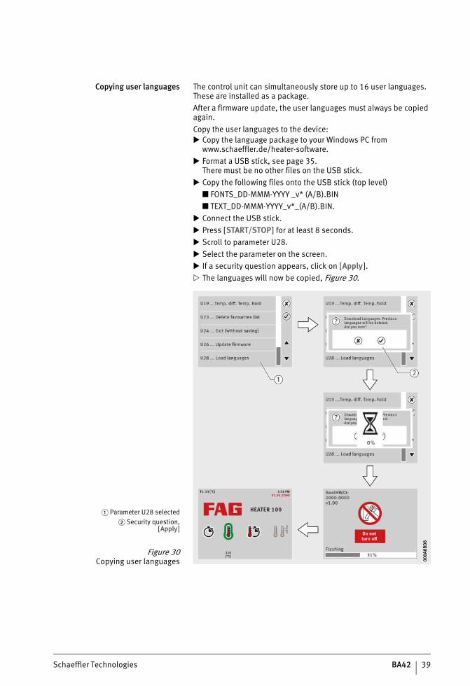
Copying user languages The control unit can simultaneously store up to 16 user languages. These are installed as a package.After a firmware update, the user languages must always be copied again.Copy the user languages to the device: Copy the language package to your Windows PC from
www.schaeffler.de/heater-software. Format a USB stick, see page 35.
There must be no other files on the USB stick. Copy the following files onto the USB stick (top level)
■ FONTS_DD-MMM-YYYY _v* (A/B).BIN■ TEXT_DD-MMM-YYYY_v*_(A/B).BIN.
Connect the USB stick. Press [START/STOP] for at least 8 seconds. Scroll to parameter U28. Select the parameter on the screen. If a security question appears, click on [Apply ]. The languages will now be copied, Figure 30.
� Parameter U28 selected� Security question,
[Apply]
Figure 30Copying user languages 00
0A8B
D8
000A
8BD
8
ST4_27021615709080203_anleitun.fm Seite 39 Mittwoch, 6. Dezember 2017 9:06 09
40 BA42 Schaeffler Technologies
HEATER50, HEATER100, HEATER200, HEATER400, HEATER800, HEATER1600
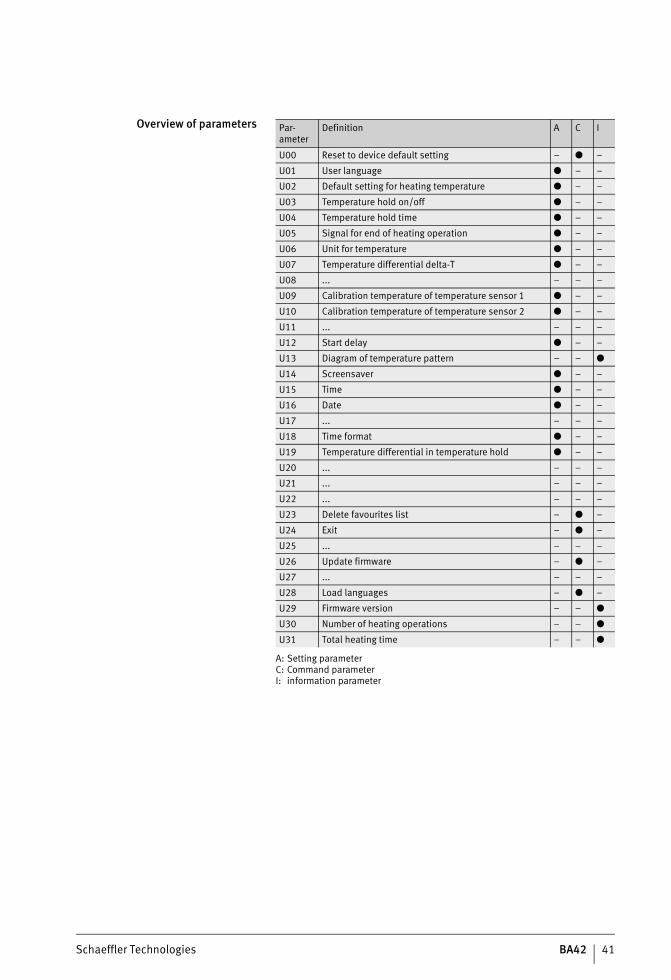
Parameters The behaviour of the device can be set by means of parameters. During configuration, the heating device is set to user mode.There are three different types of parameters, see table, page 41:■ setting parameters■ command parameters■ information parameters.A setting parameter sets and permanently saves a value. In order to change the value set in this way, the parameter must be called up again.With a command parameter, selecting the parameter givesa command that initiates control of the device.An information parameter saves values that can be called up.
ST4_27021615709080203_anleitun.fm Seite 40 Mittwoch, 6. Dezember 2017 9:06 09
Schaeffler Technologies BA42 41
Overview of parameters Par-ameter
Definition A C I
U00 Reset to device default setting – ● –
U01 User language ● – –
U02 Default setting for heating temperature ● – –
U03 Temperature hold on/off ● – –
U04 Temperature hold time ● – –
U05 Signal for end of heating operation ● – –
U06 Unit for temperature ● – –
U07 Temperature differential delta-T ● – –
U08 ... – – –
U09 Calibration temperature of temperature sensor 1 ● – –
U10 Calibration temperature of temperature sensor 2 ● – –
U11 ... – – –
U12 Start delay ● – –
U13 Diagram of temperature pattern – – ●
U14 Screensaver ● – –
U15 Time ● – –
U16 Date ● – –
U17 ... – – –
U18 Time format ● – –
U19 Temperature differential in temperature hold ● – –
U20 ... – – –
U21 ... – – –
U22 ... – – –
U23 Delete favourites list – ● –
U24 Exit – ● –
U25 ... – – –
U26 Update firmware – ● –
U27 ... – – –
U28 Load languages – ● –
U29 Firmware version – – ●
U30 Number of heating operations – – ●
U31 Total heating time – – ●
A: Setting parameterC: Command parameterI: information parameter
ST4_27021615709080203_anleitun.fm Seite 41 Mittwoch, 6. Dezember 2017 9:06 09
42 BA42 Schaeffler Technologies
HEATER50, HEATER100, HEATER200, HEATER400, HEATER800, HEATER1600
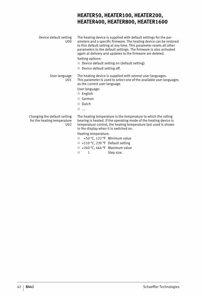
Device default settingU00
The heating device is supplied with default settings for the par-ameters and a specific firmware. The heating device can be restored to this default setting at any time. This parameter resets all other parameters to the default settings. The firmware is also activated again at delivery and updates to the firmware are deleted.Setting options:■ Device default setting on (default setting)■ Device default setting off.
User languageU01
The heating device is supplied with several user languages.This parameter is used to select one of the available user languages as the current user language.User language:■ English■ German■ Dutch■ ...
Changing the default settingfor the heating temperature
U02
The heating temperature is the temperature to which the rolling bearing is heated. If the operating mode of the heating device is temperature control, the heating temperature last used is shownin the display when it is switched on.Heating temperature:■ +50 °C, 122 °F Minimum value■ +110 °C, 230 °F Default setting■ +240 °C, 464 °F Maximum value■ 1 Step size.
ST4_27021615709080203_anleitun.fm Seite 42 Mittwoch, 6. Dezember 2017 9:06 09
Schaeffler Technologies BA42 43
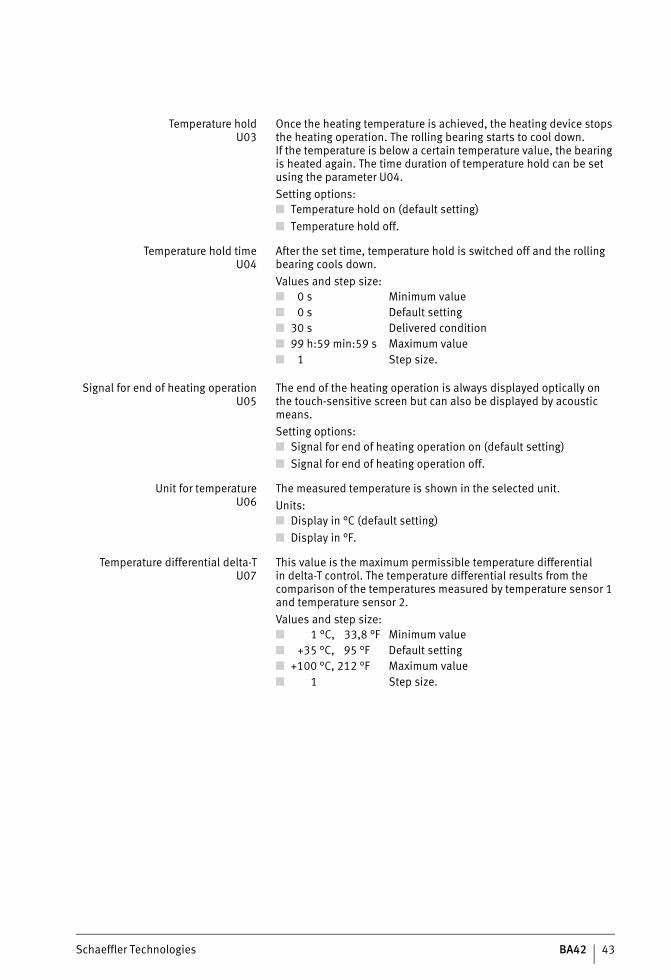
Temperature holdU03
Once the heating temperature is achieved, the heating device stops the heating operation. The rolling bearing starts to cool down.If the temperature is below a certain temperature value, the bearing is heated again. The time duration of temperature hold can be set using the parameter U04.Setting options:■ Temperature hold on (default setting)■ Temperature hold off.
Temperature hold timeU04
After the set time, temperature hold is switched off and the rolling bearing cools down.Values and step size:
Signal for end of heating operationU05
The end of the heating operation is always displayed optically onthe touch-sensitive screen but can also be displayed by acoustic means.Setting options:■ Signal for end of heating operation on (default setting)■ Signal for end of heating operation off.
Unit for temperatureU06
The measured temperature is shown in the selected unit.Units:■ Display in °C (default setting)■ Display in °F.
Temperature differential delta-TU07
This value is the maximum permissible temperature differentialin delta-T control. The temperature differential results from the comparison of the temperatures measured by temperature sensor 1 and temperature sensor 2.Values and step size:
■ 0 s Minimum value■ 0 s Default setting■ 30 s Delivered condition■ 99 h:59 min:59 s Maximum value■ 1 Step size.
■ 1 °C, 33,8 °F Minimum value■ +35 °C, 95 °F Default setting■ +100 °C, 212 °F Maximum value■ 1 Step size.
ST4_27021615709080203_anleitun.fm Seite 43 Mittwoch, 6. Dezember 2017 9:07 09
44 BA42 Schaeffler Technologies
HEATER50, HEATER100, HEATER200, HEATER400, HEATER800, HEATER1600
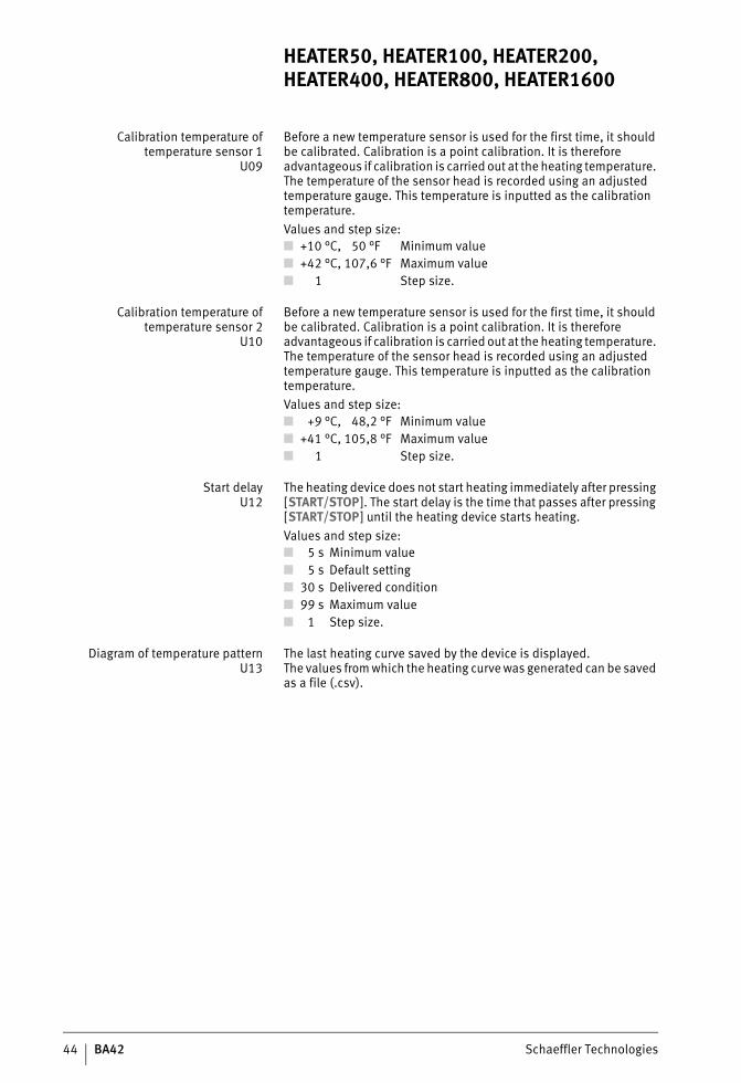
Calibration temperature oftemperature sensor 1
U09
Before a new temperature sensor is used for the first time, it should be calibrated. Calibration is a point calibration. It is therefore advantageous if calibration is carried out at the heating temperature. The temperature of the sensor head is recorded using an adjusted temperature gauge. This temperature is inputted as the calibration temperature.Values and step size:
Calibration temperature oftemperature sensor 2
U10
Before a new temperature sensor is used for the first time, it should be calibrated. Calibration is a point calibration. It is therefore advantageous if calibration is carried out at the heating temperature. The temperature of the sensor head is recorded using an adjusted temperature gauge. This temperature is inputted as the calibration temperature.Values and step size:
Start delayU12
The heating device does not start heating immediately after pressing [START/STOP]. The start delay is the time that passes after pressing [START/STOP] until the heating device starts heating.Values and step size:
Diagram of temperature patternU13
The last heating curve saved by the device is displayed.The values from which the heating curve was generated can be saved as a file (.csv).
■ +10 °C, 50 °F Minimum value■ +42 °C, 107,6 °F Maximum value■ 1 Step size.
■ +9 °C, 48,2 °F Minimum value■ +41 °C, 105,8 °F Maximum value■ 1 Step size.
■ 5 s Minimum value■ 5 s Default setting■ 30 s Delivered condition■ 99 s Maximum value■ 1 Step size.
ST4_27021615709080203_anleitun.fm Seite 44 Mittwoch, 6. Dezember 2017 9:07 09
Schaeffler Technologies BA42 45
ScreensaverU14
The screensaver for the touch-sensitive screen can be switched offby inputting the minimum value.Values and step size:
TimeU15
The time is given in hours (h) and minutes (min).Values and step size:
DateU16
The date is displayed in accordance with DIN 5008 in the format (day.month.year).Delivered condition and step size:
Time formatU18
Display of the time can be selected as one of two formats.Formats:
Temperature differentialin temperature hold
U19
If temperature hold is switched on, the device will carry out heating again if the temperature decreases by this value.
Delete favourites listU23
All favourites can be deleted using this command parameter.Setting options:■ Delete favourites list (default setting)■ Do not delete favourites list.
■ 0 min Minimum value■ 10 min Default setting■ 10 min Delivered condition■ 240 min Maximum value■ 1 Step size.
■ 00 h:00 min Default setting■ 23 h:59 min Maximum value with 24 h■ 11 h:59 min Maximum value with 12 h AM/PM■ 1 Step size.
■ 01.01.2000 Delivered condition■ 1 Step size.
■ 24 h Default setting■ 12 h AM/PM US format.
ST4_27021615709080203_anleitun.fm Seite 45 Mittwoch, 6. Dezember 2017 9:07 09
46 BA42 Schaeffler Technologies
HEATER50, HEATER100, HEATER200, HEATER400, HEATER800, HEATER1600
ExitU24
The configuration menu is exited and the changes to parameters are not saved.Setting options:■ Exit (default setting)■ Do not exit.
Updating firmwareU26
This command parameter starts an update of the firmware.The system checks whether the firmware on the USB stick is more up to data than the existing firmware.Setting options:■ Update (default setting)■ Do not update.
Note This parameter only appears in the list of parameters if a USB stick is inserted.
Loading languagesU28
This command parameter starts loading of a language package.All the existing languages are deleted and the user languages inthe language package are installed. There are two different standard language packages. An individual language package can be created; please contact Customer Service in this case.Setting options:■ Load languages (default setting)■ Do not load languages.
Note If a language package is loaded, all the existing user languages will be deleted.This parameter only appears in the list of parameters if a USB stick is inserted.
Firmware versionU29
This parameter shows the currently installed version of the firmware. Before installing firmware, it can thus be checked whether the most up to date version of the firmware is already installed.
Number of heating operationsU30
This parameter displays the number of heating operations thathave been performed by this device. This information may be useful in searching for errors.
Total heating timeU31
This parameter displays the time for which the device was in operation during all heating operations. This information may be useful in searching for errors.
ST4_27021615709080203_anleitun.fm Seite 46 Mittwoch, 6. Dezember 2017 9:07 09
Schaeffler Technologies BA42 47
Operation It is recommended that only one rolling bearing should ever be heated at one time.A heating operation comprises the following stages:■ Select the suitable heating device■ Select and if necessary change the ledge■ Position the rolling bearing■ Attach the temperature sensor■ Select the heating method■ Set the values■ Carry out heating■ Remove the temperature sensor■ Remove the rolling bearing■ Save the heating curve (optional).
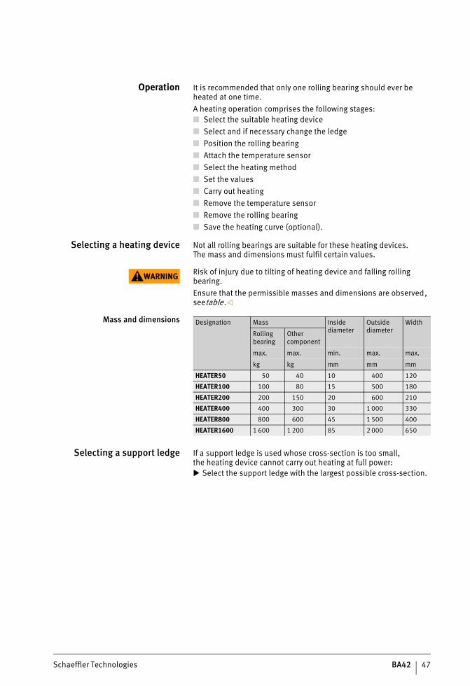
Selecting a heating device Not all rolling bearings are suitable for these heating devices.The mass and dimensions must fulfil certain values.
WARNING Risk of injury due to tilting of heating device and falling rolling bearing.Ensure that the permissible masses and dimensions are observed, seetable.
Mass and dimensions
Selecting a support ledge If a support ledge is used whose cross-section is too small,the heating device cannot carry out heating at full power: Select the support ledge with the largest possible cross-section.
Designation Mass Inside diameter
Outside diameter
Width
Rolling bearing
Other component
max. max. min. max. max.
kg kg mm mm mm
HEATER50 50 40 10 400 120
HEATER100 100 80 15 500 180
HEATER200 200 150 20 600 210
HEATER400 400 300 30 1 000 330
HEATER800 800 600 45 1 500 400
HEATER1600 1 600 1 200 85 2 000 650
ST4_27021615709080203_anleitun.fm Seite 47 Mittwoch, 6. Dezember 2017 9:07 09
48 BA42 Schaeffler Technologies
HEATER50, HEATER100, HEATER200, HEATER400, HEATER800, HEATER1600
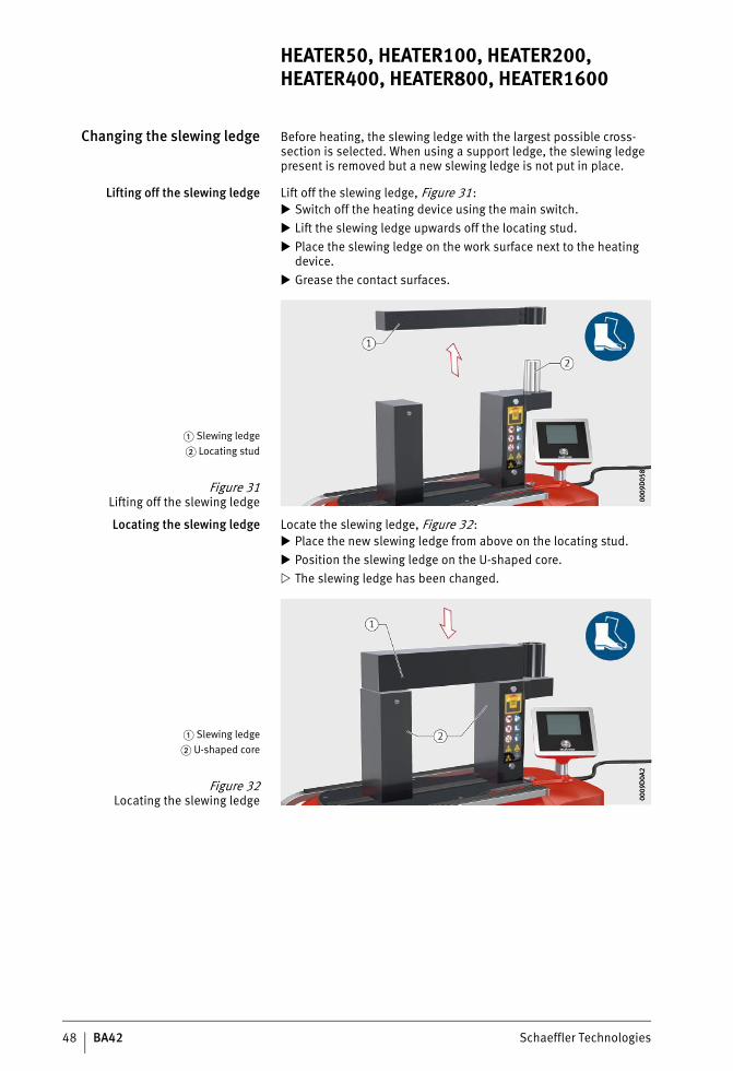
Changing the slewing ledge Before heating, the slewing ledge with the largest possible cross-section is selected. When using a support ledge, the slewing ledge present is removed but a new slewing ledge is not put in place.
Lifting off the slewing ledge Lift off the slewing ledge, Figure 31: Switch off the heating device using the main switch. Lift the slewing ledge upwards off the locating stud. Place the slewing ledge on the work surface next to the heating
device. Grease the contact surfaces.
Locating the slewing ledge Locate the slewing ledge, Figure 32: Place the new slewing ledge from above on the locating stud. Position the slewing ledge on the U-shaped core. The slewing ledge has been changed.
� Slewing ledge� Locating stud
Figure 31Lifting off the slewing ledge 00
09D
058
0009
D05
8
� Slewing ledge� U-shaped core
Figure 32Locating the slewing ledge 00
09D
0A2
0009
D0A
2
ST4_27021615709080203_anleitun.fm Seite 48 Mittwoch, 6. Dezember 2017 9:07 09
Schaeffler Technologies BA42 49
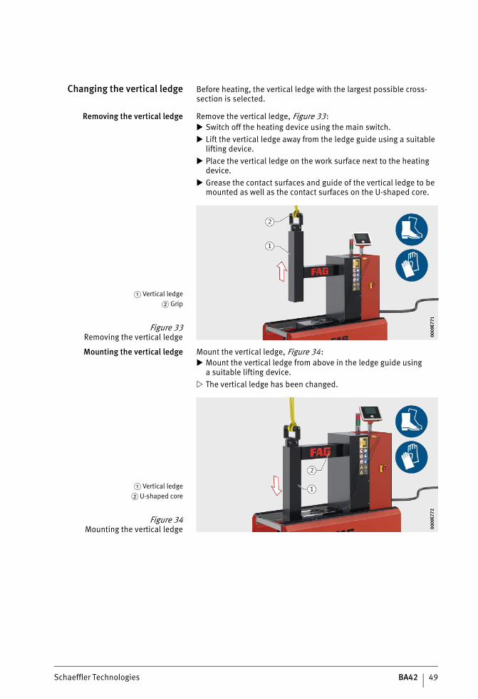
Changing the vertical ledge Before heating, the vertical ledge with the largest possible cross-section is selected.
Removing the vertical ledge Remove the vertical ledge, Figure 33: Switch off the heating device using the main switch. Lift the vertical ledge away from the ledge guide using a suitable
lifting device. Place the vertical ledge on the work surface next to the heating
device. Grease the contact surfaces and guide of the vertical ledge to be
mounted as well as the contact surfaces on the U-shaped core.
Mounting the vertical ledge Mount the vertical ledge, Figure 34: Mount the vertical ledge from above in the ledge guide using
a suitable lifting device. The vertical ledge has been changed.
� Vertical ledge� Grip
Figure 33Removing the vertical ledge 00
09E7
7100
09E7
71
� Vertical ledge� U-shaped core
Figure 34Mounting the vertical ledge 00
09E7
7200
09E7
72
ST4_27021615709080203_anleitun.fm Seite 49 Mittwoch, 6. Dezember 2017 9:07 09
50 BA42 Schaeffler Technologies
HEATER50, HEATER100, HEATER200, HEATER400, HEATER800, HEATER1600
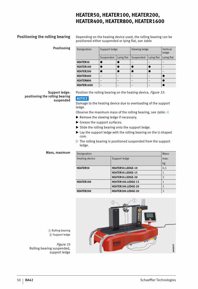
Positioning the rolling bearing Depending on the heating device used, the rolling bearing can be positioned either suspended or lying flat, see table.
Positioning
Support ledge:positioning the rolling bearing
suspended
Position the rolling bearing on the heating device, Figure 35:
NOTICEDamage to the heating device due to overloading of the support ledge.Observe the maximum mass of the rolling bearing, see table. Remove the slewing ledge if necessary. Grease the support surfaces. Slide the rolling bearing onto the support ledge. Lay the support ledge with the rolling bearing on the U-shaped
core. The rolling bearing is positioned suspended from the support
ledge.
Mass, maximum
Designation Support ledge Slewing ledge Vertical ledge
Suspended Lying flat Suspended Lying flat Lying flat
HEATER50 ● ● – – –
HEATER100 ● ● ● ● –
HEATER200 ● ● ● ● –
HEATER400 – – – – ●
HEATER800 – – – – ●
HEATER1600 – – – – ●
Designation Mass
Heating device Support ledge max.
kg
HEATER50 HEATER50.LEDGE-10 0,5
HEATER50.LEDGE-15 1
HEATER50.LEDGE-20 3
HEATER100 HEATER100.LEDGE-15 1
HEATER100.LEDGE-20 3
HEATER200 HEATER200.LEDGE-20 3
� Rolling bearing� Support ledge
Figure 35Rolling bearing suspended,
support ledge 0009
DCF
F00
09D
CFF
ST4_27021615709080203_anleitun.fm Seite 50 Mittwoch, 6. Dezember 2017 9:07 09
Schaeffler Technologies BA42 51
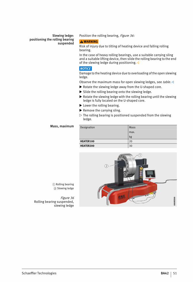
Slewing ledge:positioning the rolling bearing
suspended
Position the rolling bearing, Figure 36:
WARNINGRisk of injury due to tilting of heating device and falling rolling bearing.In the case of heavy rolling bearings, use a suitable carrying sling and a suitable lifting device, then slide the rolling bearing to the end of the slewing ledge during positioning.
NOTICEDamage to the heating device due to overloading of the open slewing ledge.Observe the maximum mass for open slewing ledges, see table. Rotate the slewing ledge away from the U-shaped core. Slide the rolling bearing onto the slewing ledge. Rotate the slewing ledge with the rolling bearing until the slewing
ledge is fully located on the U-shaped core. Lower the rolling bearing. Remove the carrying sling. The rolling bearing is positioned suspended from the slewing
ledge.
Mass, maximum Designation Mass
max.
kg
HEATER100 20
HEATER200 30
� Rolling bearing� Slewing ledge
Figure 36Rolling bearing suspended,
slewing ledge 0009
DD
0000
09D
D00
ST4_27021615709080203_anleitun.fm Seite 51 Mittwoch, 6. Dezember 2017 9:07 09
52 BA42 Schaeffler Technologies
HEATER50, HEATER100, HEATER200, HEATER400, HEATER800, HEATER1600
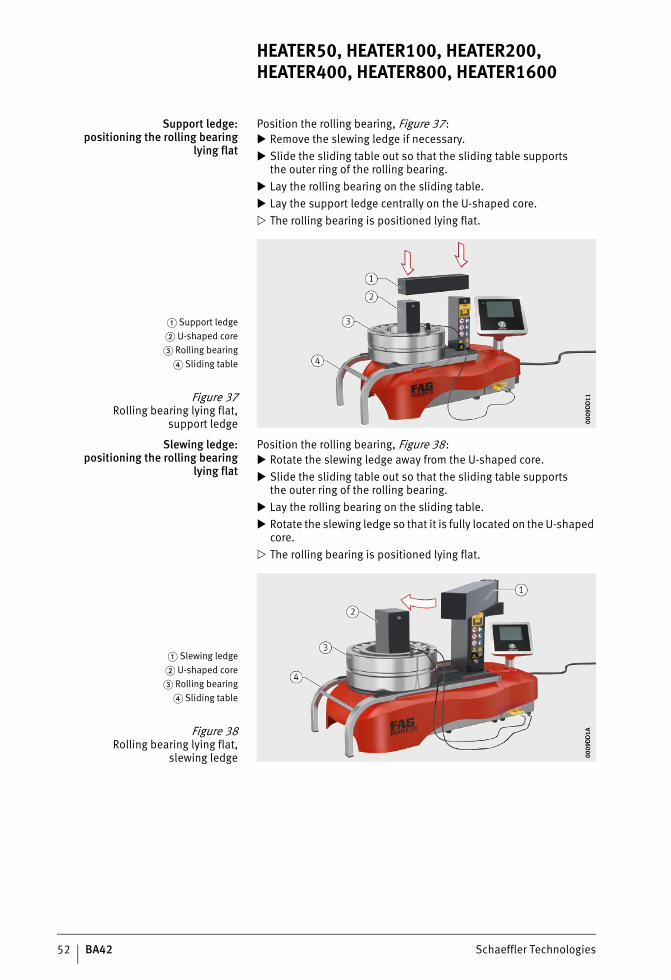
Support ledge:positioning the rolling bearing
lying flat
Position the rolling bearing, Figure 37: Remove the slewing ledge if necessary. Slide the sliding table out so that the sliding table supports
the outer ring of the rolling bearing. Lay the rolling bearing on the sliding table. Lay the support ledge centrally on the U-shaped core. The rolling bearing is positioned lying flat.
Slewing ledge:positioning the rolling bearing
lying flat
Position the rolling bearing, Figure 38: Rotate the slewing ledge away from the U-shaped core. Slide the sliding table out so that the sliding table supports
the outer ring of the rolling bearing. Lay the rolling bearing on the sliding table. Rotate the slewing ledge so that it is fully located on the U-shaped
core. The rolling bearing is positioned lying flat.
� Support ledge� U-shaped core� Rolling bearing
� Sliding table
Figure 37Rolling bearing lying flat,
support ledge 0009
DD
1100
09D
D11
� Slewing ledge� U-shaped core� Rolling bearing
� Sliding table
Figure 38Rolling bearing lying flat,
slewing ledge 0009
DD
1A00
09D
D1A
ST4_27021615709080203_anleitun.fm Seite 52 Mittwoch, 6. Dezember 2017 9:07 09
Schaeffler Technologies BA42 53
Vertical ledge:positioning the rolling bearing
lying flat
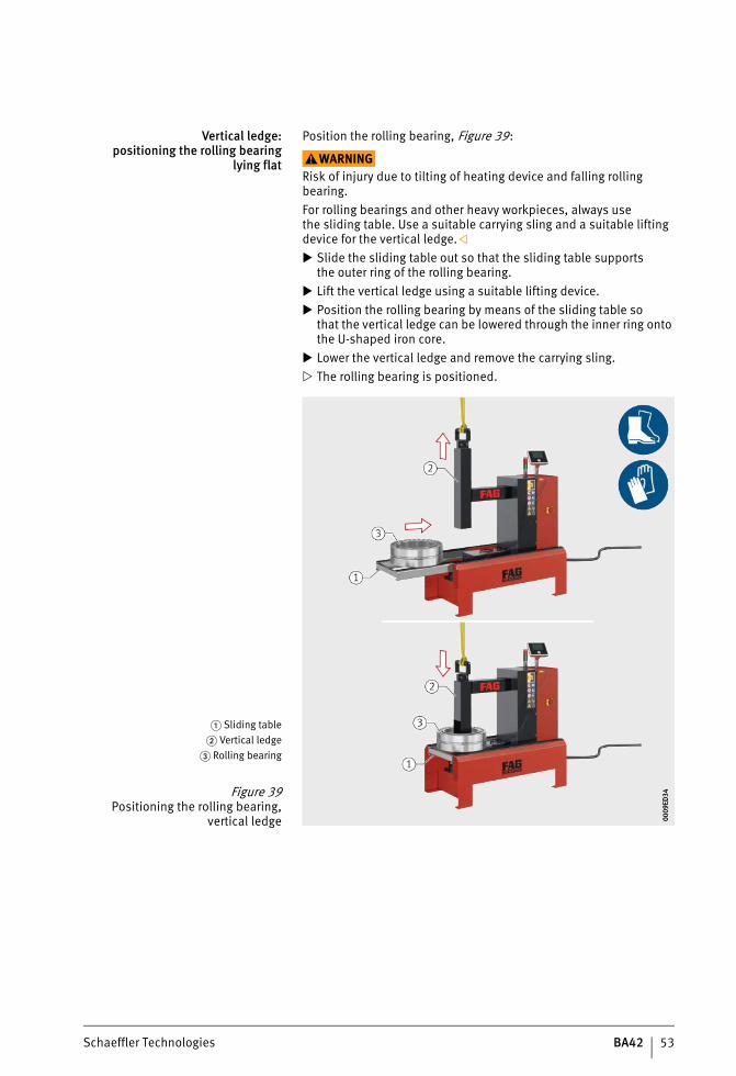
Position the rolling bearing, Figure 39:
WARNINGRisk of injury due to tilting of heating device and falling rolling bearing.For rolling bearings and other heavy workpieces, always usethe sliding table. Use a suitable carrying sling and a suitable lifting device for the vertical ledge. Slide the sliding table out so that the sliding table supports
the outer ring of the rolling bearing. Lift the vertical ledge using a suitable lifting device. Position the rolling bearing by means of the sliding table so
that the vertical ledge can be lowered through the inner ring onto the U-shaped iron core.
Lower the vertical ledge and remove the carrying sling. The rolling bearing is positioned.
� Sliding table� Vertical ledge
� Rolling bearing
Figure 39Positioning the rolling bearing,
vertical ledge 0009
ED34
0009
ED34
ST4_27021615709080203_anleitun.fm Seite 53 Mittwoch, 6. Dezember 2017 9:07 09
54 BA42 Schaeffler Technologies
HEATER50, HEATER100, HEATER200, HEATER400, HEATER800, HEATER1600
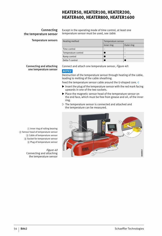
Connectingthe temperature sensor
Except in the operating mode of time control, at least one temperature sensor must be used, see table.
Temperature sensors
Connecting and attachingone temperature sensor
Connect and attach one temperature sensor, Figure 40:
NOTICEDestruction of the temperature sensor through heating of the cable, leading to melting of the cable sheathing.Feed the temperature sensor cable around the U-shaped core. Insert the plug of the temperature sensor with the red mark facing
upwards in one of the two sockets. Place the magnetic sensor head of the temperature sensor on
the end face, which must be free from grease and oil, of the inner ring.
The temperature sensor is connected and attached andthe temperature can be measured.
Heating method Temperature sensor
Inner ring Outer ring
Time control – –
Temperature control ● –
Ramp control ● –
Delta-T control ● ●
� Inner ring of rolling bearing� Sensor head of temperature sensor
� Cable of temperature sensor� Socket for temperature sensor
� Plug of temperature sensor
Figure 40Connecting and attaching
the temperature sensor 0009
DD
3700
09D
D37
ST4_27021615709080203_anleitun.fm Seite 54 Mittwoch, 6. Dezember 2017 9:08 09
Schaeffler Technologies BA42 55
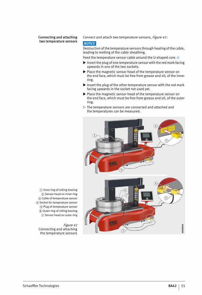
Connecting and attachingtwo temperature sensors
Connect and attach two temperature sensors, Figure 41:
NOTICEDestruction of the temperature sensors through heating of the cable, leading to melting of the cable sheathing.Feed the temperature sensor cable around the U-shaped core. Insert the plug of one temperature sensor with the red mark facing
upwards in one of the two sockets. Place the magnetic sensor head of the temperature sensor on
the end face, which must be free from grease and oil, of the inner ring.
Insert the plug of the other temperature sensor with the red mark facing upwards in the socket not used yet.
Place the magnetic sensor head of the temperature sensor onthe end face, which must be free from grease and oil, of the outer ring.
The temperature sensors are connected and attached andthe temperatures can be measured.
� Inner ring of rolling bearing� Sensor head on inner ring
� Cable of temperature sensor� Socket for temperature sensor
� Plug of temperature sensor� Outer ring of rolling bearing
� Sensor head on outer ring
Figure 41Connecting and attaching
the temperature sensors 0009
DD
4000
09D
D40
ST4_27021615709080203_anleitun.fm Seite 55 Mittwoch, 6. Dezember 2017 9:08 09
56 BA42 Schaeffler Technologies
HEATER50, HEATER100, HEATER200, HEATER400, HEATER800, HEATER1600
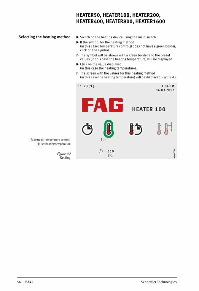
Selecting the heating method Switch on the heating device using the main switch. If the symbol for the heating method
(in this case [Temperature control ]) does not have a green border, click on the symbol.
The symbol will be shown with a green border and the preset values (in this case the heating temperature) will be displayed.
Click on the value displayed(in this case the heating temperature).
The screen with the values for this heating method(in this case the heating temperature) will be displayed, Figure 42.
� Symbol [Temperature control]� Set heating temperature
Figure 42Setting 00
09EE
9000
09EE
90
ST4_27021615709080203_anleitun.fm Seite 56 Mittwoch, 6. Dezember 2017 9:08 09
Schaeffler Technologies BA42 57
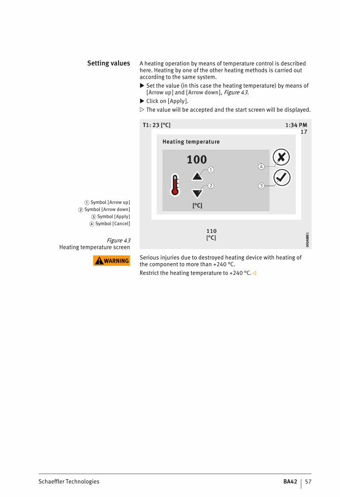
Setting values A heating operation by means of temperature control is described here. Heating by one of the other heating methods is carried out according to the same system. Set the value (in this case the heating temperature) by means of
[Arrow up ] and [Arrow down], Figure 43. Click on [Apply ]. The value will be accepted and the start screen will be displayed.
WARNING Serious injuries due to destroyed heating device with heating ofthe component to more than +240 °C.Restrict the heating temperature to +240 °C.
� Symbol [Arrow up]� Symbol [Arrow down]
� Symbol [Apply]� Symbol [Cancel]
Figure 43Heating temperature screen 00
0A8B
E100
0A8B
E1
ST4_27021615709080203_anleitun.fm Seite 57 Mittwoch, 6. Dezember 2017 9:08 09
58 BA42 Schaeffler Technologies
HEATER50, HEATER100, HEATER200, HEATER400, HEATER800, HEATER1600
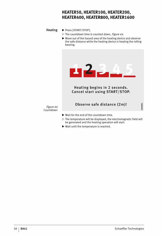
Heating Press [START/STOP]. The countdown time is counted down, Figure 44. Move out of the hazard area of the heating device and observe
the safe distance while the heating device is heating the rolling bearing.
Wait for the end of the countdown time. The temperature will be displayed, the electromagnetic field will
be generated and the heating operation will start. Wait until the temperature is reached.
Figure 44Countdown 00
0A8B
EA00
0A8B
EA
ST4_27021615709080203_anleitun.fm Seite 58 Mittwoch, 6. Dezember 2017 9:08 09
Schaeffler Technologies BA42 59
Cancelling temperature hold If temperature hold is switched on, this can be cancelled before it stops itself.There is normally sufficient time to reach the heating device and activate [START/STOP]. If the countdown time has been set to a low value and the rolling bearing is cooling very quickly, the countdown may start while the user is still in the hazard area.
WARNING Risk of damage to health from remaining in the electromagnetic field.Leave the hazard area of the heating device and observe the safe distance if the countdown time is being counted down.
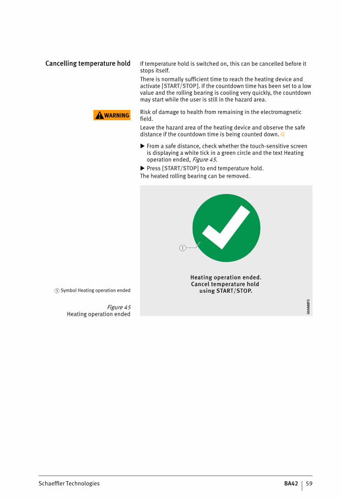
From a safe distance, check whether the touch-sensitive screenis displaying a white tick in a green circle and the text Heating operation ended, Figure 45.
Press [START/STOP] to end temperature hold.The heated rolling bearing can be removed.
� Symbol Heating operation ended
Figure 45Heating operation ended 00
0A8B
F300
0A8B
F3
ST4_27021615709080203_anleitun.fm Seite 59 Mittwoch, 6. Dezember 2017 9:08 09
60 BA42 Schaeffler Technologies
HEATER50, HEATER100, HEATER200, HEATER400, HEATER800, HEATER1600
Removingthe temperature sensor
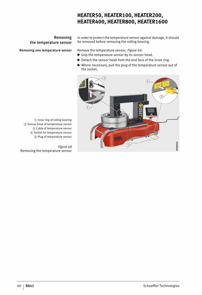
In order to protect the temperature sensor against damage, it should be removed before removing the rolling bearing.
Removing one temperature sensor Remove the temperature sensor, Figure 46: Grip the temperature sensor by its sensor head. Detach the sensor head from the end face of the inner ring. Where necessary, pull the plug of the temperature sensor out of
the socket.
� Inner ring of rolling bearing� Sensor head of temperature sensor
� Cable of temperature sensor� Socket for temperature sensor
� Plug of temperature sensor
Figure 46Removing the temperature sensor 00
09D
D49
0009
DD
49
ST4_27021615709080203_anleitun.fm Seite 60 Mittwoch, 6. Dezember 2017 9:08 09
Schaeffler Technologies BA42 61
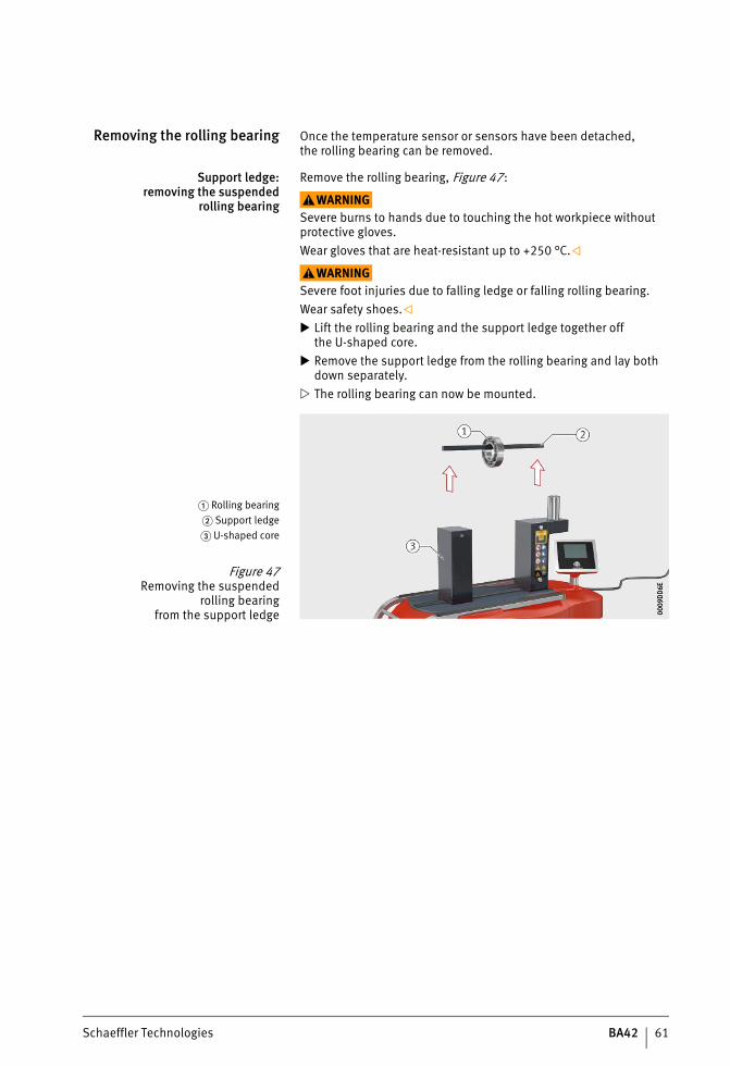
Removing the rolling bearing Once the temperature sensor or sensors have been detached,the rolling bearing can be removed.
Support ledge:removing the suspended
rolling bearing
Remove the rolling bearing, Figure 47:
WARNINGSevere burns to hands due to touching the hot workpiece without protective gloves.Wear gloves that are heat-resistant up to +250 °C.
WARNINGSevere foot injuries due to falling ledge or falling rolling bearing.Wear safety shoes. Lift the rolling bearing and the support ledge together off
the U-shaped core. Remove the support ledge from the rolling bearing and lay both
down separately. The rolling bearing can now be mounted.
� Rolling bearing� Support ledge� U-shaped core
Figure 47Removing the suspended
rolling bearingfrom the support ledge 00
09D
D6E
0009
DD
6E
ST4_27021615709080203_anleitun.fm Seite 61 Mittwoch, 6. Dezember 2017 9:08 09
62 BA42 Schaeffler Technologies
HEATER50, HEATER100, HEATER200, HEATER400, HEATER800, HEATER1600
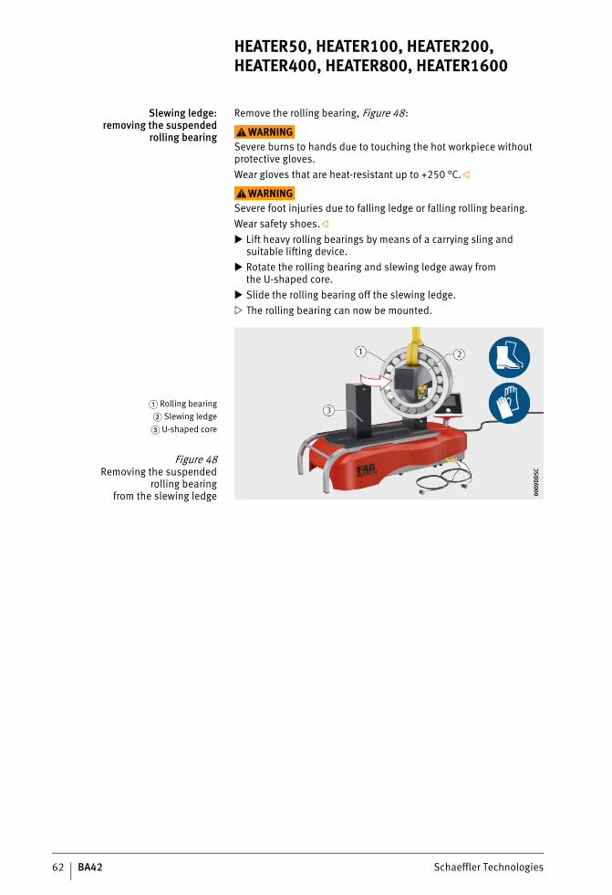
Slewing ledge:removing the suspended
rolling bearing
Remove the rolling bearing, Figure 48:
WARNINGSevere burns to hands due to touching the hot workpiece without protective gloves.Wear gloves that are heat-resistant up to +250 °C.
WARNINGSevere foot injuries due to falling ledge or falling rolling bearing.Wear safety shoes. Lift heavy rolling bearings by means of a carrying sling and
suitable lifting device. Rotate the rolling bearing and slewing ledge away from
the U-shaped core. Slide the rolling bearing off the slewing ledge. The rolling bearing can now be mounted.
� Rolling bearing� Slewing ledge� U-shaped core
Figure 48Removing the suspended
rolling bearingfrom the slewing ledge 00
09D
D5C
0009
DD
5C
ST4_27021615709080203_anleitun.fm Seite 62 Mittwoch, 6. Dezember 2017 9:09 09
Schaeffler Technologies BA42 63
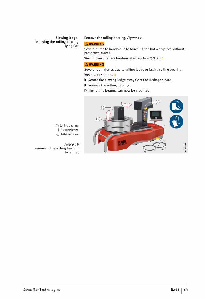
Slewing ledge:removing the rolling bearing
lying flat
Remove the rolling bearing, Figure 49:
WARNINGSevere burns to hands due to touching the hot workpiece without protective gloves.Wear gloves that are heat-resistant up to +250 °C.
WARNINGSevere foot injuries due to falling ledge or falling rolling bearing.Wear safety shoes. Rotate the slewing ledge away from the U-shaped core. Remove the rolling bearing. The rolling bearing can now be mounted.
� Rolling bearing� Slewing ledge� U-shaped core
Figure 49Removing the rolling bearing
lying flat 0009
DD
6500
09D
D65
ST4_27021615709080203_anleitun.fm Seite 63 Mittwoch, 6. Dezember 2017 9:09 09
64 BA42 Schaeffler Technologies
HEATER50, HEATER100, HEATER200, HEATER400, HEATER800, HEATER1600
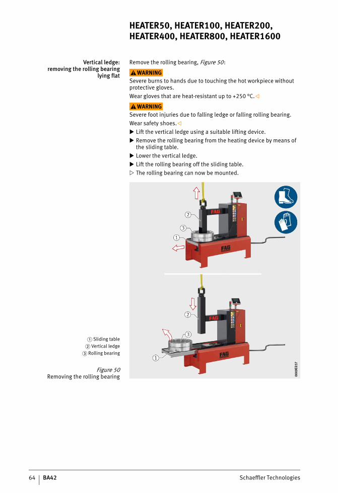
Vertical ledge:removing the rolling bearing
lying flat
Remove the rolling bearing, Figure 50:
WARNINGSevere burns to hands due to touching the hot workpiece without protective gloves.Wear gloves that are heat-resistant up to +250 °C.
WARNINGSevere foot injuries due to falling ledge or falling rolling bearing.Wear safety shoes. Lift the vertical ledge using a suitable lifting device. Remove the rolling bearing from the heating device by means of
the sliding table. Lower the vertical ledge. Lift the rolling bearing off the sliding table. The rolling bearing can now be mounted.
� Sliding table� Vertical ledge
� Rolling bearing
Figure 50Removing the rolling bearing 00
09ED
3700
09ED
37
ST4_27021615709080203_anleitun.fm Seite 64 Mittwoch, 6. Dezember 2017 9:09 09
Schaeffler Technologies BA42 65
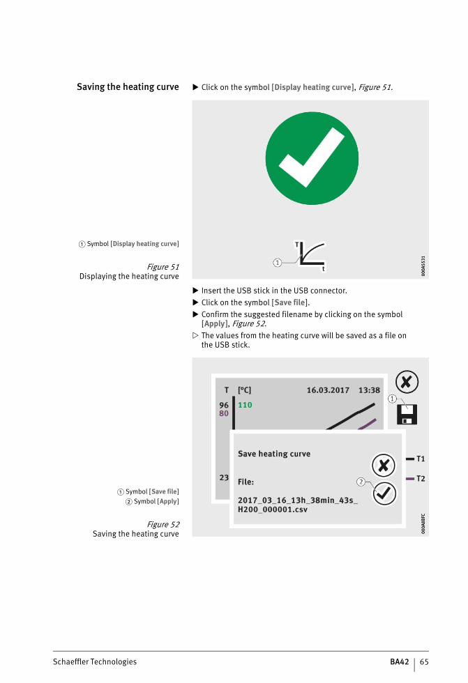
Saving the heating curve Click on the symbol [Display heating curve], Figure 51.
Insert the USB stick in the USB connector. Click on the symbol [Save file]. Confirm the suggested filename by clicking on the symbol
[Apply ], Figure 52. The values from the heating curve will be saved as a file on
the USB stick.
� Symbol [Display heating curve]
Figure 51Displaying the heating curve 00
0A55
3100
0A55
31
� Symbol [Save file]� Symbol [Apply]
Figure 52Saving the heating curve 00
0A8B
FC00
0A8B
FC
ST4_27021615709080203_anleitun.fm Seite 65 Mittwoch, 6. Dezember 2017 9:09 09
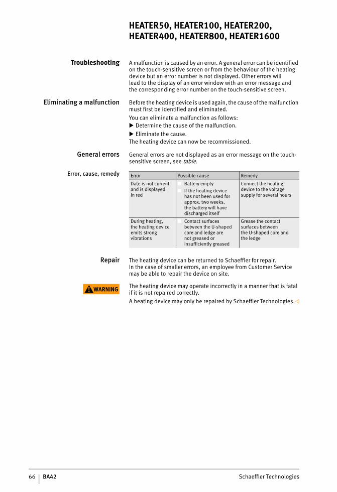
66 BA42 Schaeffler Technologies
HEATER50, HEATER100, HEATER200, HEATER400, HEATER800, HEATER1600
Troubleshooting A malfunction is caused by an error. A general error can be identified on the touch-sensitive screen or from the behaviour of the heating device but an error number is not displayed. Other errors willlead to the display of an error window with an error message andthe corresponding error number on the touch-sensitive screen.
Eliminating a malfunction Before the heating device is used again, the cause of the malfunction must first be identified and eliminated.You can eliminate a malfunction as follows: Determine the cause of the malfunction. Eliminate the cause.The heating device can now be recommissioned.
General errors General errors are not displayed as an error message on the touch-sensitive screen, see table.
Error, cause, remedy
Repair The heating device can be returned to Schaeffler for repair.In the case of smaller errors, an employee from Customer Service may be able to repair the device on site.
WARNING The heating device may operate incorrectly in a manner that is fatal if it is not repaired correctly.A heating device may only be repaired by Schaeffler Technologies.
Error Possible cause Remedy
Date is not current and is displayedin red
■ Battery empty■ If the heating device
has not been used for approx. two weeks,the battery will have discharged itself
Connect the heatingdevice to the voltage supply for several hours
During heating,the heating device emits strong vibrations
■ Contact surfaces between the U-shaped core and ledge arenot greased or insufficiently greased
Grease the contact surfaces betweenthe U-shaped core andthe ledge
ST4_27021615709080203_anleitun.fm Seite 66 Mittwoch, 6. Dezember 2017 9:09 09
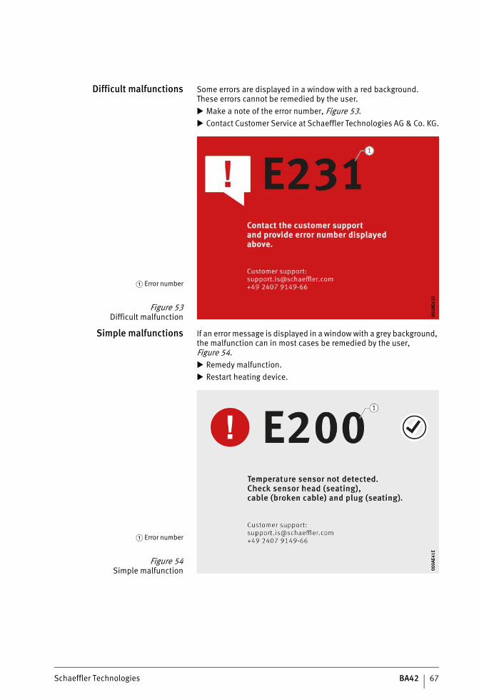
Schaeffler Technologies BA42 67
Difficult malfunctions Some errors are displayed in a window with a red background.These errors cannot be remedied by the user. Make a note of the error number, Figure 53. Contact Customer Service at Schaeffler Technologies AG & Co. KG.
Simple malfunctions If an error message is displayed in a window with a grey background, the malfunction can in most cases be remedied by the user, Figure 54. Remedy malfunction. Restart heating device.
� Error number
Figure 53Difficult malfunction 00
0AE4
3000
0AE4
30
� Error number
Figure 54Simple malfunction 00
0AE4
1E00
0AE4
1E
ST4_27021615709080203_anleitun.fm Seite 67 Mittwoch, 6. Dezember 2017 9:09 09
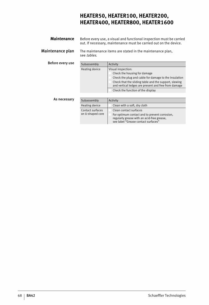
68 BA42 Schaeffler Technologies
HEATER50, HEATER100, HEATER200, HEATER400, HEATER800, HEATER1600
Maintenance Before every use, a visual and functional inspection must be carried out. If necessary, maintenance must be carried out on the device.
Maintenance plan The maintenance items are stated in the maintenance plan,see tables.
Before every use
As necessary
Subassembly Activity
Heating device Visual inspection:■ Check the housing for damage■ Check the plug and cable for damage to the insulation■ Check that the sliding table and the support, slewing
and vertical ledges are present and free from damage
■ Check the function of the display
Subassembly Activity
Heating device ■ Clean with a soft, dry cloth
Contact surfaceson U-shaped core
■ Clean contact surfaces■ For optimum contact and to prevent corrosion,
regularly grease with an acid-free grease,see label “Grease contact surfaces”
ST4_27021615709080203_anleitun.fm Seite 68 Mittwoch, 6. Dezember 2017 9:09 09
Schaeffler Technologies BA42 69
Decommissioning If the heating device will no longer be used regularly, it should be decommissioned.Decommissioning: Switch off the heating device using the main switch. Disconnect the heating device from the voltage supply. Fit the cover to the heating device.
Disposal The device can be returned to Schaeffler for disposal.The heating device can be dismantled in order to dispose ofthe subassemblies separately.The heating device may only be dismantled by an electrician.
WARNING Electrocution due to sudden discharge of capacitors.Before dismantling of the heating device, wait at least 24 h after disconnection from the voltage supply.
WARNING Cutting injuries to the hands when working on sharp-edged components located in the interior of the heating device.In dismantling, use cut-resistant safety gloves.
Regulations Disposal must be carried out in accordance with locally applicable regulations.
ST4_27021615709080203_anleitun.fm Seite 69 Mittwoch, 6. Dezember 2017 9:09 09
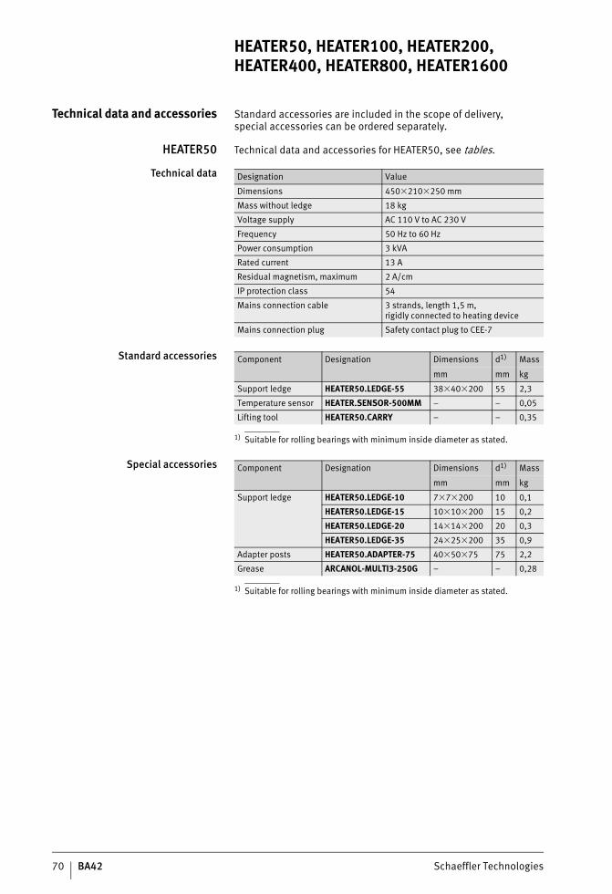
70 BA42 Schaeffler Technologies
HEATER50, HEATER100, HEATER200, HEATER400, HEATER800, HEATER1600
Technical data and accessories Standard accessories are included in the scope of delivery,special accessories can be ordered separately.
HEATER50 Technical data and accessories for HEATER50, see tables.
Technical data
Standard accessories
1) Suitable for rolling bearings with minimum inside diameter as stated.
Special accessories
1) Suitable for rolling bearings with minimum inside diameter as stated.
Designation Value
Dimensions 450�210�250 mm
Mass without ledge 18 kg
Voltage supply AC 110 V to AC 230 V
Frequency 50 Hz to 60 Hz
Power consumption 3 kVA
Rated current 13 A
Residual magnetism, maximum 2 A/cm
IP protection class 54
Mains connection cable 3 strands, length 1,5 m,rigidly connected to heating device
Mains connection plug Safety contact plug to CEE-7
Component Designation Dimensions d1) Mass
mm mm kg
Support ledge HEATER50.LEDGE-55 38�40�200 55 2,3
Temperature sensor HEATER.SENSOR-500MM – – 0,05
Lifting tool HEATER50.CARRY – – 0,35
Component Designation Dimensions d1) Mass
mm mm kg
Support ledge HEATER50.LEDGE-10 7�7�200 10 0,1
HEATER50.LEDGE-15 10�10�200 15 0,2
HEATER50.LEDGE-20 14�14�200 20 0,3
HEATER50.LEDGE-35 24�25�200 35 0,9
Adapter posts HEATER50.ADAPTER-75 40�50�75 75 2,2
Grease ARCANOL-MULTI3-250G – – 0,28
ST4_27021615709080203_anleitun.fm Seite 70 Mittwoch, 6. Dezember 2017 9:09 09
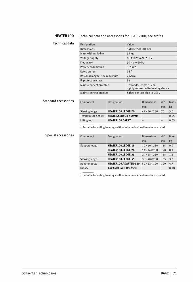
Schaeffler Technologies BA42 71
HEATER100 Technical data and accessories for HEATER100, see tables.
Technical data
Standard accessories
1) Suitable for rolling bearings with minimum inside diameter as stated.
Special accessories
1) Suitable for rolling bearings with minimum inside diameter as stated.
Designation Value
Dimensions 540�275�310 mm
Mass without ledge 35 kg
Voltage supply AC 110 V to AC 230 V
Frequency 50 Hz to 60 Hz
Power consumption 3,7 kVA
Rated current 16 A
Residual magnetism, maximum 2 A/cm
IP protection class 54
Mains connection cable 3 strands, length 1,5 m,rigidly connected to heating device
Mains connection plug Safety contact plug to CEE-7
Component Designation Dimensions d1) Mass
mm mm kg
Slewing ledge HEATER100.LEDGE-70 49�50�280 70 5,6
Temperature sensor HEATER.SENSOR-500MM – – 0,05
Lifting tool HEATER100.CARRY – – 0,05
Component Designation Dimensions d1) Mass
mm mm kg
Support ledge HEATER100.LEDGE-15 10�10�280 15 0,2
HEATER100.LEDGE-20 14�14�280 20 0,4
HEATER100.LEDGE-35 24�25�280 35 1,8
Slewing ledge HEATER100.LEDGE-55 38�40�280 55 3,7
Adapter posts HEATER100.ADAPTER-120 50�62�120 120 4,7
Grease ARCANOL-MULTI3-250G – – 0,28
ST4_27021615709080203_anleitun.fm Seite 71 Mittwoch, 6. Dezember 2017 9:10 09
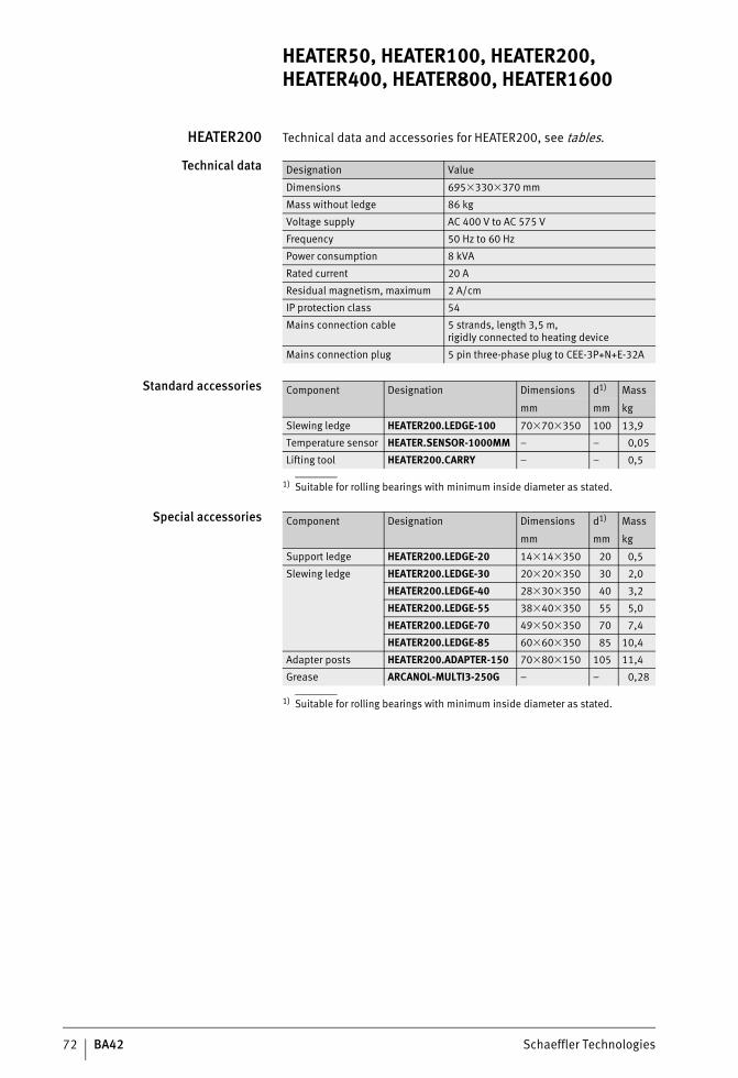
72 BA42 Schaeffler Technologies
HEATER50, HEATER100, HEATER200, HEATER400, HEATER800, HEATER1600
HEATER200 Technical data and accessories for HEATER200, see tables.
Technical data
Standard accessories
1) Suitable for rolling bearings with minimum inside diameter as stated.
Special accessories
1) Suitable for rolling bearings with minimum inside diameter as stated.
Designation Value
Dimensions 695�330�370 mm
Mass without ledge 86 kg
Voltage supply AC 400 V to AC 575 V
Frequency 50 Hz to 60 Hz
Power consumption 8 kVA
Rated current 20 A
Residual magnetism, maximum 2 A/cm
IP protection class 54
Mains connection cable 5 strands, length 3,5 m,rigidly connected to heating device
Mains connection plug 5 pin three-phase plug to CEE-3P+N+E-32A
Component Designation Dimensions d1) Mass
mm mm kg
Slewing ledge HEATER200.LEDGE-100 70�70�350 100 13,9
Temperature sensor HEATER.SENSOR-1000MM – – 0,05
Lifting tool HEATER200.CARRY – – 0,5
Component Designation Dimensions d1) Mass
mm mm kg
Support ledge HEATER200.LEDGE-20 14�14�350 20 0,5
Slewing ledge HEATER200.LEDGE-30 20�20�350 30 2,0
HEATER200.LEDGE-40 28�30�350 40 3,2
HEATER200.LEDGE-55 38�40�350 55 5,0
HEATER200.LEDGE-70 49�50�350 70 7,4
HEATER200.LEDGE-85 60�60�350 85 10,4
Adapter posts HEATER200.ADAPTER-150 70�80�150 105 11,4
Grease ARCANOL-MULTI3-250G – – 0,28
ST4_27021615709080203_anleitun.fm Seite 72 Mittwoch, 6. Dezember 2017 9:10 09
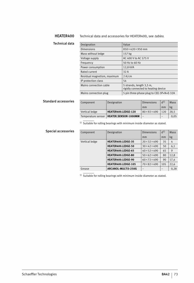
Schaeffler Technologies BA42 73
HEATER400 Technical data and accessories for HEATER400, see tables.
Technical data
Standard accessories
1) Suitable for rolling bearings with minimum inside diameter as stated.
Special accessories
1) Suitable for rolling bearings with minimum inside diameter as stated.
Designation Value
Dimensions 850�420�950 mm
Mass without ledge 157 kg
Voltage supply AC 400 V to AC 575 V
Frequency 50 Hz to 60 Hz
Power consumption 12,8 kVA
Rated current 32 A
Residual magnetism, maximum 2 A/cm
IP protection class 54
Mains connection cable 5 strands, length 3,5 m,rigidly connected to heating device
Mains connection plug 5 pin three-phase plug to CEE-3P+N+E-32A
Component Designation Dimensions d1) Mass
mm mm kg
Vertical ledge HEATER400.LEDGE-120 80�92�490 120 28,5
Temperature sensor HEATER.SENSOR-1000MM – – 0,05
Component Designation Dimensions d1) Mass
mm mm kg
Vertical ledge HEATER400.LEDGE-35 20�32�490 35 4
HEATER400.LEDGE-50 30�42�490 50 6,1
HEATER400.LEDGE-65 40�52�490 65 9
HEATER400.LEDGE-80 50�62�490 80 12,8
HEATER400.LEDGE-90 60�72�490 90 17,4
HEATER400.LEDGE-105 70�82�490 105 22,6
Grease ARCANOL-MULTI3-250G – – 0,28
ST4_27021615709080203_anleitun.fm Seite 73 Mittwoch, 6. Dezember 2017 9:10 09
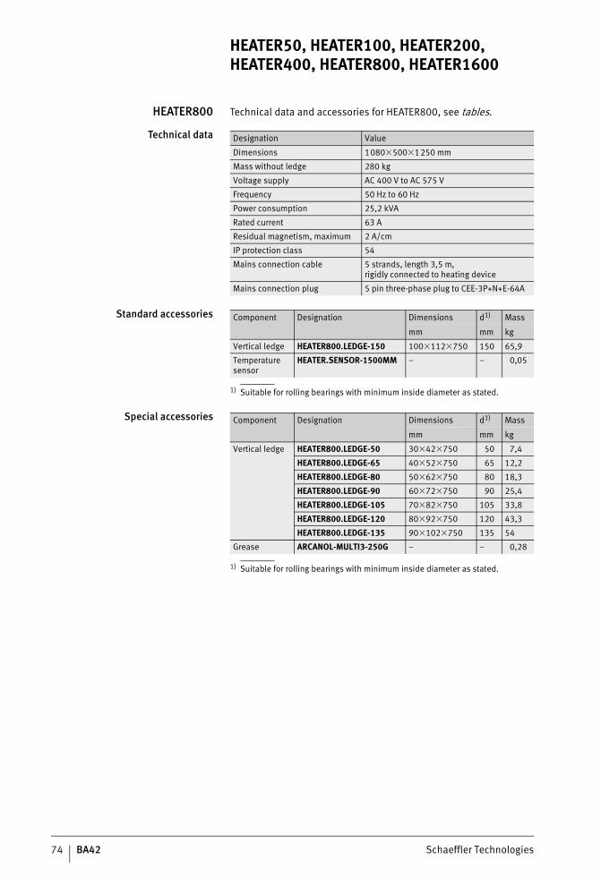
74 BA42 Schaeffler Technologies
HEATER50, HEATER100, HEATER200, HEATER400, HEATER800, HEATER1600
HEATER800 Technical data and accessories for HEATER800, see tables.
Technical data
Standard accessories
1) Suitable for rolling bearings with minimum inside diameter as stated.
Special accessories
1) Suitable for rolling bearings with minimum inside diameter as stated.
Designation Value
Dimensions 1080�500�1250 mm
Mass without ledge 280 kg
Voltage supply AC 400 V to AC 575 V
Frequency 50 Hz to 60 Hz
Power consumption 25,2 kVA
Rated current 63 A
Residual magnetism, maximum 2 A/cm
IP protection class 54
Mains connection cable 5 strands, length 3,5 m,rigidly connected to heating device
Mains connection plug 5 pin three-phase plug to CEE-3P+N+E-64A
Component Designation Dimensions d1) Mass
mm mm kg
Vertical ledge HEATER800.LEDGE-150 100�112�750 150 65,9
Temperature sensor
HEATER.SENSOR-1500MM – – 0,05
Component Designation Dimensions d1) Mass
mm mm kg
Vertical ledge HEATER800.LEDGE-50 30�42�750 50 7,4
HEATER800.LEDGE-65 40�52�750 65 12,2
HEATER800.LEDGE-80 50�62�750 80 18,3
HEATER800.LEDGE-90 60�72�750 90 25,4
HEATER800.LEDGE-105 70�82�750 105 33,8
HEATER800.LEDGE-120 80�92�750 120 43,3
HEATER800.LEDGE-135 90�102�750 135 54
Grease ARCANOL-MULTI3-250G – – 0,28
ST4_27021615709080203_anleitun.fm Seite 74 Mittwoch, 6. Dezember 2017 9:10 09
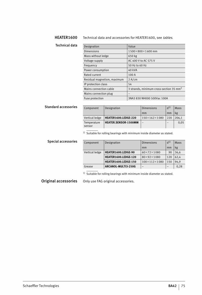
Schaeffler Technologies BA42 75
HEATER1600 Technical data and accessories for HEATER1600, see tables.
Technical data
Standard accessories
1) Suitable for rolling bearings with minimum inside diameter as stated.
Special accessories
1) Suitable for rolling bearings with minimum inside diameter as stated.
Original accessories Only use FAG original accessories.
Designation Value
Dimensions 1500�800�1600 mm
Mass without ledge 650 kg
Voltage supply AC 400 V to AC 575 V
Frequency 50 Hz to 60 Hz
Power consumption 40 kVA
Rated current 100 A
Residual magnetism, maximum 2 A/cm
IP protection class 54
Mains connection cable 3 strands, minimum cross-section 35 mm2
Mains connection plug –
Fuse protection 3NA3 830 NH000 500Vac 100A
Component Designation Dimensions d1) Mass
mm mm kg
Vertical ledge HEATER1600.LEDGE-220 150�162�1080 220 206,1
Temperature sensor
HEATER.SENSOR-1500MM – – 0,05
Component Designation Dimensions d1) Mass
mm mm kg
Vertical ledge HEATER1600.LEDGE-90 60�72�1080 90 36,6
HEATER1600.LEDGE-120 80�92�1080 120 62,4
HEATER1600.LEDGE-150 100�112�1080 150 94,9
Grease ARCANOL-MULTI3-250G – – 0,28
ST4_27021615709080203_anleitun.fm Seite 75 Mittwoch, 6. Dezember 2017 9:10 09
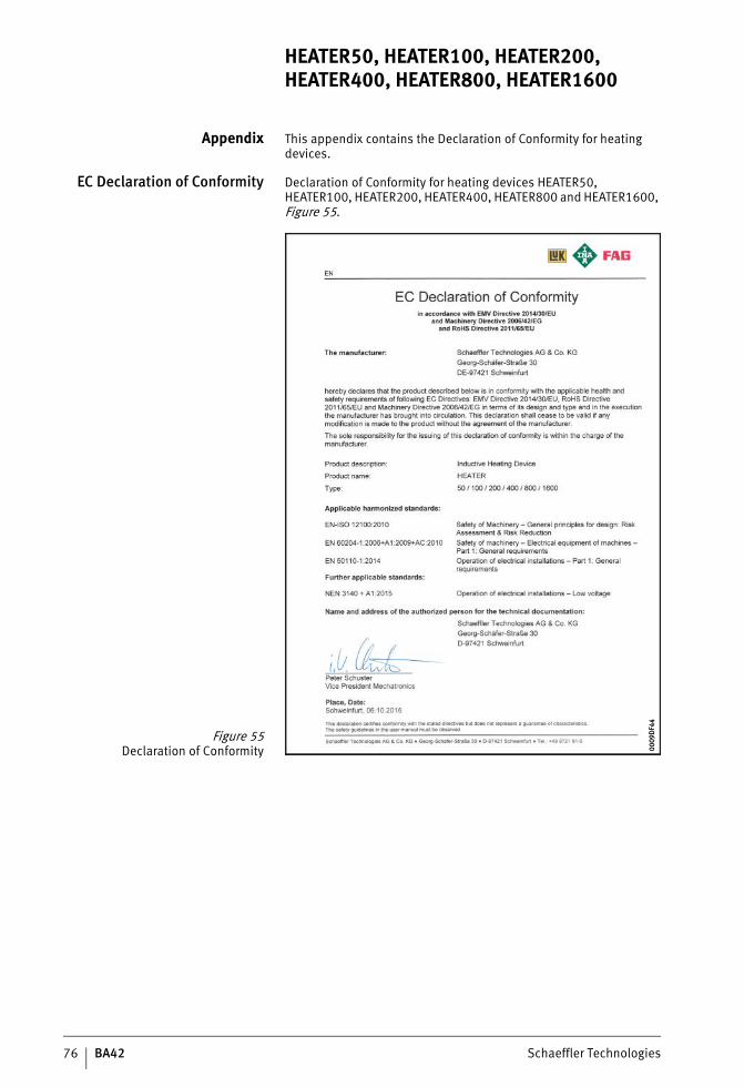
76 BA42 Schaeffler Technologies
HEATER50, HEATER100, HEATER200, HEATER400, HEATER800, HEATER1600
Appendix This appendix contains the Declaration of Conformity for heating devices.
EC Declaration of Conformity Declaration of Conformity for heating devices HEATER50, HEATER100, HEATER200, HEATER400, HEATER800 and HEATER1600, Figure 55.
Figure 55Declaration of Conformity 00
09D
F44
0009
DF4
4
ST4_27021615709080203_anleitun.fm Seite 76 Mittwoch, 6. Dezember 2017 9:10 09


Schaeffler TechnologiesAG & Co. KG
Postfach 126097419 SchweinfurtGermany
Georg-Schäfer-Straße 3097421 SchweinfurtGermany
Phone +49 2407 9149-66Fax +49 2407 9149-59E-mail [email protected] www.schaeffler.com/services
Every care has been taken to ensure the
correctness of the information contained
in this publication but no liability can be
accepted for any errors or omissions.
We reserve the right to make technical
changes.
© Schaeffler Technologies AG & Co. KG
Issued: 2017, december
This publication or parts thereof may not
be reproduced without our permission.
BA 42 GB-DBA 4
2 /
01 /
GB-
D /
201
7121
.5 /
Prin
ted
in G
erm
any
by p
ms