
Indoor Visible Light Communication: A Tutorial and Survey
47
Indoor Visible Light Communication: A Tutorial and Survey Allycan Mapunda, G., Ramogomana, R., Marata, L., Basutli, B., Khan, A. S. & Monamati Chuma, J. Published PDF deposited in Coventry University’s Repository Original citation: Allycan Mapunda, G, Ramogomana, R, Marata, L, Basutli , B, Khan, AS & Monamati Chuma, J 2020, 'Indoor Visible Light Communication: A Tutorial and Survey', Wireless Communications and Mobile Computing, vol. 2020, 8881305. https://dx.doi.org/10.1155/2020/8881305 DOI 10.1155/2020/8881305 ISSN 1530-8669 ESSN 1530-8677 Publisher: Hindawi Copyright © 2020 Galefang Allycan Mapunda et al. This is an open access article distributed under the Creative Commons Attribution License, which permits unrestricted use, distribution, and reproduction in any medium, provided the original work is properly cited.
Transcript of Indoor Visible Light Communication: A Tutorial and Survey

Indoor Visible Light Communication A Tutorial and Survey
Allycan Mapunda G Ramogomana R Marata L Basutli B Khan A S amp Monamati Chuma J
Published PDF deposited in Coventry Universityrsquos Repository
Original citation Allycan Mapunda G Ramogomana R Marata L Basutli B Khan AS amp Monamati Chuma J 2020 Indoor Visible Light Communication A Tutorial and Survey Wireless Communications and Mobile Computing vol 2020 8881305 httpsdxdoiorg10115520208881305
DOI 10115520208881305 ISSN 1530-8669 ESSN 1530-8677
Publisher Hindawi
Copyright copy 2020 Galefang Allycan Mapunda et al This is an open access article distributed under the Creative Commons Attribution License which permits unrestricted use distribution and reproduction in any medium provided the original work is properly cited
Hindawi Wireless Communications and Mobile Computing Volume 2020 Article ID 8881305 46 pages httpsdoiorg10115520208881305
Review Article Indoor Visible Light Communication A Tutorial and Survey
2Galefang Allycan Mapunda 1 Reuben Ramogomana 1 Leatile Marata 1Bokamoso Basutli 1 Amjad Saeed Khan 3 and Joseph Monamati Chuma
1Department of Electrical Computer and Telecommunication Engineering Botswana International University of Science and Technology Private Bag 16 Palapye Botswana 2Center for Wireless Communication University of Oulu Finland 3School of Computing Electronics and Mathematics Coventry University CV1 5FB UK
Correspondence should be addressed to Bokamoso Basutli basutlibbiustacbw
Received 11 March 2020 Revised 8 October 2020 Accepted 10 October 2020 Published 11 December 2020
Academic Editor Daniel G Reina
Copyright copy 2020 Galefang Allycan Mapunda et al This is an open access article distributed under the Creative Commons Attribution License which permits unrestricted use distribution and reproduction in any medium provided the original work is properly cited
With the advancement of solid-state devices for lighting illumination is on the verge of being completely restructured This revolution comes with numerous advantages and viable opportunities that can transform the world of wireless communications for the better Solid-state LEDs are rapidly replacing the contemporary incandescent and fluorescent lamps In addition to their high energy efficiency LEDs are desirable for their low heat generation long lifespan and their capability to switch on and off at an extremely high rate The ability of switching between different levels of luminous intensity at such a rate has enabled the inception of a new communication technology referred to as visible light communication (VLC) With this technology the LED lamps are additionally being used for data transmission This paper provides a tutorial and a survey of VLC in terms of the design development and evaluation techniques as well as current challenges and their envisioned solutions The focus of this paper is mainly directed towards an indoor setup An overview of VLC theory of illumination system receivers system architecture and ongoing developments are provided We further provide some baseline simulation results to give a technical background on the performance of VLC systems Moreover we provide the potential of incorporating VLC techniques in the current and upcoming technologies such as fifth-generation (5G) beyond fifth-generation (B5G) wireless communication trends including sixth-generation (6G) and intelligent reflective surfaces (IRSs) among others
1 Introduction
Optical wireless communication (OWC) over the past decade has acquired a highly substantial interest OWC is perceived as both an alternative and an auspicious interde-pendent communication technique for the conventional radio frequency (RF) technique which has a regulated and licensed electromagnetic spectrum band spanning from 30 kHz to 300GHz Due to an exponential increase in the wireless data traffic and advanced mobile devices there are calamities that are emerging within the RF band This increase leads to spectral crisis such as congestion and maximum data rates that are low relative to OWC Recent developments and standardization of various RF technolo-gies are not able to overcome these looming crisis Numerous
potential RF technologies such as massive multiple-input multiple-output (MIMO) terahertz communication new antenna designs reactive impedance surface (RIS) and non-orthogonal multiple access (NOMA) are still inadequate or under investigation OWC is one candidate technology which has proven to expand wireless technology capabilities
OWC spectral band is between 300 GHz and 30 000 THz (wavelength between 1mm and 10 nm) of the electromag-netic spectrum covering the infrared (IR) visible light and ultraviolet (UV) light bands This being said OWC systems utilize the free-space optical (FSO) links between the trans-mitter and the receiver to transmit data OWC technology has an edge over the RF technology due to various factors These factors include but are not limited to high energy efficiency widely spread bandwidth which is free from
2 Wireless Communications and Mobile Computing
Medium range bull V2V and V2I communication Long range
bull VLC for WLANs bull FSO Short range bull Indoor IR bull Mobile backhaul
bull WBAN amp WPAN bull Underwater communication bull In-fight communication
Ultra-short range Ultra-long range bull Chip communication bull Space communication
Figure 1 Classes of OWC
regulation intrinsic security and low economical costs OWC may be classified into five categories based on the scope of communication links [1ndash3] A representation of these categories is shown in Figure 1
The categories are briefly explained by giving examples of OWC applications In the ultrashort range category (typically about a range of 100 or less) OWC is used for optical com-munication between and within chips of integrated circuits (ICs) For the short-range category (typically within a dis-tance of about 1m) OWC is used to create communication links between the ever-present electronic equipment for daily use The said equipment form the wireless personal area networks (WPANs) Such networks wirelessly interconnect electronic devices that are used around an individualrsquos per-sonal work space Moreover the short range is used for the establishment of wireless body area networks (WBANs) WBAN is a network which continually monitors the health of a patient by means of embedding one or more electronic devices within the body or surface mounting the device at a specific body part The medium-range category (typically up to 10 km) is concerned with but not limited to indoor infrared and communication within the visible light spectrum band which is commonly known as visible light communication (VLC) FSO communication which is also referred to as outdoor intrabuilding links is found as an application of OWC in the long-range category (typically 10) Lastly the ultralong range category (typically 4500 km to 10 000 km) is concerned with laser communication in space for intersatellite links
A number of different research outputs on OWC tech-nology has been presented either for integration with existing technologies or for operating purely on OWC technological competence Tsonev et al [4] presented the development of light-fidelity (Li-Fi) systems to be incorporated in cellular networks using orthogonal frequency division multiplexing (OFDM) Potential uplink schemes that could be utilized for these systems were also discussed The basic aspects of VLC and power line communication (PLC) systems were surveyed by Ma et al [5] The main objective was to find the possibility of integrating PLC and VLC for indoor com-
munication PLC is a technology that paves way for the exist-ing power cables to be utilized for sending data MIMO techniques for the integrated system were also discussed It is possible to directly modulate the LEDs using the data which is being transmitted by the power-line [6] and this makes VLC fit in very well with PLC Demers et al [7] from the networking perspective presented a paper which was fix-ated on FSO Their work pointed out ways in which an implementation of FSO in cellular networks can be executed in order to elevate the capacity of the network
In [8] various issues that exist in wireless RF networking technologies were investigated Studies were done with a per-spective on how these issues may be rectified using VLC sys-tems Furthermore a discussion on applications solutions to the existing VLC challenges and future improvements was presented Heterogeneous systems using both VLC and wireless RF were proposed and implemented by Shao et al [9] One system is a hybrid WiFi-VLC network and the other system is implemented by the parallel aggregation of VLC and WiFi using the Linux operating system bonding tech-nique For the hybrid network a VLC channel which is designed only as a unidirectional channel is used as the downlink To create a complete bidirectional hybrid system the uplink is established by a WiFi back-channel The results of this study demonstrated that the hybrid system performs better than the standard WiFi with regards to throughput and the time taken to load web pages for congested areas One of the promising techniques to address the key chal-lenges in 5G wireless networks known as optical NOMA (O-NOMA) was presented by Marshoud et al [10] A state of the art integration of O-NOMA into VLC networks was overviewed and analyzed in detail Current challenges and anticipated opportunities to allow the designs and integra-tion of O-NOMA into VLC systems were also provided
Zafar et al [11] focused on the dimming techniques that can be designed and realized for VLC systems These tech-niques are anticipated to enable energy-saving and pave way for the provision of illumination control The study pre-sented a motivation behind the need for dimming control mechanisms current challenges driver circuitry current
3 Wireless Communications and Mobile Computing
developments and the envisioned prospects A demonstra-tion of a 3 times 3 imaging MIMO VLC system was presented by Hsu et al [12] The authors extended the bandwidth of the LED transmitter using the preequalization technique With this technique the power of components of high fre-quency such as LEDs can be significantly enhanced while attenuating the low frequency [13] The authors employed the OFDM and bit-loading algorithm [14] for their modula-tion scheme Using the proposed system it was demon-strated that the 1 bandwidth of the phosphor-coated LED is capable of achieving a data rate of 1Gbps over a transmission distance of 1 in free-space In [15] the authors outlined and presented a user-centric design of VLC for heterogeneous networks (HetNets) The authors focused on identifying and elaborating a couple of aspects including service provi-sion system control and signal coverage quality
Authors in [16] outlined a framework that presents the viability of using deep-learning (DL) techniques as compo-nents for the design of optical communication systems The authors designed a multicolored VLC system using RGB LED lamps for the realization of multidimensional color modulation as per the outlined color and illumination speci-fications The aim of the system is to identify a pair of multi-color modulation transmitter and receiver that yields an efficient symbol recovery performance An unsupervised DL technique referred to as autoencoder was used to train the recovery process from the receiver to the transmitter A VLC transmitter-receiver pair and the characterization of the optical channel using the channel layer as well as extra LED intensity control features form part of the recovery pro-cess The transmitter and the receiver are designed together and then optimized The authorrsquos results demonstrated that the designed VLC DL system is better than other proposed techniques with regards to average symbol error probability
11 Related Works Currently there is limited substantial lit-erature survey available on OWC However there have been several papers detailing the state of the art techniques which have been developed over the past years up to the present day Some published articles are aimed at pinpointing and solving the predicaments that are associated with the existing techniques whereas some are focused on designing novel approaches in order to fully acquire the full potential of OWC technologies such as VLC
A thorough and advanced description of VLC is given in one of the most recent surveys [17] The authors provided an overview of VLC technology that entails the physical attri-butes system architecture predominant applications and recent research challenges Besides current research platforms as well as the predicted advancements of the field are detailed A survey of OWC which provides an overview and review of VLC Li-Fi optical camera communication (OCC) and FSO among others is provided in [18] This sur-vey looks into crucial technical knowledge for understanding OWC and presents cutting edge standards for classification of OWC systems system architecture spectrum use and OWC applications The difference between the up-and-coming OWC technologies is also rendered An all-inclusive study of innovative positioning systems technology
based on visible light LED devices was furnished in [19] A well-rooted discussion of the principal components and con-ventions of the said systems as well as an elaborate explana-tion of positioning designs and algorithms is given Existing LED-based indoor positioning systems were explored ana-lyzed and characterized according to their performance with regards to accuracy test environment and cost The study in [19] also presented hybrid indoor positioning systems of VLC and other technologies such as RF and inertial sensor systems The authors in [19] wrapped up their study by pro-viding a classification of outdoor VLC positioning systems They concluded by surveying the primary advances open issues and research outlook of VLC positioning systems
Another survey in [20] presented the incorporation of VLC technologies with WiFi technologies towards fifth-generation (5G) technologies The authors detailed the concepts technologies and challenges of the aforesaid incor-poration A thorough survey for indoor VLC has been provided in [21] with a focus on its novel applications of VLC and diverse practical aspects of the system design These aspects include channel modeling propagation characteris-tics and modulation techniques as well as their capability to provide dimming with minimal flicker to avoid degrada-tion of spectral efficiency
An insight focused on the literature for the development of the VLC physical layer for an indoor setting is given in [22] A related paper discussed the potential of VLC for 5G systems [23] The aspects of outdoor VLC in the form of FSO with the main focus on IR are covered in [1] Diverse elements of FSO for immobile and mobile settings were pre-sented in [24] These elements included the propagation models and directionality within the context of FSO and a discussion on channel modeling multiplexing solid-state lighting (SSL) management noise dimming techniques and drivers The application of VLC for both indoor and out-door settings was surveyed in [25] The authors went on fur-ther to look into the architecture of VLC systems bit error rate (BER) performance measurement light-emitting diode (LED) theory the development of LEDs luminous efficacy and the required power for VLC systems
In this paper we focus on VLC applications which are in the visible light-frequency band of 385789 (from 780 nm to 380 nm) This band falls within the medium range category of OWC as seen in Figure 1 In particular this survey is for the design development and evaluation of VLC with regard to indoor scenery This treatise also delves into the potential of integrating VLC with burgeoning wireless technological trends
12 Paper Structure The remaining part of this article is structured as follows Section 2 gives an overview of VLC in general why it is required together with its applications Sec-tion 3 provides a brief theory of illumination light sources and photometry fundamentals A brief background on photodetectors (PDs) photodetection schemes noise and optical statistics with regard to them being constituents of VLC system receivers is presented in Section 4 Section 5 provides a discussion of VLC system architecture Section 6 presents various elements for the structure of an indoor
4 Wireless Communications and Mobile Computing
VLC system Section 7 gives an overview of the constraints open challenges and the current developments of indoor VLC In Section 8 we investigate the potential of incorporat-ing VLC technology into a number of emergent and future wireless techniques such as 5G IRSs and 6G specifically in sectors where VLC is applicable Finally in Section 9 we conclude the article based on the technical findings of the preceding sections
2 Analysis of VLC
VLC constitutes optical links which enable visible light sources to be employed for transmission of data using air as the transmission medium For indoor application the idea is that the existing illuminating devices are utilized to transmit data using the same energy which is being used for illumination As stated in Section 1 VLC is considered to be a medium-range communication technique This is by virtue of propagation distance which is limited by the lumi-naries which in most cases are white light-emitting diodes (WLEDs)
As of present there is a swift expansion in the lighting and illumination sector The developments in this sector have led to the commissioning of solid-state sources operat-ing within the visible range These sources are gradually phasing out the incandescent sources in many applications and are predicted to become predominant illumination sources [22 26] In addition to general illumination using the solid-state sources a very high data-rate transmission can be achieved The ability of the optical sourcersquos intensity to be modulated at a rapid speed greater than the human eyersquos response paves way for the provision of a data transmis-sion channel
21 Requirement of VLC In RF wireless communication sys-tems the scramble for spectrum is increasing by a very high magnitude yearly [3 21 23 27 28] This problem is mainly driven by an exponential increase in communication devices leading to an increase in data traffic As of Cisco visual net-working index for global mobile data traffic prediction [29] in 2016 global mobile data traffic grew at an estimated rate of 63 from 2015 Progressively in 2017 global mobile data traffic grew at an estimated rate of 71 from 2016 which is 8 greater than that of the previous year From 2017 to 2022 it is predicted that the global mobile data traffic will grow sevenfold to 77 exabytes per month at a compound annual growth rate (CAGR) of 46 over this forecast period [30]
The major contributors to the growth of the global mobile data traffic are fueled by the growth of various kinds of wireless devices worldwide Every year there is an intro-duction of a significant number of devices with diverse form factors improved and increased capabilities and intelligence to the market Global mobile devices and connections grew from 76 billion in 2015 up to 80 billion in 2016 [29] In 2017 global mobile devices grew from 79 billion in 2016 to 86 billion in 2017 [30] In [29] it is predicted that there will be 116 billion mobile devices and connections by 2021 at a CAGR of 8 globally On the other hand a recent forecast
in [30] shows that by 2022 there will be 123 billion mobile devices and connections globally at a CAGR of 75
Despite the constant development and standardization of wireless RF technologies the efforts are falling short in meet-ing the demand for the limited RF band This shortfall leads to a bottleneck which deprives meeting the needs such as high data rates and the required capacity Over several decades the RF band has been exploited to a point that there is very little potential to exploit further However there are various research efforts on RF technological advances that are currently ongoing in order to improve the spectral effi-ciency Such technological advances include but not limited to millimeter-wave (mm-Wave) [31ndash34] massive MIMO [35ndash40] NOMA [41ndash43] and network densification [40] In comparison to OWC there is extreme power consump-tion in RF communication systems despite the innovative countermeasures such as low-power ICs The above compli-cations call for an urgent need for alternate and complemen-tary wireless techniques to be developed and implemented To resolve the RF impediments researchers in the field are shifting their focus to new research areas of wireless communication
One of the solutions that have been proposed with an aim to complement the conventional RF wireless communication systems is to explore other frequency bands in the electro-magnetic spectrum specifically the visible light band This shift has led to the discovery of a potential and favorable wireless communication technique commonly referred to as VLC [4 22 44] This technique is anticipated to reduce a huge amount of traffic on the conventional wireless RF tech-nology which is heavily congested A comparison between VLC and RF technologies can be found in [22]
VLC comes with its own pros and cons just like any other existing innovation Nevertheless the pros overcome the cons and some of the cons have a possibility of being miti-gated The most predominant drawback of VLC is that an increase in the link distance sharply decreases the maximum achievable data rate as VLC is a noncoherent communication technique Relative to RF firstly VLC is based on part of the spectrum band which is regulatory-free from international and local authorities as the visible light spectrum is under the industrial scientific and medical (ISM) band By this virtue VLC offers a wireless communication service with an enormous bandwidth capable of transmitting at very high data rates with no requirement for a license The VLC band-width is approximately ten thousand folds that of the entire RF bandwidth
Secondly the luminaires used for VLC systems are energy efficient as they use less power despite their high light intensity and they also come at a very low cost This makes the VLC systems more economical as they are used for both illumination and data transmission Thirdly the VLC sys-tems are much safer compared to RF systems in the sense that there are minimal or no medical health complications caused by visible light Emissions from RF equipment and devices may be harmful to humans and medical equipment if the radiation power exceeds a particular measure See [45ndash49] for more details on the effects of RF radiation on human beings
5 Wireless Communications and Mobile Computing
In VLC systems there is no requirement for sophisticated antennas to transmit data from the light source through air One more factor that makes VLC systems attractive over RF systems is that they have intrinsic security The control of transmitted data in the physical layer is simple as commu-nication is commonly in line of sight (LoS) This avoids inva-sion of the communication system by passive eavesdroppers Moreover in contrast to RF visible light is not capable of penetrating solid surfaces such as walls The incapability of wall penetration enables the creation of small cells to trans-mit without interference between cell locations (ie intercell interference)
VLC technology is at an early stage with merely a small fraction that has been explored However there are substan-tial research efforts that are currently ongoing leading to rapid developments as needed to set forth the deployment of VLC into vast practical applications
22 Applications of VLC VLC can be applied in many sectors ranging from household level to factory level It is however worth mentioning that with VLC the intention is not to supersede the existing technologies Such technologies include RF mobile networks RF WLANs and PowerLANs Relatively it is explored as an augmentation of these existing technologies [4 5 15 20 21 23 44 50 51] VLC offers an extra data layer at higher rates in diverse network environ-ments This presents a provision for an alternate wireless data link in areas where there is no desire or no possibility or less sufficiency for wireless radio transmission Some of the appli-cations where VLC may be a preference over wireless RF include as follows
221 Community Sectors As a consequence of expansive network traffic in various modern-day institutions such as governmental organizations universities and firms the existing networking technologies are being overwhelmed VLC systems may be used to help reduce the data traffic load from the existing RF and optical fiber technologies This technique will offer higher data rates in such institutions The deployment of VLC will be realized without the need for resource-intensive connections such as that of optic fiber Facilitation of tasks such as monitoring and surveillance will consequently be easy for public safety
222 Healthcare Facilities Radio wave transmission is known to interfere with some health care equipment such as magnetic resonance imaging (MRI) scans and electrocar-diograph (ECG) machines To alleviate this problem of elec-tromagnetic wave interference (EMI) VLC can be utilized to offer data and monitoring services in areas where radio waves are not desirable due to their interference with RF sensitive procedural equipment
223 Aviation Sector Currently there is demand and desire for the provision of flight safe and high-speed data transmis-sion from passengers and aviation service providers during flight Some service providers offer aircraft-to-earth data links whereas some provide WiFi solutions that are compatible with flight equipment These provisions are well-founded and safe However they are not economical
to implement and the baud rate per individual user is exceedingly low [52]
The provision of VLC would be an ideal alternative for the aviation industry to provide outstanding wireless data services that are economical Consequently this will elimi-nate or reduce the effects of RF signals that are well known to interfere with the cockpit communication systems This provision will allow the illuminating WLEDs in flights to provide both reading lights and optical data transmitters with a different approach but with minor similarities as seen in [53] This provision could also be used for broadcasting using the VLC system as the downlink The uplink may be modeled using the infrared link to allow passenger connectivity during the flight [52]
224 Vehicular Communication In modern-day lives vehi-cles have come to be a vital asset to humans In addition to quality and reliable transportation services human beings desire more ad hoc features The most crucial features are in relation to communication and safety These include in-vehicle internet access forward collision warning emergency electronics brake lights blind-spot warning and lane change warning control loss warning intersection movement assist and do not pass warning [22 54]
It is envisioned that by 2025 90 of vehicles being sold will have the capability of communicating with each other and infrastructure [55] With these demands and develop-ments it means that vehicles will generate higher data rates thanks to the number of sensors they are equipped with RF technologies will fall short because of the current impedi-ments There is a requirement for a large bandwidth and low latency for reliable reach-ability High-speed VLC tech-nology can be easily adapted because of the ever-present vehicular lights and traffic light infrastructure
225 Homeland Security Quick and flexible reactions in sit-uations of dismay such as unforeseen natural events terror attacks and emergencies are essential In such situations where some RF communication infrastructures may not be dependable as a consequence of damage or attack VLC may be momentarily deployed to provide secure and rapid data services This will allow for critical tasks such as safe evacuation and counterattack measures to be carried out in a timely manner despite the malfunction of the conventional infrastructure used for data transmission
226 Industrial Factories Under certain conditions and cir-cumstances RF transmission may possibly cause explosions in hazardous areas such as petrochemical plants mines and explosive devices plants [56 57] Thus it is very imper-ative that the installation of wireless RF networks be planned and executed with expertise in order to reduce the potential risk However it is very rare for instances of ignition to occur [56ndash58] RF techniques such as leaky wave antennas have been found to be very useful in spatially constrained environ-ments such as underground mines [59] Nonetheless equip-ment for such technologies require separate deployments In these areas factories may find VLC as the most suited form of wireless communication as it will be embedded in the
6 Wireless Communications and Mobile Computing
Figure 2 Evolution of illumination [62]
already existing illuminating infrastructure providing both illumination and high data rate transmission
VLC technology has already been commercialized by var-ious entities Acuity Brands (formerly known as ByteLight) offer indoor localization based on VLC technology to some retail stores [60] Philips Lighting also has a similar system to that of Acuity brands featuring LEDs and smartphones A system for retail stores developed by Fujitsu which mimics the quick response (QR) code technology features the VLC technology to embed product data for customers to scan the invisible data using their smartphones [61]
3 Light Sources and Illumination
Different types of illumination sources exist These sources evolved from back in the days when illumination was mainly achieved by the utilization of fire and wax candles Illumina-tion evolution is shown in Figure 2 The figure depicts the improvements at each stage of the evolution
Through the years since the moonlight fire and candle era illumination has substantially developed and we have seen developments that have led to the inception of solid-state LEDs During the evolution fluorescent lamps have been used with efforts to replace the most widely used incan-descent lamps which consume a lot of energy Currently the illumination industry is shifting towards the use of solid-state LED lamps This is owing to a variety of factors such as higher power conversion efficiency and higher luminous effi-cacy [63] capability to be components required for the real-ization of a VLC system due to their durability safety size and flexibility [5 51] longer mean time to failure (MTTF) and free from dangerous elements like mercury This is rela-tive to the conventional illumination technologies In this paper only a brief theory of light sources operation of an LED lamp operation of a photodetector (PD) and selected aspects of photometry are given All of the above elements and aspects are evaluated with regards to their significance as elements of VLC systems are covered
31 Light Sources Light sources which are suited for commu-nication systems based on optical technology are adamantly required to possess various and appropriate properties in relation to wavelength linewidth numerical aperture high radiance with a small emitting surface area long life high reliability and a high modulation bandwidth There exists an assortment of light sources but the most widely used
sources for optical communication systems are LEDs and laser diodes (LDs) Both the LEDs and LDs depend on the semiconductor materialrsquos ability to be electronically excited in order to radiate light [64] Relative to the incandescent sources during optical radiation the LEDs and LDs do not exhibit thermal radiation because of the low temperatures of the semiconductor materials Furthermore LEDs and LD light sources come in smaller sizes with low forward voltage low drive current and higher brightness which is within the visible wavelengths and light can be emitted at one wave-length or variable wavelengths Different applications and their features including but not limited to optical power ver-sus current attributes speed and the beam profile dictate the choice of the appropriate source
The light emitted by the LEDs and LD light sources can be outspread in a range of various wavelengths depending on how it was fabricated The said ranges are from the IR to the visible sections of the electromagnetic spectrum Human eyes are only capable of visualizing the light with a wavelength from 780 nm to 380 nm In OWC all of the afore-mentioned wavelengths are of high interest and very signifi-cant as they pave way for the design and implementation of various systems of optical technology The emission of light generally is caused by electrons which are transitioning from an excited state to a lower energy state The transition of an electron creates an energy difference and this brings about a radiative or a nonradiative process The latter leads to the production of heat whereas the former leads to the production of light hence optical sources With regards to light conventional sources the photon flux is provided by means of the recombination of the carrier As for solid-state sources there are three distinguishable ways in which the photon interrelate with an electron and these are as follows [64] the first way is whereby the electron in a filled valence band attains the energy transferred by the photon The elec-tron then transits to the conduction band which is an empty state The solar cell is fundamentally associated with this kind of photon-electron interaction One other way is that from a filled conduction band an electron can spontaneously go back to the valence band which is an empty state and this releases a photon during this process of recombination This is termed radiative recombination (see Figure 3) and it is the process associated with the light produced by LEDs The third way is an instance whereby a photon can be used to invigorate the radiative recombination process The incident photon makes the emission of a second photon with the same
7 Wireless Communications and Mobile Computing
E g
Photon emissions
ndash ndash
+ + E2
E1
Valence band
Conduction band
Figure 3 Spontaneous radiative recombination
phase as the incident photon ie the photons are coherent The fundamental functioning of a laser is based on this type of photon interaction
For radiative recombination it is conventionally assumed that the emitted photon has the same energy as the band-gap energy of the material Nevertheless the additional thermal energy due to temperatures beyond the absolute zero makes the electrons in the conduction band to reside just above the band edge and the holes in the valence band to reside just below the band edge This phenomena lead to the photon energy level that is a bit higher than the band-gap energy The generated photonrsquos frequency and wavelength are related to the energy level E which is given as
E = E2 minus E1 = hf = hc eth1THORN λ
where E2 and E1 are the two energetic states h = 6626 times 1 0minus34J s is the Planckrsquos constant c = 3 times 108ms is the speed of light and λ is the wavelength of the emitted or absorbed energy
311 Light-Emitting Diode A solid-state device comprising of a semiconductor directly capable of converting electrical energy into light energy is referred to as an LED The said conversion is made possible by the radioactive recombina-tion process as illustrated in Figure 3 Depending on the energy of the band-gap of the semiconductor material the light emission could fall in the UV visible or IR part of the electromagnetic spectrum The semiconductor chip is the main component of an LED under the condition that the chip forms a p-n junction The p-n junction is formed by adding impurities to the intrinsic semiconduct-ing chip Applying the voltage in such a way that the LED is forward biased makes the free electrons and holes to flow back and forth across the junction As they move across the junction the free electrons combine with the free holes As the electrons recombine with the holes in the valence band they result in energy bursts which are released as photons this is referred to as spontaneous radi-ative recombination Human eyes perceive the emitted photons as visible light this phenomenon is referred to as electroluminescence [65]
The energy of the released photon is equivalent to the energy that results as the difference of energy levels between the conduction and valence bands ie the band-gap energy
Luminescence intensity I (hc) Boltzmann distribution
E prop exp
k TB k
Density of states prop E ndash E
g
Eg
Eg + 05 k
BT
k Energy (hc)
18 kBT
k
Predicted emission spectrum
Figure 4 Photon emission spectrum
The rate at which photons are emitted together with its wave-length is given by equations (2) and (3) [64] respectively
qffiffiffiffiffiffiffiffiffiffiffiffiffi E I E = hv E minus E minus eth2THORNeth THORN prop g exp kBTk
λ = hc
μm eth3THORN E eV THORNeth
where Eg is the band-gap energy v is the radiation fre-quency kB is the Boltzmannrsquos constant and Tk is the absolute temperature in kelvins (K)
As depicted in Figure 4 for the photons to be emitted the energy should be at least equal to the band-gap energy with a half-power width of 18kBTk The wavelength spectra width of the half-power width is given by [64]
18kBTkΔλ = eth4THORN hc
The spectral width ethΔλTHORN is wide as a result of electron transition from numerous levels of conduction and valance bands The transition and the resulting photon emission occur randomly without a mutual phase relationship between the radiated photons This consequently leads to what is commonly known as an incoherent light source [3 64] Typical LEDs operating at wavelengths of 850 nm and 1300 nm have Δλ of approximately 60 and 170 respec-tively [64] Higher temperatures cause a decline in the band-gap energy Since the photon energy emission is directly proportional to the band-gap energy it means that an increase in temperature decreases the peak photon energy
There are different types of LEDs each type has distinct characteristics that make it suited for a specific application Different LEDs their properties and applications are sum-marized in Table 1 This survey will only cover a brief discus-sion of the phosphor-converted LED (PC-LED) and multichip LED (RGB LED) types For the realization of VLC transmitters RGB LEDs and PC-LEDs are the most preferable candidates to be utilized as luminaires for both illumination and data transmission for VLC systems since they are capable of producing white light
8 Wireless Communications and Mobile Computing
Table 1 Characteristics of LED types
Intricacy Efficacy Bandwidth Cost Application
RGB LED Moderate 65 lmW 10-20 MHz High Illumination
PC-LED Low 130 lmW 5-3 MHz Low Illumination
OLED High 45 lmW le1MHz Lowest Display
μ-LED Highest mdash ge300 MHz High Biosensors
PC-LEDs are made up of a blue Indium Gallium Nitride chip Illuminating this chip produces Yttrium Aluminum Garnet phosphor coating Part of the blue light is converted into a yellow segment of the spectrum by the phosphor layer coating Appropriately mixing the remaining blue light and yellow light produces white light The color temperatures being neutral white cool white and warm white are depen-dent on the thickness of the phosphor layer
On the other hand RGB LEDs conventionally consist of three or more LED chips which typically emit the red green and blue light White light is produced when the wavelengths of the three individual chips are selected and mixed properly The suitable wavelengths for white light production are 625 nm for red 525 nm for green and 470 nm for blue
By reason of a simplified implementation and cost-effectiveness of PC-LEDs in contrast to RGB LEDs they are the most preferred type for producing white light None-theless they have a low response time due to the phosphor coating leading to a provision for the narrow bandwidth only This poses a limitation for communication as this will nega-tively affect the modulation speed This makes RGB LED more suitable for communication because of their ability to provide data modulation through three different color wave-lengths This property of having more than one wavelength leads to a total throughput three times higher than that of a single-chip LED This is achieved through wavelength divi-sion multiplexing (WDM) using color shift keying (CSK) and metameric modulation (MM) schemes The use of CSK intrinsically forms a color space MIMO (CMIMO) In [66 67] data rates of 12 Gbps and 34 Gbps using RGB LEDs were achieved respectively For both of the abovementioned achievements all the three channels of the RGB LED were utilized Both experiments were carried out using the accept-able illumination intensities for the human eye as the LED is used for both illumination and communication
WLED luminaires used for illumination are lighting units which are mainly made up of housing ballast and an LED lamp which may have single or more LEDs Addition-ally there is a driver circuit used to alter the brightness inten-sity by controlling the current that flows through the LED Normally for VLC communication an amendment of the driver circuitry is required so as to allow for modulation of data using the light being emitted [21]
32 Radiometry and Photometry Radiometry is concerned with the measurement of optical radiation for a wider optical spectrum from UV to IF On the contrary photometry involves the examination of optical radiation which is only visible to the human eye as opposed to radiometry which does not consider the human eyersquos sensitivity The parame-
ters of photometry only look into and evaluate the alterations for various wavelengths of the visible light band [68] Stereo-typical parameters of radiometry include radiant power flux irradiance radiant intensity and radiance VLC is a wireless communication technology that relies on the conversion of light energy into electricity therefore it is a necessity to con-vert between radiometric and photometric parameters This conversion takes into consideration the relative visibility of light for a specific wavelength The relative visibility of light is given by the eye sensitivity curve which is interchangeable with the luminous efficiency curve [3] This curve represents the ratio of all photometric parameters to their equivalent radiometric parameters The correlation between photomet-ric and radiometric parameters is given by
lm1lx = 1W times 683 times V λ eth5THORNfrac12 frac12 eth THORNW
where V is the relative spectral sensitivity function at wave-length λ Typical aspects of photometry to be understood with regard to VLC systems are luminous flux luminous intensity illuminance and luminance each of these aspects is briefly described as follows
321 Luminous Flux The total quantitative amount of power emitted per second from an optical source and within the visual sensation of the human eye is referred to as luminous flux SI unit for luminous flux is lumen ethlmTHORN or candela steradian ethcd∙srTHORN In general terms luminous flux may math-ematically be given as
Φ = I middot Ω eth6THORNv v
where I is the light intensity in candela and Ω is the angular v span (in steradian) over which the light is emitted With respect to isotropic sources equation (6) may be rewritten as to yield
= 4 I 7THORNΦv v eth
The sensitivity of human eyes due to various visible light wavelengths changes notably when adjusting the luminous flux The spectral sensitivity function depicts that the human eye is capable of comprehending colors due to variations of wavelengths between 780 nm to 380 nm The human eye has a maximum sensitivity of 683 lmW at 555 nm wave-length which is the yellow-green region of the visible light spectrum
For sources that emit light through various wavelengths over the visible light spectrum the luminous flux may be
9 Wireless Communications and Mobile Computing
obtained using equation (8) Integrating the radiant flux Φe in all directions gives the total optical power which is expressed by equation (9)
eth 780nm Φ = k Φ λ middot V λ dλ eth8THORNeth THORN eth THORNv m e
380nm
where constant k asymp 683 lmW at a wavelength of 555 nm m and Φ is the radiant flux at wavelength λe eth 2 eth Λmax
Pt = km Φe dθdλ eth9THORN 0Λmin
where Λmax and Λmin are obtained from the sensitivity curve of the photodiode
322 Luminous Intensity The intensity of the power radiated per unit time from an optical source is known as luminous intensity In simpler terms it is the luminous flux per solid angle in a given direction The units are lmsr or as commonly known candela ethcdTHORN The intensity may be given as [69 70] ETH
k λ middot V λ dλdΦ d Φ eth THORN eth THORNv m eI = = eth10THORN dΩ dΩ
323 Illuminance The amount of irradiance on a given sur-face ie the luminous flux per unit area is referred to as illu-minance Illuminance is measured in lmm2 or lx [69 70] hence given by ETH
k λ middot V λ dλdΦ d Φ eth THORN eth THORNv m eE = = eth11THORNv dS dS
where dS is the illuminated area In an instance where the illu-minated area is large the illuminance is simply the ratio of the luminous flux to the total area S
324 Luminance The amount of radiance on a given surface area and a given solid angle in a given direction ie the lumi-nous flux per unit area per unit solid angle is referred to as luminance Luminance is measured in lmm2sr or cdm2 Luminance may therefore be expressed as the following equation [69 70] ETH
dΦ d k Φ eth THORN eth THORN dλλ middot V λv m eE = = eth12THORNv θdSdΩ cos eth THORNdSdΩs
Of all the three parameters that are based on the flux intensity this is the most significant one This is on account of the fact that the light energy is radiated from an extended source instead of a point source Moreover it is the only parameter which is conserved during the propagation of light [70]
33 Lambert Radiator An estimation of power transfer for a radiant source having a uniform radiance across its surface and uniformly emitting in an isotropic manner is very useful in optics Such a source is said to be a Lambertian source [70 71] Ideally a Lambertian source conforms to Lambertrsquos
I = IN
I () = IN cosm1 ()
Optical source
Figure 5 Lambert radiator
cosine law The law states that the luminous intensity viewed from an ideal diffuse radiator varies directly with the cosine of the angle between the surface normal and the incident light ray [3 72] This is graphically depicted in Figure 5 and mathematically represented by equation (13) Lambertrsquos law is of significance in the measurement of light In order to obtain worthwhile radiance measurements of an object that has a large or uncertain angular distribution cosine receptors on detectors are a requirement As a consequence a com-monly used model for radiance estimation is the Lambert radiator [73] Take luminous intensity with an arbitrary direction of a Lambertian radiator to be denoted as
I φ = IN cosm1 φ = INkd cosm1 φ = INkd N 13THORNeth THORN eth THORN eth THORN middot L eth
where φ is the angle between the surface normal and the incident light ray IN is the intensity of the light source in the normal direction m1 is the order of Lambertian emission
kd is the diffuse reflection coefficient N is the unit normal
vector and L is the unit light vector
The luminance of such a radiator is independent from the orientation angle φ despite different levels of the luminous intensity at different viewpoints Therefore with this condi-tion the luminance from any point of view is equal
VLC light sources (WLEDs) can be estimated using the Lambert radiator The spatial distribution of LEDs is similar to a Lambert radiator The International Commission on Illumination (CIE) states that different levels of illuminations are required depending on the type of environment Typically any level from 30 lx to 100 lx is adequate for visualization tasks in public places As for residential and corporate places a wider range with higher levels ideally from 300 lx to 1000 lx is indispensable Figure 6 depicts the illumination distribution of an LED with a 30 semiangle
4 Light Detection
One other element which is of significance to the realization of VLC systems is photodetection Light detection is nor-mally achieved by the use of photodetectors (PDs) which are also known as nonimaging receivers A PD is a square-
10 Wireless Communications and Mobile Computing Illum
inance (lux
)
800
700 800
600 600
500 400
400 200
300 0
2002 20 1000
ndash2 ndash2Room width (m) Room length (m)
Figure 6 Spatial illumination distribution
law optoelectronic transducer sensor that detects and responds to electromagnetic radiation (EMR) specifically light which is incident to its surface They respond to the impinging EMR signals by converting the light photons into current which is proportional to the square of the received radiation Alternatively photodetection can be done by the utilization of imaging sensors also referred to as camera sen-sors An imaging sensor is a matrix of multiple PDs Such sensors are found in many of the existing mobile devices including smartphones This makes it possible for the mobile devices with imaging sensors to be easily converted and used as VLC receivers The need for the conversion is motivated by a very high number of PDs which facilitates high-resolution imaging Having numerous PDs notably decrease the rate at which frames are being captured by the sensor This reduction consequently leads to the allocation of limited data rates in the range of merely a few kpbs for VLC signals due to low sampling rates of the sensor In contrast to imag-ing sensors detached nonimaging sensors are able to offer a provision of higher data rates in the range of hundred mbps For this write-up we will only cover the theory of PDs as VLC receivers
In an optical communication channel the PD must have precise and uncompromising performance requirements because the received optical signal is conventionally weak The said performance requirements include a sufficient bandwidth to satisfy the desired data transfer rate a very low noise level and a very high sensitivity in the range of wavelengths that the PD operates within Similar to the LEDs the effects of temperature variations of the PDs must be very little and the device must have a long MTTF The composition of the detectorrsquos material determines the opera-tional wavelengths at which the PD responds to light
The quantum efficiency η qe which is defined as the ratio of electron-hole (e-h) pairs produced by the PD to the inci-dent photons within a stipulated time is given by [74]
electrons out αdη = = 1 minus R ξ 1 minus e eth14THORNeth THORNqe photons out
where R is the reflection coefficient at the interface of air and the semiconductor ξ is the fraction of the e-h pairs α is the absorption coefficient and d is the distance between the transmitter and the receiver
The most critical compatibility and performance require-ments for detectors have a number of properties in which they are defined Firstly a large surface area to allow for a wider detection field of view (FOV) and a large collection aperture is required In applications which require high-speed it is more appropriate and best to have PD arrays that bear a small surface area Secondly the PDrsquos sensitivity and responsivity at the desired wavelength must be high One other property is that the PD must have a low noise which in turn yields a high SNR Lastly the PD must have a fast response time as well as high reliability small size and low cost Performance characteristics for various PDs are given in Table 2 as adapted from [3]
41 Types of Photodetectors The most common types of PDs which are used for optical receivers are the avalanche PD (APD) and positive-intrinsic-negative (PIN) PD (without internal gain) photoconductors and metal-semiconductor-metal PD Due to their properties PIN and APD PDs meet all of the aforesaid requirements hence them being popu-larly and widely used for VLC system receivers
411 PIN Photodetector A PIN PD is made up of two semi-conductor materials with p-type and n-type regions which are detached by an intrinsic region which is sparingly n -doped For it to operate an adequately large reverse bias voltage is applied across the device The schematic is depicted in Figure 7 For the conversion of an impinging photon into an electric current the energy of the incident photon has to be equal to or greater than the band-gap energy An electron from the valance band is excited by the energy of the incident photon to the conduction band during this excitation process an electron-hole pair is gener-ated Concentration of impinging light is under conven-tional conditions directed to the depleted intrinsic region After the separation of the generated charge carriers because of the high electric field in the depleted region the charges accumulate across the reverse-biased junction In turn this process leads to the flow of current along the load resistor as shown in Figure 7 There is a single electron flow for each of the generated carrier pair
The upper cut-off wavelength which is determined by the type of semiconductor material used may generally be computed by equation (3) PIN PDs have the capability of functioning at extremely high bit rates over 100Gbps [75ndash81] Nevertheless in view of the constraints posed by the packaging the PD-based devices that are available in the market only have a bandwidth not exceeding 20GHz
412 APD Photodetector The APD differs with the PIN PD in the sense that the APD inherently supplies current gain using repeated electron ionization process This leads to an elevated sensitivity of the device because of photocurrent multiplication prior to its encounter with the thermal noise of the receiver circuitry The gain factor of the APD which
11 Wireless Communications and Mobile Computing
Table 2 Performance characteristics (typical) for various PDs
Parameter PIN
Silicon APD
Germanium PIN APD PIN
InGaAs APD
Wavelength range frac12nm 400-1100 800-1800 900-1700
Peak nmfrac12 900 830 1550 1300 1550 1550
Responsivity R AWfrac12 06 77-130 065-07 3-28 075-097
Quantum efficiency frac12 65-90 77 50-55 55-75 60-70 60-70
Gain 1 150-250 1 5-40 1 10-3
Excess noise factor mdash 03-05 mdash 095-1 mdash 07
Bias voltage minusVfrac12 45-100 220 6-10 20-35 5 30
Dark current nAfrac12 1-10 01-10 50-500 10-500 1-20 1-5
Capacitance pFfrac12 12-3 13-2 2-5 2-5 05-2 05
Rise time nsfrac12 05-1 01-2 01-05 05-08 006-05 01-05
Photodetector
i
+ndash
OutputLoad resistor
Bias voltage
Iph
Hole + ndash
pregion
nregionElectron
Figure 7 Schematic diagram for the PIN PD
has an impact on the responsivity of the APD is therefore given by
IT IThc ITM = = = eth15THORN Iph ληqeqPr RPr
where IT is the total output photocurrent (average) in the APD Iph is the primary photocurrent (unmiltiplied) q is the electronic charge R is the PDrsquos responsivity and P isr the impinging average power of the optical radiation per time period
Note that the value of Iph is equal to that of IT in an instance where M is unity and λ is measured in Responsivity R is given by
λqη ληqe qeR = = eth16THORN
hc 124
The APDrsquos responsivity value can be higher than unity as the standard gain values are between 50 and 300 This means that the sensitivity of the APD is greater than that of the PIN PD since the PIN PD has a gain value of unity However it is worth mentioning that there is an omnipresent multiplica-tion noise when it comes to the APD following the ionization process which is of a statistical nature [82] In addition the ionization process is highly sensitive to temperature When
an APD is used in a VLC system it is advisable to take into account these factors as they are very significant to the per-formance of the system
42 Intensity ModulationDirect Detection The process of photodetection is very crucial in OWC systems It is used to transform an optically radiating signal which is carrying information into a corresponding electrical signal Prior to transmission the signal carrying information is encoded on the radiation intensity or the frequency of the optical source On the front end of the receiver after the encoded signal has been sent via free-space or optical fiber the front-end equip-ment focuses the filtered signal (radiation) on the surface of the PD There are several popularly known detection schemes but the most widely used schemes in OWC are intensity modulation (IM)direct detection (DD) and coher-ent detection with IMDD being the prevalent scheme thanks to its simplicity
In instances where a system uses IMDD there is only one method in which the information can be relayed from one node to the other The said method involves the use of the radiated emissions from the light source A local oscillator is not required for a direct detection scheme since it does not contribute to any of the processes during detection When employing direct detection to retrieve the encoded informa-tion it is imperative for the transmitted information to have certain attributes These attributes associate the data with the transmitted fieldrsquos intensity variations A receiver based on DD is depicted in Figure 8 The instantaneous current of the PD iethtTHORN for an instantaneous power P ethtTHORN is defined by
ηqeqλMP teth THORN i teth THORN = eth17THORN
hc
43 Photodetection Noise Like any other communication sys-tems noise source identification at the front-end of the receiver is crucial The performance of an OWC channel is influenced by noise sources together with the frequency and distortions induced on the link In OWC the noise from the electronic equipment of the receiver and the shot noise
12 Wireless Communications and Mobile Computing
RecoveredReceiver telescope
+ Optical flter
Photodetector
Background radiation
Transmitter radiation
Amplifer
Circuit noise
Post detection processor
information
Figure 8 Direct detection receiver block diagram
i p
ishot
P r
icircuit Cshot Rin
Figure 9 Diagram of an optical receiver front-end with a PD and noise sources
induced on the received photocurrent are the most predomi-nant noise sources at the receiver input Depicted in Figure 9 is the diagram of the optical receiver front-end This front-end is normally made up of a preamplifier for amplification of the electrical current produced in the PD There exists three classes of amplifiers used for optical receivers and they are transimpedance amplifier (TIA) low impedance amplifier and high impedance amplifier Speed and sensitivity are the two factors that determine the design of the front-end on account of the balance required between these two factors [83] In the event that a high impedance amplifier is utilized there is a great reduction of thermal noise thus enhancing the sensitivity but this also reduces the bandwidth Low band-width on high impedance front-end can be mitigated by the use of an equalizer Low impedance front-end is not a practical technique for VLC systems due to the prevalence of the ther-mal noise A balance between a desirable bandwidth and sen-sitivity is available for systems with a front-end that employs TIAs The design of VLC systems using TIAs has been on the rise for the past few years and some of the works on TIA can be found in [84ndash86]
The main source of noise in OWC channels is the photo-generated shot noise which is radically caused by the PDrsquos discontinuous energy and charge The resistive component of the front-end produces thermal noise This noise is not dependent on the received signal and it has a normal (Gaussian) distribution Different types of noise sources in OWC are discussed as follows
431 Photon Fluctuation Noise For a coherent light source the aggregate of the radiated photons is never constant for a given time This is caused by the discrete nature of light impinging the receiver Thus the performance of an ideal
PD is affected by nothing besides the noise With regard to optical sources that produce continuous power the number of actual photons produced per unit time has a Poisson dis-tribution despite the source producing a constant mean number of photons per unit time This phenomena lead to quantum noise which is also termed as photon noise This type of noise is prevalent in every photon detector Quantum noise is a shot noise with variance given by equations (18) and (19) for the PIN PD and APD respectively
σ2 qminusPIN = 2q ih iB eth18THORN
σ2 2h iBFM qminusAPD = 2q i eth19THORN where hii is the average current over an instance of time B is the bandwidth (in Hz) of the filter that follows the PD and F is the excess noise factor
The shot noise generated by both the incoming optical signal and the OLO with reference to a coherent receiver is respectively given by where B is the bandwidth of the coher-cent receiver
432 Dark and Leakage Current Noise There is always a small amount of current at the output of the PD even when there is no incident light This current is termed as dark cur-rent and it conventionally bears no valuable data Dark cur-rent is a composite current made up of the bulk and surface leakage currents It is generated by the movement of elec-trons into the conduction band from the valence band Dark current goes hand in hand with the energy band-gap of the material used to manufacture the PD Materials which pos-sess a large band-gap exhibit values which are tremendously low for the dark current Conversely materials with a small
13 Wireless Communications and Mobile Computing
band-gap may be significant when the device operates in ambient temperature The variance of the surface leakage current noise and that of the bulk dark current noise are respectively expressed as
σ2 = 2qILBDS eth20THORN
σ2 = 2qIDM2BDB eth21THORN where ID is the detectorrsquos dark current and IL is the detec-torrsquos leakage current
433 Johnson Noise All conducting materials are susceptible to thermal noise which is also referred to as Johnson noise This type of noise is caused by the thermal instability of the electrons in the receiver circuitry The load resistance ethRLTHORN and temperature ethT THORN in Kelvin of the PD contribute toethermal noise Thermal noise has a Gaussian distribution normally it is assumed to have a zero mean IMDD and coherent receiverrsquos variances are respectively defined by
4kBT Beσ2 eth22THORNTH = RL
434 Intensity Noise The variations of the optical signalrsquos amplitude in turn cause the intensity noise Relative intensity noise (RIN) is normally used to express intensity noise and it is given by
σ2 eth THORN2B and eth23THORNINminusDD = ηRIN RMPr
where C is defined as the common-mode rejection ratio for a balanced receiver Mitigation of RIN effects with regard to heterodyne receivers can be done by using a configuration in which a balanced PD is employed This configuration is depicted in Figure 10 Cancellation of RIN is achieved by the subtraction of signals that are coming from the PDs [81] This is very beneficial for systems where there is a requirement specification for a higher SNR Moreover it is a very competent technique for common-mode noise com-pensation for LDs The signals from the first PD and the sec-ond PD are respectively given by equations (24) and (25) whereas the resulting signal after subtraction is defined by equation (26)
h iR pffiffiffiffiffiffiffiffiffiffi Ip1eth THORNt =
2 Pc + PL + 2 PcPL cos ethωIFt + θc minus θLTHORN eth24THORN
h iR pffiffiffiffiffiffiffiffiffiffi Ip2eth THORNt =
2 Pc + PL minus 2 PcPL cos ethωIFt + θc minus θLTHORN eth25THORN
pffiffiffiffiffiffiffiffiffiffi ΔIpeth THORNt = Ip1 minus Ip2 = 2R2 PcPL cos ethωIFt + θc minus θLTHORN eth26THORN
435 Signal-to-Noise Ratio For IMDD and coherent receivers the SNR is expressed as
I2 ethRMP THORN2 SNR = P = r eth27THORN σ2 + σ2 D + σ2NT q TH + σIN2
P r
IP1 (t)
ΔIP (t)
IP2 (t)
PLO
Beam splitter
Figure 10 Configuration for a balanced PD
Typically different types of noise have different weights in most cases thermal noise and quantum noise are the most significant In an occurrence where the power of the optical signal is quite high the thermal noise is far much less than the shot noise Thus the SNR is referred to as quantum noise limited Under the conditions where the power of the optical signal is low the shot noise is dominated by the thermal noise and the SNR is now termed to be thermal noise limited
44 Optical Detection Statistics The interaction of the optical radiation with the atomic structure of the detector surface is defined using semiclassical approach The probability of a PD with aperture area AD emitting n number of electrons from the emitted photons over a time period has a Poisson distri-bution defined by
nn exp n THORNh i ethminush ip n = eth28THORNeth THORN
n
The relationship of the mean count to the aperture area and the impinging irradiance Ietht rTHORN is given by
h in = eth THORN eth29THORN ηλ I t r dtdr
hc
The variance of the mean current produced by hni electrons is statistically denoted by
qσ2 =
2 σ2 eth30THORNnT
where T is the period of the irradiance Since the mean and variance for a Poisson distribution are equal and with a bandwidth of the postdetection filter as 05 T (Nyquist band-width) equation (21) can now be defined using
q 2 q 2 h ii T qσ2 = n = = i h iB eth31THORNh i h i = 2q i
T T q T
5 Framework of a VLC System
Now we look at the system architecture of a VLC system The initial standardization for VLC was proposed in 2007 by the Visible Light Communication Consortium (VLCC)
14 Wireless Communications and Mobile Computing
following its formation in 2003 by major companies in Japan [87] The consortium presented two standards being visible light communication system standard and visible light ID system standard The Japan Electronics and Information Technology Industries Association (JEITA) later accepted these standards as JIETA CP-1221 and JIETA CP-1222 respectively [88] The infrared communication physical layer by the International Infrared Data Association (IrDA) in 2009 was also incorporated and adapted by the VLCC The home gigabit access (OMEGA) project [89] financially sup-ported by the European Union (EU) also developed an opti-cal communication network as an augmentation for RF
In 2011 IEEE proposed a VLC standard named IEEE 802157-2011 [90] which is now superseded by IEEE 802157-2018 [91] to cover a wider range of OWC from 10 000nm to 190nm (IR to UV) This standard comprises of the design specifications for both the physical layer and link layer Link capacity of over 1Gbps has been reached over the past few years which has led to the increased research work force by various research groups to pave way for full potential of VLC A successor for VLCC referred to as Visible Light Communication Associations (VLCA) was formed in 2014 to advance the standardization of VLC The Interna-tional Telecommunication Union (ITU) has also developed and approved their G9991 VLC standard in 2019 The stan-dard particularly defines three aspects for a high-speed indoor OWC transceiver based on the use of visible light The said aspects are system architecture physical layer and data link layer More details and the specifications on the G9991 VLC standard are found in [92]
The VLC channel structure may be categorized in two main categories depending on the way in which the link con-figuration between the transmitter and the receiver is set up [3 44 71 73 92] Figure 11 depicts the classes of link config-urations and they are explained below
51 Degree of Directionality Channels For this category the link may be established by means of having a directed or non-directed transmitter-receiver pair Extending this category there are three different feasible classes regarding directionality
511 Directed Link In this class the transmitter and the receiver are directed and aimed towards each other More-over the transmitterrsquos beam angle and the receiverrsquos FOV angle are very narrow With this class power efficiency and immunity to distortion due to environmental culminations such as ambient light are substantially enhanced This is suit-able for low data transfer point-to-point communication applications with no obstacles between transmitter-receiver pair However such a link is not capable of providing mobil-ity in a typical indoor environment since they are easily affected by blockingshadowing and it does not cater for broadcast applications [71 73 92]
512 Nondirected Link Another class of this category is defined by a scenario whereby the transmitter and the receiver are not specifically directed to a specific point Transmitters with wide beams and receivers with a wide FOV are a fundamental requirement for the transmission
(a) (b)
Tx Refector
Rx Tx Rx
(c) (d)
Refector Refector
Tx RxTx Rx
(e) (f)
Figure 11 Link configuration classes (a) Directed link (b) Non directed link (c) Hybrid link (d) Directed non-LOS link (e) Non directed non-LOS link (f) Hybrid non-LOS link
of signals for this class The requirement of high power levels in order to strive for the reduction of elevated optical path loss and multipath-induced malformation is the major pit-falls for this second class owing to a wider beam divergence [3 92] On the other hand it allows user mobility and it also decreases the effects of shadowing as it is suited for broadcast applications
513 Hybrid Link A case whereby the transmitter and the receiver may assume divergent levels of directionality leads us to another class under this category This is commonly known as a hybrid class As an example for this class con-sider a scenario whereby the transmitter with a narrow beam is directed towards a certain point and the receiver with a wide FOV is not arranged to align towards a specific direc-tion or vice versa Systems that are based on this class suffer from multipath propagation [3 92]
52 Line-of-Sight Channels The availability of a line-of-sight (LOS) pathway between the transmitter and the receiver yields the second category Just like the previous category this category may also be extended into three classes
521 Directed Non-LOS The directed non-LOS class features a scenario whereby the transmitter-receiver pair have a clear LOS ie without any obstruction between the transmitter and the receiver This configuration simplifies the path loss calculation owing to the fact that there is no consideration of the reflections The power efficiency of this class is very high
522 Nondirected Non-LOS Links The non-LOS systems with a nondirected transmitter and receiver are also referred to as diffuse systems For this class the transmitter-receiver pair do not have to be directed neither do they need to have a clear path to establish a communication link Signals arrive
Tx Tx
Rx Rx
15 Wireless Communications and Mobile Computing
at the receiver indirectly from the transmitter due to the nearly uniform distribution of the optical signal by the reflecting panels such as walls and ceilings Diffuse systems are considered to be the most robust easy to design and implement and predominantly for mobile communication systems [3 44 71] This class paves way for effortless use as they allow the transmitter and the receiver to operate even when there are obstacles in between them
523 Hybrid Non-LOS Links In this class of configuration the transmitted signals are reflected from various objects and are received at different time intervals The hybrid non-LOS architecture leads to multipath distortions which creates a severe difficulty for path loss estimation which makes them complex and very costly to implement
It is worth noting with regard to the transmission speed only that VLC channels may be categorized into two catego-ries One category is a case where the use is for a high data rate and the other category is a case where the requirement is for low data rate [50] For utilization where there is a need for a high data rate high-speed photodiode receivers are required As for low data rate cases the existing hardware found in our day-to-day lives such as mobile devices may form part of the system A downlink communication to mobile devices in an office or flight cabin from the general omnipresent illumination lamps is one of the most promising high data rate VLC applications [93] Other applications for high data rates include cases where files are being transferred between devices and streaming from a device to a display Augmented reality (AR) vehicle-to-vehicle (V2V) vehicle-to-infrastructure (V2I) communication underwater com-munication and localization of indoor communication systems just to mention a few are examples of low data rate applications [94]
6 Design of an Indoor VLC Structure
Due to the intrinsic nature of the LEDs producing incoherent light intensity the most prominent convenient and favor-able modulation technology employed for indoor VLC sys-tems is IM [4 44 71 95 96] Moreover this technique is easy to implement and highly cost-effective With the IM technique the optical power emitted by the LEDs is changed with respect to a certain attribute of the baseband signal For demodulation DD is employed as apposed to heterodyning as in RF and optical laser communication where coherent detection is possible [4 44 71 95ndash97] DD produces a pho-tocurrent which is directly proportional to the instantaneous optical power which is incident to the photodetector The IMDD technique however poses a hazard to human health because of flicker which may affect the human eyes in a neg-ative way Nonetheless flicker is intercepted by keeping the modulation frequencies far higher than the frequency at which the human eye blinks This is achieved by switching LEDs on and off at a higher rate making flicker unrecogniz-able to the human eye [98 99]
Optical wireless systems that are based on the IMDD technique have an analogous baseband model which conceals the natural optical carrierrsquos high-frequency [100] The model
x (t) h (t) y (t)
n (t)
Figure 12 OWC system baseband model
is illustrated in Figure 12 R is the responsivity of the photo-detector hethtTHORN is the impulse response of the baseband chan-nel and nethtTHORN is the shot noise which is not dependent on the baseband signal In this article as adapted in [3] nethtTHORN is modeled with a double-sided power spectral density (PSD) of N02 and it is taken as the additive white Gaussian noise (AWGN)
A comprehensive general system structure block diagram based on IMDD is depicted in Figure 13 Like any other communication system a VLC system can be unidirectional or bidirectional For the latter visible light is used for the downlink and IR is typically used for the uplink (RF can also be used for the uplink) The supremacy of using different fre-quencies for the uplink and downlink is that interference is greatly minimal Furthermore this avoids visual distress to the human eyes [21 51]
Non-LOS indoor VLC links are subject to be negatively affected by the intersymbol interference (ISI) as a result of dispersion despite the fact that they do not suffer from mul-tipath fading effects Impulse response hethtTHORN taken as a linear baseband channel is used to model the dispersion For a spec-ified locality of the transmitter receiver and any other object capable of reflecting light the channel characteristic of a VLC link does not change The channel characteristic will only change when any of the abovementioned elements are moved by the order of a few centimeters to a different locality [3] Simulation and analysis of the effects of dispersion can be performed by utilizing hethtTHORN Gfeller and Bapst [101] modeled the impulse response of the channel and it is defined by
8 2t tgt 0 0 lt t0 le t le
h teth THORN = t3 sin2ethFOVTHORN cos ethFOVTHORN eth32THORN gt 0 otherwise
where t0 is the minimum delay Hence the corresponding baseband model for IMDD VLC link is given by
y teth THORN = Rx teth THORN⊛h teth THORN+n teth THORN eth infin eth33THORN = Rx τ ⊛h t minus τTHORNdτ + n teth THORN eth eth THORN
minusinfin
where the character ⊛ represents circular convolution In contrast to electrical and RF systems xethtTHORN in equation (33) is represented as a power signal instead of an amplitude sig-nal That being said this inevitably yields two restrictions on the transmitted signal One of the constraints is that xethtTHORN has to be strictly greater or equal to zero One other constraint is with regard to human eye safety since the safety requirements restrict the amount of the transmitted optical power to a
16 Wireless Communications and Mobile Computing
Transmitter
Modulator 0 1 0 1 0 1 AMP Input signal
DC bias
Fading
ILEDIDC
H(f)
Pi
Receiver
Shadowing
Light beam
0 1 0 1 0 1 Output signal
Photod
etector
AMP
Flicker Termal noise Photon noise
Blue flter
Signal processing Concentrator
AMP
Dem
odulator
Analog flters
LED lamp
Ambient light
Channel
I rec
Isig Isigprime IsigPrime +
+
ndash
ndash
+
Figure 13 Indoor VLC channel propagation model
certain level The mean value of xethtTHORNmust not be greater than the standard maximum power value given by
eth1 T
P = lim x teth THORNdt eth34THORNmax Trarrinfin 2T minusT
Relative to the traditional wireless communication based on RF the signal-to-noise ratio (SNR) of VLC links is pro-portional to the square of the average received optical power denoted by equation (35) For RF links the SNR is propor-tional to the average received RF power
2RH 0 Peth eth THORN rTHORNSNR = eth35THORN σ2 T
where σ2 T is the overall noise variance and Heth0THORN is the DC gain of the channel expressed as
eth infin H 0 = eth THORNdt 36THORNeth THORN h t eth
minusinfin
From equations (35) and (36) it is evident that OWC sys-tems require a fairly high transmit power with a low tolerance of path loss In a scenario where the dominant noise source is the shot noise the SNR is analogous with the area of the PD as a result of the proportionality of the shot noise variance and the received electrical power to the area of the PD and to the square of the area of the PD respectively Thus being said it is advantageous to have a PD that has a large area for single element receivers However an increase in the sur-face area of the detector in turn increases its capacitance which reduces the transmission capacity as a result the nega-tive effects of capacitance on the receiver bandwidth There-fore there is always a trade-off between high bandwidth and high power efficiency for modulation techniques
61 Propagation Models
611 Line of Sight Propagation Model Wireless systems based on optical technology predominantly utilize LEDs and PDs with large surface area The radiation intensity pattern for the LEDrsquos angular distribution as depicted in Figure 14(a) is based on Lambertian approximation and is defined by
8 m1 + 1 lt cosm1 ϕ frac12eth THORN Φ isin minus 2 2 eth THORN 2 R0 ϕ = eth37THORN 0 ϕ ge 2
where ϕ = 0 is the maximum powerrsquos radiation angle Φ is the semiangle of the LED and m1 is expressed in terms of semian-gle at half-power by
ln 2eth THORN m = eth38THORN1 ln coseth ethΦ12THORNTHORN
An LEDrsquos radiant intensity defined in terms of irradiance angle and the total power of the LED is given by
ethm1 + 1THORNPt cosm eth THORNPi =
1 ϕ eth39THORN
2
where P is the total transmitted power of the LED The collect-ting area (effective) of the receiverrsquos PD in terms of the active collection area A of the PD which collects the incident r radiation at angles ψ (less than the FOV of the detector) is mathematically expressed as
(A cos ψ 0 le ψ le 2r eth THORN
A ψ = eth40THORNeeth THORN0 ψ gt 2
Detectors with large areas of collection are preferable for indoor applications so as to allow for the collection of the
17 Wireless Communications and Mobile Computing
LED
Semi-angle
d
Concentrator
c
PD
d
d2
d1
LED
Refector
PD
1
c
(a) (b)
Figure 14 Ideal link configurations for propagation models (a) LOS link configuration (b) Non-LOS link configuration
maximum available power from the source However practi- because the links are nonfrequency selective The impulse cally this poses challenges because of various economical response may be expressed by and technical constraints such as costs low bandwidth and high noise As a countermeasure a nonimaging concentrator reth cosm1 ϕ seth THORN ψ dA m1 + 1THORN eth THORNT ψ geth THORN times cos ψ δ t minushLOS eth THORNt = eth THORN is put to use as a way of improving the effective collection area 2 d2 c Theoretically a nonimaging concentrator has an optical gain eth45THORN which is given by
where δ is the Dirac function δetht minus dcTHORN is the propagation 8 pffiffiffiffiffi gt n2 delay ϕ lt 90 ψ lt FOV and d≫ A lt r 0 le ψ le ψ ceth THORN sin2 ψg ψ = eth THORN eth41THORNcgt 612 Nonline of Sight Propagation Model Various aspects 0 ψ gt ψc such as the orientation and positioning of the transmitter-receiver pair room dimensions window size the reflectivity of the walls ceiling and objects in the room make the com-
where n is the internal refractive index of the concentrator and putation of optical path loss not easy to predict and analyze
ψ is the detectorrsquos FOV As per the constant radiance theorem c The power received is conventionally given by [102] the relationship between the lensrsquo collection area and the system receiverrsquos FOV is given by equation (42) From this it is PrminusNLOS = ethHLOS 0 +HNLOS 0 Pteth THORN eth THORNTHORNnoticeable that small FOV leads to an increased concentrator gain eth46THORN
ψc
= eth THORN + eth THORN Pt HLOS 0 HREFL 0Acol sin le A eth42THORN REFL
r2 where HREFLeth0THORN is the channel DC gain of the path of the
The gain of the channel between the LED and the receiver reflecting objectsurface and may be defined by is mathematically estimated using [71] 8
A ρdA m1 + 1THORN eth THORNeth cosm1 ϕgt rgt 8 gt gt 2 times T ψ geth THORN cos ψ 0 le ψ le ψ gt Ar m1 + 1THORN eth THORN gt eth cosm1 ϕlt
seth THORN ψ eth THORN cgt eth2 d1d2THORN
2 d2 lteth THORN =HLOS 0 0 ψ ge ψ HREFLeth THORN0 = times Tseth THORNψ cos eth THORNβ cos eth THORNα
c gt gt gteth43THORN gt eth THORN ψ 0 le ψ le ψcgt times g ψ cos eth THORN gt gt 0 ψ ge ψ cwhere d is the distance of the receiver from the LED and eth47THORN T is the optical filterrsquos gain Thus the received power is s expressed as where d1 and d2 represent the distance between and the
reflecting object respectively dA is the reflective area of a small region ρ represents the reflective factor β is the angle PrminusLOS = HLOS 0 Pt eth44THORNeth THORNof irradiance to the receiver and α is the angle of incidence to the reflecting object
Multipath dispersion is sporadically a challenge in LOS The geometrical non-LOS propagation model is as links that have shorter distances between the source-receiver shown in Figure 14(b) Diverse factors such as the wave-pair The link is generally modeled as linear attenuation and length of transmission the material used to fabricate the sur-delay [3] The path loss of optical links is dependent on the face angle of incidence and the texture of the surface dictate square of the distance between the transmitter-receiver pair the objectrsquos surface reflection attributes The pattern of the
18 Wireless Communications and Mobile Computing
optical reflection is determined by the texture of the surface To determine the texture of a surface the Rayleigh criterion [101] is widely used If the topmost height of the surface inconsistencies satisfies equation (48) this criterion con-siders the surface to be smooth
hSI lt λ eth48THORN
8 sinh θieth THORN
where θi is the angle of incidence It is very crucial to evaluate the dispersal of the optical
power for a particular setup in order to estimate the path loss for nondirected LOS and diffuse links Several experimental attempts have been made in [73 103ndash114] to precisely delin-eate indoor optical channels In order to model and evaluate the power distribution of the optical power for a nondirected LOS and diffuse links we adapted a similar approach as in [109] For demonstration purposes we only considered the simulation of the radiation pattern using a set of four deter-ministic LED lamps The four LED lamps are assumed to be located within a room that has dimensions of 5 times 5 times 3 m3 All lamps are mounted on the ceiling With reference to the center of the room as eth0 0 3THORN the lamps are posi-tioned at coordinates ethx y zTHORN = ethminus125minus1253THORN eth1251253THORN ethminus1251253THORN and eth125minus1253THORN Each set of the three deterministic lamps have different semiangles of 15deg 30deg and 60deg The impinging power distribution pattern of each set looking from the ceiling down onto the floor is shown in Figure 15 An interesting phenomenon to note here is that the power dispersion pattern of four deterministic lamps is equal to that of a single LED that has the same illuminance level with a semiangle of 60deg
The impulse response of an OWC channel is mathemat-ically determined by integrating the power of all the constit-uents that impinges their radiation on the receiver of the system postmultipath propagation [115] The signals impinging the receiver consist of diverse elements from dif-ferent paths These elements have dissimilar path lengths with respect to the room design which leads to the broaden-ing of the pulse As opposed to an LOS element which its channel satisfy a modified gamma distribution the channele gain of NLOS channel together will all the reflections for the majority of transmitter-receiver pair distances satisfy a mod-ified Rayleigh distribution [114] In order to evaluate the time-dispersive characteristics for a certain multipath chan-nel the root mean square delay spread ethDRMSTHORN based on the magnitude square of the channelrsquos impulse response is utilized and it can be computed using [3 112]
s ffiffiffiffiffiffiffiffiffiffiffiffiffiffiffiffiffiffiffiffiffiffiffiffi ffiffiffiffi ffiffiffiffi ETH etht minus μTHORN2h2eth THORNt dt DRMS = ETH eth49THORN
h2eth THORNt dt
where μ is the mean delay spread and is expressed by
ETH th2eth THORNt dt
μ = ETH eth50THORN h2eth THORNt dt
Calculations for the basic power budget can be ade-quately satisfied by the determination of the optical power distribution of an entire room however this does not take into consideration the multiple reflections With this being said power loss on account of multipath propagation cannot be estimated unambiguously When a channel has more than one reflection the optical power associated with the reflec-tions is fairly small The signal reaches the receiver at a later time compared to the time when there is a single re ection fl
Therefore for nondirected LOS and diffuse links that operate at high-speed this delay needs to be taken into account In [73] the authors established a ray-tracing algorithm capable of producing an impulse response that takes into account higher-order reflections The algorithm evaluates the path loss as well as the time delay for all the paths having a specific number of reflections The final impulse response is given by summing all contributions The development of the algo-rithm was made by considering empty rectangular rooms with an assumption that the receiver was facing the ceiling The impulse response for a specific unique source ethSTHORN and receiver ethR THORN in a room can be expressed as x
infin keth THORNhNLOSetht S RxTHORN = hNLOS etht S RxTHORN eth51THORN
k=0
kTHORNhethwhere t S R THORN is the impulse response because ofNLOSeth xexactly k reflections of light Equation (51) can be modified to satisfy multiple (K) sources and it can now be defined by
K infin keth THORNhNLOSetht S RxTHORN = hNLOSetht S RxTHORN eth52THORN
i k=0
After the kth reflection the recursive algorithm can be kTHORNethused to calculate heth t S R THORN and the algorithm is definedx
by [71 73 116]
Km1 + 1 cos eth THORNΨhNLOSetht S RxTHORN = ρj cos
m1 ϕ j2 d2 j=1 Sj d22Ψ ethkminus1THORN Sjtimes rect h t minus S R ΔANLOS x c
eth53THORN
where ΔA is the area of the reflecting elements K is the num-ber of reflecting objects ρj is the reflecting coefficient of the reflecting object dSj is the distance between the source and
kminus1THORNetha specific reflector and heth t S R THORN is the impulse response xof order ethk minus 1THORN between a particular reflector and the receiver
As the magnitude of the impulse response khethkTHORNetht S R THORNk approaches zero k approaches infinity Thus ldquothe impulse response of the channel can be approximated using only the first R A very good channel estimation can be obtained by considering only the first ten (10) reflections in a case where iterative methods are employed When evaluating
x
400 0
350
300
Wireless Communications and Mobile Computing 19
lux lux 25 550350 25
2 2 500300
15 15
4501 1 250
Room
width (m
)
Room
width (m
)
05 05
200 0
ndash05 ndash05 150
ndash1 ndash1
ndash15 ndash15 100 250
ndash2 ndash2
200ndash25 50 ndash25 ndash2 ndash1 0 1 2 ndash2 ndash1 0 1 2
Room length (m) Room length (m)
(a) 15 deg semiangle (b) 30 deg semiangle
lux 25 1000
2 950
15 900
1 850
Room
width (m
)
05 800
0 750
ndash05 700
ndash1 650
ndash15 600
ndash2 550
ndash25 500 ndash2 ndash1 0 1 2
Room length (m)
(c) 60 deg semiangle
Figure 15 Optical power dispersion of four deterministic lamps with different semiangles
the initial reflections room surfaces are divided by R reflect-ing elements having an area of ΔArdquo [3] There are two com-ponents that can be used to describe the channel For one of the components all elements of the surface that has a sur-face area ΔA are considered as individual receivers As for the other component all of the elements are then considered to be point sources that reemits the collected signal which is scaled by the reflecting coefficient ρj Now the channel response for an individual reflection can be estimated using
h1 NLOSetht S RxTHORN = R ethm1 + 1THORN
2
ρ
jA
d
rΔ
Sd
A
RSj
cos2
m1 ϕSj
j=1
dSj + dRjtimes cos ΨSj cos ΨRj δ t minus c
eth54THORN
For indoor OWC systems the impulse response of the channel is dependent on the receiverrsquos location as it varies when the receiver is moved from one position to the other The most significant component is the first reflection since it impacts the limits of the data rates It should be noted that this model satisfies a specific room arrangement Shadowing and the layout of furniture are not taken into account A modification of this model by Abtahi and Hashemi [117] took into consideration the effects of the objects (ie furni-ture and people) inside rooms of uniform and nonuniform shape A neural network was utilized by Pakravan and Kavehrad [118] to increase the speed of the algorithm that was developed in [73] With the neural network just a small number of the total points that need to be calculated is com-puted and then the network learns the remaining points Lomba et al [116 119] considered a signal which is being reflected more than once and proposed a simulation model which is more efficient for indoor channels The approaches
20
297 m
Wireless Communications and Mobile Computing
times 10ndash5 25
2
6 m
32
15 y
1
x 21 m 1
05
0 0 50 100 150 200 250 300
Time (ns)
654 (b) Overall impulse response for cell 1
times 10ndash5
1
08
06
04
02
0
987
0 50 100 150 200 250 300 Time (ns)
(a) Empty room setup (c) Overall impulse response for cell 100
Figure 16 Empty room simulations for detector 5 [120]
6 m
Power (w
)Po
wer (w
)
that improve the simulation efficiency are the ldquotime-delay agglutinationrdquo and ldquotime and space indexed tablesrdquo The effects of multipath reflections in the receiver were simulated using the iterative site-based model suggested by Kannan et al [113] The authorrsquos study suggested that channels that are fully diffused and those with a LOS path must be sepa-rately modeled
In [120] the authors modeled and simulated reference channel models for various indoor environments by consid-ering an empty room conference room living room and office space setups The simulations for channel response for an empty space with room dimensions and LED position-ing as depicted in Figure 16(a) are shown in Figure 16 The room is divided into 10 times 10 cells which are equally spaced by 06m in both x and y directions Using the same channel parameters LED and PD specifications as well as user descriptions as outlined in [120] we show the impulse responses from all of the nine luminaires with the user located at cell 1 and cell 100 using the code that was devel-oped and written by [121] The PD is considered to be located at D5 on the userrsquos cellphone Figure 16(b) depicts the overall impulse response when the user is located at cell 1 whereas Figure 16(c) depicts the overall impulse response when the user is at cell 100 For both of these responses the impact of LED response with 20MHz cut-off frequency was taken into account
For simulations of a conference room environment the room dimensions furniture arrangement luminaire setup and the positioning of all detectors (labeled D1-D10) are as seen in Figure 17 [120] Using the same channel parameters LED and PD specifications as outlined in [120] we show the
overall impulse responses from all of the ten luminaires to only D1 and D6 respectively The channel response from all luminaires to detector D1 is shown in Figures 17(b) and Figure 17(c) depicts the response for detector D6 For both of these impulse responses the impact of LED response was not considered
The majority of the abovementioned channel models are founded on the Monte-Carlo ray-tracing algorithm and Lambertrsquos model of reflection It should be noted that a dif-ferent impulse response of the same channel can be obtained when using Phongrsquos model This is with respect to Lambertrsquos model in a scenario where a surface depicts a high specular component [122] Primary and higher-order reflections from the decomposed signal can be used to model the impulse response [115] The impulse response of the primary reflec-tions is quantified using the gamma probability density func-tion (pdf) The spherical model is used to simulate the higher-order reflection impulse response From analysis the impulse response of the primary reflections dominates the bandwidth characteristics
A practical characterization of the channel was done by Kahn et al [112] Using a frequency swept technique the authors measured the frequency responses of the channel over a frequency range of 2MHz to 300 MHz Considering the link configurations of both LOS and diffuse channels the authors deduced the impulse responses RMS delay spreads and path losses using the obtained measurements Their study was carried out in five different rooms with var-iations in the location of the receiver In [123] the authors made measurements in eight rooms which had different posi-tioning of the photodetector In addition they carried out
21 Wireless Communications and Mobile Computing
S1 S2
x
y
D1
D2
D3
D4
D5
D9
D8
D7
D6
D1047 m
68 m
S4
S6
S8
S10S9
S7S5
S3
22 m 1
5 m
Power (w
)
15
1
05
0 0 10 20 30 40 50 60 70
Time (ns)
(b) Overall impulse response for D1
6
Power (w
)
4
2
0 0 10 20 30 40 50 60 70 80
Time (ns)
(a) Conference room setup (c) Overall impulse response for D6
Figure 17 Conference room simulations [120]
measurements with varying orientation and rotation of the photodetector The analysis of their measurements showed that the positioning of the photodetector as well as the orien-tation and rotation affects the sensitivity of the channel response The authors proposed a receiver structure with a diverse angle of incidence based on the analysis of their acquired measurements
613 Spherical Model The spherical model is used to model higher-order reflections which is given by [121]
ηhigh ltt gt hhigh = exp minus eth55THORN
τ τe
where ηhigh is the power efficiency of the diffuse signal τ ise
the exponential decay time and ltt gt is the average transmis-sion delay
The diffuse channelrsquos frequency response and the higher-order reflectionsrsquo 3-dB bandwidth are given by equation (56) and equation (57) respectively
ηdifHdif = eth56THORN1 + j2 f
1 eth57THORNf3dB = 2 f τe 62 Driver Circuitry There exist various ways in which the constituents of the LED driver are arranged and these are classified according to the LEDrsquos regulatory requirement application performance power rating and energy storage
The constituents of driver circuitry result in topologies such as buck boost and buck-boost Generally LED drivers are categorized into two main categories viz passive and active The former constitutes of passive elements such as diodes and capacitors while the latter constitutes of power electronic semiconductor components [21 22 124] LEDs are distinctly quick to respond to photometric thermal and electrical var-iations Therefore an in-depth understanding of the complex interactions of these three aspects is crucial in order to fully acquire the precise potential and exhaustive benefits of an LED for optimal design and operation of LED-based systems The mathematical description of the interactions of the aforementioned aspects has been described in the photo-electro-thermal (PET) theory framework [125ndash128] This framework paved way for analyzing the performance of LED systems PET theory can be used for the optimization of LED-based system designs to meet practical constraints of technical specifications including but not limited to inter-national regulations form factors reliability and costs The theory can also be used to outline the convention of an opti-mal thermal design of a suitable heat sink for a particular application
In a study that was conducted by Li et al [124] the cate-gories of the present LED drivers have been reviewed based on their applications costs galvanic isolation and output voltage ratings The divisions contemplate the present mar-ket needs and indicate various specifications for various applications These divisions are anticipated to continually widen as LED products for contemporary lighting markets are emerging rapidly Based on their collected commercial data of over 1400 LEDs the authors widely divided LED
22 Wireless Communications and Mobile Computing
drivers into three power range groups The groups are low power drivers with power ratings of less than 25W medium power drivers with power ratings in the range of 25W to 100W and lastly high power drivers having a power rating of more than 100W
Typically applications for low power LED drivers include electronic accessories and interior lighting This makes LED technology a great substitute for incandescent and fluorescent innovations since the power rating for acces-sories and interior appliances is conventionally less than 25W Medium power LED drivers feature in applications for indoor lighting and some outdoor lighting Application examples include downlights and flat lights Normally indoor lighting appliances are power rated 25W to 50W since the required luminous output is higher compared to low power applications Outdoor applications which require a tremendous amount of luminous output feature high power LED drivers The power rating for outdoor appliances which include street lighting and floodlight among others typically ranges from 50W to over 100W
Other important factors that the authors in [124] studied with regard to the selection of a suitable LED driver topology for a certain application are the output dc voltage and power ratings which are load-dependent Figure 18 which has a nonlinear scale shows the divisions of the output DC voltage versus the DC power ratings The depiction in the figure was computed and plotted using the power ratings of the data obtained from the 1462 LED products with a power range of 3W to 300W Based on the analysis of their computations the authors made the three most significant observations Firstly the authors realized that there are various power and output voltage levels between various LED products The lack of global standards and the availability of a wide range of different LED products are the factors that lead to such variations as opposed to the stereotyped lighting prod-ucts that have prevailing standardization for power and volt-age levels Secondly with reference to Figure 18 the data points that recline on the hypotenuse of the triangular area covered by the entire data points represent samples with the maximum current rating value of 035A It is noted that this value corresponds to most of the commercial LED devicesrsquo maximum current rating Lastly the majority of LED products within the bounds of the low power section do not exceed 50V as compared to the medium and high power products that have a wider range These products con-form to the 200695EC directive which is an obligatory requirement for the CE Mark Scheme The directive states that the operating voltage below 50V is safe for human beings Electrical isolation is not needed when designing with an output voltage below 50V and this simplifies the design process for LED systems both technically and economically
Controlling and dimming of an LED are far more stren-uous by reason of the LEDrsquos low dynamic resistance which is caused by the componentrsquos elevated susceptibility to subtle voltage changes and the forward current LED drivers are used to convert the alternating current (AC) into direct cur-rent (DC) hence allowing the operation of an LED which cannot be operated from the AC sources The other function of the LED driver is to regulate the converted DC down to the
250
50
10
2
DC power rating (W)
Low power Medium power High power
Figure 18 Voltage and power ratings of LEDs [124]
desired operational voltage of the LED It is adamant to maintain the operational voltage by an additional feedback controller on the driver circuitry Simultaneous usage of LEDs for illumination and data transfer leads to various design complexities due to the very tight requirements of the LED driver design Modern-day low power complemen-tary metal-oxide-semiconductor (CMOS) technology has made it possible to incorporate many functions into just one chip to establish the design of driver circuits in the form of a system-on-chip This integration may feature many elements such as control of the LED performance data modulation and luminance [129]
As opposed to ordinary LED drivers VLC driver cir-cuitry must cater for data modulation and other associated features without negatively impacting the lighting controls like dimming and flicker mitigation Moreover it is of vital importance that driver circuits should have longer MTTF operate using low power and have the ability to drive the LEDs using pulse current In the quest to offer high data rates and various illumination levels the advanced developments of LED driver circuits has led to the possibility of dimming LEDs to a random level as required in order to save energy Dimming of an LED to a particular level has an impact on the light perception of the human eye As depicted in Figure 19 various sources have shown that there is a nonlin-ear correlation of the perceived light and the measured light The human eye is able to adapt to low levels of illumination thanks to the contraction of the pupil which enables supple-mental light to get into the eye The relationship between per-ceived and measured light is mathematically given by [130]
rffiffiffiffiffiffi ffi MLPL = 100 times eth58THORN100
where PL is the perceived light in percentage form and ML is the measured light in percentage form
This correlation implies that the human eye perceives the light to be dimmed to approximately 32 for an illumination source which has been dimmed to 10 of the actual mea-sured light output This property is very crucial for VLC
DC ou
tput voltage (V
)
1 5 25 125 625
23 Wireless Communications and Mobile Computing Measured light (
)
102
101
100
10ndash1
10ndash2 0 20 40 60 80 100
Perceived light ()
Figure 19 Human eye light perception versus measured light
systems because the dimming level should not disturb com-munication even when the user selects any dimming level based on the desired application or their requirement for saving energy [98] Simply put all dimming levels shall be supported for any of the applicable communication
There are numerous ongoing research efforts and attempts that are aimed at improving the performance of LED drivers in order to facilitate both dimming and data transfer The dual usage of LED driver utilizing a single-stage buck-boost-buck converter was proposed in [131] to provide both illumination and communication as well as power factor correction (PFC) The details of the design and modeling of the converter and the variable pulse position modulation (VPPM) scheme are given in the paper The design of the converter provides PCF by using the buck-boost section in a discontinuous conduction mode with a steady duty factor while the buck section in continuous con-duction mode with average current mode control makes a provision for a stable current source for the LED load The state of the connected LED load is changed from high to low using a frequency of 2MHz to concurrently enable com-munication and illumination VPPM is utilized to provide data transfer High-frequency pulse modulation (PWM) dimming is used for illumination The experimental results of the designed converter show that VPPM scheme was able to achieve a data transfer rate of 2Mbps at a distance of 1 from the white PC-LEDs luminaire with an output of 500 lm
In [132] the proposed design of a LED driver that facili-tates for combination of lighting and VLC was outlined Linear current regulation is employed for the proposed driver The driver controls both the DC current and AC cur-rent signal via just one power device using a standard 05 CMOS technology in order to pave way for high efficiency high integration and high efficiency The driver is able to support OFDM Moreover a technique for impedance reduction in order to improve the bandwidth of the driver is presented The limitation of low bandwidth of PC-LEDs is overcome by the utilization of a first-order preequalizer Experimental results of the designed LED driver with a forward-biased LED current of 350mA was able to yield
modulation bandwidth of about 109 MHz and a data rate of approximately 50Mbps
A VLC driver circuit that has high energy efficiency based on a current-steering digital to analog converter (DAC) is demonstrated in [133] The driver is built in a 08 μm CMOS technology chip having a DAC with a resolu-tion of 4 times 8 minus bit The individual channels are able to supply a full-scale current of 255 mA When driving OFDM signals at 250 Mss an electrical efficiency of 67 is attained Two output branches of only one channel of the four channels were used to prove that the driver can optically drive two separate LEDs with an improved SNR of over 5 dB The authors outlined that the designed chip can enable the adjustment of color temperature of the emitted light using RGB-LEDs on grounds of the chiprsquos full digital capability to control CSK In addition the chip can also enable dim-ming and optical MIMO communication
Mirvakili and Joyner [134] present their proposed inno-vation and design of a digitally controlled analog LED driver circuit on a 05 μm CMOS technology to advance the integra-tion of at least one purpose for illuminating LEDs Their invention enables both serial data transmission and illumina-tion control The aim of data transmission and illumination is achieved by the implementation of a two-level driving PWM scheme This scheme paves way for data to be trans-mitted during the time when the LED driver current is con-sidered to be ldquoOFFrdquo With this driver the luminous intensity of the LED can be controlled from 5 to 100 using PWM dimming at a resolution of 3 minus bit Performance comparison of the designed driver using different formats of data modulation was carried out using pseudorandom binary sequences The simulation results show that with a peak current of 33 for the PWM scheme the maximum power consumption is at 100 mW
63 Modulation Schemes and Dimming In VLC the modu-lating signals are carried by the optical intensity (power) of the illuminating source for instance an LED Directly mod-ulating the intensity of such a source carrying signal requires both a real and positive valued signal [3 4 135] Therefore amplitude and phase modulation techniques are not feasible for VLC A provision of illumination and data transfer also poses some problems relative to dimming support and flick-ering [98] Dimming support is crucial as it paves way for high energy efficiency and power saving Moreover dimming enables users to be able to communicate even when they require to reduce the brightness level of the occupied space The fluctuations of the illuminance levels termed flicker pose a hazard to human beings Therefore mitigation mea-sures must be taken into consideration when designing mod-ulation schemes in order to constrain fluctuations within a certain time period so that the flicker is not perceivable by the human eye Flicker frequency of over approximately 200Hz is generally and widely considered to be safe To safely and fully support illumination and communication modula-tion techniques should reckon with issues that are associated with dimming and flickering [136] In this paper we will par-ticularly discuss modulation features and properties of on-off keying (OOK) pulse modulation techniques CSK and
24 Wireless Communications and Mobile Computing
optical OFDM ethO minusOFDM THORN as they are commonly used in VLC As a way of curbing flicker run-length limited (RLL) coding is integrated in these modulation techniques to prevent long sequences of ones and zeros Moreover the RLL strings are used for clock and data recovery Error correction may be executed by the adoption of forward error correction (FEC) techniques like Reed Solomon (RS) [21 22 91 98 137]
631 On-Off Keying OOK is one of the most straightforward modulation schemes which are easy to implement It is fun-damentally based on switching the LEDs between on and off states to modulate data The former represents a high data bit (1) whereas the latter represents a low data bit (0) The presence of an optical pulse that takes on all or part of the bit duration corresponds to a high data bit and the unavail-ability of an optical pulse corresponds to a low data bit The nonreturn-to-zero (NRZ) and return-to-zero (RZ) tech-niques can both be applied for the OOK scheme as OOK-NRZ and OOK-RZ respectively For OOK-RZ schemes a pulse that its period is only a fraction of the bit duration is transmitted as a high data bit whereas in OOK-NRZ the pulse is transmitted as a high data bit if its period is equal to the duration of the bit
During the early stages a demonstration of 10Mbps data rate using OOK-NRZ and WLEDs was carried out in [138] With efforts to exhibit an improved system in terms of performance a blue filter was used in [139] to increase the bandwidth by removing the yellow component of the phosphor-coated LED As a result an improved overall data rate of 40Mbps was achieved Consolidation of blue-filtering and equalization techniques at the receiver for OOK based systems leads to improved system data rates this was validated by [140 141] with each attaining a data rate of 100 Mbps and 125 Mbps respectively
The use of a different type of photodetector and OOK-NRZ results in higher data rates A data rate of 230 Mbps using an APD instead of a PIN PD was demonstrated in [142] Instead of using all of the three RGB-LED chips for data transmission authors in [143] used only the red chip for data transfer while the other two were for the provision of illumination The achievable data rate was recorded to be 477 Mbps using OOK-NRZ In [144] the authors improved the data rate from 477 Mbps to 614 Mbps by making use of duobinary technique and transceiver equalization The use of blue filtering preemphasis circuits and postequalization circuits based on OOK-NRZ was demonstrated in [145 146] The bandwidth of phosphorescent WLED-based VLC link was increased from 3MHz to 151 MHz for the former and from 3MHz to 233MHz for the latter This resulted in data rates of 340 Mbps and 550 Mbps respectively However in both instances it was observed that the increase of bandwidth resulted in a decreased wireless communication distance which may be increased by the use of a couple of convex lenses between the filter and the receiver Authors in [147] exploited OLEDs to implement an OOK system The maximum achievable data transfer rate for their system was 22 Mbps
Using OOK-NRZ an overall data rate of 15 Gbps through the realization of a GaN-based μ-LED array system
inside a CMOS was accomplished by [148] The array con-sisted of four μ-LEDs which were modulated concurrently with each μ-LED pixel providing a bit rate of 375 Mbps Recently the demonstration of a VLC system based on the exploitation of just one phosphor LD in [149] depicted data rates that are in the range of 10625 Mbps to 1250 Mbps This was accomplished over a distance range of 115m within an indoor setting with an illuminance level of over 500 lx Blue filtering technique was not applied and it is anticipated that higher data rates could be achieved if an array of LDs was to be used
Dimming support for VLC systems that adopt OOK modulation may be facilitated in two ways as defined in [91] One of the methods is redefining the ON and OFF levels by assigning one of the levels to have a lower intensity Alter-natively compensation periods may be used These periods are dependent on the desired dimming level However com-pensation periods lead to low data rates when the lights are dimmed On the other hand the former method is able to maintain a constant data transfer rate but decreased levels of dimming leads to a shorter communication range Addi-tionally low driving currents of this method may result in color shifts of the LED light
632 Pulse Modulation Techniques We have seen the incep-tion of alternate modulation techniques as a means of addressing the major shortfalls of OOK These techniques which their operating principle solely relies on the width and position of a pulsating signal are described as follows
(1) Pulse Width Modulation The PWM technique works in such a way that the duration of pulses is altered according to the required level of brightness and the individual pulses are used for encoding the modulated signal digitally In PWM applications at least one bit of data may be transmit-ted during longer single pulses while maintaining the exhaus-tive brightness of the luminaire This property makes PWM more efficient compared to OOK where each pulse can only transmit a single bit of data during a pulse In PWM the data transmission rate of the system is determined by the desired level of dimming PWM is advantageous in the sense that brightness reduction does not affect the level of intensity for the pulses Therefore the effects of color shifting as in OOK schemes are eliminated A major limitation of this tech-nique is that it has a limited data rate Nonetheless a combina-tion of PWMwith other techniques such as discrete multitone has promising results on increasing the data rates [21]
(2) Pulse Position Modulation (PPM) When PPM is applied in VLC a transmitted data bit corresponds to the positioning of a pulse within one of the predetermined time frames of a symbol period All of the frames have the same length of time When compared with that of OOK the PPM systemrsquos complexity is elevated since the synchronization process of the data bit and symbol at the receiver must be very accurate On the other hand both the average power efficiency and the signal bandwidth of PPM are higher In spite of this good performance of PPM there exist several variations of PPM modulation such as variable pulse position modulation pulse
25 Wireless Communications and Mobile Computing
position modulation-pulse width modulation pulse interval modulation (PIM) and the dual header PIM [21 22 71 91 136] These variants are based on the requirement specifica-tions in terms of performance parameters for which the stan-dard PPM cannot satisfy and such parameters are higher spectral efficiency and higher data rate The VPPM technique is based on the amalgamation of PPM and PWM this tech-nique supports both data modulation and dimming control [91] Varying the pulse width (duty cycle) of the transmitted data bits controls the brightness of the LED-based on the required dimming ratio The distinction between a low data bit and a high data bit is characterized by the positioning of the pulse per symbol period Simplicity as well as the robust-ness of PPM is maintained with this technique while it allows the variation of the duty cycle to enable diversified dimming levels This method has been widely researched in various research efforts such as those in [137 150ndash152]
633 Color Shift Keying In a CSK system the transmitted data bit patterns are mapped into the color space of the color (wavelength) band combinations of the multicolored lumi-naires made up of the trichromatic LEDs (TLEDs) or the quadchromatic LEDs TLED CSK scheme is specifically stan-dardized by the IEEE 802157 to solve problems of lower data transmission rates and restricted dimming provision faced by other VLC modulation schemes [91 98] CSK sys-tems are dependent on the CIE 1931 color space chromaticity diagram which is defined by the CIE in [153] The chromatic-ity diagram which is depicted in Figure 20 is exploited to map the perceivable colors to x and y chromaticity values Figure 20 also shows all color band centers together with a valid CSK constellation triangle for color band combination ethfrac12100 frac12010 frac12000THORN
The IEEE 802157 standard as outlined in [91] describes the rules and guidelines for the design and implementation of CSK symbol constellations As seen from the transceiver architecture diagram for an M-ary CSK modulation system shown in Figure 21 a binary stream of data denoted as b modulates the CSK symbols where M is the constellation size of the signal In any of the M-ary CSK modulation schemes one symbol is used to map one group of Nb = log2 M incoming bits A combination of different wavelengths of the multicolored luminaires is used to modulate the CSK symbols For TLED CSK a three-dimensional vector is used to represent a CSK symbol The said vector contains the intensities of the individual constituents of the produced white light A CSK symbol denoted by s can be distinctively defined by s = frac12si sj sk and s isin S Each element of S symbol-izes the power of the matching multicolored luminaire LED chip and S = fs0 s1 s2⋯ sMminus1g represents a cluster of all the M valid symbols in M-ary CSK Solving an optimization problem is required for the determination of the location of the symbols on the xy-plane [91] This is owing to the dual function of providing both illumination and communication by the LEDs Various works such as those of [154ndash156] have studied and evaluated this optimization problem Describing the optimization problem with reference to IEEE 802157 standard the output luminous intensity I of the multicolored luminaire LED chips must be restricted to 0 lt s lt I forp
y-coo
rdinates
09
000
001
010
540
560
580
600
620
700
460 470
480
490
100
520
08
07
06
500 05
04
03
02
Constellation triangle
011
101 110
01
00 380 00 01 02 03 04 05 06 07 08
x-coordinates
Figure 20 CIE 1931 color space chromaticity diagram color band centers and a CSK constellation triangle
p = i j k ie distance between the symbols must be maxi-mized to minimize the ISI Due to the need for a constant luminous intensity of the CSK symbol which is expressed by
p= ijk
sp = I eth59THORN
valid CSK symbols in a three-dimensional space must be equally spread and confined to a triangular area on the sump
sp = I plane so that the combined light which transmits the symbols is perceived as white light [91] The boundaries of the constellation plane are defined by [157]
( ( (sj + sk = I si + sk = I si + sj = I and eth60THORN si = 0 sj = 0 sk = 0
The intensity boundary I is conventionally set to unity in order to normalize the symbol intensities sp
From equation (59) it can be seen that the three-dimensional representation of the CSK symbols can independently be represented only in two ways without vio-lating any of the abovementioned constraints As a result it is then suited and desirable to represent the symbol s using the CIE 1931 color space which uses a two-dimensional vector denoted by q = frac12x y For CIE representation the color bands of the individual LED chips for the multicol-ored luminaire are combined to establish the vertices of the triangular area which will have all of the valid CSK symbols These wavelength bands are then mapped into new coordinates of vi = frac12xi yi v j = frac12xj yj and vk = frac12xk yk
26 Wireless Communications and Mobile Computing
b
Table 3 M-ary CSK bands [91]
Band nm Center nm Color code xy-coordinateeth THORN eth THORN 380 minus 478 429 000 eth01690007THORN 478 minus 540 509 001 eth00110733THORN 540 minus 588 564 010 eth04020597THORN 588 minus 633 611 011 eth06690331THORN 633 minus 679 656 100 eth07290271THORN 679 minus 726 703 101 eth07340265THORN 726 minus 780 753 110 eth07340265THORN
The new two-dimensional CSK symbols can now be defined by the following equations
x = sixi + sjxj + skxk eth61THORN
y = siyi + sjyj + skyk eth62THORN Equations (61) and (62) can be rewritten to yield
q = sivi + sjv j + skvk eth63THORN
which subsequently paves way for all s vectors to be mapped into unique q vectors The two-dimensional triangle vertices vi = frac12xi yi v j = frac12xj yj and vk = frac12xk yk represent the chroma-ticity values for the center of the wavelength bands According to [91] there are seven wavelength bands that are used for CSK modulation The said bands together with their chroma-ticity centers are as marked in Figure 21 Color codes as well as xy-chromaticity coordinates for each band are presented in Table 3
IEEE 802157 standard design rules and guidelines in [91] specify the nine-band combinations that dictate the construction of a valid constellation triangle The standard provides the constellation design specifications for 4-CSK 8-CSK and 16-CSK CSK symbols are created by modulating the intensities of various colors of the valid band combina-
Photo detectors
CSK modulation Opticalsources
Color coding
x
y
D A C D A C D A C
Band i
Band j
Band k
Band i
Band j
Band k
A D C A D C A D C
Color calibration
CSK demodulation
Color decoding b
Channel estimation sequence
Channel estimation
xy xy y
x SiSjSk S
iSjSk
Si
Sj
Sk
Si
Sj
Sk
ri
rj
rk
Figure 21 M-ary CSK functional system block diagram
Table 4 4-CSK symbol mapping [91]
Band center nmeth THORN b q 4-CSK
s
753 00frac12 rArr 07340265eth THORN frac121 0 0 509 01frac12 rArr 00110733eth THORN frac120 1 0 429 10frac12 rArr 01690007eth THORN 0 0 1frac12
11frac12 rArr 03050335eth THORN 0334 0333 0333frac12
Table 5 8-CSK symbol mapping [91]
Band center nmeth THORN b q 8-CSK
s
753 000frac12 rArr 07340265eth THORN 1 0 0frac12 509 001frac12 rArr 00110733eth THORN 0 1 0frac12 429 010frac12 rArr 01690007eth THORN 0 0 1frac12
011frac12 rArr 04520136eth THORN 0501 0 0499frac12 100frac12 rArr 01880237eth THORN 0111 0277 0612 frac12 101frac12 rArr 04700366eth THORN 0610 0278 0112frac12 110frac12 rArr 02520577eth THORN 0333 0667 0 frac12 111frac12 rArr 00640491eth THORN 0000506660333frac12
tions of the multicolor luminaire For instance depending on the chosen M-ary CSK modulation the elements of each symbol are then mapped into the red green and blue trans-mitters as shown in Figure 21 using one of the mapping schemes specified in Tables 4ndash6 The abovementioned tables are with reference to the ethfrac12110 frac12001 frac12000THORN band code combi-nation as standardized in [91] for 4-CSK 8-CSK and 16-CSK
According to the standard three of the symbols are mapped to the vertices of the constellation triangle while the other remaining symbols are mapped to positions within the triangle For the three symbols positioned at the vertices only one of the LED chips of the multiluminaire is activated for each vertex ie vi v j and vk while the other symbols are
27 Wireless Communications and Mobile Computing
Table 6 16-CSK symbol mapping [91]
Band center ethnmTHORN b 16-CSK
q s
753 frac120000 rArr 07340265eth THORN frac121 0 0 509 frac120001 rArr 00110733eth THORN frac120 1 0 429 frac120010 rArr 01690007eth THORN frac120 0 1
frac120011 rArr 00640491eth THORN 00005 0666 0333frac12 frac120100 rArr 04930421eth THORN 0667 0333 0 frac12 frac120101 rArr 02520577eth THORN 0333 0667 0 frac12 frac120110 rArr 03050335eth THORN 0334 0333 0333frac12 frac120111 rArr 03500444eth THORN 0445 0444 0112frac12 frac121000 rArr 01090600eth THORN 0111 0777 0112frac12 frac121001 rArr 01620358eth THORN 0112 0444 0445frac12 frac121010 rArr 01160249eth THORN 0 0336 0667frac12 frac121011 rArr 02140116eth THORN 0111 0111 0779frac12 frac121100 rArr 05460179eth THORN 0667 0 0333frac12 frac121101 rArr 05910288eth THORN 0778 0111 0112frac12 frac121110 rArr 04000200eth THORN 0440 0110 0451frac12 frac121111 rArr 03570093eth THORN 0333 0 0667frac12
activated by weighted color intensities of the symbols as seen in column three for each of Tables 4ndash6 As one would expect the weighted intensities of the RGB chips ie frac12si sjsk of the multiluminaire sum up to unity
The design rules as provided by [91] for 4-CSK 8-CSK and 16-CSK are graphically visualized in Figure 22 This visu-alization is for the band combination of ethfrac12100 frac12010 frac12000THORN as stipulated in Tables 4ndash6 For 4-CSK mapping as observed in Figure 22(a) symbols s0 s1 and s2 are mapped to vertices vi v j and vk of the constellation triangle while symbol s3 is mapped to the centroid of the triangle With 4-CSK specifica-tion the Euclidean distances of the CSK symbols are maxi-mized From the graphical depiction of 8-CSK mapping shown in Figure 22(b) it can be seen that symbols s0 s1 and s2 are mapped to vertices vi v j and vk of the constella-tion triangle while s6 and s7 are respectively mapped to the xy-chromaticity points that divides each of the viv j and v jvk sides of the triangle into two lengths with a ratio of 1 2 Symbol s3 is mapped to the midpoint of side vkvi Sym-bols s4 and s5 are mapped to the centroids of triangles s3s7s2 and s3s6s0 respectively Figure 22(c) displays constellation mapping for the design of 16-CSK modulation Like the pre-vious two specifications for 4-CSK and 8-CSK symbols s0 s1 and s2 are mapped to vertices vi v j and vk of the constel-lation triangle while s4amps5 s3amps10 and s12amps15 are mapped to the xy-chromaticity points that divides each of the viv j vjvk and vkvi sides into three lengths with a ratio of 1 3 Symbols s13 s7 s8 s9 s11 and s14 are the centroids of the six smaller triangles that share one or two sides with the main constellation triangle Additionally it can be seen that joining
symbols s7 s9 and s14 result in another small triangle which is congruent with 9 other small triangles as shown in Figure 22(c) With that in mind it can be concluded that the 16-CSK constellation symbols can be mapped to the vertices and centroids of merely four small and congruent tri-angles that have the same design settings as those of a 4-CSK design [157]
The two-dimensional vector q = ethx yTHORN of symbol s is cre-ated by the intensities frac12si sj sk of the three LED chips of the multiluminaire The intensity vector s can be easily obtained from the two-dimensional vector q using any of the band combinations specified in [91] An example of this conver-sion using the same band combination used in Table 5 is demonstrated as follows
Let us consider the 8-CSK modulation The symbols are as mapped in Figure 22(b) using the CIE 1931 color space chromaticity values Given a band code combination of ethfrac12110 frac12001 frac12000THORN the fundamental RGB coordinates to employ for deducing the elements of all the s vectors are given as qR = vi = frac1207340265 qG = v j = frac1200110733 and qB = vk = frac1201690007 For instance take symbol s5 which is represented by ethx yTHORN = eth04700366THORN in Figure 22(b) its intensity vector is determined by solving a system of linear equations given by
8 gt 0734si + 0011sj + 0169sk = 0470 gt lt 0265si + 0733sj + 0007sk = 0366 eth64THORN gt gt si + sj + sk = 1
Solving the system yields s = frac12061002780112 All other intensity vectors of the constellation points are obtained by repeating the same procedure Intensity vectors for 4-CSK 8-CSK and 16-CSK have been listed in Tables 4ndash6
The conversion and mapping process for M-ary CSK modulation is summarized as follows
(1) Define the constellation triangle with reference to the center wavelength of the chips used for the multicolor luminaire as specified in [91]
(2) Map the data stream to xy-chromaticity values using the constellation triangle to determine the position-ing of the symbols
(3) Determine the intensities of the multiluminaire LED chips using equations (59) and (63) to pave way for transmission of symbols by varying the intensities of the symbol elements
In Figure 22 it is seen that the symbols are transmitted on an optical domain channel model by means of three different LED chips of the multiluminaire These symbols are then received by three different PDs with in-built RGB filters The PDs will in-turn convert the impinging light photons into electric signals The optical channel depicted in Figure 22 constitutes a noisy multipath model which charac-terizes the channel-instigated aggravations some of which are the ambient light noise device noise multicolor
28 Wireless Communications and Mobile Computing
08
06
s0 vi
s1
vj
s2
vk
s3
0 01 02 03 04 05 06 07 08
y-coo
rdinates
06
08
07 07
s0 v i
s1
v j
s2 v k
s3
s4
s5
s6 s7
02
y-coo
rdinates
05 05
04 04
03 03
02 02
01 01
0 0 0 01 03 04 05 06 07 08
x-coordinates x-coordinates
4-CSK symbols 8-CSK symbols
(a) (b)
0
01
02
03
04
05
06
07
08
y-coo
rdinates
s0 vi
s1
vj
s2 vk
s3 s4
s5
s6
s7
s8
s10
s11
s12
s13
s14
s15
s9
0 01 02 03 04 05 06 07 08 x-coordinates
16-CSK symbols
(c)
Figure 22 M-ary CSK constellation diagrams [91]
interference and multicolor imbalance The received symbol r = frac12ri r j rk which is corrupted by AWGN can now be expressed by
r = RHstr + ntr eth65THORN
where H is a 3 times 3 element matrix denoted by
2 hii 6 6 6 hijH = 6 6 4 hik
3 hji hki 7 7hjj hkj 7 7 7hjk hkk 5 eth66THORN
The individual entries of H define the channel gain between a certain pair of the multiluminaire LED chip and a PD For instance hki is the channel gain between LED chip k and PD i which constitute for the band imposed interfer-ence In essence the diagonal elements (hii hjj and hkk) equate to the channel gain of the matching band whereas the interference instituted by other bands is represented by
all other elements of the matrix For simplicity we consider a point-to-point transmission model By virtue of negligible propagation factors including dispersion non-LOS compo-nents and diffuse multipath the channel matrix may simply be assumed to be an ideal identity matrix [158 159] There-fore in this paper we consider the CSK system to have an ideal nondispersive AWGN channel Moreover n = frac12ni nj nk corresponds to the AWGN noise vector The noise vector n has a noise variance of σ2 at the receiver and each element has a zero mean and a variance of σ20 = σ23 The variance of the AWGN at each detector may be modeled as a summation of the shot noise and thermal noise [156] given by equations (18) and (22) respectively The hii in equation (18) may be split into two to denote the two components impinging the PD The said components are the received optical instanta-neous power P from the source and the atmospheric indoor r power Psun from the diffuse sunlight According to [156] the value of Psun may be approximated to only 11 of the mean value of P The optical SNR of an M-ary CSK system may be rexpressed as γ0 = Ebσ
2 where Eb is the average power of all legitimate M-ary CSK symbols and is defined by Eb = E
2fksk g An estimation of symbol s defined by s as seen in
29 Wireless Communications and Mobile Computing
Figure 22 is achieved by means of color calibration to com-pensate for any impairments induced during the signal prop-agation and this is defined by [91]
s = RHminus1r eth67THORN
For demodulation having obtained the symbol s the sig-nal is converted back to the xy-chromaticity coordinates and finally the decoding module is used to retrieve the binary stream of data b defined by b as shown in Figure 22 To take full advantage of the modulated information for decoding the a posteriori probability of each symbol s s isin S mustm m be obtained This probability may be denoted by [157]
Pr seth THORNmPr eths ∣ rTHORN = p ethr ∣ smTHORN p rm eth THORN Pr eth THORNs minuskr minusRHsand k2 m m= exp 2 σ p r 2σ2eth THORN
eth68THORN
where Pr eths THORN is the a priori probability of symbol s m mEquation (68) may be represented in the log domain by
kr minusRHsand k2 mlr eths ∣ rTHORN = A minus eth69THORNm 2σ2
where A = ln frac12 Pr eths THORN minus ln frac122 σ p ethrTHORN If there is no ampriori information provided A is the same for all symbols and lr eths ∣ rTHORN is defined by ln frac12 Pr eths ∣ rTHORN Symbol sm m m can now be estimated using equation (69) as the maximum-likelihood (ML) function and the maximum a posteriori probability (MAP) estimate defined by the follow-ing equation [157]
s = s isinS frac12 lr ethsm ∣ rTHORN m eth70THORN kr minusRHsand k2= s isinS mm
The symbol s with the least distance from the received msymbol r can now be regarded as the legitimate symbol s which is the result of the MAP detection The symbol s in the end is then decoded and mapped into data bit b
In CSK dimming is achieved by employing amplitude control This technique controls the brightness of the LEDs by modulating the driving forward current of the RGB chips of the multiluminaire light source [91 98] In different cir-cumstances when there is an inappropriate control of the for-ward current for amplitude dimming the color shift of the light source may arise and become a hindrance in the perfor-mance of the system For any of the appropriate dimmer con-trol setting the optical power of the optical source is unchanged which suggest that the color of the band center for the constellations is constant There are no negative impacts due to flickering in CSK because there is no ampli-tude variation as opposed to other schemes like OOK [98] Various researchers in the field have proposed and imple-
mented CSK-based techniques to improve the standardized IEEE 802157 CSK scheme
634 Optical Orthogonal Frequency Division Multiplexing This multicarrier modulation scheme is an up-and-rising modulation scheme for OWC technologies which facilitate the realization of some high-speed optical systems [160] and it has in the past recent years gained momentum for use in VLC O-OFMD is an adaptation of the conventional OFDM which is widely used for RF technologies due to its clear-cut benefits Such benefits include ease of implementa-tion because the scheme takes advantage of digital signal pro-cessing techniques high spectral efficiency and effective subcarrier allocation which leads to maximized data transfer rates as well as its capability to resist ISI and frequency selec-tive fading [92] To explain O-OFDM we will start off by outlining a general description of the principles for conven-tional OFDM These principles are with reference to the graphical baseband representation in Figure 23
In the traditional OFDM the high-speed serial data streams are converted into relatively low-speed parallel data substreams The use of parallel substream transmission allows for the extension of the pulse width of the symbol Also this kind of transmission considerably enhances the robustness of multipath fading resistance [21 92] which minimizes the intricacy of the receiverrsquos equalizer The parallel low-speed substreams are then digitally modulated using quadrature amplitude modulation (QAM) or quad-rature phase-shift keying Output symbols from the QAM process are then split into groups where each group is made up of N modulated symbols Without the consid-eration of the group index as a way of simplification a group is defined by a frequency-domain signal X =
trfrac12Xeth0THORN Xeth1THORN⋯ XethN minus 1THORN The next step entails the loading of each of the individual elements denoted by XethkTHORN into one of the orthogonal subcarriers There are a total of N subcar-riers with each loading only one element of X per transmis-sion Each subcarrier has a center frequency defined by 2 kN Symbols are all transmitted concurrently on their subcarriers Since the subcarriers are not related in any form due to their orthogonality they can be overlapped and this greatly increases the bandwidth efficiency Symbol loading is basically the transformation of X using the N point inverse discrete Fourier transform (IDFT) which yields a new signal represented by vector x = frac12xeth0THORN xeth1THORN⋯ xethN minus 1THORNtr which is a time-domain signal representing OFDM symbol is obtained using
Nminus1 x n =
1 Nffi eth THORN exp j
2N kn eth71THORNeth THORN pffiffiffi X k
k=0
The final step requires the insertion of a cyclic prefix (CP) to the start of each OFDM symbol and this inter-cepts the occurrence of ISI between the adjoining symbols To ensure that there is no ISI the length of the CP must be chosen such that it is not less than the length of the multipath channel [92 161]
emsp
30 Wireless Communications and Mobile Computing
b
b
For the process of demodulating the received signal the modulation process is performed in reverse with an addi-tional process of equalization as seen in Figure 23 Consider a multipath channel with an impulse response expressed as
trh = frac12heth0THORN heth1THORN⋯ hethN minus 1THORN the received signal of this channel can be denoted by
r n = h n lowast x eth THORN + z n 72THORNeth THORN eth THORN n eth THORN ethc
where lowast represents linear convolution x ethnTHORN is the OFDM csymbol with the CP and zethnTHORN is the AWGN with zero mean The first step in recovering the signal is to remove the appended CP and this results in vector y with a length of N and y is given as
y n = h n ⊛x n eth THORN eth73THORNeth THORN eth THORN eth THORN + z n
Based on the signal processing theory which states that circular convolution of signals in the time-domain is the same as simply obtaining a product of signals in the fre-quency-domain N point discrete Fourier transform (DFT) of yethnTHORN hethnTHORN and zethnTHORN can be defined as YethkTHORN HethkTHORN and Z ethkTHORN respectively Therefore the signal can be represented in the frequency-domain by
Y k = H k X k eth THORN 74THORNeth THORN eth THORN eth THORN + Z k k = 0 1 ⋯N minus 1 eth
From equation (74) we can observe that the symbol XethkTHORN is transmitted in a frequency flat channel with an impulse response HethkTHORN in separate subcarriers which do not interfere with one another This property makes it relatively easier to perform equalization because the recovery of XethkTHORN from each carrier can be performed with either zero forcing (ZF) of minimum mean square error (MMSE) which is a one-tap
Receiver
Parallel to serial
Constellation demapping
DFT Serial to parallel
CP removal
yY
Equalization
Channel estimation
Figure 23 Fundamental OFDM block diagram
Transmitter
Serial to parallel
Constellation mapping IDFT Parallel to serial
CP insertion
C h a n n e
l
X x
equalization technique The recovered signal can be expressed using [161]
8 eth THORN gt gt Y k ZFgt lt H keth THORN
X k = 75THORNeth THORN ethlowast gt H k Y kgt eth THORN eth THORN gt MMSE jH k j2 + σ2eth THORN
By reason of the need for real-valued and nonnegative signals for IMDD the modulating signal should be a real time-domain signal Therefore the depiction in Figure 24 should be altered to make it suitable for VLC adaptation The alteration involves the inclusion of the Hermitian sym-metry module before the IDFT block as well as the clipping module after the parallel-to-serial conversion module or the DC-bias block depending on which mode of obtaining a unipolar signal is used [160] Obtaining a real time-domain signal is commonly achieved by firstly making the frequency-domain signal X conform to the Hermitian sym-metry constraint Secondly the Hermitian-imposed signal is converted to a unipolar signal This conversion is due to the fact that the conventional OFDM signals are bipolar There are many ways in which the Hermitian symmetry con-forming signals can be converted to unipolar signals and the most prominent are the DC-biased O-OFDM (DCO-OFDM) and asymmetrically clipped O-OFDM (ACO-OFDM) [21 22 92 161] However the conversion of signals to unipolar consequently degrades the spectral efficiency since the available bandwidth is reduced by half [162 163] In the case of DCO-OFDM all of the initial OFDM subcar-riers are combined with an appropriate positive DC-bias An appropriate DC bias value would be a value that results in the mean value of the positive signal that lies at the mid-point of the optical sourcersquos linear range [161] The negative part of the combined signal is clipped in order to remain with only the positive unipolar subcarriers [135 164 165]
31 Wireless Communications and Mobile Computing
b
| 1001 | 0101 |
Nonetheless clipping is known to pose nonlinear distortions which leads to performance degradation as it was investi-gated in [166] As an addition this method is less energy effi-cient due to its high power consumption at optimal levels which is achieved by bit and power loading [22] For ACO-OFDM the even subcarriers are replaced by zeros while only the odd subcarriers are modulated and this results in anti-symmetrical real-valued signals [166] With this it is safe to clip the negative part of the OFDM signal without any distor-tions [162] Despite the higher energy efficiency of the ACO-OFDM it has lower spectral efficiency because it uses only half of the subcarriers in comparison with DCO-OFDM which has approximately double the spectral efficiency of the former
With reference to the conventional frequency division multiplexing the spectrum of the subcarriers does not over-lap with each other In O-OFDM however the subcarriers are overlapped with one another in order to allow for an improved spectral efficiency For distortion-free recovery the subcarriers should be orthogonal for the period length of the signal Nonlinearity of the LED luminaires and the lim-ited availability of dimming support techniques are the two major drawbacks of O-OFDM [21 160 167 168] The effects of nonlinearity which have been found to most likely affect systems with a higher dynamic range since they have a high peak-to-average power ratio (PAPR) were investigated by various research works like those of [135 167] On the other hand a couple of research works worked on innovating new techniques to enable and improve dimming control in OFDM systems [169 170] Higher PAPR has been found to be mitigated in different ways and these can be found in [167 168] In spite of all the challenges O-OFDM is still a highly regarded modulation scheme with staggering data rates in the range of several Gbps through the use of just a single LED [171ndash173] Recently there are few contributions to the state of the art for high-speed OFDM VLC systems An experiment to demonstrate a data rate of a 1072 Gbs
Spatial d
omain
00 LED 0
01 LED 1
10 LED 2
11 LED 3
Spatial modulator 1011
Sign
al dom
ain
00
01
10
11
0
0
00
0
0
0
0
0
S0
S1 S1
S1
S3
S2
S3
Figure 24 Optical spatial modulation method
Tx0
Tx1
Tx2
Tx3
WDM VLC system over a distance of 1 metre through the use of 64-QAM DMT was carried out in [174] The authors used a commercial single-packaged LED consisting of six LED chips To enhance the data rate and the performance of BER in this system preequalisation and postequalisation techniques are used Other significant and experimental works include those of [175 176] a VLC system based on the use of phosphor-based white light was demonstrated The data transmission data rate of 2705 Gbits using 16-QAM OFDM was accomplished over a distance of 15 m at an illuminance level of 545 lx The authors in [175] also used phosphor-based white light to demonstrate a VLC system that produced a data rate of 6915 Gbits using a single chan-nel This data rate was achievable over a distance of 15 m without the use of a blue optical filter On the receiver side a beam of white light was measured and found to have a 14 cm diameter and an illuminance level of 795 lx This system is capable of concurrently providing illumination and data transmission within the stipulated propagation distance Details of other experimental works of high-speed VLC based on the use of multicolour LEDs and OFDM instead of phosphor-based LEDs can be found in [177 178]
The three physical layers for VLC are specified in [91] by the IEEE 802157 standard as PHY I PHY II and PHY III PHY I which typically yields data rates in the range of 1167 kbps to 2666 kbps operates at an optical clock rate not exceeding 400Hz In addition PHY I is designed for just one light source which makes it suitable for single-carrier modulation schemes being the OOK and VPPM PHY I is found mainly in outdoor applications since the light sources switch at a slow rate because of high LED driving currents On the other hand PHY II is operational at an optical clock rate of less or equal to 120 MHz yielding data rates of 125 Mps to 96 Mbps Typical applications for PHY II are those of indoor scenery where there are mobile and portable devices that use fast-switching LEDs Just like the PHY I PHY II also supports single-carrier modulation schemes
32 Wireless Communications and Mobile Computing
and single light sources One other physical layer as defined in [91] operates at an optical clock rate of at most 24 MHz This clock rate happens to be the maximum clock rate for TLED multiluminaire sources [21 98] The achievable data rates for PHY III are from approximately 12 Mbps to 96Mbps Specific data rates within the specified ranges of the three physical layer modes are determined by four met-rics which are optical clock rate the choice of modulation scheme the use of the RLL and the FEC codes [21 91 98] The revision of [90] in [91] resulted in the addition of three more PHY layers for OCC The said layers are defined as PHY IV PHY V and PHY VI The use case for PHY IV is when discrete light sources are used and the maximum achievable data rate is 22 kbps depending on the modulation scheme selected as per Table 79 in [91] The PHY V is developed with the intension of being used in scenarios where there is availability of diffused sur-face light sources The maximum achievable data rate is 571 kbps depending on the modulation scheme selected as per Table 79 in [91] As for the PHYIV it is intended for use with video displays and with varying data rates in the scale of a few kbps as per the modulation schemes defined in Table 79 by [91] Owing to the predominance of present day devices which are equipped with optical cameras and LEDs the facilitation of OWC implementa-tion becomes seamless This simplicity is propelled by the fact that in OCC there is already an LED flashlight and imaging sensors of the camera and these two components forms a transmitter-receiver pair Different research out-puts based on OCC have been and continue to be released and published For a more detailed discussion on OCC the reader is referred to some of the notable and experimental research work found in [179 180]
64 MIMO and Multiple Access Schemes It is conventionally a standard practice to make use multiluminaires for the pro-vision of adequate levels of illuminance for various environ-ments In most cases at least as of recent the luminaires have several LEDs which have the capability of being used as transmitters to facilitate for the design and implementa-tion of optical MIMO systems for VLC With a similar objec-tive as in RF MIMO systems optical MIMO utilizes multiple LEDs to significantly improve the performance of VLC sys-tems from the transmission point of view [12 22] Normally these enhancements come about the utilization of spatial multiplexing which increases the systemrsquos throughput or by the use of spatial diversity which decreases the BER [181] The spectral efficiency is greatly enhanced due to the fact that there is an establishment of a parallel communication plat-form This platform is created when transmitters with multi-ple light sources are used in conjunction with receivers which have multiple detectors [21] Consequently this results in augmented data transmission capacity in contrast to when there is a single transmitter-receiver pair Furthermore the use of the optical MIMO technique makes it easy to come up with mobile optical wireless schemes where there is no need for stringent alignment of the transmitter and receiver [182 183] However it has been shown in the literature that the use of spatial multiplexing for optical MIMO is not an
effective technique for enhancing the data transmission rates for nonimaging receivers [182]
In comparison with RF MIMO the design and imple-mentation of optical MIMO systems for VLC are not easy by reason of limited spatial diversity [21] This limitation is mostly prevalent in indoor applications where the paths taken by the impinging signals from the transmitter to the receiver are less diverse as opposed to naturally diverse paths in RF MIMO systems Works on spatial diversity with refer-ence to optical MIMO are given in [97 176ndash179] Another issue faced in VLC MIMO is attributed to the design of the optical MIMO system receiver which is commonly designed as either nonimaging or imaging receivers [176 182] For a nonimaging receiver a group of PD is arranged without any dependence on each other and each of the PDs has its own optical concentrator [178] This kind of receiver is favorable in systems where there is a need for very high gain which can be easily provided because of the narrow FOV of the individual PDs Nonetheless this technique comes with a shortfall of a very tight requirement for the alignment of a transmitter-receiver pair on account of the narrow FOV A slight misalignment of this pair will drastically reduce the spectral capacity of the system [21] As for imaging receivers image sensors are employed as constituents of the receiver An image sensor is basically a composite of an imaging opti-cal device such as a projection lens as well as a large array of PDs Such a sensor subsequently creates an adequate FOV which greatly reduces the need for the tight alignment of the transmitter-receiver pair [178 179 183] On the other hand the limitation of such receivers is that there is the need for exceptional image processing for the creation of a MIMO channel that has a high level of efficiency and as an addition each of the PDs have a constrained gain Another factor which reduces the throughput of systems based on imaging sensors is the low sampling rate of the sensors [21]
There are three most common types of algorithms for VLC MIMO which have been implemented by various researchers in the literature and these are repetition coding (RC) spatial multiplexing (SMP) and spatial modulation (SM) [184ndash186] The most elementary and easy to under-stand technique is the RC in which all the transmitters are simultaneously transmitting the same data signal The spec-tral efficiency and the computational complexity of the RC algorithm are given by log2ethMTHORN and Meth2NtN +N minus 1THORNr r respectively [184] Nt is the total number of transmitters and N is the total number of photodetectors This algorithm r performs well when designed for FSO schemes due to its transmit diversity [1] Moreover the transmitted signals from different transmitters add up constructively on the receiver and this increases the overall gain of the system For SMP all the transmitters are simultaneously transmitting different data signals The enhanced spectral efficiency (in contrast to RC technique) and the computational complexity of the SMP algorithm are given by Nt log2ethMTHORNbitsHz and MNt eth2NtN +N minus 1THORN respectively [184] In essence SMPr r leads to the creation of parallel multiple single-input single-output (SISO) data streams With this type of transmission there is a challenge since it is highly mandatory for the transmitter-receiver pair to be accurately aligned with one
33 Wireless Communications and Mobile Computing
another so that interchannel interference (ICI) may be miti-gated [21] One other MIMO technique is the SM where only a single LED of the transmitter array is activated for the entire transmission duration of one data symbol while all other LEDs are in idle mode To all intents and purposes the constellation diagram of the signal is broadened by intro-ducing an extra dimension referred to as the spatial dimen-sion This additional dimension is for the transmission of auxiliary bits The individual transmitters of the transmitting array are only activated one at a time when their preassigned unique spatial symbol is harmonious with the random spatial data symbol to be transmitted [97 184 187]
On the transmitter side the data bits are classified into data symbols Eventually the bits of each data symbol are delineated into two data-carrying domains being the spatial and signal constellation domains [180 184] Both the spatial and signal domains are used to transmit the information at the same time Thus SM yields a higher spectral efficiency of log2ethMNtTHORNbitsHz with a computational complexity of MNteth3N minus 1THORN The most significant bits of each data symbol r are mapped by the spatial modulator into the spatial domain and the point at which the symbol is mapped is the one that decides on which LED is selected The remaining least signif-icant bits are then mapped into the signal domain and this symbol dictates the level of the optical intensity that is emit-ted by the activated LED [180 184] The symbol point mapped into the signal domain propagates the channel through any of the digital modulation schemes including PAM OOFDM and CSK However some modulation schemes such as PAM need to be modified in order to avoid the transmission of signals that have their intensities set to zero as they would lead to the loss of spatial information on the receiver side [184] because none of the transmitters will be activated
The transmitted signal is then detected on the receiver side by an array of PDs The path for a specific transmitter-receiver pair is characterized by its channel impulse response as defined by equation (32) The spatial placement of each LED determines the channel conditions of the optical signal which are unique for any given LED [3] To that end the receiver estimates the transmitted data symbol based on the channel experiences of each and every propagating signal on the corresponding transmitter-receiver path indepen-dently With that being said a prior knowledge of hethtTHORN of all the propagation paths for each transmitter-receiver pair is essential on the receiver side Normally the ML criterion is exploited for this estimation and therefore the estimation of the received data symbol can be performed in a similar manner as specified in Section 633 by equation (70) Here the smallest Euclidean distance is computed between the received signal and a set of all legitimate combinations in the spatial and signal domains [180 184] hence enabling the possibility of spatial domain symbol detection Due to the property of having only one transmitter emission per symbol duration SM is completely robust to ICI and this makes it less complex to decode the transmitted symbols in contrast with other techniques used in MIMO [97 180]
For illustration of SM operation consider the encod-ing SM technique using 4-level PAM with constellation
Master
Client Master
Client
Master
Client
(a) Peer-to-peer (b) Star (c) Broadcast
Figure 25 MAC topologies for the VLC link layer
size of M = 4 and Nt = 4 optical transmitters as shown in Figure 25 The data stream b is divided into data symbols according to the digital modulation level These groups are then encoded by the spatial modulator which sequentially maps the bits into their corresponding transmitter index and constellation point In the case of this example the first data symbol to be transmitted contains the bit sequence ldquo1011rdquo Therefore the transmitter being activated for signal emission of these bits is that of LED 2 LED 2 corresponds with the most two significant bits ldquo10rdquo which are mapped into the spatial domain The least two significant bits ldquo11rdquo are then mapped into the signal domain at constellation point denoted by s3
SM has been explored based on the merit of its perfor-mance over other MIMO techniques in order to improve it further Authors in [188 189] have demonstrated that the performance of SM can be improved by creating a power imbalance between the LED transmitters in the event that there is a very high correlation between the optical paths In [190] the authors implemented a technique that can be used to invalidate the high channel correlation caused by power-imbalance in OWC systems With their proposed technique the authors optimized the channel parameters in order to maximize the associated capacity constraint With the consideration of the partial availability of channel state information (CSI) the system performance of SM was inves-tigated in [191] The investigators concluded that there is a mandatory need for a high degree of accuracy in CSI estima-tion in order to unleash the full potential of SM Some researchers have gone further and implemented schemes that allow for the exploitation of activating more than one trans-mitter per symbol duration instead of just one Such works can be found in [188 192] these schemes are termed gener-alized spatial modulation techniques The adaptability of these schemes in activating more than one LED has led to improved spectral efficiency In spite of that this adaptability comes at an expense of having to deal with sophisticated design with regards to symbol constellation
Link layer services such as media access control are vitally important when there are more than one LED transmitters which are radiating and connected to photo-receiver devices The IEEE standard in [91] details a proposal of VLC link-layer topologies as peer-to-peer topology star topology and the broadcast topology Figure 25 graphically represents the
34 Wireless Communications and Mobile Computing
abovementioned link-layer topologies The choice of the link layer to be exploited solely depends on the type of VLC application
In a peer-to-peer topology one of the devices acts as a master of the channel link between the connected devices being referred to as the clients Communication between the two connected devices is not restricted due to the avail-ability of the uplink for the client to the master Such a topol-ogy is suitable for applications of contactless communication systems such as near-field communication When a variety of client devices are connected and communicating to some device which is acting as a master device the topology is said to be a star topology Wireless access networks are one of the systems that take advantage of this kind of topology The fact that the transmission signals are in the same collision domain makes it a challenge is establishing star topologies for VLC MAC layer designs [21] In a case of broadcast topology there is a similarity with star topology except that the client devices cannot transmit to the master but only receive since there is no uplink to the transmitter This property simplifies the MAC layer design as compared to star topology Applica-tion examples for this kind of topology include data broad-casting services to various devices in a wireless network
From another perspective of the link layers typical schemes that are used for MAC are described as follows
641 Optical Orthogonal Frequency Division Multiple Access (OOFDMA) For OOFDMA specific groups of subcarriers are allocated to multiple users per time slot [193] and it is merely an extension of OOFDM which is functioning on the physical layer This innovation has been studied and investigated by various research fields including the works of [193ndash196] Duque et al [193] found out that major prob-lems faced by OOFDMA are decoding complexity and power efficiency faced by VLC technology An experimental demonstration by [194] showed that using OOFDMA can provide both communication and indoor positioning The authors exploited QPSK and the experimental results showed that the developed system yields an error vector mag-nitude at 15 and a mean positioning error of 168 Chen et al [195] developed a VLC system where they used joint trans-mission of the signals from multiple LEDs together with OFDMA It was shown that the signal to interference and noise ratios for users at the edge of a cell can be substantially improved Additionally there was an increase in the system throughput of such a VLC system can be higher than that of RF-based systems due to IM which leads to reduced CCI while using coordinated multipoint transmission
642 Optical Carrier Sense Multiple Access (OCSMA) In [91] random medium access is defined by two categories where the master can have its beacons activated or deacti-vated When the beacons are activated the entire time slot is divided into intervals that are equivalent to the beacon time length The frame intervals which are bounded by the bea-cons are a composite of contention access periods (CAP) and contention-free periods (CFP) Additionally it contains multiple guaranteed time slots (GTS) For the client to trans-mit it first needs to determine the next available ldquoback-offrdquo
slot Once this slot has been located the client hangs on for a couple of random ldquoback-offrdquo slots and then it performs the clear channel assessment (CCA) The client will start transmitting in the event that the CCA determines that the channel was not busy if busy the clients wait for some extra random buts and then it repeats the CCA In a scenario where the beacons are disabled media is accessed by the use of an unslotted random channel access Transmission takes place only in the event that the client was able to detect that the channel is free during the random ldquoback-offrdquo period other-wise the client waits for the next random ldquoback-offrdquo period Some of the works on CSMA can be found in [197 198]
643 Optical Code Division Multiple Access (OCDMA) This scheme has been explained analyzed exploited and imple-mented for optical systems including VLC in research works such as in [199ndash202] Other researchers have implemented novel approaches with an aim of improving the performance of the scheme and some of the works are in [203 204] In OCDMA access to one channel is facilitated by optically orthogonal codes for multiple users The idea is that all devices in a network are allocated a unique binary sequence (code) in order to be able to encode information in the time domain by way of switching the LED between high and low states This scheme can be divided into two methods and they are synchronous OCDMA [203] and asynchronous OCDMA [205] The former method uses a set of synchro-nized codes to decode and distinguish the users however this method suffers the effects of multipath reflections and faces challenges when it comes to synchronization [201 206] The latter makes use of pseudonoise (PN) codes to identify each user Using PN codes is able to somewhat solve the synchronization problems for the former method how-ever there is an elevated multiple access interference when the number of users increased [201]
7 Open Challenges of VLC
There are a number of challenges that are faced by VLC tech-nology and these are widespread in various aspects that are crucial for the practical implementation of VLC systems with their full potential of providing high-speed networking In this treatise we outline some of the major areas that need more work in order to achieve the ultimate potential that can be offered by VLC
We have observed that other link configurations have not been given much attention most works are focused on implementing and evaluating systems that employ LOS links However such systems are not suitable for indoor applica-tions by reason of strict alignment and shadowing between the transmitter-receiver pair A slight misalignment of the receiver-transmitter pair as well as any obstruction between the pair degrades the performance of the system in terms of speed and data transmission This being said there is a dire need to invent LOS techniques that are capable of adapting to misalignment shadowing with negligible system degrada-tion which in-turn will improve mobility and wider coverage of the network Additionally very little research efforts in optical MIMO technologies have been directed towards other
35 Wireless Communications and Mobile Computing
link configurations such as non-LOS and diffuse links Most of the undergoing research is mainly focused on optical MIMO systems that use LOS links Due to the nature of mobility of multiple users and their network devices there is a need for new techniques that can allow users to have a higher degree of freedom while moving around the occupied spaces Based on this optimization of the link configurations is still an open challenge that requires further investigation to pave way for ease of application
Another aspect that is still open for exploration is the development of the uplink and downlink for VLC communi-cation with the existing devices The majority of the literature is focused only on the transmission from the transmitter LED to the receiver PD (downlink) Currently all of the newly rolled out devices are equipped with economical and compe-tent optical components for instance flashlight Be that as it may these components are not suitable for being used for VLC systems owing to their capability of reducing efficiency and posing visual distress to users Frequent flashing of such components waste a lot of energy and it causes flickering which is perceptible to the human eye during operation To avoid these problems the use of complementary technologies viz RF and IR has been investigated to be used for the devel-opment of an uplink in VLC Anyhow the use of these tech-nologies specifically RF leads to a very complex system design and network management The complexity is driven by the use of HetNets which have a very low research output in the literature yet it imposes a lot of crucial challenges including link-layer design and reliable data delivery (hand-over) from one technology to the other
The use of multiple LEDs results in a very high spectral efficiency Besides this positive potential the nature of light signals to be confined within walls makes it easy to mitigate ICI within confined indoor spaces On the contrary densely arranged light arrays in the same room may lead to tremen-dous degradation of the spectral capacity because of low SINR MIMO systems are generally used for solving this problem as there is coordination between the interfering sig-nals from different LEDs which in turn results in an elevated SINR on the receiver side Optimization techniques which involve the rearrangement of transmitting LEDs are also one of the schemes used for reducing the mutual interference of the LEDs Therefore there is a need for a thorough analy-sis of different parameters as well as systematic design proce-dures in this area so that interference management can be performed with ease
One important question that is of great importance is what happens when the light is switched off since this tech-nology is intended to perform a dual purpose of illumination and data transfer The literature suggest that in heteroge-neous networks this problem can be addressed easily by switching to either RF of IR technologies in the event that the user only requires to use data services Although that is the case the problem persists in the event that the system only uses VLC technology This poses a very difficult chal-lenge since the transmission of data is dependent on the luminous intensity of the light sources Some researchers are on the quest of developing techniques that could pave way for communication even when the lights are dimmed
to a certain level that will appear to the human eye as if the lights are off The dimming of lights at different times of the day differs because the amount of ambient light in the room is not constant As a result dimming has been found to be one of the major problems that hinder the progressive-ness of this technology and it calls for the need for new innovative methods
One other research aspect underway is the adaptation of some existing devices with little or no hardware modifica-tions to be used for the VLC application Since there are a variety of mobile devices such as smartphones VLC can be integrated with such devices since they already have optical components including cameras and external LEDs [207ndash 210] Some of the existing hardware in particular the LEDs and PDs have some limitations that are a hindrance in terms of their cut-off frequencies Therefore there is a need for a solid research input into this area to evaluate the materials that are being used for the production of illuminating sources and optical detectors to circumvent the bottleneck Techno-logical advances on these components can be found in [211]
8 Consolidation of VLC with Current and Upcoming Technologies
Most of the ongoing emerging and envisaged wireless com-munication trends including sixth-generation (6G) among others are shifting to the right of the electromagnetic spec-trum to employ higher frequency bands On the right side of the spectrum there are a variety of transmission media including mm-Wave links terahertz links and optical links The said links are capable of enabling seamless wireless trans-mission networks boasting high-speed and low-latency [212] With this OWC in particular VLC is one of the fairly advancing technological trends that has become more rele-vant for the evolution and establishment of some of the most recent along with pipelined wireless communication developments Specifically the properties of VLC and its objectives as well as those of the recently developed and upcoming techniques qualify the amalgamation of VLC with other cutting-edge technologies of the near future [20 213 214] One may argue that most of the techniques that have been proposed for seeing the realization of future networks are inefficient due to their energy consumption and they are additionally not economical due to high hardware costs [215] with the exception of VLC Hence the need for inten-sive research efforts in the economically cheap and energy-efficient VLC which when properly developed and designed could pave way for cheap future networks capable of meeting the requirements and demands efficiently
We present and discuss a number of techniques where VLC has the likelihood of being used for the facilitation of various communication services for several technologies in wireless communication Various research groups and indi-vidual researchers are putting in efforts to undertake research on the feasibility of VLC for future wireless networks Most of the pursued research interests pay particular attention to var-ious VLC aspects with one common goal This common goal is to realize methods and techniques that will lead to the commissioning of systems that are suited for seaming less
36 Wireless Communications and Mobile Computing
operation wireless communication systems of the future The following subsections outline a selected number of innovations which could potentially have VLC used in one or several elements of their methods
81 Fifth-Generation (5G) Networks The aim of 5G networks is to curb the impediments that are being faced by the previ-ous cellular standards 5G networks have the capability of supporting an enormous amount of data traffic for a very large number of wireless connections with diverse quality of service (QoS) requirements [216] This generation of mobile networks has enabled the inception of new revolutionized concepts such as the internet of things (IoT) see [217] for the future IoT A complete 5G system is designed to meet the specifications of three use cases of 5G These cases are outlined as enhanced massive mobile broadband (eMBB) ultrareliable low latency communications (URLLC) and massive machine-type communications (mMTC) [218 219]
The eMBB use case is concerned with the transfer of data in magnitudes of multigigabyte for the end-users by providing an increased system capacity owing to the ever-increasing demands for higher data transfer rates This use case is mainly focused on the enhancement of systems by tap-ping into the use of the mm-Wave range of the spectrum to allow the allocation of higher bandwidth The other use case which is eMBB looks into the advancement of antenna arrays which entails the use of hundreds of transmitter and receiver antenna elements The use of many antenna ele-ments paves way for the introduction of massive MIMO and beamforming URLLC introduces support for require-ments of relatively new applications for industries which are mission critical Such industries are eHealth which include remote surgery and automotive industry in which we find one of its applications in autonomous driving One other application supported by URLLC is that of cloud robot-ics which is classified under the fourth industrial revolution All of the aforementioned applications under URLLC call for enhanced latency reliability availability and security The mMTC use case is aimed towards the realization of connect-ing billions of devices using highly cost-effective means with-out an overload of the network Critical aspects that determine the success of mMTC include low power con-sumption adequate coverage longtime availability and cost efficiency [218] Be that as it may the simultaneous facilita-tion of wireless network services for all the three 5G usage cases will be burdensome This difficulty faced by the simul-taneous facilitation is mainly caused by the proliferation of mobile devices which lead to the congestion of the micro-wave bands in the radio spectrum [29 30]
During the development of 5G technology which is as of present being rolled out for commercialized use around the world [220 221] VLC was and still is anticipated to be a complementary technique to the mm-Wave technique for short-range indoor-based communication in 5G networks The motivation for this particular application of VLC in 5G is by reason of evidence and mobile data traffic predictions which have been presented by various studies directed towards VLC and 5G [23 28 30 222] It has been shown that the majority of data traffic in the future will be contributed by
indoor networks In the near future it is anticipated that most of the users will spend 80 of the time indoors whereas the remaining 20 of the time will be spent outdoors One other reason is due to the benefits of VLC which include low cost high energy efficiency enhanced capacity and reduced interference
In 5G the prime focus is to incorporate VLC with mm-Wave technology [20 23 222] This embarkation is moti-vated by the skyrocketing amount of devices [30] which will expand the mm-Wave technology to its full capacity in the future and hence affect the data rates Several researchers have proposed a number of novel approaches that could lead to the practical implementation of a mm-Wave system that is complemented by VLC Authors in [222] proposed the design of a heterogeneous 5G mobile cellular network archi-tecture with three layers where each layer is intended to address a certain range of coverage and communication requirement The proposed architecture consists of a macro-cell layer picocell layer and the optical attocell layer which operates within the visible part of the electromagnetic spec-trum while the macrocell and picocell layers operate below 3 and in the mm-Wave part of the electromagnetic spectrum respectively The macrocell is used to coordinate both the picocell and attocell The focus of their architecture is directed mainly towards the technicalities of optical attocells as well as challenges that come with such technicalities The authors address the communication mechanisms for the downlink uplink and backhaul From the proposed archi-tecture one of the main benefits of the proposed architecture include elevated system capacity which is made possible by the use of a great number of smaller cells which are being used to offload data traffic from the larger cells Another ben-efit is the improved user experience because the network users acquire higher data transfer rates from both the mm-Wave link and the VLC link In 5G networks optical attocells are typically implemented for indoor applications However the realization of the uplink is one of the main limiting and difficult challenges for VLC systems therefore it is consid-ered to be highly competent for downlink communication while the uplink is achieved through the use of other technol-ogies such as RF and IR
It is worth noting that other OWC technologies including OCC and FSO are regarded to be used in various subsystems of 5G networks The application of these technologies on a certain 5G subsystem depends on the environmental setup ie indoor outdoor or outer space and this comes with challenges A recent survey by [223] outlines and presents with clarity the role of OWC technological development in 5G and 6G The said survey encircles the prospects direc-tions and challenges towards the merger of RF and OWC A comprehensive summary on the development of OWC research with the perspective of 5G systems is also given in [223] In spite of the substantial research on OWC for 5G systems VLC is not at a level where it can be commercialized into the world of consumer markets due to the lack of inter-nationally approved practical techniques This hindrance is caused by most of the challenges as outlined in Section 7 Therefore it is anticipated that the incorporation of VLC with RF could be more beneficial beyond 5G innovations
37 Wireless Communications and Mobile Computing
with the view that the development of VLC would have advanced very well before the commercialization of 6G which is expected to be deployed to the world markets by the year 2030
82 Sixth-Generation (6G) Networks Currently various institutions and organizations are embarking on the task of developing the system requirements and specifications of beyond 5G networks which include 6G Following the deployment of 5G it is highly anticipated that the develop-ment and standardization of 6G will take place from 2020 and be completed by the year 2030 [213] Different countries around the globe are setting up research initiatives that will enable the development and inception of 6G Many of the prominent initiatives towards 6G are the 6G flagship project in Finland [224] and the establishment of a 6G research cen-ter by South Korea which are also in partnership with the University of Oulu in Finland with the aim of developing the 6G networking technologies Japan United States of America and China are also embarking on various activities that are directed towards the progression of 6G [221] Since 6G networks will be expected to operate optimally while accommodating a very huge amount of data traffic the most feasible way in which this can be achieved is the use of differ-ent noncongested frequency bands Unlike 5G 6G is expected to concurrently support all of the three use cases as well as adding some additional use cases The use cases of 6G are shown in Figure 26
In [221] these use cases are indicated as the enhanced mobile broadband plus (eMBB-Plus) unconventional data communication (UCDC) three-dimensional integrated communications (3D-InteCom) big communications (Big-Com) and lastly secure ultrareliable low-latency communi-cations (SURLLC) As a successor of eMBB in 5G eMBB-Plus is expected to support mobile communication systems which have elevated standards and specific user requirements as compared to the current systems It is imperative for this use case to be highly competent in the optimization of cellu-lar networks with regard to big data transmission handover and interference mitigation Subscribers will have access to additional eMBB-Plus services at an economical cost For instance there will be accurate indoor positioning which could be provided by the use of VLC which currently has a very high accuracy in the range of under a few centimeters [225ndash227] Another additional functionality with affordable costs is the global compatibility of connections between dif-ferent mobile networks with thoughtfulness of security and privacy Moreover cellular coverage using VLC for indoor scenery is one area which could be directed towards 6G development VLC cellular coverage has not been yet addressed for inclusion into current cellular systems there-fore proper consideration of this would see VLC a viable solution for indoor cellular networking More research efforts will be aimed at the development of new hardware algo-rithms for NLOS systems when considered for inclusion in beyond 5G technologies [228]
Unlike the case of 5G the BigCom in 6G considers to offer and deliver a fair service to both dense and remote areas when compared to 5G which is mostly concerned about great
BigCom eMBB-Plus
UCDC
3D-InteCom
SURLLC
6G
Figure 26 Supported use cases of a 6G network [221]
service delivery for dense areas with less attention to remote areas However it should be clearly stated that BigCom in 6G intends to strike a reasonable resource balance between remote and dense areas other than providing equally good service delivery in both areas The idea with this consider-ation is to ensure that there is always enough network cover-age to allow for the provision of a tolerable service delivery for all subscribers regardless of where they are located Due to the nature of illumination source positioning for an indoor setup using VLC for indoor service provision would be rela-tively easy to determine the fairness of BigCom services within an indoor using fairness techniques such as the Gini coefficient [229] together with the Lorenz curve [230] SURLLC is a combination of the URLLC and mMTC this differs from 5G in the sense that the critical reliability requirements are very high at 999999999 and the latency needs not to exceed 01 Since the main applications of SURLLC are for industrial and military communications there is a dire demand for uncompromising precision and security This being said future high precision equipment robots and vehicular communication will greatly benefit from this use case Therefore VLC together with its counter-part being the terahertz communication [231] can be some of the technologies that can enable this in 6G networks
As for 3D-InteCom there are motivations that the plan-ning analysis and optimization of the network be done in three dimensions instead of two so that there is consideration for the communication nodes at different heights [221] Such scenarios where the third dimension of height is involved include underwater satellite and unmanned aerial vehicle (UAV) communications and they will greatly benefit from three-dimensional planning analysis and optimization This calls for the amendment and of the analytical framework in [232] based on stochastic geometry and graph theory to bring it up to date so that it fits into 6G technology Considering the height of the communication node will lead to new
38 Wireless Communications and Mobile Computing
research directions of network optimization such as elevation beamforming for full-dimension MIMO systems [233] The optimization of OWC networks would be one of the eye-catching technologies on account that it finds application satellite underwater and UAV communications Currently the UCDC use case does not have a well-defined application framework However it is believed to develop into areas such as tactile holographic human-bond communications and other forms of wireless communication that could not be classified into the other four use cases mentioned above [221] As opposed to the RF technology which is expensive heavily regulated and congested OWC technologies are capable of meeting the requirements of a wide range of use cases in 6G and the demands from the IoT network With that being said different kinds of communications including but not limited to point-to-multipoint chip-to-chip point to point machine-to-machine and vehicle-to-infrastructure can be supported with ease The competence of these tech-nologies emanates from the ability to lay out a platform for the setup of small and ultradense networks Moreover the power consumption of VLC is very low and this is one of the key requirements for current and upcoming networking generations as well as the IoT paradigm which boasts a mas-sive connectivity requirement [18] Since the scope of this work is limited to indoor VLC which excludes the majority of OWC technologies the reader is referred to [234] for a detailed role of OWC technologies in 5G6G and IoT
83 Intelligent Reflective Surfaces (IRSs) The performance of a wireless communication network can be remarkably enhanced by the use of a relatively new technology trend termed IRS [235] The idea of IRSs is to smartly alter the propagation environment of a message carrying signal by using a large number of passive reflecting elements on a pla-nar surface [236 237] The configuration of such a system is illustrated in Figure 27 Each of the reflective elements is capable of controlling the properties such as the phase or the amplitude of the signal by reflecting the incident signal independently Either the phase or the amplitude (or both) may be considered for a simple explanation consider a sys-tem where the phase shift is used The individual phase shifts of each of the reflective elements are altered jointly so that the signal at the receiver may be enhanced or nullified in terms of its energy or maximum achievable data rate This technique of altering the phase shifts from all paths to the receiver is commonly known as passive beamforming [234 238]
Due to the nature of VLC channels which suffer from blockages for VLC configurations the IRSs may be used to combat this challenge of blockage Just like VLC technology IRS technology is cheap and is easily adopted for indoor wireless communication systems without altering any com-munication hardware or habitable spaces owing to their abil-ity to be seamlessly mounted or removed from room planes such as the walls and ceilings With this it is highly fitting and desirable to have VLC consolidated with IRSs for appli-cation in dense indoor networks including but not limited to shopping centers and airports which are powered by a number of illuminating devices and in most cases they have planes which are normally used for advertisements and exhi-
IRS controller
User k
IRSAP G
hdk
H
hrk
H
Wireless control link Desired signal Interference
Figure 27 IRS-based wireless communication system [237]
bitions using LED technology However despite the efforts of various researchers with the perspective of validating the feasibility of IRS [239ndash242] there is still a long way to go in terms of design development performance analysis and optimization of IRS-based wireless networks
9 Summary and Conclusion
We have provided a relatively understandable and compre-hensive tutorial and a survey for indoor VLC A provision of VLC context within optical wireless communication tech-niques was laid out to pave way for its use as a complemen-tary technique of RF with efforts to curb the spectrum crunch The efficiency in terms of both power and cost-effectiveness of the new solid-state devices used for illumina-tion as well as their ease of adaptation for establishment of communication is one of the main factors that drive the research on VLC This paper covers the theory of illumina-tion and optical detection as a means of helping with an elaborate layout of the system architecture as well as the VLC structure The system architecture helps with the under-standing of link configurations while the structure explains aspects including link characterization Some of the charac-terization parameters explained in this paper include modulation techniques dimming schemes LED drivers and link-layer properties for media access control Addition-ally we provide some of the recent developments over the past decade as well as those challenges that are still inhibiting the practicality of VLC The final section of this paper exam-ines the feasibility of using VLC as one of the enabling technologies for beyond 5G technological trends Though at an infancy stage VLC is one of the most eye-catching trends that are capable of delivering highly effective and economical wireless communication services
In general terms there is a promising future for this tech-nology in view of the illumination technology which is grow-ing at a very fast pace With new illumination technologies we can be able to easily adapt VLC techniques into our daily lives since lighting these days is used in almost every indus-try and this will solve many other problems where it is not
39 Wireless Communications and Mobile Computing
feasible to roll out other communication techniques How-ever a more intensive research input is needed for the realization of VLC-based future technologies and the amalgamation with other technologies comes with its own impediments that will have to be addressed before the inception of any practical systems for consumers
Data Availability
The paper is a review paper The data sets and codes used in the paper can be found in the relevant references as cited in the manuscript
Conflicts of Interest
The authors declare that they have no conflicts of interest
Acknowledgments
We would like to acknowledge the Botswana International University of Science and Technology (BIUST) for research funding This work was supported by BIUST under grant numbers R00067 R00068 and S00077
References
[1] M A Khalighi and M Uysal ldquoSurvey on free space optical communication a communication theory perspectiverdquo IEEE Communications Surveys amp Tutorials vol 16 no 4 pp 2231ndash2258 2014
[2] M Uysal and H Nouri ldquoOptical wireless communications -an emerging technologyrdquo in 2014 16th International Confer-ence on Transparent Optical Networks (ICTON) pp 1ndash7 Graz Austria 2014
[3] Z Ghassemlooy W Popoola and S Rajbhandari Optical wireless communications system and channel modelling with Matlabreg CRC Press 2013
[4] D Tsonev S Videv and H Haas ldquoLight fidelity (Li-Fi) towards all-optical networkingrdquo in Broadband Access Com-munication Technologies VIII San Francisco California United States 2013
[5] H Ma L Lampe and S Hranilovic ldquoIntegration of indoor visible light and power line communication systemsrdquo in 2013 IEEE 17th International Symposium on Power Line Communications and Its Applications pp 291ndash296 Johan-nesburg South Africa 2013
[6] T Komine S Haruyama and M Nakagawa ldquoPerformance evaluation of narrowband OFDM on integrated system of power line communication and visible light wireless commu-nicationrdquo in 2006 1st International Symposium on Wireless Pervasive Computing pp 1ndash6 Phuket Thailand 2006
[7] F Demers H Yanikomeroglu and M A St-Hilaire ldquoSurvey of opportunities for free space optics in next generation cellu-lar networksrdquo in 2011 Ninth Annual Communication Net-works and Services Research Conference pp 210ndash216 Ottawa ON Canada 2011
[8] F Khan S R Jan M Tahir and S Khan ldquoApplications lim-itations and improvements in visible light communication systemsrdquo in 2015 International Conference on Connected Vehicles and Expo (ICCVE) pp 259ndash262 Shenzhen China 2015
[9] S Shao A Khreishah M Ayyash et al ldquoDesign and analysis of a visible-light-communication enhanced WiFi systemrdquo Journal of Optical Communications and Networking vol 7 no 10 p 960 2015
[10] H Marshoud S Muhaidat P C Sofotasios S Hussain M A Imran and B S Sharif ldquoOptical non-orthogonal multiple access for visible light communicationrdquo IEEE Wireless Com-munications vol 25 no 2 pp 82ndash88 2018
[11] F Zafar D Karunatilaka and R Parthiban ldquoDimming schemes for visible light communication the state of researchrdquo IEEE Wireless Communications vol 22 no 2 pp 29ndash35 2015
[12] C W Hsu C W Chow I C Lu Y L Liu C H Yeh and Y Liu ldquoHigh speed imaging 3 times 3 MIMO phosphor white-light LED based visible light communication systemrdquo IEEE Photonics Journal vol 8 no 6 pp 1ndash6 2016
[13] X Huang J Shi J Li Y Wang and N Chi ldquoA Gbs VLC transmission using hardware preequalization circuitrdquo IEEE Photonics Technology Letters vol 27 no 18 pp 1915ndash1918 2015
[14] S Nader-Esfahani and M Afrasiabi ldquoSimple bit loading algo-rithm for OFDM-based systemsrdquo IET communications vol 1 no 3 2007
[15] R Zhang J Wang Z Wang Z Xu C Zhao and L Hanzo ldquoVisible light communications in heterogeneous networks paving the way for user-centric designrdquo IEEE Wireless Com-munications vol 22 no 2 pp 8ndash16 2015
[16] H Lee I Lee and S H Lee ldquoDeep learning based transceiver design for multi-colored VLC systemsrdquo Optics Express vol 26 no 5 pp 6222ndash6238 2018
[17] L E M Matheus A B Vieira L F Vieira M A Vieira and O Gnawali ldquoVisible light communication concepts applica-tions and challengesrdquo IEEE Communications Surveys amp Tutorials vol 21 no 4 pp 3204ndash3237 2019
[18] M Z Chowdhury M T Hossan A Islam and Y M Jang ldquoA comparative survey of optical wireless technologies architec-tures and applicationsrdquo IEEE Access vol 6 pp 9819ndash9840 2018
[19] Y Zhuang L Hua L Qi et al ldquoA survey of positioning sys-tems using visible LED lightsrdquo IEEE Communications Sur-veys amp Tutorials vol 20 no 3 pp 1963ndash1988 2018
[20] M Ayyash H Elgala A Khreishah et al ldquoCoexistence of WiFi and LiFi toward 5G concepts opportunities and chal-lengesrdquo IEEE Communications Magazine vol 54 no 2 pp 64ndash71 2016
[21] P H Pathak X Feng P Hu and P Mohapatra ldquoVisible light communication networking and sensing a survey potential and challengesrdquo IEEE Communications Surveys amp Tutorials vol 17 no 4 pp 2047ndash2077 2015
[22] D Karunatilaka F Zafar V Kalavally and R Parthiban ldquoLED based indoor visible light communications state of the artrdquo IEEE Communications Surveys amp Tutorials vol 17 no 3 pp 1649ndash1678 2015
[23] S Wu H Wang and C H Youn ldquoVisible light communica-tions for 5G wireless networking systems from fixed to mobile communicationsrdquo IEEE Network vol 28 no 6 pp 41ndash45 2014
[24] A Sevincer A Bhattarai M Bilgi M Yuksel and N Pala ldquoLIGHTNETs smart LIGHTing and mobile optical wireless NETworks mdash a surveyrdquo IEEE Communications Surveys amp Tutorials vol 15 no 4 pp 1620ndash1641 2013
40 Wireless Communications and Mobile Computing
[25] N Kumar and N R Lourenco ldquoLed-based visible light com-munication system a brief survey and investigationrdquo Journal of Engineering and Applied Sciences vol 5 no 4 pp 296ndash307 2010
[26] D C OBrien L Zeng H Le-Minh G Faulkner J W Walewski and S Randel ldquoVisible light communications challenges and possibilitiesrdquo in 2008 IEEE 19th International Symposium on Personal Indoor and Mobile Radio Communi-cations pp 1ndash5 Cannes France 2008
[27] S Cho G Chen and J P Coon ldquoSecuring visible light com-munication systems by beamforming in the presence of ran-domly distributed eavesdroppersrdquo IEEE Transactions on Wireless Communications vol 17 no 5 pp 2918ndash2931 2018
[28] M V Bhalerao and S S Sonavane ldquoVisible light communica-tion a smart way towards wireless communicationrdquo in 2014 International Conference on Advances in Computing Com-munications and Informatics (ICACCI) pp 1370ndash1375 New Delhi India 2014
[29] Cisco ldquoCisco Visual Networking Index Global Mobile Data Traffic Forecast Update 2016ndash2021 White Paperrdquo Technical report Cisco 2017
[30] Cisco ldquoCisco Visual Networking Index Global Mobile Data Traffic Forecast Update 2017ndash2022 White Paperrdquo Technical report Cisco 2019
[31] I Filippini V Sciancalepore F Devoti and A Capone ldquoFast cell discovery in mm-wave 5G networks with context infor-mationrdquo IEEE Transactions on Mobile Computing vol 17 no 7 pp 1538ndash1552 2018
[32] V Raghavan A Partyka A Sampath et al ldquoMillimeter-wave MIMO prototype measurements and experimental resultsrdquo IEEE Communications Magazine vol 56 no 1 pp 202ndash 209 2018
[33] W Roh J Y Seol J Park et al ldquoMillimeter-wave beamform-ing as an enabling technology for 5G cellular communica-tions theoretical feasibility and prototype resultsrdquo IEEE Communications Magazine vol 52 no 2 pp 106ndash113 2014
[34] J Hasch E Topak R Schnabel T Zwick R Weigel and C Waldschmidt ldquoMillimeter-wave technology for automo-tive radar sensors in the 77 GHz frequency bandrdquo IEEE Transactions on Microwave Theory and Techniques vol 60 no 3 pp 845ndash860 2012
[35] L Lu G Y Li A L Swindlehurst A Ashikhmin and R Zhang ldquoAn overview of massive MIMO benefits and chal-lengesrdquo IEEE Journal of Selected Topics in Signal Processing vol 8 no 5 pp 742ndash758 2014
[36] E Bjoumlrnson E G Larsson and T L Marzetta ldquoMassive MIMO ten myths and one critical questionrdquo IEEE Commu-nications Magazine vol 54 no 2 pp 114ndash123 2016
[37] E G Larsson O Edfors F Tufvesson and T L Marzetta ldquoMassive MIMO for next generation wireless systemsrdquo IEEE Communications Magazine vol 52 no 2 pp 186ndash 195 2014
[38] C Han J M Jornet and I Akyildiz ldquoUltra-massive MIMO channel modeling for graphene-enabled terahertz-band com-municationsrdquo in 2018 IEEE 87th Vehicular Technology Con-ference (VTC Spring) pp 1ndash5 Porto Portugal 2018
[39] A Garcia-Rodriguez G Geraci L G Giordano A Bonfante M Ding and D Lopez-Perez ldquoMassive MIMO unlicensed a new approach to dynamic spectrum accessrdquo IEEE Communi-cations Magazine vol 56 no 6 pp 186ndash192 2018
[40] V Jungnickel K Manolakis W Zirwas et al ldquoThe role of small cells coordinated multipoint and massive MIMO in 5Grdquo IEEE Communications Magazine vol 52 no 5 pp 44ndash51 2014
[41] S M R Islam M Zeng and O A Dobre ldquoNOMA in 5G sys-tems exciting possibilities for enhancing spectral efficiencyrdquo Computer Repos vol 1 no 2 2017 httpsarxivorgabs 170608215
[42] L Dai B Wang Y Yuan S Han I Chih-lin and Z Wang ldquoNon-orthogonal multiple access for 5G solutions chal-lenges opportunities and future research trendsrdquo IEEE Com-munications Magazine vol 53 no 9 pp 74ndash81 2015
[43] Z Ding M Peng and H V Poor ldquoCooperative non-orthogonal multiple access in 5G systemsrdquo IEEE Communi-cations Letters vol 19 no 8 pp 1462ndash1465 2015
[44] T Cevik and S Yilmaz ldquoAn overview of visible light commu-nication systemsrdquo International journal of Computer Net-works amp Communications vol 7 no 6 pp 139ndash150 2015
[45] M L Pall ldquoWi-Fi is an important threat to human healthrdquo Environmental Research vol 164 pp 405ndash416 2018
[46] ICNIRP (International Commission for Non-Ionizing Radia-tion Protection) Standing Committee on Epidemiology A Ahlbom A Green L Kheifets D Savitz and A Swerdlow ldquoEpidemiology of health effects of radiofre-quency exposurerdquo Environmental Health Perspectives vol 112 no 17 pp 1741ndash1754 2004
[47] P M Mariappan D R Raghavan S H Abdel Aleem and A F Zobaa ldquoEffects of electromagnetic interference on the functional usage of medical equipment by 2G3G4G cellular phones a reviewrdquo Journal of Advanced Research vol 7 no 5 pp 727ndash738 2016
[48] H I Bassen ldquoRF interference (RFI) of medical devices by mobile communications transmittersrdquo in Mobile Communi-cations Safety pp 65ndash94 Springer US Boston MA 1997
[49] M Iqbal-Faruque N Aisyah-Husni M Ikbal-Hossain M Tariqul-Islam and N Misran ldquoEffects of mobile phone radiation onto human head with variation of holding cheek and tilt positionsrdquo Journal of Applied Research and Technol-ogy vol 12 no 5 pp 871ndash876 2014
[50] A Jovicic J Li and T Richardson ldquoVisible light communica-tion opportunities challenges and the path to marketrdquo IEEE Communications Magazine vol 51 no 12 pp 26ndash32 2013
[51] L Grobe A Paraskevopoulos J Hilt et al ldquoHigh-speed visi-ble light communication systemsrdquo IEEE Communications Magazine vol 51 no 12 pp 60ndash66 2013
[52] R Perez-Jimenez J Rufo C Quintana J Rabadan and F J Lopez-Hernandez ldquoVisible light communication systems for passenger in-flight data networkingrdquo in 2011 IEEE Inter-national Conference on Consumer Electronics (ICCE) pp 445-446 Las Vegas NV USA 2011
[53] M Kavehrad Z Hajjarian and A Enteshari ldquoEnergy-effi-cient broadband data communications using white LEDs on aircraft powerlinesrdquo in 2008 Integrated Communications Navigation and Surveillance Conference pp 1ndash8 Bethesda MD USA 2008
[54] F Ahmed-Zaid F Bai S Bai et al ldquoVehicle safety communications-applications (VSC-A) final reportrdquo Technical report US Department of Transportations (DOT) National Highway Traffic Safety Administration (NHTSA 2011
[55] World Economic Forum ldquoConnected world transforming travel transportation and supply chains insight reportrdquo
41 Wireless Communications and Mobile Computing
Technical report World Economic Forum In collaboration with The Boston Consulting Group 2013
[56] V Rajkumar and P Bhattacharjee ldquoRisk assessment of RF radiation ignition hazardrdquo in 2015 4th International Confer-ence on Reliability Infocom Technologies and Optimization (ICRITO) (Trends and Future Directions) pp 1ndash3 Noida India 2015
[57] W D Rawle ldquoConditions for remote detonation of explosive initiators using RF energyrdquo Technical report Smiths Aero-space 2005
[58] J Hartley ldquoMaking safe waves in hazardous areas a wireless white paperrdquo Technical report Extronics Ltd 2014
[59] S O Makgetho G A Mapunda B Basutli A M Zungeru K Koodirile and J M Chuma ldquoLeaky wave and slot anten-nas a survey and comparisonrdquo International Journal on Communications Antenna and Propagation (IRECAP) vol 9 no 1 p 1 2019
[60] ldquoAtriustrade IoT Retail Solutionsrdquo [61] J Boyd ldquoFujitsu forges Li-Fi-like QR code replacementrdquo
IEEE Spectrum 2014 httpsspectrumieeeorgtech-talk telecomwirelessfujitsu-forges-lifilike-qr-code
[62] ldquoHow lighting evolved over the years - zodhyatech -Mediumrdquo 2017
[63] M Crawford ldquoLEDs for solid-state lighting performance challenges and recent advancesrdquo IEEE Journal of Selected Topics in Quantum Electronics vol 15 no 4 pp 1028ndash 1040 2009
[64] S M Sze and K K Ng Physics of Semiconductor Devices John wiley amp sons New Jersey 3 edition 2007
[65] E F Schubert Light-Emitting Diodes Cambridge University Press Cambridge 3rd edition 2018
[66] C Kottke J Hilt K Habel J Vučić and K-D Langer ldquo125 Gbits visible light WDM link based on DMT modulation of a single RGB LED luminaryrdquo in European Conference and Exhibition on Optical Communication America 2012
[67] G Cossu A M Khalid P Choudhury R Corsini and E Ciaramella ldquo34 Gbits visible optical wireless transmission based on RGB LEDrdquo Optics express vol 20 no 26 pp B501ndash B506 2012
[68] S Muthu F J Schuurmans and M D Pashley ldquoRed green and blue LEDs for white light illuminationrdquo IEEE Journal of Selected Topics in Quantum Electronics vol 8 no 2 pp 333ndash338 2002
[69] M Bass V N Mahajan and E W Van Stryland Handbook of Optics Volume II Design Fabrication and Testing Sources and Detectors Radiometry and Photometry McGraw-Hill New York 3rd edition 2010
[70] E E Miller F L Roesler and M A Thompson Applied Optics John Wiley amp Sons Inc New York 1999
[71] J Kahn and J Barry ldquoWireless infrared communicationsrdquo Proceedings of the IEEE vol 85 no 2 pp 265ndash298 1997
[72] Y Qiu H H Chen and W X Meng ldquoChannel modeling for visible light communications-a surveyrdquo Wireless Communica-tions and Mobile Computing vol 16 no 14 2034 pages 2016
[73] J Barry J Kahn W Krause E Lee and D Messerschmitt ldquoSimulation of multipath impulse response for indoor wire-less optical channelsrdquo IEEE Journal on Selected Areas in Com-munications vol 11 no 3 pp 367ndash379 1993
[74] C C Davis Lasers and electro-optics fundamentals and engi-neering Cambridge University Press Cambridge 2 edition 2013
[75] S Demiguel Ning Li Xiaowei Li et al ldquoVery high-responsivity evanescently coupled photodiodes integrating a short planar multimode waveguide for high-speed applica-tionsrdquo IEEE Photonics Technology Letters vol 15 no 12 pp 1761ndash1763 2003
[76] K Kato A Kozen Y Muramoto Y Itaya T Nagatsuma and M Yaita ldquo110-GHz 50-efficiency mushroom-mesa wave-guide p-i-n photodiode for a 155-spl mum wavelengthrdquo IEEE Photonics Technology Letters vol 6 no 6 pp 719ndash721 1994
[77] K Kishino M Unlu J I Chyi J Reed L Arsenault and H Morkoc ldquoResonant cavity-enhanced (RCE) photodetec-torsrdquo IEEE Journal of Quantum Electronics vol 27 no 8 pp 2025ndash2034 1991
[78] Yih-Guei Wey K S Giboney J E Bowers et al ldquo108-GHz GaInAsInP p-i-n photodiodes with integrated bias tees and matched resistorsrdquo IEEE Photonics Technology Letters vol 5 no 11 pp 1310ndash1312 1993
[79] K Kato ldquoUltrawide-bandhigh-frequency photodetectorsrdquo IEEE Transactions on Microwave Theory and Techniques vol 47 no 7 pp 1265ndash1281 1999
[80] K Kato S Hata A Kozen J I Yoshida and K Kawano ldquoHigh-efficiency waveguide InGaAs pin photodiode with bandwidth of over 40 GHzrdquo IEEE Photonics Technology Let-ters vol 3 no 5 pp 473-474 1991
[81] H Ito T Furuta S Kodama and T Ishibashi ldquoInPInGaAs uni-travelling-carrier photodiode with 310 GHz bandwidthrdquo Electronics Letters vol 36 no 21 p 1809 2000
[82] K Shiba T Nakata T Takeuchi T Sasaki and K Makita ldquo10 Gbits asymmetric waveguide APD with high sensitivity of -30 dBmrdquo Electronics Letters vol 42 no 20 pp 1177-1178 2006
[83] G P Agrawal Fiber-optic communication systems Wiley 4 ed edition 2010
[84] X Li and C Patrick Yue ldquo3GHz 1mW inverter-based TIA with capacitive feedback for enhanced gain and sensitivity in VLC applicationsrdquo Electronics Letters vol 55 no 8 pp 469ndash471 2019
[85] S Fuada A P Putra Y Aska and T Adiono ldquoTrans-imped-ance amplifier (HA) design for Visible Light Communication (VLC) using commercially available OP-AMPrdquo in 2016 3rd International Conference on Information Technology Com-puter and Electrical Engineering (ICITACEE) pp 31ndash36 Semarang Indonesia 2016
[86] X X Wang Z G Wang J S Liu and X M Lei ldquo10-Gbs high-density trans-impedance amplifier in 018-mm CMOSrdquo in 2009 International Conference on Wireless Communica-tions amp Signal Processing Nanjing China 2009
[87] ldquoVisible light communications consotium (VLCC)rdquo [88] ldquoJEITAJEITA StandardsAVampIT Technology Standardiza-
tionVisible Light Communicationsrdquo [89] ldquoOMEGA - Home Gigabit Access - Communication Tech-
nology Instituterdquo [90] ldquoIEEE 802157-2011 - IEEE standard for local and metropol-
itan area networksndashPart 157 short-range wireless optical communication using visible lightrdquo 2011
[91] ldquoIEEE 802157-2018 - IEEE standard for local and metropol-itan area networksndashPart 157 short-range optical wireless communications - IEEE Standardrdquo 2018
[92] N Chi LED-based visible light communications Signals and Communication Technology Springer Berlin Heidelberg 2018
42 Wireless Communications and Mobile Computing
[93] P Huynh and M Yoo ldquoVLC-based positioning system for an indoor environment using an image sensor and an acceler-ometer sensorrdquo Sensors vol 16 no 6 2016
[94] B Siddiqui M A Pasha A Naeem N U Hassan and T Jadoon ldquoLED-based visible light communication system for low data rate point-and-grab applicationsrdquo in 2015 13th International Conference on Frontiers of Information Tech-nology (FIT) pp 258ndash263 Islamabad Pakistan 2015
[95] R Mesleh R Mehmood H Elgala and H Haas ldquoIndoor MIMO optical wireless communication using spatial modu-lationrdquo in 2010 IEEE International Conference on Communi-cations pp 1ndash5 Cape Town South Africa 2010
[96] H Tabassum and E Hossain ldquoCoverage and rate analysis for co-existing RFVLC downlink cellular networksrdquo IEEE Transactions on Wireless Communications vol 17 no 4 pp 2588ndash2601 2018
[97] R Mesleh H Elgala and H Haas ldquoOptical spatial modula-tionrdquo Journal of Optical Communications and Networking vol 3 no 3 2011
[98] S Rajagopal R Roberts and S K Lim ldquoIEEE 802157 visible light communication modulation schemes and dimming supportrdquo IEEE Communications Magazine vol 50 no 3 pp 72ndash82 2012
[99] C Medina M Zambrano Nuntildeez M Zambrano and K Navarro ldquoLed based visible light communication technol-ogy applications and challenges-a surveyrdquo International Journal of Advances in Engineering amp Technology vol 8 pp 482ndash495 2015
[100] G J Foschini ldquoLayered space-time architecture for wireless communication in a fading environment when using multi-element antennasrdquo Bell Labs Technical Journal vol 1 no 2 pp 41ndash59 1996
[101] F Gfeller and U Bapst ldquoWireless in-house data communica-tion via diffuse infrared radiationrdquo Proceedings of the IEEE vol 67 no 11 pp 1474ndash1486 1979
[102] D J Brady ldquoMultiplex sensors and the constant radiance the-oremrdquo Optics Letters vol 27 no 1 pp 16ndash18 2002
[103] X Zhang K Cui M Yao H Zhang and Z Xu ldquoExperimen-tal characterization of indoor visible light communication channelsrdquo in 2012 8th International Symposium on Commu-nication Systems Networks amp Digital Signal Processing (CSNDSP) pp 1ndash5 Poznan Poland 2012
[104] J Rufo J Rabadan V Guerra and R Perez-Jimenez ldquoBRDF models for the impulse response estimation in indoor optical wireless channelsrdquo IEEE Photonics Technology Letters vol 29 no 17 pp 1431ndash1434 2017
[105] A Al-Kinani C X Wang H Haas and Y Yang ldquoCharacter-ization and modeling of visible light communication chan-nelsrdquo in 2016 IEEE 83rd Vehicular Technology Conference (VTC Spring) pp 1ndash5 Nanjing China 2016
[106] A Yesilkaya F Miramirkhani E Basar E Panayirci and M Uysal ldquoPerformance of MIMO enhanced unipolar OFDM with realistic indoor visible light channel modelsrdquo in 2016 IEEE Wireless Communications and Networking Conference pp 1ndash6 Doha Qatar 2016
[107] C Chen D Basnayaka and H Haas ldquoNon-line-of-sight channel impulse response characterisation in visible light com-municationsrdquo in 2016 IEEE International Conference on Com-munications (ICC) pp 1ndash6 Kuala Lumpur Malaysia 2016
[108] I Raza S Jabeen F Shabbir M Abbasi S Chaudhry and S A Hussain ldquoOptical wireless channel characterization for
indoor visible light communicationsrdquo Indian Journal of Sci-ence and Technology vol 8 no 22 2015
[109] Z Vatansever and M Brandt-Pearce ldquoVisible light position-ing with diffusing lamps using an extended Kalman filterrdquo in 2017 IEEE Wireless Communications and Networking Confer-ence (WCNC) San Francisco CA USA 2017
[110] O Gonzalez S Rodriguez R Perez-Jimenez B Mendoza and A Ayala ldquoError analysis of the simulated impulse response on indoor wireless optical channels using a Monte Carlo-based ray-tracing algorithmrdquo IEEE Transactions on Communications vol 53 no 1 pp 124ndash130 2005
[111] S Arumugam and J John ldquoEffect of transmitter positions on received power and bandwidth in diffuse indoor optical wire-less systemsrdquo Optical and Quantum Electronics vol 39 no 1 pp 1ndash14 2007
[112] J Kahn W Krause and J Carruthers ldquoExperimental charac-terization of non-directed indoor infrared channelsrdquo IEEE Transactions on Communications vol 43 no 234 pp 1613ndash1623 1995
[113] P Kannan S M Carroll and J B Carruthers ldquoPropagation modelling for indoor optical wireless communications using fast multi-receiver channel estimationrdquo IEEE Proceedings-Optoelectronics vol 150 no 5 pp 473ndash481 2003
[114] J B Carruthers and S M Carroll ldquoStatistical impulse response models for indoor optical wireless channelsrdquo Inter-national Journal of Communication Systems vol 18 no 3 pp 267ndash284 2005
[115] N Hayasaka and T Ito ldquoChannel modeling of nondirected wireless infrared indoor diffuse linkrdquo Electronics and Com-munications in Japan (Part I Communications) vol 90 no 6 pp 9ndash19 2007
[116] C R Lomba R T Valadas and A M de Oliveira Duarte ldquoEfficient simulation of the impulse response of the indoor wireless optical channelrdquo International Journal of Communi-cation Systems vol 13 no 7-8 pp 537ndash549 2000
[117] M Abtahi and H Hashemi ldquoSimulation of indoor propaga-tion channel at infrared frequencies in furnished office envi-ronmentsrdquo in Proceedings of 6th International Symposium on Personal Indoor and Mobile Radio Communications vol 1 pp 306ndash310 Toronto Ontario Canada Canada 1995
[118] M Pakravan and M Kavehrad ldquoIndoor wireless infrared channel characterization by measurementsrdquo IEEE Transac-tions on Vehicular Technology vol 50 no 4 pp 1053ndash 1073 2001
[119] C R A T Lomba R T Valadas and A M Oliveira Duarte ldquoPropagation losses and impulse response of the indoor optical channel a simulation packagerdquo in Mobile Communications Advanced Systems and Components C G Guumlnther Ed pp 285ndash297 Springer Berlin Heidelberg 1994
[120] M Uysal F Miramirkhani T Baykas N Serafimovski and V Jungnickel ldquoIEEE 80211bb reference channel models for indoor environmentsrdquo Technical report 2018
[121] V Jungnickel V Pohl S Nonnig and C von Helmolt ldquoA physical model of the wireless infrared communication chan-nelrdquo IEEE Journal on Selected Areas in Communications vol 20 no 3 pp 631ndash640 2002
[122] F J Loacutepez-Hernaacutendez R Peacuterez-Jimeacutenez and A Santamariacutea ldquoMonte Carlo calculation of impulse response on diffuse IR wireless indoor channelsrdquo Electronics Letters vol 34 no 12 pp 1260ndash1262 1998
43 Wireless Communications and Mobile Computing
[123] H Hashemi Y Gang M Kavehrad F Behbahani and P Galko ldquoIndoor propagation measurements at infrared fre-quencies for wireless local area networks applicationsrdquo IEEE Transactions on Vehicular Technology vol 43 no 3 pp 562ndash 576 1994
[124] S Li S-C Tan C K Lee E Waffenschmidt S Y Hui and C K Tse ldquoA survey classification and critical review of light-emitting diode driversrdquo IEEE Transactions on Power Electronics vol 31 no 2 pp 1503ndash1516 2016
[125] Y Qin and S Hui ldquoComparative study on the structural designs of LED devices and systems based on the general photo-electro-thermal theoryrdquo IEEE Transactions on Power Electronics vol 25 no 2 pp 507ndash513 2010
[126] S Y Hui and Y X Qin ldquoA general photo-electro-thermal theory for light emitting diode (LED) systemsrdquo IEEE Trans-actions on Power Electronics vol 24 no 8 pp 1967ndash1976 2009
[127] H T Chen X H Tao and S Y Ron Hui ldquoEstimation of optical power and heat-dissipation coefficient for the photo-electro-thermal theory for LED systemsrdquo IEEE Transactions on Power Electronics vol 27 no 4 pp 2176ndash2183 2012
[128] H T Chen W C Choy and S Y Hui ldquoCharacterization modeling and analysis of organic light-emitting diodes with different structuresrdquo IEEE Transactions on Power Electronics vol 31 no 1 pp 581ndash592 2016
[129] A Mirvakili and V J Koomson ldquoHigh efficiency LED driver design for concurrent data transmission and PWM dimming control for indoor visible light communicationrdquo in 2012 IEEE Photonics Society Summer Topical Meeting Series Seattle WA USA 2012
[130] M S Rea The IESNA Lighting Handbook Reference and Application Illuminating Engineering Society of North America (IESNA) New York 9 edition 2000
[131] K Modepalli and L Parsa ldquoLighting up with a dual-purpose driver a viable option for a light-emitting diode driver for visible light communicationrdquo IEEE Industry Applications Magazine vol 23 no 2 pp 51ndash61 2017
[132] Y-C Lee J-L Lai and C-H Yu ldquoThe LED driver IC of vis-ible light communication with high data rate and high effi-ciencyrdquo in 2016 International Symposium on VLSI Design Automation and Test (VLSI-DAT) Hsinchu Taiwan 2016
[133] A V N Jalajakumari D Tsonev K Cameron H Haas and R Henderson ldquoAn energy efficient high-speed digital LED driver for visible light communicationsrdquo in 2015 IEEE Inter-national Conference on Communications (ICC) pp 5054ndash 5059 London UK 2015
[134] A Mirvakili and V Joyner ldquoA digitally-controlled bi-level CMOS LED driver circuit combiningPWM dimming and data transmission for visible light networksrdquo in 2010 IEEE Globecom Workshops pp 1067ndash1071 Miami FL USA 2010
[135] H Elgala R Mesleh and H A Haas ldquoStudy of led nonline-arity effects on optical wireless transmission using OFDMrdquo in 2009 IFIP International Conference on Wireless and Opti-cal Communications Networks Cairo Egypt 2009
[136] H Chowdhury Data Download on the Move in Visible Light Communications Design and Analysis [PhD thesis] Univer-sity of Oulu 2016
[137] S H Lee S Y Jung and J K Kwon ldquoModulation and coding for dimmable visible light communicationrdquo IEEE Communi-cations Magazine vol 53 no 2 pp 136ndash143 2015
[138] S Park D K Jung H S Shin et al ldquoInformation broadcast-ing system based on visible light signboardrdquo in 7th IASTED international conference on wireless and optical communica-tions pp 311ndash313 Montreal Canada 2007
[139] J Grubor S Lee K D Langer A Koonen and J Walewski ldquoWireless high-speed data transmission with phosphorescent white-light LEDsrdquo in 33rd European Conference and Exhibi-tion of Optical Communication-Post-Deadline Papers (pub-lished 2008) pp 1-2 Berlin Germany 2007
[140] H le Minh D OBrien G Faulkner et al ldquoHigh-speed visible light communications using multiple-resonant equalizationrdquo IEEE Photonics Technology Letters vol 20 no 14 pp 1243ndash 1245 2008
[141] J Vucic C Kottke S Nerreter et al ldquo125 Mbits over 5m wireless distance by use of OOK-modulated phosphorescent white LEDsrdquo in 2009 35th European Conference on Optical Communication pp 1-2 Vienna Austria 2009
[142] J Vucic C Kottke S Nerreter et al ldquo230 Mbits via a wire-less visible-light link based on OOK modulation of phospho-rescent white LEDsrdquo in Optical Fiber Communication Conference pp 1ndash3 San Diego CA USA 2010
[143] N Fujimoto and H Mochizuki ldquo477 Mbits visible light transmission based on OOK-NRZ modulation using a single commercially available visible LED and a practical LED driver with a pre-emphasis circuitrdquo in Optical Fiber Commu-nication ConferenceNational Fiber Optic Engineers Confer-ence 2013 pp 1ndash3 Anaheim CA USA 2013
[144] N Fujimoto and H Mochizuki ldquo614 Mbits OOK-based transmission by the duobinary technique using a single com-mercially available visible LED for high-speed visible light communicationsrdquo in European Conference and Exhibition on Optical Communication pp 1ndash3 Amsterdam Nether-lands 2012
[145] H Li X Chen B Huang D Tang and H Chen ldquoHigh band-width visible light communications based on a post-equalization circuitrdquo IEEE Photonics Technology Letters vol 26 no 2 pp 119ndash122 2014
[146] H Li X Chen J Guo and H Chen ldquoA 550 Mbits real-time visible light communication system based on phosphorescent white light LED for practical high-speed low-complexity applicationrdquo Optics Express vol 22 no 22 pp 27203ndash 27213 2014
[147] P A Haigh Z Ghassemlooy S Rajbhandari and I Papakonstantinou ldquoVisible light communications using organic light emitting diodesrdquo IEEE Communications Maga-zine vol 51 no 8 pp 148ndash154 2013
[148] S Zhang S Watson J J D McKendry et al ldquo15 Gbits multi-channel visible light communications using CMOS-controlled GaN-based LEDsrdquo Journal of lightwave technol-ogy vol 31 no 8 pp 1211ndash1216 2013
[149] C H Yeh C W Chow and L Y Wei ldquo1250 Mbits OOK wireless white-light VLC transmission based on phosphor laser dioderdquo IEEE Photonics Journal vol 11 no 3 pp 1ndash5 2019
[150] S Zhao J Xu and O Trescases ldquoA dimmable LED driver for visible light communication (VLC) based on LLC resonant DC-DC converter operating in burst moderdquo in 2013 Twenty-Eighth Annual IEEE Applied Power Electronics Con-ference and Exposition (APEC) Long Beach CA USA 2013
[151] K Modepalli and L Parsa ldquoDual purpose HB-LED driver for illumination and visible light communicationrdquo in 2013 Twenty-Eighth Annual IEEE Applied Power Electronics
44 Wireless Communications and Mobile Computing
Conference and Exposition (APEC) pp 875ndash880 Long Beach CA USA 2013
[152] K Lee and H Park ldquoModulations for visible light communi-cations with dimming controlrdquo IEEE photonics technology letters vol 23 no 16 pp 1136ndash1138 2011
[153] CIE ldquoInternational Commission on Illumination Colorimetry-Part 3 CIE Tristimulus Values ISO 11664-3 2012(E)CIE S014-3E2011rdquo 1931
[154] E Monteiro and S Hranilovic ldquoDesign and implementation of color-shift keying for visible light communicationsrdquo Jour-nal of Lightwave Technology vol 32 no 10 pp 2053ndash2060 2014
[155] X Liang M Yuan J Wang Z Ding M Jiang and C Zhao ldquoConstellation design enhancement for color-shift keying modulation of quadrichromatic LEDs in visible light commu-nicationsrdquo Journal of Lightwave Technology vol 35 no 17 pp 3650ndash3663 2017
[156] R Singh T OFarrell and J P David ldquoAn enhanced color shift keying modulation scheme for high-speed wireless visi-ble light communicationsrdquo Journal of Lightwave Technology vol 32 no 14 pp 2582ndash2592 2014
[157] C Zhu Y Huo J Jiang et al ldquoHierarchical colour-shift-keying aided layered video streaming for the visible light downlinkrdquo IEEE Access vol 4 pp 3127ndash3152 2016
[158] J Luna-Rivera R Perez-Jimenez J Rabadan-Borjes J Rufo-Torres V Guerra and C Suarez-Rodriguez ldquoMultiuser CSK scheme for indoor visible light communicationsrdquo Optics express vol 22 no 20 article 24256 2014
[159] J Jiang R Zhang and L Hanzo ldquoAnalysis and design of three-stage concatenated color-shift keyingrdquo IEEE Transac-tions on Vehicular Technology vol 64 no 11 pp 5126ndash 5136 2015
[160] J Armstrong ldquoOFDM for optical communicationsrdquo Journal of lightwave technology vol 27 no 3 pp 189ndash204 2009
[161] J Dang L Wu and Z Zhang ldquoOFDM systems for optical communication with intensity modulation and direct detec-tionrdquo in Optical fiber and wireless communications vol 5 pp 85ndash103 Intech Open 2017
[162] J Armstrong and B J Schmidt ldquoComparison of asymmetri-cally clipped optical OFDM and DC-biased optical OFDM in AWGNrdquo IEEE Communications Letters vol 12 no 5 pp 343ndash345 2008
[163] D Tsonev S Sinanovic and H Haas ldquoNovel unipolar orthogonal frequency division multiplexing (U-OFDM) for optical wirelessrdquo in 2012 IEEE 75th Vehicular Technology Conference (VTC Spring) Yokohama Japan 2012
[164] M Z Afgani H Haas H Elgala and D Knipp ldquoVisible light communication using OFDMrdquo in 2nd International Confer-ence on Testbeds and Research Infrastructures for the Develop-ment of Networks and Communities 2006 TRIDENTCOM 2006 vol 2006 pp 129ndash134 Barcelona Spain 2006
[165] H Elgala R Mesleh H Haas and B Pricope ldquoOFDM visible light wireless communication based on white LEDsrdquo in 2007 IEEE 65th Vehicular Technology Conference - VTC2007-Spring pp 2185ndash2189 Dublin Ireland 2007
[166] S Dimitrov S Sinanovic and H Haas ldquoClipping noise in OFDM-based optical wireless communication systemsrdquo IEEE Transactions on Communication vol 60 no 4 pp 1072ndash1081 2012
[167] H Zhang Y Yuan and W Xu ldquoPAPR reduction for DCO-OFDM visible light communications via semidefinite relaxa-
tionrdquo IEEE Photonics Technology Letters vol 26 no 17 pp 1718ndash1721 2014
[168] M S Mossaad and S Hranilovic ldquoPractical OFDM signalling for visible light communications using spatial summationrdquo in 2014 27th Biennial Symposium on Communications (QBSC) pp 5ndash9 Kingston ON Canada 2014
[169] F Yang and J Gao ldquoDimming control scheme with high power and spectrum efficiency for visible light communica-tionsrdquo IEEE Photonics Journal vol 9 no 6 pp 1ndash12 2017
[170] Q Wang Z Wang and L Dai ldquoAsymmetrical hybrid optical OFDM for visible light communications with dimming con-trolrdquo IEEE Photonics Technology Letters vol 27 no 9 pp 974ndash977 2015
[171] J R D Retamal H M Oubei B Janjua et al ldquo4-Gbits visi-ble light communication link based on 16-QAM OFDM transmission over remote phosphor-film converted white light by using blue laser dioderdquo Optics express vol 23 no 26 pp 33656ndash33666 2015
[172] D Tsonev H Chun S Rajbhandari et al ldquoA 3-Gbs single-LED OFDM-based wireless VLC link using a gallium nitride μLEDrdquo IEEE Photonics Technology Letters vol 26 no 7 pp 637ndash640 2014
[173] Y Wang Y Wang and N Chi ldquoExperimental verification of performance improvement for a gigabit wavelength division multiplexing visible light communication system utilizing asym-metrically clipped optical orthogonal frequency division multi-plexingrdquo Photonics Research vol 2 no 5 pp 138ndash142 2014
[174] E Xie X He M S Islim et al ldquoHigh-speed visible light com-munication based on a III-nitride series-biased micro-LED arrayrdquo Journal of Lightwave Technology vol 37 no 4 pp 1180ndash1186 2019
[175] M D Mohamed and S Hranilovic ldquoSpatial multiplexing and diversity techniques for multiple-element optical wireless linksrdquo in 2009 Conference Record of the Forty-Third Asilomar Conference on Signals Systems and Computers pp 1626ndash 1630 Pacific Grove CA USA 2009
[176] Y-Y Zhang H-Y Yu J-K Zhang Y-J Zhu J-L Wang and T Wang ldquoFull large-scale diversity space codes for MIMO optical wireless communicationsrdquo in 2015 IEEE International Symposium on Information Theory (ISIT) vol 2015 pp 1671ndash1675 Hong Kong China 2015
[177] T Komine and M Nakagawa ldquoFundamental analysis for visible-light communication system using LED lightsrdquo IEEE Transactions on Consumer Electronics vol 50 no 1 pp 100ndash107 2004
[178] J M Kahn R You P Djahani A G Weisbin Beh Kian Teik and A Tang ldquoImaging diversity receivers for high-speed infrared wireless communicationrdquo IEEE Communications Magazine vol 36 no 12 pp 88ndash94 1998
[179] J Vucic C Kottke S Nerreter K D Langer and J W Walewski ldquo513 Mbits visible light communications link based on DMT-modulation of a white LEDrdquo Journal of Light-wave Technology vol 28 no 24 pp 3512ndash3518 2010
[180] H G Olanrewaju F B Ogunkoya and W O Popoola ldquoSpa-tial modulation ndash a low complexity modulation technique for visible light communicationsrdquo in Visible Light Communica-tions vol 1 pp 1ndash22 IntechOpen 2017
[181] P Saengudomlert ldquoTransmit beamforming for line-of-sight MIMO VLC with IMDD under illumination constraintsrdquo in 2015 12th International Conference on Electrical Engineer-ingElectronics Computer Telecommunications and
45 Wireless Communications and Mobile Computing
Information Technology (ECTI-CON) pp 1ndash4 Hua Hin Thailand 2015
[182] L Zeng D OBrien H Le Minh et al ldquoHigh data rate multi-ple input multiple output (MIMO) optical wireless commu-nications using white LED lightingrdquo IEEE Journal on Selected Areas in Communications vol 27 no 9 pp 1654ndash 1662 2009
[183] A H Azhar T A Tran and D OBrien ldquoA gigabits indoor wireless transmission using MIMO-OFDM visible-light com-municationsrdquo IEEE Photonics Technology Letters vol 25 no 2 pp 171ndash174 2013
[184] T Fath and H Haas ldquoPerformance comparison of MIMO techniques for optical wireless communications in indoor environmentsrdquo IEEE Transactions on Communications vol 61 no 2 pp 733ndash742 2013
[185] Y-J Zhu W-F Liang J-K Zhang and Y-Y Zhang ldquoSpace-collaborative constellation designs for MIMO indoor visible light communicationsrdquo IEEE Photonics Technology Letters vol 27 no 15 pp 1667ndash1670 2015
[186] A Khalid H M Asif S Mumtaz S Al Otaibi and K Konstantin ldquoDesign of MIMO-visible light communica-tion transceiver using maximum rank distance codesrdquo IEEE Access vol 7 pp 89128ndash89140 2019
[187] Y A Chau and S H Yu ldquoSpace modulation on wireless fad-ing channelsrdquo in IEEE 54th Vehicular Technology Conference VTC Fall 2001 Proceedings (Cat No01CH37211) vol 3 pp 1668ndash1671 Atlantic City NJ USA USA 2001
[188] T Fath M Di Renzo and H Haas ldquoOn the performance of space shift keying for optical wireless communicationsrdquo in 2010 IEEE Globecom Workshops pp 990ndash994 Miami FL USA 2010
[189] M D Renzo and H Haas ldquoSpace shift keying (SSK) MIMO over correlated rician fading channels performance analysis and a new method for transmit-diversityrdquo IEEE Transactions on Communications vol 59 no 1 pp 116ndash129 2011
[190] N Ishikawa and S Sugiura ldquoMaximizing constrained capac-ity of power-imbalanced optical wireless MIMO communica-tions using spatial modulationrdquo Journal of Lightwave Technology vol 33 no 2 pp 519ndash527 2015
[191] M di Renzo andH Haas ldquoSpace shift keying (SSK)modulation with partial channel state information optimal detector and performance analysis over fading channelsrdquo IEEE Transactions on Communications vol 58 no 11 pp 3196ndash3210 2010
[192] S P Alaka T L Narasimhan and A Chockalingam ldquoGener-alized spatial modulation in indoor wireless visible light com-municationrdquo in 2015 IEEE Global Communications Conference (GLOBECOM) pp 1ndash7 San Diego CA USA 2015
[193] J Dang and Z Zhang ldquoComparison of optical OFDM-IDMA and optical OFDMA for uplink visible light communica-tionsrdquo in 2012 International Conference on Wireless Commu-nications and Signal Processing (WCSP) Huangshan China 2012
[194] B Lin X Tang Z Ghassemlooy C Lin and Y Li ldquoExperi-mental demonstration of an indoor VLC positioning system based on OFDMArdquo IEEE Photonics Journal vol 9 no 2 pp 1ndash9 2017
[195] C Chen D Tsonev and H Haas ldquoJoint transmission in indoor visible light communication downlink cellular net-worksrdquo in 2013 IEEE Globecom Workshops (GC Wkshps) pp 1127ndash1132 Atlanta GA USA 2013
[196] J Y Sung C H Yeh C W Chow W F Lin and Y Liu ldquoOrthogonal frequency-division multiplexing access (OFDMA) based wireless visible light communication (VLC) systemrdquo Optics Communications vol 355 pp 261ndash268 2015
[197] V V Mai T C Thang and A T Pham ldquoCSMACA-based uplink MAC protocol design and analysis for hybrid VLCWifi networksrdquo in 2017 IEEE International Conference on Communications Workshops (ICC Workshops) pp 457ndash 462 Paris France 2017
[198] V V Huynh and Y M Jang ldquoFairness CSMACA MAC pro-tocol for VLC networksrdquo International journal of advanced smart convergence vol 1 no 1 pp 14ndash18 2012
[199] M E Marhic ldquoCoherent optical CDMA networksrdquo Journal of Lightwave Technology vol 11 no 56 pp 854ndash864 1993
[200] H Ghafouri-Shiraz and M M Karbassian ldquoOptical CDMA networks principlesrdquo in Analysis and Applications John Wiley amp Sons 2012
[201] T C Schenk L Feri H Yang and J P M Linnartz ldquoOptical wireless CDMA employing solid state lighting LEDsrdquo in 2009 IEEELEOS Summer Topical Meeting pp 23-24 Newport Beach CA USA 2009
[202] A Stok and E H Sargent ldquoThe role of optical CDMA in access networksrdquo IEEE Communications Magazine vol 40 no 9 pp 83ndash87 2002
[203] M M Karbassian and F Kueppers ldquoSynchronous optical CDMA networks capacity increase using transposed modi-fied prime codesrdquo Journal of Lightwave Technology vol 28 no 17 pp 2603ndash2610 2010
[204] K Cui Physical Layer Characteristics and Techniques for Vis-ible Light Communications [PhD thesis] University of Cali-fornia Riverside 2012
[205] S A Khan and J Bajcsy ldquoChip-asynchronous binary optical CDMA an optimum signaling scheme for random delaysrdquo IEEE Photonics Journal vol 5 no 2 2013
[206] J Liu Z Pan W Noonpakdee and S Shimamoto ldquoImpact of light reflection on indoor wireless optical CDMA systemsrdquo Journal of Optical Communications and Networking vol 4 no 12 pp 989ndash996 2012
[207] A Duque R Stanica H Rivano and A Desportes ldquoUnleash-ing the power of LED-to-camera communications for IoT devicesrdquo in Proceedings of the 3rd Workshop on Visible Light Communication Systems - VLCS 16 pp 55ndash60 New York City New York 2016
[208] S Schmid L Arquint and T R Gross ldquoUsing smartphones as continuous receivers in a visible light communication sys-temrdquo in Proceedings of the 3rd Workshop on Visible Light Communication Systems - VLCS 16 pp 61ndash66 New York City New York 2016
[209] N Rajagopal P Lazik and A Rowe ldquoHybrid visible light communication for cameras and low-power embedded devicesrdquo in Proceedings of the 1st ACM MobiCom workshop on Visible light communication systems - VLCS 14 pp 33ndash 38 Maui Hawaii USA 2014
[210] M Haus A Y Ding and J Ott ldquoLocalVLC augmenting smart IoT services with practical visible light communicationrdquo in 2019 IEEE 20th International Symposium on A World of Wireless Mobile and Multimedia Networks (WoWMoM) Washington DC USA USA 2019
[211] Y Zhang L Wang K Wang K S Wong and K Wu ldquoRecent advances in the hardware of visible light communi-cationrdquo IEEE Access vol 7 pp 91093ndash91104 2019
46 Wireless Communications and Mobile Computing
[212] T Kawanishi ldquoTHz and photonic seamless communica-tionsrdquo Journal of Lightwave Technology vol 37 no 7 pp 1671ndash1679 2019
[213] M Katz P Pirinen and H Posti ldquoTowards 6G getting ready for the next decaderdquo in 2019 16th International Symposium on Wireless Communication Systems (ISWCS) vol 2019 pp 714ndash718 Oulu Finland Finland 2019-Augus
[214] T Huang W Yang J Wu J Ma X Zhang and D Zhang ldquoA survey on green 6G network architecture and technologiesrdquo IEEE Access vol 7 pp 175758ndash175768 2019
[215] S Zhang QWu S Xu and G Y Li ldquoFundamental green tra-deoffs progresses challenges and impacts on 5G networksrdquo IEEE Communications Surveys amp Tutorials vol 19 no 1 pp 33ndash56 2017
[216] Y Zikria S Kim M Afzal H Wang and M Rehmani ldquo5G mobile services and scenarios challenges and solutionsrdquo Sus-tainability vol 10 no 10 article 3626 2018
[217] F Cirillo F J Wu G Solmaz and E Kovacs ldquoEmbracing the future internet of thingsrdquo Sensors vol 19 no 2 2019
[218] S Redana and Ouml Bulakci ldquo5GPPP architecture working group view on 5G architecturerdquo in The 5G Infrastructure Public Private Partnership Technical report 2017
[219] L Wan Z Guo Y Wu et al ldquo4G5G spectrum sharing effi-cient 5G deployment to serve enhanced mobile broadband and internet of things applicationsrdquo IEEE Vehicular Technol-ogy Magazine vol 13 no 4 pp 28ndash39 2018
[220] M Shafi A F Molisch P J Smith et al ldquo5G a tutorial over-view of standards trials challenges deployment and prac-ticerdquo IEEE Journal on Selected Areas in Communications vol 35 no 6 pp 1201ndash1221 2017
[221] S Dang O Amin B Shihada and M S Alouini ldquoWhat should 6G berdquo Nature Electronics vol 3 no 1 pp 20ndash29 2020
[222] L Feng R Q Hu J Wang P Xu and Y Qian ldquoApplying VLC in 5G networks architectures and key technologiesrdquo IEEE Network vol 30 no 6 pp 77ndash83 2016
[223] M Z Chowdhury M Shahjalal M K Hasan and Y M Jang ldquoThe role of optical wireless communication technologies in 5G6G and IoT solutions prospects directions and chal-lengesrdquo Applied Sciences vol 9 no 20 article 4367 2019
[224] M Katz M Matinmikko-Blue and M Latva-Aho ldquo6Genesis flagship program building the bridges towards 6G-enabled wireless smart society and ecosystemrdquo in 2018 IEEE 10th Latin-American Conference on Communications (LATIN-COM) Guadalajara Mexico 2018
[225] S Y Jung S R Lee and C S Park ldquoIndoor location aware-ness based on received signal strength ratio and time division multiplexing using light-emitting diode lightrdquo Optical Engi-neering vol 53 no 1 article 016106 2014
[226] S Hann J H Kim S Y Jung and C S Park ldquoWhite LED ceiling lights positioning systems for optical wireless indoor applicationsrdquo in 36th European Conference and Exhibition on Optical Communication pp 1-2 Torino Italy 2010
[227] K Gligoric M Ajmani D Vukobratovic and S Sinanovic ldquoVisible light communications-based indoor positioning via compressed sensingrdquo IEEE Communications Letters vol 22 no 7 pp 1410ndash1413 2018
[228] M Giordani M Polese M Mezzavilla S Rangan and M Zorzi ldquoTowards 6G networks use cases and technolo-giesrdquo 2019 httpsarxivorgabs190312216
[229] L Ceriani and P Verme ldquoThe origins of the Gini index extracts from Variabilitagrave e Mutabilitagrave (1912) by Corrado
Ginirdquo The Journal of Economic Inequality vol 10 no 3 pp 421ndash443 2012
[230] M O Lorenz ldquoMethods of measuring the concentration of wealthrdquo Publications of the American Statistical Association vol 9 no 70 1905
[231] T S Rappaport Y Xing O Kanhere et al ldquoWireless com-munications and applications above 100 GHz opportunities and challenges for 6G and beyondrdquo IEEE Access vol 7 pp 78729ndash78757 2019
[232] M Haenggi J G Andrews F Baccelli O Dousse and M Franceschetti ldquoStochastic geometry and random graphs for the analysis and design of wireless networksrdquo IEEE Jour-nal on Selected Areas in Communications vol 27 no 7 pp 1029ndash1046 2009
[233] Q U A Nadeem A Kammoun and M S Alouini ldquoEleva-tion beamforming with full dimension MIMO architectures in 5G systems a tutorialrdquo IEEE Communications Surveys amp Tutorials vol 21 no 4 pp 3238ndash3273 2019
[234] Q Wu and R Zhang ldquoIntelligent reflecting surface enhanced wireless network via joint active and passive beamformingrdquo IEEE Transactions on Wireless Communications vol 18 no 11 pp 5394ndash5409 2019
[235] E Basar M Di Renzo J De Rosny M Debbah M S Alouini and R Zhang ldquoWireless communications through reconfi-gurable intelligent surfacesrdquo IEEE Access vol 7 pp 116753ndash116773 2019
[236] Q Wu and R Zhang ldquoTowards smart and reconfigurable environment intelligent reflecting surface aided wireless net-workrdquo IEEE Communications Magazine vol 58 no 1 pp 106ndash112 2020
[237] S Li B Duo X Yuan Y C Liang and M Di Renzo ldquoRecon-figurable intelligent surface assisted UAV communication joint trajectory design and passive beamformingrdquo IEEE Wire-less Communications Letters vol 9 no 5 pp 716ndash720 2020
[238] J Gao C Zhong X Chen H Lin and Z Zhang ldquoUnsuper-vised learning for passive beamformingrdquo IEEE Communica-tions Letters vol 24 no 5 pp 1052ndash1056 2020
[239] S Nie J M Jornet and I F Akyildiz ldquoIntelligent environ-ments based on ultra-massive Mimo platforms for wireless communication in millimeter wave and terahertz bandsrdquo in ICASSP 2019 - 2019 IEEE International Conference on Acous-tics Speech and Signal Processing (ICASSP) pp 7849ndash7853 Brighton United Kingdom United Kingdom 2019-May
[240] S Hu F Rusek and O Edfors ldquoBeyond massive MIMO the potential of data transmission with large intelligent surfacesrdquo IEEE Transactions on Signal Processing vol 66 no 10 pp 2746ndash2758 2018
[241] X Tan Z Sun J M Jornet and D Pados ldquoIncreasing indoor spectrum sharing capacity using smart reflect-arrayrdquo in 2016 IEEE International Conference on Communications (ICC) Kuala Lumpur Malaysia 2016
[242] L Subrt and P Pechac ldquoIntelligent walls as autonomous parts of smart indoor environmentsrdquo IET Communications vol 6 no 8 pp 1004ndash1010 2012
- Indoor Visible cs
- 8881305
-
- Indoor Visible Light Communication A Tutorial and Survey
- 1 Introduction
-
- 11 Related Works
- 12 Paper Structure
-
- 2 Analysis of VLC
-
- 21 Requirement of VLC
- 22 Applications of VLC
-
- 221 Community Sectors
- 222 Healthcare Facilities
- 223 Aviation Sector
- 224 Vehicular Communication
- 225 Homeland Security
- 226 Industrial Factories
-
- 3 Light Sources and Illumination
-
- 31 Light Sources
-
- 311 Light-Emitting Diode
-
- 32 Radiometry and Photometry
-
- 321 Luminous Flux
- 322 Luminous Intensity
- 323 Illuminance
- 324 Luminance
-
- 33 Lambert Radiator
-
- 4 Light Detection
-
- 41 Types of Photodetectors
-
- 411 PIN Photodetector
- 412 APD Photodetector
-
- 42 Intensity ModulationDirect Detection
- 43 Photodetection Noise
-
- 431 Photon Fluctuation Noise
- 432 Dark and Leakage Current Noise
- 433 Johnson Noise
- 434 Intensity Noise
- 435 Signal-to-Noise Ratio
-
- 44 Optical Detection Statistics
-
- 5 Framework of a VLC System
-
- 51 Degree of Directionality Channels
-
- 511 Directed Link
- 512 Nondirected Link
- 513 Hybrid Link
-
- 52 Line-of-Sight Channels
-
- 521 Directed Non-LOS
- 522 Nondirected Non-LOS Links
- 523 Hybrid Non-LOS Links
-
- 6 Design of an Indoor VLC Structure
-
- 61 Propagation Models
-
- 611 Line of Sight Propagation Model
- 612 Nonline of Sight Propagation Model
- 613 Spherical Model
-
- 62 Driver Circuitry
- 63 Modulation Schemes and Dimming
-
- 631 On-Off Keying
- 632 Pulse Modulation Techniques
- 633 Color Shift Keying
- 634 Optical Orthogonal Frequency Division Multiplexing
-
- 64 MIMO and Multiple Access Schemes
-
- 641 Optical Orthogonal Frequency Division Multiple Access (OOFDMA)
- 642 Optical Carrier Sense Multiple Access (OCSMA)
- 643 Optical Code Division Multiple Access (OCDMA)
-
- 7 Open Challenges of VLC
- 8 Consolidation of VLC with Current and Upcoming Technologies
-
- 81 Fifth-Generation (5G) Networks
- 82 Sixth-Generation (6G) Networks
- 83 Intelligent Reflective Surfaces (IRSs)
-
- 9 Summary and Conclusion
- Data Availability
- Conflicts of Interest
- Acknowledgments
-
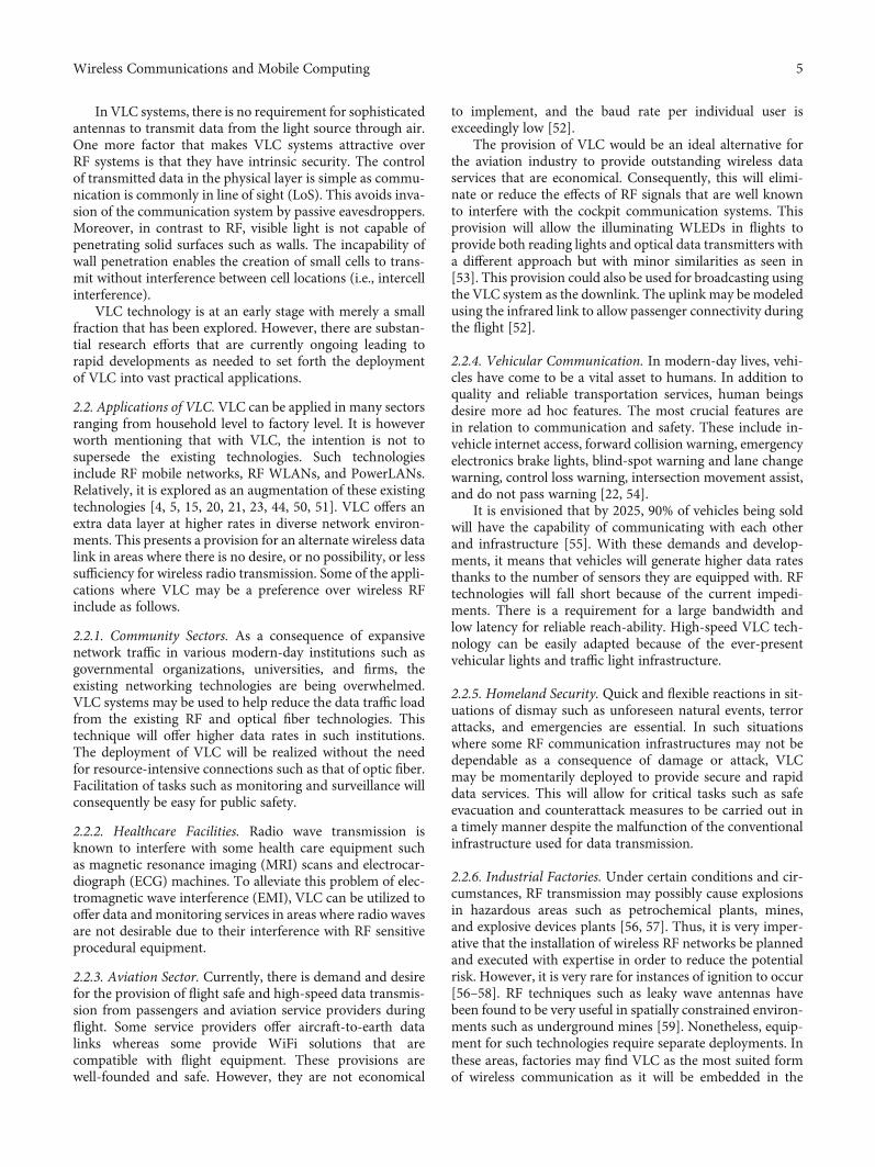

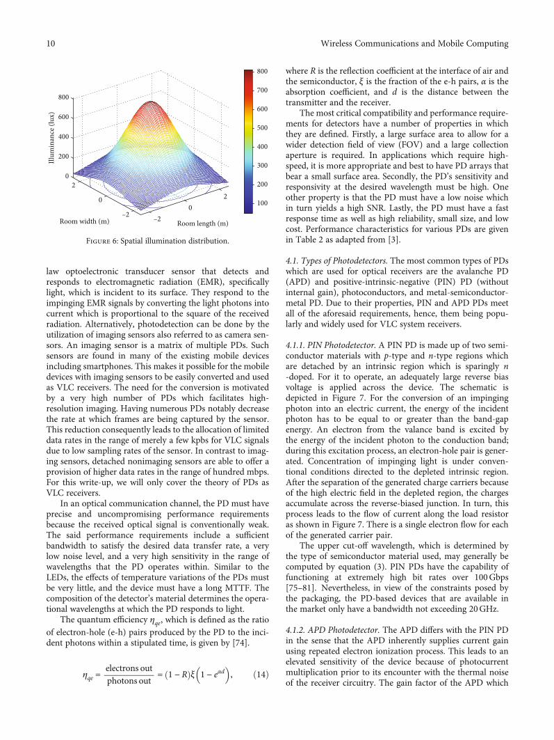


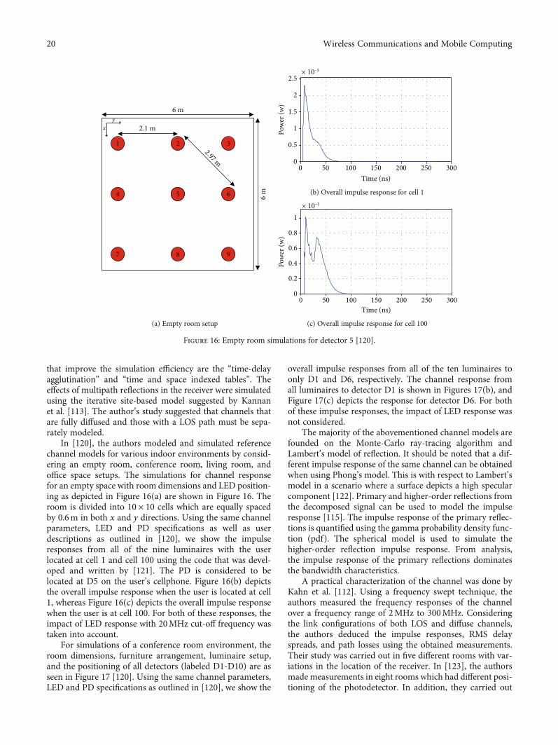
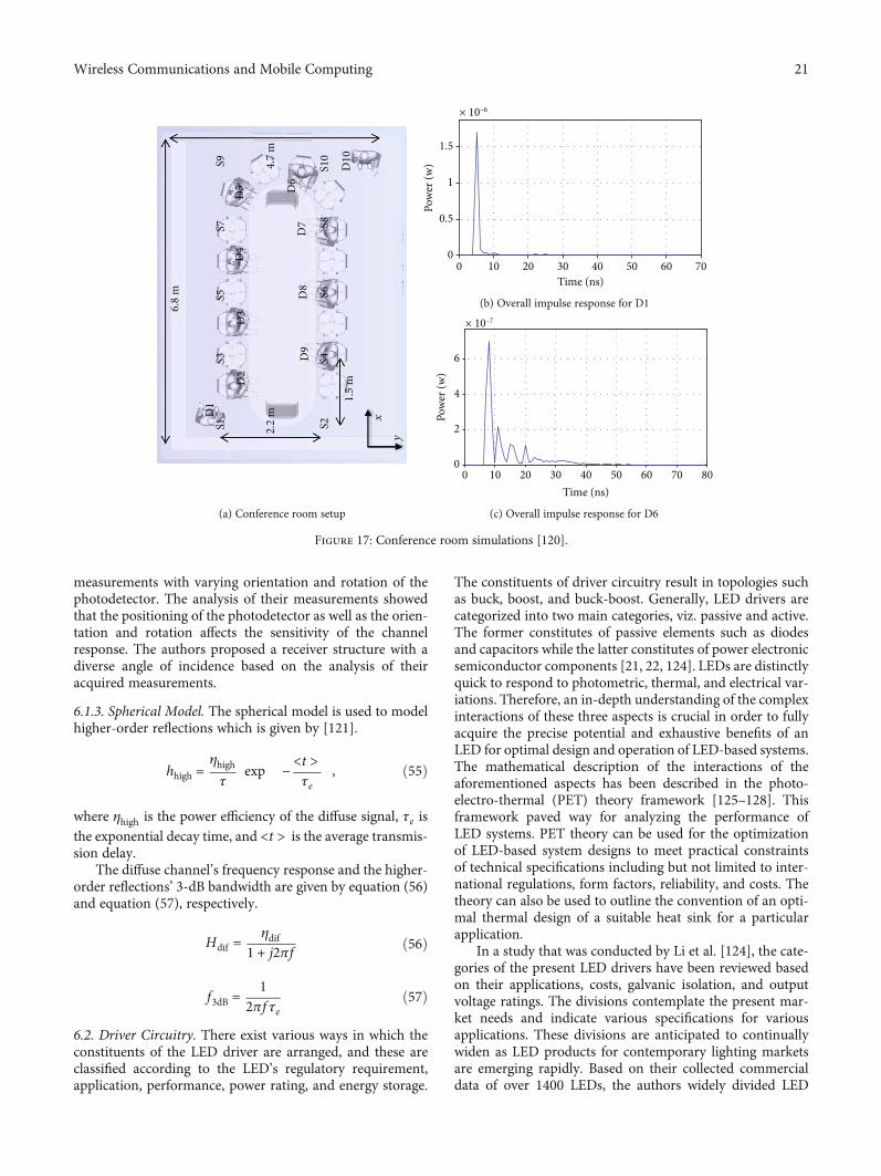


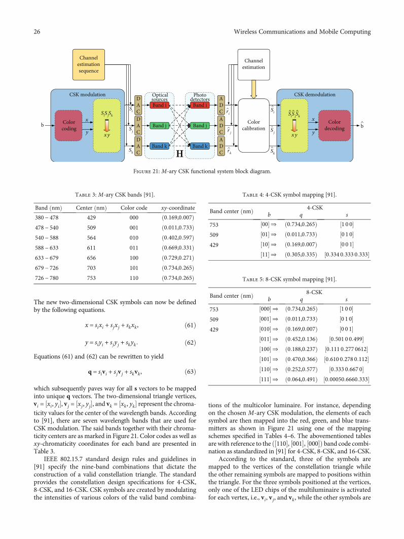

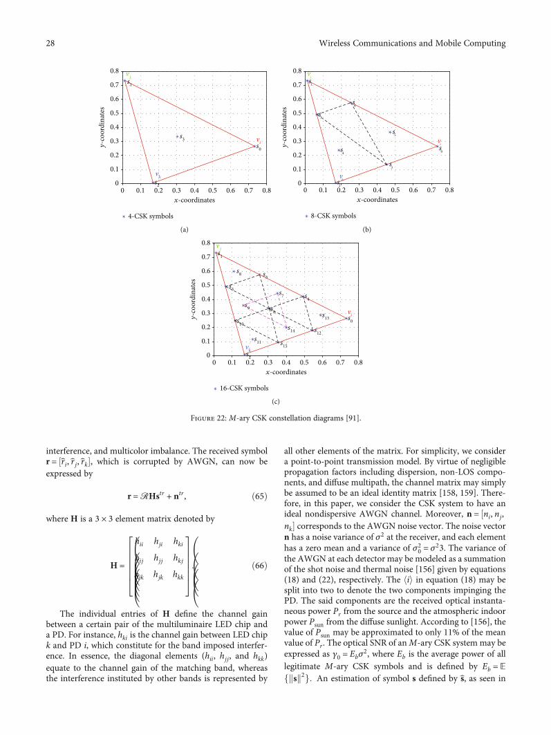

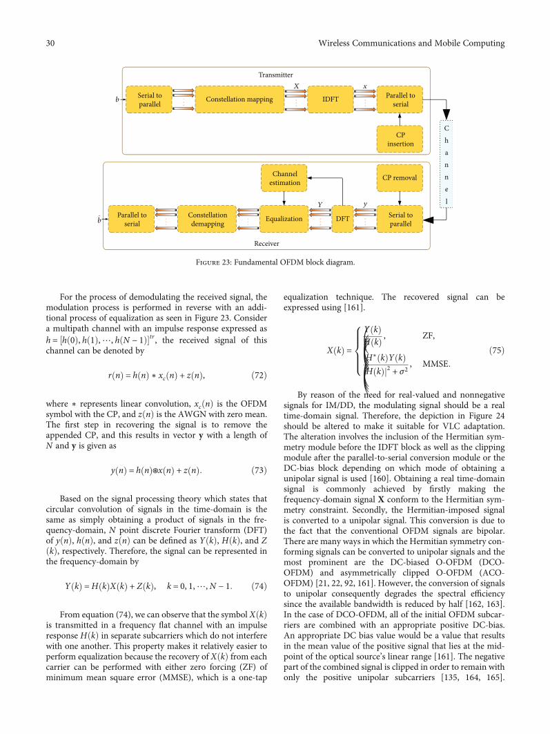


![Indoor MIMO Visible Light Communications: Novel Angle ... MIMO Visible Light... · technology [6]. Besides, VLC uses the visible light spectrum which is unregulated and license-free](https://static.fdocuments.net/doc/165x107/5fd68c11806b8407245ac1b8/indoor-mimo-visible-light-communications-novel-angle-mimo-visible-light.jpg)


