INDIAN INSTITUTE OF TECHNOLOGY ROORKEE …textofvideo.nptel.ac.in/103107127/lec4.pdf · So as for...
17
INDIAN INSTITUTE OF TECHNOLOGY ROORKEE NPTEL NPTEL ONLINE CERTIFICATION COURSE Unit Operations of Particulate Matter Lec-04 Centrifugal Sedimentation and Equipment (Part - 1) Dr. Shabina Khanam Department of Chemical Engineering Indian Institute of technology Roorkee Welcome to the 4 th lecture of week 1 this is about centrifugal sedimentation and industrial equipment used for sedimentation process this particular lecture is divided in two parts that is lecture 4 and lecture 5 in lecture 4 I will speak about centrifugal Sedimentation and in lecture we will discuss industrial Equipment. So let us start with centrifugal Sedimentation. Now what is centrifugal Sedimentation the centrifugal force you all understand that it is? (Refer Slide Time: 00:57) In radial direction so when centrifugal forces are involved in separation processes gravitational forces are overcome. Thus separation efficiency is enhanced significantly so what happens in centrifugal force that when we consider the sedimenter in usual sedimenter what happens the
Transcript of INDIAN INSTITUTE OF TECHNOLOGY ROORKEE …textofvideo.nptel.ac.in/103107127/lec4.pdf · So as for...
INDIAN INSTITUTE OF TECHNOLOGY ROORKEE
NPTEL
NPTEL ONLINE CERTIFICATION COURSE
Unit Operations of Particulate Matter
Lec-04Centrifugal Sedimentation and Equipment (Part - 1)
Dr. Shabina KhanamDepartment of Chemical EngineeringIndian Institute of technology Roorkee
Welcome to the 4th lecture of week 1 this is about centrifugal sedimentation and industrial
equipment used for sedimentation process this particular lecture is divided in two parts that is
lecture 4 and lecture 5 in lecture 4 I will speak about centrifugal Sedimentation and in lecture we
will discuss industrial Equipment. So let us start with centrifugal Sedimentation. Now what is
centrifugal Sedimentation the centrifugal force you all understand that it is?
(Refer Slide Time: 00:57)
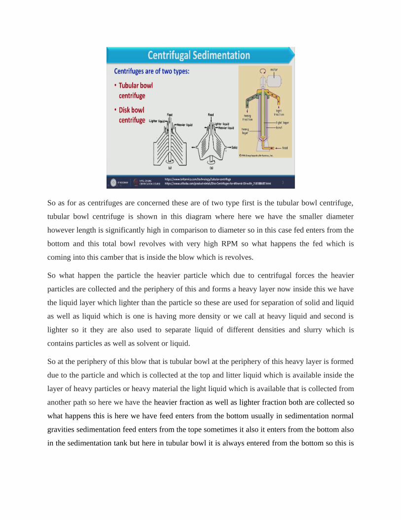
In radial direction so when centrifugal forces are involved in separation processes gravitational
forces are overcome. Thus separation efficiency is enhanced significantly so what happens in
centrifugal force that when we consider the sedimenter in usual sedimenter what happens the

particle starts settling down however in centrifugal sedimentation what happens the equipment
revolves with very high rpm.
So what happens the slurry which is available in that is collected that separated at the periphery
of this due to centrifugal forces now if we have heavier particles as well as the if we consider the
slurry which contains the solid particle as well as solvent so what happens solid particle will be
because of because they are more heavy so it will be collected at the wall of the equipment.
However at the inner layer we have the clear liquid so in that way the separation occurs, so that
is due to centrifugal action now if we consider the centrifugal forces as well as gravitational
forces the centrifugal forces are very high in comparison in gravitational forces so the ratio of
centrifugal forces to gravitational force that is ω2 r is due to centrifugal force and g is due to
gravitational force is often of the order of several thousands and is a major of separating power
of the machine incorporating centrifugal force.
So what happens because this centrifugal forces ratio with gravitational force is very high the
separation becomes very easy or very fast in comparison to centrifugal forces in comparison to
normal sedimentation which works under gravity, so separation can be carried out much more
rapidly in a centrifuge than under the action of gravity?
(Refer Slide Time: 03:17)
So as for as centrifuges are concerned these are of two type first is the tubular bowl centrifuge,
tubular bowl centrifuge is shown in this diagram where here we have the smaller diameter
however length is significantly high in comparison to diameter so in this case fed enters from the
bottom and this total bowl revolves with very high RPM so what happens the fed which is
coming into this camber that is inside the blow which is revolves.
So what happen the particle the heavier particle which due to centrifugal forces the heavier
particles are collected and the periphery of this and forms a heavy layer now inside this we have
the liquid layer which lighter than the particle so these are used for separation of solid and liquid
as well as liquid which is one is having more density or we call at heavy liquid and second is
lighter so it they are also used to separate liquid of different densities and slurry which is
contains particles as well as solvent or liquid.
So at the periphery of this blow that is tubular bowl at the periphery of this heavy layer is formed
due to the particle and which is collected at the top and litter liquid which is available inside the
layer of heavy particles or heavy material the light liquid which is available that is collected from
another path so here we have the heavier fraction as well as lighter fraction both are collected so
what happens this is here we have feed enters from the bottom usually in sedimentation normal
gravities sedimentation feed enters from the tope sometimes it also it enters from the bottom also
in the sedimentation tank but here in tubular bowl it is always entered from the bottom so this is
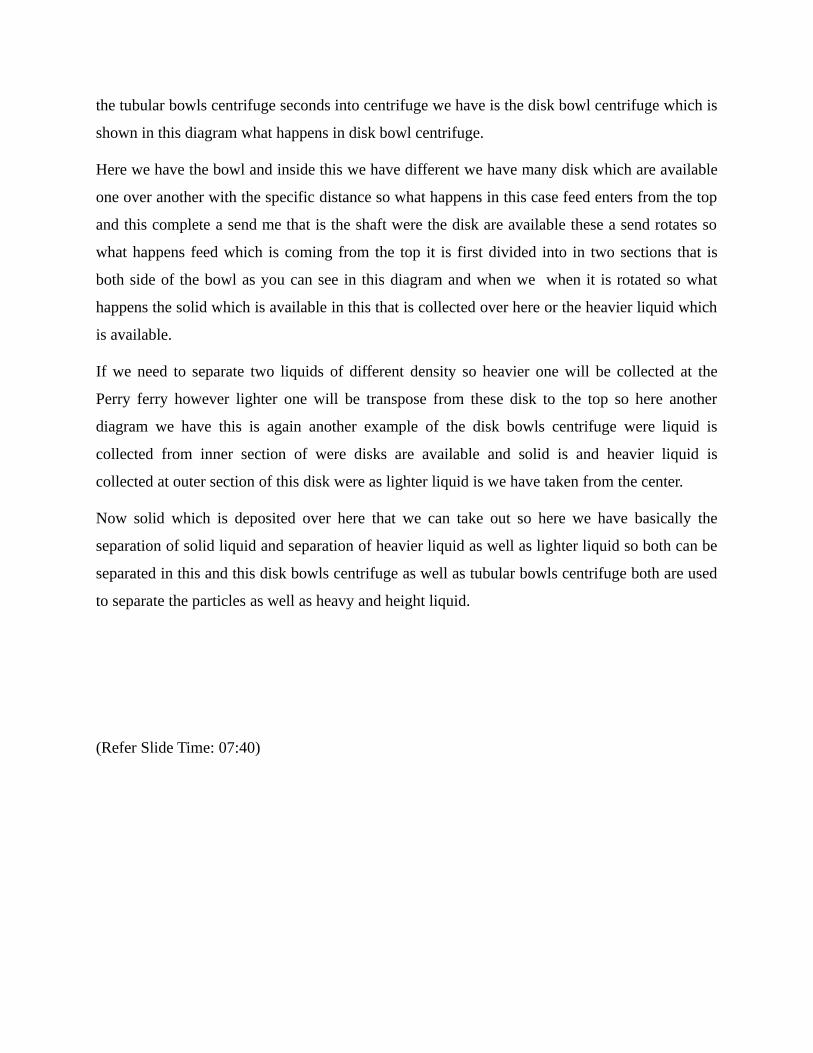
the tubular bowls centrifuge seconds into centrifuge we have is the disk bowl centrifuge which is
shown in this diagram what happens in disk bowl centrifuge.
Here we have the bowl and inside this we have different we have many disk which are available
one over another with the specific distance so what happens in this case feed enters from the top
and this complete a send me that is the shaft were the disk are available these a send rotates so
what happens feed which is coming from the top it is first divided into in two sections that is
both side of the bowl as you can see in this diagram and when we when it is rotated so what
happens the solid which is available in this that is collected over here or the heavier liquid which
is available.
If we need to separate two liquids of different density so heavier one will be collected at the
Perry ferry however lighter one will be transpose from these disk to the top so here another
diagram we have this is again another example of the disk bowls centrifuge were liquid is
collected from inner section of were disks are available and solid is and heavier liquid is
collected at outer section of this disk were as lighter liquid is we have taken from the center.
Now solid which is deposited over here that we can take out so here we have basically the
separation of solid liquid and separation of heavier liquid as well as lighter liquid so both can be
separated in this and this disk bowls centrifuge as well as tubular bowls centrifuge both are used
to separate the particles as well as heavy and height liquid.
(Refer Slide Time: 07:40)
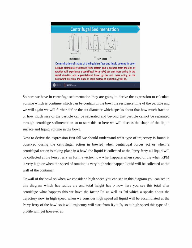
So here we have in centrifuge sedimentation they are going to derive the expression to calculate
volume which is continue which can be contain in the bowl the residence time of the particle and
we will again we will further define the cut diameter which speaks about that how much fraction
or how much size of the particle can be separated and beyond that particle cannot be separated
through centrifuge sedimentation so to start this so here we will discuss the shape of the liquid
surface and liquid volume in the bowl.
Now to derive the expression first fall we should understand what type of trajectory is found is
observed during the centrifugal action in bowled when centrifugal forces act or when a
centrifugal action is taking place in a bowl the liquid is collected at the Perry ferry all liquid will
be collected at the Perry ferry an form a vertex now what happens when speed of the when RPM
is very high or when the speed of rotation is very high what happen liquid will be collected at the
wall of the container.
Or wall of the bowl so when we consider a high speed you can see in this diagram you can see in
this diagram which has radius are and total height has b now here you see this total after
centrifuge what happens this we have the factor Ra as well as Rd which a speaks about the
trajectory now in high speed when we consider high speed all liquid will be accumulated at the
Perry ferry of the bowl so it will trajectory will start from RA to RB so at high speed this type of a
profile will get however at.
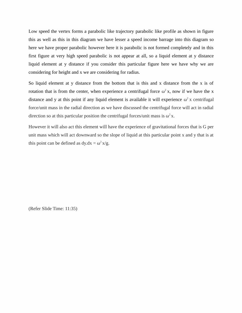
Low speed the vertex forms a parabolic like trajectory parabolic like profile as shown in figure
this as well as this in this diagram we have lesser a speed income barrage into this diagram so
here we have proper parabolic however here it is parabolic is not formed completely and in this
first figure at very high speed parabolic is not appear at all, so a liquid element at y distance
liquid element at y distance if you consider this particular figure here we have why we are
considering for height and x we are considering for radius.
So liquid element at y distance from the bottom that is this and x distance from the x is of
rotation that is from the center, when experience a centrifugal force ω2 x, now if we have the x
distance and y at this point if any liquid element is available it will experience ω2 x centrifugal
force/unit mass in the radial direction as we have discussed the centrifugal force will act in radial
direction so at this particular position the centrifugal forces/unit mass is ω2 x.
However it will also act this element will have the experience of gravitational forces that is G per
unit mass which will act downward so the slope of liquid at this particular point x and y that is at
this point can be defined as dy.dx = ω2 x/g.
(Refer Slide Time: 11:35)
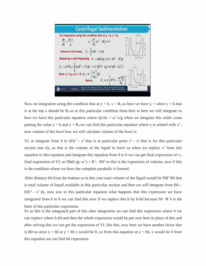
Now on integration using the condition that at y = b, x = R0 so here we have y = when y = b that
is at the top x should be R0 so at this particular condition from here to here we will integrate so
here we have this particular equation where dy/dx = ω2 x/g when we integrate this while come
putting the value y = b and x = R0 we can find this particular equation where y is related with x2 ,
now volume of the bowl how we will calculate volume of the bowl is.
VL is integrate from 0 to bΠr2 – x2 that is at particular point r2 – x2 that is for this particular
section into dy, so that is the volume of the liquid in bowl so when we replace x2 from this
equation to this equation and integrate this equation from 0 to b we can get final expression of vw
final expression of VL as Πb(b (g/ ω2 ) + R2 – R02 so this is the expression of volume, now if this
is the condition where we have the complete parabolic is formed.
After distance b0 from the bottom so in this case total volume of the liquid would be ΠR2 B0 that
is total volume of liquid available in this particular section and then we will integrate from B0 –
bΠr2 - x2 dy, now you in this particular equation what happens that this expression we have
integrated from 0 to b we can find this now if we replace this b by b-b0 because b0 b is the
limit of this particular expression.So as this is the integrated part of this after integration we can find this expression where b we
can replace where b-b0 and then the whole expression would be put over here in place of this and
after solving this we can get the expression of VL like this, now here we have another factor that
is B0 so since y = b0 at y = b0 x would be 0, so from this equation at y = b0, x would be 0 from
this equation we can find b0 expression.
And while putting this b0 into this we can calculate total volume which is available in this type
of container this type of centrifuge where volume can be in terms of all own parameter like bR0
ω etc, g ω all these we get fine so here using this expression we can calculate volume of the
liquid which is available in bowl, so here we will discuss the centrifugal sedimentation where
force balance will be discussed to calculate the residence time of the particle. (Refer Slide Time: 15:06)
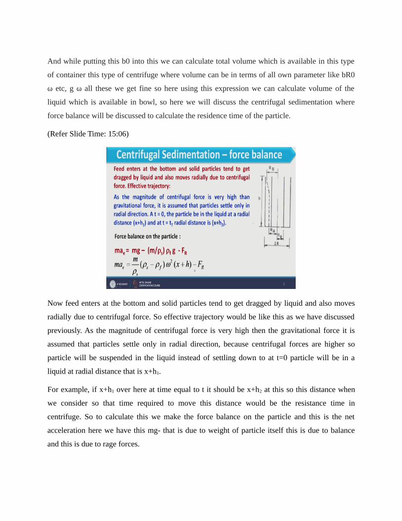
Now feed enters at the bottom and solid particles tend to get dragged by liquid and also moves
radially due to centrifugal force. So effective trajectory would be like this as we have discussed
previously. As the magnitude of centrifugal force is very high then the gravitational force it is
assumed that particles settle only in radial direction, because centrifugal forces are higher so
particle will be suspended in the liquid instead of settling down to at t=0 particle will be in a
liquid at radial distance that is x+h1.
For example, if x+h1 over here at time equal to t it should be x+h2 at this so this distance when
we consider so that time required to move this distance would be the resistance time in
centrifuge. So to calculate this we make the force balance on the particle and this is the net
acceleration here we have this mg- that is due to weight of particle itself this is due to balance
and this is due to rage forces.
Now as this equation is valid when gravidity force will act in this case as centrifugal forces
dominate so we will replace g value with ω2 x, so here mae would be equal to m/ρs ρs- ρf ω2
(x+h)-FR (x+h) is the distance at which particle is available in the solution. Now here we have
different expression for FR and we can define different conditions for laminar as well as turbulent
flow.
(Refer Slide Time: 16:59)
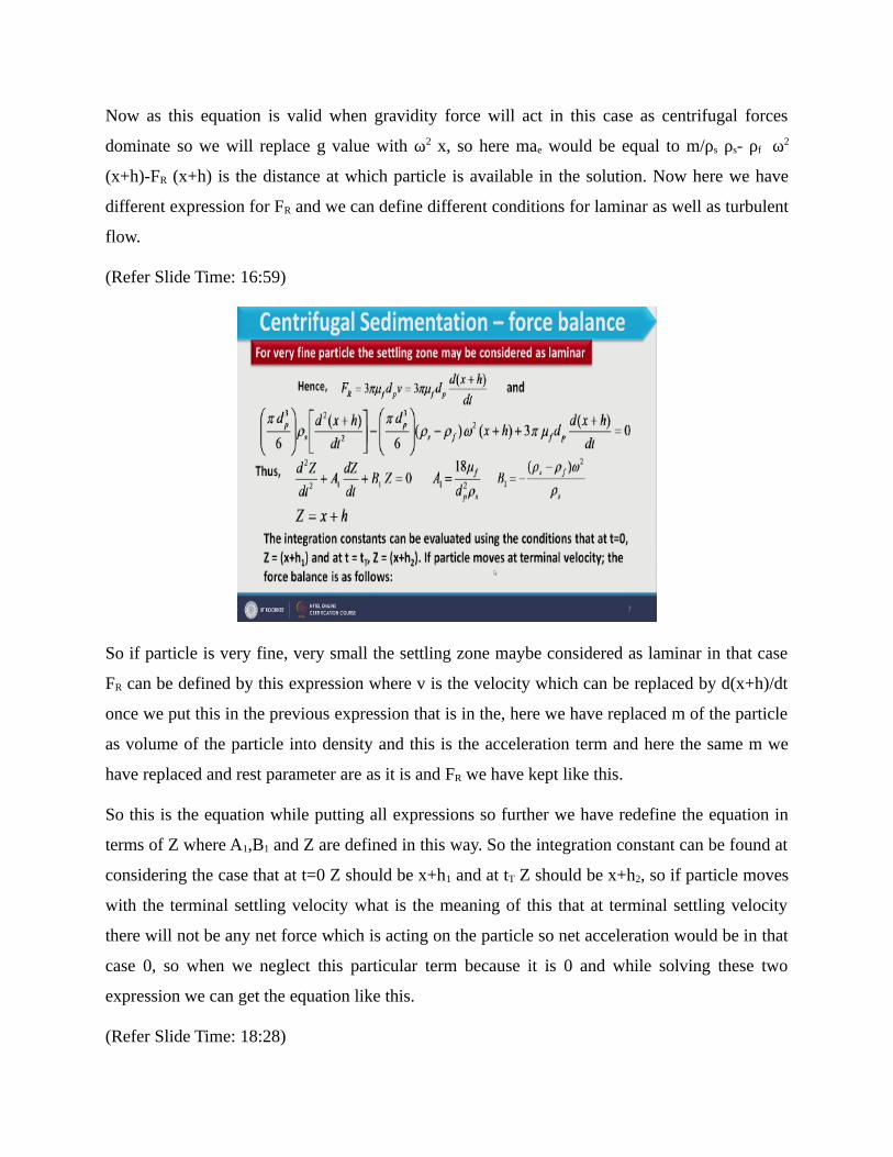
So if particle is very fine, very small the settling zone maybe considered as laminar in that case
FR can be defined by this expression where v is the velocity which can be replaced by d(x+h)/dt
once we put this in the previous expression that is in the, here we have replaced m of the particle
as volume of the particle into density and this is the acceleration term and here the same m we
have replaced and rest parameter are as it is and FR we have kept like this.
So this is the equation while putting all expressions so further we have redefine the equation in
terms of Z where A1,B1 and Z are defined in this way. So the integration constant can be found at
considering the case that at t=0 Z should be x+h1 and at tT Z should be x+h2, so if particle moves
with the terminal settling velocity what is the meaning of this that at terminal settling velocity
there will not be any net force which is acting on the particle so net acceleration would be in that
case 0, so when we neglect this particular term because it is 0 and while solving these two
expression we can get the equation like this.
(Refer Slide Time: 18:28)

That is d(x+h)/dt in this form so that is the case when no acceleration is applicable. Integrating
above equation from t=0 to t=tT we can find the residence time of the particle in the centrifuge so
where tT is the residence time of the particle in the centrifuge. Similarly if we have larger particle
we assume a turbulent flow where drag co-efficient is we are considering as kT so this is the
equation for FR that is FR=AKf A is the projected area of particle K is the kinetic energy per unit
volume of the particle and f is the drag co-efficient that is kT in this case.
So while putting this FR where you can get like this again for no acceleration condition we can
find this expression where the whole parameter, whole expression is converted into KC2.
(Refer Slide Time: 19:30)

So in that case again while integrating we can get residence time of the particle in this form,
further for very high speed vertical liquid surface is obtained as shown in the figure like here we
have the this way so in that case initial x+h1 should be RA and x+h2 should be RB, so while for
this case when we consider we have residence time of particle for laminar zone this so here this
all this we will replaced with RA and RB.
(Refer Slide Time: 20:09)
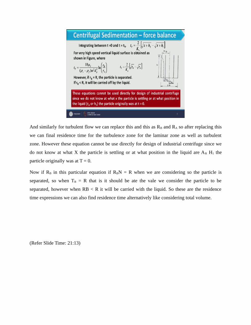
And similarly for turbulent flow we can replace this and this as RB and RA so after replacing this
we can final residence time for the turbulence zone for the laminar zone as well as turbulent
zone. However these equation cannot be use directly for design of industrial centrifuge since we
do not know at what X the particle is settling or at what position in the liquid are AR H1 the
particle originally was at T = 0.
Now if RB in this particular equation if RBN = R when we are considering so the particle is
separated, so when TB = R that is it should be ate the vale we consider the particle to be
separated, however when RB < R it will be carried with the liquid. So these are the residence
time expressions we can also find residence time alternatively like considering total volume.
(Refer Slide Time: 21:13)

Which is volume of the liquid in the bowl divided by the flow rate that volumetric flow rate
duration of these two will give the residence time where Q is the rate of flow of liquid through
the bowl and here we have to defined one parameter that is very important parameter and that is
called as the cut size the cut size we can denote as DPC of the particle for centrifugation and it is
define as the particle of size DPC will settle through a distance equal to ½ the thickness of the
liquid layer inside the bowl.
During its residence time in the bowl thus the cut size of the particle settles through a distance R
– R0 / 2 within the residence time TT, so what is the meaning of this that when residence time
when we consider the cur diameter of the particle it means it will settle at this distance so particle
which is lesser than the DPC that will not be settle and particle which are higher in size then DPC
will be settle because they will moved in this particular distance.
In that case RA should be R – R0 / 2 so this is the total distance total radios of the bowl and this is
the distance they will move so while solving this we can consider this particular expression
where RA, so RA is nothing but the distance of half of the layer it will be RA and Rb would be the
R in that case if we considered the cut diameter.So for laminar zone we can calculate QC like this and now how this expression we have obtained
is we have this Q value and this QC we have defined here if you consider the previous slide her
we have the TT expression once we put TT expression in this and then solving it for Q we can
obtain the equation like this.

(Refer Slide Time: 23:28)
Similarly for turbulent zone we have this expression where KC’ we can define like this so how we
can defined these equation because we have already residence time in laminar zone as well as in
turbulence zone so that expression we have put to calculate the q value because we have two
expression to TT and then we can replace and then calculated Q for laminar as well as turbulent.
(Refer Slide Time: 23:57)

So here we have the example of centrifugal sedimentation where a centrifuge with 70cm
diameter and 35cm height is being operated at 1000rpm. It is employed to clarify a slurry
consists of solid particle with specific gravity 1.5 in a liquid of specific gravity 1.2 and viscosity
4cp at 150m3/h, if 5 cm thick liquid layer is formed inside the bowl and having following
particles size distribution compute what percent of particles will be separated in this centrifuge.
So here we have the problem and the particle size data will be available over here that particle
size minus and plus and all fraction which is available on this particular screen. So we have use
this data we have calculate the percentage of particle size which can be separated so first of all
what we have calculate is the all flow rates we know that is the Q value we know so we can
calculate the cut diameter of the particle and we will see that how many particles are available
above to this.
So all those particle percent of particle will be separated and particle which are lesser than the
cut diameter that should not be separated, so first of all we have to calculate the cut diameter.
(Refer Slide Time: 25:31)
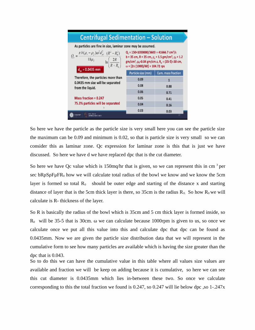
So here we have the particle as the particle size is very small here you can see the particle size
the maximum can be 0.09 and minimum is 0.02, so that is particle size is very small so we can
consider this as laminar zone. Qc expression for laminar zone is this that is just we have
discussed. So here we have d we have replaced dpc that is the cut diameter.
So here we have Qc value which is 150mq/hr that is given, so we can represent this in cm 3 per
sec bRρSρFμFR0 how we will calculate total radius of the bowl we know and we know the 5cm
layer is formed so total R0 should be outer edge and starting of the distance x and starting
distance of layer that is the 5cm thick layer is there, so 35cm is the radius R0. So how R0 we will
calculate is R- thickness of the layer.
So R is basically the radius of the bowl which is 35cm and 5 cm thick layer is formed inside, so
R0 will be 35-5 that is 30cm. ω we can calculate because 1000rpm is given to us, so once we
calculate once we put all this value into this and calculate dpc that dpc can be found as
0.0435mm. Now we are given the particle size distribution data that we will represent in the
cumulative form to see how many particles are available which is having the size greater than the
dpc that is 0.043.So to do this we can have the cumulative value in this table where all values size values are
available and fraction we will be keep on adding because it is cumulative, so here we can see
this cut diameter is 0.0435mm which lies in-between these two. So once we calculate
corresponding to this the total fraction we found is 0.247, so 0.247 will lie below dpc ,so 1-.247x
100= 75.3% particle will be separated because their size would be greater than the size of the cut
diameter per which we just calculated.
So in this particular example 75.3% particle will be separated so in this way we can derive the
equation center figure sedimentation and we can use this for the calculation purpose and
calculate how many part5icles are available etc. so that is all about center figure sedimentation.
So for this session we have to stop over here in next session we will continue with and we will
discuss the industrial equipment available for sedimentation, so that is all for now. Thank you.
For Further Details Contact
Coordinator, Educational Technology CellIndian Institute of Technology Roorkee
Roorkee-247 667E Mail: [email protected], [email protected]
Website: www.iitr.ac.in/centers/ETC, www.nptel.ac.in
Production TeamSarath. K. V
Jithin. KPankaj Saini
Arun. SMohan Raj. S
Camera, Graphics, Online Editing & Post ProductionBinoy. V. P
NPTEL CoordinatorProf. B. K. Gandhi
An Eductaional Technology Cell