Indexing grazing-incidence X-ray diffraction patterns of ...
12
research papers 428 https://doi.org/10.1107/S1600576719003029 J. Appl. Cryst. (2019). 52, 428–439 Received 12 November 2018 Accepted 27 February 2019 Edited by V. Holy ´, Charles University, Prague, Czech Republic and CEITEC at Masaryk University, Brno, Czech Republic Keywords: grazing incidence X-ray diffraction; indexing; fibre texture; uni-planar texture; mathematical crystallography. Indexing grazing-incidence X-ray diffraction patterns of thin films: lattices of higher symmetry Josef Simbrunner, a * Sebastian Hofer, b Benedikt Schrode, b Yves Garmshausen, c Stefan Hecht, c Roland Resel b and Ingo Salzmann d a Department of Neuroradiology, Vascular and Interventional Radiology, Medical University Graz, Auenbruggerplatz 9, Graz, 8036, Austria, b Institute of Solid State Physics, Technical University Graz, Petersgasse 16, Graz, 8010, Austria, c Department of Chemistry and IRIS Adlershof, Humboldt-Universita ¨t zu Berlin, Brook-Taylor-Strasse 2, Berlin, 12489, Germany, and d Department of Physics, Department of Chemistry and Biochemistry, Centre for Research in Molecular Modeling (CERMM), Centre for Nanoscience Research (CeNSR), Concordia University, 7141 Sherbrooke Street W., SP 265-20, Montreal, Quebec, Canada H4B 1R6. *Correspondence e-mail: [email protected] Grazing-incidence X-ray diffraction studies on organic thin films are often performed on systems showing fibre-textured growth. However, indexing their experimental diffraction patterns is generally challenging, especially if low- symmetry lattices are involved. Recently, analytical mathematical expressions for indexing experimental diffraction patterns of triclinic lattices were provided. In the present work, the corresponding formalism for crystal lattices of higher symmetry is given and procedures for applying these equations for indexing experimental data are described. Two examples are presented to demonstrate the feasibility of the indexing method. For layered crystals of the prototypical organic semiconductors diindenoperylene and (ortho-difluoro)sexiphenyl, as grown on highly oriented pyrolytic graphite, their yet unknown unit-cell parameters are determined and their crystallographic lattices are identified as monoclinic and orthorhombic, respectively. 1. Introduction Crystalline thin films are often characterized by grazing-inci- dence X-ray diffraction (GIXD) owing to the high surface sensitivity of the technique. A schematic drawing of the experimental method is shown in Fig. 1(a). To achieve this surface sensitivity, the angle of incidence of the primary beam relative to the sample surface ( i ) is chosen close to the critical angle of total external reflection, and the scattered X-ray beam encloses an in-plane angle f , as well as an out-of-plane angle f relative to the surface. The primary X-ray beam, described by the wavevector k 0 , and the scattered beam k determine the scattering vector q by q = k k 0 . In this geometry the in-plane component q xy and the out-of-plane component q z of q are given by q xy ¼ 2% ! cos 2 i þ cos 2 f 2 cos i cos f cos f 1=2 ð1Þ and q z ¼ 2% ! sin i þ sin f ð Þ: ð2Þ A key direction in reciprocal space is the z direction at q xy = 0, which reveals the orientation of crystals relative to the substrate surface. In the important case of crystalline fibre- textured films, it defines the crystallographic plane of the thin- film crystallites which is parallel to the substrate surface (i.e. ISSN 1600-5767
Transcript of Indexing grazing-incidence X-ray diffraction patterns of ...

research papers
428 https://doi.org/10.1107/S1600576719003029 J. Appl. Cryst. (2019). 52, 428–439
Received 12 November 2018
Accepted 27 February 2019
Edited by V. Holy, Charles University, Prague,
Czech Republic and CEITEC at Masaryk
University, Brno, Czech Republic
Keywords: grazing incidence X-ray diffraction;
indexing; fibre texture; uni-planar texture;
mathematical crystallography.
Indexing grazing-incidence X-ray diffractionpatterns of thin films: lattices of higher symmetry
Josef Simbrunner,a* Sebastian Hofer,b Benedikt Schrode,b Yves Garmshausen,c
Stefan Hecht,c Roland Reselb and Ingo Salzmannd
aDepartment of Neuroradiology, Vascular and Interventional Radiology, Medical University Graz, Auenbruggerplatz 9,
Graz, 8036, Austria, bInstitute of Solid State Physics, Technical University Graz, Petersgasse 16, Graz, 8010, Austria,cDepartment of Chemistry and IRIS Adlershof, Humboldt-Universitat zu Berlin, Brook-Taylor-Strasse 2, Berlin, 12489,
Germany, and dDepartment of Physics, Department of Chemistry and Biochemistry, Centre for Research in Molecular
Modeling (CERMM), Centre for Nanoscience Research (CeNSR), Concordia University, 7141 Sherbrooke Street W., SP
265-20, Montreal, Quebec, Canada H4B 1R6. *Correspondence e-mail: [email protected]
Grazing-incidence X-ray diffraction studies on organic thin films are often
performed on systems showing fibre-textured growth. However, indexing their
experimental diffraction patterns is generally challenging, especially if low-
symmetry lattices are involved. Recently, analytical mathematical expressions
for indexing experimental diffraction patterns of triclinic lattices were provided.
In the present work, the corresponding formalism for crystal lattices of higher
symmetry is given and procedures for applying these equations for indexing
experimental data are described. Two examples are presented to demonstrate
the feasibility of the indexing method. For layered crystals of the prototypical
organic semiconductors diindenoperylene and (ortho-difluoro)sexiphenyl, as
grown on highly oriented pyrolytic graphite, their yet unknown unit-cell
parameters are determined and their crystallographic lattices are identified as
monoclinic and orthorhombic, respectively.
1. Introduction
Crystalline thin films are often characterized by grazing-inci-
dence X-ray diffraction (GIXD) owing to the high surface
sensitivity of the technique. A schematic drawing of the
experimental method is shown in Fig. 1(a). To achieve this
surface sensitivity, the angle of incidence of the primary beam
relative to the sample surface (�i) is chosen close to the critical
angle of total external reflection, and the scattered X-ray
beam encloses an in-plane angle �f, as well as an out-of-plane
angle �f relative to the surface. The primary X-ray beam,
described by the wavevector k0, and the scattered beam k
determine the scattering vector q by q = k � k0. In this
geometry the in-plane component qxy and the out-of-plane
component qz of q are given by
qxy ¼2�
�cos2 �i þ cos2 �f � 2 cos�i cos�f cos �f
� �1=2ð1Þ
and
qz ¼2�
�sin �i þ sin �fð Þ: ð2Þ
A key direction in reciprocal space is the z direction at qxy =
0, which reveals the orientation of crystals relative to the
substrate surface. In the important case of crystalline fibre-
textured films, it defines the crystallographic plane of the thin-
film crystallites which is parallel to the substrate surface (i.e.
ISSN 1600-5767
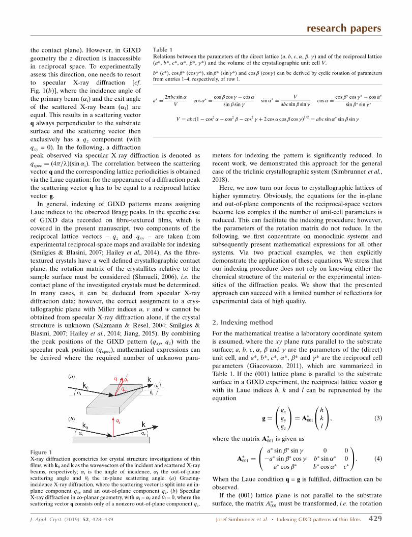
the contact plane). However, in GIXD
geometry the z direction is inaccessible
in reciprocal space. To experimentally
assess this direction, one needs to resort
to specular X-ray diffraction [cf.
Fig. 1(b)], where the incidence angle of
the primary beam (�i) and the exit angle
of the scattered X-ray beam (�f) are
equal. This results in a scattering vector
q always perpendicular to the substrate
surface and the scattering vector then
exclusively has a qz component (with
qxy = 0). In the following, a diffraction
peak observed via specular X-ray diffraction is denoted as
qspec ¼ ð4�=�Þðsin �iÞ. The correlation between the scattering
vector q and the corresponding lattice periodicities is obtained
via the Laue equation: for the appearance of a diffraction peak
the scattering vector q has to be equal to a reciprocal lattice
vector g.
In general, indexing of GIXD patterns means assigning
Laue indices to the observed Bragg peaks. In the specific case
of GIXD data recorded on fibre-textured films, which is
covered in the present manuscript, two components of the
reciprocal lattice vectors – qz and qxy – are taken from
experimental reciprocal-space maps and available for indexing
(Smilgies & Blasini, 2007; Hailey et al., 2014). As the fibre-
textured crystals have a well defined crystallographic contact
plane, the rotation matrix of the crystallites relative to the
sample surface must be considered (Shmueli, 2006), i.e. the
contact plane of the investigated crystals must be determined.
In many cases, it can be deduced from specular X-ray
diffraction data; however, the correct assignment to a crys-
tallographic plane with Miller indices u, v and w cannot be
obtained from specular X-ray diffraction alone, if the crystal
structure is unknown (Salzmann & Resel, 2004; Smilgies &
Blasini, 2007; Hailey et al., 2014; Jiang, 2015). By combining
the peak positions of the GIXD pattern (qxy, qz) with the
specular peak position (qspec), mathematical expressions can
be derived where the required number of unknown para-
meters for indexing the pattern is significantly reduced. In
recent work, we demonstrated this approach for the general
case of the triclinic crystallographic system (Simbrunner et al.,
2018).
Here, we now turn our focus to crystallographic lattices of
higher symmetry. Obviously, the equations for the in-plane
and out-of-plane components of the reciprocal-space vectors
become less complex if the number of unit-cell parameters is
reduced. This can facilitate the indexing procedure; however,
the parameters of the rotation matrix do not reduce. In the
following, we first concentrate on monoclinic systems and
subsequently present mathematical expressions for all other
systems. Via two practical examples, we then explicitly
demonstrate the application of these equations. We stress that
our indexing procedure does not rely on knowing either the
chemical structure of the material or the experimental inten-
sities of the diffraction peaks. We show that the presented
approach can succeed with a limited number of reflections for
experimental data of high quality.
2. Indexing method
For the mathematical treatise a laboratory coordinate system
is assumed, where the xy plane runs parallel to the substrate
surface; a, b, c, �, � and � are the parameters of the (direct)
unit cell, and a*, b*, c*, �*, �* and �* are the reciprocal cell
parameters (Giacovazzo, 2011), which are summarized in
Table 1. If the (001) lattice plane is parallel to the substrate
surface in a GIXD experiment, the reciprocal lattice vector g
with its Laue indices h, k and l can be represented by the
equation
g ¼
gx
gy
gz
0@
1A ¼ A�001
h
k
l
0@
1A; ð3Þ
where the matrix A�001 is given as
A�001 ¼
a� sin �� sin � 0 0
�a� sin �� cos � b� sin �� 0
a� cos�� b� cos �� c�
0@
1A: ð4Þ
When the Laue condition q = g is fulfilled, diffraction can be
observed.
If the (001) lattice plane is not parallel to the substrate
surface, the matrix A�001 must be transformed, i.e. the rotation
research papers
J. Appl. Cryst. (2019). 52, 428–439 Josef Simbrunner et al. � Indexing GIXD patterns of thin films 429
Table 1Relations between the parameters of the direct lattice (a, b, c, �, �, �) and of the reciprocal lattice(a*, b*, c*, �*, �*, �*) and the volume of the crystallographic unit cell V.
b* (c*), cos�* (cos�*), sin�* (sin�*) and cos� (cos�) can be derived by cyclic rotation of parametersfrom entries 1–4, respectively, of row 1.
a� ¼2�bc sin�
Vcos�� ¼
cos� cos � � cos�
sin� sin �sin�� ¼
V
abc sin� sin �cos� ¼
cos�� cos �� � cos��
sin�� sin ��
V ¼ abcð1� cos2 �� cos2 �� cos2 � þ 2 cos� cos� cos �Þ1=2¼ abc sin�� sin� sin �
Figure 1X-ray diffraction geometries for crystal structure investigations of thinfilms, with k0 and k as the wavevectors of the incident and scattered X-raybeams, respectively; �i is the angle of incidence, �f the out-of-planescattering angle and �f the in-plane scattering angle. (a) Grazing-incidence X-ray diffraction, where the scattering vector is split into an in-plane component qxy and an out-of-plane component qz. (b) SpecularX-ray diffraction in co-planar geometry, with �i = �f and �f = 0, where thescattering vector q consists only of a nonzero out-of-plane component qz.

matrix of the thin-film crystallites relative to the substrate
surface has to be considered (Shmueli, 2006). In particular, it
has to be rotated around the zone axis which is defined by the
(001) plane and the new contact plane (uvw). Then the reci-
procal-space vector with the Laue/Miller indices u, v and w,
guvw, is perpendicular to the contact plane. Its magnitude is
purely out of plane and corresponds to the specular scan, gspec.
Furthermore, the out-of-plane component gz and in-plane
component gxy of any reciprocal-space vector ghkl can be
determined by their scalar product and vector (cross) product
with guvw, respectively. As the magnitude of a vector and the
scalar product of two vectors are both rotation invariant, the
unrotated expressions, i.e. equation (3), for ghkl and guvw are
sufficient. Therefore, the following expressions result:
gzgspec ¼ ghkl � guvw
�� ��¼ huz2
a þ kvz2b � hvþ kuð Þzazb cos �
þ ua� cos�� þ vb� cos �� þ wc�ð Þ
� ha� cos�� þ kb� cos �� þ lc�ð Þ ð5Þ
with za ¼ 2�=ða sin �Þ, zb ¼ 2�=ðb sin �Þ,
gspec ¼ guvw
�� �� ¼ �u2z2a þ v2z2
b � 2uvzazb cos �
þ ua� cos �� þ vb� cos�� þ wc�ð Þ2�1=2
ð6Þ
and
g2xyg2
spec ¼ ghkl � guvw
�� ��2 ¼ 2�ð Þ4
V2
�kw� lvð Þ
2a2 þ hw� luð Þ2b2
þ hv� kuð Þ2c2 þ 2 ku� hvð Þ hw� luð Þbc cos�
þ 2 hv� kuð Þ kw� lvð Þac cos�
þ 2 hw� luð Þ lv� kwð Þab cos ��; ð7Þ
where the volume is
V ¼ abc sin �� sin � sin �: ð8Þ
Furthermore, from equation (3) the length of the vector
jghklj, gxyz, can be determined as
g2xyz ¼ h2z2
a þ k2z2b � 2hkzazb cos �
þ ha� cos �� þ kb� cos�� þ lc�ð Þ2: ð9Þ
Using equations (5) and (6), equation (9) can be rewritten
as
g2xyz ¼ h2z2
a þ k2z2b � 2hkzazb cos �
þgzgspec � huz2
a þ kvz2b � hvþ kuð Þzazb cos �
� �� �2
g2spec � u2z2
a þ v2z2b � 2uvzazb cos �
� � ; ð10Þ
and by algebraic transformations the following expression can
be derived:
g2xyg2
spec ¼ z2a u2g2
xy þ hgspec � ugz
� �2h iþ z2
b v2g2xy þ kgspec � vgz
� �2h i
� 2zazb cos � uvg2xy þ hgspec � ugz
� �kgspec � vgz
� �� �� hv� kuð Þ
2z2az2
b sin2 �: ð11Þ
As a result of symmetry relationships, further analogous
expressions for the cell parameter triples (a, c, �) and (b, c, �)
and their corresponding Miller and Laue indices can be
derived.
From equations (5) and (6) the following expression can be
obtained:
ha� cos �� þ kb� cos�� þ lc�
¼gzgspec � huz2
a � kvz2b þ hvþ kuð Þzazb cos �
ðg2spec � u2z2
a � v2z2a þ 2uvzazb cos �Þ1=2
: ð12Þ
From equation (12), the residual unit-cell parameters c, �, �and the Laue indices l can be determined (Truger et al., 2016).
Analogously, the following equation is valid:
ha� cos �� þ kb� þ lc� cos��
¼
"gzgspec � hu
2�
a sin �
2
� lw2�
c sin �
2
þ hwþ luð Þ2�
a sin �
2�
c sin �cos �
#,"
g2spec � u2 2�
a sin �
2
� w2 2�
c sin �
2
þ 2uw2�
a sin�
2�
c sin�cos�
#1=2
: ð13Þ
In a monoclinic system (� = � = 90�), equation (11) reduces
to
g2xyg2
spec ¼ 2�=að Þ2
u2g2xy þ hgspec � ugz
� �2h i
þ 2�=bð Þ2
v2g2xy þ kgspec � vgz
� �2h i
� hv� kuð Þ2 2�=að Þ
2 2�=bð Þ2: ð14Þ
Equation (14) comprises – in addition to the rotation
parameters u and v – only the lattice parameters a and b, as
well as the Laue indices h and k. This facilitates the mathe-
matical analysis, where the integer variables can be varied and
only two real unknowns must be calculated.
In rare cases, if the net planes oriented parallel to the
substrate surface have a weak structure factor, which inhibits
the acquisition of specular diffraction data (Djuric et al., 2012),
gspec must be treated as an additional real unknown parameter,
which necessitates a more extensive numerical analysis. In the
most general case, if no contact plane exists, u, v and w are
non-integers. In this case it is preferable to use an alternative
notation of the rotation matrix (see Appendix A).
For calculating the remaining unit-cell parameters c, � and
the Laue indices l, the following expression results from
equation (12):
�h2�
acot �þ l
2�
c sin �¼
gzgspec � hu 2�=að Þ2� kv 2�=bð Þ
2
g2spec � u2 2�=að Þ
2� v2 2�=bð Þ
2� �1=2
:
ð15Þ
research papers
430 Josef Simbrunner et al. � Indexing GIXD patterns of thin films J. Appl. Cryst. (2019). 52, 428–439

Analogously to equation (14), by choosing related substitu-
tions on the basis of the symmetric properties of the relations
for gxyz, gxy, gz and gspec for the general (triclinic) case, the
following expressions hold:
g2xyg2
spec ¼ 2�=bð Þ2 v2g2
xy þ kgspec � vgz
� �2h i
þ 2�=cð Þ2
w2g2xy þ lgspec � wgz
� �2h i
� kw� lvð Þ2 2�=bð Þ
2 2�=cð Þ2; ð16Þ
g2xyg2
spec ¼2�
a sin �
2
u2g2xy þ hgspec � ugz
� �2h i
þ2�
c sin�
2
w2g2xy þ lgspec � wgz
� �2h i
� 22�
a sin �
2�
c sin �cos�
� uwg2xy þ hgspec � ugz
� �lgspec � wgz
� �� �� hw� luð Þ
2 2�
a sin �
22�
c sin�
2
sin2 �: ð17Þ
Furthermore, equation (13) reduces to
k2�
b¼
"gzgspec � hu
2�
a sin �
2
� lw2�
c sin �
2
þ hwþ luð Þ2�
a sin�
2�
c sin�cos�
#,"
g2spec � u2 2�
a sin �
2
� w2 2�
c sin�
2
þ 2uw2�
a sin �
2�
c sin �cos�
#1=2
: ð18Þ
For orthorhombic systems, the formulae are valid with � = 90�.
In Table 2 we summarize the mathematical expressions for
gxyz, gz, gxy and the volume V in triclinic, monoclinic and
orthorhombic systems. In tetragonal and cubic lattices, in
addition to � = 90�, a = b and a = b = c, respectively. In
Appendix B useful formulae for tetragonal, trigonal and
hexagonal systems are listed.
As every linear combination of the unit-cell vectors obeys
the Laue condition, the mathematical solutions are not unique
and include superlattices (Santoro et al., 1980). The definite
crystallographic solution, the reduced cell, is defined as the
cell that satisfies the conditions derived from the reduction
theory of quadratic forms (Niggli, 1928). The main conditions
for reduction require that the unit cell is based on the three
shortest vectors of the lattice; such a unit cell is then called a
Buerger cell (Buerger, 1957). However, this cell may not be
unique. An unambiguous unit cell is the ‘reduced cell’ defined
by Niggli; the criteria are listed in detail in International Tables
for Crystallography (De Wolff, 2016). In general, the criteria
for reduced cells demand that a2 � b2 � c2 and that the angles
are either acute (type I) or obtuse (type II). Geometrical
ambiguities, called lattice metric singularities, which generate
subcells of lower symmetry, may occur in some indexing cases
(Santoro & Mighell, 1970; Mighell, 2000). Such singularities
can often be easily detected from simple relationships
between the lattice parameters of the two cells (Boultif &
Louer, 2004).
In the following we turn to employing the formalism
derived above to determine the unit-cell parameters of two
prototypical organic semiconductors, which show as yet
unknown polymorphs if grown in thin films on substrates of
highly oriented pyrolytic graphite (HOPG).
3. Examples
3.1. Experiments
Thin films of diindenoperylene (DIP, C32H16) and of ortho-
difluorosexiphenyl (o-F2-6P, C36F2H24) were grown on freshly
cleaved HOPG (ZYA quality) by physical vapour deposition
in a high vacuum (final nominal film thickness 30 nm; base
pressure < 5 � 10�6 Pa). The films were characterized at
beamline W1 at the synchrotron radiation facility DORIS
(HASYLAB, Hamburg, Germany). GIXD experiments were
performed together with specular X-ray diffraction using a
goniometer in pseudo 2 + 2 geometry and a one-dimensional
detector (MYTHEN, Dectris). The wavelengths of the
primary radiation were 1.1796 and 1.1801 A for DIP and
o-F2-6P, respectively. GIXD experiments were performed
using incident angles of the primary beam relative to the
HOPG substrate of �i = 0.13 and 0.15� for DIP and o-F2-6P,
respectively. Reciprocal-space maps were recorded by keeping
the sample fixed and by performing a series of detector scans
along the in-plane scattering angle �f at differently fixed out-
of-plane scattering angles �f. The vertical mounting of the
detector allows the simultaneous measurement of ��f = 3.5�.
The diffraction pattern was transformed to reciprocal space
using the custom-made software PyGID (Moser, 2012). The
resulting reciprocal-space maps give the measured intensities
on a logarithmic scale by a colour code; the exact positions of
the Bragg peaks in terms of qxy and qz were determined by
Gaussian fits. The qz values of the peak positions were
corrected for refraction effects; maximum variations of 0.011
and 0.014 A�1 are obtained for DIP and o-F2-6P, respectively
(Resel et al., 2016).
3.2. Diindenoperylene
A specular scan of DIP crystals grown on a HOPG substrate
is shown in Fig. 2(a). The dominant diffraction peak at qz =
1.872 A�1 (d = 3.356 A) can be identified as the 002 peak of
the HOPG substrate. Forming the difference with the refer-
ence data recorded for the plain substrate (orange curve)
reveals a clear diffraction peak at qspec = 1.776 A�1, which is
assigned to the DIP adsorbate and corresponds to a lattice
spacing of 3.54 A. Note that a specular reflection from DIP at
the same position has been observed before for gold
substrates by Durr et al. (2003). The authors concluded on a
lying molecular orientation from their data and denoted this
polymorph as the � phase; however, no direct determination
research papers
J. Appl. Cryst. (2019). 52, 428–439 Josef Simbrunner et al. � Indexing GIXD patterns of thin films 431

of the unit cell by indexing GIXD reciprocal-space-map data
has been performed before. Our reciprocal-space map of DIP
on HOPG is shown in Fig. 2(b). Strong diffraction features of
the HOPG substrate are located along qxy = 2.94 A�1. Addi-
tionally, weak diffraction features at qxy = 2.24 A�1 /qz =
0.98 A�1 and at qxy = 2.34 A�1 /qz = 0.98 A�1 are also due to
the HOPG substrate. Bragg peaks at low q values (q2 = qxy2 +
qz2) were selected for the indexing procedure and lie at centres
of the triangles in Fig. 2(b). In total, we only used ten Bragg
peaks (based on their qxy and qz positions) together with the
Bragg peak of the specular diffraction pattern (qspec) for our
indexing procedure. Note that qspec, qxy and qz are experi-
mental results which describe specific components of the
scattering vector, while gspec, gxy and gz refer to these
components within the reciprocal lattice. According to the
Laue condition, the individual components of the scattering
vector q and of the reciprocal lattice vectors g must be equal.
As known crystal structures of DIP exhibit a monoclinic
lattice (Heinrich et al., 2007; Kowarik et al., 2009), in a first step
of indexing, equation (14) may be chosen. The combination of
Bragg peaks from the reciprocal-space map (qxy and qz) with
the peak from the specular scan (qspec) reduces the number of
parameters considerably to two integer numbers (instead of
three) for the Miller indices of the contact plane, to two
integer numbers (instead of three) for the Laue indices of each
Bragg peak, and to two real numbers (instead of four) for the
lattice constants. In theory, by using a quadratic equation, a
and b can be calculated from two independent pairs of (gxy, gz)
research papers
432 Josef Simbrunner et al. � Indexing GIXD patterns of thin films J. Appl. Cryst. (2019). 52, 428–439
Table 2Relations for the total length gxyz, the out-of-plane component gz and the in-plane component gxy of the reciprocal-space vectors with indices hkl and ofthe vector uvw (gspec) by using direct and reciprocal lattice parameters and the volume V in triclinic, monoclinic and orthorhombic systems.
Triclinic
g2xyz ¼ g2
x þ g2y þ g2
z ¼ h2a�2 þ k2b�2 þ l2c�2 þ 2hka�b� cos �� þ 2hla�c� cos�� þ 2klb�c� cos��
gzgspec ¼ hua�2 þ kvb�2 þ lwc�2 þ ðhvþ kuÞa�b� cos �� þ ðhwþ luÞa�c� cos�� þ ðkwþ lvÞb�c� cos��
gspec ¼ ðu2a�2 þ v2b�2 þ w2c�2 þ 2uva�b� cos �� þ 2uwa�c� cos�� þ 2vwb�c� cos��Þ1=2
g2xyg2
specV2 1
ð2�Þ4¼ ðkw� lvÞ2a2
þ ðhw� luÞ2b2þ ðhv� kuÞ2c2
þ 2ðku� hvÞðhw� luÞbc cos�þ 2ðhv� kuÞðkw� lvÞac cos�þ 2ðhw� luÞðlv� kwÞab cos �
V ¼ abcð1� cos2 �� cos2 �� cos2 � þ 2 cos� cos� cos �Þ1=2¼ abc sin�� sin� sin �
Monoclinic a 6¼ b 6¼ c, � = � = 90�
g2xyz ¼ h2 2�
a sin�
2
þ k2 2�
b
2
þ l2 2�
c sin�
2
� 2hl2�
a sin�
2�
c sin �cos�
gzgspec ¼ hu2�
a sin�
2
þ kv2�
b
2
þ lw2�
c sin�
2
� ðhwþ luÞ2�
a sin�
2�
c sin�cos�
gspec ¼ u2 2�
a sin�
2
þ v2 2�
b
2
þ w2 2�
c sin�
2
� 2uw2�
a sin�
2�
c sin�cos�
" #1=2
g2xyg2
spec ¼ ðkw� lvÞ22�
b
22�
c sin�
2
þ ðhw� luÞ22�
a sin�
22�
c sin�
2
sin2 �þ ðhv� kuÞ22�
a sin�
22�
b
2
þ 2ðhv� kuÞðkw� lvÞ2�
a sin �
2�
b
22�
c sin�cos�
V ¼ abc sin�
Orthorhombic a 6¼ b 6¼ c, � =� = � = 90�
g2xyz ¼ h2 2�=að Þ
2þ k2 2�=bð Þ
2þ l2 2�=cð Þ
2
gzgspec ¼ hu 2�=að Þ2þ kv 2�=bð Þ
2þ lw 2�=cð Þ
2
gspec ¼ ½u2 2�=að Þ
2þ v2 2�=bð Þ
2þ w2 2�=cð Þ
21=2
g2xyg2
spec ¼ ðkw� lvÞ2 2�=bð Þ2 2�=cð Þ
2þ ðhw� luÞ2 2�=að Þ
2 2�=cð Þ2þ ðhv� kuÞ2 2�=að Þ
2 2�=bð Þ2
V ¼ abc

(see Appendix C). Because of experimental inaccuracies,
however, we prefer treating equation (14) as linear with the
unknowns �1 ¼ ð2�=aÞ2, �2 ¼ ð2�=bÞ
2 and �3 ¼ ð2�=aÞ2�
ð2�=bÞ2. The first step of indexing is then based on a systematic
variation of integer variables: (i) a pair of Miller indices for the
contact plane (the crystallographic plane of DIP crystals
parallel to the substrate surface), and (ii) two Laue indices for
each of the selected Bragg peaks from the reciprocal-space
map [Fig. 2(b)]. By using several pairs of (gxy, gz), sets of
overdetermined linear equations are then obtained, from
which the solutions with the least errors e concerning the
system of equations (i.e. norm of the residuals) and the factor
f ¼ j�1�2 � �3j=j�1�2j are selected. Furthermore, the volume
of the resulting unit cell should be as small as possible. From
�1, �2 and �3 the solution for a and b can be optimized (see
Appendix D). In our case, for u = 1 and v = 2, e and f of the
optimal solution are 4.8 � 10�3 and 1.1 � 10�3, respectively.
The next best solutions to the optimal choice of the Laue
indices h and k have almost the same error e (plus 1% and
minus 1%, respectively) but a larger factor f of about 40 and
56%, respectively.
As equation (16) is analogous to equation (14), two solu-
tions (for a and c, respectively) with consistent unit-cell
parameter b, Miller index v and Laue indices k must exist. If
the Miller indices are chosen to be v = 2 and w = 1, an
appropriate solution can be found. Thus, a monoclinic lattice
with the contact plane (121) results and the cell parameters a,
b and c and the Laue indices h, k and l can be assigned to the
experimental pattern. In a last step, using equation (15), the
last cell parameter � can be obtained.
Alternatively, in a first step of indexing, equation (17),
which is valid for any lattice type, can be used. For this
procedure we use the following specific algorithm: appropriate
mathematical substitutions transform equation (17) into linear
equations with three real unknowns, containing the lattice
constants a, c and � (see Appendix E). Assigning two low
integers as the Miller indices u and w, and choosing Laue
indices h and l in a specific range, is a starting point to find
solutions for the lattice constants a, c and �. In theory, a set of
lattice constants can be obtained from three equations with
independent pairs of gxy and gz. Being linearized, these
equations can be solved analytically by determining the
inverse matrix of their coefficients. To account for experi-
mental inaccuracies, however, all ten peaks can be included
simultaneously, again for creating an overdetermined system
of linear equations. This system can be solved either by
multiplying both sides of the equations with the transpose of
the coefficient matrix or by QR decomposition to solve the
least-squares problem (Bronshtein et al., 2015). In addition to
an optimized approximated solution of the unknown variables,
the associated error can be calculated. By varying the integer
variables, the final solution to the overdetermined system is
found. This is done by choosing the optimal set of equations
regarding a small error and a volume of the resulting unit cell
that is as small as possible. To overcome the computational
complexity with an increasing number of equations, this
procedure is performed stepwise. In a first step, four equations
with small q values are chosen, for which the possible range of
Laue indices is restricted. Only systems with errors not
exceeding a certain limit are included further. Thus the Laue
indices h and l for all reflections can be assigned and the unit-
cell parameters a, c and � are calculated. A modification of this
algorithm relies on comparing the systematically varied coef-
ficients of the ten linear equations and seeking clusters of
related coefficients.
Thus, for u = 1 and w = 1 a solution for a first set of lattice
constants (a, c, �) and the Laue indices h and k can be
obtained. Then, in a second step, it can be checked if equation
(18) results for all peak positions (qxy, qz) in integer multiples
of 2�/b. If – as is the case here – this condition is fulfilled, the
assumption of a monoclinic lattice is justified. Furthermore,
using equation (13) for a triclinic system and calculating � and
� does not result in a more accurate final solution. Conse-
quently, the lattice constant b is obtained and the Laue indices
k for all reflections can be assigned.
research papers
J. Appl. Cryst. (2019). 52, 428–439 Josef Simbrunner et al. � Indexing GIXD patterns of thin films 433
Figure 2X-ray diffraction of DIP grown on a (001) substrate of HOPG. Thechemical structure of the molecule is given as an inset. (a) Speculardiffraction pattern of the HOPG substrate with and without DIP crystals,as well as the difference between the two patterns around the speculardiffraction peak of DIP crystals. (b) Reciprocal-space map measured bygrazing-incidence X-ray diffraction with a selection of peaks which wereused for indexing. The centres of the triangles and the crosses give theexperimental and calculated peak positions, respectively; the respectiveLaue indices are also given.
In a last step, when all integer variables have been assigned,
the values of the real lattice parameters can be numerically
fitted. For this procedure, the expressions for gxyz, gxy and gz in
Table 2 can be used. For our example of DIP on HOPG, we
then obtain the following solution, which obeys the scalar
product criteria for type-II cells: u = 1, v = 2, w = 1; a = 7.149, b =
8.465, c = 16.62 A, �= 90, �= 93.14, � = 90�, V = 1004.5 A3. The
accuracy of the result can be assessed by the factors
d10;xyz ¼1
10
P10i¼1 jðqxyz;i � gxyz;iÞ=qxyz;ij ¼ 0:003 and d10;z ¼
110
P10i¼1 jðqz;i � gz;iÞ=qz;ij ¼ 0:005, where 10 is the number of
reflections, and (qxyz,i, qz,i) are the measured and (gxyz,i, gz,i)
the calculated peak positions of the ith reflection. As an
example, the influences of the refraction correction on the
lattice constants are demonstrated by using uncorrected
values for qz. In this case, we would then obtain significantly
different lattice parameters instead: a = 7.194, b = 8.440, c =
16.60 A, � = 90, � = 93.54, � = 90�, V = 1005.7 A3 (d10,xyz =
0.006, d10,z = 0.025).
Importantly, however, as the underlying equations do not
allow a unique mathematical solution, it must still be checked
if the lattice obtained corresponds to the reduced unit cell. For
this purpose, three reciprocal lattice vectors g1, g2 and g3, e.g.
of the three independent Laue triples (0, 0, 1), (1, 1, 0) and
(�1, 1, 0), are calculated and the matrix
G ¼
gx1 gy1 gz1
gx2 gy2 gz2
gx3 gy2 gz3
0@
1A
is formed. By multiplying its inverse matrix G�1 with vectors
2�(m1, m2, m3)T, where mi are systematically varied integers in
a reasonable range (e.g. between �3 and 3), lattice vectors of
the unit cell and its superlattices can be obtained (Simbrunner
et al., 2018). Listing the lengths of these vectors in ascending
order yields 7.149, 8.465, 11.08, 14.30, 16.616 and 16.62 for the
six shortest vectors. But as the first five vectors are coplanar,
our solution matches the Buerger and reduced cell.
On the basis of this solution, peak positions are calculated
and plotted in Fig. 2(b) as crosses. In addition to the ten peaks
we initially selected, all other observed peaks can now be
indexed according to this unit cell.
Our result is significantly different from the known crystal
structures of DIP, that is, an enantiotropic polymorph that is
stable at temperatures above 423 K (Heinrich et al., 2007)
showing lattice constants of a = 7.171, b = 8.55, c = 16.80 A, �=
90, �= 92.42, � = 90�, V = 1029.0 A3, as well as a thin-film phase
grown on sapphire (Kowarik et al., 2009) with a = 7.09 0.04,
b = 8.67 0.04, c = 16.9 0.5 A, �= 90, �= 92.2 0.2, � = 90�,
V = 1037 30 A3. In Table 3 we summarize the various results.
Comparing these cells highlights that DIP grows on HOPG in
a previously unknown polymorph, most likely in the same
polymorph which has been referred to as � phase in the
literature before (Durr et al., 2003; Kowarik et al., 2006; Casu
et al., 2008).
3.3. ortho-Difluorosexiphenyl
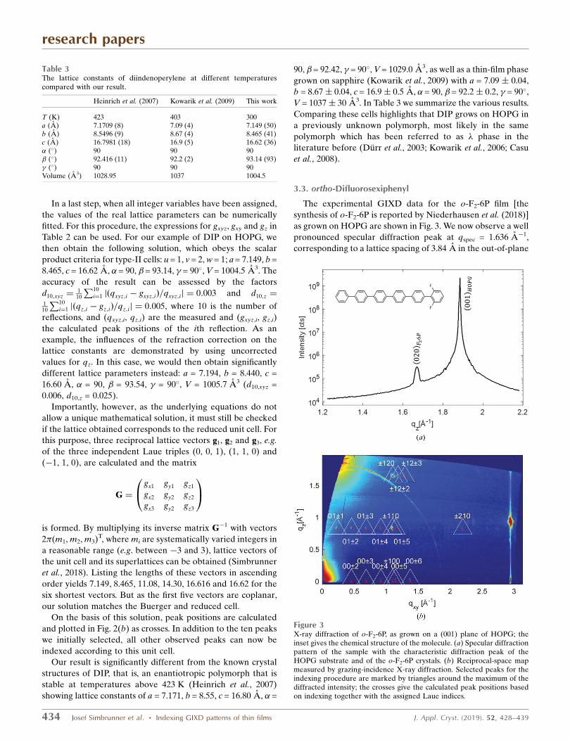
The experimental GIXD data for the o-F2-6P film [the
synthesis of o-F2-6P is reported by Niederhausen et al. (2018)]
as grown on HOPG are shown in Fig. 3. We now observe a well
pronounced specular diffraction peak at qspec = 1.636 A�1,
corresponding to a lattice spacing of 3.84 A in the out-of-plane
research papers
434 Josef Simbrunner et al. � Indexing GIXD patterns of thin films J. Appl. Cryst. (2019). 52, 428–439
Table 3The lattice constants of diindenoperylene at different temperaturescompared with our result.
Heinrich et al. (2007) Kowarik et al. (2009) This work
T (K) 423 403 300a (A) 7.1709 (8) 7.09 (4) 7.149 (50)b (A) 8.5496 (9) 8.67 (4) 8.465 (41)c (A) 16.7981 (18) 16.9 (5) 16.62 (36)� (�) 90 90 90� (�) 92.416 (11) 92.2 (2) 93.14 (93)� (�) 90 90 90Volume (A3) 1028.95 1037 1004.5
Figure 3X-ray diffraction of o-F2-6P, as grown on a (001) plane of HOPG; theinset gives the chemical structure of the molecule. (a) Specular diffractionpattern of the sample with the characteristic diffraction peak of theHOPG substrate and of the o-F2-6P crystals. (b) Reciprocal-space mapmeasured by grazing-incidence X-ray diffraction. Selected peaks for theindexing procedure are marked by triangles around the maximum of thediffracted intensity; the crosses give the calculated peak positions basedon indexing together with the assigned Laue indices.

direction. Like the case of DIP above, this points to lying �-
stacked growth of the molecules on the HOPG substrate, a
growth behaviour that has been reported before for related
systems (Salzmann et al., 2012). The reciprocal-space map
reveals, besides the diffraction peaks of HOPG (see discussion
above), a highly regular sequence of Bragg peaks located at
constant qz values. In this example, the indexing procedure
was performed on 16 selected reflections.
In marked contrast to non-substituted 6P growing in a
monoclinic crystal structure (Baker et al., 1993; Resel, 2003),
from the highly symmetric diffraction pattern, an ortho-
rhombic lattice with its contact plane parallel to the (010)
plane (u = w = 0) can be assumed for o-F2-6P on HOPG. As for
the specular scan the relation gspec ¼ 2ð2�=bÞ (v = 2) holds, the
following expressions (see Table 2) follow:
g2xy ¼ g2
x þ g2y ¼ h2 2�=að Þ
2þ l2 2�=cð Þ
2; ð19Þ
gz ¼ k2�=b: ð20Þ
On that basis, we obtained for the unit cell of o-F2-6P on
HOPG: u = 0, v = 2, w = 0; a = 5.724, b = 7.659, c = 27.424 A, �=
� = � = 90�, V = 1202.3 A3. The accuracy of the result can be
assessed by d16;xyz ¼1
16
P16i¼1 jðqxyz;i � gxyz;iÞ=qxyz;ij ¼ 0:0015
and d10;z ¼1
10
P10i¼1 jðqz;i � gz;iÞ=qz;ij ¼ 0:0015, as for dN,z only
the 10 reflections with k > 0 are included. Note that as a result
of equation (24) the Laue indices h and l can be either positive
or negative. Again, if uncorrected values for qz were used, b =
7.614 A would follow. It can be proven that a, b and c are the
shortest non-coplanar unit-cell vectors.
As an illustration of the comparison between calculated
peaks and experimental data, the peak positions are plotted in
Fig. 3(b) as crosses; there are no crystal structures known so
far for molecular crystals of o-F2-6P. The low out-of-plane
lattice spacing that we observe via specular diffraction
strongly points to �-stacked growth of this fluorinated 6P
derivative, if grown on HOPG. This is remarkable insofar as
non-substituted 6P grows in a herringbone arrangement of the
molecules in all known structures and on numerous surfaces
including HOPG (Resel, 2003) and, therefore, it is obviously
the (one-sided) fluorination of the molecule that changes its
growth behaviour dramatically. A similar behaviour has been
observed for pentacene (herringbone) and perfluoro-
pentacene on HOPG (�-stacking) (Salzmann et al., 2012), as
well as for 6,13-bis(triisopropylsilylethynyl)pentacene and
pentacenequinone (Swartz et al., 2005). The transition from
inclined to parallel molecular planes in these structures has
been ascribed to the impact of intramolecular polar bonds by
the authors. For o-F2-6P, no bulk crystal structures have been
published yet, and structural characterization was limited to
sub-monolayers on Ag(111) by low-temperature scanning
tunnelling microscopy (Niederhausen et al., 2018). There, in
contrast to non-fluorinated 6P molecules which individually
adsorb in the sub-monolayer regime on the metal surface
without packing, the authors find a flat lying stack arrange-
ment of the o-F2-6P molecules with small lateral shifts along
the row direction. The net dipole moment of o-F2-6P is
derived as 1.1 Debye owing to the polar C—F bonds at the
ortho position of the outer phenyl ring, which appear to
maximize their distance in neighbouring molecules.
Building upon previous work (Salzmann et al., 2011; Truger
et al., 2016), the unit cell determined in the present work for
o-F2-6P (and, likewise, for DIP) can now be used to model the
molecular arrangement therein, which will be the subject of a
forthcoming study.
4. Discussion – determining the crystallographic system
In the case of powder diffraction only the lengths of the
reciprocal-space vectors are used for indexing. In the
dichotomy method the cell constants are varied in increasingly
smaller intervals and the hkl indices are subsequently refined
using the least-squares method (Boultif & Louer, 1991, 2004).
The search of indexing solutions typically starts from the cubic
end of the symmetry sequence. Each crystal system is explored
independently up to a maximum input volume, unless a
solution has been found with a higher symmetry.
Indexing of GIXD patterns is based on the knowledge of
two components of the reciprocal space vector, the in-plane
component qxy and the out-of-plane component qz [Fig. 1(a)].
Since the lattice type cannot be assigned a priori, we suggest
following an iterative approach. As a consequence of imper-
fect data due to experimental inaccuracies, it seems that
starting with a lattice of higher symmetry is favourable, since
incoherency becomes evident quickly and the tendency to find
only a ‘local minimum’ when finally optimizing the cell para-
meters increases with the number of variables in the equa-
tions. Moreover, boundary conditions and experimental
constraints can be included in the indexing procedure with less
numerical effort. If no satisfactory solution can be found with
a specific lattice type, the next lower symmetry system will
then be used.
In single-crystal diffraction, where reciprocal lattice vectors
are used for indexing, in a first step the model parameters are
refined in a triclinic setting. If possible symmetry elements are
detected, cell refinement with symmetry-bases restraints is
performed (Sauter et al., 2004). In the matrix approach to
symmetry (Himes & Mighell, 1987) this is accomplished by 64
symmetry matrices to check if the transformation leads to
identity. Furthermore, systems of higher symmetry imply a
high impact of symmetry considerations such as diffraction
intensities and systematic absences (Hahn, 2006). Determi-
nation of the symmetry profile in crystallographic structures is
a persistent challenge (Hicks et al., 2018) and certainly lies
beyond the scope of the present work.
The final goal in crystallographic analysis is the determi-
nation of the most fundamental property of the structure – the
correct space group. Four steps are necessary to achieve this
endeavour (Marsh, 1995): (i) the derivation of the correct
space lattice, i.e. the smallest primitive (reduced) unit cell; (ii)
the assignment of the correct Laue group on the basis of the
symmetry of the diffraction intensities and an initial decision
if a structure is centrosymmetric; (iii) the identification of
any systematic absences characteristic of translational
symmetry elements (glide planes or screw axes); and (iv) the
research papers
J. Appl. Cryst. (2019). 52, 428–439 Josef Simbrunner et al. � Indexing GIXD patterns of thin films 435

final decision as to whether or not the structure is centro-
symmetric. Higher metric symmetry is usually identified by
computer programs (Hicks et al., 2018).
We emphasize that in the present work we focus only on the
first point. For determining the lattice parameters and
indexing of the diffraction pattern it is appropriate to choose
the crystallographic system of the highest order which can be
rationally fitted to the measured reflections. However, it is not
the shape of the unit cell that determines the lattice type but
the symmetry of the diffraction intensities (Marsh, 1995).
In GIXD the diffraction intensities are influenced by
various parameters. This may impede the determination of the
correct Laue group. Furthermore, as the in-plane component
of the reflections is measured, the Laue indices in lattices of
higher symmetry can be ‘degenerate’, i.e. they cannot be
assigned with positive or negative sign, as is the case in our
example of o-F2-6P. For the reliable identification of
systematic absences it is further necessary to obtain a
reasonable number of reflections.
5. Conclusion
Indexing of GIXD data of fibre-textured films is important for
phase analysis as well as for the identification of new poly-
morphs. In the present work, we provide a unifying framework
for indexing reciprocal-space maps obtained by GIXD for
monoclinic lattices and lattices of higher symmetry. Our
approach of including the Bragg peak from a specular X-ray
diffraction experiment into the mathematical formalism is of
considerable help for indexing of GIXD patterns, where the
spatial orientation of the unit cell must be considered. Math-
ematical expressions with a significantly reduced number of
unit-cell parameters are derived, which facilitates the
computational efforts. For crystallographic lattices of higher
symmetry, where the set of unit-cell parameters is reduced, the
specular diffraction peak is still important for determining the
orientation of the crystallographic unit cell relative to the
sample surface. Procedures are described in detail for how to
use the derived mathematical expressions. We demonstrate
the high value of our approach by successfully applying our
formalism for indexing diffraction patterns of two organic
semiconductors grown as crystalline thin films on graphite
surfaces. We find a monoclinic lattice for diindenoperylene
and an orthorhombic lattice for ortho-difluorosexiphenyl, the
unit-cell parameters of which were successfully determined
following our approach.
APPENDIX AAlternative rotation parameters if no contact planeexists
If u, v and w have to be assumed to be non-integers, it may be
preferable to replace the vector guvw by a sample surface
normal vector n = (sin sin�, �cos sin�, cos�)T with the
rotation angles � and . Then for the monoclinic system the
following expression can be derived:
g2xyz ¼ h2 2�=að Þ
2þ k2 2�=bð Þ
2
þgz � sin � hð2�=aÞ sin � kð2�=bÞ cos ½
cos�
� �2
: ð21Þ
The same equation is valid in the orthorhombic case.
For the tetragonal and cubic systems the following expres-
sion is valid:
g2xyz ¼ h2
þ k2� �
2�=að Þ2
þgz � ð2�=aÞ sin � h sin � k cos ð Þ
cos �
�2
: ð22Þ
Therefore, especially in the cubic case, it is much easier to
solve the equation
g2xyz ¼ h2
þ k2þ l2
� �2�=að Þ
2ð23Þ
first, as in the case of powder diffraction, and then to deter-
mine the rotation parameters.
Note that for DIP � = 76.11� and = 149.37�. In the case of
o-F2-6P � = 90� and = 180�.
APPENDIX BMathematical expressions for tetragonal, trigonal andhexagonal systems
In Table 4 we summarize the mathematical expressions for
gxyz, gz, gxy and the volume V in trigonal and hexagonal
systems.
From equation (11), the following formulae for 2�=a in
tetragonal and hexagonal systems, respectively, can be
derived:
Tetragonal:
With p ¼ hv� ku and P ¼ ðh2 þ k2Þg2spec � 2ðhuþ kvÞ �
gspecgz þ ðu2 þ v2Þg2
xyz
if p 6¼ 0:2�
a
2
¼P� ðP2 � 4p2g2
xyg2specÞ
1=2
2p2ð24Þ
if p ¼ 0:2�
a¼
gxygspec
P1=2ð25Þ
Hexagonal:
With p ¼ hv� ku and P ¼ ðh2 þ hkþ k2Þg2spec � ð2hu þ
2kvþ hvþ kuÞgspecgz þ ðu2 þ uvþ v2Þg2
xyz
if p 6¼ 0:2�
a
2
¼P� ðP2 � 3p2g2
xyg2specÞ
1=2
2p2ð26Þ
if p ¼ 0:2�
a¼
31=2
2
gxygspec
P1=2ð27Þ
In both cases, by systematically varying the integer variables u,
v, h and k, the factor 2�/a must be constantly observed for
every reflection, allowing the assessment of the appropriate
Miller and Laue indices.
research papers
436 Josef Simbrunner et al. � Indexing GIXD patterns of thin films J. Appl. Cryst. (2019). 52, 428–439
APPENDIX CCalculating a and b from two pairs of (gxy, gz) in amonoclinic lattice
If (gxy,1, gz,1) and (gxy,2, gz,2) are the components of two Bragg
peaks with the corresponding Laue indices (h1, k1) and (h2,
k2), respectively, as a result of equation (14) the following
relations arise:
2�
a
2
g2h;1 þ
u2
g2spec
!þ
2�
b
2
g2k;1 þ
v2
g2spec
!
�2�
a
22�
b
2h1v� k1uð Þ
2
g2xy;1g2
spec
¼ 1; ð28Þ
2�
a
2
g2h;2 þ
u2
g2spec
!þ
2�
b
2
g2k;2 þ
v2
g2spec
!
�2�
a
22�
b
2h2v� k2uð Þ
2
g2xy;2g2
spec
¼ 1; ð29Þ
where gh;1 ¼ ð1=gxy;1Þðh1 � ugz;1=gspecÞ, gh;2 ¼ ð1=gxy;2Þ �
ðh2 � ugz;2=gspecÞ, gk;1 ¼ ð1=gxy;1Þðk1 � vgz;1=gspecÞ and gk;2 ¼
ð1=gxy;2Þðk2 � vgz;2=gspecÞ. Expressing ð2�=bÞ2 in equation (28)
as a function of ð2�=aÞ2 and substituting this term in equation
(29) leads to a quadratic equation for ð2�=aÞ2, which has the
two solutions
2�=að Þ2¼ 2 g2
k;2 � g2k;1
� ���g2
h;1g2k;2 � g2
h;2g2k;1
� �þ ð2uv=g2
specÞ gh;1gk;1 � gh;2gk;2
� �þ 2ðu2=g2
specÞ g2k;2 � g2
k;1
� �� �
�; ð30Þ
where
� ¼ gh;1gk;2 � gh;2gk;1
�� ��� gh;1gk;2 þ gh;2gk;1 � 2uv=g2
spec
� �2h
þ2ðuv=g2specÞ gh;1 þ gh;2
� �gk;1 þ gk;2
� ��1=2: ð31Þ
Consequently,
2�=bð Þ2¼ 2 g2
h;2 � g2h;1
� ���g2
k;1g2h;2 � g2
h;1g2k;2
� �þ 2ðuv=g2
specÞ gh;1gk;1 � gh;2gk;2
� �þ 2ðv2=g2
specÞ g2h;2 � g2
h;1
� � �
�: ð32Þ
APPENDIX DDetermining a and b from k1, k2 and k3
From �1, �2 and �3 the tentative cell parameters at = 2��1�1/2,
bt = 2��2�1/2 and their product (ab)t = (2�)2�3
�1/2 can be
determined. An optimal solution for a and b can be obtained
by minimizing the following function F:
Fða; bÞ ¼ 1�at
a
� �2
þ 1�bt
b
2
þ 1�ðabÞt
ab
�2
: ð33Þ
research papers
J. Appl. Cryst. (2019). 52, 428–439 Josef Simbrunner et al. � Indexing GIXD patterns of thin films 437
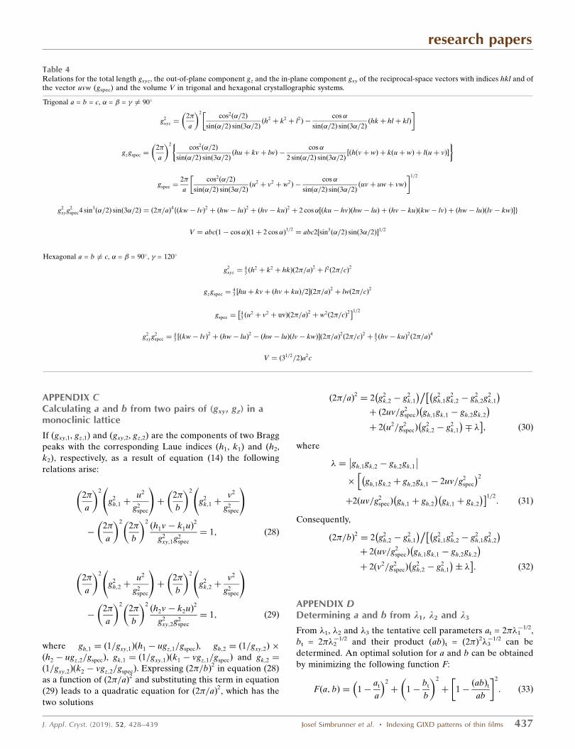
Table 4Relations for the total length gxyz, the out-of-plane component gz and the in-plane component gxy of the reciprocal-space vectors with indices hkl and ofthe vector uvw (gspec) and the volume V in trigonal and hexagonal crystallographic systems.
Trigonal a = b = c, � = � = � 6¼ 90�
g2xyz ¼
2�
a
2cos2ð�=2Þ
sinð�=2Þ sinð3�=2Þðh2þ k2þ l2Þ �
cos�
sinð�=2Þ sinð3�=2Þðhkþ hl þ klÞ
�
gzgspec ¼2�
a
2cos2ð�=2Þ
sinð�=2Þ sinð3�=2Þðhuþ kvþ lwÞ �
cos�
2 sinð�=2Þ sinð3�=2Þ½ðhðvþ wÞ þ kðuþ wÞ þ lðuþ vÞ
� �
gspec ¼2�
a
cos2ð�=2Þ
sinð�=2Þ sinð3�=2Þðu2þ v2þ w2Þ �
cos�
sinð�=2Þ sinð3�=2Þðuvþ uwþ vwÞ
�1=2
g2xyg2
spec4 sin3ð�=2Þ sinð3�=2Þ ¼ ð2�=aÞ4fðkw� lvÞ2 þ ðhw� luÞ2 þ ðhv� kuÞ2 þ 2 cos�½ðku� hvÞðhw� luÞ þ ðhv� kuÞðkw� lvÞ þ ðhw� luÞðlv� kwÞg
V ¼ abcð1� cos�Þð1þ 2 cos�Þ1=2¼ abc2½sin3
ð�=2Þ sinð3�=2Þ1=2
Hexagonal a = b 6¼ c, � = � = 90�, � = 120�
g2xyz ¼
43 ðh
2 þ k2 þ hkÞ 2�=að Þ2þ l2 2�=cð Þ
2
gzgspec ¼43 huþ kvþ ðhvþ kuÞ=2½ 2�=að Þ
2þ lw 2�=cð Þ
2
gspec ¼43 ðu
2 þ v2 þ uvÞ 2�=að Þ2þ w2 2�=cð Þ
2� �1=2
g2xyg2
spec ¼43 ½ðkw� lvÞ2 þ ðhw� luÞ2 � ðhw� luÞðlv� kwÞ 2�=að Þ
2 2�=cð Þ2þ 4
3 ðhv� kuÞ2 2�=að Þ4
V ¼ ð31=2=2Þa2c
This can be achieved if @F=@a ¼ 0 and @F=@b ¼ 0 are
fulfilled. Then the following solution can be obtained:
a ¼qþD
2þ ðqDÞ
1=2
�1=3
þqþD
2� ðqDÞ
1=2
�1=3
; ð34Þ
b ¼ abt=at; ð35Þ
where q ¼ atðabÞ2t =ð2b2t Þ and D ¼ q þ 2f½ðabÞt � atbt=ð3btÞg
3.
APPENDIX EMathematical procedure for analytically determiningthe cell parameters a, c and b
For analytically determining the unit-cell parameters a, c and �from equation (17) it is convenient to introduce the para-
meters Xa, Xc and X� with the substitutional relations
Xa ¼2�
a sin �
2
1�2�
c
2w2
g2spec
" #; ð36Þ
Xc ¼2�
c sin �
2
1�2�
a
2u2
g2spec
" #; ð37Þ
X� ¼2�
a sin �
2�
c sin �cos��
2�
a
2�
c
uw
g2spec
!: ð38Þ
Using these substitutions, equation (17) can be rewritten as
Xa
1
g2xy
h� ugz
gspec
!2
þu2
g2spec
" #
þ Xc
1
g2xy
l � wgz
gspec
!2
þw2
g2spec
" #
� 2X�
1
g2xy
h� ugz
gspec
!l � w
gz
gspec
!þ
uw
g2spec
" #¼ 1: ð39Þ
Then from three independent Bragg peak series, the para-
meters Xa, Xc and X� can be determined using a system of
linear equations. For obtaining a, c and � from equations (36)–
(38) the following identity is helpful:
2�
a sin �
22�
c
21
g2spec
¼XaXc � X2
�
g2spec � u2Xa þ w2Xc � 2uwX�
� � :ð40Þ
Acknowledgements
We thank W. Caliebe (HASYLAB, DESY) for experimental
support.
Funding information
IS acknowledges the support of the Natural Sciences and
Engineering Research Council of Canada (NSERC) [funding
reference number RGPIN-2018-05092] and Concordia
University. Generous support by the German Research
Foundation (DFG via SFB 951) is gratefully acknowledged.
Funding from the Austrian Science Fund (grant No. P30222) is
also acknowledged.
References
Baker, K. N., Fratini, A. V., Resch, T., Knachel, H. C., Adams, W. W.,Socci, E. P. & Farmer, B. L. (1993). Polymer, 34, 1571–1587.
Boultif, A. & Louer, D. (1991). J. Appl. Cryst. 24, 987–993.Boultif, A. & Louer, D. (2004). J. Appl. Cryst. 37, 724–731.Bronshtein, I. N., Semendyayev, K. A., Musiol, G. & Muhlig, H.
(2015). Handbook of Mathematics, 6th ed. Berlin: Springer.Buerger, M. J. (1957). Z. Kristallogr. 109, 42–60.Casu, M. B., Biswas, I., Nagel, M., Nagel, P., Schuppler, S. & Chasse, T.
(2008). Phys. Rev. B, 78, 075310.De Wolff, P. M. (2016). International Tables for Crystallography,
Vol. A, Space-Group Symmetry, 6th ed., pp. 709–713. Chichester:Wiley.
Djuric, T., Ules, T., Gusenleitner, S., Kayunkid, N., Plank, H.,Hlawacek, G., Teichert, C., Brinkmann, M., Ramsey, M. & Resel, R.(2012). Phys. Chem. Chem. Phys. 14, 262–272.
Durr, A. C., Koch, N., Kelsch, M., Ruhm, A., Ghijsen, J., Johnson,R. L., Pireaux, J. J., Schwartz, J., Schreiber, F., Dosch, H. & Kahn,A. (2003). Phys. Rev. B, 68, 115428.
Giacovazzo, C. (2011). Editor. Fundamentals of Crystallography, 3rded. Oxford University Press.
Hahn, Th. (2006). Editor. International Tables for Crystallography,Vol. A, Space-Group Symmetry, 1st online ed. Chester: Interna-tional Union of Crystallography.
Hailey, A. K., Hiszpanski, A. M., Smilgies, D.-M. & Loo, Y.-L. (2014).J. Appl. Cryst. 47, 2090–2099.
Heinrich, M. A., Pflaum, J., Tripathi, A. K., Frey, W., Steigerwald,M. L. & Siegrist, T. (2007). J. Phys. Chem. C, 111, 18878–18881.
Hicks, D., Oses, C., Gossett, E., Gomez, G., Taylor, R. H., Toher, C.,Mehl, M. J., Levy, O. & Curtarolo, S. (2018). Acta Cryst. A74, 184–203.
Himes, V. L. & Mighell, A. D. (1987). Acta Cryst. A43, 375–384.Jiang, Z. (2015). J. Appl. Cryst. 48, 917–926.Kowarik, S., Gerlach, A., Sellner, S., Cavalcanti, L., Konovalov, O. &
Schreiber, F. (2009). Appl. Phys. A, 95, 233–239.Kowarik, S., Gerlach, A., Sellner, S., Schreiber, F., Cavalcanti, L. &
Konovalov, O. (2006). Phys. Rev. Lett. 96, 125504.Marsh, R. E. (1995). Acta Cryst. B51, 897–907.Mighell, A. D. (2000). Powder Diffr. 15, 82–85.Moser, A. (2012). PhD thesis, University of Technology, Graz,
Austria.Niederhausen, J., Zhang, Y., Cheenicode Kabeer, F., Garmshausen,
Y., Schmidt, B. M., Li, Y., Braun, K. F., Hecht, S., Tkatchenko, A.,Koch, N. & Hla, S. W. (2018). J. Phys. Chem. C, 122, 18902–18911.
Niggli, P. (1928). Handbuch der Experimentalphysik, Vol. 7, Part 1.Leipzig: Akademische Verlagsgesellschaft.
Resel, R. (2003). Thin Solid Films, 433, 1–11.Resel, R., Bainschab, M., Pichler, A., Dingemans, T., Simbrunner, C.,
Stangl, J. & Salzmann, I. (2016). J. Synchrotron Rad. 23, 729–734.Salzmann, I., Moser, A., Oehzelt, M., Breuer, T., Feng, X., Juang,
Z. Y., Nabok, D., Della Valle, R. G., Duhm, S., Heimel, G., Brillante,A., Venuti, E., Bilotti, I., Christodoulou, C., Frisch, J., Puschnig, P.,Draxl, C., Witte, G., Mullen, K. & Koch, N. (2012). ACS Nano, 6,10874–10883.
Salzmann, I., Nabok, D., Oehzelt, M., Duhm, S., Moser, A., Heimel,G., Puschnig, P., Ambrosch-Draxl, C., Rabe, J. P. & Koch, N. (2011).Cryst. Growth Des. 11, 600–606.
Salzmann, I. & Resel, R. (2004). J. Appl. Cryst. 37, 1029–1033.Santoro, A. & Mighell, A. D. (1970). Acta Cryst. A26, 124–127.Santoro, A., Mighell, A. D. & Rodgers, J. R. (1980). Acta Cryst. A36,
796–800.
research papers
438 Josef Simbrunner et al. � Indexing GIXD patterns of thin films J. Appl. Cryst. (2019). 52, 428–439

Sauter, N. K., Grosse-Kunstleve, R. W. & Adams, P. D. (2004). J. Appl.Cryst. 37, 399–409.
Shmueli, U. (2006). Editor. International Tables for Crystallography,Vol. B, Reciprocal Space, 1st online ed. Chester: InternationalUnion of Crystallography.
Simbrunner, J., Simbrunner, C., Schrode, B., Rothel, C., Bedoya-Martinez, N., Salzmann, I. & Resel, R. (2018). Acta Cryst. A74,373–387.
Smilgies, D.-M. & Blasini, D. R. (2007). J. Appl. Cryst. 40, 716–718.
Swartz, C. R., Parkin, S. R., Bullock, J. E., Anthony, J. E., Mayer, A. C.& Malliaras, G. G. (2005). Org. Lett. 7, 3163–3166.
Truger, M., Roscioni, O. M., Rothel, C., Kriegner, D., Simbrunner, C.,Ahmed, R., Głowacki, E. D., Simbrunner, J., Salzmann, I., Coclite,A. M., Jones, A. O. F. & Resel, R. (2016). Cryst. Growth Des. 16,3647–3655.
research papers
J. Appl. Cryst. (2019). 52, 428–439 Josef Simbrunner et al. � Indexing GIXD patterns of thin films 439