INDEXES—Table of Contents HD-01 - transportation.ky.gov · Chapter 2 of AASHTO’s A Policy on...
47
INDEXES—Table of Contents HD-01 900 INTERSECTIONS 901 General Design Considerations & Objectives 901.1 Overview................................................................................................... 09/16 901.2 Human Factors ......................................................................................... 09/16 901.3 Traffic Considerations............................................................................... 09/16 901.4 Physical Elements ..................................................................................... 09/16 901.5 Economic Factors ..................................................................................... 09/16 901.6 Intersection Approval ............................................................................... 09/16 902 At-Grade Intersections 902.1 Overview................................................................................................... 09/16 902.2 Horizontal and Vertical Alignment ........................................................... 09/16 902.3 Turning Roadway Elements ...................................................................... 09/16 902.4 Roundabouts ............................................................................................ 09/16 902.5 Islands and Channelization ....................................................................... 09/16 902.6 Superelevation ......................................................................................... 09/16 902.7 Traffic Control Devices ............................................................................. 09/16 902.8 Intersection Sight Distance....................................................................... 09/16 902.9 Median Openings (Crossovers) ................................................................ 09/16 902.10 Auxiliary Lanes .......................................................................................... 09/16 902.11 Left Turn Lanes ......................................................................................... 09/16 902.11.1 Signalized Intersections .......................................................... 09/16 902.11.2 Unsignalized Intersections ..................................................... 09/16 902.11.3 Left Turn Evaluations ............................................................. 09/16 902.12 Right Turn Lanes ....................................................................................... 09/16 902.12.1 Signalized Intersections .......................................................... 09/16 902.12.2 Unsignalized Intersections ..................................................... 09/16 902.13 Turn Lane Design ...................................................................................... 09/16 902.14 Departure/Approach Taper ...................................................................... 09/16 902.15 Bay Taper .................................................................................................. 09/16 902.16 Turn Lane Length ...................................................................................... 09/16 902.17 Storage Length.......................................................................................... 09/16 902.18 Alternative Turn Lane Designs.................................................................. 09/16 902.19 Positive Offset of Turn Lanes.................................................................... 09/16 902.20 Two-Way Left-Turn Lanes......................................................................... 09/16 902.21 Driveways and Entrances ......................................................................... 09/16 902.22 Pedestrian and Bicycles ............................................................................ 09/16 903 Grade Separation without Ramps 903.1 Overview................................................................................................... 09/16 903.2 Vertical Clearance..................................................................................... 09/16 903.3 Horizontal Clearance ................................................................................ 09/16 904 Interchanges 904.1 Definition .................................................................................................. 09/16 904.2 Design Considerations .............................................................................. 09/16
-
Upload
nguyenhanh -
Category
Documents
-
view
216 -
download
0
Transcript of INDEXES—Table of Contents HD-01 - transportation.ky.gov · Chapter 2 of AASHTO’s A Policy on...
INDEXES—Table of Contents HD-01
900 INTERSECTIONS 901 General Design Considerations & Objectives 901.1 Overview ................................................................................................... 09/16 901.2 Human Factors ......................................................................................... 09/16
901.3 Traffic Considerations............................................................................... 09/16 901.4 Physical Elements ..................................................................................... 09/16 901.5 Economic Factors ..................................................................................... 09/16
901.6 Intersection Approval ............................................................................... 09/16 902 At-Grade Intersections 902.1 Overview ................................................................................................... 09/16 902.2 Horizontal and Vertical Alignment ........................................................... 09/16
902.3 Turning Roadway Elements ...................................................................... 09/16 902.4 Roundabouts ............................................................................................ 09/16 902.5 Islands and Channelization ....................................................................... 09/16
902.6 Superelevation ......................................................................................... 09/16 902.7 Traffic Control Devices ............................................................................. 09/16 902.8 Intersection Sight Distance ....................................................................... 09/16
902.9 Median Openings (Crossovers) ................................................................ 09/16 902.10 Auxiliary Lanes .......................................................................................... 09/16 902.11 Left Turn Lanes ......................................................................................... 09/16 902.11.1 Signalized Intersections .......................................................... 09/16
902.11.2 Unsignalized Intersections ..................................................... 09/16 902.11.3 Left Turn Evaluations ............................................................. 09/16 902.12 Right Turn Lanes ....................................................................................... 09/16 902.12.1 Signalized Intersections .......................................................... 09/16
902.12.2 Unsignalized Intersections ..................................................... 09/16 902.13 Turn Lane Design ...................................................................................... 09/16 902.14 Departure/Approach Taper ...................................................................... 09/16
902.15 Bay Taper .................................................................................................. 09/16 902.16 Turn Lane Length ...................................................................................... 09/16
902.17 Storage Length.......................................................................................... 09/16 902.18 Alternative Turn Lane Designs.................................................................. 09/16 902.19 Positive Offset of Turn Lanes .................................................................... 09/16
902.20 Two-Way Left-Turn Lanes......................................................................... 09/16 902.21 Driveways and Entrances ......................................................................... 09/16 902.22 Pedestrian and Bicycles ............................................................................ 09/16 903 Grade Separation without Ramps 903.1 Overview ................................................................................................... 09/16 903.2 Vertical Clearance ..................................................................................... 09/16 903.3 Horizontal Clearance ................................................................................ 09/16 904 Interchanges 904.1 Definition .................................................................................................. 09/16 904.2 Design Considerations .............................................................................. 09/16

INDEXES—Table of Contents HD-01
904.3 Horizontal and Vertical Alignment ........................................................... 09/16 904.4 Ramps ....................................................................................................... 09/16 904.5 Ramp Terminals ........................................................................................ 09/16 904.6 Superelevation ......................................................................................... 09/16 904.7 Speed-Change Lanes ................................................................................ 09/16 904.8 Geometric Layout Sheet (GLS) ................................................................. 09/16

Highway Design Manual
Chapter
EXHIBITS
Subject
Table of Exhibits
900-01 Pavement Development Sheet 900-02 Basic Geometric Elements of a Roundabout 900-03 Example: Cross Road Profile Adjustment 900-04 Common Practice for Ramp Tapers 900-05 Typical Sections: One Lane Ramps 900-06 Typical Sections: Two Lane Ramps 900-07 Common Practices for Ramp Terminals at Crossroads (Rural) 900-08 Common Practices for Ramp Terminals at Crossroads (Urban) 900-09 Geometric Layout Sheet

HD-901
09/16 Page 1 of 3
HIGHWAY DESIGN
Chapter
INTERSECTIONS
Subject
General Design Considerations & Objectives
HD-901.1 OVERVIEW
By definition, an intersection is the area in which two or more highways join or cross. This includes the roadway and the appurtenances associated with the intersecting roadways. Intersection design is a key component in the design of a highway system and affects the efficiency, safety, speed, operating costs, and capacity of the roadway system.
The three general types of intersections are:
At-grade intersections Grade separations without ramps Interchanges
The main goal of intersection design is to facilitate the safety, convenience, ease, and comfort of motorists, bicyclists, and pedestrians utilizing the intersection. Four basic elements should be considered in intersection design:
Human factors Traffic movement considerations Physical elements Economic factors
HD-901.2 HUMAN FACTORS
Human factors affecting intersection design include:
Driving habits The driver’s ability to make decisions Driver expectancy Decision and reaction time

INTERSECTIONS
General Design Considerations & Objectives HD-901
09/16 Page 2 of 3
Conformance to natural paths of movement Pedestrian use and habits Bicycle traffic use and habits
HD-901.3 TRAFFIC CONSIDERATIONS
Traffic issues to consider include:
Classification of each intersecting roadway Design and capacities Design-hour turning movements Size and operating characteristics of vehicle Variety of movements Vehicle speeds Transit Involvement Crash experience Pedestrian and bicycle movements
HD-901.4 PHYSICAL ELEMENTS
Several physical elements also affect intersection design. Important issues are:
Character and use of the adjoining property Vertical alignments of the intersecting roadways Sight distance Angle of the intersection Conflict area Speed-change lanes Geometric design features Traffic control devices Lighting equipment Roadside design features Environmental factors Crosswalks Driveways Access management treatments
HD-901.5 ECONOMIC FACTORS
The costs of intersection improvements should be considered as well as the effects of controlling or limiting rights of way on adjoining commercial and residential properties where channelization restricts or prohibits vehicular movements and energy consumption.

INTERSECTIONS
General Design Considerations & Objectives HD-901
09/16 Page 3 of 3
HD-901.6 INTERSECTION APPROVAL
As referenced in HD-204.7, intersections approvals should be completed during or immediately after approval of the Design Executive Summary. These are typically done for intersections that are deemed unconventional or complex. Refer to HD-902 for submittal of conceptual report and approval process for roundabouts and HD-904 for submittal of Geometric Layout Sheets (GLS) and approval for interchanges.
For other unconventional or complex intersections submit to project team:
Plan and profile details of the intersection roadways Traffic analysis Cost Estimates Discussion of the pros and cons of each alternative Other information the team believes to be beneficial
If recommended, submit to the Director of Highway Design for review and/or approval.

HD-902
09/16 Page 1 of 24
HIGHWAY DESIGN
Chapter
INTERSECTIONS
Subject
At-Grade Intersections
HD-902.1 OVERVIEW
The basic types of at-grade intersections are three-leg (T), four-leg, multi-leg, and roundabouts. At a minimum, the following should be considered at each intersection: Number of intersecting legs Topography of the area Character of the intersecting highways Traffic volumes and movements Speeds Desired type of operation The following design elements are critical to the layout and operation of at-grade intersections: Horizontal and vertical alignment Cross-sectional elements Sight distance Drainage issues
HD-902.2 HORIZONTAL AND VERTICAL ALIGNMENT
The horizontal alignment and vertical grades of an intersection should be designed to permit users to visually recognize the intersection and the other vehicles using it, and to readily perform the needed maneuvers to pass through the intersection safely.
Generally, the alignments should be as straight and the gradients as flat as practical. Major grade changes should be avoided at intersections, and adequate

INTERSECTIONS
At-Grade Intersections HD-902
09/16 Page 2 of 24
sight distance should be provided along both intersecting roads. Ideally, grades exceeding 3 percent in the vicinity of the intersection should be avoided. Where this is not practical, 6 percent grades should not be exceeded without adequate justification. Each intersection should be reviewed thoroughly and appropriate solutions identified. In the design of an intersection, the main line grades/cross-slopes generally are carried through the intersection, and the approach roadways are adjusted to match the main line geometrics. It is preferred that major intersections be developed as a site design allowing for smooth and continuous traffic movements through the intersection. The design may need to address intersection characteristics, such as: Traffic volumes Type of design vehicles Design speed Functional characteristics Type of intersection control Topographic constraints As necessary, each intersection is to be adjusted at all intersecting legs to accommodate adequate sight distance requirements, driver comfort during maneuvers, and drainage concerns. This adjustment might be accomplished by modification of the main line/approach grade points, cross-slopes, etc. The goals for an intersection include: Smooth and continuous intersection elements Smooth transitions for vehicles changing directions Grades as level as practical Sufficient sight distance to allow drivers to prepare for and avoid potential
conflicts For safety and economic reasons, the intersecting roadways should meet at right angles when feasible. Although a 90-degree intersection is desired, some deviation from this is permissible. Generally, intersection angles between 75 and 90 degrees are preferred. Intersection angles should not be less than 60 degrees. Change from one cross slope to another should be gradual. Intersections where a minor road crosses a multilane divided highway with a narrow median on a

INTERSECTIONS
At-Grade Intersections HD-902
09/16 Page 3 of 24
superelevated curve should be avoided whenever practical because of the difficulty in adjusting grades to provide a suitable crossing. The use of Pavement Development Sheets may be helpful in detailing the pavement transitions through the interchange (Exhibit 900-01).
HD-902.3 TURNING ROADWAY ELEMENTS
Turning roadways are typically used at high-speed and/or high-volume intersections, including intersections at ramp terminals (HD-904). It is important to provide a turning roadway design that is consistent with the speed and volume characteristics of the turning vehicles. The primary design elements of a turning roadway are as follows:
Radius of turn Development of superelevation Width of roadway
The relationships between speed and curvature may be found in Chapter 3 of AASHTO’s A Policy on Geometric Design of Highways and Streets. Kentucky’s common practice is to use a maximum superelevation of 8 percent. Special care should be taken with superelevation in transitions for turning roadways (See AASHTO’s A Policy on Geometric Design of Highways and Streets).
Three-centered, compound curves may also be considered when determining an intersection radius. Three-centered, compound curve information is available in the exhibit “Typical Designs for Turning Roadways” in Chapter 9 of AASHTO’s A Policy on Geometric Design of Highways and Streets.
The turning path of the design vehicle and the angle of turn determine the widths of turning roadways. Chapter 2 of AASHTO’s A Policy on Geometric Design of Highways and Streets details the various types of design vehicles with their dimensions and turning radii. Chapter 9 of the policy summarizes the values for various design vehicles and turning angles.
HD-902.4 ROUNDABOUTS
Modern roundabouts are an alternative to traffic signals and multi-way stop control intersections. To ensure successful operation, roundabouts must be placed appropriately and be designed properly for conditions. (See AASHTO’s A

INTERSECTIONS
At-Grade Intersections HD-902
09/16 Page 4 of 24
Policy on Geometric Design of Highways and Streets and NCHRP Report 672 Roundabouts: An Informational Guide). Roundabouts operate with the lowest crash frequencies when their geometry forces traffic to enter and circulate at slow speeds.
For a roundabout to be identified as a viable alternative, the Project Development Manager (PDM) shall submit a conceptual report to the Division of Highway Design through the Location Engineer for approval by the Director. This submittal should occur prior to public involvement activities that depict the roundabout, and no later than the preliminary line and grade meeting. This report shall include at a minimum:
Operational analysis Volume to capacity (V/C) ratio of each lane Delay by lane, approach and intersection Lane group queue estimates
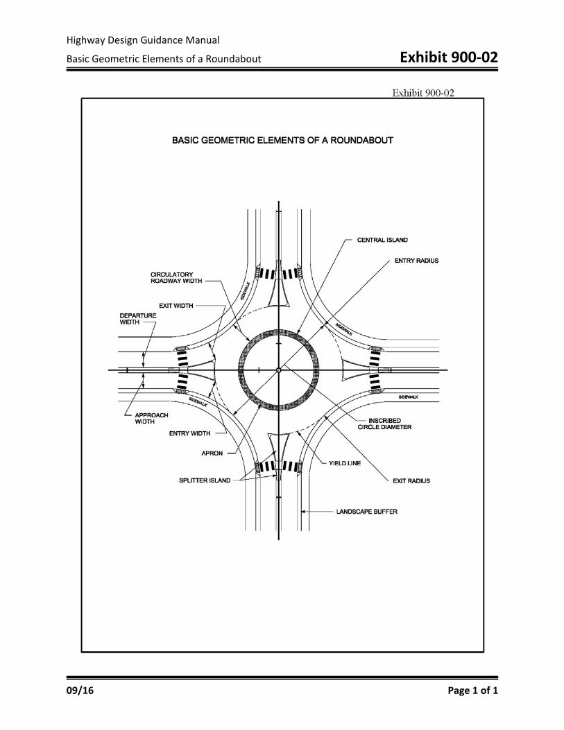
Lane configuration The design vehicle Primary layout, including inscribed circle diameter and other basic elements
(Exhibit 900-02)
The following information shall be submitted with the Intersection Approval Sheet (IAS) in a roundabout report:
Vehicle turning path Fastest path Entry angles Sight distances
Lighting, signing, and pavement markings shall be presented at the final inspection. Final plans shall include a plan view with base/centerlines for each approach and pavement development sheets sufficient to depict the entire roundabout.
HD-902.5 ISLANDS AND CHANNELIZATION
An island is the area between traffic lanes that is used to: Control the vehicle movements (channelization/division of traffic) Provide a pedestrian refuge area and a place for traffic control devices

INTERSECTIONS
At-Grade Intersections HD-902
09/16 Page 5 of 24
Contribute to aesthetics Within an intersection, a median is also considered an island.
Channelizing islands are used at certain intersections to control and direct traffic movements into the proper paths. If an intersection area is spacious, a channelizing island may decrease the confusion of the traffic movements. Channelizing islands may be of many shapes and sizes. A common form is the corner triangular shape, which separates right-turning movements. Central islands may serve as a separation for turning vehicles to operate around. Divisional islands are often included on undivided highways at intersections to alert and regulate traffic through the intersection. They may also control the location of left-turning vehicles. Splitter islands are typically utilized for roundabout intersections to provide separation of the entering and exiting traffic on the approaches. Raised splitter islands are typically utilized. Refuge islands are predominantly utilized in urban areas to aid and protect pedestrians and bicyclists crossing a roadway. Generally, any of the types of islands mentioned above could also serve as a refuge island as long as Americans with Disabilities Act (ADA) criteria are met. The dimensions and details of an island depend on each intersection’s configuration, but should always be of significant size to command attention. Islands can be delineated or outlined by a variety of treatments, depending on the size, location, and function. Island design is also controlled by the type of facility (rural versus urban) in which the intersection is located. Flush islands should be used in intersections to accommodate the off-tracking of large vehicles. Exceptions may be made the island is large and may shield pedestrians, or where special signing or poles may be placed in the island. It may be decided to utilize a raised island in this case. If a raised island is used, it should be designed as a mountable island where practical. Interchanges represent special median channelization design considerations. An inherent problem of interchanges is the possibility of a vehicle entering one of the exit terminals from the crossroad and proceeding along the major highway in the wrong direction. For this reason, medians on the crossroad should be strongly

INTERSECTIONS
At-Grade Intersections HD-902
09/16 Page 6 of 24
considered to facilitate proper channelization. While this median can be painted, a depressed or raised median should be considered. Where practical, large islands should be depressed to avoid water and snow melt draining across the pavement. (See Chapter 9 of AASHTO’s Policy on Geometric Design of Highways and Streets and HD-702).
HD-902.6 SUPERELEVATION
Normally, the superelevation rates for the through roadway at an intersection should comply with the appropriate values obtained in Chapter 3 of AASHTO's A Policy on Geometric Design of Highways and Streets. The designer may elect to modify the superelevation rates through the intersection area to achieve an acceptable design. The designer should first consider: A vehicle’s ability to stop and accelerate during periods of ice and snow Right-of-way damages Grade on existing street approaches and entrances Drainage The desirable maximum superelevation for horizontal curves through intersections is 4 percent. Exhibit 900-03 shows a procedure to reduce the sharp breaks in the profile of roads crossing a roadway with a depressed median. It depicts how adjustment of the grade points on the roadway having the depressed median can reduce the severity of the breaks at the inside edges of pavement. The decision of whether to use this or a similar procedure should be made on an intersection-by-intersection basis. Superelevated areas adjacent to a through lane having a normal crown or a different superelevation result in a "cross-over line" between adjacent lanes which can cause a hazardous pitch or sway in a vehicle. (See Chapter 9 in AASHTO's A Policy on Geometric Design of Highways and Streets.) Breaks in approach grades traversing mainline cross-slopes should be minimized whenever practical. When introducing or removing superelevation, refer to Chapter 3 of AASHTO's A

INTERSECTIONS
At-Grade Intersections HD-902
09/16 Page 7 of 24
Policy on Geometric Design of Highways and Streets. HD-902.7 TRAFFIC CONTROL DEVICES
Traffic control devices regulate, inform, warn, and guide drivers. Such devices include signals, lighting, signing, arrow panels, and changeable message signs. The decision to utilize traffic control devices or lighting should be made on an intersection-by-intersection basis. The project manager is ultimately responsible for making sure the appropriate traffic plans are identified and included in the total plan set. To facilitate this process, the project manager should notify the District Traffic Engineer of project meetings and inspections as early in the process as feasible. When locations are identified that might require signal, signing, and/or lighting plans, notify the District Traffic Engineer and copy Central Office Traffic Operations. The District Traffic Engineer will send a written request and provide appropriate supporting information to Central Office Traffic Operations.
HD-902.8 INTERSECTION SIGHT DISTANCE
The driver of a vehicle approaching an intersection should have an unobstructed view of the entire intersection, including any traffic-control devices, and sufficient lengths along the intersecting highway to permit the driver to anticipate and avoid potential collisions. When determining whether an object or structure is obstructing sight distance at an intersection, the designer should consider both horizontal and vertical sight lines for both intersecting roadways. The designer assumes that the driver’s eye height is 3.5 feet above the roadway and that the object height is also 3.5 feet above the surface of the roadway. Using 3.5 feet for both the driver’s eye and the object height ensures that each driver can see the other’s vehicle. The minimum stopping sight distance at any point within an intersection shall be consistent with the speed at that point (see Common Geometric Practices, Chapter 700). The recommended dimensions of the sight triangles vary with the type of traffic control. Procedures to determine sight distances at intersections are presented in Chapter 9 of AASHTO's A Policy on Geometric Design of Highways and Streets.

INTERSECTIONS
At-Grade Intersections HD-902
09/16 Page 8 of 24
At intersections where cross traffic is controlled by a stop sign, additional stopping sight distance must be provided for the vehicles on the major highway due to the possibility of conflicts between vehicles on the through road and the cross road. The desired intersection sight distance is a function of the following:
Type of control Design vehicle Acceleration rate of design vehicle Perception and reaction time Width of pavement and, in cases of divided highways, width of median Design speeds Skew angle of intersection and gradient of roadways Gap acceptance
AASHTO's A Policy on Geometric Design of Highways and Streets contains a thorough discussion of intersection sight distance.
HD-902.9 MEDIAN OPENINGS (CROSSOVERS)
Median openings are breaks in the median to allow traffic to cross. These openings facilitate traffic movement and access management. Spacing of the openings should be consistent with the type of access control along the roadway. Median openings should be situated where there is adequate sight distance. The design of a median opening and the shape of the median ends should be based on traffic volumes, urban/rural characteristics, and types of turning vehicles. The median width; location and length of opening; and the design of the median-end shape, are developed in combination to fit the character and volume of both through and turning traffic. For three- or four-leg intersections on a divided highway, the length of median opening should be as great as the width of the crossroad, including shoulders and median. There are two common shapes utilized at the ends of a median: Semicircle, which is satisfactory for narrow medians
Bullet nose, which closely fits the path of the inner wheel of the design vehicle Note: Bullet nose is the preferred shape at approach intersections and should be used for median widths 10 feet or greater.

INTERSECTIONS
At-Grade Intersections HD-902
09/16 Page 9 of 24
Chapter 9 of AASHTO’s A Policy on Geometric Design of Highways and Streets provides specific details of median opening shapes.
HD-902.10 AUXILIARY LANES
An auxiliary lane is the section of the roadway adjacent to the through lanes that are utilized for: Speed changes Left- and right-turning movements Storage Weaving maneuvers Truck-climbing lanes Other various purposes Auxiliary lanes may also be added to improve the safety and the capacity of an intersection. Warrants for the use of auxiliary lanes cannot be stated definitely. Many factors should be considered such as speeds, traffic volumes, percentage of trucks, capacity, type of highway, availability of right-of-way, service provided, and the arrangement and frequency of intersections. The most common types of auxiliary lanes are left- and right-turning lanes. These lanes have three common features: Bay taper Deceleration length Storage length
HD-902.11 LEFT TURN LANES
The following are guidelines for left turn lane recommendations at intersections:
HD-902.11.1 Signalized Intersections: Left-turn lanes should be considered on all arterial and collector roadways at
signalized intersections.
Capacity analysis should be used to evaluate the need for left-turn lanes at signalized intersections for local roadways, unclassified minor street approaches, and public or private access points (driveways).

INTERSECTIONS
At-Grade Intersections HD-902
09/16 Page 10 of 24
Capacity analysis should be used to evaluate when multiple left-turn lanes are recommended.
Whenever practical, left-turning traffic should be removed from the through
lanes for safety, operational, or other considerations. Provisions for left turns (such as, left-turn lanes) have a widespread application.
HD-902.11.2 Unsignalized Intersections:
Left-turn lanes should be considered at median openings on divided roadways but are not typically provided at median crossovers on freeways and interstates.
Left-turn lanes should be considered when traffic is not under stop control at unsignalized intersections.
Capacity analysis should be used to evaluate the need for left-turn lanes at stop controlled approaches of unsignalized intersections.
Whenever practical, left-turning traffic should be removed from the through lanes for safety, operational, or other considerations. Therefore, provisions for left turns (such as, left-turn lanes) have a widespread application.
HD-902.11.3 Left Turn Evaluations
Figures 1 and 2 are provided below to aid in evaluating the need for left turn lanes. As shown on Figure 1, if the intersection of the advancing and opposing volumes is to the right of the corresponding L% (percent of left turns of advancing traffic) line, then there is a greater than 2% (1% for Figure 2) chance of an advancing vehicle arriving at the intersection while it is blocked by a turning vehicle, indicating the value of providing a left turn lane. For example, on a roadway with a 35 MPH operating speed, 550 DVH advancing volume, 250 DHV opposing volume, and 10% lefts, the intersection of the advancing and opposing volumes is to the right of the corresponding L=10% line. In this example, there is a greater than 2% chance of an advancing vehicle arriving at the intersection while it is blocked by a turning vehicle, indicating the value of providing a left turn lane. For more information see AASHTO’s A Policy on Geometric Design of Highways and Streets, Section 9.7.3.

INTERSECTIONS
At-Grade Intersections HD-902
09/16 Page 11 of 24
Figure 1: Uncontrolled Approach; Left-Turn Lane Evaluation for Low Speed Roadways (Speed ≤ 45 MPH)
Notes: L = Percent Left-Turns of Advancing Traffic Advancing Volume = Through + Left + Right-Turn Traffic Opposing Volume = Through + Left + Right-Turn Opposing Traffic
Heavy Vehicle Advancing Volume Adjustment vA’ = vA [1+PHV(EHV)] where: vA’ = Adjusted advancing traffic volume
vA = Unadjusted advancing traffic volume PHV = Percent heavy vehicles (decimal percent) EHV = Passenger car equivalency factor = 0.00035 (vO) (two-lane facilities) = 0.0007 (vO) (four and six-lane facilities) v0 = Opposing traffic volume
In the example shown, since the intersection of the advancing and opposing volumes is to the right of the L=10% Line, there is a greater than 2% chance of an advancing vehicle arriving at the intersection while it is blocked by a turning vehicle, indicating the value of providing a left turn lane.
250 DHV Opposing

INTERSECTIONS
At-Grade Intersections HD-902
09/16 Page 12 of 24
Figure 2: Uncontrolled Approach; Left-Turn Lane Evaluation for High Speed Roadways (Speed ≥ 45 MPH)
Notes: L = Percent Left-Turns of Advancing Traffic
Advancing Volume = Through + Left + Right-Turn Traffic Opposing Volume = Through + Left + Right-Turn Opposing Traffic
Heavy Vehicle Advancing Volume Adjustment vA’ = vA [1+PHV(EHV)] where: vA’ = Adjusted advancing traffic volume
vA = Unadjusted advancing traffic volume PHV = Percent heavy vehicles (decimal percent) EHV = Passenger car equivalency factor = 0.00035 (vO) (two-lane facilities) = 0.0007 (vO) (four and six-lane facilities) v0 = Opposing traffic volume
INTERSECTIONS
At-Grade Intersections HD-902
09/16 Page 13 of 24
HD-902.12 RIGHT TURN LANES
The following are guidelines for right turn lane recommendations at intersections:
HD-902.12.1 Signalized Intersections:
Right-turn lanes should be considered on all arterial and collector streets.
Capacity analysis should be used to evaluate the need for right turn lanes.
Right-turn lanes may also be considered as a safety measure to abate deficient sight distances, special vehicle needs, etc.
HD-902.12.2 Unsignalized Intersections:
Right-turn lanes should be considered on non-stopping approaches. See Figure 3 to evaluate the need for a right turn lane.
As shown on Figure 3, if the intersection of the advancing volumes and right-turn percentage is to the right of the corresponding line, then there is an increased probability of an advancing vehicle arriving at the intersection while it is blocked by a turning vehicle, indicating the value of providing a right turn lane. For example, on a roadway with a 35 MPH operating speed, if the intersection of 700 DVH advancing volume and 25% right turns is to the right of the corresponding Speed<45, there is an increased probability of an advancing vehicle arriving at the intersection while it is blocked by a turning vehicle, indicating the value of providing a right turn lane.
Capacity analysis should be used to evaluate the need for right-turn lanes at
stop controlled approaches.
Right-turn lanes may also be considered as a safety or operational measures to abate deficient sight distances, special vehicle needs, etc.

INTERSECTIONS
At-Grade Intersections HD-902
09/16 Page 14 of 24
Figure 3: Uncontrolled Approach; Right-Turn Lane Evaluation
HD-902.13 TURN LANE DESIGN
Auxiliary left-turn lanes have 3 primary components as shown in Figure 4: Approach Taper Bay Taper Turn Lane Length
o Deceleration Length o Storage Length

INTERSECTIONS
At-Grade Intersections HD-902
09/16 Page 15 of 24
Figure 4: Typical Left-Turn Lane Design
Note: WD = Departure taper width; WA = Approach taper width; LD = Departure length; LA = Approach length
Dual left turn lanes may be formed in two ways, as shown in Figures 5 and 6. Figure 5 shows a simple design where the bay taper length is doubled as both lanes are formed simultaneously. The design in Figure 6 uses a single deceleration lane and then forms the dual storage lanes through the use of a second bay taper. This alternative may provide the opportunity to reduce overall pavement area on high speed approaches, which require long deceleration lengths. For both design options, the storage length shown is ½ the calculated storage length for a single left-turn lane.

INTERSECTIONS
At-Grade Intersections HD-902
09/16 Page 16 of 24
Figure 5: Dual Left-Turn Lane Design (Option1)

INTERSECTIONS
At-Grade Intersections HD-902
09/16 Page 17 of 24
Figure 6: Dual Left-Turn Lane Design (Option2)

INTERSECTIONS
At-Grade Intersections HD-902
09/16 Page 18 of 24
Auxiliary right-turn lanes only have 2 primary components as shown in Figure 7: Bay Taper Turn Lane Length (deceleration and storage lengths)
Figure 7: Typical Right-Turn Lane Design

INTERSECTIONS
At-Grade Intersections HD-902
09/16 Page 19 of 24
HD-902.14 DEPARTURE/APPROACH TAPER
When adding a left-turn lane, the designer shall use an approach and departure taper to widen the pavement to the required width based on the roadway speed. The approach and departure taper length should be calculated as follows:
Speed: ≥ 45 MPH, L = W x S
< 45 MPH, L = WS2
60 Where:
L = Taper length in feet W = Width of roadway offset for taper in feet S = Speed in miles per hour (MPH)
HD-902.15 BAY TAPER
Bay tapers are utilized to direct turning vehicles into the auxiliary lane. For left and right-turn lanes, a standard bay taper length based on the speed of the roadway should be used:
Speed: 45 MPH or greater, Bay Taper length = 100 feet
< 45 MPH, Bay Taper Length = 50 feet
HD-902.16 TURN LANE LENGTH
The length of an auxiliary turn lane should be influenced by the intersection control type (See Table 1).

INTERSECTIONS
At-Grade Intersections HD-902
09/16 Page 20 of 24
Table 1: Auxiliary Turn Lane Length Methodology
Intersection Control Turn Type Turn Lane length
Uncontrolled Left-Turn Greater of Method
1A or Method 2A
Right-Turn Method 1A,
Stop Controlled Left-Turn Storage + Bay
Taper
Right-Turn Storage + Bay taper
Signal Control Left-Turn Greater of Method
1 or Method 2A,
Right-Turn Greater of Method 1 or Method 2A,
Notes: A: See Table 2 below. Full deceleration plus storage may be considered for high speed roadways (See Chapter 9, Green Book)
Table 2: Turn Lane Length by Speed
Speed (MPH)
Method 1: Deceleration OnlyA
Method 2: Moderate Deceleration + StorageA
20 125 ft Storage + Bay Taper 25 125 ft Storage + Bay Taper 30 125 ft Storage +Bay Taper 35 125 ft Storage +Bay Taper 40 160 ft 70 ft + Storage 45 215 ft 110 ft + Storage 50 275 ft 160 ft + Storage 55 345 ft 215 ft + Storage 60 425 ft 275 ft + Storage 65 510 ft 345 ft + Storage A: At signalized intersections the length of turn lanes should be extended so that it is not blocked by the queue of adjacent through traffic.

INTERSECTIONS
At-Grade Intersections HD-902
09/16 Page 21 of 24
The deceleration lengths provided in Table 2 assume an approach grade of 3 percent or less. For approaches with grades greater than 3 percent, the deceleration length (LD) should be adjusted by applying Equation 2:
EQ 2. LD’ = LD [-0.046*(G)+0.822]
Where: LD’ = Adjusted deceleration length
LD = Unadjusted deceleration length (from Table 2) G = Percent grade
HD-902.17 STORAGE LENGTH
The storage length of auxiliary turn lanes may be determined based on the traffic control of the approach and on the intersection volumes. The minimum storage length shall be 75 feet.
On uncontrolled approaches, minimum storage length should be 75 feet. If
left turn volume at an uncontrolled approach exceeds 200 vehicles per hour, detailed storage length analysis should be conducted.
On stop controlled approaches, storage length should be determined by Figure
8, assuming a cycle length of 60 seconds. At signalized intersections, storage length may be determined by Figure 8.
More detailed storage length requirements may be provided by capacity analysis.

INTERSECTIONS
At-Grade Intersections HD-902
09/16 Page 22 of 24
Figure 8: Controlled Intersection; Left-Turn Lane Storage Lengths
Note: Stop controlled intersections should assume a cycle length of 60 seconds.

INTERSECTIONS
At-Grade Intersections HD-902
09/16 Page 23 of 24
HD-902.18 ALTERNATIVE TURN LANE DESIGNS
It is possible that situations may exist that do not meet these guidelines for left-turn lanes, but safety and/or operational issues exist. In such cases, an alternative to a full turn lane may be considered. See AASHTO’s A Policy on Geometric Design of Highways and Streets for further guidance on alternative left and U-turns.
HD-902.19 POSITIVE OFFSET OF TURN LANES
Left-turning vehicles can restrict the sight distance of opposing left-turns. Improved sight distance can be provided if the opposing lanes are positively offset to the right. Providing this positive offset will result in the separation of left-turning traffic and adjacent through traffic. Available sight distance should be checked. See Chapter 9 in See AASHTO’s A Policy on Geometric Design of Highways and Streets for details.
HD-902.20 TWO-WAY LEFT-TURN LANES
Two-way left-turn lanes (TWLTL) may be used to mitigate delay to through traffic on low speed corridors resulting from the cumulative impact of consecutive access points. As such, they may be used to address those scenarios when individual turn movements do not require a dedicated left-turn lane, but consecutive access points have a detrimental impact on traffic flow.
HD-902.21 DRIVEWAYS AND ENTRANCES
Ideally, driveways and entrances are not to be located within the functional area of an intersection, including the limits of any auxiliary lanes being utilized. As with other types of intersections, driveways and entrances are to intersect the roadway at a 90-degree angle whenever practical. KYTC Standard Drawings RPM-110, RPM-150, and RPM-152 show details. Also, Chapters 4 and 9 of AASHTO's A Policy on Geometric Design of Highways and Streets contain further discussions concerning driveways.
HD-902.22 PEDESTRIANS AND BICYCLES
The Department of Highways promotes the safe and efficient movement of vehicles, pedestrians, and bicycles. See the Cabinet’s Pedestrian and Bicycle Travel Policy and HD-1500 when considering pedestrian and bicycle facilities at an intersection. For detailed design discussion see AASHTO’s Guide for the

INTERSECTIONS
At-Grade Intersections HD-902
09/16 Page 24 of 24
Development of Bicycle Facilities and AASHTO’s Guide for the Planning, Design, and Operation of Pedestrian Facilities. In areas where sidewalk is utilized, the facility is to comply with the Americans with Disabilities Act (ADA). Pedestrian Right-of-Way, Access Guide (PROWAG) may also be a valid reference. Sidewalk ramp types and details are shown in KYTC Standard Drawings RPM-170 and RPM-172. The Manual of Uniform Traffic Control Devices should also be consulted for details of intersection striping and signing for pedestrian traffic.

HD-903
09/16 Page 1 of 2
HIGHWAY DESIGN
Chapter
INTERSECTIONS
Subject
Grade Separation Without Ramps
HD-903.1 OVERVIEW
Grade-separation facilities provide for the safest and most efficient movement of vehicles, pedestrians, and bicycles across intersecting roadways. Conflict points between the facilities are eliminated when one of the roadways is taken over or under the other facility. The ability to use this type of facility is usually based upon: Type of terrain Type of facility being constructed Type of access control being utilized on the facility Economic considerations There is no minimum spacing along a corridor and no limit to the number of grade-separated facilities along a roadway.
HD-903.2 VERTICAL CLEARANCE
In selecting the alignment and grades of intersecting roadways, a major control is vertical clearance under overpasses. For various types of roadways, the following minimum vertical clearances apply:
TYPE OF ROADWAY
MINIMUM CLEARANCE*
(Feet)
DESIRABLE CLEARANCE
(Feet)
Interstate, federal aid primary in rural areas
16.5
17.5
Strategic Highway Network 16.5 17.0 - 17.5 All others 14.5 17.0 - 17.5
*For rehabilitation/reconstruction work involving existing bridges, vertical clearance can be reduced by 0.5 feet from above minimum clearances.
The Strategic Highway Network (STRAHNET) comprises all rural interstates and
INTERSECTIONS
Grade Separation Without Ramps HD-903
09/16 Page 2 of 2
selected urban interstates. In Kentucky, the selected urban interstates are the following:
Louisville: I-65, I-71, I-264 from I-64 to I-71 Covington: I-75 north to I-275 east, I-275 east to I-75 north in Ohio Christian Co.: US 41A from Screaming Eagle Blvd. to I-24 Hardin/Meade Co.: KY 313 and US 31W from I-65 to Brandenburg Station Rd. Madison Co.: US 421, US 25, and KY 2872 from Bluegrass Army Depot entrance
to I-75
The chart on the preceding page applies to both grade-separation and interchange facilities. The minimum clearances are required across the entire roadway width, including the usable shoulder. Where practicable, the desirable clearance under bridges on the interstate should be used to accommodate future overlays.
HD-903.3 HORIZONTAL CLEARANCE
Minimum horizontal clearances vary depending upon the functional classification of the roadways. The designer shall consult AASHTO’s Policy on Geometric Design of Highways and Streets and the KYTC Bridge Design Manual for specific details and design criteria. Horizontal clearance and clear zones are not interchangeable. For clear zones, the designer should consult the AASHTO Roadside Design Guide.

HD-904
09/16 Page 1 of 4
HIGHWAY DESIGN
Chapter
INTERSECTIONS
Subject
Interchanges
HD-904.1 DEFINITION
According to AASHTO, an interchange is “a system of interconnecting roadways in conjunction with one or more grade separations that provides for the movement of traffic between two or more roadways or highways on different levels.”
HD-904.2 DESIGN CONSIDERATIONS
Once it is determined that an interchange is going to be utilized (based upon highway classification, traffic types and movements, design speeds, access control type, economics, etc.) alternative configurations should be studied and discussed at the project meetings. Generally, minor roadways should pass over major roadways. This configuration takes advantage of the ability of off-ramp traffic to decelerate on the upgrade and of on-ramp traffic to accelerate on the downgrade.
Every interchange is unique. The project team should take great care in deciding the most appropriate interchange configuration based upon, but not limited to, the following:
Route continuity and lane balance Capacity of interchange Uniform and consistent exit patterns Weaving considerations Cost Impacts to surrounding properties Environmental considerations Maintenance of traffic issues Proper signing
A general guideline for minimum spacing of interchanges is one mile in urban areas and three miles in rural areas. For design standards for interchanges on interstate routes, the designer can refer to AASHTO’s A Policy on Design Standards—Interstate System.

INTERSECTIONS
Interchanges HD-904
09/16 Page 2 of 4
HD-904.3 HORIZONTAL AND VERTICAL ALIGNMENT
The horizontal and vertical alignments of the intersecting roadways are controlled by the design speed and class of road for each roadway, as detailed in HD-700 of this manual and in AASHTO's A Policy on Geometric Design of Highways and Streets. Ideally, the roadways should intersect at 90 degrees in tangent sections with grades as flat as practical.
HD-904.4 RAMPS
Ramps are turning roadways that connect two or more legs at an interchange. In general, the horizontal and vertical alignments of ramps are designed on the basis of a design speed lower than those of the intersecting roadways.
Horizontal Alignment: The minimum radius of 215 feet is to be used at any
point on a non-loop ramp, which corresponds to a 30-mph design speed. However, the desirable design speed of the first curve on the exit ramp and the last curve on the entrance ramp should be no less than 70 percent of the main line design speed (See Exhibit 900-04). If this is not practicable, other design speeds are permissible if appropriate acceleration and deceleration tapers are provided. Chapters 3 and 10 in AASHTO's A Policy on Geometric Design of Highways and Streets provides additional information.
Loop ramp designs can vary greatly. If the designer uses compound simple curves, compound spiral curves, or a single radius curve, the design should provide the maximum visibility practical and avoid challenging the driver’s expectation. (See “Loop Ramps” in AASHTO’s A Policy on Geometric Design of Highways and Streets)
Vertical Alignment: Ramp grades are dependent on several factors, including
design speeds, type of facilities, nature of traffic, etc. KYTC common practice is to limit ramp grades to 6 percent when practical and to 4 percent when a large volume of trucks or sharp horizontal curvature is present. Chapter 10 in AASHTO's A Policy on Geometric Design of Highways and Streets provides additional information.
Ramp Lane Widths: Single-lane ramps should have a minimum pavement
width of 15 feet, with a 6-foot usable shoulder right and a 4-foot usable shoulder left. Two-lane ramps should have a minimum pavement width of 24 feet, with a 6-foot usable shoulder right and a 4-foot usable shoulder left (See Exhibits 900-05 and 900-06).
Pavement widths can vary depending on ramp radii, traffic conditions, etc.

INTERSECTIONS
Interchanges HD-904
09/16 Page 3 of 4
Therefore, the designer is advised to refer to Chapter 10 in AASHTO's A Policy on Geometric Design of Highways and Streets for additional guidance.
HD-904.5 RAMP TERMINALS
Ramp terminals often create an intersection with the cross road. Ramp terminals should be designed as intersections, given due consideration to turning roadways, turn lanes, intersection geometry, access control, etc. See HD 900-03 and AASHTO’s A Policy on Geometric Design of Highways and Streets for additional guidance. For more information on ramp terminals see Exhibits 900-07 and 900-08.
HD-904.6 SUPERELEVATION
Superelevation on the main line, minor roadway, and ramp proper is to be in accordance with HD-702 and/or AASHTO's A Policy on Geometric Design of Highways and Streets.
HD-904.7 SPEED-CHANGE LANES
To minimize interference with through traffic and to decrease accident potential, deceleration and acceleration lanes should be provided within the interchange area. These lanes are generically referred to as speed-change lanes. The speed-change lane should be of sufficient length to allow the driver to maneuver comfortably and safely from the roadway to the ramp. The two general types of speed-change lanes are taper and parallel. Chapter 10 of AASHTO's A Policy on Geometric Design of Highways and Streets provides detailed discussions of speed-change lanes.
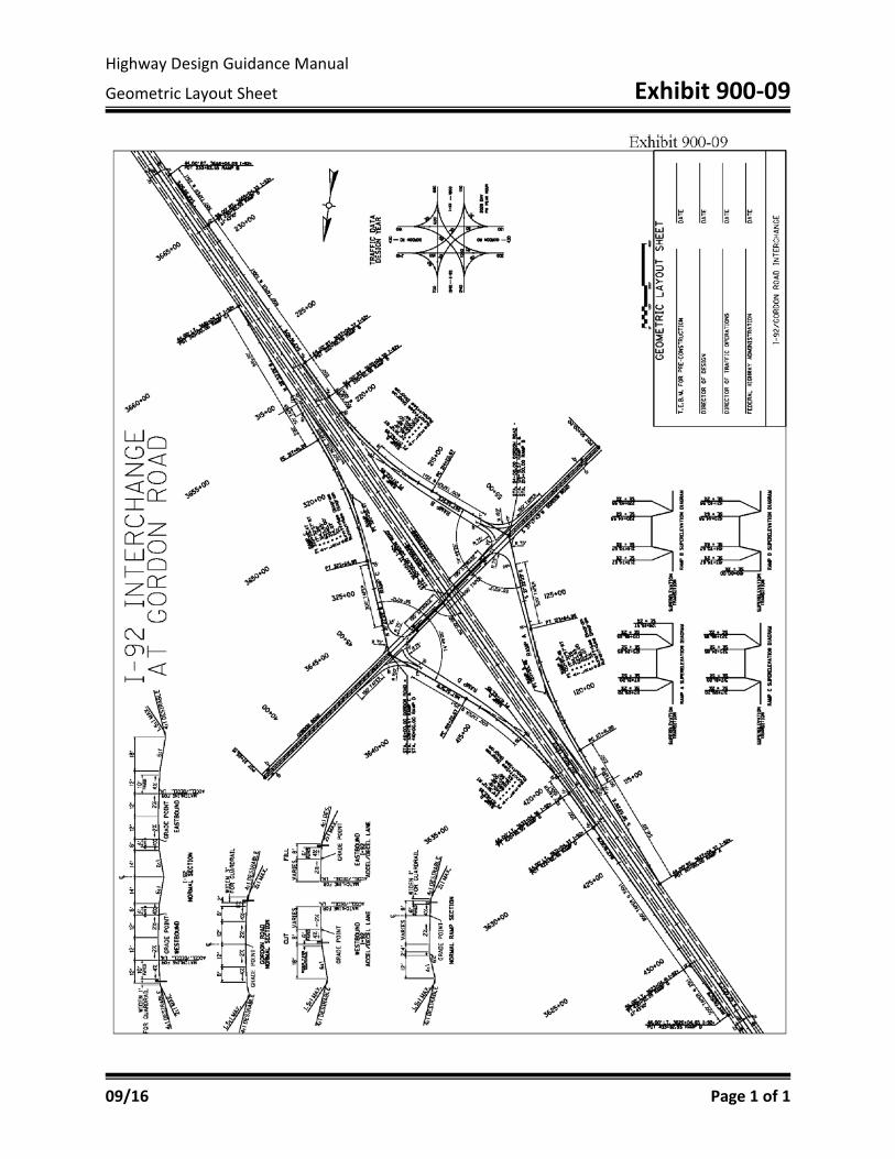
HD-904.8 GEOMETRIC LAYOUT SHEET (GLS)
For interchanges, the project manager is to recommend the chosen alternative to the Director of the Division of Highway Design by submitting a Geometric Layout Sheet (GLS). The GLS should include a block for a recommendation signature of the project manager and approval signatures of the directors of the Division of Highway Design and the Division of Traffic Operations. This layout sheet should show all ramps, lane widths, tapers, curve data, typical sections, access control information, and superelevation transitions of all roadways. For grade-separation and interchange projects on interstates, the Federal Highway Administration (FHWA) shall be involved in the decision process, and the geometric layout sheet shall be submitted to that agency for approval. For additional information on

INTERSECTIONS
Interchanges HD-904
09/16 Page 4 of 4
interchange submittals to FHWA, including the Interchange Modification Report (IMR) and the interchange Justification Study (IJS). See HD-203 and Exhibit 900-09.

Highway Design Guidance Manual
Pavement Development Sheet Exhibit 900-01
09/16 Page 1 of 3

Highway Design Guidance Manual
Pavement Development Sheet Exhibit 900-01
09/16 Page 2 of 3

Highway Design Guidance Manual
Pavement Development Sheet Exhibit 900-01
09/16 Page 3 of 3
Highway Design Guidance Manual
Basic Geometric Elements of a Roundabout Exhibit 900-02
09/16 Page 1 of 1

Highway Design Guidance Manual
Example: Cross Road Profile Adjustment Exhibit 900-03
09/16 Page 1 of 1

Highway Design Guidance Manual
Common Practice for Ramp Tapers Exhibit 900-04
09/16 Page 1 of 1

Highway Design Guidance Manual
Typical Sections: One Lane Ramps Exhibit 900-05
09/16 Page 1 of 1

Highway Design Guidance Manual
Typical Sections: Two Lane Ramps Exhibit 900-06
09/16 Page 1 of 1

Highway Design Guidance Manual
Common Practices for Ramp Terminals at Crossroads (Rural) Exhibit 900-07
09/16 Page 1 of 1

Highway Design Guidance Manual
Common Practices for Ramp Terminals at Crossroads (Urban) Exhibit 900-08
09/16 Page 1 of 1
Highway Design Guidance Manual
Geometric Layout Sheet Exhibit 900-09
09/16 Page 1 of 1